


Languages
Pages
Legal

Dynacord | DCS 412R
DCS 412R
www.dynacord.com
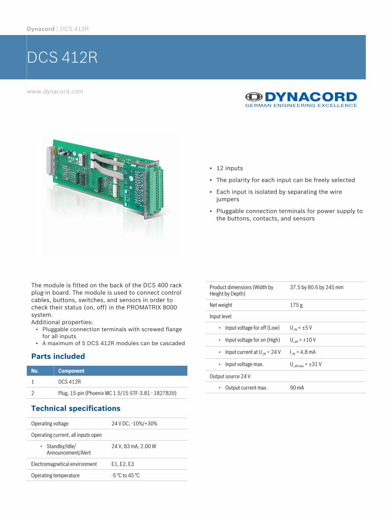
▪ 12 inputs
▪ The polarity for each input can be freely selected
▪ Each input is isolated by separating the wirejumpers
▪ Pluggable connection terminals for power supply tothe buttons, contacts, and sensors
The module is fitted on the back of the DCS 400 rackplug-in board. The module is used to connect controlcables, buttons, switches, and sensors in order tocheck their status (on, off) in the PROMATRIX 8000system.Additional properties:
• Pluggable connection terminals with screwed flangefor all inputs
• A maximum of 5 DCS 412R modules can be cascaded
Parts included
No. Component
1 DCS 412R
2 Plug, 15-pin (Phoenix MC 1.5/15-STF-3.81 - 1827839)
Technical specifications
Operating voltage 24 V DC, -10%/+30%
Operating current, all inputs open
• Standby/Idle/Announcement/Alert
24 V, 83 mA, 2.00 W
Electromagnetical environment E1, E2, E3
Operating temperature -5 °C to 45 °C
Product dimensions (Width byHeight by Depth)
37.5 by 80.6 by 245 mm
Net weight 175 g
Input level
• Input voltage for off (Low) U_IN < ±5 V
• Input voltage for on (High) U_IN > ±10 V
• Input current at U_IN = 24 V I_IN = 4.8 mA
• Input voltage max. U_IN max = ±31 V
Output source 24 V
• Output current max. 90 mA
P/S
ID
P/S
+24V
A1
B16Input 1
A2
B17Input 2
A3
B18Input 3
A4
B19Input 4
A5
B20Input 5
A6
B21Input 6
A7
B22Input 7
A8
B23Input 8
A9
B24Input 9
A10
B25Input 10
A11
B26Input 11
A12
B27Input 12
+24V
EN1
DATA1
CLK1
EN1_A
DATA_A
CLK1_A
DC
DCt+5V+24V
BR14
BR13
CN
to B
ackp
lane
GND
BR1
BR2
BR3
BR4
BR5
BR6
BR7
BR8
BR9
BR10
BR11
BR12
A13
B28GND
REF-OUT+24V
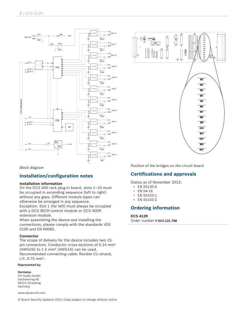
Block diagram
Installation/configuration notes
Installation informationOn the DCS 400 rack plug-in board, slots 1–10 mustbe occupied in ascending sequence (left to right)without any gaps. Different module types canotherwise be arranged in any sequence.Exception: Slot 1 (far left) must always be occupiedwith a DCS 801R control module or DCS 405Rextension module.When assembling the device and installing theconnections, please comply with the standards VDE0100 and EN 60065.
ConnectorThe scope of delivery for the device includes two 15-pin connectors. Conductor cross-sections of 0.14 mm²(AWG26) to 1.5 mm² (AWG16) can be used.Recommended connecting cable: flexible CU strand,LiY, 0.75 mm².
Position of the bridges on the circuit board
Certifications and approvals
Status as of November 2012:• EN 50130-4• EN 54-16• EN 55103-1• EN 55103-2
Ordering information
DCS 412ROrder number F.01U.121.788
2 | DCS 412R
Represented by:
Germany: EVI Audio GmbHSachsenring 6094315 StraubingGermany
www.dynacord.com
© Bosch Security Systems 2013 | Data subject to change without noticeDocument Number | Vs1 | 19. Mar 2013
Top Related