


Languages
Pages
Legal


Series 40Axial PistonMotors
TechnicalInformation
520L0636 • Rev FE • April 20112
© 2011 Sauer-Danfoss. All rights reserved.
Sauer-Danfoss accepts no responsibility for possible errors in catalogs, brochures and other printed material. Sauer -Danfoss reserves the right to alter its products without prior notice. This also applies to products already ordered, provided that such alterations can be made without affecting agreed specifications. All trademarks in this material are properties of their respective owners. Sauer-Danfoss, the Sauer-Danfoss logotype, the Sauer-Danfoss S-icon, PLUS+1™, What really matters is inside® and Know-How in Motion™ are trademarks of the Sauer-Danfoss Group.
Series 40 Axial Piston MotorsTechnical Information
Revisions
Revisions
Table of RevisionsDate Page Changed Rev.
April 2011 34, 36 correct system pressure gauge port 7/16-20 FE
August 2010 last new back page FD
March 2010 various minor edits FC
November 2007 31 correction to maximum torque rating 15 and 19 tooth FB
April 2007 29 Revised dimensions for straight keyed shaft FA
September-2006 21-22 Corrections in model code examples F
September-2005 Major Revision E

3520L0636 • Rev FE • April 2011
Series 40 Axial Piston MotorsTechnical InformationContents
GeneRaL DesCRiPtion
teChniCaL sPeCifiCations
oPeRatinG PaRameteRs
system DesiGn PaRameteRs
PRoDuCt CoDinG
featuRes anD oPtions
Basic design ...................................................................................................................................................... 5Key features ...................................................................................................................................................... 6Cross sections .................................................................................................................................................. 7System circuit diagram ................................................................................................................................. 8M46 motor schematic .................................................................................................................................. 8
Overview ........................................................................................................................................................... 9General ............................................................................................................................................................... 9Features and options .................................................................................................................................... 9Specifications ................................................................................................................................................... 9Operating parameters ................................................................................................................................10Fluid specifications ......................................................................................................................................10Hydraulic unit life .........................................................................................................................................10Performance ...................................................................................................................................................11Bearing life and external shaft loading ...............................................................................................12
Fluids .................................................................................................................................................................14Viscosity ...........................................................................................................................................................14Temperature ...................................................................................................................................................14Case pressure .................................................................................................................................................14Pressure ratings .............................................................................................................................................15Speed ratings .................................................................................................................................................16
Sizing equations ...........................................................................................................................................17Flow ........................................................................................................................................................17Speed .....................................................................................................................................................17Torque....................................................................................................................................................17Power .....................................................................................................................................................17Variables ...............................................................................................................................................17
Filtration...........................................................................................................................................................18Bypass valve ...................................................................................................................................................18Loop flushing valve......................................................................................................................................19Redundant braking system requirement ............................................................................................20Reservoir ..........................................................................................................................................................20Overpressure protection ...........................................................................................................................20
Revised model code ....................................................................................................................................21Name plate .....................................................................................................................................................21Model code modules ..................................................................................................................................21
Fixed motor .........................................................................................................................................21Variable motor ....................................................................................................................................22
Displacement limiters .................................................................................................................................23Displacement limiter M35 MV .................................................................................................................23Displacement limiter M46 MV .................................................................................................................23Speed sensor option ...................................................................................................................................24Pulse pickup and connector .....................................................................................................................25

520L0636 • Rev FE • April 20114
Series 40 Axial Piston MotorsTechnical InformationContents
instaLLation DRawinGs
sChematiCs
ContRoL oPtions
shaft oPtions
Cross-section of speed sensor on cylinder kit ...................................................................................25Shaft options ..................................................................................................................................................26Through-shaft options ...............................................................................................................................26
M25 MF ............................................................................................................................................................27M35/44 MF ......................................................................................................................................................28M35/44 MV .....................................................................................................................................................30M46 MV ............................................................................................................................................................31
Direct displacement control (DDC) ........................................................................................................32Two-position hydraulic control ...............................................................................................................33
M25 MF: axial ports, twin ports, loop flushing, speed sensor ........................................................34M25 MF: mounting flange, ........................................................................................................................35M35/M44 MF: mounting flange...............................................................................................................35M35/M44 MF: axial ports, twin ports, loop flushing, speed sensor .............................................36M35/M44 MF: side ports, through shaft ...............................................................................................37M35/M44 MV: twin ports ...........................................................................................................................38M35/M44 MV: mounting flange, trunnion control............................................................................39M46 MV: side ports, loop flushing ...........................................................................................................40M46 MV: axial ports, loop flushing ..........................................................................................................41M46 MV: side ports, thru shaft twin ports, loop flushing ................................................................42M46 MV: mounting flange .........................................................................................................................43M46 MV: control ports ................................................................................................................................44
M25/M35/M44 fixed motor schematics (no loop flushing) ..........................................................45M25/M35/M44 fixed motor schematics ...............................................................................................45M35/M44 variable motor schematics ...................................................................................................45M46 variable motor schematics ..............................................................................................................45
featuRes anD oPtions

5520L0636 • Rev FE • April 2011
Series 40 Axial Piston MotorsTechnical InformationGeneral description
BasiC DesiGn Series 40 is a family of hydrostatic pumps and motors for medium power applications with maximum loads of 345 bar [5000 psi]. These pumps and motors can be applied together or combined with other products in a system to transfer and control hydraulic power.
Series 40 transmissions (pump plus motor) provide an infinitely variable speed range between zero and maximum in both forward and reverse modes of operation. The pumps and motors each come in four frame sizes: M25, M35, M44, and M46.
series 40 pumps are compact, high power density units. All models use the parallel axial piston / slipper concept in conjunction with a tiltable swashplate to vary the pump’s displacement. Reversing the angle of the swashplate reverses the flow of fluid from the pump, reversing the direction of rotation of the motor output.
Series 40 M35, M44, and M46 pumps may include an integral charge pump to provide system replenish ing and cooling fluid flow, as well as servo control fluid flow on M46 pumps. M25 pumps are designed to receive charge flow from an auxiliary circuit or from a gear pump mounted on the auxiliary mounting pad. Series 40 pumps feature a range of auxiliary mounting pads to accept auxiliary hydraulic pumps for use in complementary hydraulic systems.
Series 40 M46 pumps offer proportional controls with either manual, hydraulic, or electronic actuation. An electric three-position control is also available. The M25, M35, and M44 pumps include a trunnion style direct displacement control.
series 40 motors also use the parallel axial piston / slipper design in conjunction with a fixed or tiltable swashplate. The family includes M25, M35, M44 fixed motor units and M35, M44, M46 variable motor units.
The M35 and M44 variable motors feature a trunnion style swashplate and direct displacement control. The M46 variable motors use a cradle swashplate design and a two-position hydraulic servo control.

520L0636 • Rev FE • April 20116
Series 40 Axial Piston MotorsTechnical InformationGeneral description
Key featuRes • 3 sizes of variable displacement motors
• 3 sizes of fixed displacement motors
• Efficient axial piston design
• Complete family of control systems
• Proven reliability and performance
• Compact, lightweight
• Worldwide sales and service
7520L0636 • Rev FE • April 2011
Series 40 Axial Piston MotorsTechnical InformationGeneral description
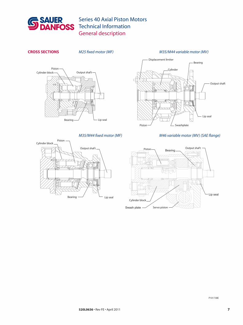
CRoss seCtions
SwashplatePiston
Bearing
Cylinder
Displacement limiter
Cylinder block
PistonOutput shaft
Lip sealBearing
Cylinder blockPiston
Output shaft
Lip sealBearingCylinder block
Piston Output shaft
Lip seal
Bearing
Servo piston
P101738E
Output shaft
Lip seal
Swash plate
M25 fixed motor (MF) M35/M44 variable motor (MV)
M35/M44 fixed motor (MF) M46 variable motor (MV) (SAE flange)
520L0636 • Rev FE • April 20118
Series 40 Axial Piston MotorsTechnical InformationGeneral description
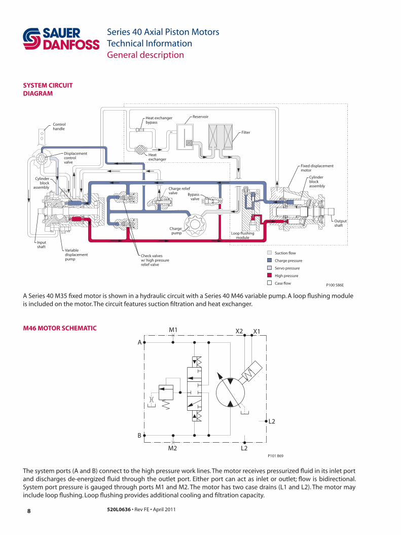
system CiRCuit DiaGRam
Inputshaft
Suction flow
Servo pressure
High pressure
Case flow
Charge pressure
Outputshaft
Cylinderblockassembly
Filter
Chargepump
Reservoir
Fixed displacementmotor
Cylinderblock
assembly
Heatexchanger
Check valvesw/ high pressurerelief valve
Variabledisplacementpump
Heat exchangerbypass
Charge reliefvalve
Displacementcontrolvalve
Controlhandle
Bypassvalve
Loop flushingmodule
P100 586E
A Series 40 M35 fixed motor is shown in a hydraulic circuit with a Series 40 M46 variable pump. A loop flushing module is included on the motor. The circuit features suction filtration and heat exchanger.
m46 motoR sChematiC
M2
B
A
M1 X2 X1
L2
L2
P101 869
The system ports (A and B) connect to the high pressure work lines. The motor receives pressurized fluid in its inlet port and discharges de-energized fluid through the outlet port. Either port can act as inlet or outlet; flow is bidirectional. System port pressure is gauged through ports M1 and M2. The motor has two case drains (L1 and L2). The motor may include loop flushing. Loop flushing provides additional cooling and filtration capacity.

9520L0636 • Rev FE • April 2011
Series 40 Axial Piston MotorsTechnical InformationTechnical Specifications
featuRes anD oPtions
sPeCifiCations
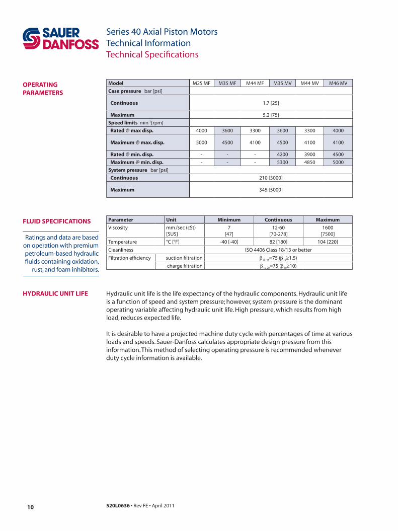
Specifications and operating parameters are shown below. Not all hardware options are available for all configurations. For additional information, see Operating parameters, page 14, System design parameters, page 17, Product coding, page 21, Features and options, page 23 and Control options, page 32.
oveRview
GeneRaL
model unit m25mf m35 mf m44 mf m35mv m44mv m46 mv
model configuration Fixed Fixed Fixed Variable Variable Variable
type of mounting SAE B SAE B SAE B SAE B SAE B SAE B
Displacement cm3/rev
[in3/rev]25 [1.50] 35 [2.14] 44 [2.65] 35 [2.14] 44 [2.65] 46 [2.80]
weight kg [lbf ] 11 [26] 11 [26] 11 [26] 21 [47] 21 [47] 23 [51]
mass moment of inertia kg•m2
[slug•ft2]
0.0018
[0.0013]
0.0033
[0.0024]
0.0032
[0.0023]
0.0033
[0.0024]
0.0032
[0.0023]
0.0050
[0.0037]
model M25 MF M35 MF M44 MF M35 MV M44 MV M46 MV
type of mounting SAE B SAE B SAE B SAE B SAE B SAE B or
Port connections Twin, AxialSide, Twin,
Axial
Side, Twin,
AxialTwin Twin
Side, Twin,
Axial
output shaft optionsSplined
Tapered
Splined
Tapered
Straight Key
Splined
Tapered
Straight Key
Splined SplinedSplined
Tapered
Control options - - - DDC DDC Hyd. 2-pos.
Loop flushing Option Option Option Option Option Option
Displacement limiters - - - Option Option Option
speed sensors Option Option Option - - Option
520L0636 • Rev FE • April 201110
Series 40 Axial Piston MotorsTechnical InformationTechnical Specifications
oPeRatinG PaRameteRs
Ratings and data are based on operation with premium petroleum-based hydraulic fluids containing oxidation,
rust, and foam inhibitors.
fLuiD sPeCifiCations Parameter unit minimum Continuous maximum
Viscosity mm /sec (cSt) [SUS]
7[47]
12-60[70-278]
1600[7500]
Temperature °C [°F] -40 [-40] 82 [180] 104 [220]
Cleanliness ISO 4406 Class 18/13 or better
Filtration efficiency suction filtration β35-44=75 (β10≥1.5)
charge filtration β15-20=75 (β10≥10)
model M25 MF M35 MF M44 MF M35 MV M44 MV M46 MV
Case pressure bar [psi]
Continuous 1.7 [25]
maximum 5.2 [75]
speed limits min-1[rpm]
Rated @ max disp. 4000 3600 3300 3600 3300 4000
maximum @ max. disp. 5000 4500 4100 4500 4100 4100
Rated @ min. disp. - - - 4200 3900 4500
maximum @ min. disp. - - - 5300 4850 5000
system pressure bar [psi]
Continuous 210 [3000]
maximum 345 [5000]
Hydraulic unit life is the life expectancy of the hydraulic components. Hydraulic unit life is a function of speed and system pressure; however, system pressure is the dominant operating variable affecting hydraulic unit life. High pressure, which results from high load, reduces expected life.
It is desirable to have a projected machine duty cycle with per centages of time at various loads and speeds. Sauer-Danfoss calculates appropriate design pressure from this information. This method of selecting operating pressure is recom mended whenever duty cycle information is available.
hyDRauLiC unit Life
11520L0636 • Rev FE • April 2011
Series 40 Axial Piston MotorsTechnical InformationTechnical Specifications
PeRfoRmanCe
Motor performance as a function of operating speed
Motor performance as a function of operating speed
All pressure limits are differential pressures and assume normal charge pressure. Series 40 motors will meet satisfactory life expectancy if applied within the parameters specified in this bulletin. For more detailed information on hydraulic unit life see BLn‑9884 Pressure and Speed Limits.
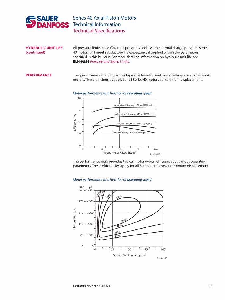
This performance graph provides typical volumetric and over all efficiencies for Series 40 motors. These efficiencies apply for all Series 40 motors at maximum displacement.
100
80
95
90
85
Effic
ien
cy -
%
0 25 50 75 100
Speed - % of Rated Speed
Volumetric Efficiency - 170 bar [2500 psi]
Volumetric Efficiency - 345 bar [5000 psi]
Overall Efficiency - 170 bar [2500 psi]
Overall Efficiency - 345 bar [5000 psi]
P100 455E
The performance map provides typical motor overall efficiencies at various operating param eters. These efficiencies apply for all Series 40 motors at maximum displacement.
5000
0
4000
3000
2000
1000
Syst
em P
ress
ure
0 25 50 75 100
Speed - % of Rated Speed
psi345
0
270
210
140
bar
70 80%85%
88%
89%
80%
85%
88%
89%
P100 456E
hyDRauLiC unit Life(continued)

520L0636 • Rev FE • April 201112
Series 40 Axial Piston MotorsTechnical InformationTechnical Specifications
BeaRinG Life anD exteRnaL shaft LoaDinG
Bearing life is a function of speed, pressure and swashplate angle, plus any external loads. Other life factors include oil type and viscosity.
In vehicle propulsion drives with no external loads, where the speed, pressure, and swashplate angle are often changing, normal bearing ß10 (90% survival) life will exceed the hydraulic unit life. In non-propel drives, such as conveyors or fan drives, the operating speed and pressure may be nearly constant leading to a distinctive duty cycle compared to that of a propulsion drive. In propel applications, Sauer-Danfoss recommends a bearing life review.
Series 40 motors are designed with bearings that can accept some incidental external radial and thrust loads. However, any amount of external load will reduce the expected bearing life.
The allowable radial shaft loads are a function of the load position, the load orientation, and the operating pressures of the hydraulic unit. All external shaft loads have an effect on bearing life. In motor applications where external shaft loads cannot be avoided, the impact on bearing life can be mini mized by orienting the load to the 180 degree position (see Direction of external shaft load, next page).
The recommended maximum radial load (Re) is based on an external moment (M
e) and
the distance (L) from the mounting flange to the load, (see table at below). The loads in the table reflect a worst case external load orientation (0 degrees), a continuously applied working pressure of 140 bar (2000 psi), 20 bar (285 psi) charge pressure, 1800 min-1(rpm), and a bearing life (ß10) of 2000 hours. Avoid thrust loads in either direction.
The recommended maximum allowable radial load is calculated as: Re = Me / L
If continuously applied external radial loads exceed the recommended maximum allowable, or thrust loads are known to occur, contact Sauer-Danfoss for an evaluation of unit bearing life. Optional high capacity bearings are available.
Tapered output shafts or clamp-type couplings are recommended for applications where radial shaft side loads are present.
Re Maximum radial side load
me Maximum external moment
L Distance from mounting flange to point of load
fB Force of block (applies at center of gravity)
t Thrust load
m25 m35/44 m46
Me N•m [lbf•in] 29 [255] 25 [225] 24 [215]
Shaft loading parameters
Recommended maximum external shaft moments

13520L0636 • Rev FE • April 2011
Series 40 Axial Piston MotorsTechnical InformationTechnical Specifications
External shaft loads
Direction of external shaft load
BeaRinG Life anD exteRnaL shaft LoaDinG(continued)
L
Re
FB
T
P100 453E
0 Re
180 Re
90 Re 270 Re
Axis of swashplaterotation
End viewof shaft
P100 454E
520L0636 • Rev FE • April 201114
Series 40 Axial Piston MotorsTechnical InformationOperating parameters
fLuiDs
visCosity
temPeRatuRe
Case PRessuRe
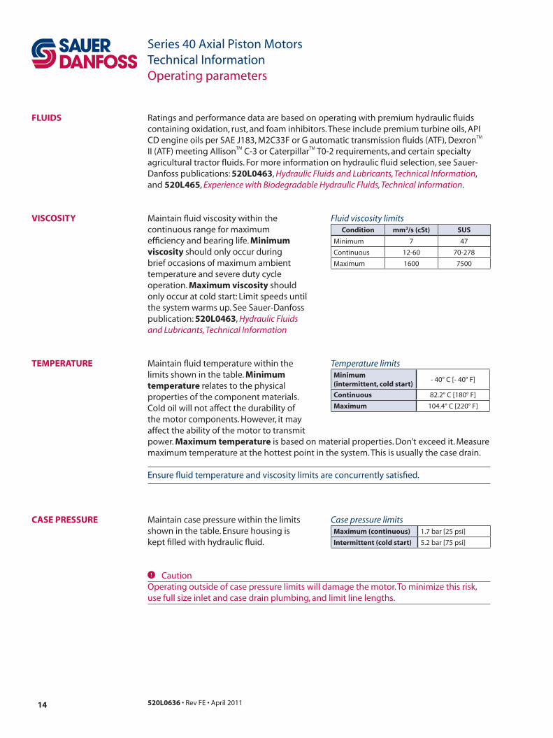
Ratings and performance data are based on operating with premium hydraulic fluids containing oxidation, rust, and foam inhibitors. These include premium turbine oils, API CD engine oils per SAE J183, M2C33F or G automatic transmission fluids (ATF), DexronTM II (ATF) meeting AllisonTM C-3 or CaterpillarTM T0-2 requirements, and certain specialty agricultural tractor fluids. For more information on hydraulic fluid selection, see Sauer-Danfoss publications: 520L0463, Hydraulic Fluids and Lubricants, Technical Information, and 520L465, Experience with Biodegradable Hydraulic Fluids, Technical Information.
Maintain fluid viscosity within the continuous range for maximum efficiency and bearing life. minimum viscosity should only occur during brief occasions of maximum ambient temperature and severe duty cycle operation. maximum viscosity should only occur at cold start: Limit speeds until the system warms up. See Sauer-Danfoss publication: 520L0463, Hydraulic Fluids and Lubricants, Technical Information
Maintain fluid temperature within the limits shown in the table. minimum temperature relates to the physical properties of the component materials. Cold oil will not affect the durability of the motor components. However, it may affect the ability of the motor to transmit
Fluid viscosity limitsCondition mm2/s (cst) sus
Minimum 7 47
Continuous 12-60 70-278
Maximum 1600 7500
Temperature limitsminimum (intermittent, cold start)
- 40° C [- 40° F]
Continuous 82.2° C [180° F]
maximum 104.4° C [220° F]
power. maximum temperature is based on material properties. Don’t exceed it. Measure maximum temperature at the hottest point in the system. This is usually the case drain.
Ensure fluid temperature and viscosity limits are concurrently satisfied.
Maintain case pressure within the limits shown in the table. Ensure housing is kept filled with hydraulic fluid.
Case pressure limitsmaximum (continuous) 1.7 bar [25 psi]
intermittent (cold start) 5.2 bar [75 psi]
C CautionOperating outside of case pressure limits will damage the motor. To minimize this risk, use full size inlet and case drain plumbing, and limit line lengths.

15520L0636 • Rev FE • April 2011
Series 40 Axial Piston MotorsTechnical InformationOperating parameters
PRessuRe RatinGs The table, Operating parameters, page 10, gives maximum and continuous pressure ratings for each displacement. Not all displacements operate under the same pressure limits. Definitions of the operating pressure limits appear below.
system pressure is the differential pressure between system ports A and B. It is the dominant operating variable affecting hydraulic unit life. High system pressure, which results from high load, reduces expected life. System pressure must remain at or below continuous working pressure during normal operation to achieve expected life.
Continuous working pressure is the average, regularly occurring operating pressure. Operating at or below this pressure should yield satisfactory product life.
maximum (peak) working pressure is the highest intermittent pressure allowed. Maximum machine load should never exceed this pressure. For all applications, the load should move below this pressure.
All pressure limits are differential pressures referenced to low loop (charge) pressure. Subtract low loop pressure from gauge readings to compute the differential.
System pressure limitsPressure Limits bar psi
Continuous 210 3000
Maximum 345 5000

520L0636 • Rev FE • April 201116
Series 40 Axial Piston MotorsTechnical InformationOperating parameters
sPeeD RatinGs The table, Operating parameters, page 10, gives rated and maximum speeds for each displacement. Not all displacements operate under the same speed limits. Definitions of these speed limits appear below.
Rated speed is the maximum recommended operating speed at full power condition. Operating at or below this speed should yield satisfactory product life. In vehicle propel applications, maximum motor speed during unloaded, on-road travel over level ground should not exceed this limit.
maximum speed is the highest operating speed permitted. Exceeding maximum speed reduces motor life and can cause loss of hydrostatic power and braking capacity. Never exceed the maximum speed limit under any operating conditions.
W Warningunintended vehicle or machine movement hazard. The loss of hydrostatic drive line power, in any mode of operation (forward, neutral, or reverse) may cause the system to lose hydrostatic braking capacity. You must provide a braking system, redundant to the hydrostatic transmission, sufficient to stop and hold the vehicle or machine in the event of hydrostatic drive power loss.
Speed limits
Limit min-1(rpm) m25 mf m35 mf m44 mf m35 mv m44 mv m46 mv
Rated at max. displ... 4000 3600 3300 3600 3300 4000
Maximum at max. displ...5000 4500 4100 4500 4100 4100
Rated at min. displ...- - - 4200 3900 4500
Maximum at min. displ...- - - 5300 4850 5000

17520L0636 • Rev FE • April 2011
Series 40 Axial Piston MotorsTechnical InformationSystem design parameters
sizinG equations
Based on si units Based on us units
SI units [US units]
Vg = Displacement per revolution cm3/rev [in3/rev]pO = Outlet pressure bar [psi]pi = Inlet pressure bar [psi]∆p = pO - pi (system pressure) bar [psi]n = Speed min-1 (rpm)ηv = Volumetric efficiencyηm = Mechanical efficiencyηt = Overall efficiency (ηv • ηm)
Variables
Flow
Torque
Power
Input flow Q = (l/min)
Motor speed n = (min-1 )
Output torque M = (N•m)
Output power P = (kW)
Vg • ∆p • ηm
20 • π
Q • ∆p • ηt 600
Vg • n1000 • ηv
Q • 1000 • ηv
Vg
Speed
Input flow Q = (US gal/min)
Motor speed n = (min-1)
Output torque M = (lbf•in)
Output power P = (hp)
Vg • ∆p • ηm
2 • π
Q • ∆p • ηt
1714
Vg • n231 • ηv
Q • 231 • ηv
Vg
Use the following equations to compute output power, torque, speed, and input flow. Selecting the right motor starts with an evaluation of system requirements such as speed and torque. Select a motor that will transmit the required torque, then select a pump that will meet the flow and pressure requirements of the motor. For more information on hydrostatic drive selection, refer to Sauer-Danfoss applications guideline BLn‑9885, Selection of Drive Line Components.
520L0636 • Rev FE • April 201118
Series 40 Axial Piston MotorsTechnical InformationSystem design parameters
fiLtRation To prevent damage to the system, including premature wear, fluid entering the motor must be free of contaminants. Series 40 motors require system filtration capable of maintaining fluid cleanliness at ISO 4406-1999 class 22/18/13 or better.
Consider these factors when selecting a system filter:• Cleanliness specifications• Contaminant ingression rates• Flow capacity• Desired maintenance interval
The filter may be located either on the inlet (suction filtration) or discharge (charge pressure fil tration) side of the charge pump. Series 40 pumps are available with provisions for either suction or charge pressure filtration to filter the fluid entering the charge circuit (see next page).
Typically, a filter with a beta ratio of β10 = 1.5 to 2.0 is adequate. However, open circuit systems supplied from a common reservoir may have considerably higher requirements. Because each system is unique, only a thorough testing and evaluation program can fully validate the filtration system. For more information, see Sauer-Danfoss publication 520L0467, Design Guidelines for Hydraulic Fluid Cleanliness.
ByPass vaLve In some applications it is desirable to bypass fluid around the variable displacement pump, for example; to allow a vehicle to move short distances at low speeds without running the prime mover. This is done by opening a manually operated bypass valve. This valve connects both sides of the pump/motor circuit and allows the motor to turn. During normal operation, this valve must be fully closed .
Bypass valves are available in Series 40 pumps. See Sauer-Danfoss publication: 520L0635, Series 40 Pumps Technical Information.
Bypass valves are intended for moving a machine or vehicle for very short distances at very slow speeds. They are NOT intended as tow valves.

19520L0636 • Rev FE • April 2011
Series 40 Axial Piston MotorsTechnical InformationSystem design parameters
LooP fLushinG vaLve Series 40 motors may incorporate an integral loop flushing valve. Installations that require additional fluid to be removed from the main hydraulic circuit because of fluid cooling or cleanliness requirements, will benefit from loop flushing. A loop flushing valve will remove heat and contaminants from the main loop at a rate faster than otherwise possible. Contact your Sauer-Danfoss representative for production availability on specific frame size motors.
Series 40 loop flushing valves include a loop flushing relief valve with integral orifice. The flushing flow is a function of the pump charge relief valve, and the orifice size.
Loop flushing flows of 3 to 7 l/min [0.75 to 2 US gal/min] are adequate for most applications. Contact your Sauer-Danfoss representative for assistance.
W waRninGIncorrect charge pressure settings may result in the inability to build required system pressure and/or inadequate loop flushing flows. Maintain correct charge pressure under all conditions.
Loop flushing relief valvewith orifice
Loop flushingshuttle v alve
P100 448E
Loop flushing valve
15.14[4.00]
11.36[3.00]
3.79[1.00]
08.62[125]
12.07[175]
15.51[225]
Charge pressure bar [psi]
19.96[275]
22.41[325]
25.86[375]
7.57[2.00]
Flo
w l/
min
[US
gal
/min
]
P100 643E
Typical loop flushing flow as a function of charge pressure

520L0636 • Rev FE • April 201120
Series 40 Axial Piston MotorsTechnical InformationSystem design parameters
W Warningunintended vehicle or machine movement hazard. The loss of hydrostatic drive line power, in any mode of operation (forward, neutral, or reverse) may cause the system to lose hydrostatic braking capacity. You must provide a braking system, redundant to the hydrostatic transmission, sufficient to stop and hold the vehicle or machine in the event of hydrostatic drive power loss.
ReDunDant BRaKinG system RequiRement
ReseRvoiR The reservoir provides clean fluid, dissipates heat, and removes entrained air from the hydraulic fluid. It allows for fluid volume changes associated with fluid expansion and cylinder differential volumes. Minimum reservoir capacity depends on the volume needed to perform these functions. Typically, a capacity of one half the charge pump flow (per minute) is satisfactory for a closed reservoir. Open circuit systems sharing a common reservoir will require greater fluid capacity.
Locate the reservoir outlet (suction line) near the bottom, allowing clearance for settling foreign particles. Use a 100 - 125 µm screen covering the outlet port. Place the reservoir inlet (return lines) below the lowest expected fluid level, as far away from the outlet as possible. Use a baffle (or baffles) between the reser voir inlet and outlet ports to reduce aeration and fluid surging.
oveRPRessuRe PRoteCtion
Series 40 motors (as well as other system components) have pressure limits. Relief valves or pressure limiters should be present in the high pressure circuit to protect components from excessive pressures.
C CautionHigh pressure relief valves are intended for transient overpressure protection and are not intended for continuous pressure control. Operation over relief valves for extended peri-ods of time may result in severe heat build up. High flows over relief valves may result in pressure levels exceed ing the nominal valve setting and potential damage to system compo nents.

21520L0636 • Rev FE • April 2011
Series 40 Axial Piston MotorsTechnical InformationProduct coding
ReviseD moDeL CoDe The model code is a modular description of a specific product and its options. To create an order code to include the specific options desired, see the Series 40 Motor Model Code Supplement or the Series 40 Price Book.
name PLate Name plate
Place of manufacture
Modelnumber
Serialnumber
Modelcode
Made in USA
Model-No/Ident-No.
R NN A A BLL DR AFF A CNN
MMV 046 C B A B A A Model Code
Serial-No A - 96 - 26 - 12345
M46-2001
P101 372E
moDeL CoDe moDuLes
M M V S 4 6 C
Product
Displacement
Type
C D E F G T Z * * * - - - - -
P104 427E
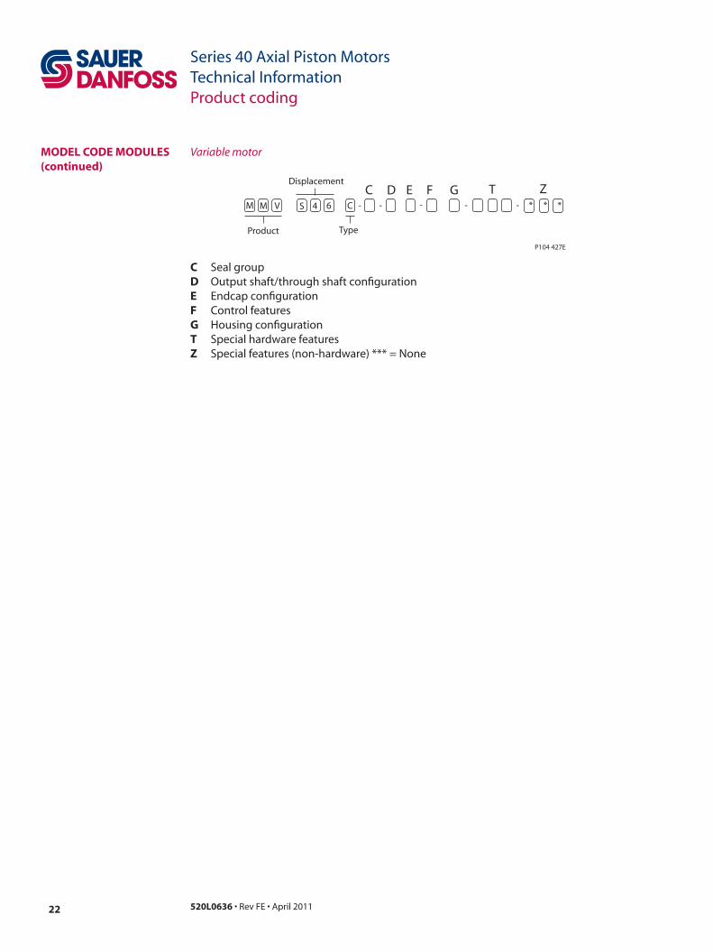
C Seal groupD Output shaft/through shaft configuratione Endcap configurationf Cylinder block groupG Housing configurationt Special hardware featuresz Special features (non-hardware) *** = None
Fixed motor
520L0636 • Rev FE • April 201122
Series 40 Axial Piston MotorsTechnical InformationProduct coding
M M V S 4 6 C
Product
Displacement
Type
C D E F G T Z * * * - - - - -
P104 427E
C Seal groupD Output shaft/through shaft configuratione Endcap configurationf Control featuresG Housing configurationt Special hardware featuresz Special features (non-hardware) *** = None
Variable motormoDeL CoDe moDuLes (continued)
23520L0636 • Rev FE • April 2011
Series 40 Axial Piston MotorsTechnical InformationFeatures and options
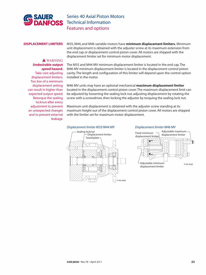
DisPLaCement LimiteRs M35, M44, and M46 variable motors have minimum displacement limiters. Minimum unit dis placement is obtained with the adjuster screw at its maximum extension from the end cap or displacement control piston cover. All motors are shipped with the displacement limiter set for minimum motor displacement.
The M35 and M44 MV minimum displacement limiter is located in the end cap. The M46 MV minimum displacement limiter is located in the displacement control piston cavity. The length and configuration of this limiter will depend upon the control option installed in the motor.
M46 MV units may have an optional mechanical maximum displacement limiter located in the displacement control piston cover. The maximum displace ment limit can be adjusted by loosening the sealing lock nut, adjusting displacement by rotating the screw with a screwdriver, then locking the adjuster by torquing the sealing lock nut.
Maximum unit dis placement is obtained with the adjuster screw standing at its maximum height out of the displacement control piston cover. All motors are shipped with the limiter set for maximum motor displacement.
WWARNINGundesirable output
speed hazard. Take care adjusting
displacement limiters. Too low of a minimum
displacement setting can result in higher than expected output speed.
Retorque the sealing locknut after every
adjustment to prevent an unexpected changes and to prevent external
leakage.
SwashplateDisplacement limiter
P100 449E
Sealing locknut
P100 450E
Fixed minimumdisplacement limiter
Adjustable minimumdisplacement limiter
Adjustable maximumdisplacement limiter
Displacement limiter M35/M44 MV Displacement limiter M46 MV

520L0636 • Rev FE • April 201124
Series 40 Axial Piston MotorsTechnical InformationFeatures and options
sPeeD sensoR oPtion Series 40 motors are available with a speed sensor option for direct measurement of motor output speed. You can use this sensor may to sense the direction and speed of motor rotation.
A special magnetic speed ring is pressed onto the outside diameter of the cylinder block. A hall effect pulse pickup is located in the motor housing. The sensor accepts supply voltage and outputs a digital pulse signal in response to the speed of the ring. The output changes its high/low state as the north and south poles of the permanently magnetized speed ring pass by the face of the sensor. The digital signal is generated at frequencies suitable for microprocessor based controls.
This sensor will operate with a supply voltage of 4.5 to 15 Vdc, and requires a current of 12 mA at 5.0 Vdc (minimum) under no load. Maximum operating current is 20 mA at 5 Vdc (maximum). Maximum operating frequency is 15 kHz. Output voltage in High State (VOH) is sensor supply voltage minus 0.5 Vdc, minimum. Output voltage in Low State (VOL) is 0.5 Vdc, maximum. The sensor is available with a Packard Weather-PackTM or 4-pin sealed connector.
Contact your Sauer-Danfoss representative for production availability on specific motor frame sizes, or for special speed sensor options.
supply voltage 4.5 - 15 Vdc
Required current12 mA @ 5 Vdc
(no load)
maximum current 20 mA @ 5Vdc
maximum frequency 15 kHz
voh Supply Vdc - 0.5 Vdc
voL 0.5 Vdc maximum
magnetic ring
Pulses/revolution
M25 M35 M44 M46
43 46 46 51
ConnectorPackard Weather-PackTM
3- pin, 4-pin
Speed sensor
Magnetic ring
Cylinder block
P100 452E
Speed sensor specifications Speed sensor cross section
25520L0636 • Rev FE • April 2011
Series 40 Axial Piston MotorsTechnical InformationFeatures and options
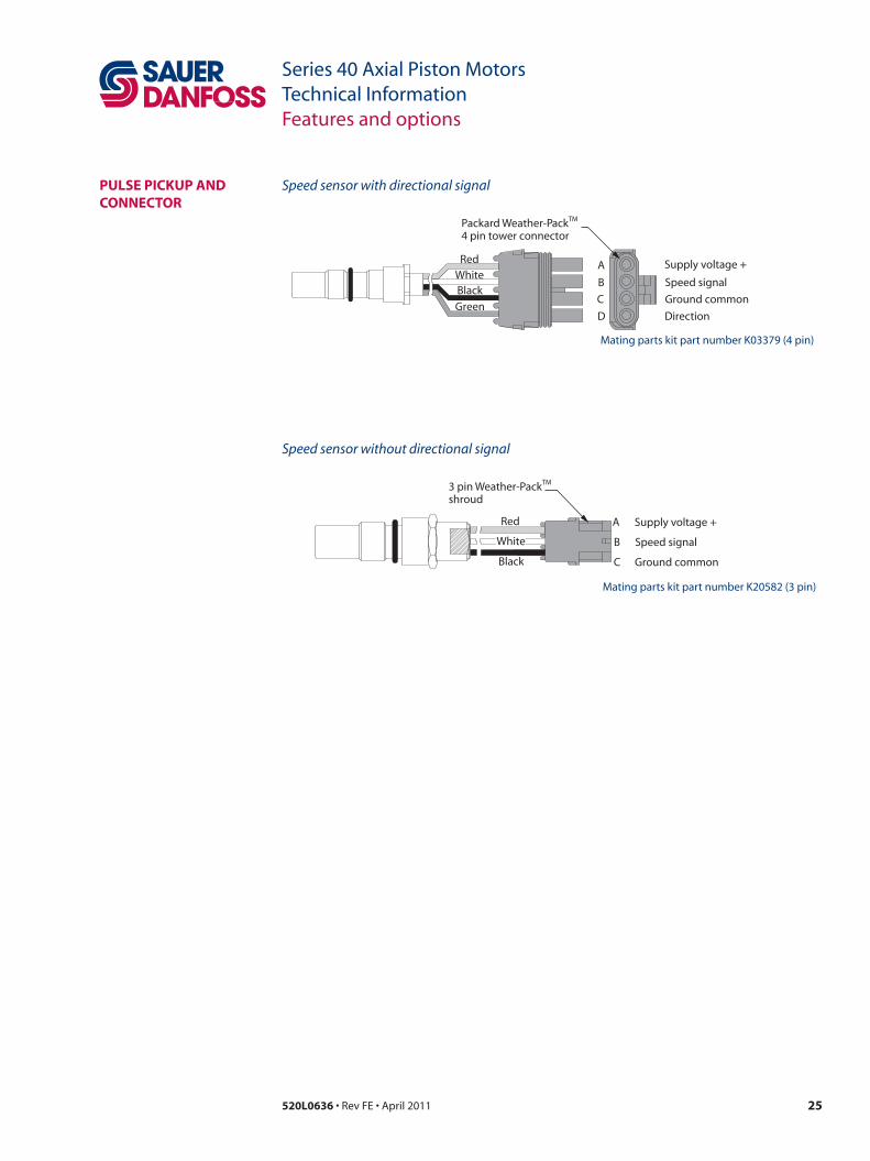
PuLse PiCKuP anD ConneCtoR
Red
Red
WhiteBlack
Black
Green
Supply voltage +
Supply voltage +
Speed signal
Speed signal
Direction
Ground common
Ground common
A
A
B
B
C
C
D
Packard Weather-Pack4 pin tower connector
3 pin Weather-Packshroud
White
P100 451E
TM
TM
Mating parts kit part number K03379 (4 pin)
Mating parts kit part number K20582 (3 pin)
Speed sensor with directional signal
Speed sensor without directional signal

520L0636 • Rev FE • April 201126
Series 40 Axial Piston MotorsTechnical InformationFeatures and options
shaft oPtions Series 40 motors are available with a variety of splined, straight keyed, and tapered shaft ends. Nominal shaft sizes and torque ratings for some available shafts are shown in the accompany ing table. Other shaft options may exist. Contact your Sauer-Danfoss representative for availability.
Torque ratings assume no external radial loading. Continuous torque ratings for splined shafts are based on spline tooth wear, and assume the mating spline has a minimum hardness of Rc 55 to full spline depth and coupling has good lubrication.
maximum torque ratings are based on shaft torsional strength and assume a maximum of 200,000 load reversals.
N•m [lbf•in] m25 mf m35 mf m44 mf m35 mv m44 mv m46 mv
Spline
13-tooth,
16/32 pitch
Continuous 80 [750] 73 [650] 73 [650] 73 [650] 73 [650] 73 [650]
Max 140 [1240] 226 [2000] 226 [2000] 226 [2000] 226 [2000] 226 [2000]
Spline
15-tooth,
16/32 pitch
Continuous - 153 [1350] 153 [1350] 153 [1350] 153 [1350] 153 [1350]
Max - 362 [3200] 362 [3200] 362 [3200] 362 [3200] 362 [3200]
Spline
19-tooth
16/32 pitch
Continuous - - - - - 194 [1710]
Max - - - - - 460 [4070]
Tapered
1.00 inchMax 140 [1240] 497 [4400] 497 [4400] - - 497 [4400]
Straight
keyed
0.875 inch
Max - 226 [2000] 226 [2000] - - -
Recommended mating splines for Series 40 splined output shafts should be in accordance with ANSI B92.1 Class 5. Sauer-Danfoss external splines are modified Class 5 Fillet Root Side Fit. The external spline Major Diameter and Circular Tooth Thickness dimensions are reduced in order to assure a clearance fit with the mating spline.
thRouGh‑shaft oPtions
Optional through-shafts are available on Series 40 fixed and variable displacement motors (as noted in the accompanying table). Through-shafts are provided for use in secondary (parking) braking systems. Through-shaft ends are not intended for continuous power transmission.
WWARNINGPotential loss of braking capacity. Exceeding these torque limits could cause shaft breakage. Ensure your application never exceeds maximum torque limits under any operating conditions.
frame size shaft spline max. torque limit
N•m [lbf•in]
M35 MF 13T 16/32 P 328 [2900]
M44 MF 13T 16/32 P 328 [2900]
M46 MV(SAE) 13T 16/32 P 328 [2900]
Shaft availability and torque ratings
Through-shaft availability and torque limitations

27520L0636 • Rev FE • April 2011
Series 40 Axial Piston MotorsTechnical InformationShaft options
Contact SAUER-DANFOSS Application Engineering for specific installation drawings. Dimensions in mm [in]
m25 mf
Code Description
torque rating
Drawing
maximum torque ratingN•m [lbf•in]
Continuous torque ratingN•m [lbf•in]
e 13-tooth16/32 pitch(ANSI B92.1 1970 - Class 5)
140 [1240] 80 [750]
20.638 [0.8125] pitch dia.30° pressure angle13 teeth, 16/32 pitchfillet root side fitper ANSI B92.1 class 5also mates withflat root side fit21.717 dia.
[0.8550]
18.8 max.[0.74]
16.5 [0.65]Full spline
7.9 [0.31]
33.32 max.[1.312]
Coupling must not protrudebeyond this surface
Mountingflange
(ref.)
P104 428E
n Ø 25.4 mm [1.000 in]1:8 taper
140 [1240] —
0.750-16 UNF-2A thd.
22.22 Gauge dia.[0.875]
38.1 [1.500] taper per footper SAE J500125.4 [1.000] nominal shaft dia.
3.81 max. [0.150]
6.30 x 22.22 dia. Woodruff key[0.248x0.875]0.25 [0.01] min. R on edges
33.3 Gauge dim.[1.311]
42.8 [1.68]
27 [1.06]
Coupling must notprotrude beyond25.4 max. [1.000]
Mountingflange
(ref.)
P104 429E

520L0636 • Rev FE • April 201128
Series 40 Axial Piston MotorsTechnical InformationShaft options
Contact SAUER-DANFOSS Application Engineering for specific installation drawings. Dimensions in mm [in]
m35/44 mf
Code Description
torque rating
Drawing
maximum torque ratingN•m [lbf•in]
Continuous torque ratingN•m [lbf•in]
a, C Splined output shaft (see table)
13 tooth 226 [2000] 13 tooth 73 [650]
T dia.
V dia.
W pitch dia.30° pressure angleY teeth, Z pitch fillet root side fitper ANSI B92.1-1970 class no. 5also mates with flatroot side fit
S
7.65 [0.301]
U
Coupling must notprotrude beyondthis surface
Mountingflange
(ref.)
P104 430E
f 15 tooth 362 [3200] 15 tooth 153 [1350]
shaft
option
shaft length
s
shaft diameter
t
full spline
u
major dia.
v
Pitch dia.
w
no.
teeth
y
Pitch
z
thru
shaft
A 33.55 [1.321] 18.8 [0.74] 16.5 [0.65] 21.72 [0.8550]20.638
[0.8125]13 16/32 ---
C 33.55 [1.321] 18.8 [0.74] 16.5 [0.65] 21.72 [0.8550]20.638
[0.8125]13 16/32 13T
F 33.55 [1.321] 21.98 [0.865] 18.5 [0.73] 24.89 [0.9800]23.812
[0.9375]15 16/32 ---
M35 / M44 MF splined shaft option
29520L0636 • Rev FE • April 2011
Series 40 Axial Piston MotorsTechnical InformationShaft options
Contact SAUER-DANFOSS Application Engineering for specific installation drawings. Dimensions in mm [in]
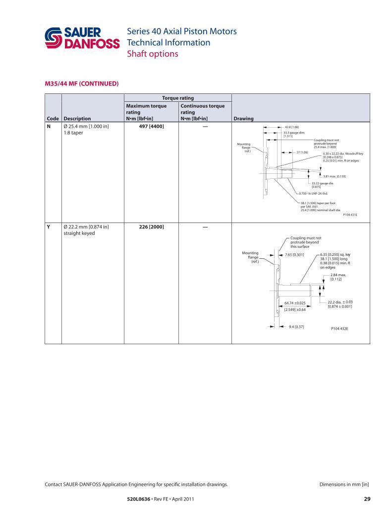
m35/44 mf (ContinueD)
Code Description
torque rating
Drawing
maximum torque ratingN•m [lbf•in]
Continuous torque ratingN•m [lbf•in]
n Ø 25.4 mm [1.000 in]1:8 taper
497 [4400] —
0.750-16 UNF-2A thd.
22.22 gauge dia.[0.875]
38.1 [1.500] taper per footper SAE J50125.4 [1.000] nominal shaft dia.
3.81 max. [0.150]
6.30 x 22.22 dia. Woodruff key[0.248 x 0.875]0.25 [0.01] min. R on edges
33.3 gauge dim.[1.311]
42.8 [1.68]
27 [1.06]
Coupling must notprotrude beyond25.4 max. [1.000]
Mountingflange
(ref.)
P104 431E
y Ø 22.2 mm [0.874 in] straight keyed
226 [2000] —
C oupling must not protrude beyond this sur fac e
7.65 [0.301]
22.2 di a. [0.874 ± 0.001]
2.84 ma x. [0.112]
6.35 [0.250] sq. ke y 38.1 [1.500] long 0.38 [0.015] min. R on edges
64.74 ±0.025
[2.549] ±0.64
9.4 [0.37]
Mounting flange
(ref.)
P104 432E
± 0.03
520L0636 • Rev FE • April 201130
Series 40 Axial Piston MotorsTechnical InformationShaft options
Contact SAUER-DANFOSS Application Engineering for specific installation drawings. Dimensions in mm [in]
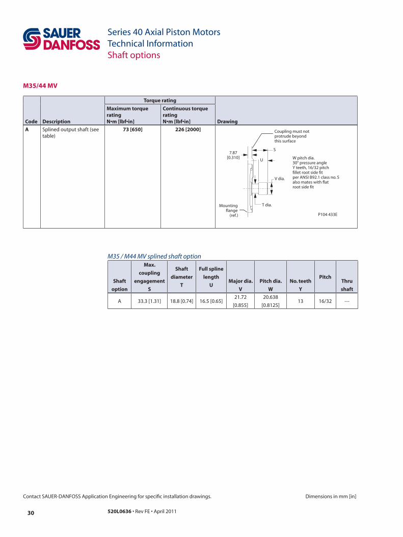
m35/44 mv
Code Description
torque rating
Drawing
maximum torque ratingN•m [lbf•in]
Continuous torque ratingN•m [lbf•in]
a Splined output shaft (see table)
73 [650] 226 [2000]
T dia.
V dia.
W pitch dia.30° pressure angleY teeth, 16/32 pitchfillet root side fitper ANSI B92.1 class no. 5also mates with flatroot side fit
S
U
Coupling must notprotrude beyondthis surface
7.87[0.310]
Mountingflange
(ref.) P104 433E
shaft
option
max.
coupling
engagement
s
shaft
diameter
t
full spline
length
umajor dia.
v
Pitch dia.
w
no. teeth
y
Pitchthru
shaft
A 33.3 [1.31] 18.8 [0.74] 16.5 [0.65]21.72
[0.855]
20.638
[0.8125]13 16/32 ---
M35 / M44 MV splined shaft option

31520L0636 • Rev FE • April 2011
Series 40 Axial Piston MotorsTechnical InformationShaft options
Contact SAUER-DANFOSS Application Engineering for specific installation drawings. Dimensions in mm [in]
m46 mv
Code Description
torque rating
Drawing
maximum torque ratingN•m [lbf•in]
Continuous torque ratingN•m [lbf•in]
a, B, Splined output shaft (see table)
13 tooth 226 [2000] 13 tooth 73 [650]
W pitch dia.30° pressure angleY teeth, Z pitchfillet root side fitper ANSI B92.1 class no. 5also mates with flatroot side fit
V dia.
U Full Spline
S max.
T max. dia.
7.47 [0.294]
Mountingflange
(ref.)
Coupling must not protrudebeyond this surface
R
P104 434E
e, f, 15 tooth 362 [3200] 15 tooth 153 [1350]
D 19 tooth 460 [4070] 19 tooth 194 [1710]
J 25.4 [1.000]tapered shaft
— 497 [4400]
5.05 [0.199]
6.30 x 22.22 dia. woodruff key[0.248 x 0.875]1/8 taper [1.500 per foot]per SAE standard J50125.4 [1.000] nominal shaft dia.
37.62[1.481]
36.58 [1.440]max.
26.97[1.062]
9.17 gauge dim.[0.361]
Coupling must not protrudebeyond this surface
3/4 - 16 Thd.22.22 [0.875]gauge dia.
Mountingflange
(ref .)
P104 435E
shaft
option
shaft
extension
R
max.
coupling
engagement
s
shaft
diameter
t
full
spline length
u
major dia.
v
Pitch dia.
w
no.
teeth
y
Pitch
z
thru
shaft
A32.94
[1.297]
32
[1.26]
19.1
[0.75]
15.8
[0.62]
21.72
[0.855]
20.638
[0.8125]13 16/32 ---
B32.94
[1.297]
32
[1.26]
19.1
[0.75]
15.8
[0.62]
21.72
[0.855]
20.628
[0.8125]13 16/32 13T
E37.72
[1.485]
36.6
[1.44]
22.3
[0.88]
22.86
[0.90]
24.89
[0.980]
23.812
[0.9375]15 16/32 ---
F37.72
[1.485]
36.6
[1.44]
22.3
[0.88]
22.86
[0.90]
24.89
[0.980]
23.812
[0.9375]15 16/32 13T
D37.72
[1.485]
36.6
[1.44]
28.4
[1.114]
22.35
[0.88]
31.24
[1.230]
30.162
[1.1875]19 16/32 ---
M46 MV splined shaft option
520L0636 • Rev FE • April 201132
Series 40 Axial Piston MotorsTechnical InformationControl options
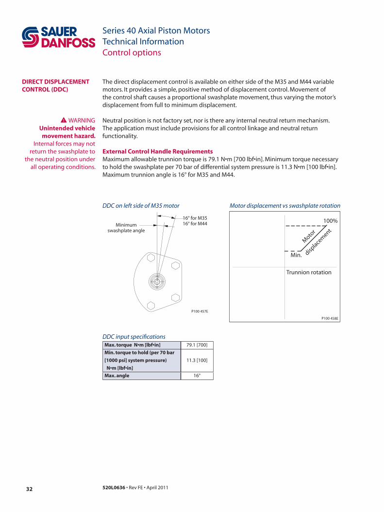
DiReCt DisPLaCement ContRoL (DDC)
The direct displacement control is available on either side of the M35 and M44 variable motors. It pro vides a simple, positive method of displacement control. Movement of the control shaft causes a propor tional swashplate movement, thus varying the motor’s displacement from full to minimum displacement.
Neutral position is not factory set, nor is there any internal neutral return mechanism. The application must include provisions for all control linkage and neutral return functionality.
external Control handle RequirementsMaximum allowable trunnion torque is 79.1 N•m [700 lbf•in]. Minimum torque necessary to hold the swash plate per 70 bar of differential system pressure is 11.3 N•m [100 lbf•in]. Maximum trunnion angle is 16° for M35 and M44.
DDC on left side of M35 motor Motor displacement vs swashplate rotation
Max. torque N•m [lbf•in] 79.1 [700]
min. torque to hold (per 70 bar
[1000 psi] system pressure)
N•m [lbf•in]
11.3 [100]
max. angle 16°
Minimumswashplate angle
16° for M3516° for M44
P100 457E
100%
Min.
Trunnion rotation
Moto
r
displace
ment
P100 458E
WWARNINGunintended vehicle
movement hazard. Internal forces may not
return the swashplate to the neutral position under
all operating conditions.
DDC input specifications

33520L0636 • Rev FE • April 2011
Series 40 Axial Piston MotorsTechnical InformationControl options
two‑Position hyDRauLiC ContRoL
Series 40 M46 variable displacement motors are equipped with a hydraulically controlled swashplate. The motor is spring biased toward maximum displacement. A hydraulic piston is used to shift the swashplate from maximum to minimum displacement. A single or two-line control can regulate the servo piston.
With the standard single-line control option, hydraulic pressure is supplied to the control port (X1) to shift the motor to minimum displacement. The opposite end of the displacement control piston internally drains to the motor case. The swashplate shifts with a minimum pressure of 13.8 bar [200 psi]. The bias spring returns the motor to maximum displacement when control pressure is removed.
The single-line control generally uses a customer supplied 2-position, 3-way control valve. Hydraulic pressure on the control piston must not exceed 27.6 bar [400 psi].
In applications which encounter frequent shifting on-the-go as part of the normal duty cycle, we recommend the optional two-line control. Applications with routine shifting from work range to travel range may not require the two-line control. to command minimum displacement, port control pressure to port X1 and drain port X2. To command maximum displacement, port control pressure to port X2 and drain port X1.
The two-line control generally uses a customer supplied 2-position, 4-way control valve. Hydraulic pressure on the control piston must not exceed 27.6 bar (400 psi).
Orifices in either (or both) the control valve supply and drain lines optimize the shift rate for either the single or two-line control. Contact your Sauer-Danfoss representative for additional information.
single line control two line control
Max. pressure on control 27.6 [400] 27.6 [400]
Min. pressure to shift 13.8 [200] 13.8 [200]
Control valve
(customer supplied)2-position / 3 way 2-position / 4-way
Input specifications bar [psi]
Port X1Control pressure supply
(for minimum displacement)
Port X2Control pressure supply
(for maximum displacement)
Top
Bottom P100
459
E
Single-line control Two-line control
M46 2-position hydraulic controls
520L0636 • Rev FE • April 201134
Series 40 Axial Piston MotorsTechnical InformationInstallation drawings
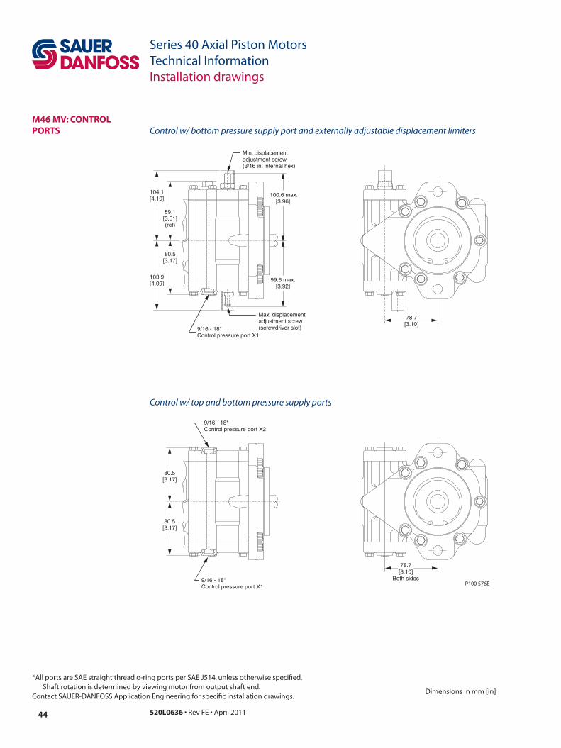
*All ports are SAE straight thread o-ring ports per SAE J514, unless otherwise specified. Shaft rotation is determined by viewing motor from output shaft end.
Contact SAUER-DANFOSS Application Engineering for specific installation drawings.Dimensions in mm [in]
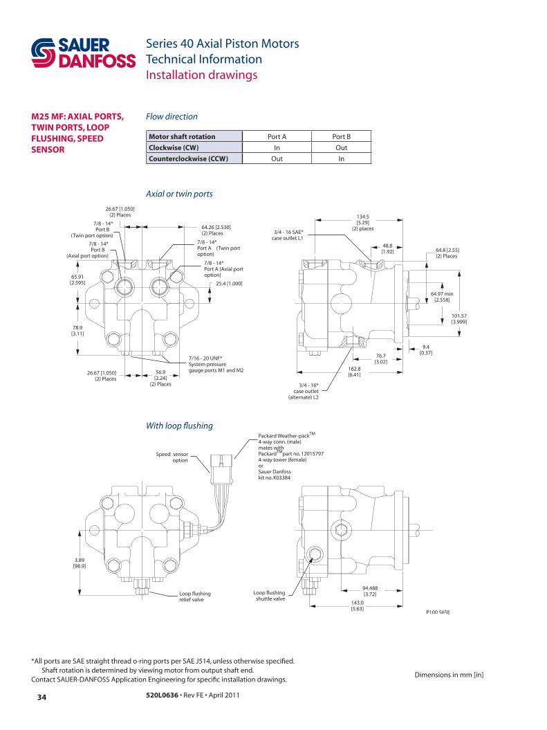
m25 mf: axiaL PoRts, twin PoRts, LooP fLushinG, sPeeD sensoR
motor shaft rotation Port A Port B
Clockwise (Cw) In Out
Counterclockwise (CCw) Out In
65.91 [2.595]
26.67 [1.050] (2) Places
7/8 - 14* Po rt A (T win po rt option)
7/8 - 14* Po rt B
(T win po rt option)
78.9 [3.11]
64.26 [2.530] (2) Places
26.67 [1.050] (2) Places
25.4 [1.000]
56. 9 [2.24]
(2) Places
64.8 [2.55] (2) Places
162. 8 [6.41]
134. 5 [5.29]
(2) places
64.97 mi n [2.558]
101.57 [3.999]
3/4 - 16 SAE* case outlet L1
76.7 [3.02]
9.4 [0.37]
48.8 [1.92]
7/16 - 20 UNF*System pressur e gauge por ts M1 and M2
3/4 - 16* case outlet
(alternate) L2
3.89 [98.9]
Lo op flushing relief v alv e
Lo op flushing shuttle v alv e
143.0 [5.63]
Speed sensor option
P ack ar d W eather-pack 4-w ay conn. (male) mates with P ack ard par t no . 12015797 4-w ay tower (f emale) or Sauer Danf oss k it no . K03384
7/8 - 14* Po rt A (Axial port option)
7/8 - 14* Po rt B
(Axial po rt option)
94.488 [3.72]
P100 565E
TM
TM
Axial or twin ports
With loop flushing
Flow direction

35520L0636 • Rev FE • April 2011
Series 40 Axial Piston MotorsTechnical InformationInstallation drawings
Dimensions in mm [in]
*All ports are SAE straight thread o-ring ports per SAE J514, unless otherwise specified. Shaft rotation is determined by viewing motor from output shaft end.
Contact SAUER-DANFOSS Application Engineering for specific installation drawings.
m25 mf: mountinG fLanGe
87.2[3.44]
(2) places
73.02[2.875]
(2) places
14.27 [0.562] dia.(2) places
CWCCW
P100 566E
m35/m44 mf: mountinG fLanGe
66.55 [2.620]Case drain - L1 and L2both sides
70.36[2.77]
(2) places
87.25[3.435]
(2) places14.27 dia.[0.562] (2) places
Approx. centerof gravity
CW
CCW
4.06[0.16]
P100 569E

520L0636 • Rev FE • April 201136
Series 40 Axial Piston MotorsTechnical InformationInstallation drawings
*All ports are SAE straight thread o-ring ports per SAE J514, unless otherwise specified. Shaft rotation is determined by viewing motor from output shaft end.
Contact SAUER-DANFOSS Application Engineering for specific installation drawings.Dimensions in mm [in]
m35/m44 mf: axiaL PoRts, twin PoRts, LooP fLushinG, sPeeD sensoR
77. 1 [3.04]
79. 5 [3.13]
71. 9 [2.83]
Po rt A
77. 7 [3.06]
(2) Places Po rt B
7/16 -20*System pressur e gauge po rt - M1
7/16 -20*System pressur e gauge po rt - M2
23. 9 [0.94]
(2) Places
Lo op flushing va lv e (option)
78. 2 [3.08]
1-1/16 -12* (2) places
154. 6 [6.08]
186. 3 [7.34]
92. 1 [3.63]
12. 8 [0.51]
99. 1 [3.90]
Lo op flushing shuttle va lv e (option)
Speed sensor option
Housing w/ optional speed sensing
105. 6 [4.16]
44. 5 [1.75] 71. 9
[2.83]
89. 7 [3.53]
1-1/16 -12* (2) places
7/8 -14* Case drain - L3
40. 1 [1.58]
(2) places
P ack ar d W eather-P ack 4-w ay conn. (male) mates with P ack ard par t no. 12015797 4-w ay tower (f emale) or Sauer-Danf oss ki t no . K03384
185. 4 [7.30]
186. 8 [7.335]
101.57[3.999]
9. 4 [0.37]
30. 5 [1.20]
7/16 -20* System pressur e gauge po rt - M1
7/16 -20* System pressur e gauge po rt - M2
23. 9 [0.94]
Lo op flushing Relief va lv e (option)
78. 2 [3.08]
Lo op flushing shuttle va lv e (option)
P100 567E
TM TM
motor shaft
rotationPort A Port B
Clockwise In Out
Counterclockwise Out In
Axial ports
Twin ports
Flow direction

37520L0636 • Rev FE • April 2011
Series 40 Axial Piston MotorsTechnical InformationInstallation drawings
Dimensions in mm [in]
*All ports are SAE straight thread o-ring ports per SAE J514, unless otherwise specified. Shaft rotation is determined by viewing motor from output shaft end.
Contact SAUER-DANFOSS Application Engineering for specific installation drawings.
m35/m44 mf: siDe PoRts, thRouGh shaft
186.3[7.34]
184.9[7.28]
17.8[0.70]
154.6[6.09]
161.3[6.35]
1-1/16 -12*(2) places
92.1[3.63]
12.8[0.51]
99.1[3.90]
Approx. centerof gravity
7/8 -14*Case drain - L2
67.3[2.65]
(2) places
89.7[3.53]
71.9[2.83]
77.7[3.06]
(2) places
65.9[2.60]
(2) places
7/8 -14*Case drain - L3
44.5[1.75]
PortB
Port A
Aux. shaft option
Auxiliary drive spline data:20.638 pitch diameter[0.8125]30° pressure angle13 teeth, 16/32 pitchfillet root side fitANSI B92.1-1790 class no.5also mates with flatroot side fit
161.3[6.35]
184.0[7.25]
218.29[8.594]1-1/16 -12*
(2) places
21.72[0.855]
21.1 [0.83]Full spline
length
36.8 max.[1.45]
Coupling must notprotrude beyondthis surface
6.3[0.25]
151.00[5.95]
7/8 -14*Case drain - L3
29[1.14]
(2) Places
67.3[2.63]
89.7[3.53]
71.9[2.83]
70.5[2.77]
50.813[2.000]
65.91[2.60]
1/2 -13 Thd.92 Min. Full Thd.
[23.3](2) places
67.3[2.63] 92.1
[3.63]12.8
[0.51]
99.1[3.90]
Approx. centerof gravity
7/8 -14*Case drain - L2
P100 568E
Side ports
Side ports with thru shaft

520L0636 • Rev FE • April 201138
Series 40 Axial Piston MotorsTechnical InformationInstallation drawings
*All ports are SAE straight thread o-ring ports per SAE J514, unless otherwise specified. Shaft rotation is determined by viewing motor from output shaft end.
Contact SAUER-DANFOSS Application Engineering for specific installation drawings.Dimensions in mm [in]
m35/m44 mv: twin PoRts
164.7[6.48]
96.4[3.80]
1-1/16 -12*Case outlet
1-1/16 -12*Port A
1-1/16 -12*Port B
35[1.38]
35[1.38]
95[3.74] 7.6
[0.301]
16° max.Disp.
min.Disp.
66.7[2.63]
12.6[0.50]
Port B Port A
9/16 -18*system pressuregauge Port M1
Displacementlimiter
9/16 -18*System pressure
gauge Port M2
92.2[3.63]
96.5[3.80]
80.5[3.17]
101.57[3.999]
P100 570E

39520L0636 • Rev FE • April 2011
Series 40 Axial Piston MotorsTechnical InformationInstallation drawings
Dimensions in mm [in]
*All ports are SAE straight thread o-ring ports per SAE J514, unless otherwise specified. Shaft rotation is determined by viewing motor from output shaft end.
Contact SAUER-DANFOSS Application Engineering for specific installation drawings.
m35/m44 mv: mountinG fLanGe, tRunnion ContRoL
CWCCW
125[4.92]
111.8[4.40]
70.4[2.77]
Control trunnionleft side
option L
Control trunnionright sideoption R
87.25[3.44]
73.03[2.875]
45°
19.01 [0.750](2) places
19.84[0 .781]
14.5 dia.[0.562]
(2) places
P100 571E
Trunnion control
520L0636 • Rev FE • April 201140
Series 40 Axial Piston MotorsTechnical InformationInstallation drawings
*All ports are SAE straight thread o-ring ports per SAE J514, unless otherwise specified. Shaft rotation is determined by viewing motor from output shaft end.
Contact SAUER-DANFOSS Application Engineering for specific installation drawings.Dimensions in mm [in]
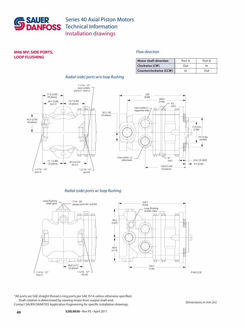
m46 mv: siDe PoRts, LooP fLushinG
motor shaft direction Port A Port B
Clockwise (Cw) Out In
Counterclockwise (CCw) In Out
72.6 min.[2.86]
101.6 dia. [4.000]
30 [1.18](2) places
228[8.98]
139.6 [5.50](2) places
9.7 [0.38]
22.61 [0 .890]
63.5 [2.50](4) places
71.6 [2.82](4) places
1-5/16 - 12*port B
82.6 [3.25](to L2)
1-5/16 - 12*port A
200.5[7.90]
Case outlet L2(alternate)
X1(ref.)
X2(ref.)
case outlet L1(opposite side)
1-1/16 - 12*case outlets
ports L1 and L2
71.1 [2.80](2) places
74.7 [2.94](2) places
68.1 [2.68](to L1)
1-5/16 - 12*Port B
1-5/16 - 12*Port A
229.7[9.04]
194.7[7.66]
Loop flushingshuttle valve
Loop flushingrelief valve
7/16 - 20*gauge ports M1 and M2
98.3[3.87]
80.9[3.19]
68.8 [2.71](2) places
P100 572E
Radial (side) ports w/o loop flushing
Radial (side) ports w/ loop flushing
Flow direction

41520L0636 • Rev FE • April 2011
Series 40 Axial Piston MotorsTechnical InformationInstallation drawings
Dimensions in mm [in]
*All ports are SAE straight thread o-ring ports per SAE J514, unless otherwise specified. Shaft rotation is determined by viewing motor from output shaft end.
Contact SAUER-DANFOSS Application Engineering for specific installation drawings.
m46 mv: axiaL PoRts, LooP fLushinG
1-1/16 - 12*port B
229.7[9.04]
Loop flushingshuttle valve
Loop flushingrelief valve
7/16 - 20*gauge ports M1 and M2
98.3[3.87]
80.9[3.19]
71.6 [2.82](2) places
42.4 [1.67](2) places
1-1/16 - 12*port A
63.5[2.50]
89.7 [3.53]w/o loopflushing
P100 573E
Axial ports w/ loop flushing

520L0636 • Rev FE • April 201142
Series 40 Axial Piston MotorsTechnical InformationInstallation drawings
*All ports are SAE straight thread o-ring ports per SAE J514, unless otherwise specified. Shaft rotation is determined by viewing motor from output shaft end.
Contact SAUER-DANFOSS Application Engineering for specific installation drawings.Dimensions in mm [in]
m46 mv: siDe PoRts, thRu shaft twin PoRts, LooP fLushinG
50.8[2.00]
(2) places
1/2 - 13 Thd.thru
(2) places
58.9[2.32]
(2) places
50.813[2.0005]ø
ø 21.717 [0.8550]
21.1 [0.83] Full Spline
20.638 [0.8125] pitch dia.30° pressure angle
13 teeth, 16/32 pitchfillet root side fit
per ANSI B92.1, class no. 5(also mates with flat
root side fit)
25.4[1.00]7.7
[0.303]
40.0 [1.57] max.
37.3 [1.47]
1-1/16 - 12*port B
68.5[2.69]
1-1/16 - 12*port A
29.7 [1.17](2) places
7/16 - 20*gauge ports M1 and M2
229.7[9.04]
Loop flushingshuttle valve
98.3[3.87]
Loop flushingrelief valve
13.49 dia. thru[0.531]
(2) places
199.6[7.86]
89.7 [3.53]w/o loopflushing
P100 574E
Side ports w/ thru shaft Radial (side) ported w/ loop flushingw/ thru shaft
Radial (twin) ports w/ loop flushing

43520L0636 • Rev FE • April 2011
Series 40 Axial Piston MotorsTechnical InformationInstallation drawings
Dimensions in mm [in]
*All ports are SAE straight thread o-ring ports per SAE J514, unless otherwise specified. Shaft rotation is determined by viewing motor from output shaft end.
Contact SAUER-DANFOSS Application Engineering for specific installation drawings.
m46 mv: mountinG fLanGe
82[3.23]
14.27 dia. thru[0.562](2) places
87.2[3.44]
(2) places
115.1[4.53]
73.7[2.90]
73.02[2.875]
(2) places
89.1[3.51] CWCCW
P100 575E
520L0636 • Rev FE • April 201144
Series 40 Axial Piston MotorsTechnical InformationInstallation drawings
*All ports are SAE straight thread o-ring ports per SAE J514, unless otherwise specified. Shaft rotation is determined by viewing motor from output shaft end.
Contact SAUER-DANFOSS Application Engineering for specific installation drawings.Dimensions in mm [in]
m46 mv: ContRoL PoRts
99.6 max.[3.92]
104.1[4.10]
100.6 max.[3.96]
89.1[3.51](ref)
80.5[3.17]
Min. displacementadjustment screw(3/16 in. internal hex)
Max. displacementadjustment screw(screwdriver slot)9/16 - 18*
Control pressure port X1
103.9[4.09]
80.5[3.17]
80.5[3.17]
9/16 - 18*Control pressure port X2
9/16 - 18*Control pressure port X1
78.7[3.10]
Both sides
78.7[3.10]
P100 576E
Control w/ bottom pressure supply port and externally adjustable displacement limiters
Control w/ top and bottom pressure supply ports
45520L0636 • Rev FE • April 2011
Series 40 Axial Piston MotorsTechnical InformationSchematics
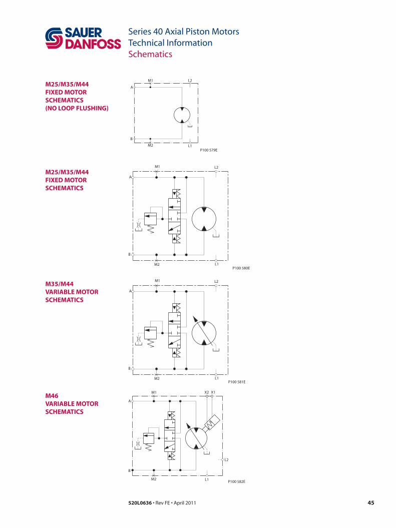
m25/m35/m44 fixeD motoR sChematiCs (no LooP fLushinG)
m25/m35/m44 fixeD motoR sChematiCs
m35/m44 vaRiaBLe motoR sChematiCs
m46 vaRiaBLe motoR sChematiCs
L1M2
B
L2M1
A
P100 579E
L1M2
B
L2M1
A
P100 580E
L1M2
B
L2M1
A
P100 581E
L1
L2
X1
M2
B
M1
A
X2
P100 582E

520L0636 • Rev FE • April 201146
Series 40 Axial Piston MotorsTechnical InformationNotes

47520L0636 • Rev FE • April 2011
Series 40 Axial Piston MotorsTechnical InformationNotes
520L0636 • Rev FE • April 2011
Local address:
Sauer-Danfoss GmbH & Co. OHGPostfach 2460, D-24531 NeumünsterKrokamp 35, D-24539 Neumünster, GermanyPhone: +49 4321 871 0Fax: +49 4321 871 122
Sauer-Danfoss ApSDK-6430 Nordborg, DenmarkPhone: +45 7488 4444Fax: +45 7488 4400
Sauer-Danfoss is a global manufacturer and supplier of high-quality hydraulic and electronic components. We specialize in providing state-of-the-art technology and solutions that excel in the harsh operating conditions of the mobile o� -highway market. Building on our extensive applications expertise, we work closely with our customers to ensure exceptional performance for a broad range of o� -highway vehicles.
We help OEMs around the world speed up system development, reduce costs and bring vehicles to market faster. Sauer-Danfoss – Your Strongest Partner in Mobile Hydraulics.
Go to www.sauer-danfoss.com for further product information.
Wherever o� -highway vehicles are at work, so is Sauer-Danfoss.
We o� er expert worldwide support for our customers, ensuring the best possible solutions for outstanding performance. And with an extensive network of Global Service Partners, we also provide comprehensive global service for all of our components.
Please contact the Sauer-Danfoss representative nearest you.
Products we o� er:
• Bent Axis Motors
• Closed Circuit Axial Piston Pumps and Motors
• Displays
• Electrohydraulic Power Steering
• Electrohydraulics
• Hydraulic Power Steering
• Integrated Systems
• Joysticks and Control Handles
• Microcontrollers and Software
• Open Circuit Axial Piston Pumps
• Orbital Motors
• PLUS+1™ GUIDE
• Proportional Valves
• Sensors
• Steering
• Transit Mixer Drives
Members of the Sauer-Danfoss Group:
Comatrolwww.comatrol.com
Schwarzmüller-Inverterwww.schwarzmueller-inverter.com
Turolla www.turollaocg.com
Hydro-Gear www.hydro-gear.com
Sauer-Danfoss-Daikinwww.sauer-danfoss-daikin.com
Sauer-Danfoss (US) Company2800 East 13th StreetAmes, IA 50010, USAPhone: +1 515 239 6000Fax: +1 515 239 6618
Sauer-Danfoss-Daikin LTD.Shin-Osaka TERASAKI 3rd Bldg. 6F1-5-28 Nishimiyahara, Yodogawa-kuOsaka 532-0004, JapanPhone: +81 6 6395 6066Fax: +81 6 6395 8585
w w w . s a u e r - d a n f o s s . c o m
Top Related