


Languages
Pages
Legal


14 July 2018 | TheStructuralEngineer
Structural engineering for the Elizabeth line
thestructuralengineer.orgDamage assessment and monitoring
Deborah LazarusMA (Cantab), CEng, FIStructE, FICE, FRSA
Consultant, Arup, London, UK
Damage assessment and monitoring for buildings on the Elizabeth line
Synopsis
The Elizabeth line, due to open in December 2018, crosses London from west to east. The Crossrail project to construct the Elizabeth line has seen 21km of twin-bored tunnels constructed under central London, with eight new stations built on this section.
The damage assessment and monitoring carried out comprised a signifi cant element of work in terms of the resources involved, both human and fi nancial. The background to this work was the experience from a number of tunnelling projects in London, probably most signifi cantly that from the London Underground Jubilee line extension. While all assets along the alignment were subject to the same process, the impact of the works around the stations and shafts was calculated to be greater than along the bored tunnels, and the extent of instrumentation and monitoring was correspondingly higher. Both automated
and manual methods were used,
with instrumentation installed and readily visible on many buildings in these areas throughout the duration of the works.
This paper looks at the damage assessment and monitoring of buildings around the stations, focusing in particular on the new station at Tottenham Court Road. It also provides an overview of the two very diff erent tunnel construction methods used on the project – the so-called tunnel boring machine (TBM) and sprayed concrete lining (SCL) methods – and describes how these lead to the ground movement that is the principal source of potential damage to the buildings.
Finally, the paper considers briefl y some of the lessons learned and how these might be applied to future urban tunnelling projects.
Hyuk-Il JungBSc, MEng, PE(Korea)
Associate, Arup, London, UK
NOTATION
BRE Building Research Establishment
SCL sprayed concrete lining
TAM tube à manchette
TBM tunnel boring machine
Introduction
The Elizabeth line, due to open in December 2018, crosses London from west to east. The project has seen 21km of twin-bored tunnels constructed under central London, with eight new stations built on this section of the line
(Figure 1). It should be noted at the outset that this was a major achievement: tunnelling below crowded streets was completed with little indication above ground, other than instrumentation on buildings, of what was happening below. Some aspects of how this
HA
MM
ERSM
ITH &
FULH
AM
ISLINGTON
CAMDEN
WESTMINSTER
KENSIN
GTON &
CHELSEA
BARKING & DAGENHAM
NEWHAM
TOWER HAMLETS
CITY OFLONDON
Tottenham Court Road Canary
WharfAbbey Wood
Custom House
Bond Street
Forest Gate
Manor Park
Seven Kings
Paddington
Farringdon Whitechapel
Woolwich
IlfordGoodmayes
Chadwell Heath
Maryland
Stratford
Liverpool Street
DistrictOverground
Hammersmith& City
CentralJubilee
Hammersmith& City
MetropolitanCircle
LutonGatwick
DLRCentralNorthern
OvergroundDLRJubileeCentral
Hammersmith& CityBakerloo
Circle
District NorthernCentral
Stansted
Hammersmith& City
Southend
MetropolitanCircle
DLRDLR
DLRJubilee
was achieved are described below.The construction of tunnels, even using
the most modern machinery and control methods, still results in some volume loss and corresponding ground movement. The impact of this movement on the assets, both above and below ground, can be assessed to varying levels of accuracy and the likely degree of damage predicted.
Damage assessment followed the process set out in Crossrail Information Paper D121 and relevant Crossrail Civil Engineering Design Standards, which in turn had been developed from earlier work on the London Underground Jubilee line and High Speed 1. This process covered assets including buildings (both low-rise masonry structures on shallow foundations and taller, framed structures on piled foundations), other structures and statutory services. Considering buildings alone, there were approx. 4000 buildings along the route, of which around 300 were listed.
CR
OS
SR
AIL
� Figure 1Central London section of Elizabeth line (bored tunnels and new underground stations shown in red)
TSE78_14-24_Monitoring damage.indd 14TSE78_14-24_Monitoring damage.indd 14 20/06/2018 17:1020/06/2018 17:10

15TheStructuralEngineer | July 2018
thestructuralengineer.orgStructural engineering for the Elizabeth line
This paper looks at the damage assessment and monitoring of buildings around the stations, focusing in particular on the new station at Tottenham Court Road; these included a number which were listed, some over 300 years old. Inevitably, for a project of this size and complexity, there are areas which have had to be omitted or covered only briefl y. Further information may be found in other publications, notably Crossrail Project: Infrastructure Design
and Construction2–5 which comprises four volumes of papers.
The paper also provides an overview of the two very diff erent tunnel construction methods used on the project and describes how these lead to the ground movement that is the principal source of potential damage to buildings.
The paper then explains the three-phase damage assessment method used on the project, including the approach used for heritage assessment and protection. The approach to mitigation of the impacts of ground movement is described, including the extensive monitoring of both the ground and assets along the alignment. The process of compensation grouting, which was used widely as mitigation around the stations, is explained. Examples of buildings around the new Tottenham Court Road station are then used to describe in more detail some of the mitigation measures adopted during construction, the monitoring installation and monitoring results.
Finally, the paper considers briefl y some of the lessons learned and how these might be applied to future urban tunnelling projects.
Tunnel construction methods
Two diff erent construction methods were used for the construction of Elizabeth line tunnels: tunnel boring machine (TBM) and sprayed concrete lining (SCL).
There are two diff erent types of TBM: the earth pressure-balanced TBM and slurry TBM. The selection of the appropriate TBM is dependent on the ground conditions. In the London Clay along most of the western part of the route, the earth pressure-balanced TBM was used; and for the tunnels driving through chalk, a slurry TBM was used. More detailed information can be found in specialist publications.
The TBM is equipped with a rotating cutter head (Figure 2) at the front of the machine’s steel shield body. The machine is designed to apply face pressure to the excavated ground face so as to balance earth and groundwater pressure until the (permanent) tunnel lining is constructed. Precast concrete segment rings are assembled at the back of the TBM to support the ground, and the TBM pushes against the ready-built ring to move forward.
SCL excavation (ground mining) is completely diff erent and is carried out with the use of excavators. The tunnel section is excavated for a short length (in London Clay, typically 1m), and shortly after the excavation, sprayed concrete is applied to the exposed ground to provide ground
support. The process is then repeated, with successive excavation and sprayed concrete application cycles. When the tunnel section is large and full-face excavation is considered unstable, it can be excavated by dividing it into several smaller sections to limit the size of unsupported ground.
On the Crossrail project, TBMs were used for the construction of the running tunnels (internal diameter 6.2m) between the stations, and SCL was used for the construction of station tunnels such as platforms, concourses (internal diameter approx. 9m) and cross-passages (internal diameter approx. 6m). The running tunnels are broadly 20–35m below ground level between the stations. At some of the stations, due to the various constraints in the construction programme, the TBM drove through the platform tunnels before SCL excavation started. In these locations, the bored tunnels were then subsequently enlarged by SCL to the fi nal profi le.
When a tunnel is excavated, the ground loses force equilibrium around the tunnel and thus the ground deforms. The face pressure (in the case of TBM) and tunnel lining (segment lining or SCL) provide support to the ground, which can limit the ground movement, but in soft ground such as London Clay (as opposed to rock), it is not possible to construct tunnels with zero
Damage assessment and monitoring
� Figure 2TBM cutter head, seen on two machines (named Ada and Phyllis) at Western Portal at start of tunnelling
� Figure 3Settlement above advancing tunnel6
FR
OM
: SO
IL M
OV
EM
EN
TS
IND
UC
ED
BY
TU
NN
ELL
ING
AN
D T
HE
IR E
FF
EC
TS
ON
PIP
ELI
NE
S, P
.B. A
TT
EW
ELL
, J. Y
EA
TE
S,
A.R
. SE
LBY,
CO
PY
RIG
HT
(19
86
) B
LAC
KIE
, RE
PR
OD
UC
ED
BY
PE
RM
ISS
ION
OF
TA
YLO
R &
FR
AN
CIS
BO
OK
S U
K
CR
OS
SR
AIL
TSE78_14-24_Monitoring damage.indd 15TSE78_14-24_Monitoring damage.indd 15 20/06/2018 17:1020/06/2018 17:10

Damage assessment and monitoringStructural engineering for the Elizabeth line
16 July 2018 | TheStructuralEngineer
thestructuralengineer.org
ground movement. This is due to the fact that deformation of the ground moves ahead of the excavation face (Figure 3)6, and also that there is always a time gap between the excavation and the construction of the lining, resulting in further ground movement.
Global best practice widely accepts that tunnelling-induced ground movements in soft ground can be estimated by assuming the settlement trough fi ts the Gaussian probability curve (perpendicular to the tunnel drive) and the cumulative probability curve (parallel to the tunnel drive). The buildings are assumed to deform following the predicted ground settlement trough (known as the ‘greenfi eld’ settlement profi le).
Movements along the tunnel alignment were generally predicted to be small, with correspondingly minor impacts on buildings. This correlated with the results recorded during the works; volume losses (Figure 4), particularly on the western drive (between Paddington and Farringdon) through London Clay, were generally lower (<0.5%) than the fairly conservative value of 1% assumed in the damage assessment calculations. Around the stations, the predicted values were higher; horizontal movements around the deep excavations were greater than those around the bored tunnels, and the larger platform tunnels and cross-passages were constructed using SCL techniques which also produce larger movements. Volume losses for SCL works were assumed to be 1.5% for the purposes of assessment. Further explanation of volume loss can be found in Burland7.
Classifi cation and assessment of building damage
Building damage classifi cation
While the focus of this paper is ‘damage’, it is worth considering what is meant by this term. Damage is a highly subjective and often emotive subject; in relation to buildings, this is perhaps the case particularly where the perception is that the damage has been caused by the actions of others. It may relate to aesthetics, to function and serviceability – the serviceability limit state – or in more extreme cases of structural damage (with a possible risk of instability) – the ultimate limit state. Most buildings experience some degree of cracking at some stage, often in fi nishes, but might not be regarded as ‘damaged’.
On the Crossrail project, it was recognised at the outset that the works would result in some degree of ground movement and that some damage was predictable – often seen as cracking, but with the potential for other
consequences such as jamming of doors or windows. The classifi cation of damage followed the procedure set out in Burland et
al.8 and Mair et al.9. Engineers will be familiar with the so-called ‘Burland’ classifi cation described in BRE Digest 25110. For listed assets, an additional score was assigned to account for building sensitivity. Tables 1 and 2, reproduced from Crossrail Information Paper D121, show the values that were used to provide an overall risk level.
Damage assessment process
For the purposes of this paper, the process described is necessarily simplifi ed to some degree, but it is intended that suffi cient information is provided, together with appropriate references for further detail where required.
For all assets that were located within a zone such that they might be aff ected by the works, given in Crossrail Civil Engineering Design Standards Part 811 as those located within the 1mm settlement contour, a three-phase damage assessment process was set out as summarised below.
The standard methodology for building
damage assessment adopted on the Crossrail project refers to a number of research papers and the methodology used on projects such as the Jubilee line extension, which assumed that buildings behaved as elastic beams and moved as per greenfi eld ground movements. Full references are included in Crossrail Information Paper D121. The classifi cation is considered to be conservative for many of the buildings, as it is based on case studies of loadbearing masonry buildings on shallow foundations. Framed buildings are considered to be more robust, but this is not quantifi ed within the methodology. For buildings on piled foundations, an alternative methodology is adopted which considers settlements calculated at three diff erent levels along the length of the piles.
Phase 1
Simple criteria (predicted settlement from bored tunnels or from the excavations less than 10mm and predicted ground slope less than 1/500) were used to eliminate buildings subjected to minimal eff ects. This set the limiting criterion as Damage Category 1
� Figure 4Defi nition of volume loss
W Figure 5Elastic beam model for buildings
TSE78_14-24_Monitoring damage.indd 16TSE78_14-24_Monitoring damage.indd 16 20/06/2018 17:1120/06/2018 17:11

Damage assessment and monitoringStructural engineering for the Elizabeth line
17TheStructuralEngineer | July 2018
thestructuralengineer.org
(‘very slight’) as defi ned by Rankin12, and these buildings were not subject to further assessment. This phase comprised an initial screening using upper bound parameters and assumed greenfi eld conditions.
Phase 2
In the next phase, a generic assessment was undertaken for buildings within the 10mm settlement contour. The greenfi eld settlement is imposed on buildings, i.e. it is still, conservatively, assumed that the settlement behaviour is not modifi ed by the stiff ness of the building, which is taken to be completely fl exible. In addition, the deformation due to horizontal ground movement is considered.
Figure 5 shows the simplifi ed elastic beam model for the simple case where a building (represented as a two-dimensional (2D) element) is located transverse to a tunnel below and entirely within the sagging zone of the settlement trough. In practice, of course, there was great variation in the orientation of buildings in relation to the tunnel alignment and, in some cases, the eastbound and westbound running tunnels were suffi ciently close so that the resulting settlement troughs had multiple sagging and hogging profi les due to the interference of the two troughs. A building’s response to the settlement is also infl uenced by the relative location of the building in relation to the sagging or hogging
TABLE 1: BUILDING DAMAGE CLASSIFICATION*1
Risk category Max tensile
strain (%)
Description of
degree of damage
Description of typical damage and likely form of repair for
typical masonry buildings
Approx. crack
width† (mm)
0 0.05 or less Negligible Hairline cracks
1 >0.05 and ≤0.075 Very slight Fine cracks easily treated during normal redecorations. Perhaps isolated slight fracture in building. Cracks in exterior brickwork visible upon close inspection
0.1 to 1
2 >0.075 and ≤0.15 Slight Cracks easily fi lled. Redecoration probably required. Several slight fractures inside building. Exterior cracks visible; some repointing may be required for weathertightness. Doors and windows may stick slightly
1 to 5
3 >0.15 and ≤0.3 Moderate Cracks may require cutting out and patching. Recurrent cracks can be masked by suitable linings. Repointing and possibly replacement of a small amount of exterior brickwork may be required. Doors and windows sticking. Utility services may be interrupted. Weathertightness often impaired
5 to 15 or a number of cracks greater than 3
4 >0.3 Severe Extensive repair involving removal and replacement of sections of walls, especially over doors and windows required. Windows and door frames distorted. Floor slopes noticeably. Walls lean or bulge noticeably, some loss of bearing in beams. Utility services disrupted
15 to 25 but also depends on number of cracks
5 Very severe Major repair required involving partial or complete reconstruction. Beams lose bearing, walls lean badly and require shoring. Windows broken by distortion. Danger of instability
Usually greater than 25 but depends on number of cracks
* Based on work of Burland et al. (1977)8 and includes typical maximum tensile strains for the various damage categories (column 2) used in Phase 2 settlement analysis† Crack width is only one aspect of damage and should not be used on its own as a direct measure of damage
TABLE 2: SCORING FOR SENSITIVITY ASSESSMENT OF LISTED BUILDINGS1
Criteria
Score Sensitivity of structure to ground
movements and interaction with
adjacent buildings
Sensitivity to movement of particular
features within building
0 Masonry building with lime mortar not surrounded by other buildings. Uniform facades with no particular large openings
No particular sensitive features
1 Buildings of delicate structural form or buildings sandwiched between modern framed buildings which are much stiff er, perhaps with one or more signifi cant openings
Brittle fi nishes, e.g. faience or tight-jointed stonework, which are susceptible to small movements and diffi cult to repair
2 Buildings which, by their structural form, will tend to concentrate all their movements in one location
Finishes which, if damaged, will have signifi cant eff ect on heritage of building, e.g. cracks through frescos
profi le of the settlement trough.Using the procedure described by Burland6
and Mair et al.9, the risk category for each building was assessed as defi ned in Table 1. For those where the category was assessed as less than 3, i.e. ‘negligible’, ‘slight’ or ‘very slight’, the assessment process was taken no further other than for:
buildings with a foundation level >4m, or >20% of the depth to the tunnel axis for those aff ected by the bored tunnels buildings on shallow foundations and within a distance from an excavation equal
to the greater of the excavated depth of superfi cial deposits or 50% of the total excavation depth listed buildings buildings where it was considered that further assessment was needed to determine whether protective works were required and/or what these should be.
Phase 3
In the next phase, buildings were considered individually rather than as part of an area analysed generically.
TSE78_14-24_Monitoring damage.indd 17TSE78_14-24_Monitoring damage.indd 17 20/06/2018 17:1120/06/2018 17:11

Damage assessment and monitoringStructural engineering for the Elizabeth line
18 July 2018 | TheStructuralEngineer
thestructuralengineer.org
The Phase 3 assessment was taken through several iterations as required, the intention being to understand whether increasing levels of accuracy would credibly reduce the risk of damage to an ‘acceptable’ level, with a risk category (or, for listed buildings, a total score) below 3. Refi nements included numerical modelling of the soil–structure interaction in conjunction with the tunnel excavation, and also more detailed assessment of the actual structure. Visual inspections were undertaken by structural engineers, often in conjunction with built heritage specialists for the listed buildings, to determine the form of the building and its condition. In a few cases, generally associated with buildings with retained facades but also where the visual inspection identifi ed other specifi c areas of concern, structural investigations were specifi ed.
The fi ndings from these surveys were included in the Damage Assessment Report produced for each individual building. Perhaps unsurprisingly, defects were identifi ed in some buildings which were felt
to need remedial works irrespective of the predicted impact of the Crossrail works; as a matter of professional practice, these were drawn to the attention of the building owner in a brief report, although in the majority of cases this prompted neither a response nor subsequent action by the building owner. Where it was felt that failure to carry out necessary repairs ahead of the works entailed some level of risk to the structure, these were undertaken by Crossrail.
These surveys were entirely separate from the defect surveys discussed below, which were undertaken on properties within the zone of infl uence of the works.
Listed buildings were assessed to determine their damage category in the same way as non-listed buildings. They were then, however, subject to a more detailed assessment process involving:
agreement of methodology through consultation with English Heritage (now Historic England) and local authorities a desk-based study (of available information taken from archives, etc.)
examination of damage assessment results for the listed buildings site visits (by structural engineers and/or heritage specialists to examine form, context (adjacent buildings), features, alterations where visible, repairs, condition) initial assessment (identifi cation of sensitive features, fi xtures, structure and their weaknesses) scoring of structural sensitivity to potential damage scoring of heritage sensitivity to potential damage identifi cation of buildings where further assessment, mitigation or other measures might be required.
Approaches to mitigation
General approaches
Given the number of properties within the zone of infl uence of the works (within the 1mm settlement contour) and the range of construction types, age and use, it was reasonable to anticipate some degree of pre-existing deterioration in at least some
E Figure 8TAM array in Tottenham Court Road station; radially located red lines indicate TAMs from compensation grout shafts (indicated as o on plan)
N Figure 6Compensation grouting shaft with TAM array installed14
� Figure 7Principles of compensation grouting15
CR
OS
SR
AIL
RE
PU
BLI
SH
ED
WIT
H P
ER
MIS
SIO
N O
F IN
ST
ITU
TIO
N O
F C
IVIL
E
NG
INE
ER
S, F
RO
M C
OM
PE
NS
AT
ION
GR
OU
TIN
G. I
NF
OR
MA
L D
ISC
US
SIO
N, R
.J. M
AIR
, W.J
. RA
NK
IN, R
.D. E
SS
LER
, AN
D P
.N. C
HIP
, P
RO
C. I
NS
T. C
IV. E
NG
. GE
OT
EC
H. E
NG
., 11
3 (
1), 1
99
5; P
ER
MIS
SIO
N
CO
NV
EY
ED
TH
RO
UG
H C
OP
YR
IGH
T C
LEA
RA
NC
E C
EN
TE
R, I
NC
TSE78_14-24_Monitoring damage.indd 18TSE78_14-24_Monitoring damage.indd 18 20/06/2018 17:1120/06/2018 17:11

Damage assessment and monitoringStructural engineering for the Elizabeth line
19TheStructuralEngineer | July 2018
thestructuralengineer.org
of these. Defect surveys as described in Crossrail Information Paper D121 were carried out in advance of the works to provide a record of the pre-works condition as a reference for agreeing any changes which could be ascribed subsequently to the works. Around the stations and shafts, where demolition of adjacent buildings was required, the impact of these preliminary works was assessed and defect surveys were undertaken prior to the commencement.
The starting point for mitigation was the commitment by Crossrail to keep predicted damage levels below Category 3, consistent with ‘moderate’. For listed buildings, the total score was the key parameter: this was the combination of the risk category and the sensitivity score, with this combined impact to be <3. A refi nement, however, was introduced during the works which recognised that no mitigation would be required in exceptional cases where there was a very high sensitivity score but negligible damage predicted. Here, it was this combined impact which was to be <3.
The primary and (preferred) means of mitigation was to control movement at source by controls on tunnelling and excavation with contractual limits on volume loss. Monitoring, both automated and manual, of asset and ground movements was widely used, with a range of instrumentation installed route-wide.
Ground treatment was also implemented where appropriate, although this in itself also has some impact, as described below.
In a limited number of cases, repairs and/or protection were indicated prior to the works, generally due to the pre-existing condition or the presence of sensitive elements such as stone ‘cantilever’ stairs, which in some instances were a cause for concern.
In many instances, the preferred solution, including for listed buildings, was to allow
cracking to occur and to allow repair with appropriate materials and methods once ground movements had ceased, as indicated by ongoing monitoring (see below). In the majority of cases, pre-emptive interventions were thought likely to be more intrusive and lead to greater impact on historic fabric, an approach which was agreed with the heritage authorities.
Ground treatment: compensation grouting
Where physical mitigation was indicated, the ambition was to make this non-intrusive wherever possible. Around stations and shafts, compensation grouting was adopted as the principal means of mitigation. While this did not control settlements to an absolute (target) value, it reduced the unmitigated movement and, more importantly, was used to limit the defl ection ratio (Fig. 5) to a value consistent with damage category 1 (very slight) or less, and a maximum ground slope of 1:1000.
Compensation grouting is described in more detail in other papers (e.g. Bezuijen, 2010)13, but a brief outline of the technique is included here. A grout shaft is installed at a specifi ed location to enable an array of tubes à manchette (TAMs) to be drilled out horizontally to lengths of up to 80m from the shaft. The tubes are installed radially at a number of depths within the shaft (Figure 6). Grout is injected through a selected TAM using two rubber packers which select the part of the tube where the grout will be injected. The grout is injected at high pressure so that the ground is fractured horizontally, then the grout penetrates through the fractured cracks and heaves the ground to compensate for settlements (Figure 7).
Although compensation grouting is intended to mitigate ground movement, the installation of the grout shaft and
TAMs themselves results in some ground settlement. While vertical ground movements due to the installation of the shaft are insignifi cant, the TAM installation process can cause settlement, in some cases of a magnitude of 10–20mm, infl uenced by both ground conditions and also the installation method. Settlements may also be larger in the zone closer to the shaft where the density of TAMs is much higher (see the red radial lines near the compensation shafts in Figure 8). This initial settlement is later compensated for by injecting grout through the TAMs before the main tunnel construction work starts, although this process, known as ‘priming’, can itself result in ground heave in excess of that anticipated.
While the grout process might be thought of as a continuous reactive process, the reality is not a smooth re-levelling, but rather a series of small step changes. Where settlements are predicted, the ground may also be lifted in advance by a ‘jacking’ process. The movements can be tightly controlled using a series of hydraulic levelling cells (Figure 9) generally installed in the basement of a building – or more accurately a group of basements nearby.
Further information on implementation of the process is provided in the case studies below.
Mitigation in buildings
The general approach to mitigation has been described above, i.e. minimising physical intervention where possible, in conjunction with monitoring of buildings. This resulted in a relatively low level of building works, complemented by site visits when concerns were raised either by building owners/occupants or by unexpected trends in monitoring results.
Works included application of fi lm to windows in a small number of buildings � Figure 9
Monitoring techniques
a) Invar scale on building facade – used for precise manual levelling
b) Prism on building facade – part of automated monitoring installation using Automated Total Stations
c) Hydraulic levelling cell – part of automated monitoring installation used to control building slopes
TSE78_14-24_Monitoring damage.indd 19TSE78_14-24_Monitoring damage.indd 19 20/06/2018 17:1120/06/2018 17:11
Damage assessment and monitoringStructural engineering for the Elizabeth line
20 July 2018 | TheStructuralEngineer
thestructuralengineer.org
where there were concerns that movements might lead to breakages, and a number of ‘protection’ schemes for elements such as stone ‘cantilever’ stairs where it was considered from inspections that there was, albeit low, some risk of collapse. In these cases, a structure was designed to be in position in the event that there was a collapse, but it was installed initially without contact to avoid imposing stresses into the element.
Repairs were carried out prior to the works in some buildings where defects were identifi ed which required rectifi cation more urgently. There were also repairs implemented during construction in some cases, even where it was not clear that the Crossrail works were the contributory factor: the overriding principle was to mitigate risk as far as reasonably possible.
Monitoring
Monitoring of both buildings and the ground was undertaken extensively across the project as part of the asset protection strategy. This provided information on when and how contingency measures should be adopted.
It confi rmed that the ground and the assets were behaving as anticipated. It also both provided information for design verifi cation and allowed construction control, providing confi rmation that excavations were being implemented in a controlled manner.
Techniques used included manual monitoring using studs and Invar calibrated scales (Fig. 9a); automated monitoring of prisms (Fig. 9b); hydrostatic levelling cells (Fig. 9c) and tiltmeters; and, at a later stage, satellite technology to look at ground movements in specifi c areas. This is an area where there are continuing developments and some changes might be anticipated for subsequent projects.
As is common practice, a ‘traffi c light’ system of trigger levels was adopted: green (proceed, no issues), amber (monitor more frequently, review calculations and start implementing contingency measures if trends continue) and red (a value not to be exceeded; in cases where this occurs, measures to be implemented to prevent further movements, with work suspended).
Amber values are close to those calculated from analysis, while red levels should be based upon an acceptable ‘damage’ criteria.
In many cases, as for other movement monitoring, it is trends that are important and any obvious cause which might underlie the increased movement should be investigated.
Case studies
Buildings around the new Tottenham Court
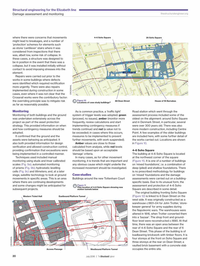
Road station which went through the assessment process included some of the oldest on the alignment: around Soho Square and in Denmark Street, in particular, several were over 300 years old. There was also more modern construction, including Centre Point. A few examples of the older buildings are included here, with some further detail of the works carried out. Locations are shown in Figure 10.
4–6 Soho Square
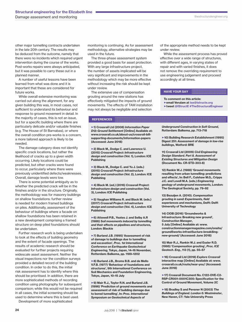
The building at 4–6 Soho Square is located at the northwest corner of the square (Figure 11). It is one of a number of buildings on ‘mixed foundations’, i.e. a combination of deep (piled) and shallow foundations. There is no prescribed methodology for buildings on ‘mixed’ foundations and the damage assessments were carried out on a building-specifi c basis. Due to its unusual form, the assessment and protection of 4–6 Soho Square are described in some detail.
The original building fronting Soho Square (Figure 12) is linked to 6 Dean Street on the west side. It was originally constructed as a warehouse c.1801–04 for John Trotter, ‘store-keeper general’ for army supplies during the Napoleonic wars. The warehouses were altered in 1816, when Trotter converted them into a ‘bazaar’. The shop front and ground-fl oor level were reconstructed c.1890. At that time, there was an open area between the rear of 4–6 Soho Square and the rear of 6 Dean Street. This phase of the building is of loadbearing brickwork with timber fl oors. It is four storeys at the front on Soho Square and three storeys at the rear on Dean Street; a vaulted brick basement with a concrete slab occupies the entire site.
� Figure 10Locations of case study buildings16
4–6 Soho Square 26 Soho Square
88 Dean Street House of St Barnabas
S Figure 11Plan location of 4–6 Soho Square showing new station tunnels below
Western Ticket Hall Eastbound Platform Tunnel
Access Passage Westbound Platform Tunnel
CR
OS
SR
AIL
CR
OS
SR
AIL
TSE78_14-24_Monitoring damage.indd 20TSE78_14-24_Monitoring damage.indd 20 20/06/2018 17:1120/06/2018 17:11

Damage assessment and monitoringStructural engineering for the Elizabeth line
21TheStructuralEngineer | July 2018
thestructuralengineer.org
Alterations took place in the mid-1980s in both the basement and at the upper levels. The open area between the buildings fronting Soho Square and Dean Street was infi lled to provide two wings of full-height accommodation to the north and south and a double-storey atrium in the centre. The two ‘wings’ are steel-framed with a mansard roof to the south wing and fl at roof to the north wing. A number of archive drawings were obtained, although these did not show full
construction details and attempts to locate any further information were not successful.
Figure 13 provides a schematic section through the building looking north, providing an overview of the diff erent foundation systems.
It was recognised at an early stage of the detailed design that the specifi c arrangement of construction in this building was particularly complex in terms of its likely response to ground movements; a detailed
assessment was therefore carried out. The new fl oors comprise precast concrete
units with an in situ topping. The units generally span across the width of the wings onto edge beams which, in turn, are supported on perimeter steel columns. The columns are tied together by transverse steel beams. The edge beams are connected to the party walls on the north and south sides. While the details on the archive drawings indicated that some provision for diff erential settlement between the buildings was intended, this would have been limited in magnitude and intrusive investigations showed that the tubes in which the threaded studs are located have been concreted up.
The implications of diff erential movement between 4–6 Soho Square and the adjacent buildings were therefore considered on the assumption that there was little, if any, provision to accommodate such movement.
The foundations of the original buildings are corbelled brick or stone strip and pad footings, although some walls were underpinned during construction of the 1980s link blocks. Foundations to the link blocks are piled, with the steel frame taken through the vaulted substructure. Trial pit information from the refurbishment shows strip footings under the original brick walls/vaults are typically founded at approx. 500mm below basement level, with various local deepenings at the original timber column positions to approx. 1500mm below basement level. The latter approximately matches the founding level of the pad
"THIS BUILDING WAS PARTICULARLY COMPLEX IN TERMS OF ITS LIKELY RESPONSE TO GROUND MOVEMENTS"
� Figure 13Schematic section through 4–6 Soho Square (east–west, taken through piled wing)
S Figure 12Front (east) elevation of 4–6 Soho Square
TSE78_14-24_Monitoring damage.indd 21TSE78_14-24_Monitoring damage.indd 21 20/06/2018 17:4020/06/2018 17:40
Damage assessment and monitoringStructural engineering for the Elizabeth line
22 July 2018 | TheStructuralEngineer
thestructuralengineer.org
footings under internal timber columns. Pile caps and ground beams for the new foundations are set just below the basement slab. Record drawings indicate that the walls adjacent to the new foundations were underpinned to a level approx. 1500mm to 2000mm below basement level, to enable the construction of the pile caps and ground beams. Crossrail archive information shows piles under the link blocks extend 22m below ground-fl oor level, although there is no record of pile diameters.
While it was accepted that the risk of some minor cracking to 4–6 Soho Square could not be eliminated, neither signifi cant cracking of
the walls nor of fl oor slabs and fi nishes were acceptable impacts in terms of damage to the structure and to its heritage value. Hence, it was concluded that mitigation measures were required, with any minor defects being repaired once movements had ceased.
The Phase 3 assessment of 4–6 Soho Square assigned a total score of 3 to the building, looking at the most onerous construction stages for critical sections through the building. This resulted in the adoption of compensation grouting as a protective measure to reduce the magnitude of ground movements, generally allowing a reduced damage category of 1 to be assigned to the building. This is consistent with possible crack widths of up to 1mm. The grouting was needed to address both diff erential movements between the piled and non-piled elements within the building, and also those between the piled elements and the party walls, recognising that the latter are also part of the adjoining buildings and thus subject to separate control. Grout shafts around Soho Square are indicated in Fig. 8, together with the TAM arrays from each. As part of the mitigation, compensation grouting could be used to control the movements of those parts of the structure on ground-bearing foundations, as was adopted commonly for buildings around the stations.
Although grouting was not used to control pile movements, in order to maximise coverage it was proposed, unusually, that the grout TAMs would be ‘threaded’ through the piled areas, requiring more accurate TAM positioning but off ering greater control
of ground movements. This also allowed grouting below the piled areas should this be necessary; again, while this was not a measure commonly utilised, it was decided after careful review that this would be instigated if diff erential settlements between these and the ground-bearing areas exceeded the ‘trigger’ level of 5mm specifi ed in the Specifi cation for Control of Ground Movements17. The same trigger level was specifi ed for diff erential movements between the piled areas and the adjoining buildings, namely 3 and 7 Soho Square and 5 Dean Street. In the event, these triggers were not reached and no compensation grouting was required in the piled areas.
Settlement of the foundations to the party walls and the areas of slab adjacent was controlled by the grouting arrays below the neighbouring buildings. It was therefore essential to control the grouting process for all these buildings as a single unit and instrumentation was arranged accordingly. It was recognised there was still some risk that, in the basement areas below the piled wings, it might not be possible to mitigate the movements fully by compensation grouting; it was therefore accepted that some cracking could occur.
Compensation grouting was also used to control the diff erential settlements along the party wall lines to avoid damage to the connections between the party walls and the 1980s framed structures. In the absence of eff ective allowance in the construction details for diff erential movement, it was necessary to ensure that there was very specifi c control
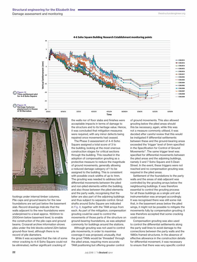
� Figure 14Time–settlement plot for 4–6 Soho Square
S Figure 15Heritage features: plasterwork in House of St Barnabas
TSE78_14-24_Monitoring damage.indd 22TSE78_14-24_Monitoring damage.indd 22 20/06/2018 17:1320/06/2018 17:13

Damage assessment and monitoringStructural engineering for the Elizabeth line
23TheStructuralEngineer | July 2018
thestructuralengineer.org
of the compensation grouting in order to minimise the impact of the predicted ground movements on the various elements of the building and its neighbours.
The following additional measures were undertaken to minimise ground movements at source as far as practicable, using controls on construction:
A volume-loss control zone, where a lower volume-loss target is set, was introduced for the eastbound running tunnel. During construction, the TBM was driven with tighter face-pressure control when driving through the volume loss control zone. Volume loss was minimised during construction of the three adjacent station tunnels that aff ect settlement of the buildings. This was achieved by sequential excavation of the tunnel sections so limiting the size and the length of unsupported ground at the excavation face. Ground movements resulting from construction of the Western Ticket Hall were carefully controlled by minimising the defl ection of the embedded wall.
Specifi c instrumentation was installed on the outside and inside of 4–6 Soho Square and the adjoining buildings to allow monitoring to be undertaken as part
of the construction contract. This was for control of the compensation grouting process and movements of the building. This instrumentation comprised hydraulic levelling cells in the basement with prisms, Building Research Establishment (BRE) studs and Invar scales on the external facades. Tiltmeters were also installed on internal columns. Figure 14 shows the time–settlement plot for the BRE studs at ground-fl oor level. This provides some indication of the monitoring data obtained during the project; such plots enabled the impact of particular construction activities to be assessed.
During the course of the works, no more than hairline cracking (consistent with damage category <1) was identifi ed. Given the works (structural and non-structural) being undertaken in the building concurrently with the Crossrail works, it was not possible to be defi nitive as to causation. It may be concluded that the mitigation measures adopted, namely compensation grouting and specifi c construction controls, prevented unacceptable levels of cracking being experienced during the course of the works. Monitoring also suggested that that there was no noticeable diff erence in response to ground movements between the piled and non-piled areas of the building.
While this was an unusually complex structure, the process described provides an overview of the extent of assessment and monitoring required to comply with Crossrail Ltd’s obligations to safeguard the assets along the alignment.
The House of St Barnabas (1 Greek Street)
The House of St Barnabas is a Grade 1 listed building. Internally it has some very fi ne plasterwork (Figure 15) and it is acknowledged as a fi ne example of a Georgian interior; Pevsner18 describes it as ‘one of the best and best-preserved mid-C18 houses in London’. Located at the east end of Tottenham Court Road station, it was aff orded special protection, with the appointment of separate heritage specialists, extensive pre-works condition surveys and monitoring installations both internally and externally. Pre-works mitigation included some repairs to brickwork and plaster and the installation of a protection frame below the fi ne open-well cantilever stair staircase.
26 Soho Square
Immediately to the north of the House of St Barnabas, the building at 26 Soho Square is Grade 2* listed. It also contains decorative plasterwork and another fi ne staircase (Figure 16). A protection structure was installed below the stairs until such time as ground movements were shown from the monitoring to have diminished to the specifi ed level (<2mm per year).
Both here and in the House of St Barnabas, there was clearance between the protection structure and the staircase throughout, and no further works were required.
88 Dean Street
The building at 88 Dean Street, also Grade 2* listed, showed signs of past movement both externally and internally. Of most concern was the pronounced outward lean on the front elevation, visible from the street and confi rmed by accurate survey. While investigations confi rmed that the facade was restrained by the internal fl oors, the cause of the movement remained unconfi rmed and there was some concern as to potential stability even with the very small ground movements predicted. Accordingly, it was decided that a scaff old structure would be erected externally, separated from the facade but designed to hold it in the event of major movements.
The facade was monitored and periodic inspections were carried out. In addition, some repairs were carried out while the scaff old was in place to improve the integrity of the facade.
Conclusions and lessons learned
The damage assessment process carried out followed that set out in Crossrail Information Paper D121, which was established at the start of the works, and was itself derived from
"A PROTECTION STRUCTURE WAS INSTALLED BELOW THE STAIRS"
� Figure 16Heritage features: stone staircase in 26 Soho Square (protection structure seen below)
TSE78_14-24_Monitoring damage.indd 23TSE78_14-24_Monitoring damage.indd 23 21/06/2018 14:1121/06/2018 14:11
Damage assessment and monitoringStructural engineering for the Elizabeth line
24 July 2018 | TheStructuralEngineer
thestructuralengineer.org
other major tunnelling contracts undertaken in the late 20th century. The results may be deduced from the outcome, namely that there were no incidents which required urgent intervention during the course of the works. Post-works repairs were always anticipated, but it was possible to carry these out in a planned manner.
A number of useful lessons have been learned from what was done and it is important that these are considered for future works.
While overall extensive monitoring was carried out along the alignment, for any given building this was, in most cases, not suffi cient to understand its behaviour and response to ground movement in detail. In the majority of cases, this is not an issue, but for a specifi c building where there are particularly delicate and/or valuable fi nishes (e.g. The House of St Barnabas), or where the overall condition pre-works is a concern, a more tailored approach is likely to be needed.
The damage category does not identify specifi c crack locations, but rather the likelihood of cracks up to a given width occurring. Likely locations could be predicted, but other cracks were found to occur, particularly where there were previously unidentifi ed defects/weaknesses. Overall, damage levels were low.
There is some potential ambiguity as to whether the predicted crack will be in the fi nishes and/or in the structure. Originally, the methodology was for masonry buildings on shallow foundations: further review is needed for modern framed buildings on piles. Additionally, assessment of the behaviour of buildings where a facade on shallow foundations has been retained in a new development comprising a framed structure on deep piled foundations should be undertaken.
Further research work is being undertaken to look at the eff ects of building geometry and the extent of facade openings. The results of academic research should be evaluated for further projects requiring widescale asset assessment. Neither the visual inspections nor the condition surveys provided a detailed record of the building condition. In order to do this, the initial risk assessment has to identify where this should be prioritised. In addition, there are more sophisticated methods of recording condition using photography for subsequent comparison; while this would not be required in all cases, the initial screening should be used to determine where this is best used.
Development of more sophisticated
monitoring is continuing. As for assessment methodology, alternative strategies may be used in the future.
The three-phase assessment system provided a good basis for asset protection. With any large infrastructure project, the number of assets implicated will be very signifi cant and improvements in the methodology which may be more eff ective without increasing the risk should be kept under review.
The extensive use of compensation grouting around the new stations has eff ectively mitigated the impacts of ground movements. The eff ects of TAM installation may not always be negligible and selection
of the appropriate method needs to be kept under review.
While the assessment process has proved eff ective over a wide range of structures, with diff erent ages, in varying states of repair and with varied fi nishes, it does not remove the overriding requirement to use engineering judgement and proceed accordingly at all times.
REFERENCES
E1) Crossrail Ltd (2008) Information Paper
D12: Ground Settlement [Online] Available at:
www.crossrail.co.uk/about-us/crossrail-bill-
supporting-documents/information-papers
(Accessed: June 2018)
E2) Black M., Dodge C. and Lawrence U.
(2015) Crossrail Project: Infrastructure
design and construction (Vol. 1), London: ICE
Publishing
E3) Black M., Dodge C. and Yu J. (eds.)
(2015) Crossrail Project: Infrastructure
design and construction (Vol. 2), London: ICE
Publishing
E4) Black M. (ed.) (2016) Crossrail Project:
Infrastructure design and construction (Vol.
3), London: ICE Publishing
E5) Vaughan Williams R. and Black M. (eds.)
(2017) Crossrail Project: Infrastructure
design and construction (Vol. 4), London: ICE
Publishing
E6) Attewell P.B., Yeates J. and Selby A.R
(1986) Soil movements induced by tunnelling
and their eff ects on pipelines and structures,
London: Blackie
E7) Burland J.B. (1995) ‘Assessment of risk
of damage to buildings due to tunnelling
and excavation’, Proc. 1st International
Conference on Earthquake Geotechnical
Engineering, Tokyo, Japan, 14–16 November,
Rotterdam: Balkema, pp. 1189–1202
E8) Burland J.B., Broms B.B. and de Mello
V.F.B. (1977) ‘Behaviour of foundations and
structures’, 9th International Conference on
Soil Mechanics and Foundation Engineering,
Tokyo, Japan, 10–15 July
E9) Mair R.J., Taylor R.N. and Burland J.B.
(1996) ‘Prediction of ground movements and
assessment of risk of building damage due
to bored tunnelling’, In: Proc. International
Symposium on Geotechnical Aspects of
Underground Construction in Soft Ground,
Rotterdam: Balkema, pp. 713–718
E10) Building Research Establishment (1995)
Digest 251: Assessment of damage in low-rise
buildings, Watford: BRE
11) Crossrail Ltd (2009) Civil Engineering
Design Standard. Part 8. Assessment of
Existing Structures and Mitigation Design
(Document No. CR-STD-303-8)
12) Rankin W.J. (1988) ‘Ground movements
resulting from urban tunnelling: predictions
and eff ects’, In: Bell F., Culshaw M.G., Cripps
J.C. and Lovell M.A. (eds.) Engineering
geology of underground movements, London:
The Geological Society, pp. 79–92
13) Bezuijen A. (2010). Compensation
grouting in sand: Experiments, fi eld
experiences and mechanisms, Delft: Delft
University of Technology
14) CIOB (2016) ‘Groundworks &
Infrastructure: Breaking new ground’,
Construction Manager,
5 July [Online] Available at: www.
constructionmanagermagazine.com/onsite/
ground5works-infrast5ucture-break8ing-
new-ground/ (Accessed: June 2018)
15) Mair R.J., Rankin W.J. and Essler R.D.
(1995) ‘Compensation grouting’, Proc. ICE
Geotech. Eng., 113 (1), pp. 55–57
E16) Crossrail Ltd (2018) Explore Crossrail
interactive map [Online] Available at: www.
crossrail.co.uk/route/near-you/ (Accessed:
June 2018)
E17) Crossrail Document No. C122-OVE-C2-
RSP-CR001-0001C300: Specifi cation for the
Control of Ground Movement, Volume 2C
E18) Bradley S and Pevsner N (2003) The
Buildings of England. London 6: Westminster,
New Haven, CT: Yale University Press
HAVE YOUR SAY
To comment on this article:
Eemail Verulam at [email protected]
Etweet @IStructE #TheStructuralEngineer
TSE78_14-24_Monitoring damage.indd 24TSE78_14-24_Monitoring damage.indd 24 21/06/2018 14:1121/06/2018 14:11
Top Related