


Languages
Pages
Legal

D-Series Engine Overspeed
Shut Down Valves(Auto/Manual Bendix Types)
Selection, Application and Maintenance
Valve NumbersD45-AM D51-AM D57-AM
D64-AM D70-AM D80-AM
CE207 (21)
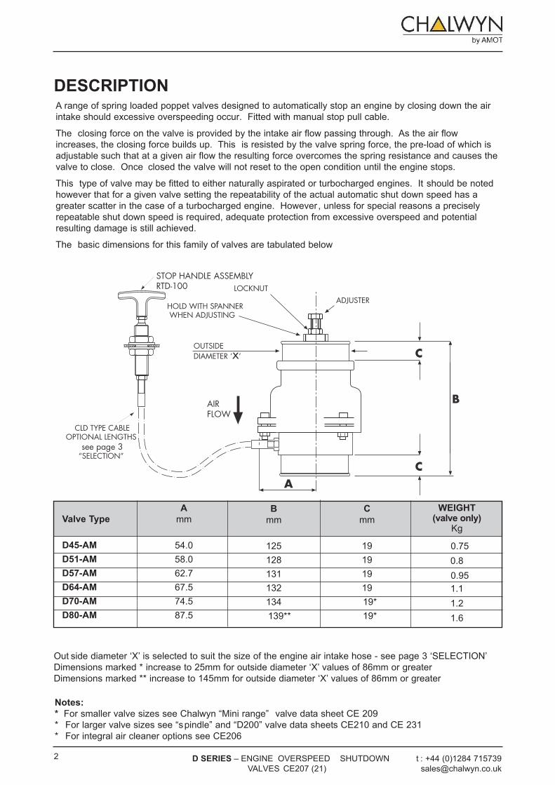
DESCriPTiONA range of spring loaded poppet valves designed to automatically stop an engine by closing down the air intake should excessive overspeeding occur. Fitted with manual stop pull cable.
The closing force on the valve is provided by the intake air flow passing through. As the air flow increases, the closing force builds up. This is resisted by the valve spring force, the pre-load of which is adjustable such that at a given air flow the resulting force overcomes the spring resistance and causes the valve to close. Once closed the valve will not reset to the open condition until the engine stops.
This type of valve may be fitted to either naturally aspirated or turbocharged engines. It should be noted however that for a given valve setting the repeatability of the actual automatic shut down speed has a greater scatter in the case of a turbocharged engine. However , unless for special reasons a precisely repeatable shut down speed is required, adequate protection from excessive overspeed and potential resulting damage is still achieved.
The basic dimensions for this family of valves are tabulated below
Notes:
* For smaller valve sizes see Chalwyn “Mini range” valve data sheet CE 209* For larger valve sizes see “spindle” and “D200” valve data sheets CE210 and CE 231* For integral air cleaner options see CE206
Valve Type
D45-AM
D51-AM
D57-AM
D64-AM
D70-AM
D80-AM
A
mm
54.058.062.767.574.587.5
B
mm
125128131132134139**
C
mm
1919191919*19*
WEiGHT(valve only)
Kg
0.750.80.951.11.21.6
Out side diameter ‘X’ is selected to suit the size of the engine air intake hose - see page 3 ‘SELECTION’ Dimensions marked * increase to 25mm for outside diameter ‘X’ values of 86mm or greater Dimensions marked ** increase to 145mm for outside diameter ‘X’ values of 86mm or greater
HOLD WITH SPANNER WHEN ADJUSTING
AIRFLOW
LOCKNUTADJUSTER
OUTSIDEDIAMETER ‘x’
AC
C
B
STOP HANDLE ASSEMBLYRTD-100
CLD TYPE CABLEOPTIONAL LENGTHS
see page 3 “SELECTION”
2 t : +44 (0)1284 715739 [email protected]
D SEriES – ENGINE OVERSPEED SHUTDOWN VALVES CE207 (21)
CABLE PArT NO
CLD-100
CLD-150
CLD-200
CLD-300
LENGTH (metres)
1.0
1.5
2.0
3.0
SELECTiON
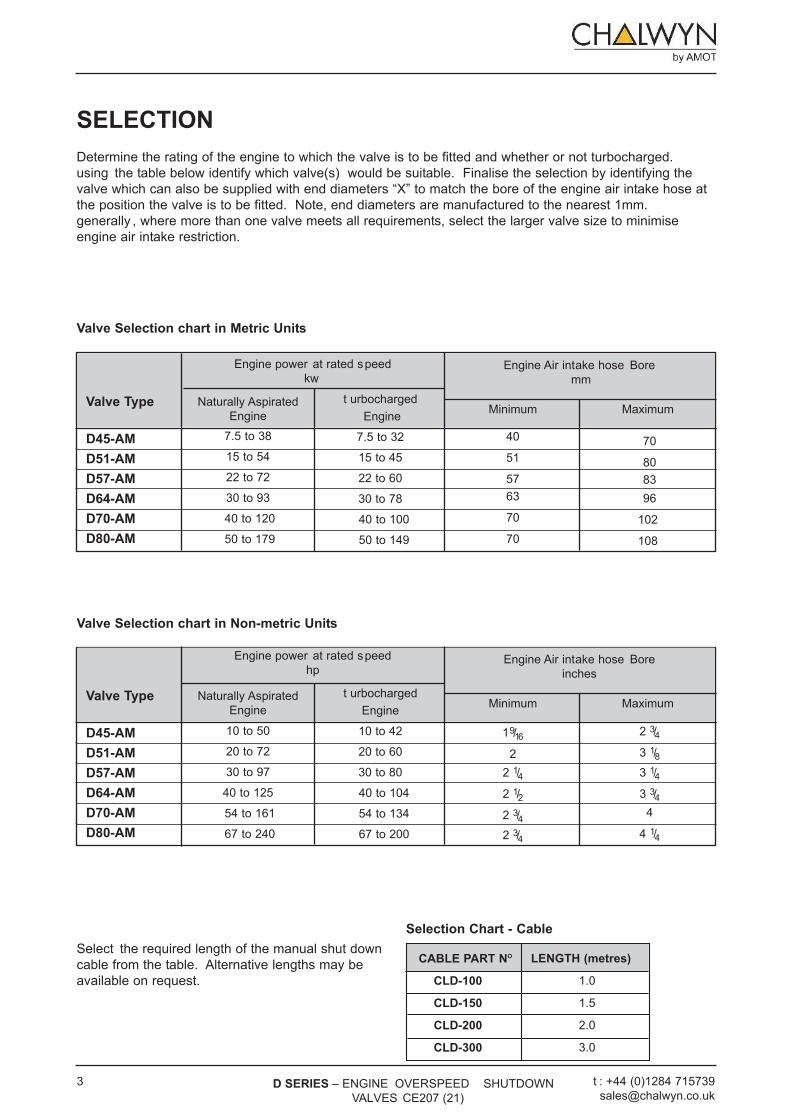
Determine the rating of the engine to which the valve is to be fitted and whether or not turbocharged.using the table below identify which valve(s) would be suitable. Finalise the selection by identifying thevalve which can also be supplied with end diameters “X” to match the bore of the engine air intake hose atthe position the valve is to be fitted. Note, end diameters are manufactured to the nearest 1mm.generally , where more than one valve meets all requirements, select the larger valve size to minimiseengine air intake restriction.
Valve Type
D45-AM
D51-AM
D57-AM
D64-AM
D70-AM
D80-AM
Naturally AspiratedEngine
7.5 to 38
15 to 54
22 to 72
30 to 93
40 to 120
50 to 179
t urbochargedEngine
7.5 to 32
15 to 45
22 to 60
30 to 78
40 to 100
50 to 149
Minimum
40
51
57 63
70
70
Maximum
70
80 83 96
102
108
Engine power at rated speed kw
Engine Air intake hose Bore mm
Valve Type
D45-AM
D51-AM
D57-AM
D64-AM
D70-AM
D80-AM
Naturally AspiratedEngine
10 to 50
20 to 72
30 to 97
40 to 125
54 to 161
67 to 240
t urbocharged Engine
10 to 42
20 to 60
30 to 80
40 to 104
54 to 134
67 to 200
Minimum
19/162
2 1/4 2 1/22 3/42 3/4
Maximum
2 3/4 3 1/8 3 1/4 3 3/4
4
4 1/4
Engine power at rated speedhp
Engine Air intake hose Boreinches
Valve Selection chart in Non-metric Units
Valve Selection chart in Metric Units
Selection Chart - Cable
Select the required length of the manual shut down cable from the table. Alternative lengths may be available on request.
t : +44 (0)1284 715739 [email protected]
3 D SEriES – ENGINE OVERSPEED SHUTDOWN VALVES CE207 (21)
4
1. Chalwyn auto/manual shut down valves are sup-plied complete with the manual stop cable and ‘t’handle fitted and adjusted. Do not separate thecable from handle or valve (see paragraph 8).
2. The shut down valve is designed for fitting asclose to the engine air intake manifold as possible.where an engine air intake flametrap is also fitted,the Chalwyn valve must always be positioned onthe upstream (air cleaner) side of the flametrap.These same requirements are generally applicableto both naturally aspirated and turbochargedengines, but in the case of a turbocharged enginethe following may be applicable.a) Insufficient space to fit between the
turbocharger and engine. in the case the valvemay be fitted upstream of the turbocharger.
b) The turbocharger air outlet temperature isexceptionally high (150°C plus). in this case fitthe valve downstream of the intercooler orupstream of the turbocharger.
3. Where more than one Chalwyn valve is fitted to anengine as in the case of an engine with multipleintake pipes, a balance pipe arrangement must beinstalled to connect the various intake pipes togeth-er downstream (engine side) of the shut downvalves. Typically balance pipe diameters should beabout 30% of the diameter of the intake pipes.
4. When fitting, ensure the direction of air flow:a) is in compliance with direction indicated on
the body.b) is between vertically downward and
horizontal.
5. The flexible cuffs at the inlet and outlet of thevalve should be of a re-inforced type, provideadequate support for the valve and preventexcessive vibration. If necessary, additionalsupport brackets mounted from the engine shouldbe considered.
t : +44 (0)1284 715739 [email protected]
D SEriES – ENGINE OVERSPEED SHUTDOW N VALVES CE207 (21)
FITTING
SAFETYWARNING
• Care should be taken when unpacking toprevent injury.
• Exhaust gases may cause permanentrespiratory problems, suffocation or death.Any exhaust systems should be piped out ofenclosed areas.
• Ensure that a hot engine has sufficientlycooled before commencing any work.
• Ensure that the engine is prevented frombeing started before commencing work.
• The D Valve should be located in a safe andeasily accessible position to prevent injury tothe operator due to moving parts or contactwith hot surfaces while setting the valve.
• Parts of the machinery on which workers arelikely to move about or stand to set theValve, should be designed and constructedin such a way as to prevent workers fromslipping, tripping or falling on or off theseparts.
• A risk assessment should be conductedbefore commencing work, to ensure that allhazards such as exhaust fumes, risks due tomoving parts, noise and hot surfaces havebeen eliminated or minimised.
• No special handling requirements apply tothe D Valve.
• Carefully read and fully understand theinstallation instructions beforecommencing work.
• Only competent personnel should installthe D valve.
• Wear appropriate Personal ProtectiveEquipment including safety footwear,safety glasses, thermal and oil resistantgloves and ear plugs.
NOTES

Once the Chalwyn valve is installed, adjustment of the overspeed trip setting is carried out using the adjuster and locknut (refer to diagrams). Basically rotating the adjuster clockwise will increase the engine speed at which automatic shut down occurs.
As supplied, the valve will be adjusted such that shut down will generally occur well below the engine high idle speed. To increase the speed at which automatic shut down occurs, proceed as follows:
t : +44 (0)1284 715739 [email protected]
5 D SEriES – ENGINE OVERSPEED SHUTDOWN VALVES CE207 (21)
•
ADJUSTMENTSAFETY
WARNINGWhen adjusting the D Valve, take care to ensure that contact with hot surfaces or entanglement in adjacent equipment is avoided.
NOTE• If a manual shut down cable assembly is fitted, ensure that excessive effort is not required to operate
the manual override.
‘T’ HANDLE
HANDLE LOCKNUT
STOP CABLE
UPPER LOCK NUT
LOWER LOCK NUT
HANDLE BODY
BULKHEAD or MOUNTING BRACKET
important Note.
The Chalwyn valve manual shut down control is intended for emergency use and for system checking only. Always retain the engine fuel stop system for routine engine shut down.
6. Particular care must be taken to ensure theintegrity of the intake pipework between theChalwyn valve and intake manifold. Ideally metalpipework should be used and any gaps kept asshort as possible,(taking into account any relativemovement) and closed by re-inforced hose. Thepossibility of a hose collapse on closure of the shutdown valve should be avoided.
7. Any engine crankcase breather connections intothe intake system between the Chalwyn valve andengine, or any internal crankcase breatherarrangement venting directly into the engine intakeports, must be sealed and replaced by an externalbreather system venting either to atmosphere or tothe intake system upstream of the shut down valve.External breather system kits for various enginetypes are available from Chalwyn.
8. Fit the ‘T ’ handle assembly RTD-100 through asuitable Ø20mm (3/4"dia) hole in a bulkhead ormounting bracket as follows. Release the handlelocknut. Remove the handle, handle locknut andupper locknut and washer. Thread handle bodythrough the bulkhead/bracket. Refit upper locknutand washer. Adjust lower and upper locknuts toposition handle and tighten. Refit handle locknutand handle. Tighten locknut.

6 t : +44 (0)1284 715739 [email protected]
D SEriES – ENGINE OVERSPEED SHUTDOWN VALVES CE207 (21)
MAINTENANCESAFETY WARNING
• When externally cleaning the valve ensure the engine is sufficiently cooled before commencing work,if cleaning a hot valve take extra care to avoid touching hot surfaces and to avoid entanglement inadjacent equipment.
• Take care not to trap fingers when making adjustments to the valve setting.• Equipment contains springs, during dismantling ensure that spring forces are safely removed.• When internally cleaning components with chemical agents avoid contact with skin, inhalation and
ingestion of the cleaning agents and dirt / debris removed. Appropriate PPE should be worn.
NOTES• No special handling requirements apply to the D Valve.• Carefully read and fully understand the maintenance instructions before commencing work.• Only competent personnel should maintain the D valve.• Wear appropriate Personal Protective Equipment including safety footwear, safety glasses,
thermal and oil resistant gloves and ear plugs.
Notes:Turbocharged Engines
When setting a valve fitted to a turbocharged engine using the preceding method, it may be found that at high engine power outputs, the engine will shut down at a lower speed than required. if this occurs, further small adjustments in steps of one half turn clockwise should be made until the problem is eliminated.
Jammed Valve
If in the course of adjusting a Bendix t ype valve it jams on its seat, release by turning CLOCKWiSE viewed from adjuster end.
1. Check that the manual shut down cable is in therun condition i.e. the ‘T ’ handle is pushedinward.
2. S tart engine. Slowly accelerate. Note speed atwhich shut down occurs.
3. Remove hose at air inlet to Chalwyn valve toexpose the adjuster and locknut (see diagram).
4. Release locknut. Turn adjuster clockwise oneturn. Tighten locknut.
5. Refit inlet hose to valve.
6. S tart engine. Slowly accelerate. Note speed atwhich shut down occurs
7. Repeat steps ‘3’ to ‘6’ until the first setting atwhich the engine does not shut down at high idlespeed (i.e. full throttle, no load). Then either:
a) Use the results of shut down speed versus
adjuster setting as a calibration check to
make a final adjustment to give the required
setting (typically 10% to 15% over high idle).
or
b) If a very precise setting is not required, turn the
adjuster a further one turn clockwise to take the
shut down above high idle speed by a suitable
margin. When using this setting procedure it
may be found that the engine occasionally shuts
down during the normal operation. If so, turn the
adjuster clockwise by a further one half turn.
8. Ensure the adjuster locknut is fully tightened.(use a thread lock adhesive on the locknutthreads).
t : +44 (0)1284 715739 [email protected]
7 D SEriES – ENGINE OVERSPEED SHUTDOWN VALVES CE207 (21)
important Notes:
The three monthly routine maintenance period requirement is dependent on the operating conditions to which the equipment is exposed and, by experience, may need to be varied.
Any maintenance problems not covered by the routine maintenance schedule should be discussed with your Chalwyn Distributor before any repair work is undertaken.
integral Engine Air Cleaner (where fitted) Replace air cleaner element at the periods recommended by the engine manufacturer. (Spare elements are available from Chalwyn.)
1. Disconnect intake pipework and release thevalve from any support brackets etc. to allow itto be removed.
2. Inspect the valve internally for cleanliness. Ifnecessary, clean in paraffin or white spirit takingnormal precautions. Dry the valve thoroughly.
3. Check there is no excessive wear and that thevalve moves smoothly over its completeoperating stroke. DO NOT LUBriCATE.
4. Refit valve. Check valve setting based on the“Adjustment” instructions given herein.
5. With the engine running at medium speed pullthe manual stop handle. The engine shouldcome to a complete stop within a few seconds.
Routine maintenance should be undertaken as below:
Daily: Run engine at a mid range speed. Check satisfactory shut down occurs when the manual emergency stop lever is operated.
Three Monthly:
ChAl wYN rEsEr VEs thE right t o upDA tE this proDuCt spECiFiCA tioN without prior NotiCE.
Chalwyn by [email protected]
A division of roper industries limited
UK
w estern w ay Bury s t Edmunds suf folk, ip33 3sZt el: +44 (0)1284 715739 Fax: +44 (0)1284 715747
USA
8824 Fallbrook Drivehouston tX 77064t el: +1 (281) 940 1800 Fax: +1 (281) 668 8802
Top Related