


Languages
Pages
Legal

DESIGN SPECIFICATIONS
Pedestrian Bridges, December 2009.
LRFD Guide Specifications for the Design of
6th Edition.
2012 AASHTO LRFD Bridge Design Specifications,
PLAN
A
AN
Sta. 301+00.90
Bk. E. Abut.
Sta. 301+53.49
Bk. W. Abut.
Bedding
Filter fabric
3’-0’’
2’-
8’’
4’-0’’
B
B
Class A4
Stone Riprap,
PROFILE GRADE
Along ~ Path
+0.00%Elev. 749.25
SECTION B-B8’-
0"
2’-
0"
2’-
0"
~ Path
13’-
6"
50’-0"
52’-7"
301+00
Flo
w
Boring #W315
Sta. 301+27.20
~ Structure
Prop.
Struct.
52’-7" Back to Back Abutments
50’-0" Span
Elev. 738.00 Elev. 738.00
52’-7" Back to Back Abutments
50’-0" Span
Elev. 738.00
52’-7" Back to Back Abutments
50’-0" Span
Elev. 738.00
52’-7" Back to Back Abutments
50’-0" Span
Elev. 738.00
Elev. 744.00
Elev. 749.25
Elev. 745.50
SECTION A-A
~ Path
Flow
Elev. 744.00Elev. 744.00Elev. 744.00Elev. 742.00
Elev. 745.00
Elev. 738.00Elev. 738.00Elev. 738.00Elev. 738.00Elev. 738.00Elev. 738.00Elev. 738.00Elev. 738.00Elev. 738.00
21’-3"
15’-
3"
15’-3"13’-6"21’-3"
Sealand Expiration Date
Signature, Title, Date,
LOADING H5 & PEDESTRIAN:
Vehicle: H-5 Truck
Pedestrian: 90 psf (No reduction)
SEISMIC DATA
Soil Site Class = D
Design Spectral Acceleration at 0.2 sec. (S ) = 14.3
Design Spectral Acceleration at 1.0 sec. (S ) = 8.5
Seismic Performance Zone (SPZ) = 1
D1
DS
INDEX OF SHEETS:
Truss Superstructure
Bowstring Pedestrian
Concrete Weir
Reinforced
Design Specifications".
requirements of the current "AASHTO LRFD Bridge
one for the style of structure and complies with
shown on the plans. The design is an economical
design is structurally adequate for the design loading
information and belief, the bridge and structure
I certify that to the best of my knowledge
12"} Metal Shell Piles
FIELD UNITS
DESIGN STRESSES
fy = 50,000 psi (M270 Grade 50W)
fy = 60,000 psi (Reinforcement)
f’c = 3,500 psi
P.C.C. Sidewalk 6", Special
Elev. 746.00
ELEVATION
6"
16"
STR11 Soil Boring Log
STR10 Metal Shell Pile Details
STR9 Weir Details II
STR8 Weir Details I
STR7 Steel Railing (Special)
STR6 Substructure Layout
STR5 South Wingwalls
STR4 North Wingwalls
STR3 Abutments
and Bill of Material
STR2 Superstructure Details
STR1 General Plan & Elevation
DATE :
DRAWING NO.
DS
GN.
CH
KD.
SC
ALE :
DW
N.
NA
TU
RE O
F R
EVISIO
NN
O.
DA
TE
(630) 443-7
755
St. C
harles, Illinois 6
0174
116 W
est
Main Street, S
uite 2
01
PROJECT NO.
DLS
HLF
AE
U
1
2
3
4
5
6
7
8
$FIL
ES$
TH
E C
OU
NT
Y O
F D
UP
AG
E
421 N.
CO
UN
TY F
AR
M R
OA
DW
HE
AT
ON, IL 60187
(630)
407-6
500
AR
MS
TR
ON
G P
AR
K
CO
NT
RO
L R
ES
ER
VOIR
STR1
SHEET 51 80
8/31/12
11-0125
OF
GE
NE
RA
L P
LA
N & E
LE
VA
TIO
N
ST
A. 301
+27.2
0

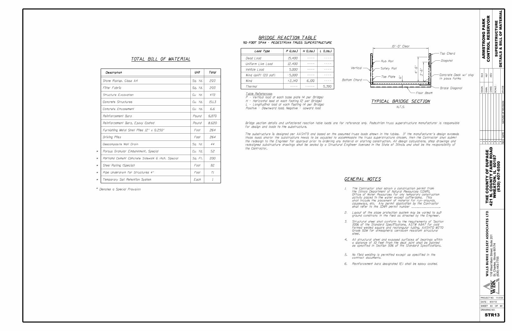
TYPICAL BRIDGE SECTION
Toe Plate
Safety Rail
Rub Rail
Vertical
Bottom Chord
Top Chord
Diagonal
in place forms
Concrete Deck w/ stay
Brace Diagonal
Floor Beam
N.T.S.
Load Type P (Lbs.) H (Lbs.) L (Lbs.)
Thermal
Wind
Wind Uplift (20 psf)
Vehicle Load
Uniform Live Load
Dead Load
BRIDGE REACTION TABLE
Positive - Downward load; Negative - Upward load
L - Longitudinal load at each footing (4 per Bridge)
H - Horizontal load at each footing (2 per Bridge)
P - Vertical load at each base plate (4 per Bridge)
Table References:
3’-
6"
Unit
TOTAL BILL OF MATERIAL
TotalDescription
*
* Denotes a Special Provision
*
*
*
*
GENERAL NOTES
4’-
6"
10’-0" Clear
50-FOOT SPAN - PEDESTRIAN TRUSS SUPERSTRUCTURE
-----
6,100
----
----
----
----
----
|2,140
-5,000
5,000
12,400
15,400
5,390
----
----
----
----
----
6.
5.
4.
3.
2.
1.
Reinforcement bars designated (E) shall be epoxy coated.
contract documents.
No field welding is permitted except as specified in the
as specified in Section 506 of the Standard Specifications.
a distance of 10 feet from the deck joint shall be painted
All structural steel and exposed surfaces of bearings within
steel.
Grade 50W for atmospheric corrosion resistant structural
formed welded square and rectangular tubing, AASHTO M270
1006 of the Standard Specifications, ASTM A847 for cold
Structural steel shall conform to the requirements of Section
ground conditions in the field as directed by the Engineer.
Layout of the slope protection system may be varied to suit
shall refer to the IDNR permit number _________________.
causeways, etc. Any permit application by the Contractor
shall include the placement of material for run-arounds,
activity placed in the water except cofferdams. This
Office of Water Resources for any temporary construction
the Illinois Department of Natural Resources (IDNR),
The Contractor shall obtain a construction permit from
the Contractor.
redesigned substructure drawings shall be sealed by a Structural Engineer licensed in the State of Illinois and shall be the responsibility of
the redesign to the Engineer for approval prior to ordering any material or starting construction. All design calculations, shop drawings and
those loads and/or the substructure needs to be adjusted to accommodate the truss superstructure chosen, then the Contractor shall submit
The substructure is designed per AASHTO and based on the assumed truss loads shown in the tables. If the manufacturer’s design exceeds
for design and loads to the substructure.
Bridge section details and unfactored reaction table loads are for reference only. Pedestrian truss superstructure manufacturer is responsible
Pipe Underdrain for Structures 4"
Granular Subgrade Replacement
Steel Railing (Special)
Portland Cement Concrete Sidewalk 6 inch, Special
Porous Granular Embankment, Special
Geocomposite Wall Drain
Driving Piles
Furnishing Metal Shell Piles 12" x 0.250"
Reinforcement Bars, Epoxy Coated
Reinforcement Bars
Concrete Encasement
Concrete Structures
Removal and Disposal of Unsuitable Material for Structures
Structure Excavation
Filter Fabric
Stone Riprap, Class A4
Foot
Cu. Yd.
Foot
Sq. Ft.
Cu. Yd.
Sq. Yd.
Foot
Foot
Pound
Pound
Cu. Yd.
Cu. Yd.
Cu. Yd.
Cu. Yd.
Sq. Yd.
Sq. Yd.
70
242
81
200
50
43
228
228
8,420
8,200
6.6
157.1
242
661
197
197
DATE :
DRAWING NO.
DS
GN.
CH
KD.
SC
ALE :
DW
N.
NA
TU
RE O
F R
EVISIO
NN
O.
DA
TE
(630) 443-7
755
St. C
harles, Illinois 6
0174
116 W
est
Main Street, S
uite 2
01
PROJECT NO.
DLS
HLF
AE
U
1
2
3
4
5
6
7
8
$FIL
ES$
TH
E C
OU
NT
Y O
F D
UP
AG
E
421 N.
CO
UN
TY F
AR
M R
OA
DW
HE
AT
ON, IL 60187
(630)
407-6
500
AR
MS
TR
ON
G P
AR
K
CO
NT
RO
L R
ES
ER
VOIR
STR2
SHEET 52 80
8/31/12
11-0125
OF
SU
PE
RS
TR
UC
TU
RE
DE
TAIL
S & B
ILL O
F M
AT
ERIA
L
FOOTING PLAN
1’-6"5’-3"5’-3"1’-6"
13’-6"
7’-
0"
11’-
3"
7’-
9"
1’-2" 1’-6"
7’-0"
1’-0"
u(E)
h(E)
13’-6"
v(E)
v1(E)
17-#5 v1(E) bars at 10" cts. (Front Face)
17-#5 v(E) bars at 10" cts. (Back Face)
(Each Face)
17-#5 n(E) bars at 10" cts.
17-#5 u(E) bars at 10" cts.
d(E)
(Each Face)
9-#
5 h(E)
bars at
12" cts.
2-#5 h(E) bars in Back Wall
t(E) w(E)
Bar No. Size Length Shape
BILL OF MATERIAL
BAR n(E)
BAR u(E)
BAR d(E)
2’-
4"
10"
2’-
7"
2’-4"
1’-0"
1’-0"4’-
4"
7"
5"
Top
&
Bott
om of Sla
b
8-#
5
w(E)
bars at
12" cts.
w(E)
v1(E)
v(E)
u1(E)
u(E)
t(E)
n(E)
h(E)
d(E)
32
34
34
34
34
64
68
40
34
#5
#5
#5
#5
#5
#5
#5
#5
#4
13’-2"
7’-5"
8’-5"
5’-6"
7’-6"
6’-8"
4’-11"
13’-2"
2’-0"
BAR u1(E)
u1(E)
PILE DATA
ELEVATION
2’-8"4’-4"
2’-
0"
~ Ftg.
n(E)
1’-3"4’-6"1’-3"
w(E)t(E)
17-#5 u1(E) bars at 10" cts.
typ.
2" Cl.
2"
3"
Cl.
Cl.
SECTION THRU ABUTMENT
6-#5 t(E) bars at 12" cts.
16-#5 t(E) bars at |12" cts.
Typ. between piles
Bott. of Slab
Top of Slab
1’-0"
2-#5 t(E) bars at 8" cts.
Ea. End, Bott. of Slab
17-#4 d(E) bars at |10" cts.
2’-
7"
Elev. 749.25
Elev. 738.00
Elev. 747.75
6"
8’-10"
Back Face
10’-0"
Const. Jt.
6x6 w4.0 x w4.0 wwf
P.C.C. Sidewalk 6" (Special)
Driving Piles.
Standard Specifications. Cost included in
according to Article 512.09 (c) of the
precored holes extending to elevation 733.8
Piles shall be driven through 18-inch diameter
No. Test Piles: 0
No. Production Piles: 6
Est. Length: 19’
Factored Resistance Available: 103 kips
Nominal Required Bearing: 187 kips
Type: Metal Shell - 12" dia. x 0.25" walls
Concrete Encasement, typ.3’-
0"
3’-
6"
3’-
6"
Sidewalk 6 inch, special
Portland Cement Concrete
Driving Piles
Piles 12" x 0.25"
Furnishing Metal Shell
Epoxy Coated
Reinforcement Bars,
Concrete Encasement
Concrete Structures
Structure Excavation
Sq. Ft.
Foot
Foot
Pound
Cu. Yd.
Cu. Yd.
Cu. Yd.
200
228
228
2,850
6.6
36.0
62
(Two Abutments)
DATE :
DRAWING NO.
DS
GN.
CH
KD.
SC
ALE :
DW
N.
NA
TU
RE O
F R
EVISIO
NN
O.
DA
TE
(630) 443-7
755
St. C
harles, Illinois 6
0174
116 W
est
Main Street, S
uite 2
01
PROJECT NO.
DLS
HLF
AE
U
1
2
3
4
5
6
7
8
$FIL
ES$
TH
E C
OU
NT
Y O
F D
UP
AG
E
421 N.
CO
UN
TY F
AR
M R
OA
DW
HE
AT
ON, IL 60187
(630)
407-6
500
AR
MS
TR
ON
G P
AR
K
CO
NT
RO
L R
ES
ER
VOIR
STR3
SHEET 53 80
8/31/12
11-0125
OF
AB
UT
ME
NT
S
ST
A. 301
+27.2
0
1’-0"
1’-0"
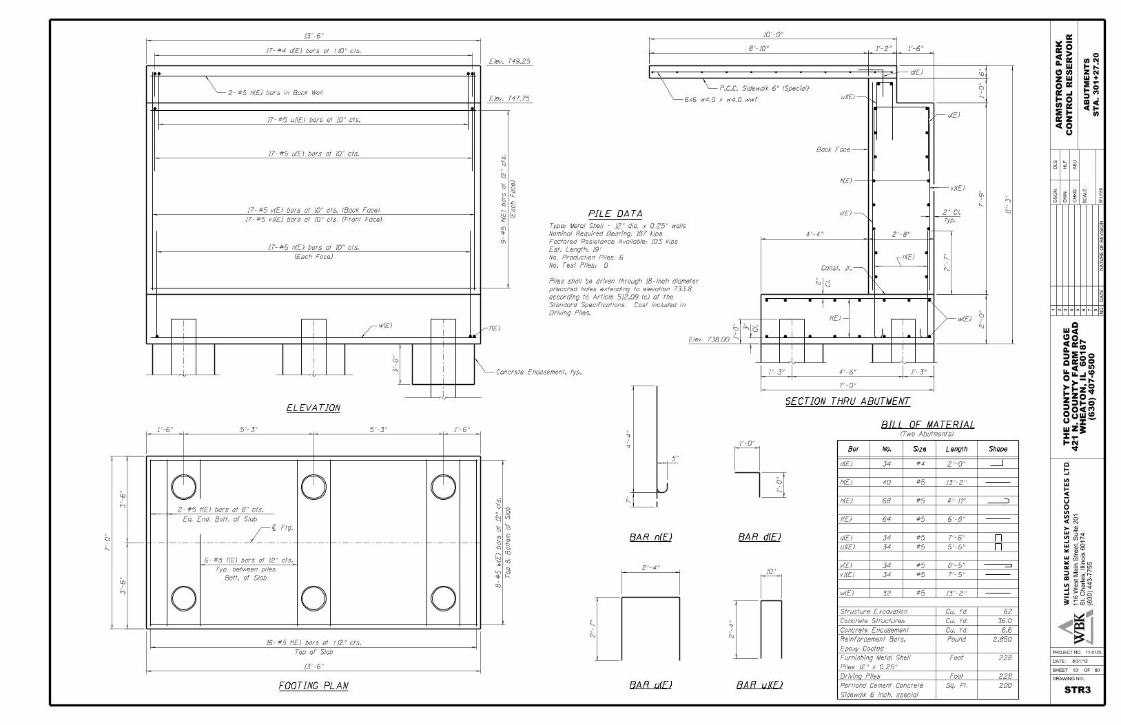
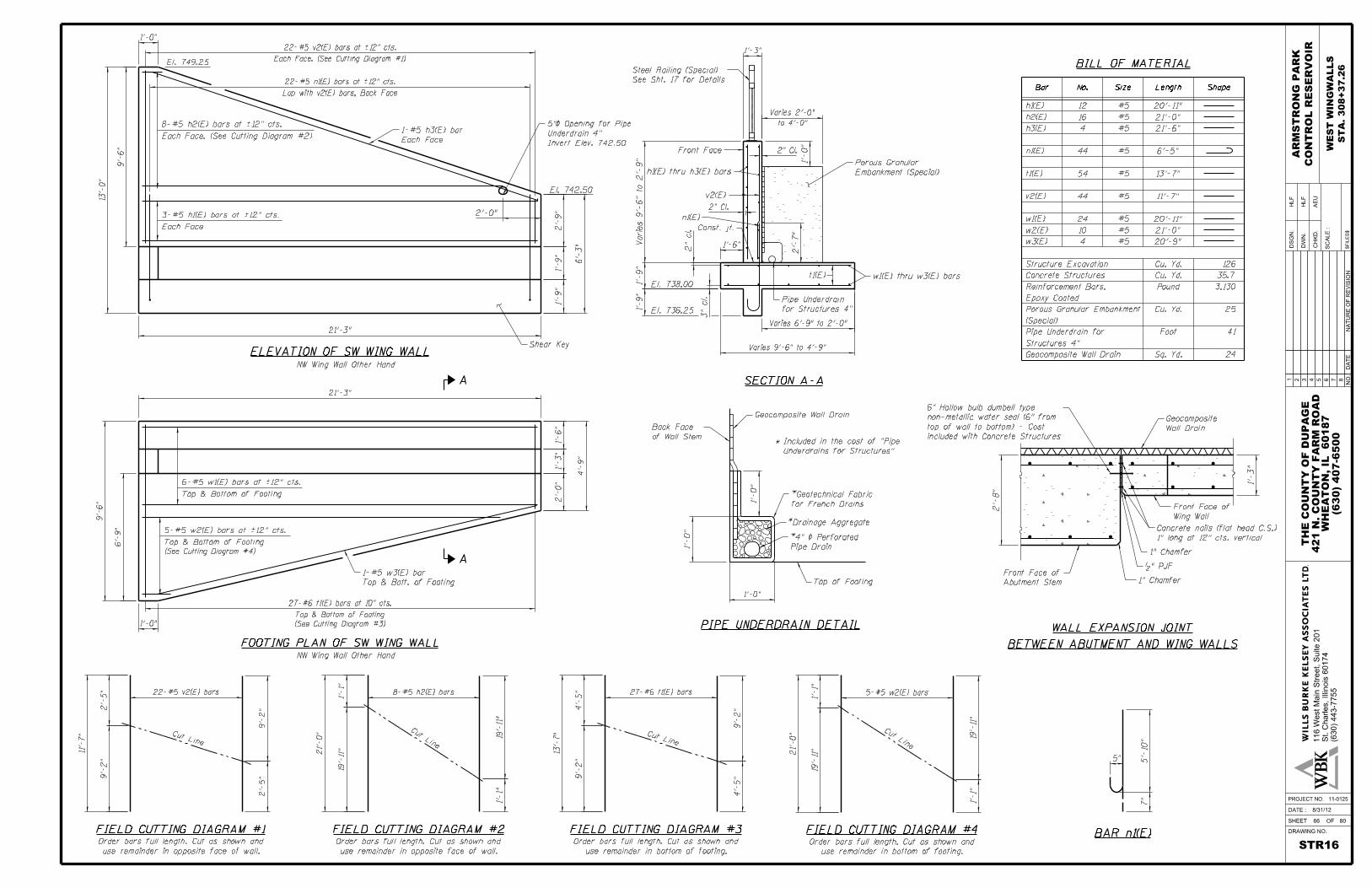
PIPE UNDERDRAIN DETAIL
Underdrains for Structures"
Included in the cost of "Pipe*
Geocomposite Wall Drain
for French Drains
*Geotechnical Fabric
Pipe Drain
*4" } Perforated
Top of Footing
*Drainage Aggregate
7"
5’-
10"
Bar No. Size Length Shape
BILL OF MATERIAL
ELEVATION OF NW WING WALL
FOOTING PLAN OF NW WING WALL
1’-0"
5"
11’-
7"
2’-
5"
2’-
5"
Cut Line
Wall Drain
Geocomposite
1" long at 12" cts. vertical
Concrete nails (flat head C.S.)
included with Concrete Structures
top of wall to bottom) - Cost
non-metallic water seal (6" from
6" Hollow bulb dumbell type
1" Chamfer
�" PJF
BETWEEN ABUTMENT AND WING WALLS
WALL EXPANSION JOINT
2" cl.
3" cl.
1’-0"
El. 738.00
2’-
7"
Front Face
for Structures 4"
Pipe Underdrain
Embankment (Special)
Porous Granular
Const. jt.
1’-3"
2" Cl.
2" Cl.
1’-6"
NE Wing Wall Other Hand
NE Wing Wall Other Hand
Varies 9’-6" to 4’-9"
Varies 6’-9" to 2’-0"
Varies 9’-
6" to 2’-
9"
1’-9"
13’-
0"
21’-3"
1’-9"
1’-9"
2’-
9"
Shear Key
1’-0"
9’-
2"
9’-
2"
21’-0"
1’-1"
1’-1"
Cut Line
use remainder in bottom of footing.
Order bars full length. Cut as shown and
13’-
7"
4’-
5"
4’-
5"
Cut Line
9’-
2"
9’-
2"
use remainder in opposite face of wall.
Order bars full length. Cut as shown and
Each Face
19’-
11"
19’-
11"
21’-3"
9’-
6"
1’-6"
1’-3"
2’-
0"
4’-
9"
use remainder in opposite face of wall.
Order bars full length. Cut as shown and
1’-0"
21’-0"
1’-1"
1’-1"
Cut Line
19’-
11"
19’-
11"
use remainder in bottom of footing.
Order bars full length. Cut as shown and
Top & Bottom of Footing
SECTION A-AA
A
4
10
24
44
54
44
4
16
12
#5
#5
#5
#5
#5
#5
#5
#5
#5
20’-7"
21’-0"
20’-11"
11’-7"
13’-7"
6’-5"
21’-6"
21’-0"
20’-11"
of Wall Stem
Back Face
v2(E)
n1(E)
h1(E) thru h3(E) bars
8-#5 h2(E) bars at |12" cts.
3-#5 h1(E) bars at |12" cts.
5-#5 w2(E) bars at |12" cts.
22-#5 v2(E) bars 8-#5 h2(E) bars 5-#5 w2(E) bars
Top & Bottom of Footing.
27-#6 t1(E) bars at 10" cts.
6-#5 w1(E) bars at |12" cts.
27-#6 t1(E) bars
w1(E) thru w3(E) bars
w3(E)
w2(E)
w1(E)
v2(E)
t1(E)
n1(E)
h3(E)
h2(E)
h1(E)
9’-
6"
6’-
3"
6’-
9"
Elev. 749.25
Elev. 742.50
FIELD CUTTING DIAGRAM #1 FIELD CUTTING DIAGRAM #2 FIELD CUTTING DIAGRAM #3 FIELD CUTTING DIAGRAM #4
1’-9"
El. 736.25
Each Face. (See Cutting Diagram #1)
22-#5 v2(E) bars at |12" cts.
Each Face. (See Cutting Diagram #2)
(See Cutting Diagram #4)
Top & Bottom of Footing.
(See Cutting Diagram #3)
MIN. BAR LAP
#5 bar = 2’-7"
Geocomposite Wall Drain
Structures 4"
Pipe Underdrain for
(Special)
Porous Granular Embankment
Epoxy Coated
Reinforcement Bars,
Concrete Structures
Structure Excavation
Sq. Yd.
Foot
Cu. Yd.
Pound
Cu. Yd.
Cu. Yd.
Abutment Stem
Front Face of
2’-
8"
1’-3"
Wing Wall
Front Face of
1" Chamfer
BAR n1(E)
Lap with v2(E) bars, Back Face
22-#5 n1(E) bars at |12" cts.
See Sht. 7 for Details
Steel Railing (Special)
t1(E)
Varies 2’-0"
to 4’-0"
Each Face
1-#5 h3(E) bar
Top & Bott. of Footing
1-#5 w3(E) bar
Invert Elev. 742.50
Underdrain 4"
5"} Opening for Pipe
2’-0"
24
41
25
3,130
35.7
168
DATE :
DRAWING NO.
DS
GN.
CH
KD.
SC
ALE :
DW
N.
NA
TU
RE O
F R
EVISIO
NN
O.
DA
TE
(630) 443-7
755
St. C
harles, Illinois 6
0174
116 W
est
Main Street, S
uite 2
01
PROJECT NO.
HLF
HLF
AE
U
1
2
3
4
5
6
7
8
$FIL
ES$
TH
E C
OU
NT
Y O
F D
UP
AG
E
421 N.
CO
UN
TY F
AR
M R
OA
DW
HE
AT
ON, IL 60187
(630)
407-6
500
AR
MS
TR
ON
G P
AR
K
CO
NT
RO
L R
ES
ER
VOIR
STR4
SHEET 54 80
8/31/12
11-0125
OF
NO
RT
H W
ING
WA
LS
ST
A. 301
+27.2
0
SAVED VIEWS, DON’T DELETE
7"
5’-
10"
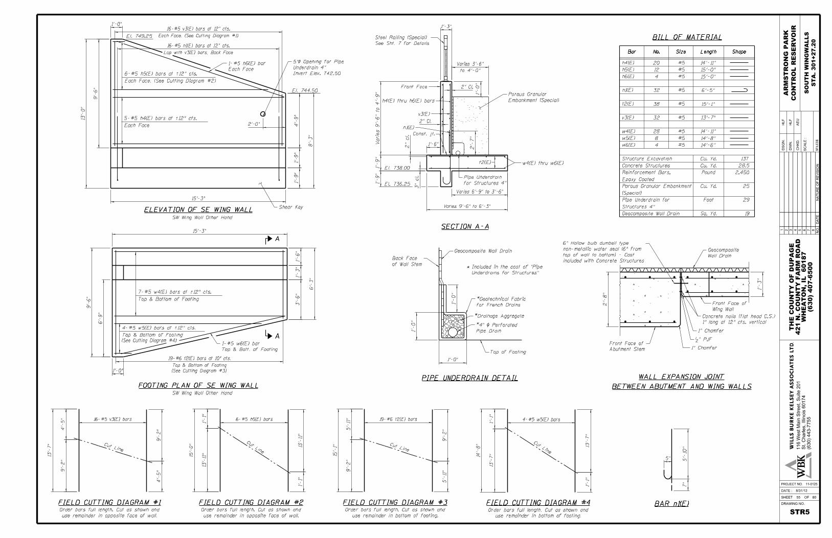
ELEVATION OF SE WING WALL
FOOTING PLAN OF SE WING WALL
5"
13’-
7"
4’-
5"
4’-
5"
Cut Line
SW Wing Wall Other Hand
SW Wing Wall Other Hand
Bar No. Size Length Shape
BILL OF MATERIAL
2" cl.
3" cl.
1’-0"
El. 738.00
2’-
7"
Front Face
for Structures 4"
Pipe Underdrain
Embankment (Special)
Porous Granular
Const. jt.
1’-3"
2" Cl.
2" Cl.
1’-6"
Varies 9’-6" to 6’-3"
Varies 6’-9" to 3’-6"
Varies 9’-
6" to 4’-
9"
1’-9"
SECTION A-A
15’-
0"
1’-1"
1’-1"
Cut Line
use remainder in bottom of footing.
Order bars full length. Cut as shown and
15’-
1"
Cut Line
9’-
2"
9’-
2"
13’-
11"
13’-
11"
use remainder in opposite face of wall.
Order bars full length. Cut as shown and
14’-
8"
1’-1"
1’-1"
Cut Line
13’-
7"
13’-
7"
use remainder in bottom of footing.
Order bars full length. Cut as shown and
1’-0"
13’-
0"
4’-
9"
1’-9"
1’-9"
Shear Key
15’-3"
Each Face
9’-
2"
9’-
2"
use remainder in opposite face of wall.
Order bars full length. Cut as shown and
15’-3"
9’-
6"
1’-0"
3’-
6"
1’-3"
1’-6"
Top & Bottom of Footing
Top & Bottom of Footing A
A
6’-
3"
5’-
11"
5’-
11"
v3(E)
4
8
28
32
38
32
4
12
20
#5
#5
#5
#5
#5
#5
#5
#5
#5
h4(E) thru h6(E) bars
1’-0"
1’-0"
PIPE UNDERDRAIN DETAIL
Underdrains for Structures"
Included in the cost of "Pipe*
Geocomposite Wall Drain
for French Drains
*Geotechnical Fabric
Pipe Drain
*4" } Perforated
Top of Footing
*Drainage Aggregate
1’-0"
of Wall Stem
Back Face
w6(E)
w5(E)
w4(E)
v3(E)
t2(E)
n1(E)
h6(E)
h5(E)
h4(E)
n1(E)
6-#5 h5(E) bars at |12" cts.
5-#5 h4(E) bars at |12" cts.
7-#5 w4(E) bars at |12" cts.
4-#5 w5(E) bars at |12" cts.
16-#5 v3(E) bars 6-#5 h5(E) bars 19-#6 t2(E) bars 4-#5 w5(E) bars
Top & Bottom of Footing
19-#6 t2(E) bars at 10" cts.
FIELD CUTTING DIAGRAM #1 FIELD CUTTING DIAGRAM #2 FIELD CUTTING DIAGRAM #3 FIELD CUTTING DIAGRAM #4 BAR n1(E)
9’-
6"
El. 749.25
El. 744.50
8’-
3"
Each Face. (See Cutting Diagram #1)
16-#5 v3(E) bars at 12" cts.
Lap with v3(E) bars, Back Face
16-#5 n1(E) bars at 12" cts.
Each Face
1-#5 h6(E) bar
Each Face. (See Cutting Diagram #2)
6’-
9"
(See Cutting Diagram #4)
Top & Bott. of Footing
1-#5 w6(E) bar
(See Cutting Diagram #3)
1’-9"
El. 736.25
Geocomposite Wall Drain
Structures 4"
Pipe Underdrain for
(Special)
Porous Granular Embankment
Epoxy Coated
Reinforcement Bars,
Concrete Structures
Structure Excavation
Sq. Yd.
Foot
Cu. Yd.
Pound
Cu. Yd.
Cu. Yd.
Wall Drain
Geocomposite
1" long at 12" cts. vertical
Concrete nails (flat head C.S.)
included with Concrete Structures
top of wall to bottom) - Cost
non-metallic water seal (6" from
6" Hollow bulb dumbell type
1" Chamfer
�" PJF
BETWEEN ABUTMENT AND WING WALLS
WALL EXPANSION JOINT
Abutment Stem
Front Face of
2’-
8"
1’-3"
Wing Wall
Front Face of
1" Chamfer
See Sht. 7 for Details
Steel Railing (Special)
t2(E) w4(E) thru w6(E)
Varies 3’-6"
to 4’-0"
14’-6"
14’-8"
14’-11"
13’-7"
15’-1"
6’-5"
15’-0"
15’-0"
14’-11"
Invert Elev. 742.50
Underdrain 4"
5"} Opening for Pipe
2’-0"
19
29
25
2,450
28.5
137
DATE :
DRAWING NO.
DS
GN.
CH
KD.
SC
ALE :
DW
N.
NA
TU
RE O
F R
EVISIO
NN
O.
DA
TE
(630) 443-7
755
St. C
harles, Illinois 6
0174
116 W
est
Main Street, S
uite 2
01
PROJECT NO.
HLF
HLF
AE
U
1
2
3
4
5
6
7
8
$FIL
ES$
TH
E C
OU
NT
Y O
F D
UP
AG
E
421 N.
CO
UN
TY F
AR
M R
OA
DW
HE
AT
ON, IL 60187
(630)
407-6
500
AR
MS
TR
ON
G P
AR
K
CO
NT
RO
L R
ES
ER
VOIR
STR5
SHEET 55 80
8/31/12
11-0125
OF
SO
UT
H W
ING
WA
LL
S
ST
A. 301
+27.2
0
SAVED VIEWS, DON’T DELETE
N
section and backfilling with coarse aggregate
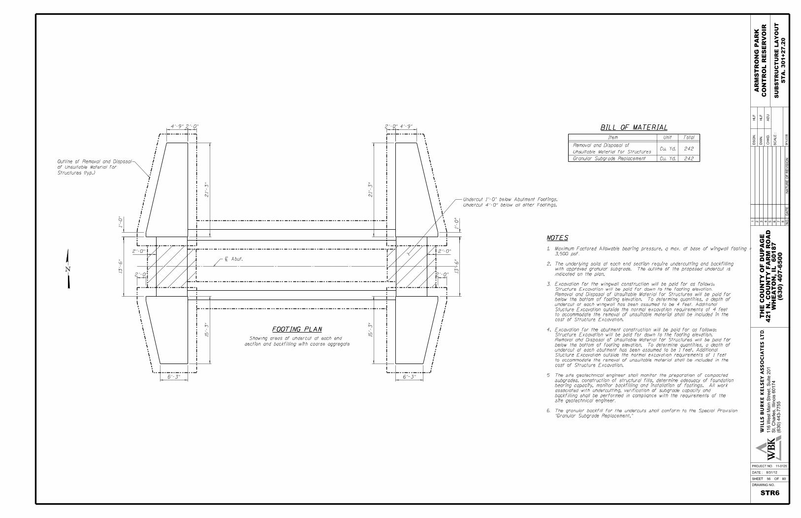
Showing areas of undercut at each end
Item Unit Total
BILL OF MATERIAL
Cu. Yd.
Cu. Yd.
NOTES
Granular Subgrade Replacement
Unsuitable Material for Structures
Removal and Disposal of
~ Abut.
6.
5.
4.
3.
2.
1.
242
242
15’-
3"
21’-3"
4’-9" 2’-0"
1’-0"
2’-0"
2’-0"
6’-3"
Structures (typ.)
of Unsuitable Material for
Outline of Removal and Disposal
13’-
6"
15’-
3"
21’-3"
4’-9"2’-0"
1’-0"
2’-0"
2’-0"
6’-3"
13’-
6"
FOOTING PLAN
Undercut 4’-0" below all other Footings.
Undercut 1’-0" below Abutment Footings.
"Granular Subgrade Replacement."
The granular backfill for the undercuts shall conform to the Special Provision
site geotechnical engineer.
backfilling shall be performed in compliance with the requirements of the
associated with undercutting, verification of subgrade capacity and
bearing capacity, monitor backfilling and installation of footings. All work
subgrades, construction of structural fills, determine adequacy of foundation
The site geotechnical engineer shall monitor the preparation of compacted
cost of Structure Excavation.
to accommodate the removal of unsuitable material shall be included in the
Stucture Excavation outside the normal excavation requirements of 1 feet
undercut at each abutment has been assumed to be 1 feet. Additional
below the bottom of footing elevation. To determine quantities, a depth of
Removal and Disposal of Unsuitable Material for Structures will be paid for
Structure Excavation will be paid for down to the footing elevation.
Excavation for the abutment construction will be paid for as follows:
cost of Structure Excavation.
to accommodate the removal of unsuitable material shall be included in the
Stucture Excavation outside the normal excavation requirements of 4 feet
undercut at each wingwall has been assumed to be 4 feet. Additional
below the bottom of footing elevation. To determine quantities, a depth of
Removal and Disposal of Unsuitable Material for Structures will be paid for
Structure Excavation will be paid for down to the footing elevation.
Excavation for the wingwall construction will be paid for as follows:
indicated on the plan.
with approved granular subgrade. The outline of the proposed undercut is
The underlying soils at each end section require undercutting and backfilling
3,500 psf.
Maximum Factored Allowable bearing pressure, q max, at base of wingwall footing =
DATE :
DRAWING NO.
DS
GN.
CH
KD.
SC
ALE :
DW
N.
NA
TU
RE O
F R
EVISIO
NN
O.
DA
TE
(630) 443-7
755
St. C
harles, Illinois 6
0174
116 W
est
Main Street, S
uite 2
01
PROJECT NO.
HLF
HLF
AE
U
1
2
3
4
5
6
7
8
$FIL
ES$
TH
E C
OU
NT
Y O
F D
UP
AG
E
421 N.
CO
UN
TY F
AR
M R
OA
DW
HE
AT
ON, IL 60187
(630)
407-6
500
AR
MS
TR
ON
G P
AR
K
CO
NT
RO
L R
ES
ER
VOIR
STR6
SHEET 56 80
8/31/12
11-0125
OF
SU
BS
TR
UC
TU
RE L
AY
OU
T
ST
A. 301
+27.2
0

�
�
FootSteel Railing (Special)
HSS 3 x 3 x �
tapping screws
~ �" Self-
HSS 2� x 2� x � x 9" lg.HSS 3 x 3 x �
P �"L
1" x 1�" Slotted hole
�
HSS 3 x 3 x �
HSS 3 x 3 x �
Detail B
Detail A
Detail D
retaining wall
Top of
ANCHOR BOLT DETAILS
be according to the manufacturer’s specifications.
to Article 509.06 of the Standard Specifications. Embedment shall
has the option of drilling and setting �’’ } anchor rods according
In lieu of the cast-in-place anchor device shown, the Contractor
� �
L
NOTES
3.
2.
1.
Reinforcement shall be spaced to to miss anchor rods.
two coats of a black powder-coated finish.
shall be painted using one coat of zinc-rich primer and
All post, railing, splices, anchor devices, and bent plates
Railing (Special).
All work shall conform to the special provision Steel
~ Post
HSS 3 x 3 x �
�" Fabric pad
~ Post
HSS 3 x 3 x�
�" } mach. bolts
XXS Pipe - Tap for
�" } (nominal i.d.)
�" x 1�" x 5�" Bar
P �" x 6" x 8�"
bolts w/washer (Stainless steel)
�" } x 2" hex hd. machine
Top of retaining wall
RAIL SPLICE
BASE PLATE
DETAIL D
SECTION
DETAIL A DETAIL B
DETAIL CELEVATION
STEEL RAILING (SPECIAL)
face of wall
Ground line at back
3" min.
BILL OF MATERIAL
Item Unit Quantity
P �" x 3" x 3"L
HSS 3 x 3 x � HSS 3 x 3 x �
HSS 3 x 3 x �
picket
�" x �" Steel
HSS 3 x 3 x �
R 2�"typ.
5�"
3"
North Wingwalls
6’-8" Post Spacing
|4"
HSS 3 x 3 x �
1’-6"
6"
1"2"2"1"
8�"
1�"
2�
"2�
"1�
"
9"
1"2"1�"1�"2"1"
3�
"3�
"
�" rail splice
3�"3�"
3"
6"
2�"2�"
4"
2"2"
3’-
6"
7�"
Detail C
typ.
1’-0�"
3’-
6"
(Special)
Steel Railing
Top of retaining wall
1’-10�"
5�"
5�"�" �"
South Wingwalls
6’-11" Post Spacing
North & South Wingwalls
6 Pickets
80
DATE :
DRAWING NO.
DS
GN.
CH
KD.
SC
ALE :
DW
N.
NA
TU
RE O
F R
EVISIO
NN
O.
DA
TE
(630) 443-7
755
St. C
harles, Illinois 6
0174
116 W
est
Main Street, S
uite 2
01
PROJECT NO.
HLF
HLF
DLS
1
2
3
4
5
6
7
8
$FIL
ES$
TH
E C
OU
NT
Y O
F D
UP
AG
E
421 N.
CO
UN
TY F
AR
M R
OA
DW
HE
AT
ON, IL 60187
(630)
407-6
500
AR
MS
TR
ON
G P
AR
K
CO
NT
RO
L R
ES
ER
VOIR
STR7
SHEET 57 80
8/31/12
11-0125
OF
ST
EE
L R
AILIN
G (
SP
ECIA
L)
ST
A. 301
+27.2
0

47’-3"
47’-3"
7’-
0"
7’-
6"
SECTION A-A
A
A
6’-1�"
6"
6"
6" Elev. 745.00
Elev. 746.00
7’-
6"
7’-
0"
47’-3"
v4
a2
a1a
v5
47’-3"
47’-3"
2’-
8"
3’-
6"
Const. Jt.
13’-
6"
a5
1’-0"
Const. Jt.
Elev. 745.50
Bend in field
nosing (typ.)Rounded
Elev. 738.00 Elev. 738.00
typ.
3" cl.
typ.
3" cl.
T&
B ty
p.
3" cl.
3’-7�"1’-0"1’-0"1’-3" 6"
typ.
3" cl.
typ.
3" cl. a3
a4
n2
t4
t5
1’-0"
b
b
b
Top & bottom of footing
48-#5 t4 bars at 12" cts.
MIN. BAR LAP
NORTH FOOTING
PLAN
SOUTH FOOTING
PLAN
SECTION THRU WEIR SLAB
See note
ELEVATION - NORTH WALL
ELEVATION - SOUTH WALL
25’-0"22’-3"
23-#5 n2 bars at 12" cts. - Each face 26-#5 n2 bars at 12" cts. - Each face
Each face
31-#5 v4 bars at 12" cts.
Each face
27-#5 v4 bars at 12" cts.
Each face
27-#5 v5 bars at 12" cts.
Each face
31-#5 v5 bars at 12" cts.
25’-0"22’-3"
23-#5 n2 bars at 12" cts. - Each face 26-#5 n2 bars at 12" cts. - Each face
PLAN - TOP OF WEIR
h11h11
w10 w10
h10
Each face
5-#5 h11 bars at 15" cts.
Each face
5-#5 h11 bars at 15" cts.
n2
Each face
4-#5 h11 bars at 15" cts.
Each face
4-#5 h11 bars at 15" cts.
58-#5 a2 bars at 10" cts. - Bottom of slab
58-#5 a5 bars at 10" cts. - Top of slab
cts. - T
&B of sla
b
7x2-#
5 bars at
15"
cts. - T
&
B of sla
b
4x2-#
5 b bars at
15"
58-#5 a1 bars at 10" cts. - Top of slab
58-#5 a4 bars at 10" cts. - Top of slab
1x2-#5 b bars - T & B of steps
1x2-#5 b bar in Top of curb
Cut bar to fit
Const. jt.
Const. jt.
58-#5 a bars at 10" cts. - Bottom of slab
58-#5 a3 bars at 10" cts. - Top of slab
58-#5 h10 bars at 10" cts. - Top of step
58-#5 h10 bars at 10" cts. - Top of step
cost of Concrete Structures.
paid for separately, but shall be included in the
CA 18. The porous granular material shall not be
porous granular material shall be CA 7, CA 11 or
material shall be placed below the weir slab. The
Note: A 1-foot layer of compacted porous granular
All other #5 bars = 1’-9"
#5 h11 bars = 2’-5"
7 lines of bars with 2 lengths per line.
Bars indicated "7x2-#5 bars" indicates
16’-0"
10"1’-0"1’-8" 10"1’-0"10"
Bottom of footing
48-#5 t5 bars at 12" cts.
Top & bottom of footing
4x2-#5 w10 bars at 12" cts.
Bottom of footing
3x2-#5 w10 bars at 12" cts.
1’-4"
4’-
2"
1’-6"1’-0"
5’-
2"
1’-4"
typ.
1’-9"
2’-8"9’-10"3’-6"
1’-0"
N
Looking east
DATE :
DRAWING NO.
DS
GN.
CH
KD.
SC
ALE :
DW
N.
NA
TU
RE O
F R
EVISIO
NN
O.
DA
TE
(630) 443-7
755
St. C
harles, Illinois 6
0174
116 W
est
Main Street, S
uite 2
01
PROJECT NO.
DLS
HLF
AE
U
1
2
3
4
5
6
7
8
$FIL
ES$
TH
E C
OU
NT
Y O
F D
UP
AG
E
421 N.
CO
UN
TY F
AR
M R
OA
DW
HE
AT
ON, IL 60187
(630)
407-6
500
AR
MS
TR
ON
G P
AR
K
CO
NT
RO
L R
ES
ER
VOIR
STR8
SHEET 58 80
8/31/12
11-0125
OF
WEIR D
ET
AIL
S I
ST
A. 301
+27.2
0

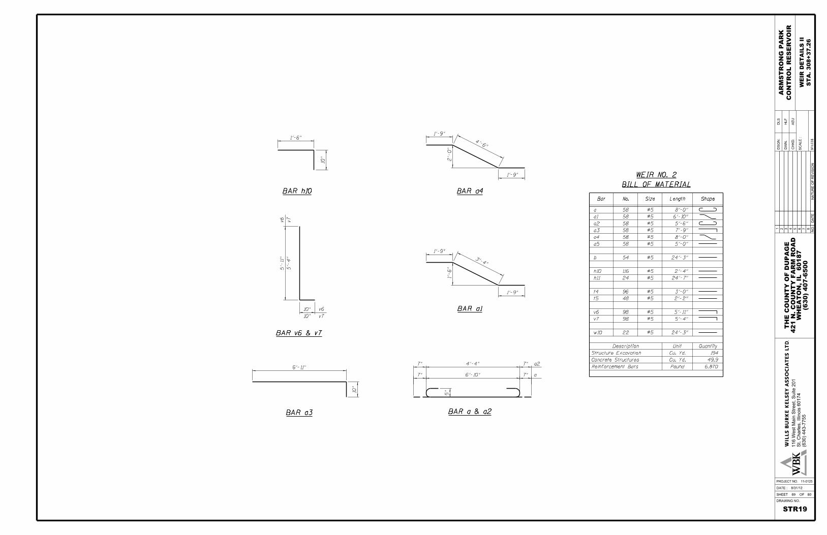
Bar No. Size Length Shape
BILL OF MATERIAL
Reinforcement Bars
Concrete Structures
Structure Excavation
Pound
Cu. Yd.
Cu. Yd.
8,200
56.9
2947"6’-10"7"
7"4’-4"7"
1’-6"
3’-4"
1’-9"
1’-9"
BAR a1
2’-
0"
4’-6"
1’-9"
1’-9"
BAR a4
10"
6’-11"
BAR n2
10"
3’-
0"
1’-6"
10"
WEIR NO. 1
w10
v5
v4
t5
t4
n2
h11
h10
b
a5
a4
a3
a2
a1
a
#5
#5
#5
#5
#5
#5
#5
#5
#5
#5
#5
#5
#5
#5
#5
BAR h10
BAR a & a2
a2
a
BAR a3
24’-3"
5’-6"
6’-0"
2’-2"
3’-0"
3’-10"
24’-7"
2’-4"
24’-3"
5’-0"
8’-0"
7’-9"
5’-6"
6’-10"
8’-0"
Description Unit Quantity
5"
22
116
116
48
96
196
36
116
52
58
58
58
58
58
58
DATE :
DRAWING NO.
DS
GN.
CH
KD.
SC
ALE :
DW
N.
NA
TU
RE O
F R
EVISIO
NN
O.
DA
TE
(630) 443-7
755
St. C
harles, Illinois 6
0174
116 W
est
Main Street, S
uite 2
01
PROJECT NO.
DLS
HLF
AE
U
1
2
3
4
5
6
7
8
$FIL
ES$
TH
E C
OU
NT
Y O
F D
UP
AG
E
421 N.
CO
UN
TY F
AR
M R
OA
DW
HE
AT
ON, IL 60187
(630)
407-6
500
AR
MS
TR
ON
G P
AR
K
CO
NT
RO
L R
ES
ER
VOIR
STR9
SHEET 59 80
8/31/12
11-0125
OF
WEIR D
ET
AIL
S II
ST
A. 301
+27.2
0
typ.
3’’ Pitch
Spiral
#4 bar
cl.2
’’
B B
7’-6" long
6-#5 bars
SECTION B-B
6’’ Horizontal bend, typ.
7’-
0’’
Metal shell piles
Metal shell pile
See Detail A
DETAIL A
A A
SECTION A-A
ELEVATION
Metal shell pile
min.
�’’
min.
�’’
�’’ min.
Fill bar �’’ x
welding
(within 0.01’’) before
Cut square for tight fit
PP12
PP14
22.60 0.0274
PP12
PP14
3
31.37 0.0267
36.71 0.0368
45.61 0.0361
�’’
�’’ End plate
min.
�’’
METAL SHELL PILE TABLE
|10’’
ELEVATION
Dia
meter
t
WELDED COMMERCIAL SPLICE
t
thickness
Wall
0.179’’
0.250’’
0.250’’
0.312’’
(yd. /ft.)
volume
Inside
pile
Metal shell t
END PLATE ATTACHMENT
pile
Metal shell
METAL SHELL PILE SHOE ATTACHMENT COMPLETE PENETRATION WELD SPLICE
pile
Metal shell
t
t
pile
Metal Shell
METAL SHELL REINFORCEMENT AT ABUTMENTS
F-MS
s
Approx.
�’’
(Lbs./ft.)
foot
per
Weight
abutment
Bottom of
splicer before welding.
Pile segments shall be driven to solid contact with
2 bars with a �’’ max. gap between them.
The �’’ x �’’ min. fill bar may be constructed of
Notes:
field weld
Shop or
ASTM A 252 Grade 3.
The metal shell piles shall be according to
Note:
�See Detail A, typ.
CONCRETE ENCASEMENT AT PIERS
cl.
3’’
pier wall
required to fit into the
58#/100 sq. ft. Bend as
W4.0 x W4.0 weighing
Welded wire fabric 6 x 6-diameter
and outside
Designation
2’-6’’
min.
7�’’
soil conditions permit.
Forms for encasement may be omitted when
Note:
60°
(See Note A)
weld.
shall be secured to the pile with a circumferential
leads to assure proper alignment and fitting and
metal shell pile. The pile shoe shall have tapered
full bearing over the full circumference of the
AASHTO M 103 Grade 65-35 and shall provide
according to either ASTM A 148 Grade 90-60 or
The pile shoes shall be cast in one piece steel
of a single piece conical pile point as shown.
shall furnish metal shell pile shoes consisting
When called for on the plans, the Contractor
Note A:
backing ring
or commercial
Field fabricated
*
vertically rejoin with partial joint penetration weld.
by removing segment to allow reducing circumference and
Field fabricated backing ring may be made from pile shell*
s field weld
Shop or
s = t - �’’
60°
s = t - �’’
60° field weld
Shop or
60°
encase
ment
Concrete
1-27-12
pile cap
Bottom of
DATE :
DRAWING NO.
DS
GN.
CH
KD.
SC
ALE :
DW
N.
NA
TU
RE O
F R
EVISIO
NN
O.
DA
TE
(630) 443-7
755
St. C
harles, Illinois 6
0174
116 W
est
Main Street, S
uite 2
01
PROJECT NO.
HLF
HLF
AE
U
1
2
3
4
5
6
7
8
$FIL
ES$
TH
E C
OU
NT
Y O
F D
UP
AG
E
421 N.
CO
UN
TY F
AR
M R
OA
DW
HE
AT
ON, IL 60187
(630)
407-6
500
AR
MS
TR
ON
G P
AR
K
CO
NT
RO
L R
ES
ER
VOIR
STR10
SHEET 60 80
8/31/12
11-0125
OF
ME
TA
L S
HE
LL PIL
E
DE
TAIL
S

DATE :
DRAWING NO.
DS
GN.
CH
KD.
SC
ALE :
DW
N.
NA
TU
RE O
F R
EVISIO
NN
O.
DA
TE
(630) 443-7
755
St. C
harles, Illinois 6
0174
116 W
est
Main Street, S
uite 2
01
PROJECT NO.
HLF
HLF
AE
U
1
2
3
4
5
6
7
8
$FIL
ES$
TH
E C
OU
NT
Y O
F D
UP
AG
E
421 N.
CO
UN
TY F
AR
M R
OA
DW
HE
AT
ON, IL 60187
(630)
407-6
500
AR
MS
TR
ON
G P
AR
K
CO
NT
RO
L R
ES
ER
VOIR
STR11
SHEET 61 80
8/31/12
11-0125
OF
SOIL B
ORIN
G L
OG
DESIGN SPECIFICATIONS
Pedestrian Bridges, December 2009.
LRFD Guide Specifications for the Design of
6th Edition.
2012 AASHTO LRFD Bridge Design Specifications,
Elev. 744.00
Elev. 742.00
Elev. 749.25
Elev. 743.00
Elev. 744.00 Elev. 743.50
PLAN
SECTION A-A
A
A
~ Path
~ Path
N
Sta. 308+10.97
Bk. S. Abut.
52’-7"
50’-0"
15’-9"13’-6"21’-3"
Sta. 308+63.55
Bk. N. Abut.
52’-7" Back to Back Abutments
13’-
6"
21’-3"
15’-
9"
Bedding
Filter fabric
3’-0’’
2’-
8’’
4’-0’’
B
B
Class A4
Stone Riprap,
PROFILE GRADE
Struct.
Prop.
Along ~ Path
+0.00%Elev. 749.25
SECTION B-B
Flo
w
Flow
Boring #W314
50’-0" Span
Sta. 308+37.26
~ Structure
2’-
0"
8’-
0"
2’-
0"
13’-
6"
Sealand Expiration Date
Signature, Title, Date,
SEISMIC DATA
Soil Site Class = D
Design Spectral Acceleration at 0.2 sec. (S ) = 14.3
Design Spectral Acceleration at 1.0 sec. (S ) = 8.5
Seismic Performance Zone (SPZ) = 1
D1
DS
LOADING H5 & PEDESTRIAN:
Vehicle: H-5 Truck
Pedestrian: 90 psf (No reduction)
INDEX OF SHEETS:
Additional Riprap Details
See Civil Sheets for
Design Specifications".
requirements of the current "AASHTO LRFD Bridge
one for the style of structure and complies with
shown on the plans. The design is an economical
design is structurally adequate for the design loading
information and belief, the bridge and structure
I certify that to the best of my knowledge
Truss Superstructure
Bowstring Pedestrian
Concrete Weir
Reinforced
Elev. 738.00Elev. 738.00
Elev. 738.00Elev. 738.00
12"} Metal Shell Piles
FIELD UNITS
DESIGN STRESSES
fy = 50,000 psi (M270 Grade 50W)
fy = 60,000 psi (Reinforcement)
f’c = 3,500 psi
P.C.C. Sidewalk 6", Special
Provision.
construction. See Special
System as required for
Temporary Soil Retention
ELEVATION
16"
6"
STR21 Soil Boring Log
STR20 Metal Shell Pile Details
STR19 Weir Details II
STR18 Weir Details I
STR17 Steel Railing (Special)
STR16 West Wingwalls
STR15 East Wingwalls
STR14 Abutments
and Bill of Material
STR13 Superstructure Details
STR12 General Plan & Elevation
DATE :
DRAWING NO.
DS
GN.
CH
KD.
SC
ALE :
DW
N.
NA
TU
RE O
F R
EVISIO
NN
O.
DA
TE
(630) 443-7
755
St. C
harles, Illinois 6
0174
116 W
est
Main Street, S
uite 2
01
PROJECT NO.
DLS
HLF
AE
U
1
2
3
4
5
6
7
8
$FIL
ES$
TH
E C
OU
NT
Y O
F D
UP
AG
E
421 N.
CO
UN
TY F
AR
M R
OA
DW
HE
AT
ON, IL 60187
(630)
407-6
500
AR
MS
TR
ON
G P
AR
K
CO
NT
RO
L R
ES
ER
VOIR
STR12
SHEET 62 80
8/31/12
11-0125
OF
GE
NE
RA
L P
LA
N & E
LE
VA
TIO
N
ST
A. 308
+37.2
6
TYPICAL BRIDGE SECTION
Toe Plate
Safety Rail
Rub Rail
Vertical
Bottom Chord
Top Chord
Diagonal
in place forms
Concrete Deck w/ stay
Brace Diagonal
Floor Beam
N.T.S.
Load Type P (Lbs.) H (Lbs.) L (Lbs.)
Thermal
Wind
Wind Uplift (20 psf)
Vehicle Load
Uniform Live Load
Dead Load
BRIDGE REACTION TABLE
Positive - Downward load; Negative - Upward load
L - Longitudinal load at each footing (4 per Bridge)
H - Horizontal load at each footing (2 per Bridge)
P - Vertical load at each base plate (4 per Bridge)
Table References:
3’-
6"
Unit
TOTAL BILL OF MATERIAL
TotalDescription
*
* Denotes a Special Provision
*
*
*
* GENERAL NOTES
4’-
6"
10’-0" Clear
50-FOOT SPAN - PEDESTRIAN TRUSS SUPERSTRUCTURE
-----
6,100
----
----
----
----
----
|2,140
-5,000
5,000
12,400
15,400
5,390
----
----
----
----
----
6.
5.
4.
3.
2.
1.
Reinforcement bars designated (E) shall be epoxy coated.
contract documents.
No field welding is permitted except as specified in the
as specified in Section 506 of the Standard Specifications.
a distance of 10 feet from the deck joint shall be painted
All structural steel and exposed surfaces of bearings within
steel.
Grade 50W for atmospheric corrosion resistant structural
formed welded square and rectangular tubing, AASHTO M270
1006 of the Standard Specifications, ASTM A847 for cold
Structural steel shall conform to the requirements of Section
ground conditions in the field as directed by the Engineer.
Layout of the slope protection system may be varied to suit
shall refer to the IDNR permit number _________________.
causeways, etc. Any permit application by the Contractor
shall include the placement of material for run-arounds,
activity placed in the water except cofferdams. This
Office of Water Resources for any temporary construction
the Illinois Department of Natural Resources (IDNR),
The Contractor shall obtain a construction permit from
the Contractor.
redesigned substructure drawings shall be sealed by a Structural Engineer licensed in the State of Illinois and shall be the responsibility of
the redesign to the Engineer for approval prior to ordering any material or starting construction. All design calculations, shop drawings and
those loads and/or the substructure needs to be adjusted to accommodate the truss superstructure chosen, then the Contractor shall submit
The substructure is designed per AASHTO and based on the assumed truss loads shown in the tables. If the manufacturer’s design exceeds
for design and loads to the substructure.
Bridge section details and unfactored reaction table loads are for reference only. Pedestrian truss superstructure manufacturer is responsible
1
71
82
200
52
44
264
264
8,620
6,870
6.6
151.3
472
203
203
Temporary Soil Retention System
Pipe Underdrain for Structures 4"
Steel Railing (Special)
Portland Cement Concrete Sidewalk 6 inch, Special
Porous Granular Embankment, Special
Geocomposite Wall Drain
Driving Piles
Furnishing Metal Shell Piles 12" x 0.250"
Reinforcement Bars, Epoxy Coated
Reinforcement Bars
Concrete Encasement
Concrete Structures
Structure Excavation
Filter Fabric
Stone Riprap, Class A4
Each
Foot
Foot
Sq. Ft.
Cu. Yd.
Sq. Yd.
Foot
Foot
Pound
Pound
Cu. Yd.
Cu. Yd.
Cu. Yd.
Sq. Yd.
Sq. Yd.
6"
DATE :
DRAWING NO.
DS
GN.
CH
KD.
SC
ALE :
DW
N.
NA
TU
RE O
F R
EVISIO
NN
O.
DA
TE
(630) 443-7
755
St. C
harles, Illinois 6
0174
116 W
est
Main Street, S
uite 2
01
PROJECT NO.
DLS
HLF
AE
U
1
2
3
4
5
6
7
8
$FIL
ES$
TH
E C
OU
NT
Y O
F D
UP
AG
E
421 N.
CO
UN
TY F
AR
M R
OA
DW
HE
AT
ON, IL 60187
(630)
407-6
500
AR
MS
TR
ON
G P
AR
K
CO
NT
RO
L R
ES
ER
VOIR
STR13
SHEET 63 80
8/31/12
11-0125
OF
SU
PE
RS
TR
UC
TU
RE
DE
TAIL
S & B
ILL O
F M
AT
ERIA
L

FOOTING PLAN
1’-6"5’-3"5’-3"1’-6"
13’-6"
7’-
0"
11’-
3"
7’-
9"
1’-2" 1’-6"
7’-0"
1’-0"
u(E)
h(E)
13’-6"
v(E)
v1(E)
17-#5 v1(E) bars at 10" cts. (Front Face)
17-#5 v(E) bars at 10" cts. (Back Face)
(Each Face)
17-#5 n(E) bars at 10" cts.
17-#5 u(E) bars at 10" cts.
d(E)
(Each Face)
9-#
5 h(E)
bars at
12" cts.
2-#5 h(E) bars in Back Wall
t(E) w(E)
Bar No. Size Length Shape
BILL OF MATERIAL
BAR n(E)
BAR u(E)
BAR d(E)
2’-
4"
10"
2’-
7"
2’-4"
1’-0"
1’-0"4’-
4"
7"
5"
Top
&
Bott
om of Sla
b
8-#
5
w(E)
bars at
12" cts.
w(E)
v1(E)
v(E)
u1(E)
u(E)
t(E)
n(E)
h(E)
d(E)
32
34
34
34
34
64
68
40
34
#5
#5
#5
#5
#5
#5
#5
#5
#4
13’-2"
7’-5"
8’-5"
5’-6"
7’-6"
6’-8"
4’-11"
13’-2"
2’-0"
BAR u1(E)
u1(E)
PILE DATA
ELEVATION
2’-8"4’-4"
2’-
0"
~ Ftg.
3’-
6"
3’-
6"
n(E)
1’-3"4’-6"1’-3"
w(E)t(E)
17-#5 u1(E) bars at 10" cts.
typ.
2" Cl.
2"
3"
Cl.
Cl.
SECTION THRU ABUTMENT
6-#5 t(E) bars at 12" cts.
16-#5 t(E) bars at |12" cts.
Typ. between piles
Bott. of Slab
Top of Slab
1’-0"
2-#5 t(E) bars at 8" cts.
Ea. End, Bott. of Slab
17-#4 d(E) bars at |10" cts.
2’-
7"
Elev. 749.25
Elev. 738.00
Elev. 747.75
6"
8’-10"
Back Face
10’-0"
Const. Jt.
6x6 w4.0 x w4.0 wwf
P.C.C. Sidewalk 6" (Special)
No. Test Piles: 0
No. Production Piles: 6
Est. Length: 22’
Factored Resistance Available: 119 kips
Nominal Required Bearing: 216 kips
Type: Metal Shell - 12" dia. x 0.25" walls
Concrete Encasement, typ.
3’-
0"
Sidewalk 6 inch, special
Portland Cement Concrete
Driving Piles
Piles 12" x 0.25"
Furnishing Metal Shell
Epoxy Coated
Reinforcement Bars,
Concrete Encasement
Concrete Structures
Structure Excavation
Sq. Ft.
Foot
Foot
Pound
Cu. Yd.
Cu. Yd.
Cu. Yd.
200
264
264
2,850
6.6
36.0
46
(Two Abutments)
DATE :
DRAWING NO.
DS
GN.
CH
KD.
SC
ALE :
DW
N.
NA
TU
RE O
F R
EVISIO
NN
O.
DA
TE
(630) 443-7
755
St. C
harles, Illinois 6
0174
116 W
est
Main Street, S
uite 2
01
PROJECT NO.
DLS
HLF
AE
U
1
2
3
4
5
6
7
8
$FIL
ES$
TH
E C
OU
NT
Y O
F D
UP
AG
E
421 N.
CO
UN
TY F
AR
M R
OA
DW
HE
AT
ON, IL 60187
(630)
407-6
500
AR
MS
TR
ON
G P
AR
K
CO
NT
RO
L R
ES
ER
VOIR
STR14
SHEET 64 80
8/31/12
11-0125
OF
AB
UT
ME
NT
S
ST
A. 308
+37.2
6

7"
5’-
10"
ELEVATION OF NE WING WALL
FOOTING PLAN OF NE WING WALL
5"
SE Wing Wall Other Hand
SE Wing Wall Other Hand
2" cl.
3" cl.
1’-0"
El. 738.00
2’-
7"
Front Face
for Structures 4"
Pipe Underdrain
Embankment (Special)
Porous Granular
Const. jt.
1’-3"
2" Cl.
2" Cl.
1’-6"
Varies 9’-6" to 6’-6"
Varies 6’-9" to 3’-9"
Varies 9’-
6" to 4’-
9"
1’-9"
SECTION A-A
Bar No. Size Length Shape
BILL OF MATERIAL
13’-
7"
4’-
5"
4’-
5"
Cut Line
9’-
2"
9’-
2"
15’-
3"
1’-1"
1’-1"
Cut Line
use remainder in bottom of footing.
Order bars full length. Cut as shown and
15’-
4"
6’-
2"
6’-
2"
Cut Line
9’-
2"
9’-
2"
use remainder in opposite face of wall.
Order bars full length. Cut as shown and
14’-
2"
14’-
2"
use remainder in opposite face of wall.
Order bars full length. Cut as shown and
15’-
11"
1’-1"
1’-1"
Cut Line
14’-
10"
14’-
10"
use remainder in bottom of footing.
Order bars full length. Cut as shown and
1’-0"
13’-
0"
Each Face 4’-
9"
1’-9"
1’-9"
Shear Key
15’-9"
Top & Bottom of Footing
Top & Bottom of Footing
9’-
6"
15’-9"
1’-6"
1’-3"
3’-
9"
A
A
1’-0"
6’-
6"
v3(E)
w7(E) thru w9(E) bars
h7(E) thru h9(E) bars
4
8
32
34
40
34
4
12
20
#5
#5
#5
#5
#5
#5
#5
#5
#5
1’-0"
1’-0"
PIPE UNDERDRAIN DETAIL
Underdrains for Structures"
Included in the cost of "Pipe*
Geocomposite Wall Drain
for French Drains
*Geotechnical Fabric
Pipe Drain
*4" } Perforated
Top of Footing
*Drainage Aggregate
1’-0"
of Wall Stem
Back Face
n1(E)
w9(E)
w8(E)
w7(E)
v3(E)
t3(E)
n1(E)
h9(E)
h8(E)
h7(E)
6-#5 h8(E) bars at |12" cts.
5-#5 h7(E) bars at |12" cts.
8-#5 w7(E) bars at |12" cts.
4-#5 w8(E) bars at |12" cts.
17-#5 v3(E) bars 6-#5 h8(E) bars 20-#6 t3(E) bars 4-#5 w8(E) bars
15’-0"
15’-11"
15’-5"
13’-7"
15’-4"
6’-5"
15’-6"
15’-3"
15’-5"
1’-9"
El. 736.25
BAR n1(E)
Geocomposite Wall Drain
Structures 4"
Pipe Underdrain for
(Special)
Porous Granular Embankment
Epoxy Coated
Reinforcement Bars,
Concrete Structures
Structure Excavation
Sq. Yd.
Foot
Cu. Yd.
Pound
Cu. Yd.
Cu. Yd.
Wall Drain
Geocomposite
1" long at 12" cts. vertical
Concrete nails (flat head C.S.)
included with Concrete Structures
top of wall to bottom) - Cost
non-metallic water seal (6" from
6" Hollow bulb dumbell type
1" Chamfer
�" PJF
BETWEEN ABUTMENT AND WING WALLS
WALL EXPANSION JOINT
Abutment Stem
Front Face of
2’-
8"
1’-3"
Wing Wall
Front Face of
1" Chamfer
See Sht. 17 for Details
Steel Railing (Special)
9’-
6"
El. 739.25
El. 744.50
8’-
3"
Each Face. (See Cutting Diagram #1)
17-#5 v3(E) bars at |12" cts.
FIELD CUTTING DIAGRAM #1 FIELD CUTTING DIAGRAM #2 FIELD CUTTING DIAGRAM #3 FIELD CUTTING DIAGRAM #4
Lap with v3(E) bars, Back Face
17-#5 n1(E) bars at |12" cts.
Each Face
1-#5 h9(E) bar
Each Face. (See Cutting Diagram #2)
Top & Bott. of Footing
1-#5 w9(E) bar(See Cutting Diagram #4)
(See Cutting Diagram #3)
Top & Bottom of Footing
20-#6 t3(E) bars at 10" cts.
t3(E)
6’-
9"
to 4’-0"
Varies 3’-9"
Invert Elev. 742.50
Underdrain 4"
5"} Opening for Pipe
2’-0"
20
30
27
2,640
29.7
106
DATE :
DRAWING NO.
DS
GN.
CH
KD.
SC
ALE :
DW
N.
NA
TU
RE O
F R
EVISIO
NN
O.
DA
TE
(630) 443-7
755
St. C
harles, Illinois 6
0174
116 W
est
Main Street, S
uite 2
01
PROJECT NO.
HLF
HLF
AE
U
1
2
3
4
5
6
7
8
$FIL
ES$
TH
E C
OU
NT
Y O
F D
UP
AG
E
421 N.
CO
UN
TY F
AR
M R
OA
DW
HE
AT
ON, IL 60187
(630)
407-6
500
AR
MS
TR
ON
G P
AR
K
CO
NT
RO
L R
ES
ER
VOIR
STR15
SHEET 65 80
8/31/12
11-0125
OF
EA
ST W
ING
WA
LL
S
ST
A. 308
+37.2
6
SAVED VIEWS, DON’T DELETE
7"
5’-
10"
ELEVATION OF SW WING WALL
NW Wing Wall Other Hand
FOOTING PLAN OF SW WING WALL
NW Wing Wall Other Hand
5"
2" cl.
3" cl.
1’-0"
El. 749.25
2’-
7"
Front Face
for Structures 4"
Pipe Underdrain
Embankment (Special)
Porous Granular
Const. jt.
1’-3"
2" Cl.
2" Cl.
1’-6"
Varies 9’-6" to 4’-9"
Varies 6’-9" to 2’-0"
Varies 9’-
6" to 2’-
9"
1’-9"
SECTION A-A
Bar No. Size Length Shape
BILL OF MATERIAL
11’-
7"
2’-
5"
2’-
5"
Cut Line
9’-
2"
9’-
2"
21’-0"
1’-1"
1’-1"
Cut Line
use remainder in bottom of footing.
Order bars full length. Cut as shown and
13’-
7"
4’-
5"
4’-
5"
Cut Line
9’-
2"
9’-
2"
use remainder in opposite face of wall.
Order bars full length. Cut as shown and
19’-
11"
19’-
11"
use remainder in opposite face of wall.
Order bars full length. Cut as shown and
21’-0"
1’-1"
1’-1"
Cut Line
19’-
11"
19’-
11"
use remainder in bottom of footing.
Order bars full length. Cut as shown and
1’-0"
13’-
0"
2’-
9"
1’-9"
1’-9"
Shear Key
21’-3"
Each Face
9’-
6"
1’-0"
Top & Bottom of Footing
A2’-
0"
4’-
9"
1’-3"
1’-6"
A
21’-3"
Top & Bottom of Footing
4
10
24
44
54
44
4
16
12
#5
#5
#5
#5
#5
#5
#5
#5
#5
20’-9"
21’-0"
20’-11"
11’-7"
13’-7"
6’-5"
21’-6"
21’-0"
20’-11"
1’-0"
1’-0"
PIPE UNDERDRAIN DETAIL
Underdrains for Structures"
Included in the cost of "Pipe*
Geocomposite Wall Drain
for French Drains
*Geotechnical Fabric
Pipe Drain
*4" } Perforated
Top of Footing
*Drainage Aggregate
1’-0"
of Wall Stem
Back Face
v2(E)
n1(E)
h1(E) thru h3(E) bars
8-#5 h2(E) bars at |12" cts.
3-#5 h1(E) bars at |12" cts.
5-#5 w2(E) bars at |12" cts.
22-#5 v2(E) bars 8-#5 h2(E) bars 5-#5 w2(E) bars
6-#5 w1(E) bars at |12" cts.
27-#6 t1(E) bars
w1(E) thru w3(E) bars
w3(E)
w2(E)
w1(E)
v2(E)
t1(E)
n1(E)
h3(E)
h2(E)
h1(E)
Geocomposite Wall Drain
Structures 4"
Pipe Underdrain for
(Special)
Porous Granular Embankment
Epoxy Coated
Reinforcement Bars,
Concrete Structures
Structure Excavation
Sq. Yd.
Foot
Cu. Yd.
Pound
Cu. Yd.
Cu. Yd.
Wall Drain
Geocomposite
1" long at 12" cts. vertical
Concrete nails (flat head C.S.)
included with Concrete Structures
top of wall to bottom) - Cost
non-metallic water seal (6" from
6" Hollow bulb dumbell type
1" Chamfer
�" PJF
BETWEEN ABUTMENT AND WING WALLS
WALL EXPANSION JOINT
Abutment Stem
Front Face of
2’-
8"
1’-3"
Wing Wall
Front Face of
1" Chamfer
See Sht. 17 for Details
Steel Railing (Special)
BAR n1(E)FIELD CUTTING DIAGRAM #1 FIELD CUTTING DIAGRAM #2 FIELD CUTTING DIAGRAM #3 FIELD CUTTING DIAGRAM #4
Each Face
1-#5 h3(E) bar
9’-
6"
Each Face. (See Cutting Diagram #1)
22-#5 v2(E) bars at |12" cts.
Lap with v2(E) bars, Back Face
22-#5 n1(E) bars at |12" cts.
Each Face. (See Cutting Diagram #2)
El. 742.50
6’-
3"
1’-9"
El. 738.00
El. 736.25
t1(E)
6’-
9"
(See Cutting Diagram #4)
Top & Bott. of Footing
1-#5 w3(E) bar
(See Cutting Diagram #3)
to 4’-0"
Varies 2’-0"
Top & Bottom of Footing
27-#6 t1(E) bars at 10" cts.
Invert Elev. 742.50
Underdrain 4"
5"} Opening for Pipe
2’-0"
24
41
25
3,130
35.7
126
DATE :
DRAWING NO.
DS
GN.
CH
KD.
SC
ALE :
DW
N.
NA
TU
RE O
F R
EVISIO
NN
O.
DA
TE
(630) 443-7
755
St. C
harles, Illinois 6
0174
116 W
est
Main Street, S
uite 2
01
PROJECT NO.
HLF
HLF
AE
U
1
2
3
4
5
6
7
8
$FIL
ES$
TH
E C
OU
NT
Y O
F D
UP
AG
E
421 N.
CO
UN
TY F
AR
M R
OA
DW
HE
AT
ON, IL 60187
(630)
407-6
500
AR
MS
TR
ON
G P
AR
K
CO
NT
RO
L R
ES
ER
VOIR
STR16
SHEET 66 80
8/31/12
11-0125
OF
WE
ST W
ING
WA
LL
S
ST
A. 308
+37.2
6
SAVED VIEWS, DON’T DELETE

�
�
FootSteel Railing (Special)
HSS 3 x 3 x �
tapping screws
~ �" Self-
HSS 2� x 2� x � x 9" lg.HSS 3 x 3 x �
P �"L
1" x 1�" Slotted hole
�
HSS 3 x 3 x �
HSS 3 x 3 x �
Detail B
Detail A
Detail D
retaining wall
Top of
ANCHOR BOLT DETAILS
be according to the manufacturer’s specifications.
to Article 509.06 of the Standard Specifications. Embedment shall
has the option of drilling and setting �’’ } anchor rods according
In lieu of the cast-in-place anchor device shown, the Contractor
� �
L
NOTES
3.
2.
1.
Reinforcement shall be spaced to to miss anchor rods.
two coats of a black powder-coated finish.
shall be painted using one coat of zinc-rich primer and
All post, railing, splices, anchor devices, and bent plates
Railing (Special).
All work shall conform to the special provision Steel
~ Post
HSS 3 x 3 x �
�" Fabric pad
~ Post
HSS 3 x 3 x�
�" } mach. bolts
XXS Pipe - Tap for
�" } (nominal i.d.)
�" x 1�" x 5�" Bar
P �" x 6" x 8�"
bolts w/washer (Stainless steel)
�" } x 2" hex hd. machine
Top of retaining wall
RAIL SPLICE
BASE PLATE
DETAIL D
SECTION
DETAIL A DETAIL B
DETAIL CELEVATION
STEEL RAILING (SPECIAL)
face of wall
Ground line at back
3" min.
BILL OF MATERIAL
Item Unit Quantity
P �" x 3" x 3"L
HSS 3 x 3 x � HSS 3 x 3 x �
HSS 3 x 3 x �
picket
�" x �" Steel
HSS 3 x 3 x �
R 2�"typ.
5�"
3"
East Wingwalls
6’-11" Post Spacing
|4"
HSS 3 x 3 x �
1’-6"
6"
1"2"2"1"
8�"
1�"
2�
"2�
"1�
"
9"
1"2"1�"1�"2"1"
3�
"3�
"
�" rail splice
3�"3�"
3"
6"
2�"2�"
4"
2"2"
3’-
6"
7�"
Detail C
typ.
1’-0�"
3’-
6"
(Special)
Steel Railing
Top of retaining wall
1’-10�"
5�"
5�"�" �"
80
West Wingwalls
6’-8" Post Spacing
East & West Wingwalls
6 Pickets
DATE :
DRAWING NO.
DS
GN.
CH
KD.
SC
ALE :
DW
N.
NA
TU
RE O
F R
EVISIO
NN
O.
DA
TE
(630) 443-7
755
St. C
harles, Illinois 6
0174
116 W
est
Main Street, S
uite 2
01
PROJECT NO.
HLF
HLF
DLS
1
2
3
4
5
6
7
8
$FIL
ES$
TH
E C
OU
NT
Y O
F D
UP
AG
E
421 N.
CO
UN
TY F
AR
M R
OA
DW
HE
AT
ON, IL 60187
(630)
407-6
500
AR
MS
TR
ON
G P
AR
K
CO
NT
RO
L R
ES
ER
VOIR
STR17
SHEET 67 80
8/31/12
11-0125
OF
ST
EE
L R
AILIN
G (
SP
ECIA
L)
ST
A. 308
+37.2
6

47’-3"
47’-3"
5’-
0"
5’-
6"
SECTION A-A
A
A
Elev. 743.50
Elev. 744.00
5’-
0"
5’-
6"
47’-3"
v4a2 a1
a
v5
47’-3"
47’-3"
2’-
8"
3’-
6"
Const. Jt.
13’-
6"
a5
1’-0"
Const. Jt. Elev. 743.00
Bend in field
nosing (typ.)Rounded
Elev. 738.00 Elev. 738.00
typ.
3" cl.
typ.
3" cl.
T&
B ty
p.
3" cl.
6"
a3a4
t4t5
b
b
b
Top & bottom of footing
48-#5 t4 bars at 12" cts.
MIN. BAR LAP
SECTION THRU WEIR SLAB
See note
25’-0"22’-3"
Each face
26-#5 v6 bars at 12" cts.
Each face
23-#5 v6 bars at 12" cts.
Each face
23-#5 v7 bars at 12" cts.
Each face
26-#5 v7 bars at 12" cts.
25’-0"22’-3"
PLAN - TOP OF WEIR
h11
h11
w10
w10
h10
Each face
3-#5 h11 bars at 16" cts.
Each face
3-#5 h11 bars at 16" cts.
Each face
3-#5 h11 bars at 10" cts.
Each face
3-#5 h11 bars at 10" cts.
58-#5 a2 bars at 10" cts. - Bottom of slab
58-#5 a5 bars at 10" cts. - Top of slab
cts. - T
&B of sla
b
7x2-#
5 bars at
15"
cts. - T
&
B of sla
b
4x2-#
5 b bars at
15"
58-#5 a1 bars at 10" cts. - Top of slab
58-#5 a4 bars at 10" cts. - Top of slab
1x2-#5 b bars - T & B of steps
1x2-#5 b bar in Top of curb
Const. jt.
Const. jt.
58-#5 a bars at 10" cts. - Bottom of slab
58-#5 a3 bars at 10" cts. - Top of slab
58-#5 h10 bars at 10" cts. - Top of step
58-#5 h10 bars at 10" cts. - Top of step
cost of Concrete Structures.
paid for separately, but shall be included in the
CA 18. The porous granular material shall not be
porous granular material shall be CA 7, CA 11 or
material shall be placed below the weir slab. The
Note: A 1-foot layer of compacted porous granular
All other #5 bars = 1’-9"
#5 h11 bars = 2’-5"
7 lines of bars with 2 lengths per line.
Bars indicated "7x2-#5 bars" indicates
16’-0"
10"1’-0"10" 1’-8"1’-0"10"
Bottom of footing
48-#5 t5 bars at 12" cts.
Top & bottom of footing
4x2-#5 w10 bars at 12" cts.
Bottom of footing
3x2-#5 w10 bars at 12" cts.
1’-6"
2’-
2"
1’-4"
3’-6"9’-10"2’-8"
EAST FOOTING
PLAN
WEST FOOTING
PLAN
1’-4"
3’-
2"
1’-0"6"
typ.
3" cl.
6"
6"
6"
1’-0" 1’
-0"
6’-1�"1’-3"1’-0"1’-0"3’-7�"
ELEVATION - EAST WALL
ELEVATION - WEST WALL
Cut bars to fit
N
Looking north
DATE :
DRAWING NO.
DS
GN.
CH
KD.
SC
ALE :
DW
N.
NA
TU
RE O
F R
EVISIO
NN
O.
DA
TE
(630) 443-7
755
St. C
harles, Illinois 6
0174
116 W
est
Main Street, S
uite 2
01
PROJECT NO.
DLS
HLF
AE
U
1
2
3
4
5
6
7
8
$FIL
ES$
TH
E C
OU
NT
Y O
F D
UP
AG
E
421 N.
CO
UN
TY F
AR
M R
OA
DW
HE
AT
ON, IL 60187
(630)
407-6
500
AR
MS
TR
ON
G P
AR
K
CO
NT
RO
L R
ES
ER
VOIR
STR18
SHEET 68 80
8/31/12
11-0125
OF
WEIR D
ET
AIL
S I
ST
A. 308
+37.2
6
Bar No. Size Length Shape
BILL OF MATERIAL
Reinforcement Bars
Concrete Structures
Structure Excavation
Pound
Cu. Yd.
Cu. Yd.
6,870
49.9
194
7"6’-10"7"
7"4’-4"7"
1’-6"
3’-4"
1’-9"
1’-9"
BAR a1
2’-
0"
4’-6"
1’-9"
1’-9"
BAR a4
10"
6’-11"
1’-6"
10"
WEIR NO. 2
BAR h10
BAR a & a2
a2
a
BAR a3
Description Unit Quantity
5"
BAR v6 & v7
v7
v6
5’-
4"
5’-
11"
v7
v6
w10
v7
v6
t5
t4
h11
h10
b
a5
a4
a3
a2
a1
a
22
98
98
48
96
24
116
54
58
58
58
58
58
58
#5
#5
#5
#5
#5
#5
#5
#5
#5
#5
#5
#5
#5
#5
24’-3"
5’-4"
5’-11"
2’-2"
3’-0"
24’-7"
2’-4"
24’-3"
5’-0"
8’-0"
7’-9"
5’-6"
6’-10"
8’-0"
10"
10"
DATE :
DRAWING NO.
DS
GN.
CH
KD.
SC
ALE :
DW
N.
NA
TU
RE O
F R
EVISIO
NN
O.
DA
TE
(630) 443-7
755
St. C
harles, Illinois 6
0174
116 W
est
Main Street, S
uite 2
01
PROJECT NO.
DLS
HLF
AE
U
1
2
3
4
5
6
7
8
$FIL
ES$
TH
E C
OU
NT
Y O
F D
UP
AG
E
421 N.
CO
UN
TY F
AR
M R
OA
DW
HE
AT
ON, IL 60187
(630)
407-6
500
AR
MS
TR
ON
G P
AR
K
CO
NT
RO
L R
ES
ER
VOIR
STR19
SHEET 69 80
8/31/12
11-0125
OF
WEIR D
ET
AIL
S II
ST
A. 308
+37.2
6

typ.
3’’ Pitch
Spiral
#4 bar
cl.2
’’
B B
7’-6" long
6-#5 bars
SECTION B-B
6’’ Horizontal bend, typ.
7’-
0’’
Metal shell piles
Metal shell pile
See Detail A
DETAIL A
A A
SECTION A-A
ELEVATION
Metal shell pile
min.
�’’
min.
�’’
�’’ min.
Fill bar �’’ x
welding
(within 0.01’’) before
Cut square for tight fit
PP12
PP14
22.60 0.0274
PP12
PP14
3
31.37 0.0267
36.71 0.0368
45.61 0.0361
�’’
�’’ End plate
min.
�’’
METAL SHELL PILE TABLE
|10’’
ELEVATION
Dia
meter
t
WELDED COMMERCIAL SPLICE
t
thickness
Wall
0.179’’
0.250’’
0.250’’
0.312’’
(yd. /ft.)
volume
Inside
pile
Metal shell t
END PLATE ATTACHMENT
pile
Metal shell
METAL SHELL PILE SHOE ATTACHMENT COMPLETE PENETRATION WELD SPLICE
pile
Metal shell
t
t
pile
Metal Shell
METAL SHELL REINFORCEMENT AT ABUTMENTS
F-MS
s
Approx.
�’’
(Lbs./ft.)
foot
per
Weight
abutment
Bottom of
splicer before welding.
Pile segments shall be driven to solid contact with
2 bars with a �’’ max. gap between them.
The �’’ x �’’ min. fill bar may be constructed of
Notes:
field weld
Shop or
ASTM A 252 Grade 3.
The metal shell piles shall be according to
Note:
�See Detail A, typ.
CONCRETE ENCASEMENT AT PIERS
cl.
3’’
pier wall
required to fit into the
58#/100 sq. ft. Bend as
W4.0 x W4.0 weighing
Welded wire fabric 6 x 6-diameter
and outside
Designation
2’-6’’
min.
7�’’
soil conditions permit.
Forms for encasement may be omitted when
Note:
60°
(See Note A)
weld.
shall be secured to the pile with a circumferential
leads to assure proper alignment and fitting and
metal shell pile. The pile shoe shall have tapered
full bearing over the full circumference of the
AASHTO M 103 Grade 65-35 and shall provide
according to either ASTM A 148 Grade 90-60 or
The pile shoes shall be cast in one piece steel
of a single piece conical pile point as shown.
shall furnish metal shell pile shoes consisting
When called for on the plans, the Contractor
Note A:
backing ring
or commercial
Field fabricated
*
vertically rejoin with partial joint penetration weld.
by removing segment to allow reducing circumference and
Field fabricated backing ring may be made from pile shell*
s field weld
Shop or
s = t - �’’
60°
s = t - �’’
60° field weld
Shop or
60°
encase
ment
Concrete
1-27-12
pile cap
Bottom of
DATE :
DRAWING NO.
DS
GN.
CH
KD.
SC
ALE :
DW
N.
NA
TU
RE O
F R
EVISIO
NN
O.
DA
TE
(630) 443-7
755
St. C
harles, Illinois 6
0174
116 W
est
Main Street, S
uite 2
01
PROJECT NO.
HLF
HLF
AE
U
1
2
3
4
5
6
7
8
$FIL
ES$
TH
E C
OU
NT
Y O
F D
UP
AG
E
421 N.
CO
UN
TY F
AR
M R
OA
DW
HE
AT
ON, IL 60187
(630)
407-6
500
AR
MS
TR
ON
G P
AR
K
CO
NT
RO
L R
ES
ER
VOIR
STR20
SHEET 70 80
8/31/12
11-0125
OF
ME
TA
L S
HE
LL PIL
E
DE
TAIL
S
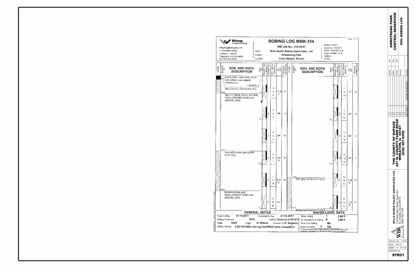
DATE :
DRAWING NO.
DS
GN.
CH
KD.
SC
ALE :
DW
N.
NA
TU
RE O
F R
EVISIO
NN
O.
DA
TE
(630) 443-7
755
St. C
harles, Illinois 6
0174
116 W
est
Main Street, S
uite 2
01
PROJECT NO.
HLF
HLF
AE
U
1
2
3
4
5
6
7
8
$FIL
ES$
TH
E C
OU
NT
Y O
F D
UP
AG
E
421 N.
CO
UN
TY F
AR
M R
OA
DW
HE
AT
ON, IL 60187
(630)
407-6
500
AR
MS
TR
ON
G P
AR
K
CO
NT
RO
L R
ES
ER
VOIR
STR21
SHEET 71 80
8/31/12
11-0125
OF
SOIL B
ORIN
G L
OG
Top Related