


Languages
Pages
Legal


User Manual
CSD3 Plus Servo Drive(Indexing)
Catalog Number(s) : CSD3-xxBX2 Rev.B

Important User Information Solid state equipment has operational characteristics differing from those of electromechanical equipment. Because of this difference, and also because of the wide variety of uses for solid state equipment, all persons responsible for applying this equipment must satisfy themselves that each intended application of this equipment is acceptable.
In no event will Rockwell Automation Korea, Ltd. be responsible or liable for indirect or consequential damages resulting from the use or application of this equipment.
The examples and diagrams in this manual are included solely for illustrative purposes. Because of the many variables and requirements associated with any particular installation, Rockwell Automation Korea, Ltd. cannot assume responsibility or liability for actual use based on the examples and diagrams.
No patent liability is assumed by Rockwell Automation Korea, Ltd. with respect to use of information, circuits, equipment, or software described in this manual.
Reproduction of the contents of this manual, in whole or in part, without written permission of Rockwell Automation Korea, Ltd., is prohibited.
Throughout this manual, when necessary, we use notes to make you aware of safety considerations.
Trademarks not belonging to Rockwell Automation Korea, Ltd. are property of their respective companies.
WARNINGIdentifies information about practices or circumstances that can cause an explosion in a hazardous environment, which may lead to personal injury or death, property damage, or economic loss.
IMPORTANT Identifies information that is critical for successful application and understanding of the product.
ATTENTION Identifies information about practices or circumstances that can lead to personal injury or death, property damage, or economic loss. Attentions help you identify a hazard, avoid a hazard, and recognize the consequence
WARNINGLabels may be located on or inside the equipment, for example, a drive or motor, to alert people that dangerous voltage may be present.
BURN HAZARDLabels may be located on or inside the equipment, for example, a drive or motor, to alert people that surfaces may be at dangerous temperatures.

Table of Contents
Preface About This Publication. . . . . . . . . . . . . . . . . . . . . . . . . . . . . . . . . . . . . . . . . P-1Who Should Use this Manual . . . . . . . . . . . . . . . . . . . . . . . . . . . . . . . . . . . P-1Additional Resources. . . . . . . . . . . . . . . . . . . . . . . . . . . . . . . . . . . . . . . . . . P-1
Chapter 1Overview Introduction . . . . . . . . . . . . . . . . . . . . . . . . . . . . . . . . . . . . . . . . . . . . . . . . . 1-1
What is indexing . . . . . . . . . . . . . . . . . . . . . . . . . . . . . . . . . . . . . . . . . . . . . 1-1Index Elements . . . . . . . . . . . . . . . . . . . . . . . . . . . . . . . . . . . . . . . . . . . . . . 1-2Indexing Types . . . . . . . . . . . . . . . . . . . . . . . . . . . . . . . . . . . . . . . . . . . . . . . 1-2Position Unit . . . . . . . . . . . . . . . . . . . . . . . . . . . . . . . . . . . . . . . . . . . . . . . . 1-3
Pulse Unit . . . . . . . . . . . . . . . . . . . . . . . . . . . . . . . . . . . . . . . . . . . . . . . 1-5User Unit . . . . . . . . . . . . . . . . . . . . . . . . . . . . . . . . . . . . . . . . . . . . . . . . 1-6
Velocity, Acceleration Time, Deceleration Time Setting . . . . . . . . . . . . . . 1-8Velocity . . . . . . . . . . . . . . . . . . . . . . . . . . . . . . . . . . . . . . . . . . . . . . . . . 1-8Acceleration . . . . . . . . . . . . . . . . . . . . . . . . . . . . . . . . . . . . . . . . . . . . . 1-9Deceleration . . . . . . . . . . . . . . . . . . . . . . . . . . . . . . . . . . . . . . . . . . . . . 1-9
Chapter 2Indexing Introduction . . . . . . . . . . . . . . . . . . . . . . . . . . . . . . . . . . . . . . . . . . . . . . . . . 2-1
Firmware Download . . . . . . . . . . . . . . . . . . . . . . . . . . . . . . . . . . . . . . . . . . 2-1Control Mode Setting . . . . . . . . . . . . . . . . . . . . . . . . . . . . . . . . . . . . . . . . . 2-2I/O Signals . . . . . . . . . . . . . . . . . . . . . . . . . . . . . . . . . . . . . . . . . . . . . . . . . . 2-3
I/O Signal Configuration . . . . . . . . . . . . . . . . . . . . . . . . . . . . . . . . . . . . 2-3Factory Defaults . . . . . . . . . . . . . . . . . . . . . . . . . . . . . . . . . . . . . . . . . . 2-6
I/O Settings . . . . . . . . . . . . . . . . . . . . . . . . . . . . . . . . . . . . . . . . . . . . . . . . . 2-7Input Signal Assignment. . . . . . . . . . . . . . . . . . . . . . . . . . . . . . . . . . . . 2-7Output Signal Assignment . . . . . . . . . . . . . . . . . . . . . . . . . . . . . . . . . . 2-8
Description of I/O Signals . . . . . . . . . . . . . . . . . . . . . . . . . . . . . . . . . . . . . . 2-9START and IMO (In Motion) . . . . . . . . . . . . . . . . . . . . . . . . . . . . . . . . . 2-9C-SP1, C-SP2 and C-SP3 . . . . . . . . . . . . . . . . . . . . . . . . . . . . . . . . . . . 2-10PAUSE . . . . . . . . . . . . . . . . . . . . . . . . . . . . . . . . . . . . . . . . . . . . . . . . . 2-11ABORT. . . . . . . . . . . . . . . . . . . . . . . . . . . . . . . . . . . . . . . . . . . . . . . . . 2-12SHOM(Start Homing), HOME(Home Sensor Signal), HOMC(Homing
Completed) . . . . . . . . . . . . . . . . . . . . . . . . . . . . . . . . . . . . . . . . . . . 2-13Travel modes . . . . . . . . . . . . . . . . . . . . . . . . . . . . . . . . . . . . . . . . . . . . . . . 2-14
Automatic Sequential travel . . . . . . . . . . . . . . . . . . . . . . . . . . . . . . . . 2-15Step Sequential Travel . . . . . . . . . . . . . . . . . . . . . . . . . . . . . . . . . . . . 2-16Selective Position Travel . . . . . . . . . . . . . . . . . . . . . . . . . . . . . . . . . . 2-17
Homing. . . . . . . . . . . . . . . . . . . . . . . . . . . . . . . . . . . . . . . . . . . . . . . . . . . . 2-18Homing Mode . . . . . . . . . . . . . . . . . . . . . . . . . . . . . . . . . . . . . . . . . . . 2-20Homing Direction . . . . . . . . . . . . . . . . . . . . . . . . . . . . . . . . . . . . . . . . 2-22
S/W Limit. . . . . . . . . . . . . . . . . . . . . . . . . . . . . . . . . . . . . . . . . . . . . . . . . . 2-24Dwell Time. . . . . . . . . . . . . . . . . . . . . . . . . . . . . . . . . . . . . . . . . . . . . . . . . 2-25RUN Functions . . . . . . . . . . . . . . . . . . . . . . . . . . . . . . . . . . . . . . . . . . . . . . 2-26Monitoring Modes for Indexing. . . . . . . . . . . . . . . . . . . . . . . . . . . . . . . . . 2-26
i Publication CSD3P-UM002A-EN-P — February 2009

ii
Index Faults . . . . . . . . . . . . . . . . . . . . . . . . . . . . . . . . . . . . . . . . . . . . . . . . 2-27Homing Fail. . . . . . . . . . . . . . . . . . . . . . . . . . . . . . . . . . . . . . . . . . . . . 2-27Homing Not Completed . . . . . . . . . . . . . . . . . . . . . . . . . . . . . . . . . . . 2-27Indexing Position Range Overflow . . . . . . . . . . . . . . . . . . . . . . . . . . . 2-28
Chapter 3Modbus Introduction . . . . . . . . . . . . . . . . . . . . . . . . . . . . . . . . . . . . . . . . . . . . . . . . . 3-1
Modbus . . . . . . . . . . . . . . . . . . . . . . . . . . . . . . . . . . . . . . . . . . . . . . . . . . . . 3-1Address Mapping . . . . . . . . . . . . . . . . . . . . . . . . . . . . . . . . . . . . . . . . . . . . 3-2Address Rule and Data Conversion . . . . . . . . . . . . . . . . . . . . . . . . . . . . . . 3-9
Address Rule . . . . . . . . . . . . . . . . . . . . . . . . . . . . . . . . . . . . . . . . . . . . 3-9Data Conversion . . . . . . . . . . . . . . . . . . . . . . . . . . . . . . . . . . . . . . . . . 3-11
Exception Code . . . . . . . . . . . . . . . . . . . . . . . . . . . . . . . . . . . . . . . . . . . . . 3-13
Chapter 4SmartJog Introduction . . . . . . . . . . . . . . . . . . . . . . . . . . . . . . . . . . . . . . . . . . . . . . . . . 4-1
Indexing . . . . . . . . . . . . . . . . . . . . . . . . . . . . . . . . . . . . . . . . . . . . . . . . . . . . 4-2Index Table . . . . . . . . . . . . . . . . . . . . . . . . . . . . . . . . . . . . . . . . . . . . . . 4-2Teaching . . . . . . . . . . . . . . . . . . . . . . . . . . . . . . . . . . . . . . . . . . . . . . . . 4-4
Appendix AParameters Introduction . . . . . . . . . . . . . . . . . . . . . . . . . . . . . . . . . . . . . . . . . . . . . . . . . A-1
Parameters list . . . . . . . . . . . . . . . . . . . . . . . . . . . . . . . . . . . . . . . . . . . . . . A-1Indexing Parameters . . . . . . . . . . . . . . . . . . . . . . . . . . . . . . . . . . . . . . . . . A-10
Publication CSD3P-UM002A-EN-P — February 2009

Preface
Read this preface to familiarize yourself with the rest of the manual.
About This Publication This manual provides detailed information for the indexing of the CSD3 Plus Servo Drive
Who Should Use this Manual
This manual is intended for engineers or technicians directly involved in the installation and wiring of the CSD3 Plus Servo Drive drive, and programmers directly involved in the operation, field maintenance, and integration of the CSD3 Plus Servo Drive drive.
If you do not have a basic understanding of the CSD3 Plus Servo Drive drive, contact your local Allen-Bradley OEMax sales representative before using this product, for information on available training courses.
Additional Resources The following documents contain additional information concerning related CSD3P products.
You can view or download publications athttp://www.oemax.co.kr or http://www.oemax.com To order paper copies of technical documentation, contact your local Allen-Bradley OEMax distributor or sales representative.
For Read This Document Publication Number
Information about the installation of your CSD3 Plus Servo Drive CSD3 Plus Servo Drive Installation Instructions CSD3-IN001
Information about the operation of your CSD3 Plus Servo Drive CSD3P Servo Drive User Manual CSD3P-UM001
Information about the new features of SmartJog 4.1 SmartJog 4.1 User Manual SMARTJOG-UM001B
1 Publication CSD3P-UM002A-EN-P — February 2009

2
Publication CSD3P-UM002A-EN-P — February 2009

Chapter1
Overview
Introduction Use this chapter to briefly understand the idea of indexing of a servo drive. This chapter also describes the elements for indexing, such as position unit and acceleration, etc.
What is indexing Servo drive is a device to control a servo motor with a pulse train or an analog signal coming from an external controller, which is responsible for the control of physical dimensions such as displacement, speed or torque. It means that a servo drive is an actuator but not a controller, just implementing the control with a command from the external controller.
An external controller determines a position, speed or torque depending on control scheme, usually based on the feedback from a servo drive. However, some applications do not require feedback-based command from the controller , but a servo drive just follows a pre-defined sequence from the controller. Especially, indexing requirement is much simpler in such applications. They just need a movement with an accurate position information regardless of other control inputs.
Now, the CSD3 Plus Servo Drive provides a simple indexing for one axis, not requiring any command from a controller, but providing programmed position control. It is quite simple function. Given an index in a parameter, then the CSD3 Plus Servo Drive starts indexing. Since any other external device is not required, the system configuration would be so simple and implemented very fast.
The CSD3 Plus Servo Drive has a special routine to provide indexing. Indexing starts to work when the control mode is set to Indexing. The CSD3 Plus Servo Drive is able to support 8 indexes with each different speed and provide various travel modes over 8 indexes. The operation can be paused or aborted by I/O signals. Also, the CSD3 Plus Servo Drive provides various homing modes.
Topic Page
Introduction 1-1
What is indexing 1-1
Index Elements 1-2
Indexing Types 1-2
Position Unit 1-3
Velocity, Acceleration Time, Deceleration Time Setting 1-8
1 Publication CSD3P-UM002A-EN-P — February 2009

1-2 Overview
Index Elements In order to make a movement, it is necessary to define four elements: a position (where to move), a velocity (how fast it moves), acceleration time and deceleration time to reach the speed and make a stop. The position is defined as a number of pulses or μm, and either in the incremental or in the absolute coordinate. Up to 8 index data can be programmed. The CSD3 supports only trapezoidal velocity profile.
Indexing Types There are two kinds of coordinate systems to express position. In the absolute coordinate system, all the Indexes are expressed based on one reference location, called as Home or Origin. In the incremental coordinate system, a position is defined with a relative distance from its previous position. For example, 20000 pulses input at the first position can result in different second positions as shown in each figure below depending on indexing type.
Velocity
Position
Acceleration Time Deceleration Time
20000
Pules Absolute IncrementalPules
10000
20000
10000
20000
30000
Publication CSD3P-UM002A-EN-P — February 2009

Overview 1-3
Position Unit The position information can be entered into the index position parameters in either pulse or user (μm) unit. A user can select either option in the 1st digit of Pr-0.18 (Position Unit & Fault Code). The selected position unit applies to all the position values used in the indexing.
The parameters affected by the position unit are shown below:
• Pr-3.09 ~ Pr-3.24: Index 1~8 position
IMPORTANT When a value which is converted from user unit to pulse unit is out of -499,999,999~+499,999,999 pulse range, a fault (Indexing Position Range Overflow) occurs and parameter values reset to zero.
Parameter No. 7-Seg. Position Value Update timing Default Range Unit
Index 1 Position High Pr-3.09 N/A N/A Immediately 0 -4,999~+4,999
pulse, μm
Index 1 Position Low Pr-3.10 N/A N/A Immediately 0 -99,999~+99,999
pulse, μm
Index 2 Position High Pr-3.11 N/A N/A Immediately 0-4,999~+4,999
pulse, μm
Index 2 Position Low Pr-3.12 N/A N/A Immediately 0 -99,999~+99,999
pulse, μm
Index 3 Position High Pr-3.13 N/A N/A Immediately 0-4,999~+4,999
pulse, μm
Index 3 Position Low Pr-3.14 N/A N/A Immediately 0 -99,999~+99,999
pulse, μm
Index 4 Position High Pr-3.15 N/A N/A Immediately 0-4,999~+4,999
pulse, μm
Index 4 Position Low Pr-3.16 N/A N/A Immediately 0 -99,999~+99,999
pulse, μm
Index 5 Position High Pr-3.17 N/A N/A Immediately 0-4,999~+4,999
pulse, μm
Index 5 Position Low Pr-3.18 N/A N/A Immediately 0 -99,999~+99,999
pulse, μm
Index 6 Position High Pr-3.19 N/A N/A Immediately 0-4,999~+4,999
pulse, μm
Index 6 Position Low Pr-3.20 N/A N/A Immediately 0 -99,999~+99,999
pulse, μm
Index 7 Position High Pr-3.21 N/A N/A Immediately 0-4,999~+4,999
pulse, μm
Publication CSD3P-UM002A-EN-P — February 2009

1-4 Overview
• Pr-5.15 ~ Pr-5.22: Moving distance After Home sensor, Homing Offset, S/W Limit(+)/(-)
The value within -499,999,999~+499,999,999 range is entered into the Index No. Position High and Low separately as shown below, where No. means a parameter number such as Pr-3.09 (Index 1 Position High) or Pr-3.10 (Index 1 Position Low).
• Index No. Position High : 10^5~10^8 digits of an Index command, -4,999~+4,999
• Index No. Position Low : 10^0~10^4 digits of an Index command, -99,999~+99,999
When a value out of the range -99,999~+99,999 is entered into the index position, the sign of the entered value is set in the Index No. Position High. If the value is within the range, the sign is set in the Index No. Position Low.
• When a user tries to enter a negative value into an Index No. Position Low while Index No. Position High is not equal to zero by using the built-in operator, the parameter value is not changed.
Index 7 Position Low Pr-3.22 N/A N/A Immediately 0 -99,999~+99,999
pulse, μm
Index 8 Position High Pr-3.23 N/A N/A Immediately 0-4,999~+4,999
pulse, μm
Index 8 Position Low Pr-3.24 N/A N/A Immediately 0 -99,999~+99,999
pulse, μm
Parameter No. 7-Seg. Position Value Update timing Default Range Unit
Moving distance After Home Sensor High Pr-5.15 N/A N/A Servo Off 0-4,999~+4,999
pulse, μm
Moving distance After Home Sensor Low Pr-5.16 N/A N/A Servo Off 0 -99,999~+99,999
pulse, μm
Homing Offset High Pr-5.17 N/A N/A Servo Off 0-4,999~+4,999
pulse, μm
Homing Offset Low Pr-5.18 N/A N/A Servo Off 0 -99,999~+99,999
pulse, μm
Software Negative Limit High Pr-5.19 N/A N/A Servo Off 0-4,999~+4,999
pulse, μm
Software Negative Limit Low Pr-5.20 N/A N/A Servo Off 0 -99,999~+99,999
pulse, μm
Software Positive Limit High Pr-5.21 N/A N/A Servo Off 0-4,999~+4,999
pulse, μm
Software Positive Limit Low Pr-5.22 N/A N/A Servo Off 0 -99,999~+99,999
pulse, μm
Publication CSD3P-UM002A-EN-P — February 2009

Overview 1-5
• When a user enters a value other than 0 into Index No. Position High while Index No. Position Low is smaller than zero, the parameter value is not changed.
Example)
Pulse Unit
Set the 1st digit of Pr-0.18 (Position Unit & Fault Code) to ‘0’ and enter the number of pulses into the Index parameter. The example below describes how to use the High and Low parameters of Index No. Position (pulse).
EXAMPLE
Example1)
When Index No. Position High is equal to zero,
Index No. Position (pulse) = Index No. Position Low
Example2)
When Index No. Position High is not equal to zero and
Index No. Position Index No. Position High Index No. Position Low
-12,345,678 -123 45678
-12,345 0 -12345
Parameter No. 7-Seg. Position Value Detail Update timing Default Range Unit
Position Unit& Fault Code
Pr-0.18
10 Position Unit(pulse)
Power Off/On
0 0~1 N/A1 Position Unit(User Unit : um)
2
0 Fault Code
0 0~2 N/A1 Index Number
2 Fault Code & Index Number
Pulse reference of User unit input
Pr-0.23Pulse reference of User unit input
Power Off/On 00~999,999
pulse
Distance reference of User unit input
Pr-0.24Distance reference of User unit input
Power Off/On 00~65,535
μm
Publication CSD3P-UM002A-EN-P — February 2009

1-6 Overview
Index No. Position High is larger than zero and Index No. Position Low is larger than zero,
Index No. Position (pulse) = Index No. Position High*10^5+ Index No. Position Low
When Index No. Position High is not equal to zero and
Index No. Position High is smaller than zero and Index No. Position Low is larger than zero,
Index No. Position (pulse) = Index No. Position High*10^5- Index No. Position Low
User Unit
A servo drive uses a number of pulses to express a moving distance. However, it is not so convenient to check a movement in pulse unit since user unit (μm) is actually used to express a moving distance. The CSD3 Plus Servo Drive supports either a number of pulses or user (μm) to express a moving distance. When a movement is given in a number of pulses, then the servo makes a movement based on the number of pulses directly. However, set the 1st digit of Pr-0.18 (Position Unit & Fault Code) to ‘1’, then the servo needs to convert user (μm) into a number of pulses when a position is given in user (μm). The conversion requires a coefficient to show the correlation between μm and a number of pulses. The Pr- 0.23 (Pulse user reference: 0~999,999 pulses) and Pr-0.24 (Distance user reference: 0~65,535 μm) are the parameters to set the coefficient.
• User reference: A μm = B pulses
• Index No. Position (pulse) = Index No. Position (μm) * Pr-0.23 value (pulse) / Pr-0.24 value (μm)
Example)
User reference: 300 μm = 1,000 pulses
Pr-0.23 value (pulse): 1,000
Pr-0.24 value (μm): 300
Index 1 Position: 7,320 μm
Index 1 Position (pulse) = 7,320 μm * 1,000 pulses / 300 μm
IMPORTANT When a value which is converted from user unit to pulse unit is out of -499,999,999~+499,999,999 pulse range, a fault (Indexing Position Range Overflow) occurs and parameter values reset to zero.
Publication CSD3P-UM002A-EN-P — February 2009

Overview 1-7
= 24,400 pulses
Publication CSD3P-UM002A-EN-P — February 2009

1-8 Overview
Velocity, Acceleration Time, Deceleration Time Setting
A user can enter total 8 velocities for 8 indexes. However, there are only one Acceleration Time and one Deceleration Time.
Velocity
Enter velocity t for each movement into the velocity parameter. The input range is 0~5000 and its unit is rpm. For the Index 1 to the Index 7, use Pr-2.05~Pr-2.11 to enter its velocity. For the Index 8, use Pr-2.18.
Parameter No. 7-Seg. Position Value Update timing Default Range Unit
Contact speed command 1/Index 1 Velocity
Pr-2.05 N/A N/A Immediately 100 -5,000~5,000
rpm
Contact speed command 2/Index 2 Velocity
Pr-2.06 N/A N/A Immediately 200 -5,000~5,000
rpm
Contact speed command 3/Index 3 Velocity
Pr-2.07 N/A N/A Immediately 300 -5,000~5,000
rpm
Contact speed command 4/Index 4 Velocity
Pr-2.08 N/A N/A Immediately 400 -5,000~5,000
rpm
Contact speed command 5/Index 5 Velocity
Pr-2.09 N/A N/A Immediately 500 -5,000~5,000
rpm
Contact speed command 6/Index 6 Velocity
Pr-2.10 N/A N/A Immediately 600 -5,000~5,000
rpm
Contact speed command 7/Index 7 Velocity
Pr-2.11 N/A N/A Immediately 700 -5,000~5,000
rpm
Index 8 Velocity Pr-2.18 N/A N/A Immediately 800 0~5,000 rpm
Publication CSD3P-UM002A-EN-P — February 2009

Overview 1-9
Acceleration
A user can define only one Acceleration time for all the 8 indexes. The range of Index Acceleration Time (Pr-2.19) is 0~20,000 and its unit is msec. The Acceleration slope is calculated by velocity and Acceleration time as shown below.
Index No. Acceleration slope (pulse/sec/sec) = [Index No. Welocity (revolution/min) / 60 * Motor ppr (pulse/revolution)] / (Acceleration time (msec) * 0.001)
Deceleration
A user can define only one Deceleration time for all the 8 indexes. The range of Index Deceleration Time (Pr-2.20) is 0~20,000 and its unit is msec. The Deceleration slope is calculated by velocity and Deceleration time as shown below.
Index No. Deceleration slope (pulse/sec/sec) = [Index No. Velocity (revolution/min) / 60 * ppr (pulse/revolution)] / (Deceleration time(msec) * 0.001)
Parameter No. 7-Seg. Position Value Update timing Default Range Unit
Index Acceleration Time Pr-2.19 N/A N/A Immediately 200 0~20,000 msec
Parameter No. 7-Seg. Position Value Update timing Default Range Unit
Index Deceleration Time Pr-2.20 N/A N/A Immediately 200 0~20,000 msec
Publication CSD3P-UM002A-EN-P — February 2009

1-10 Overview
Publication CSD3P-UM002A-EN-P — February 2009

Chapter 2
Indexing
Introduction This chapter describes the operation of the CSD3 Plus Servo Drive.
For indexing, the CSD3 servo drive uses general servo parameters, position data, travel mode and I/O signals. Since general servo parameters are also used for Indexing, refer to The CSD3 Servo Drive User Manual (The CSD3P-UM001) for more information about parameters related to general servo operations.
Firmware Download When a user uploads the firmware (which is downloaded from, Rockwell Automation Korea Allen-Bradley OEMax product homepage, www.oemax.co.kr) for indexing to the CSD3 Plus Servo Drive, there occur several errors including checksum error or fault.
To solve the problem, a user needs to do power cycling two times.
Topic Page
Introduction 2-1
Firmware Download 2-1
Control Mode Setting 2-2
I/O Signals 2-3
I/O Settings 2-7
Description of I/O Signals 2-9
Travel modes 2-14
Homing 2-18
S/W Limit 2-24
Dwell Time 2-25
RUN Functions 2-26
Monitoring Modes for Indexing 2-26
Index Faults 2-27
1 Publication CSD3P-UM002A-EN-P — February 2009

2-2 Indexing
Control Mode Setting Indexing mode is added to the CSD3 Plus Servo Drive. The table below shows all the control modes supported in the CSD3 Plus Servo Drive.
Basic Control Mode Combinational Control Mode
Display Description Display Description
Control Mode
Position mode Speed + position mode
Speed mode Torque + speed mode
Torque mode Torque + position mode
Multi-step speed mode
Multi-step speed + position mode
Indexing modeMulti-step speed + speed mode
Multi-step speed + torque mode
Parameter No. 7-Seg. Position Value Detail Update timing Default Range Unit
Control mode Pr-0.00
1 P Position mode
Power Off/On P N/A
2 S Speed mode
3 T Torque mode
4 C Contact Speed mode
5 I Indexing mode
Publication CSD3P-UM002A-EN-P — February 2009

Indexing 2-3
I/O Signals I/O Signals are actual control signals for Indexing, i.e. starting a movement and making a stop. Once all index data is set up, I/O signals control indexing.
I/O Signal Configuration
A user can configure I/O signals in the CSD3 servo drive.
Digital Input signals
Type Description Mode
</SV-ON>Servo-ON
If input is ON, the power is applied to the servo motor, and if OFF, the power is cut off. All
</A-RST>Fault Reset
Fault reset Resets the servo fault status. All
</G-SEL>Gain group conversion
Use 2 group gain where the input is on, and use existing gain where the input is off. Convert 2 types of gain groups.
All
</P-TL>Limit forward torque
If signal is ON, limit forward torque by the setting of [Pr-4.03]. All
</N-TL>Limit reverse torque
If signal is ON, limit reverse torque by the setting of [Pr-4.04]. All
<P-OT>Prohibit forward operation
If load mechanical part reaches the forward limit, this prevents the motor from moving further to that direction. P S C I(1)
<N-OT>Prohibit reverse operation
If load mechanical part reaches the reverse limit, this prevents the motor from moving further to that direction.
P S C I
</P-CON>P/PI control conversion
Converts the speed controller from PI controller type into P controller type. Used to provide better response performance by prohibiting the overshoot in transient response.
P S C I
</C-SEL>Control mode conversion
Used to convert control mode when used as combinational control mode. Combinational Control Mode Only
</C-DIR></C-SP1></C-SP2></C-SP3></C-SP4>Terminal speed command
The rotation direction</C-DIR> and rotation speed </C-SP1 to /C-SP4> of the motor are determined by the above input in terminal speed control mode. Rotation speed of </C-SP1 to /C-SP3> is set in [Pr-2.05 to Pr-2.11]. Rotation speed of </C-SP4> is set by analog speed command voltage. </C-DIR> is used to change motor rotation direction in speed control mode.
(Indexing) The combination of </C-SP1>, </C-SP2> and </C-SP3> selects one of eight position commands.
C, I(/C-DIR, /C-SP4 is not available.)
</Z-CLP>Zero clamp
Disregard the input value if in speed control, analog command value is smaller than the value set at speed zero clamp level [Pr-5.04].
S
</INHIB>Inhibit pulse command
Disregard position command pulse where the signal is ON. P
</ABS-DT>Absolute Encoder Data Transmission
Transmits absolute encoder data to host controller through EA, EB when the signal is ON. P I
</PCLR> /ABORT
Clear position command, position feedback, and position error. (Indexing) Abort Indexing
P I
Publication CSD3P-UM002A-EN-P — February 2009

2-4 Indexing
Digital Output signals
/STARTControl motor rotation start or stop by using terminal signal in speed or terminal speed control mode.(Indxing)Start Motion or Indexing
S C I
/GEARIn position control mode, the 2nd electronic gear parameters [Pr-3.05] and [Pr-3.06] are used when input is ON. The basic electronic gear parameters [Pr-3.01] and [Pr-3.02] are used when input is OFF. Switch between two electronic gear ratios.
P
/HOME Home Sensor Signal I
/SHOM Start Homing I
/PAUSE Pause Indexing I
(1) P: Position mode, S: Speed mode, C: Contact Speed mode, I: Indexing mode
Signal Description Mode
</P-COM (+, -)>Positioning Completion detection
It is ON when the position error is within the set value of output width of position completion signal, [Pr-5.00],
P I
</NEAR (+, -)>Position approach detection
It is ON when the position error is within the setting value of output width of position approach signal, [Pr-5.01].
P I
</V-COM (+, -)>Speed coincidence detection
It is ON when error between speed command and motor rotation speed is within the set value of output width of speedcoincidence signal, [Pr-5.02].
P S C I
</TG-ON (+, -)>Rotation detection
It is ON when the motor rotates at speeds higher than the set value of rotation detection level, [Pr-5.03]. All
</T-LMT (+, -)>Torque limit detection
It is ON when it reaches the set torque limit. All
</V-LMT (+, -)>Speed limit detection
It is ON when it reaches the set speed limit. All
<BK (+, -)>Breaker control
Signal for the control of brake mounted internally or externally on the servo motor. All
</WARN (+, -)>Warning detection
It is ON if a servo warning is detected, All
</HOMC (+, -)>Homing Completed
It is ON when the home is defined. I
</IMO (+, -)>In Motion
It is ON in motion. I
Publication CSD3P-UM002A-EN-P — February 2009

Indexing 2-5
Fault Code Output
Signal Description
AL1 In the Indexing mode, the 2nd digit of Pr-0.18 determines what the output is.-. 0 : Fault Code -. 1 : Index Number
This is maintained during indexing and also until it starts a new indexing.The default is ‘0’.
-. 2 : Fault Code & Index Number Index Number during indexingFault Code if not under indexing
AL2
AL3
Fault-SG
Parameter No. 7-Seg. Position Value Detail Update timing Default Range Unit
Position Unit & Fault Code
Pr-0.18
10 Position Unit(pulse)
Power Off/On
0 0~1 N/A1 Position Unit(User Unit : um)
2
0 Fault Code
0 0~2 N/A1 Index Number
2 Fault Code & Index Number
/AL3 /AL2 /AL1
Index 1 OFF OFF OFF
Index 2 OFF OFF ON
Index 3 OFF ON OFF
Index 4 OFF ON ON
Index 5 ON OFF OFF
Index 6 ON OFF ON
Index 7 ON ON OFF
Index 8 ON ON ON
Publication CSD3P-UM002A-EN-P — February 2009

2-6 Indexing
Factory Defaults
Factory defaults are default settings for general servo functions, which are different from Indexing. These should be configured properly before using Indexing.
Factory Defaults
The table below shows sample of I/O Configuration when there is no limit switch but Home sensor. And the Indexes are assigned by I/O selection signals.
PIN No Input PIN No Output
3 DI #1 /SV-ON 41-42 DO #1 /P-COM
4 DI #2 43-44 DO #2 /TG-ON
5 DI #3 47-48 DO #3 BK
6 DI #4 P-CON
7 DI #5 /A-RST
8 DI #6 /N-TL
9 DI #7 /P-TL
PIN No Input PIN No Output
3 DI #1 /SV-ON 41-42 DO #1 /P-COM
4 DI #2 /HOME 43-44 DO #2 /HOMC
5 DI #3 /SHOM 47-48 DO #3 /IMO
6 DI #4 /START
7 DI #5 /C-SP1
8 DI #6 /C-SP2
9 DI #7 /C-SP3
Publication CSD3P-UM002A-EN-P — February 2009

Indexing 2-7
I/O Settings Input Signal Assignment
Refer to the below tables to allocate sequence input signals.
Set values
Input channel number
Always valid
DI#7 DI#6 DI#5 DI#4 DI#3 DI#2 DI#1
Always invalid
CN1 pin number 9 8 7 6 5 4 3
As shown on the table below, relevant functions are already assigned to sequence input parameters and the number of digits of the related configuration window; the user enters relevant function by selecting a value in the range of ‘1-8’ , excluding value ‘0’.
For example, if a certain function is to be applied to Pin 5 of CN1, the parameter pertaining to that signal should be looked up from the table below and the set value entered as ‘3’.
If the input signal function is not to be used, enter ‘0’.
If the input signal should be always ON regardless of wiring, enter ‘8’.
The table below is a summary of parameters for each function and the 7-segment digits displayed on the configuration window. Be sure that the digits on the configuration window match the parameters relevant to each signal.
7-segment 4th digit 3rd digit 2nd digit 1st digit
Configuration window of each parameter
1</P-CON>Initial value: 4
<N-OT>Initial value:8
<P-OT>Initial value:8
</SV-ON>Initial value: 1
2 </C-SEL></P-TL>Initial value:7
</N-TL>Initial value: 6
</A-RST>Initial value: 5
3 </C-SP3> </C-SP2> </C-SP1> </C-DIR>
4</PCLR>or </ABORT>
</G-SEL> </INHIB> </Z-CLP>
5 </GEAR> </C-SP4> </START> </ABS-DT>
6 N/A </PAUSE> </SHOM> </HOME>
Publication CSD3P-UM002A-EN-P — February 2009

2-8 Indexing
Output Signal Assignment
Refer to the below tables to allocate sequence output signals.
Configuration example
Value ‘7’ is set at the 4th digit of the configuration window for parameter[Pr-0.05].This value has been set to use the </P-CON> function; it means that the pin DI#7 of CN1 is to be used as input pin.
Applicable modes
ALL Other details Servo-OFF>Configure>Reapply power>Completed
Detailed description
Refer to the Chapter 5-2 of the CSD3 Plus Servo Drive User Manual (CSD3P-UM001).
7-segment 4th digit 3rd digit 2nd digit 1st digit
Configuration window of each parameter
1 </V-COM></BK>Initial value 3
</TG-ON>Initial value: 2
</P-COM>Initial value: 1
2 </WARN> </NEAR> </ V-LMT> </T-LMT>
3 N/A N/A </IMO> </HOMC>
Configuration example
Value ‘3’ has been set as the 4th digit on the configuration window of parameter [Pr-0.11].This value is set to output the </NEAR> signal; it means that pin 47 and 48 of CN1 are to be used as output pins.
Applicable modes
ALL Other detailsServo-OFF > Configuration>Reapply power > Completed
Detailed description
Refer to the Chapter 5-2 of the CSD3 Plus Servo Drive User Manual (CSD3P-UM001).
Publication CSD3P-UM002A-EN-P — February 2009

Indexing 2-9
Description of I/O Signals
START and IMO (In Motion)
The START is an input signal to start indexing and IMO is an output signal to indicate that the indexing is working. When the active going edge of the START signal is detected, the CSD3 Plus Servo Drive starts the indexing and gives IMO output. The START is used to initiate the travel mode or to clear pause.
When the CSD3 Plus Servo Drive is under homing or motion, the START signal is ignored. The IMO signal is ON during the servo drive is in motion, pause or dwell.
Motor Speed
/START
Servo(/SV-ON)
> 8ms
> 50ms
OFF ON
OFF ON OFF
In Motion(/IMO)
In Position(/P-COM)
Motor Speed
/START
may change depending on In Position Range
ON OFF
ON
ON ON
OFF
OFF OFF
OFF
Publication CSD3P-UM002A-EN-P — February 2009

2-10 Indexing
C-SP1, C-SP2 and C-SP3
The C-SP1, C-SP2 and C-SP3 are selection signals to define an index among 8 indexes in the index table. In the selective position travel mode, the CSD3 servo drive determines the index by using the combination of these signals at the active going edge of the START signal. The C-SP1& C-SP2& C-SP3 signals are valid only when the signals maintain their status for at least 4ms before the active going edge of START signal and at least for 8 msec after the active going edge of START signal. If the C-SP1, C-SP2 and C-SP3 signals are detected during motion, they are ignored.
Index
/START
/C-SP1
/C-SP2
/C-SP3
> 4ms
Index 2
> 8ms
7ms~9ms
ONOFF OFF
OFF
OFFON
ONOFF
Publication CSD3P-UM002A-EN-P — February 2009

Indexing 2-11
PAUSE
When the system detects the active going edge of a PAUSE signal during indexing, the motor starts to be decelerated to stop in a pre-defined deceleration time while remembering the index. The IMO is still ON because the motion is not completed yet.
When the CSD3 Plus Servo Drive detects the active going edge of START signal during pause, the indexing is enabled again to reach the index position with the motion profiles of acceleration time, velocity and deceleration time.
When the ABORT signal turns ON during pause, the indexing is aborted and the indexing is terminated. The system becomes ready for a new indexing. Please refer to Abort for more information. The pause is enabled at the active going edge of the PAUSE signal, and IMO (In Motion) is still active during pause.
Motor Speed
Index
Servo(/SV-ON)
/START
In Position(/P-COM)
/HOMC ON
In Motion(/IMO)
/C-SP1
/C-SP3
/C-SP2
/PAUSE
Index 3Position
Index 4Position
OFF ON
OFF
OFF
OFF ON
ON
OFF OFF OFF OFF
Index 3 Index 4
ON ON ON
Position
OFF ON OFF
OFF OFF OFFON ON ON ON
ONONOFF OFF OFF
Publication CSD3P-UM002A-EN-P — February 2009

2-12 Indexing
ABORT
The Abort is a signal to cancel indexing. The existing /PCLR signal is used for Abort. When the ABORT signal turns ON during indexing, the motor starts to be decelerated and stops. The indexing is aborted. The IMO signal turns OFF as well. The Abort is enabled at the active going edge of the /ABORT input. The ABORT is only available in the Travel mode, not in the Homing mode. When the ABORT is enabled, IMO (In Motion) signal becomes OFF.
Motor Speed
Index
Servo(/SV-ON)
/START
In Position(/P-COM)
/HOMC ON
In Motion(/IMO)
/C-SP1
/C-SP3
/C-SP2
/ABORT
Index 3Position
Index 4Position
OFF ON
OFF
OFF
OFF ON
ON
OFF OFF OFF
Index 4
ON ON
Position
OFF ON OFF
OFF OFFON ON ON
ONONOFF OFF OFF
Index 3
Publication CSD3P-UM002A-EN-P — February 2009
Indexing 2-13
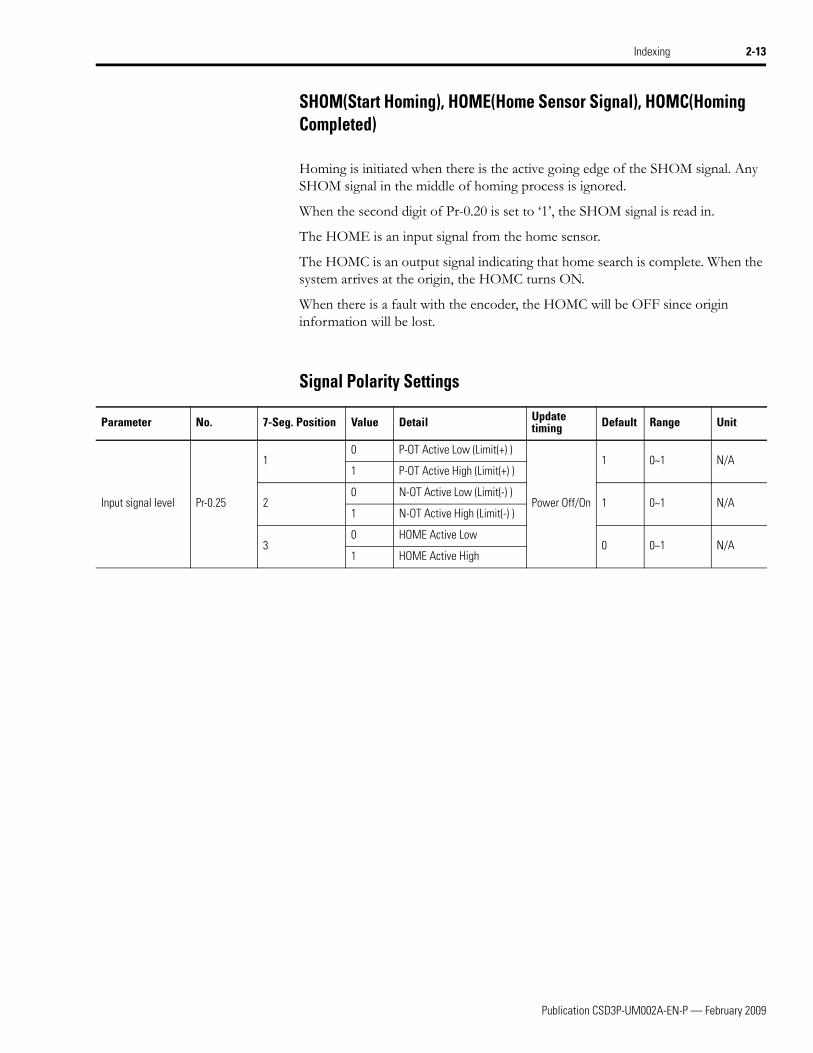
SHOM(Start Homing), HOME(Home Sensor Signal), HOMC(Homing Completed)
Homing is initiated when there is the active going edge of the SHOM signal. Any SHOM signal in the middle of homing process is ignored.
When the second digit of Pr-0.20 is set to ‘1’, the SHOM signal is read in.
The HOME is an input signal from the home sensor.
The HOMC is an output signal indicating that home search is complete. When the system arrives at the origin, the HOMC turns ON.
When there is a fault with the encoder, the HOMC will be OFF since origin information will be lost.
Signal Polarity Settings
Parameter No. 7-Seg. Position Value Detail Update timing Default Range Unit
Input signal level Pr-0.25
10 P-OT Active Low (Limit(+) )
Power Off/On
1 0~1 N/A1 P-OT Active High (Limit(+) )
20 N-OT Active Low (Limit(-) )
1 0~1 N/A1 N-OT Active High (Limit(-) )
30 HOME Active Low
0 0~1 N/A1 HOME Active High
Publication CSD3P-UM002A-EN-P — February 2009

2-14 Indexing
Travel modes The CSD3 servo drive can store 8 indexes and provide 3 types of travel modes for the 8 indexes. The three types are Automatic Sequential travel, Step Sequential travel, and Selective position travel. Except the Selective position travel, 8 indexes are pre-defined in a memory. The Selective position travel determines 8 indexes by using I/O signals.
.
AttentionThere occurs a fault when a user tries any indexing without Homing operation completed (i.e. when HOMC (Homing Completed) is not enabled). Refer to Homing Not Completed on page 2-27 for more information about the fault.
Parameter No. 7-Seg. Position Value Detail Update timing Default Range Unit
Indexing Mode Pr-0.17
10 Absolute
Power Off/On
0 0~1 N/A1 Incremental
2
0 Automatic Sequential travel
2 0~2 N/A1 Step Sequential Travel
2 Selective position travel
Publication CSD3P-UM002A-EN-P — February 2009

Indexing 2-15
Automatic Sequential travel
In this mode, the motor automatically travels over 8 indexes according to the Index table. When there is a START signal, the motor moves to the index 1 position and stops, and automatically moves to the index 2 position. In the same manner, it repeats until it arrives at the last index. The duration of stop at each index depends on the Dwell time defined in the index data. IMO is active when the movement starts and maintains the state until the last index. If a user wants to use less than 8 indexes, he can enter the number of indexes into the parameter Pr-0.22 (Number of indexes). The default is '8'.
Parameter No. 7-Seg. Position Value Update timing Default Range Unit
Number of Indexes Pr-0.22 Servo Off 8 1~8 N/A
Motor Speed
Index
Servo(/SV-ON)
Dwell
/START
In Position(/P-COM)
Index1 Index2 Index3 Index2Index1Index8
Dwell2 Dwell8 Dwell2
Index4 Index7
Dwell7
OFF ON ON
OFF ON ONOFF OFF OFF
/HOMC ON ON
In Motion(/IMO)
OFF OFFOFF OFF OFF OFF OFFON ON ON ON ON ON ON ON
OFF ON ON ONOFF
Dwell3Dwell1 Dwell1
Publication CSD3P-UM002A-EN-P — February 2009

2-16 Indexing
Step Sequential Travel
In this mode, whenever there is the START signal, it moves to the next index, not like the Automatic Sequential travel where only one START signal is required to move over all the Indexes. Just like the Automatic Sequential travel, the motor travels over 8 indexes according to the Index table, but each START signal is required for each movement.
Whenever it arrives at each position, the IMO signal is turned OFF.
Motor Speed
Index
Servo(/SV-ON)
/START
In Position(/P-COM)
Index1 Index2 Index3 Index2Index1Index8
OFF ON ON
OFF ON ONOFF OFF OFF
/HOMC ON ON
In Motion(/IMO)
OFF OFFOFF OFF OFF OFF OFFON ON ON ON ON ON ON ON
OFF ON ON ONOFF
OFF ON ON ONOFF OFF OFF ON OFF ON
ON OFF ON ONOFF OFF OFF ON OFF OFF
Index4
Publication CSD3P-UM002A-EN-P — February 2009

Indexing 2-17
Selective Position Travel
The 8 indexes are determined by the combination of I/O signals, i.e. C-SP0, C-SP1 and C-SP2 when the CSD3 servo drive detects the active going edge of the START signal.
This is an example to show how the motor travels over Indexes stored in the memory according the combination of selection signals. The motor will move to each index in order.
Index 5 --> Index 7 --> Index 3 --> Index 4 --> Index 1
C-SP2 C-SP1 C-SP0 Index
OFF OFF OFF Index 1 Position
OFF OFF ON Index 2 Position
OFF ON OFF Index 3 Position
OFF ON ON Index 4 Position
ON OFF OFF Index 5 Position
ON OFF ON Index 6 Position
ON ON OFF Index 7 Position
ON ON ON Index 8 Position
Motor Speed
Index
Servo(/SV-ON)
/START
In Position(/P-COM)
OFF ON
OFF ON ONOFF OFF
/HOMC ON
In Motion(/IMO)
OFF OFF OFF OFF OFFON ON ON ON ON ON
OFF ON ON OFF
OFF ON OFF ON OFF ON
ON OFF ONOFF ON OFF
/C-SP1
/C-SP3
/C-SP2
Index 5 Index 7 Index 3 Index 4 Index 1
OFF
ON
ON
ON
OFF OFF
OFF OFF
OFF OFF
Publication CSD3P-UM002A-EN-P — February 2009

2-18 Indexing
Homing During indexing, all 8 indexes are defined based on a single position reference which is called ‘origin’. Home Search is a movement to find and set the origin. After it finds HOME and defines the origin, the position of the origin is set to “0”. There are several ways to find the origin and the CSD3 Plus Servo Drive provides 8 kinds of home search methods.
For an appropriate homing operation, a user must set up the following parameters:
• Homing Mode (Pr-0.19), Homing Direction(Pr-20 7-Seg. 1st Digit)
• Homing Start Option(Pr-20 7-Seg. 2nd Digit)
• 1st Homing Velocity(Pr-2.16)
• 2nd Homing Velocity(Pr-2.17)
• Stopper Torque Threshold(Pr-4.09) - Optional
• Elapsed time after Stopper Torque Threshold(Pr-4.10) - Optional
• Moving distance After Home Sensor(Pr-5.15, Pr-5.16) - Optional
• Home Offset(Pr-5.17, Pr-5.18) - Optional
Parameter No. 7-Seg. Position Value Detail Update timing Default Range Unit
Homing Mode Pr-0.19 1
0 Mode 0 : None
Power Off/On 1 0~8 N/A
1Mode 1: To Home sensor/Back to Marker
2Mode 2: To Limit sensor/Back to Marker
3Mode 3: To Home sensor/Fwd to Marker
4Mode 4: To Limit sensor/Fwd to Marker
5 Mode 5: Stopper
6Mode 6: To Stopper/Back to Marker
7Mode 7: To Home sensor/Move/Back to Marker
8 Mode 8: Marker
Homing Option Pr-0.20
10 Homing Direction : (-), CW
Power Off/On
1 0,1 N/A1 Homing Direction : (+), CCW
20 Homing start by Servo ON
1 0,1 N/A1 Homing start by SHOM
Homing Time Limit Pr-0.21 N/A N/A Homing Time Limit
Servo Off
60 0~60,000 sec
1st Homing Velocity
Pr-2.16 N/A N/A 1st homing Velocity 100 0~5,000 rpm
2nd Homing Velocity
Pr-2.17 N/A N/A 2nd homing Velocity 15 0~5,000 rpm
Publication CSD3P-UM002A-EN-P — February 2009

Indexing 2-19
With an Incremental motor, the position feedback is set to ‘0’ when homing operation is complete (If offset is ‘0’).
.
AttentionThere occurs a fault when a user tries any indexing without Homing operation completed (i.e. when HOMC (Homing Completed) is not enabled). Refer to Homing Not Completed on page 2-27 for more information about the fault.
AttentionWith an Absolute motor, the position feedback is set to ‘0’ even after homing operation is complete and there is no reset for the multi turn data of the absolute encoder. The multi turn data of Absolute motor is not automatically reset. Instead, it can be reset only by a user.
AttentionIn the homing mode which uses the sensor for homing, if homing is started outside of a sensor, homing can not be successfully completed.
N-Limit Sensor HOME Sensor P-Limit Sensor
Publication CSD3P-UM002A-EN-P — February 2009

2-20 Indexing
Homing Mode
The CSD3 Indexing supports 8 homing modes by using Home Sensor, Limit(+)/(-) Sensor, Stopper, and Marker, etc.
Homing Mode 0: None
The Homing Mode 0 does not use Home Search. When the homing start option of the Pr-0.20 is set to ‘0’, the CSD3 servo drive defines the position where it is as the origin when a drive is enabled. When the homing start option of the Pr-0.20 is set to ‘1’, the position when there is the SHOM signal is set to the origin.
Homing Mode 1: To Home Sensor / Back to Marker (default)
Homing Mode 1 uses Home Sensor and Marker to define the origin
When Home Search is started, the motor moves toward the Homing Direction (Pr-0.20) at 1st Homing Velocity (Pr-2.16) until it detects the Home Sensor. At that time, the motor is decelerated and stops, and moves toward reverse direction at 2nd Homing Velocity (Pr-2.17). When it loses the signal input from Home sensor and meets the first Marker, it is decelerated and stops, and returns to the positon where it detects the active going edge of the first Marker.
Homing Mode 2: To Limit Sensor / Back to Marker
The Homing Mode 2 uses Limit Sensor (+) or (-) and Marker.
Only the limit sensor installed in the homing direction is used and Hardware limit fault is disabled. The operational principle is the same as the Homing mode 1, only except that the limit sensor is used instead of HOME sensor input.
Homing Mode 3: To Home Sensor / Fwd to Marker
Similar to the Homing mode 1, the Homing Mode 3 also uses Home Sensor and Marker to define the origin. However, its mechanism is different.
When it detects HOME sensor input, the speed is decelerated to 2nd Homing Velocity and it is maintained until it detects the active going edge of Marker, then it
Speed
Home Sensor
Marker
Publication CSD3P-UM002A-EN-P — February 2009

Indexing 2-21
is decelerated and stops and moves backward to the position where it detects the active going edge of Marker.
Homing Mode 4: To Limit Sensor / Fwd to Marker
Similar to the Homing mode 2, the Homing Mode 4 also uses Limit Sensor (+) or (-) and Marker. The limit sensor in the homing direction is used and Hardware limit fault is disabled. However, its operational principle is almost the same as the Homing mode 3, only except that the limit sensor is used instead of HOME sensor input.
Homing Mode 5: Stopper
The Homing Mode 5 uses the Stopper to make mechanical stop.
When Home search starts, it moves toward Homing Direction at the 1st Homing Velocity until it detects a Stopper. When its torque is maintained higher than Stopper Torque Threshold for the Elapsed time after Stopper Torque Threshold, it stops and the origin is defined at the position where it stops. The Stopper Torque Threshold is defined in the parameter Pr-4.09.
Homing Mode 6: To Stopper / Back to Marker
The Homing Mode 6 uses the Stopper and Marker. The operation is similar to the Homing Mode 5, but this mode makes backward movement until it detects the falling edge of Marker when its torque is maintained higher than Stopper Torque Threshold for the Elapsed time after Stopper Torque Threshold. After it detects the active going edge of Marker, it is decelerated and stops, and returns to the the positon where it detects the active going edge of the first Marker.
Speed
Home Sensor
Marker
Speed
Stopper
Speed
Stopper
Marker
Publication CSD3P-UM002A-EN-P — February 2009

2-22 Indexing
Homing Mode 7: To Home Sensor / Move / Back to Marker
The Homing Mode 7 uses Home Sensor and Moving distance after home sensor, and Marker, just as the Homing mode 3.
Sometimes, the distance is very short between HOME sensor and Marker, so it may miss to detect the first Marker. To prevent this, this mode has one more parameter to define a minimum distance to detect Marker. The minimum distance is defined as a time in the parameter Pr-4.10. After it detects Home input, the speed is decelerated to the 2nd Home speed and it is maintained until it detects the active going edge of Marker. The active going edge of Marker is set to the origin.
Homing Mode 8: Marker
The Homing Mode 8 uses only Marker. This mode doesn’t need any extra sensors, such as HOME sensor or Limit (+) or (-). When Home search starts, it moves toward Homing Direction at the 2nd Homing Velocity. When it detects Marker, it makes stop with deceleration. It moves back to the position where it detects the active going edge of Marker and sets up the position as the origin.
Homing Direction
A user can select the Homing direction, either forward direction (position increase, CCW) or backward direction (position decrease, CW).
Homing direction determines the limit sensor to use in a homing mode.
Homing Direction (Pr-20 7-Seg. 1st Digit : 1) : forward direction (position increase, CCW) Limit Sensor used for homing: Limit Sensor (+)
Homing Direction(Pr-20 7-Seg. 1st Digit : 0) : backward direction (position decrease, CW) Limit Sensor used for homing: Limit Sensor (-)
Speed
Home Sensor
Marker
Moving distanceafter home sensor
Speed
Marker
Publication CSD3P-UM002A-EN-P — February 2009

Indexing 2-23
Homing Start Option
A user can select how to start homing, either with Start Homing Signal (/SHOM) input or Servo-ON.
When a user selects Start Homing Signal (/SHOM) input option, homing is started when there is the Start Homing Signal (/SHOM) input. However, during Indexing or Homing, the Start Homing Signal (/SHOM) is ignored. Even when Homing Completed Signal(/HOMC) is enabled after previous homing, homing is started again whenever there is the Start Homing Signal (/SHOM) input.
When a user selects Servo-ON as Homing Start Option, homing is started only when the Homing Completed Signal(/HOMC) is disabled. If the Homing Completed Signal(/HOMC) is enabled, homing is not started.
• Homing Start Option (Pr-0.20 7-Seg. 2nd Digit : 0): Homing is started when the servo drive is turned ON
• Homing Start Option (Pr-0.20 7-Seg. 2nd Digit : 1): Homing is started when the active going edge of /SHOM signal is detected
Home Offset
A user can use this option to set up an origin which is different from the origin defined in the homing operation.
If there is a home offset, the final origin is a position which is away (by home offset) from the original origin which is the result of the normal homing operation. The homing offset is not applicable for the 17-bit Absolute Motor.
The Home Offset is set up in the Pr-5.17, and 5-18. Its range is -499,999,999~+499,999,999 and its unit is the same as Position Unit.
Moving distance After Home Sensor
When Homing Mode 7 is selected, markers which appear between the active going edge of the home sensor and the end position of Moving distance After Home Sensor are all ignored. The first marker which appears after Moving distance After Home Sensor is used to define the origin.
Moving distance After Home Sensor is set up in Pr-5.15 and Pr-5.16. Its range is -499,999,999 ~ +499,999,999 and its unit is the same as Position Unit.
Stopper Torque Threshold and Elapsed time after Stopper Torque Threshold
When Homing Mode 5 or 6 is used for Homing, the system judges it actually hits the Stopper if the torque higher than the Stopper Torque Threshold is maintained for the Elapsed time after Stopper Torque Threshold.
The Stopper Torque Threshold is set up in Pr-4.09, about 0~250% of its rated torque.
Elapsed time after Stopper Torque is set up in Pr-4.10. It can be 0~1000 msec. Its default is ‘0’.
Publication CSD3P-UM002A-EN-P — February 2009

2-24 Indexing
S/W Limit A user can set up Limit (+) and Limit (-) with arbitrary positions. The operational principle of S/W limit is the same as that of H/W Limit. When the system moves past a S/W Limit, there occurs a warning and the motor stops according to the Over-Travel stop method.
S/W Limit is not working when S/W Limit (+) and S/W Limit (-) are set to the same value. S/W Limit (+) and S/W Limit (-) should be different for the S/W Limit operation. S/W Limit is not working during Homing.
• S/W Limit (+): Pr-5.21, Pr-5.22
• S/W Limit (-): Pr-5.19, Pr-5.20
• Over-Travel stop method : Pr-0.02 7-Seg 2nd Digit
Publication CSD3P-UM002A-EN-P — February 2009

Indexing 2-25
Dwell Time The Dwell Time is the time from when In Position (P-COM) is enabled and until next indexing starts in the Automatic Sequential travel mode.
Each different Dwell Time can be set up for each index. Pr-5.23 ~ Pr-5.30 are used for the setup. Its range is 0~90,000 and unit is msec.
Parameter No. 7-Seg. Position Value Detail Update timing Default Range Unit
Index 1 Dwell Time Pr-5.23
N/A N/A
Dwell time after 1 step in automatic sequential travel mode
Immediately 1000 0~90,000 msec
Index 2 Dwell Time Pr-5.24Dwell time after 2 step in automatic sequential travel mode
Index 3 Dwell Time Pr-5.25Dwell time after 3 step in automatic sequential travel mode
Index 4 Dwell Time Pr-5.26Dwell time after 4 step in automatic sequential travel mode
Index 5 Dwell Time Pr-5.27Dwell time after 5 step in automatic sequential travel mode
Index 6 Dwell Time Pr-5.28Dwell time after 6 step in automatic sequential travel mode
Index 7 Dwell Time Pr-5.29Dwell time after 7 step in automatic sequential travel mode
Index 8 Dwell Time Pr-5.30Dwell time after 8 step in automatic sequential travel mode
Publication CSD3P-UM002A-EN-P — February 2009

2-26 Indexing
RUN Functions The CSD3 servo drive supports total 13 Run functions, i.e. Run-00~Run-12.
Run-02 ~ Run-06 are not supported in the Indexing (displayed in gray color below), but Run-00~Run-01 and Run-07~Run-12 provide the same functions in the Indexing.
The Description of each Run function is shown below.
Monitoring Modes for Indexing
The monitor modes help a user conveniently check Indexing Position Feedback and Indexing Position Command.
• DIS-24: Indexing Position Feedback
• DIS-25: Indexing Position Command
Function Description Support in Index Mode
Run-00 JOG operationYes
Run-01 Off-line auto tuning
Run-02 Homing(Move to Marker)
No
Run-03 Auto Adjustment of Speed Command Offset
Run-04 Auto Adjustment of Torque Command Offset
Run-05 Manual Adjustment of Speed Command Offset
Run-06 Manual Adjustment of Torque Command Offset
Run-07 Adjustment of Current Feedback Offset
Yes
Run-08 Fault Reset
Run-09 Fault History Clear
Run-10 Absolute Encoder Reset
Run-11 2-Group Gain Storing
Run-12 Parameter Initialization
Publication CSD3P-UM002A-EN-P — February 2009

Indexing 2-27
Index Faults New Faults have been added for new functions.
Homing Fail
This fault occurs when there is no more movement from a previous step over a certain period of time (Homing Time Limit) during Homing.
• HOMFL
• Fault Code Output
• Homing Step
a. STEP 1 : moving at 1st Homing Velocity - acceleration and constant speed section
b. STEP 2 : moving at 1st Homing Velocity - decelerating section
c. STEP 3 : moving at 2nd Homing Velocity - acceleration and constant speed section
d. STEP 4 : moving at 2nd Homing Velocity - decelerating sectione. STEP 5 : moving to Marker position
Homing Not Completed
There occurs a fault when a user tries any indexing without Homing operation completed (i.e. when HOMC (Homing Completed) is not enabled).
If a user wants to do indexing without Homing, set Pr-0.19 (homing mode) to ‘0’ and the homing start option of Pr-0.20 (homing option) to ‘0’(servo-on).
• HOMNC
• Fault Code Output
Fault Group AL1 AL2 AL3
3 1 0 1
Fault Group AL1 AL2 AL3
3 1 0 1
Publication CSD3P-UM002A-EN-P — February 2009

2-28 Indexing
Indexing Position Range Overflow
If the value of a Position Parameter for indexing is out of the range -499,999,999~+499,999,999, there occurs a fault.
If the position unit in pulse, which is converted from the position unit in um, is out of the range, i.e. -499,999,999~+499,999,999, there occurs a fault.
• Position parameter– Pr-3.09 ~ Pr-3.24 : Index (1~8) Parameter– Pr-5.15 ~ Pr-5.22 : Movement After Home sensor, Homing Offset, S/W
Limt(+)/(-)
• INDOV
• Fault Code Output
Fault Group AL1 AL2 AL3
3 1 0 1
Publication CSD3P-UM002A-EN-P — February 2009

Chapter 3
Modbus
Introduction This chapter describes the Modbus protocol which are added to CSD3 Plus Servo Drive to support for indexing.
Modbus New Modbus addresses are assigned to the existing parameters and newly added parameters as indexing is added to the CSD3 Plus Servo Drive. The Modbus addresses support parameter Read and Write.
In addition, the addresses to monitor position feedback, Index Number and servo drive error are added for user convenience. These addressees are read only.
Topic Page
Introduction 3-1
Modbus 3-1
Address Mapping 3-2
Address Rule and Data Conversion 3-9
Exception Code 3-13
1 Publication CSD3P-UM002A-EN-P — February 2009

3-2 Modbus
al
Address Mapping The Modbus Addresses for the CSD3 Plus Servo Drive parameters are shownbelow.
IMPORTANT Frequent change of parameters (Group 0 ~ Group 5) may lead to the reduced lifetime of the flash memory.
Modbus Address Digit Description Range Unit Default
Updatetiming
Data type
0000
1 Position control mode
ex) Indexing mode: 16Position control mode
Power Off/On
Binary
2 Speed control mode
3 Torque control mode
4 Selective speed control mode
5 Indexing mode
0001 ~ 0002 Configure motor - -Power Off/On
0003
1 Select method of DB halt 0~3 0
Servo Off Hex2 Select method of over travel halt 0,1 0
3 Select direction of rotation 0,1 0
4 Select main power input 0,1 0
0004
1 Autotuning mode 0,1 1
Servo Off Hex3 Offline tuning speed 2~9 7
4 Online tuning coefficient 0~9 0
0005 Inertia ratio 0.00~60.00 0 Immediately Decim
0006
1 /SV-ON 0~8 1
Power Off/On
Hex2 P-OT 0~8 8
3 N-OT 0~8 8
4 /P-CON 0~8 4
0007
1 /A-RST 0~8 5
Power Off/On
Hex2 /N-TL 0~8 6
3 /P-TL 0~8 7
4 /C-SEL 0~8 0
0008
1 /C-DIR 0~8 0
Power Off/On
Hex2 /C-SP1 0~8 0
3 /C-SP2 0~8 0
4 /C-SP3 0~8 0
0009
1 /Z-CLP 0~8 0
Power Off/On
Hex2 /INHIB 0~8 0
3 /G-SEL 0~8 0
4 /PCLR or /ABORT 0~8 0
Publication CSD3P-UM002A-EN-P — February 2009

Modbus 3-3
al
al
al
al
al
0010
1 /ABS-DT 0~8 0
Power Off/On
Hex2 /START 0~8 0
3 /C-SP4 0~8 0
4 /GEAR 0~8 0
0011
1 /P-COM 0~3 1
Power Off/On
Hex2 /TG-ON 0~3 2
3 /BK 0~3 3
4 /V-COM 0~3 0
0012
1 /T-LMT 0~3 0
Power Off/On
Hex2 /V-LMT 0~3 0
3 /NEAR 0~3 0
4 /WARN 0~3 0
0013 Servo ID 1~247 1 Immediately Decim
0014 Password - - Immediately
0015
1 RS-232C communication speed 1~6 6
Immediately Hex2 RS-485 communication speed 1~6 3
3 Data format 1~6 1
4 Protocol 0,1 0
0016 Reserved
0017 Reserved
0018
10: Absolute1: Incremental
0~1 0Power Off/On
Hex2
0: Automatic Sequential travel1: Step Sequential Travel2: Selective position travel
0~2 2
0019
10: Position Unit (pulse)1: Position Unit (User Unit : μm)
0~1 0Power Off/On
Hex2
0: Fault Code1: Index Number2: Fault Code & Index Number
0~2 0
0020 1 Homing mode 0~8 1Power Off/On
Hex
00211
0: HomHoming Direction : (-), CW1: Homing Direction : (+), CCW
0,1 1Power Off/On
Hex2
0: Homing start by Servo ON 1: Homing start by SHOM
0,1 1
0022 Homing Time Limit 0~60000 sec 60 Servo Off Decim
0023 Number of Indexes 1~8 8 Servo Off Decim
0024 ~ 0025 Pulse reference of User unit input 0~999.999 pulse 0Power Off/On
Decim
0026 Distance reference of User unit input 0~65535 μm 0Power Off/On
Decim
Modbus Address Digit Description Range Unit Default
Updatetiming
Data type
Publication CSD3P-UM002A-EN-P — February 2009

3-4 Modbus
al
al
al
al
al
al
al
al
al
al
al
al
al
al
al
al
al
al
al
al
al
al
al
al
al
0027
10: P-OT Active Low (Limit+)1: P-OT Active High (Limit-)
0,1 1
Power Off/On
Hex20: N-OT Active Low (Limit-)1: N-OT Active High (Limit+)
0,1 1
30: HOME Active Low1: HOME Active High
0,1 0
0028
1 HOME 0~8 0Power Off/On
Hex2 SHOM 0~8 0
3 HOLD 0~8 0
00291 HOMC 0~3 0 Power Off/
OnHex
2 IMO 0~3 0
0030 ~ 0099 Reserved
0100 System gain 0~500 Hz 50 Immediately Decim
0101 Speed loop proportional gain 0~10000 Nmsec 60 Immediately Decim
0102 Speed loop integral gain 0~60000 Nmsec2 26 Immediately Decim
0103 Position loop proportional gain 0~700 Hz 20 Immediately Decim
0104 Torque command filter 0~10000 Hz 300 Immediately Decim
0105 Speed command filter 0~10,000 Hz 1000 Immediately Decim
0106 Position command filter 0~60000 Hz 0 Immediately Decim
0107 Vibration blocking filter 0~10000 Hz 10000 Immediately Decim
0108 Position FF gain 0~100 % 0 Immediately Decim
0109 Position FF filter 0~2500 Hz 200 Immediately Decim
0110 P control transition switch 0~3 3 Servo Off Decim
0111 P control transition reference value 0~3000 100 Immediately Decim
0112 Speed bias amount 0~450 rpm 0 Immediately Decim
0113 Speed bias reference width 0~50000 pulse 1000 Immediately Decim
0114 Current Controller Bandwidth 0~2 1Power Off/On
Decim
0115 Velocity Response Level 1~150 % 50 Immediately Decim
0116 ~ 0199 Reserved
0200 External speed command input gain 10.0~2000.0 500.0 Servo Off Decim
0201 Jog operation speed 0~5000 rpm 500 Immediately Decim
0202 Acceleration time 0~60000 msec 0 Immediately Decim
0203 Deceleration time 0~60000 msec 0 Immediately Decim
0204 S-operation time 0~5000 msec 0 Immediately Decim
0205 Contact speed command 1/Index 1 Velocity -5000~5000 rpm 100 Immediately Decim
0206 Contact speed command 2/Index 2 Velocity -5000~5000 rpm 200 Immediately Decim
0207 Contact speed command 3/Index 3 Velocity -5000~5000 rpm 300 Immediately Decim
0208 Contact speed command 4/Index 4 Velocity -5000~5000 rpm 400 Immediately Decim
Modbus Address Digit Description Range Unit Default
Updatetiming
Data type
Publication CSD3P-UM002A-EN-P — February 2009

Modbus 3-5
al
al
al
al
al
al
al
al
al
al
al
al
al
al
al
al
al
al
al
al
al
al
al
al
0209 Contact speed command 5/Index 5 Velocity -5000~5000 rpm 500 Immediately Decim
0210 Contact speed command 6/Index 6 Velocity -5000~5000 rpm 600 Immediately Decim
0211 Contact speed command 7/Index 7 Velocity -5000~5000 rpm 700 Immediately Decim
0212 Limit Speed 1~5000 rpm 5000 Servo Off Decim
0213 Select Limit Speed 0~3 0 Servo Off Decim
0214 Reserved
0215 Reserved
0216 1st Homing Velocity 0~5000 rpm 100 Servo Off Decim
0217 2nd Homing Velocity 0~5000 rpm 15 Servo Off Decim
0218 Index 8 Velocity 0~5000 rpm 800 Immediately Decim
0219 Indexing Acceleration time 0~20000 msec 200 Immediately Decim
0220 Indexing Deceleration time 0~20000 msec 200 Immediately Decim
0221 ~ 0299 Reserved
0300
1 Position command pulse type 0~6 0
Servo Off
Decim
2 Position command pulse type 0,1 0 Decim
3 Encoder output pulse direction 0,1 0 Decim
4 PCLR input selection 0,1 0 Decim
0301 - Electronic gear (numerator) 1~65535 pulse 32,768 Servo Off Decim
0302 - Electronic gear (denominator) 1~65535 pulse 32,768 Servo Off Decim
0303 - Position output pulse adjustment (numerator) 1~32768 pulse 2,048 Servo Off Decim
0304 - Position output pulse adjustment (denominator) 1~32768 pulse 2,048 Servo Off Decim
0305 - 2nd Electronic gear (numerator) 1~65535 pulse 32,768 Servo Off Decim
0306 - 2nd Electronic gear (denominator) 1~65535 pulse 32,768 Servo Off Decim
0307 Reserved
0308 Reserved
0309 ~ 0310 Index 1 Position -499999999 ~+499999999
pulse, μm
0 Immediately Decim
0311 ~ 0312 Index 2 Position -499999999 ~+499999999
pulse, μm
0 Immediately Decim
0313 ~ 0314 Index 3 Position -499999999 ~+499999999
pulse, μm
0 Immediately Decim
0315 ~ 0316 Index 4 Position-499999999 ~+499999999
pulse, μm 0 Immediately
Decim
Modbus Address Digit Description Range Unit Default
Updatetiming
Data type
Publication CSD3P-UM002A-EN-P — February 2009

3-6 Modbus
al
al
al
al
al
al
al
al
al
al
al
al
al
al
al
al
al
al
al
al
al
al
al
al
al
al
0317 ~ 0318 Index 5 Position-499999999 ~+499999999
pulse, μm
0 Immediately Decim
0319 ~ 0320 Index 6 Position -499999999 ~+499999999
pulse, μm
0 Immediately Decim
0321 ~ 0322 Index 7 Position -499999999 ~+499999999
pulse, μm
0 Immediately Decim
0323 ~ 0324 Index 8 Position -499999999 ~+499999999
pulse, μm
0 Immediately Decim
0325 ~ 0399 Reserved
0400 External torque command input gain 0.0~100.0 33.3 Servo Off Decim
0401 Forward torque limit 0~300 % 300 Immediately Decim
0402 Reverse torque limit 0~300 % 300 Immediately Decim
0403 Forward torque external limit 0~300 % 100 Immediately Decim
0404 Reverse torque external limit 0~300 % 100 Immediately Decim
0405 Rotation inhibit torque limit 0~300 % 300 Immediately Decim
0406 Initial torque bias -100~100 % 0 Immediately Decim
0407 Reserved
0408 Reserved
0409 Stopper Torque Threshold 0~250 % 15 Servo Off Decim
0410Elapsed time after StopperTorque Threshold
0~1000 msec 0 Servo Off Decim
0411 ~ 0499 Reserved
500 Position completion determinaion width 0~1000 pulse 10 Immediately Decim
501 Position approximation determination width 0~1000 pulse 20 Immediately Decim
502 Speed match determination width 0~1000 rpm 10 Immediately Decim
0503 Rotation detection level 1~5000 rpm 20 Immediately Decim
0504 Speed zero clamp level 0~5000 pulse 0 Immediately Decim
0505 Break release wait time 0~1000 10 msec 0 Servo Off Decim
0506 Servo Off delay time 0~1000 10 msec 0 Servo Off Decim
0507 Break operation wait time 0~1000 10 msec 50 Servo Off Decim
0508 Break operation start speed 0~1000 rpm 100 Servo Off Decim
0509 ~ 0510 Allowed margin of position error 0~99999pulse, rpm
20,480 Immediately Decim
0511 Instantaneous power failure allow time 20~1000 msec 20 Servo Off Decim
0512 Recovery resistor capacity 0~1500 0 Servo Off Decim
0513 DA monitor output CH1 configuration 1~62500 0-0500 Immediately Decim
Modbus Address Digit Description Range Unit Default
Updatetiming
Data type
Publication CSD3P-UM002A-EN-P — February 2009

Modbus 3-7
al
al
al
al
al
al
al
al
al
al
al
al
al
al
al
al
al
al
0514 DA monitor output CH2 configuration 1~62500 3-0500 Immediately Decim
0515
1Select use of battery when using serial absolute value type encoder
0,1 0
Power Off/On
Hex2 Select use of speed monitor 0,1 0
3Select use of excessive speed error detection function
0,1 0
4 Select use of emergency stop input 0,1 0
0516 ~ 0517Moving distance After HomeSensor
-499999999 ~ +499999999
pulse, μm
0 Servo Off Decim
0518 ~ 0519 Homing Offset -499999999 ~ +499999999
pulse, μm
0 Servo Off Decim
0520 ~ 0521 Software Negative Limit -499999999 ~ +499999999
pulse, μm
0 Servo Off Decim
0522 ~ 0523 Software Positive Limit-499999999 ~ +499999999
pulse, μm
0 Servo Off Decim
0524 ~ 0525 Index 1 Dwell Time 0~90000 msec 1000 Immediately Decim
0526 ~ 0527 Index 2 Dwell Time 0~90000 msec 1000 Immediately Decim
0528 ~ 0529 Index 3 Dwell Time 0~90000 msec 1000 Immediately Decim
0530 ~ 0531 Index 4 Dwell Time 0~90000 msec 1000 Immediately Decim
0532 ~ 0533 Index 5 Dwell Time 0~90000 msec 1000 Immediately Decim
0534 ~ 0535 Index 6 Dwell Time 0~90000 msec 1000 Immediately Decim
0536 ~ 0537 Index 7 Dwell Time 0~90000 msec 1000 Immediately Decim
0538 ~ 0539 Index 8 Dwell Time 0~90000 msec 1000 Immediately Decim
0540 ~ 0599 Reserved
1100 Position Feedback(Pulse).Lo -536870911 ~ +536870911
pulse Decim
1101 Position Feedback(Pulse).Hi pulse Decim
1102 Position Feedback(user(μm)).Lo -2147483648 ~ +2147483648
μm Decim
1103 Position Feedback(user(μm)).Hi μm Decim
1104 Index No. 65535 Decim
Modbus Address Digit Description Range Unit Default
Updatetiming
Data type
Publication CSD3P-UM002A-EN-P — February 2009

3-8 Modbus
The parameters for indexing fit well into the structure of existing parameters. The max. number of parameters for Read/Write is limited by the group. When the data in a parameter is larger than 2-Byte, the parameter has two Modbus Addresses. The portion of the data over 2-Byte is saved into (Hi) area and the data up to 2-Byte is saved into (Lo) area.
1100~1104 are read-only addresses for monitoring and Read is possible through FC03 (However, Write is not possible). These 5 monitoring variables can be read in a group, independently from other Indexing Modbus addresses. In other words, these are continuous and separated from the Indexing Addresses, so it is possible to read these 5 addresses, i.e. from 1100 to 1104, at the same time. For the address other than these 5 addresses, there occurs an error code, i.e. Exception Code 02 (Address Fail).
The position feedback (user(μm)) in 1102~1103 is indexing mode and it is updated only when Pr-0.23 and Pr-0.24 are not ‘0’. If Pr-0.23 and Pr-0.24 are ‘0’, the value of position feedback (user(μm)) is '0'.
The Index No. in 1104 is ‘-1’ when there has been no indexing. During indexing, it has a corresponding index no. The index no. is maintained until another indexing operation starts.
The below Modbus address has Drive error, so a user can read its value through FC03 when there occurs Drive error.
Modbus Address Parameter
1150 Drive Error
Publication CSD3P-UM002A-EN-P — February 2009

Modbus 3-9
Address Rule and Data Conversion
Address Rule
Two Modbus addresses are assigned to one Indexing Parameter whose data size is larger than 2-byte. The parameter data whose size is larger than 2-byte are -99,999~99,999, 0~999,999, 0~90,000 and 10~ff15f.
The below table shows the parameters whose size is larger than 2-byte and their corresponding Modbus addresses.
When writing a value to these parameters through the function code FC06, a user can enter (Hi) data and (Lo) data independently. However, a user has to check if the sum of the existing data (either Hi or Lo) and the data (either Lo or Hi) which a user wants to enter is within the allowed range of the parameter.
An example is shown below. In this example, a user wants to replace 65,535dec with 90,000dec as the dwell time after 4th step.
EXAMPLE
<The exisitng data in the parameter>
531(Hi) = 0x0000(0dec), 530(Lo) = 0xFFFF, Actual Value: 0xFFFF (65,535dec)
<The data which a user wants to input>
531(Hi) = 0x0001(1dec), 530(Lo) = 0x5F90 , Actual Value: 0x15F90 (90,000dec)
If a user first enters 0x0001 into the (Hi) address 531, it is added to the 0xFFFF which is in the (Lo) address and the value becomes 0x1FFFF (131,071dec) which is
Modbus Address Parameter Name Parameter Data Range
0001(Lo), 0002(Hi) Configure Motor Pr-0.01 10 ~ ff15f
0024(Lo), 0025(Hi) Pulse reference of User unit input Pr-0.23 0 ~ 999,999
0509(Hi), 0510(Lo) Allowed margin of position error Pr-5.09 0 ~ 99,999
0524(Lo), 0525(Hi Index 1 Dwell Time Pr-5.23
0 ~ 90,000
0526(Lo), 0527(Hi) Index 2 Dwell Time Pr-5.24
0528(Lo), 0529(Hi) Index 3 Dwell Time Pr-5.25
0530(Lo), 0531(Hi) Index 4 Dwell Time Pr-5.26
0532(Lo), 0533(Hi) Index 5 Dwell Time Pr-5.27
0534(Lo), 0535(Hi) Index 6 Dwell Time Pr-5.28
0536(Lo), 0537(Hi) Index 7 Dwell Time Pr-5.29
0538(Lo), 0539(Hi) Index 8 Dwell Time Pr-5.30
Modbus Address Parameter Name Parameter Value
0530(Lo),531(Hi)Dwell time after 4 step in automatic sequential travel mode
Pr-5.26 0~90,000
Publication CSD3P-UM002A-EN-P — February 2009

3-10 Modbus
out of the max. range 90,000. Then, there occurs Range Error. Therefore, it is recommended to enter data into a lower address first for error-free communication.
The same story applies to when writing several values to multiple parameters through the function code FC16.
Publication CSD3P-UM002A-EN-P — February 2009

Modbus 3-11
Data Conversion
As metioned before, the parameter whose size is larger than 2-byte are -99,999~99,999, 0~999,999, 0~90,000 and 10~ff15f. In addition, there are also some data whose size is bigger than 2-byte, i.e. -499,999,999 ~ 499,999,999 which requires 2 parameters or 2 Modbus addresses. These parameters can not be an Index data alone. In other words, one parameter (Pr-[X].[Y]) becomes the lower part of an Index data and the other parameter (Pr-[X].[Y-1]) becomes the higher part of the Indexing data. (X,Y: arbitrary integer)
The below table shows the parameters for an index data.
As shown in the above table, the data range of an index data which uses two parameters is 499,999,999 ~ +499,999,999. When writing this index data into corresponding parameters through FC16, two Modbus addresses are used.
Make sure to understand the order of parameter numbers and the order of Modbus addresses are opposite. In other words, Hi data is written to the Pr-[Group].[Num] and Lo data is written to Pr-[Group][Num+1]. If the Modubus address allocated to Pr-[Group].[Num] is x, the Modbus address allocated to Pr-[Group][Num+1] is x-1.
The below table shows an example. A one index data has two parameters, e.g. Index 1 high (Pr-3.9) and Index 1 low (Pr-3.10).
EXAMPLE
Ex) Index 1 Data (Index 1 high : Pr-3.09, Index 1 low : Pr-3.10)
Modbus Address Parameter Name Parameter Data Range
310(Hi), 309(Lo) Index 1 Position Pr-3.09, Pr-3.10
-499,999,999 ~ +499,999,999
312(Hi), 311(Lo) Index 2 Position Pr-3.11, Pr-3.12
314(Hi), 313(Lo) Index 3 Position Pr-3.13, Pr-3.14
316(Hi), 315(Lo) Index 4 Position Pr-3.15, Pr-3.16
318(Hi), 317(Lo) Index 5 Position Pr-3.17, Pr-3.18
320(Hi), 319(Lo) Index 6 Position Pr-3.19, Pr-3.20
322(Hi), 321(Lo) Index 7 Position Pr-3.21, Pr-3.22
324(Hi), 323(Lo) Index 8 Position Pr-3.23, Pr-3.24
517(Hi), 516(Lo) Moving distance after Home Sensor Pr-5.15, Pr-5.16
519(Hi), 518(Lo) Homing Offset Pr-5.17, Pr-5.18
521(Hi), 520(Lo) Software Negative Limit Pr-5.19, Pr-5.20
523(Hi), 522(Lo) Software Positive Limit Pr-5.21, Pr-5.22
Modbus Address Parameter Name Parameter Number Data Range
310 Index 1 Position High Pr-3.09-499,999,999 ~ +499,999,999
309 Index 1 Position Low Pr-3.10
Publication CSD3P-UM002A-EN-P — February 2009

3-12 Modbus
<Data Range> Max : 499,999,999(0x1DCD64FF), Min : -499,999,999(0xE2329B01)
Input Data = 400,000,000(0x17D78400)
<Procedures for data input>
1. Refer to the Modbus Address Map to locate Modbus addresses allocated to parameters.
2. Convert the input data into Hexadecimal (400,000,000 --> 0x17D78400) .
3. Separate the hexadecimal into Hi and Lo (Hi = 0x17D7, Lo = 0x8400).
4. Enter each hexadecimal into each address (310 = 0x17D7, 309 = 0x8400).
As shown in the above example, a user needs to enter the Hi and Lo of converted hexadecimal into each address.
If both the upper and lower parameters have (+) values, a user can write any values. However, if the upper parameter has (-) value, the lower parameter can not have (-) value, and if the lower parameter has (-) value, the upper parameter can not have any value other than “0”.
Publication CSD3P-UM002A-EN-P — February 2009

Modbus 3-13
Exception Code The below table shows the Exception Code of CSD3 Plus Modbus.
When writing a value to a paramerter which requires conversion, make sure to use FC16 to write the value into two Modbus addresses simultaneously. If this rule is violated, there occurs the Illegal Sequence, i.e. Exception Code 13.
There occurs the Illegal Frame (Excpetion Code 12) when frame length is out of the min. or max. range of Modbus packet.
There occurs Exception Code 3 when the length of data which a client asks to Server is out of allowed range.
There occurs Exception Code 14 when the data value is out of its min. or max. range.
Exception Code(Dec) Name Meaning
01Illegal Function
The function code received in the query is not an allowable action for the slave. If a Poll Program Complete commands was issued, this code indicates that no program function preceded it.
02Illegal Data Address
The data address received in the query is not an allowable address for the slave.
03Illegal Data Range
The data length received in the query is not an allowable length for the slave.
07Illegal CRC Value
The CRC value received in the query is wrong value.
12IllegalFrame
The bytes length of Frame received in the query is exceeded.
13IllegalSequence
The sequence of Address received in the query is wrong.
14Illegal Data Value
A value contained in the query data field is not an allowable value for the slave.
Publication CSD3P-UM002A-EN-P — February 2009

3-14 Modbus
Publication CSD3P-UM002A-EN-P — February 2009

Chapter 4
SmartJog
Introduction This chapter describes the changes to the SmartJog program to support indexing operation. Refer to the SmartJog 4.1 User Manual (SMARTJOG-UM001B) for more information about SmartJog 4.1.
Topic Page
Introduction 4-1
Indexing 4-2
1 Publication CSD3P-UM002A-EN-P — February 2009

4-2 SmartJog
Indexing The CSD3 Plus Servo Drive provides position control for one axis without a motion controller. Firmware Version 7.10 is required to use indexing.
Index Table
You can set up the positions, units, and velocity profiles for max. 8 indexes.
Unit
Position Unit. When the 1st digit of Pr-0.18 is '0', the unit is 'pulse'. If it is '1', the unit is 'User Unit'.
User Unit
The reference values which are used for unit conversion between user unit(μm) and 'pulse' are dispalyed.
• User reference: A μm = B pulses
No. Position Accel(msec) Velocity(rpm) Decel(msec) Dwell(msec)
1Pr-3.09Pr-3.10
Pr-2.19 Pr-2.05 Pr-2.20 Pr-5.23
2Pr-3.11Pr-3.12
Pr-2.19 Pr-2.06 Pr-2.20 Pr-5.24
3Pr-3.13Pr-3.14
Pr-2.19 Pr-2.07 Pr-2.20 Pr-5.25
4Pr-3.15Pr-3.16
Pr-2.19 Pr-2.08 Pr-2.20 Pr-5.26
5Pr-3.17Pr-3.19
Pr-2.19 Pr-2.09 Pr-2.20 Pr-5.27
6Pr-3.20Pr-3.21
Pr-2.19 Pr-2.10 Pr-2.20 Pr-5.28
7Pr-3.22Pr-3.23
Pr-2.19 Pr-2.11 Pr-2.20 Pr-5.29
8Pr-3.24Pr-3.25
Pr-2.19 Pr-2.18 Pr-2.20 Pr-5.30
Publication CSD3P-UM002A-EN-P — February 2009

SmartJog 4-3
• Pulsedisplay the value of Pr-0.23
• umdisplay the value of Pr-0.24
Clear All
Displays all the values in the Index Table as '0'. There is no change to the value of each parameter, but only its display is cleared to '0'.
Load Default
Reads the inital values of the parameters in the Index Table. The value of each parameter is not reset to its initial value, but only its display is reset to its initial value.
Read All Parameters
Reads the set values of the parameters in the Index Table. The pulse and μm of the User unit are also displayed.
Write All Parameters
Saves the values in the Index Table into parameters. The pulse and μm of the User unit are also saved into the parameters.
Publication CSD3P-UM002A-EN-P — February 2009

4-4 SmartJog
Teaching
A user can set up an arbitrary position, which is located manually or by Jog operation, as an Index Position. When a user changes position, the position is displayed in the Current Position in an appropriate Position Unit. If a user wants to use the position as an Index Position, the user can select the Check Box beside 'POS#?' of the Index Position box. Then the value in the Current Position is displayed in the Position box. The position value which is displayed in the Index Position can be saved by clicking 'Write All Parameter'. '0' is saved to a parameter if there is no value in the correspodning box. Therefore, it is recommended to read the saved position values by clicking 'Read All Parameter' before Teaching.
The teaching window is shown below.
Jog Operation
Speed operation without a motion controller. A user can click Jog On button in Servo-OFF status, then the status is changed to Servo-ON and the operation mode becomes Jog operation. Clicking Forward button causes CCW rotation and clicking Reverse button causes CW rotation.
If a user wants to change velocity, chanage velocity in the Velocity editing box window and click save button. A user can change velocity with Jog Operation Velocity parameter in the Velocity Control Parameter Group 2. This is also applicable to acceleration/deceleration time parameter.
Current PositionDisplays current position. This is displayed even during Servo-OFF or Incomplete Homing.
UnitDisplays Position Unit.
Publication CSD3P-UM002A-EN-P — February 2009

SmartJog 4-5
Index Position
When a user selects the Check Box beside Index Position POS#1~8, the Current Position value of Jog Operation의 Current Position is displayed in the Index Position. When a user deselects the Check Box, there is no change to the display.
Read All ParametersDisplays Index Position
Write All ParametersSaves the values of Index Position into the drive
Fault & Limit
Software LimitReads or sets up Software Limit
StatusDisplays the key status of Fault & Limit
Menu Description
SW Positive Limit Reads or sets up Software Limit(+)
SW Negative Limit Reads or sets up Software Limit(-)
Read Reads Software Limit
Write Saves the Software Limit on the screen
Menu Description
HW- Displays the status of Hardware Limit (-)
HOME Displays the status of HOME
HW+ Displays the status of Hardware Limit (+)
SW- Displays the status of Software Limit(-)
FAUL Displays the status of Fault
SW+ Displays the status of Software Limit(+)
Fault Reset Resets Fault
Publication CSD3P-UM002A-EN-P — February 2009

4-6 SmartJog
Publication CSD3P-UM002A-EN-P — February 2009

Appendix A
Parameters
Introduction Additional parameters are required for indexing, besides existing parameters for general servo functions. This chapter describes additional parameters and some modified existing parameters.
Parameters list The Pr-0.00 has been changed to add the Indexing mode.
The parameters, Pr-2.05 to Pr-2.11, were original speed commands for the multiple speed modes. The Indexing mode uses these parameters to define the velocity for each index.
The right-most column of the below table indicates the followings:
• No change: existing CSD3 parameters, no change
• Changed for Indexing: existing CSD3 parameters, used for indexing
• New for Indexing: new parameters for indexing
• New & Reserved: new reserved parameters for indexing
The parameters which are not changed are shown in gray background.
Topic Page
Introduction A-1
Parameters list A-1
Indexing Parameters A-10
1 Publication CSD3P-UM002A-EN-P — February 2009

A-2 Parameters
Parameter Group 0
Parameter Type Name LED No. Set Range Initial Value
Pr-0.00 Control mode - C,t,S,P,I ---P Changed for indexing
Pr-0.01 Configure motor - - - No change
Pr-0.02
Select method of DB halt 1 0~3 0 No change
Select method of over travel halt 2 0,1 0 No change
Select direction of rotation 3 0,1 0 No change
Select main power input 4 0,1 0 No change
Pr-0.03
Autotuning mode 1 0.1 1 No change
Offline tuning speed 3 2~9 7 No change
Online tuning coefficient 4 0~9 0 No change
Pr-0.04 Inertia ratio 0.00~60.00 0 No change
Pr-0.05Input Signal Assignment 1
/SV-ON 1 0~8 1 No change
P-OT 2 0~8 8 No change
N-OT 3 0~8 8 No change
/P-CON 4 0~8 4 No change
Pr-0.06Input Signal Assignment 2
/A-RST 1 0~8 5 No change
/N-TL 2 0~8 6 No change
/P-TL 3 0~8 7 No change
/C-SEL 4 0~8 0 No change
Pr-0.07Input Signal Assignment 3
/C-DIR 1 0~8 0 No change
/C-SP1 2 0~8 0 No change
/C-SP2 3 0~8 0 No change
/C-SP3 4 0~8 0 No change
Pr-0.08Input Signal Assignment 4
/Z-CLP 1 0~8 0 No change
/INHIB 2 0~8 0 No change
/G-SEL 3 0~8 0 No change
/PCLR or /ABORT 4 0~8 0 No change
Pr-0.09Input Signal Assignment 5
/ABS-DT 1 0~8 0 No change
/START 2 0~8 0 No change
/C-SP4 3 0~8 0 No change
/GEAR 4 0~8 0 No change
Pr-0.10Output Signal Assignment 1
/P-COM 1 0~3 1 No change
/TG-ON 2 0~3 2 No change
/BK 3 0~3 3 No change
/V-COM 4 0~3 0 No change
Pr-0.11Output Signal Assignment 2
/T-LMT 1 0~3 0 No change
/V-LMT 2 0~3 0 No change
/NEAR 3 0~3 0 No change
/WARN 4 0~3 0 No change
Publication CSD3P-UM002A-EN-P — February 2009

Parameters A-3
Pr-0.12 Servo ID - 1~247 1 No change
Pr-0.13 Password - - - No change
Pr-0.14
RS-232C communication speed 1 1~6 6 No change
RS-485 communication speed 2 1~6 3 No change
Data format 3 1~6 1 No change
Protocol 4 0,1 0 No change
Pr-0.15 Reserved New & Reserved
Pr-0.16 Reserved New & Reserved
Pr-0.17Indexing Mode
Select type (Incremental, Absolute) 1 0~1 0 New for indexing
Select travel mode 2 0~2 2 New for indexing
Pr-0.18Position Unit& Fault Code
Position Unit 1 0~1 0 New for indexing
Fault Code pin (AL1, AL2, AL3) output option 2 0~2 0 New for indexing
Pr-0.19Homing Mode
Select Homing mode 1 0~8 1 New for indexing
Pr-0.20Homing Option
Select Homing direction 1 0,1 1 New for indexing
Select Homing start option 2 0,1 1 New for indexing
Pr-0.21 Homing Time Limit - 0~60,000 60 New for indexing
Pr-0.22 Number of Indexes - 1~8 8 New for indexing
Pr-0.23 Pulse reference of User unit input - 0~999,999 0 New for indexing
Pr-0.24 Distance reference of User unit input - 0~65,535 0 New for indexing
Pr-0.25Input signal level
P-OT signal level 1 0,1 1 New for indexing
N-OT signal level 2 0,1 1 New for indexing
Home sensor signal level 3 0,1 0 New for indexing
Pr-0.26Input Signal Assignment 6
/HOME 1 0~8 0 New for indexing
/SHOM 2 0~8 0 New for indexing
/PAUSE 3 0~8 0 New for indexing
Pr-0.27Output Signal Assignment 3
/HOMC 1 0~3 0 New for indexing
/IMO 2 0~3 0 New for indexing
Parameter Type Name LED No. Set Range Initial Value
Publication CSD3P-UM002A-EN-P — February 2009

A-4 Parameters
Parameter Group 1
Parameter Type Name LED No. Set Range Initial Value
Pr-1.00 System gain - 0~500 50 No change
Pr-1.01 Speed loop proportional gain - 0~10,000 60 No change
Pr-1.02 Speed loop integral gain - 0~60,000 26 No change
Pr-1.03 Position loop proportional gain - 0~700 20 No change
Pr-1.04 Torque command filter - 0~10,000 300 No change
Pr-1.05 Speed command filter - 0~10,000 1000 No change
Pr-1.06 Position command filter - 0~60,000 0 No change
Pr-1.07 Vibration blocking filter - 0~10,000 10000 No change
Pr-1.08 Position FF gain - 0~100 0 No change
Pr-1.09 Position FF filter - 0~2,500 200 No change
Pr-1.10 P control transition switch - 0~3 3 No change
Pr-1.11 P control transition reference value - 0~3,000 100 No change
Pr-1.12 Speed bias amount - 0~450 0 No change
Pr-1.13 Speed bias reference width - 0~50000 1000 No change
Pr-1.14 Current Controller Bandwidth - 0~2 1 No change
Pr-1.15 Velocity Response Level - 0~150 50 No change
Publication CSD3P-UM002A-EN-P — February 2009

Parameters A-5
Parameter Group 2
Parameter Type Name LED No. Set Range Initial Value
Pr-2.00 External speed command input gain - 10.0~2,000.0 500.0 No change
Pr-2.01 Jog operation speed - 0~5,000 500 No change
Pr-2.02 Acceleration time - 0~60,000 0 No change
Pr-2.03 Deceleration time - 0~60,000 0 No change
Pr-2.04 S-operation time - 0~5,000 0 No change
Pr-2.05 Contact speed command 1/ Index 1 Velocity - -5,000~5,000 100 Changed for indexing
Pr-2.06 Contact speed command 2/ Index 2 Velocity - -5,000~5,000 200 Changed for indexing
Pr-2.07 Contact speed command 3/ Index 3 Velocity - -5,000~5,000 300 Changed for indexing
Pr-2.08 Contact speed command 4/ Index 4 Velocity - -5,000~5,000 400 Changed for indexing
Pr-2.09 Contact speed command 5/ Index 5 Velocity - -5,000~5,000 500 Changed for indexing
Pr-2.10 Contact speed command 6/ Index 6 Velocity - -5,000~5,000 600 Changed for indexing
Pr-2.11 Contact speed command 7/ Index 7 Velocity - -5,000~5,000 700 Changed for indexing
Pr-2.12 Limit speed - 1~5,000 5000 No change
Pr-2.13 Select limit speed - 0~3 0 No change
Pr-2.14 Reserved New & Reserved
Pr-2.15 Reserved New & Reserved
Pr-2.16 1st Homing Velocity - 0~5,000 100 New for indexing
Pr-2.17 2nd Homing Velocity - 0~5,000 15 New for indexing
Pr-2.18 Index 8 Velocity - 0~5,000 800 New for indexing
Pr-2.19 Index Acceleration time - 0~20,000 200 New for indexing
Pr-2.20 Index Deceleration time - 0~20,000 200 New for indexing
Publication CSD3P-UM002A-EN-P — February 2009

A-6 Parameters
Parameter Group 3
Parameter Type Name LED No. Set Range Initial Value
Pr-3.00
Position command pulse type 1 0~6 0 No change
Position command pulse type 2 0,1 0 No change
Encoder output pulse direction 3 0,1 0 No change
PCLR input selection 4 0,1 0 No change
Pr-3.01 Electronic gear (numerator) - 1~65,535 32768 No change
Pr-3.02 Electronic gear (denominator) - 1~65,535 32768 No change
Pr-3.03 Position output pulse adjustment (numerator) - 1~32,768 2048 No change
Pr-3.04 Position output pulse adjustment (denominator) - 1~32,768 2048 No change
Pr-3.05 2nd Electronic gear (numerator) - 1~65,535 32,768 No change
Pr-3.06 2nd Electronic gear (denominator) - 1~65,535 32,768 No change
Pr-3.07 Reserved New & Reserved
Pr-3.08 Reserved New & Reserved
Pr-3.09 Index 1 Position High - -4,999~+4,999 0 New for indexing
Pr-3.10 Index 1 Position Low - -99,999~+99,999 0 New for indexing
Pr-3.11 Index 2 Position High - -4,999~+4,999 0 New for indexing
Pr-3.12 Index 2 Position Low - -99,999~+99,999 0 New for indexing
Pr-3.13 Index 3 Position High - -4,999~+4,999 0 New for indexing
Pr-3.14 Index 3 Position Low - -99,999~+99,999 0 New for indexing
Pr-3.15 Index 4 Position High - -4,999~+4,999 0 New for indexing
Pr-3.16 Index 4 Position Low - -99,999~+99,999 0 New for indexing
Pr-3.17 Index 5 Position High - -4,999~+4,999 0 New for indexing
Pr-3.18 Index 5 Position Low - -99,999~+99,999 0 New for indexing
Pr-3.19 Index 6 Position High - -4,999~+4,999 0 New for indexing
Pr-3.20 Index 6 Position Low - -99,999~+99,999 0 New for indexing
Pr-3.21 Index 7 Position High - -4,999~+4,999 0 New for indexing
Pr-3.22 Index 7 Position Low - -99,999~+99,999 0 New for indexing
Pr-3.23 Index 8 Position High - -4,999~+4,999 0 New for indexing
Pr-3.24 Index 8 Position Low - -99,999~+99,999 0 New for indexing
Publication CSD3P-UM002A-EN-P — February 2009

Parameters A-7
Parameter Group 4
Parameter Type Name LED No. Set Range Initial Value
Pr-4.00 External torque command input gain - 0.0~100.0 33.3 No change
Pr-4.01 Forward torque limit - 0~300 300 No change
Pr-4.02 Reverse torque limit - 0~300 300 No change
Pr-4.03 Forward torque external limit - 0~300 100 No change
Pr-4.04 Reverse torque external limit - 0~300 100 No change
Pr-4.05 Rotation inhibit torque limit - 0~300 300 No change
Pr-4.06 Initial torque bias - -100~100 0 No change
Pr-4.07 Reserved New & Reserved
Pr-4.08 Reserved New & Reserved
Pr-4.09 Stopper Torque Threshold - 0~250 15 New for indexing
Pr-4.10 Elapsed time after Stopper Torque Threshold - 0~1,000 0 New for indexing
Publication CSD3P-UM002A-EN-P — February 2009

A-8 Parameters
Parameter Group 5
Parameter Type Name LED No. Set Range Initial Value
Pr-5.00Position completion determinaion width
- 0~1000 10 No change
Pr-5.01Position approximation determination width
- 0~1000 20 No change
Pr-5.02Speed match determination width
- 0~1,000 10 No change
Pr-5.03 Rotation detection level - 1~5,000 20 No change
Pr-5.04 Speed zero clamp level - 0~5,000 0 No change
Pr-5.05 Break release wait time - 0~1,000 0 No change
Pr-5.06 Servo Off delay time - 0~1,000 0 No change
Pr-5.07 Break operation wait time - 0~1,000 50 No change
Pr-5.08 Break operation start speed - 0~1,000 100 No change
Pr-5.09 Allowed margin of position error - 0~99,999 20,480 No change
Pr-5.10Instantaneous power failure allow time
- 20~1,000 20 No change
Pr-5.11 Recovery resistor capacity - 0~1,500 0 No change
Pr-5.12DA monitor output CH1 configuration
- 1~62,500 0-0500 No change
Pr-5.13DA monitor output CH2 configuration
- 1~62,500 3-0500 No change
Pr-5.14
Select use of battery when using serial absolute value type encoder
1 0,1 0 No change
Select use of speed monitor 2 0,1 0 No change
Select use of excessive speed error detection function
3 0,1 0 No change
Select use of emergency stop input
4 0,1 0 No change
Pr-5.15Moving distance After Home Sensor High
- -4,999~+4,999 0 New for indexing
Pr-5.16Moving distance After Home Sensor Low
- -99,999~+99,999 0 New for indexing
Pr-5.17 Homing Offset High - -4,999~+4,999 0 New for indexing
Pr-5.18 Homing Offset Low - -99,999~+99,999 0 New for indexing
Pr-5.19 Software Negative Limit High - -4,999~+4,999 0 New for indexing
Pr-5.20 Software Negative Limit Low - -99,999~+99,999 0 New for indexing
Pr-5.21 Software Positive Limit High - -4,999~+4,999 0 New for indexing
Pr-5.22 Software Positive Limit Low - -99,999~+99,999 0 New for indexing
Pr-5.23 Index 1 Dwell Time - 0~90,000 1,000 New for indexing
Pr-5.24 Index 2 Dwell Time - 0~90,000 1,000 New for indexing
Pr-5.25 Index 3 Dwell Time - 0~90,000 1,000 New for indexing
Publication CSD3P-UM002A-EN-P — February 2009

Parameters A-9
Pr-5.26 Index 4 Dwell Time - 0~90,000 1,000 New for indexing
Pr-5.27 Index 5 Dwell Time - 0~90,000 1,000 New for indexing
Pr-5.28 Index 6 Dwell Time - 0~90,000 1,000 New for indexing
Pr-5.29 Index 7 Dwell Time - 0~90,000 1,000 New for indexing
Pr-5.30 Index 8 Dwell Time - 0~90,000 1,000 New for indexing
Parameter Type Name LED No. Set Range Initial Value
Publication CSD3P-UM002A-EN-P — February 2009

A-10 Parameters
Indexing Parameters The detail information about the parameters for indexing is listed below.
Parameter No. 7-Seg. Position Value Detail Update
timing Default Range Unit
Control mode Pr-0.00
1 P Position Control
Power Off/On P N/A
2 S Speed Control
3 T Torque Control
4 C Contact Speed Control
5 I Indexing
Indexing Mode Pr-0.17
10 Absolute
Power Off/On
0 0~1 N/A1 Incremental
2
0 Automatic Sequential travel
2 0~2 N/A1 Step Sequential Travel
2 Selective position travel
Position Unit& Fault Code Pr-0.18
10 Position Unit(pulse)
Power Off/On
0 0~1 N/A1 Position Unit(User Unit : μm)
2
0 Fault Code
0 0~2 N/A1 Index No.
2 Fault Code & Index No.
Homing Mode Pr-0.19 1
0 Mode 0 : None
Power Off/On 1 0~8 N/A
1 Mode 1: To Home sensor/Back to Marker
2 Mode 2: To Limit sensor/Back to Marker
3 Mode 3: To Home sensor/Fwd to Marker
4 Mode 4: To Limit sensor/Fwd to Marker
5 Mode 5: Stopper
6 Mode 6: To Stopper/Back to Marker
7Mode 7: To Home sensor/Move/Back to Marker
8 Mode 8: Marker
Homing Option Pr-0.20
10 Homing Direction : (-), CW
Power Off/On
1 0,1 N/A1 Homing Direction : (+), CCW
20 Homing start by Servo ON
1 0,1 N/A1 Homing start by SHOM
Homing Time Limit Pr-0.21 Homing Time Limit Servo Off 60 0~60,000 sec
Number of Indexes Pr-0.22 Number of Indexes Servo Off 8 1~8 N/A
Pulse reference of User unit input
Pr-0.23 Pulse reference of User unit input Power Off/On 0 0~999,999 pulse
Distance reference of User unit input
Pr-0.24 Distance reference of User unit input Power Off/On 0 0~65,535 μm
Publication CSD3P-UM002A-EN-P — February 2009

Parameters A-11
Input signal level Pr-0.25
10 P-OT Active Low (Limit(+) )
Power Off/On
1 0~1 N/A1 P-OT Active High (Limit(+) )
20 N-OT Active Low (Limit(-) )
1 0~1 N/A1 N-OT Active High (Limit(-) )
30 HOME Active Low
0 0~1 N/A1 HOME Active High
Input Signal Assignment 6 Pr-0.26
1
0 /HOME: unassign
Power Off/On
0 0~8 N/A
1 /HOME: DI#1
2 /HOME: DI#2
3 /HOME: DI#3
4 /HOME: DI#4
5 /HOME: DI#5
6 /HOME: DI#6
7 /HOME: DI#7
8 /HOME: ON
2
0 /SHOM: unassign
0 0~8 N/A
1 /SHOM: DI#1
2 /SHOM: DI#2
3 /SHOM: DI#3
4 /SHOM: DI#4
5 /SHOM: DI#5
6 /SHOM: DI#6
7 /SHOM: DI#7
8 /SHOM: ON
3
0 /PAUSE: unassign
0 0~8 N/A
1 /PAUSE: DI#1
2 /PAUSE: DI#2
3 /PAUSE: DI#3
4 /PAUSE: DI#4
5 /PAUSE: DI#5
6 /PAUSE: DI#6
7 /PAUSE: DI#7
8 /PAUSE: ON
Parameter No. 7-Seg. Position Value Detail Update
timing Default Range Unit
Publication CSD3P-UM002A-EN-P — February 2009

A-12 Parameters
μm
μm
μm
Output Signal Assignment 3 Pr-0.27
1
0 /HOMC: unassign
Power Off/On
0 0~3 N/A1 /HOMC: DO#1
2 /HOMC: DO#2
3 /HOMC: DO#3
2
0 /IMO: unassign
0 0~3 N/A1 /IMO: DO#1
2 /IMO: DO#2
3 /IMO: DO#3
Contact speed command 1/Index 1 Velocity
Pr-2.05 N/A N/A Immediately 100 -5,000~5,000
rpm
Contact speed command 2/Index 2 Velocity
Pr-2.06 N/A N/A Immediately 200 -5,000~5,000
rpm
Contact speed command 3/Index 3 Velocity
Pr-2.07 N/A N/A Immediately 300 -5,000~5,000
rpm
Contact speed command 4/Index 4 Velocity
Pr-2.08 N/A N/A Immediately 400 -5,000~5,000
rpm
Contact speed command 5/Index 5 Velocity
Pr-2.09 N/A N/A Immediately 500 -5,000~5,000
rpm
Contact speed command 6/Index 6 Velocity
Pr-2.10 N/A N/A Immediately 600 -5,000~5,000
rpm
Contact speed command 7/Index 7 Velocity
Pr-2.11 N/A N/A Immediately 700 -5,000~5,000
rpm
1st Homing Velocity Pr-2.16 N/A N/A Servo Off 100 0~5,000 rpm
2nd Homing Velocity Pr-2.17 N/A N/A Servo Off 15 0~5,000 rpm
Index 8 Velocity Pr-2.18 N/A N/A Immediately 800 0~5,000 rpm
Indexing Acceleration time Pr-2.19 N/A N/A Immediately 200 0~20,000 msec
Indexing Deceleration time Pr-2.20 N/A N/A Immediately 200 0~20,000 msec
Index 1 Position High Pr-3.09 N/A N/A Immediately 0 -4,999~+4,999
pulse,
Index 1 Position Low Pr-3.10 N/A N/A Immediately 0 -99,999~+99,999
pulse,
Index 2 Position High Pr-3.11 N/A N/A Immediately 0-4,999~+4,999
pulse,
Parameter No. 7-Seg. Position Value Detail Update
timing Default Range Unit
Publication CSD3P-UM002A-EN-P — February 2009

Parameters A-13
μm
μm
μm
μm
μm
μm
μm
μm
μm
μm
μm
μm
μm
μm
μm
μm
μm
Index 2 Position Low Pr-3.12 N/A N/A Immediately 0 -99,999~+99,999
pulse,
Index 3 Position High Pr-3.13 N/A N/A Immediately 0-4,999~+4,999
pulse,
Index 3 Position Low Pr-3.14 N/A N/A Immediately 0 -99,999~+99,999
pulse,
Index 4 Position High Pr-3.15 N/A N/A Immediately 0-4,999~+4,999
pulse,
Index 4 Position Low Pr-3.16 N/A N/A Immediately 0 -99,999~+99,999
pulse,
Index 5 Position High Pr-3.17 N/A N/A Immediately 0-4,999~+4,999
pulse,
Index 5 Position Low Pr-3.18 N/A N/A Immediately 0 -99,999~+99,999
pulse,
Index 6 Position High Pr-3.19 N/A N/A Immediately 0-4,999~+4,999
pulse,
Index 6 Position Low Pr-3.20 N/A N/A Immediately 0 -99,999~+99,999
pulse,
Index 7 Position High Pr-3.21 N/A N/A Immediately 0-4,999~+4,999
pulse,
Index 7 Position Low Pr-3.22 N/A N/A Immediately 0 -99,999~+99,999
pulse,
Index 8 Position High Pr-3.23 N/A N/A Immediately 0-4,999~+4,999
pulse,
Index 8 Position Low Pr-3.24 N/A N/A Immediately 0 -99,999~+99,999
pulse,
Stopper Torque Threshold Pr-4.09 N/A N/APercentage of torque threshold for Stopper-based homing compared to the rated torque
Servo Off 15 0~250 %
Elapsed time after Stopper Torque Threshold
Pr-4.10 N/A N/ATime elapsed after Stopper Torque Threshold is exceeded
Servo Off 0 0~1,000 msec
Moving distance After Home Sensor High
Pr-5.15 N/A N/AMoving distance after Home sensor signal is detected (High)
Servo Off 0-4,999~+4,999
pulse,
Moving distance After Home Sensor Low
Pr-5.16 N/A N/AMoving distance after Home sensor signal is detected(Low)
Servo Off 0 -99,999~+99,999
pulse,
Homing Offset High Pr-5.17 N/A N/A Homing offset (High) Servo Off 0-4,999~+4,999
pulse,
Homing Offset Low Pr-5.18 N/A N/A Homing offset (Low) Servo Off 0 -99,999~+99,999
pulse,
Parameter No. 7-Seg. Position Value Detail Update
timing Default Range Unit
Publication CSD3P-UM002A-EN-P — February 2009

A-14 Parameters
μm
μm
μm
μm
Software Negative Limit High
Pr-5.19 N/A N/A Servo Off 0-4,999~+4,999
pulse,
Software Negative Limit Low
Pr-5.20 N/A N/A Servo Off 0 -99,999~+99,999
pulse,
Software Positive Limit High Pr-5.21 N/A N/A Servo Off 0-4,999~+4,999
pulse,
Software Positive Limit Low Pr-5.22 N/A N/A Servo Off 0 -99,999~+99,999
pulse,
Index 1 Dwell Time Pr-5.23 N/A N/ADwell time after 1 step in automatic sequential travel mode
Immediately 1000 0~90,000 msec
Index 2 Dwell Time Pr-5.24 N/A N/ADwell time after 2 step in automatic sequential travel mode
Immediately 1000 0~90,000 msec
Index 3 Dwell Time Pr-5.25 N/A N/ADwell time after 3 step in automatic sequential travel mode
Immediately 1000 0~90,000 msec
Index 4 Dwell Time Pr-5.26 N/A N/ADwell time after 4 step in automatic sequential travel mode
Immediately 1000 0~90,000 msec
Index 5 Dwell Time Pr-5.27 N/A N/ADwell time after 5 step in automatic sequential travel mode
Immediately 1000 0~90,000 msec
Index 6 Dwell Time Pr-5.28 N/A N/ADwell time after 6 step in automatic sequential travel mode
Immediately 1000 0~90,000 msec
Index 7 Dwell Time Pr-5.29 N/A N/ADwell time after 7 step in automatic sequential travel mode
Immediately 1000 0~90,000 msec
Index 8 Dwell Time Pr-5.30 N/A N/ADwell time after 8 step in automatic sequential travel mode
Immediately 1000 0~90,000 msec
Parameter No. 7-Seg. Position Value Detail Update
timing Default Range Unit
Publication CSD3P-UM002A-EN-P — February 2009


Publication CSD3P-UM002A-EN-P — February 200917 Copyright © 2009 Rockwell Automation Korea. All rights reserved.
Top Related