


Languages
Pages
Legal


CS 431/636 Advanced Rendering Techniques"
Dr. David Breen"Korman 105D"Wednesday 6PM → 8:50PM"
Presentation 3"4/18/12"
Slide Credits
n Jonathan Cohen - Johns Hopkins
n Yizhou Yu - University of Illinois
n Kevin Suffern -University of Technology,
Sydney, Australia
n G. Drew Kessler, Larry Hodges - Georgia
Institute of Technology

Color Models

Johns Hopkins Department of Computer ScienceCourse 600.456: Rendering Techniques, Professor: Jonathan Cohen
Frequency SpectrumFrequency SpectrumFrequency Spectrum
Spectrum describes frequency distribution of Spectrum describes frequency distribution of a light sourcea light source
Wavelength (nm)Wavelength (nm)
Am
plitu
deA
mpl
itude
400400 450450 500500 550550 600600 650650 700700
redredyelyel..greengreenblueblue

Johns Hopkins Department of Computer ScienceCourse 600.456: Rendering Techniques, Professor: Jonathan Cohen
DefinitionsDefinitionsDefinitions
Hue: quality that distinguishes one color Hue: quality that distinguishes one color family from another (i.e. red, yellow, green, family from another (i.e. red, yellow, green, blue, etc.)blue, etc.)
ChromaChroma: degree of color’s departure from : degree of color’s departure from greyscalegreyscale
Value/Lightness: quality distinguishing light Value/Lightness: quality distinguishing light from dark colorsfrom dark colors
Johns Hopkins Department of Computer ScienceCourse 600.456: Rendering Techniques, Professor: Jonathan Cohen
More definitionsMore definitionsMore definitions
Achromatic light: literally light without Achromatic light: literally light without chromachroma, or , or greyscale greyscale lightlight•• fairly uniform frequency distributionfairly uniform frequency distribution
Monochromatic light: light which has all Monochromatic light: light which has all intensity near a single frequencyintensity near a single frequency

Johns Hopkins Department of Computer ScienceCourse 600.456: Rendering Techniques, Professor: Jonathan Cohen
Color Mixture - SubtractiveColor Mixture Color Mixture -- SubtractiveSubtractive
Applies when mixing pigments and dyesApplies when mixing pigments and dyes•• Each substance absorbs certain frequenciesEach substance absorbs certain frequencies
•• Combining substances absorbs the union of Combining substances absorbs the union of these frequenciesthese frequencies
•• Resulting reflected light is intersection of colors Resulting reflected light is intersection of colors reflected by eachreflected by each

Johns Hopkins Department of Computer ScienceCourse 600.456: Rendering Techniques, Professor: Jonathan Cohen
Subtractive Mixture ExampleSubtractive Mixture ExampleSubtractive Mixture Example
from Gerald from Gerald MurchMurch, “Color Displays and Color Science”, in , “Color Displays and Color Science”, in Color and the Color and the ComputerComputer, H. John , H. John DurrettDurrett, ed., page 10., ed., page 10.

41
• Primary colors: – cyan, magenta, yellow
• Secondary colors: – blue = cyan ∧ magenta
– red = magenta ∧ yellow
– green = yellow ∧ cyan • All colors:
– black = cyan ∧ magenta ∧ yellow (in theory).
– Black (K) ink is used in addition to C,M,Y to produce solid black.
– white = no color of ink (on white paper, of course). http://prometheus.cecs.csulb.edu/~jewett/colors/
CMY(K) is a Subtractive Color Model

Johns Hopkins Department of Computer ScienceCourse 600.456: Rendering Techniques, Professor: Jonathan Cohen
Color Mixture - AdditiveColor Mixture Color Mixture -- AdditiveAdditive
Applies to mixing of luminescent colors, such Applies to mixing of luminescent colors, such as color CRT and LCD displays, etc.as color CRT and LCD displays, etc.•• Color refers to actual frequency spectrum of Color refers to actual frequency spectrum of
lightlight
•• Combining lights adds their frequency spectraCombining lights adds their frequency spectra

Johns Hopkins Department of Computer ScienceCourse 600.456: Rendering Techniques, Professor: Jonathan Cohen
Additive Color ExampleAdditive Color ExampleAdditive Color Example
38
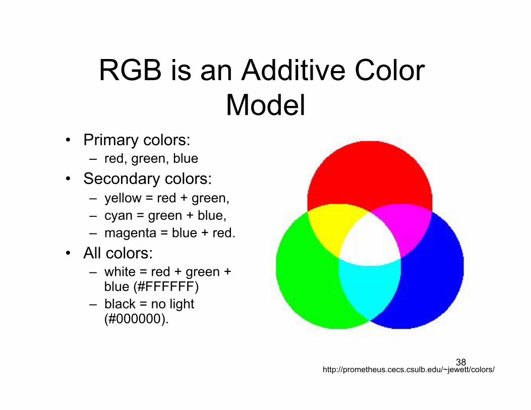
RGB is an Additive Color Model
• Primary colors: – red, green, blue
• Secondary colors: – yellow = red + green, – cyan = green + blue, – magenta = blue + red.
• All colors: – white = red + green +
blue (#FFFFFF) – black = no light
(#000000).
http://prometheus.cecs.csulb.edu/~jewett/colors/

Johns Hopkins Department of Computer ScienceCourse 600.456: Rendering Techniques, Professor: Jonathan Cohen
3 Types of retinal cones3 Types of retinal cones3 Types of retinal cones
From Foley, From Foley, vanDamvanDam, , FeinerFeiner, , and Hughes, and Hughes, Computer Computer Graphics: Principles and Graphics: Principles and Practice, 2nd edition, page Practice, 2nd edition, page 577577

Johns Hopkins Department of Computer ScienceCourse 600.456: Rendering Techniques, Professor: Jonathan Cohen
Efficient Color Computations in Computer GraphicsEfficient Color Computations in Efficient Color Computations in Computer GraphicsComputer Graphics
Represent frequency spectrum as discrete set Represent frequency spectrum as discrete set of samplesof samples•• Typically 3 samples: red, green, and blueTypically 3 samples: red, green, and blue
•• Monitors also use samples corresponding to Monitors also use samples corresponding to different phosphorsdifferent phosphors
•• Eye also has 3 samples (types of cones)Eye also has 3 samples (types of cones)
Does Does notnot imply that three samples for initial imply that three samples for initial and intermediate produce accurate and intermediate produce accurate computationscomputations
Johns Hopkins Department of Computer ScienceCourse 600.456: Rendering Techniques, Professor: Jonathan Cohen
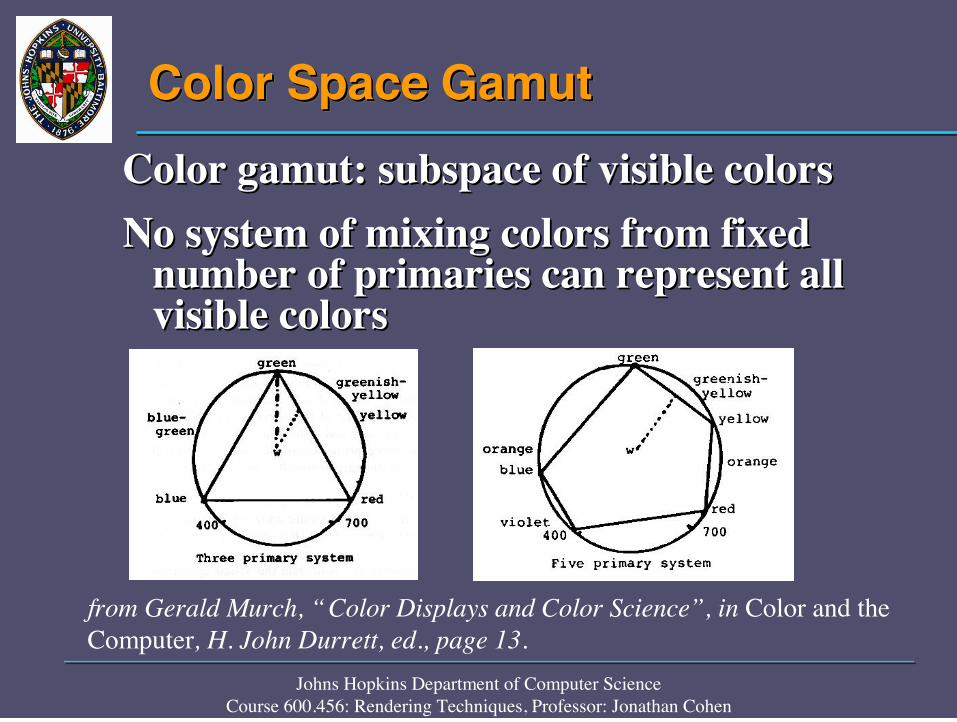
Color Space GamutColor Space GamutColor Space GamutColor gamut: subspace of visible colorsColor gamut: subspace of visible colorsNo system of mixing colors from fixed No system of mixing colors from fixed
number of primaries can represent all number of primaries can represent all visible colorsvisible colors
from Gerald Murch, “Color Displays and Color Science”, in Color and the Computer, H. John Durrett, ed., page 13.

Johns Hopkins Department of Computer ScienceCourse 600.456: Rendering Techniques, Professor: Jonathan Cohen
Color Spaces - RGB cubeColor Spaces Color Spaces -- RGB cubeRGB cube
Shortcomings:Shortcomings:•• perceptually nonperceptually non--linearlinear•• nonnon--intuitive for human specificationintuitive for human specification
From Alan Watt, 3D Computer Graphics, 2nd edition, p. 416
from Foley, vanDam, Feiner, and Hughes, Computer Graphics: Principles and Practice, plate II.4

Johns Hopkins Department of Computer ScienceCourse 600.456: Rendering Techniques, Professor: Jonathan Cohen
Color Spaces - HSV hexaconeColor Spaces Color Spaces -- HSV HSV hexaconehexaconeStill not perceptually Still not perceptually
linearlinearAxes correspond to Axes correspond to
more intuitive more intuitive perceptual qualitiesperceptual qualities•• Selection similar to Selection similar to
artist color mixingartist color mixing•• choose hue of base choose hue of base
pigment, add white, pigment, add white, add blackadd black
Derived from Derived from projections of RGB projections of RGB cubecube
From Alan Watt, 3D Computer Graphics, 2nd edition, p. 419

Johns Hopkins Department of Computer ScienceCourse 600.456: Rendering Techniques, Professor: Jonathan Cohen
CIE Color SpaceCIE Color SpaceCIE Color Space
Employs 3 artificial primaries: X, Y, ZEmploys 3 artificial primaries: X, Y, Z•• Mathematical abstractions, not physically Mathematical abstractions, not physically
realizablerealizable
•• Allow Allow supersaturationsupersaturation
Larger than visible spectrumLarger than visible spectrum
Standard for representing colors and Standard for representing colors and converting between spacesconverting between spaces

Johns Hopkins Department of Computer ScienceCourse 600.456: Rendering Techniques, Professor: Jonathan Cohen
CIE Space and Device GamutsCIE Space and Device CIE Space and Device GamutsGamuts
from Foley, vanDam, Feiner, and Hughes, Computer Graphics: Principles and Practice, plates II.1 and II.2
Chromaticity DiagramChromaticity Diagram

Johns Hopkins Department of Computer ScienceCourse 600.456: Rendering Techniques, Professor: Jonathan Cohen
Gamma CorrectionGamma CorrectionGamma Correction
Exponential function converts from deviceExponential function converts from device--independent RGB space to deviceindependent RGB space to device--dependent RGBdependent RGB•• Gamma is exponentGamma is exponent•• Every monitor is differentEvery monitor is different•• Monitor color intensities are nonMonitor color intensities are non--linear with linear with
respect to phosphor excitation levelsrespect to phosphor excitation levels

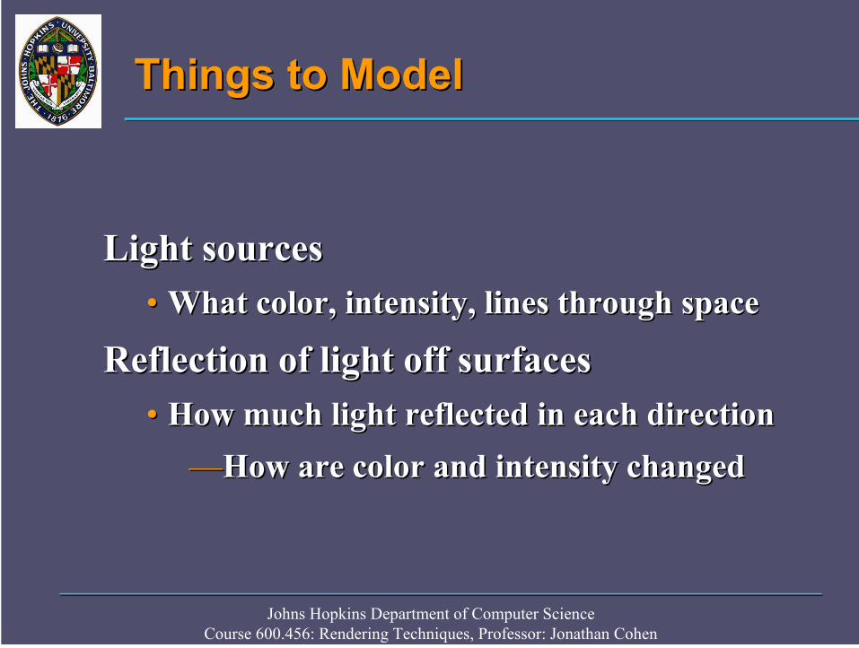
Light Models


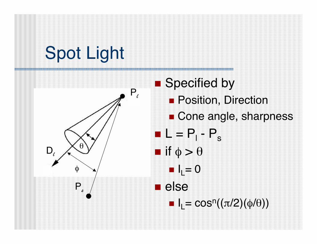
Spot Light
Dl
Pl
Ps
φ
θ
n Specified by
n Position, Direction
n Cone angle, sharpness
n L = Pl - P
s
n if φ > θn I
L= 0
n else
n IL= cosn((π/2)(φ/θ))

Shading Models

Computer Graphics Rendering Techniques: Reflection Models © KG Suffern 1991-20001 5
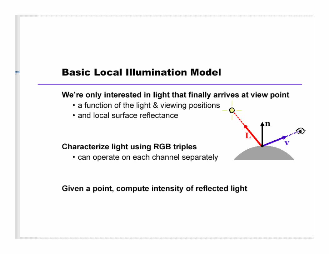
Consider the process of looking at (or photographing) a scene through awindow.
At every point on the window the light from the scene has a certainintensity I(x, y).
Intensity is a measure of the brightness of the light.
Generally there will be a mixture of light of different wavelengths ateach point on the window: I = I(x, y, !) where ! is the wavelength.
We don't discuss the wavelength dependency in these notes.
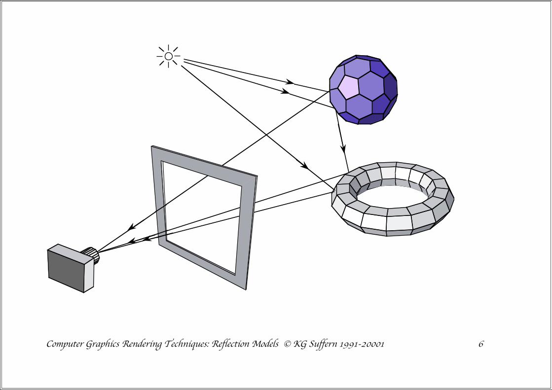
Computer Graphics Rendering Techniques: Reflection Models © KG Suffern 1991-20001 6
Computer Graphics Rendering Techniques: Reflection Models © KG Suffern 1991-20001 8
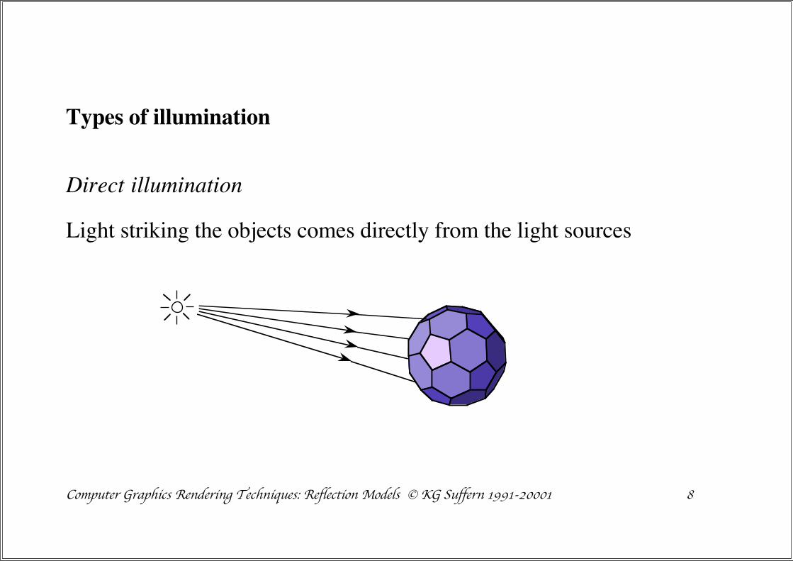
Types of illumination
Direct illumination
Light striking the objects comes directly from the light sources

Computer Graphics Rendering Techniques: Reflection Models © KG Suffern 1991-20001 9
Indirect illumination
Light striking the objects has been reflected off at least one other objectsince leaving the light source.
The light could also have been refracted through transparent objects.

Computer Graphics Rendering Techniques: Reflection Models © KG Suffern 1991-20001 10
Reflection Models
There exists a number of reflection models that model the real world tovarying degrees of realism.
In general, the more realistic a model is, the more physics andcomputation is involved.
Most reflection models incorporate direct illumination.
The indirect illumination is very expensive to calculate.
Only the most advanced rendering techniques incorporate indirectillumination.
Examples are ray tracing and radiosity.

Computer Graphics Rendering Techniques: Reflection Models © KG Suffern 1991-20001 11
Some more terminology
Direct illumination is referred to as local illumination.
Indirect illumination is referred to as global illumination.


Computer Graphics Rendering Techniques: Reflection Models © KG Suffern 1991-20001 15
Interaction of light and objects.
We must also model the way that light interacts with the surfaces ofobjects.
When light hits the surface of an object, it can be:
• Reflected
• Absorbed
• Transmitted (for transparent objects)
We see opaque objects by the light they reflect.

Computer Graphics Rendering Techniques: Reflection Models © KG Suffern 1991-20001 16
The way in which light interacts with real objects is very complicated.
The interaction depends on:
• the material properties of the object
• the wavelength of the incident light
• the angle of incidence of the light and the surface
The polarisation of the light is also involved, but rarely modelled incomputer graphics.


Computer Graphics Rendering Techniques: Reflection Models © KG Suffern 1991-20001 22
Diffuse reflection
The incident light is scattered equally in all directions
incident light
surface
This is characteristic of dull, matt surfaces such as paper, bricks, carpet,etc.


Computer Graphics Rendering Techniques: Reflection Models © KG Suffern 1991-20001 23
Specular reflection
The reflected light is concentrated around the direction of mirrorreflection, and is spread out.
incident light
surface
mirror reflectiondirection
This can be used to model shiny surfaces.


Calculating the Reflected Ray
n r = (2 ∗ (n · L) ∗ n) - Ln Derivation left for the students
n Clamp all dot products to zero. They
shouldn’t be negative, but they can be
n MAX (0, n · L)

Computer Graphics Rendering Techniques: Reflection Models © KG Suffern 1991-20001 40
"90
o#90
o
1.0 cos "
cos "2
cos "10
cos "25

Computer Graphics Rendering Techniques: Reflection Models © KG Suffern 1991-20001 46
N
RL
V
" " $diffuse
diffuse + specular
n = 10
n = 25
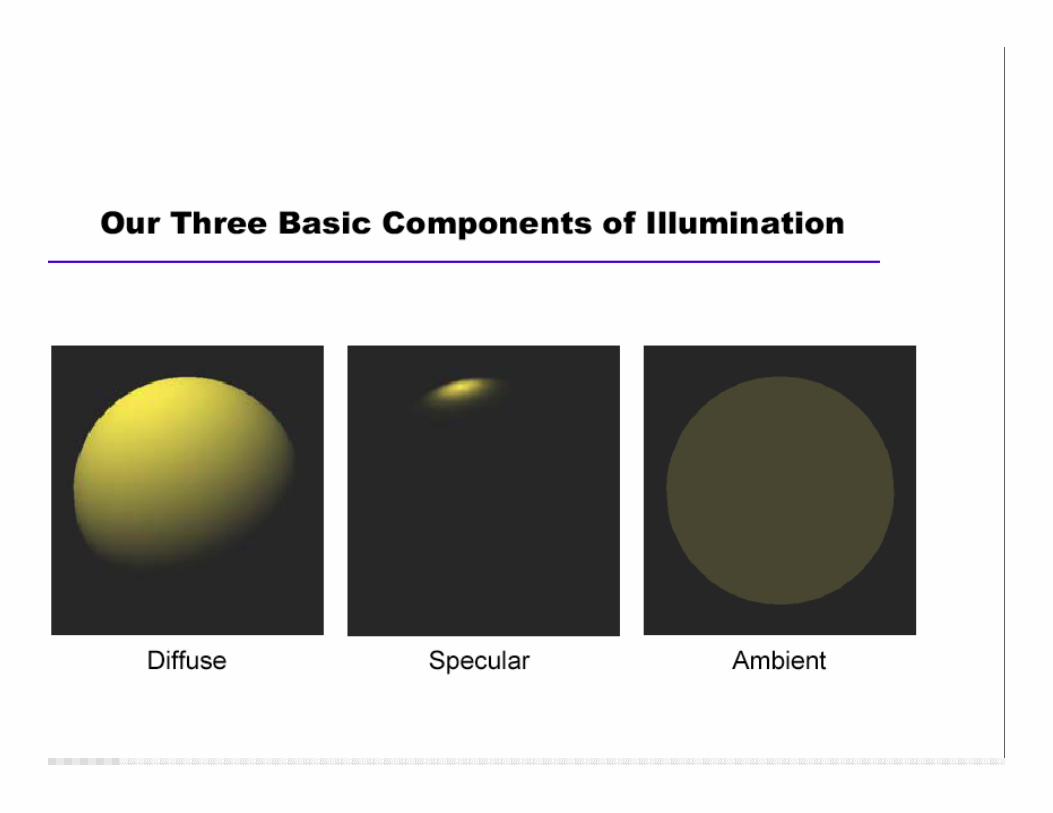
Diffuse + specular reflection


Computer Graphics Rendering Techniques: Reflection Models © KG Suffern 1991-20001 50
Originally from Larry F. Hodges, G. Drew Kessler 7
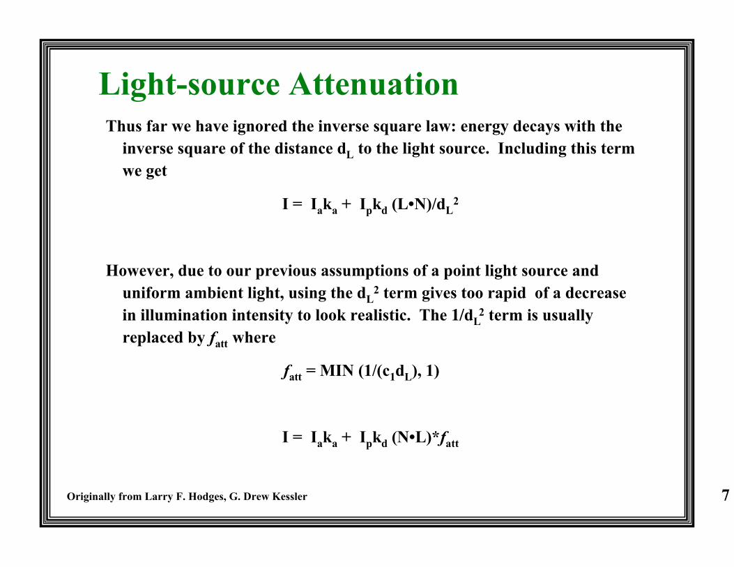
Light-source AttenuationThus far we have ignored the inverse square law: energy decays with the
inverse square of the distance dL to the light source. Including this termwe get
I = Iaka + Ipkd (L•N)/dL2
However, due to our previous assumptions of a point light source anduniform ambient light, using the dL
2 term gives too rapid of a decreasein illumination intensity to look realistic. The 1/dL
2 term is usuallyreplaced by fatt where
fatt = MIN (1/(c1dL), 1)
I = Iaka + Ipkd (N•L)*fatt


Including Surface Color
I =
for all lights {
IL kd C cos( ) + IL ks C cosn( ) }+ Ia ka C
C - RGB surface color
Could dene Cd, Cs and Ca, but youdon t have to


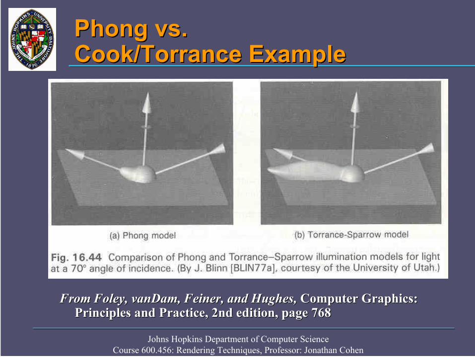
Cook and Torrance Illumination!
Distribution Functions

Cook and Torrance Illumination!
Results

Larry F. Hodges, G. Drew Kessler 11
Too Intense
With multiple light sources, it is easy to generated values of I > 1
One solution is to set the color value to be MIN(I, 1)
• An object can change color, saturating towards whiteEx. (0.1, 0.4, 0.8) + (0.5, 0.5, 0.5) = (0.6, 0.9, 1.0)
Another solution is to renormalize the intensities to vary from 0 to 1if one I > 1.
• Requires calculating all I’s before rendering anything.
• No over-saturation, but image may be too bright, and contrasts alittle off.
Image-processing on image to be rendered (with original I’s) willproduce better results, but is costly.

Calculating Normals
v -1 -1 -1v 1 -1 -1v -1 1 -1v 1 1 -1v -1 -1 1v 1 -1 1v -1 1 1v 1 1 1f 1 3 4f 1 4 2f 5 6 8f 5 8 7f 1 2 6f 1 6 5f 3 7 8f 3 8 4f 1 5 7f 1 7 3f 2 4 8f 2 8 6
vertices
triangles
n Create vector structure
(for normals) same size as
vertex structure
n For each face
n Calculate unit normal
n Add to normal structure
using vertex indicesn Normalize all the normals
n N(α,β,γ)= αNa+ βN
b+ γN
c
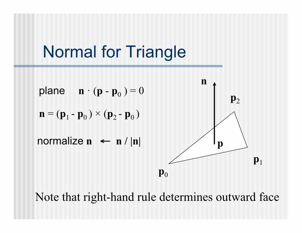
Normal for Triangle
plane n · (p - p0 ) = 0
n = (p1 - p0 ) × (p2 - p0 )
normalize n ← n / |n|
p0
p1
p2
n
p
Note that right-hand rule determines outward face
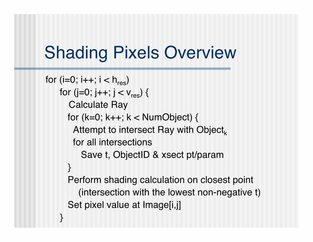
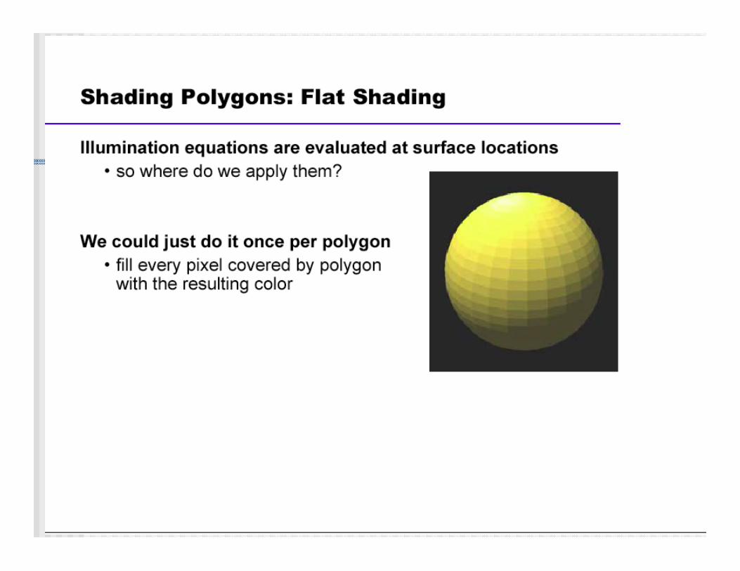
Shading Pixels Overview
for (i=0; i++; i < hres)
for (j=0; j++; j < vres) {
Calculate Ray
for (k=0; k++; k < NumObject) {
Attempt to intersect Ray with Objectk for all intersections
Save t, ObjectID & xsect pt/param
}
Perform shading calculation on closest point
(intersection with the lowest non-negative t)
Set pixel value at Image[i,j]
}

Supersample & Average Image
n hres
and vres
are even
for (i=0; i++; i < hres
/2)
for (j=0; j++; j < vres
/2) {
offset = 2 ∗ [i,j];
newImage[i,j] = (oldImage[offset] +
oldImage[offset + [0,1]] +
oldImage[offset + [1,0]] +
oldImage[offset + [1,1]])/4;
}

Wrap Up
n Discuss next week’s programming
assignment
n Add point lights with color
n Add color, shading parameters and
normals to models
n Phong shading
n Supersample image
n Discuss status/problems/issues with
this week’s programming assignment
Top Related