


Languages
Pages
Legal


Dynamic Power Factor Controller
BR 6000T
ManualVersion 2.0T E
Power Factor Controller
Blindleistungsregler
Reguladores Automáticos
de Energía Reactiva
BR 6000
Auto
Program
Manual
Service
Enter
OK
cos �
1 2 3 4 5 6 7 8 9 10 11 12
COS � =0, 98 I ND

Version 2.0T E, from march 2004

CONTENTS
Section 1 General
Section 2 Installation and connection of the controller / connection plan
2.1 Current measurement
2.2 Switching outputs
2.3 Alarm output / fault messages
Section 3 Operating modes and programming
3.1 Automatic operation / display functions
3.2 Programming
3.3 Programming lock
Section 4 Manual operation / Programming of fixed stages
Section 5 Service menu
Section 6 Expert mode
Section 7 Initial operation
Section 8 Control principle
Section 9 Troubleshooting
Section 10 Interface
Section 11 Maintenance and warranty
Section 12 Type series
Annex: Annex 1 Phase shifting
Annex 2 Technical data
Annex 3 Table of control series
Description of control-series editor
Annex 4 Default settings
Annex 5 Operating diagram (Brief programming)
- 2 -

Section1 General
The BR 6000T is distinguished by user-friendly operation based on menu-guided displays
in plain text. Its new features permit an intuitive mode of operation. Easy-to-understand
symbols and texts in the local language combine simplest operability with self-evident
displays.
The basic version contains a number of additional features:
12 switching outputs
Switching outputs with transistor
Twenty pre-programmed control series with a self-optimized intelligent control
response
for user-defined control series
Four-quadrant operation
Display of various line parameters (V, I, F, Q, P, S...)
Storage of maximum line-parameter and switching-operation values as well as
of the turn-on times of individual capacitor contactors
Manual / automatic operation
Programming of fixed stages and the option of skipping individual outputs
No-voltage turn-off
Fault detection for various statuses and interference-message output
Version in switchboard-integrated housing 144x144x55 mm
�
�
�
�
�
�
�
�
�
�
�
�
�
�
Control-series editor
Complete menu-guided operation and display
Illuminated graphic display with 2 x 16 characters
The dynamic power factor controller BR6000 T represents the consequent development
of the BR6000-series with new innovative ideas and a multitude of functions.
It has been especially designed to control thyristor modules for dynamic switching of
power capacitors for power factor correction (for example TSM or similar). By using a
very fast type of processor, it has been possible to obtain extreme short switching cycles
which allows the usage for dynamic power factor correction.
In addition to a switching time of <40 ms, the intelligent control principle provides an
extremely fast tuning of the power factor by simultaneous switching of several steps.
Several parameters that can be edited allow an optimized adjustment to different
thyristor modules.
Another novelty is the possibility of a simple coupling of two PFC-controllers with one
another (e.g. supports two transformers with coupling switch).
- 3 -

Fig. 2 BR 6000T rear view
1 2 3 4 5 6 7 8 9 10 11 12
Power Factor Controller
Blindleistungsregler
Reguladores Automaticos
de Energia Reactiva
BR 6000
Auto
Program
Manual
Service
Enter
OK
cos �
COS � =0 , 98 I ND
The controller is supplied as standard for an operating voltage of 230 VAC (L-N), a
measuring voltage of 30...300 VAC (L-N) 50/60 Hz and a measuring current of 5A or 1A
(programmable). A measuring-voltage converter is required for different operating
voltages.
Fig. 1 BR 6000-T front view
- 4 -
Operating mode
- Automatic
- Programming
- Manual operation
- Service
- Expert mode
Enter / OK
Confirm and
store values
Increase
selected
parameter
Reduce
selected
parameter
BR6000-T
meas. voltage: 30 -300V L-N 50/60Hz
supply voltage: 230V L-N 50/60Hz
Ser.No.:
power factor controller BR6000-T
L N L N k l a b P1
P2
K1
K7
K2
K8
K3
K9
K4
K10
K5
K11
K6
K12
supplyvoltage
meas.voltage
meas.current
alarm-relay
L1 (R)
L2 (S)
L3 (T)
meas.currentIm (5A/1A)
supply -voltage
Ub
meas.voltage
Umk l
P1 1 2 3 4 5 6 P2 7 8 9 10 11 12 1 2 3 4
alarmrelay
power factor -control ler BR6000T
T2
A
T2
A
PE
a b
extern 2.relay
Ub Um Im
L N L N k l
1 2 3 4
extern 2.Relay
transistor output

Section 2 Installation and connection of the controller
The BR 6000 is designed to be incorporated into the front panel of a compensation
network. It requires a switchboard section of 138 x 138 mm to DIN 43 700. The
controller is inserted from the front and is attached by means of the appended
clamps. The controller may be inserted only by qualified technicians and must be
operated in accordance with the specified safety regulations.
Before the BR 6000 is connected up, all leads and cables must be checked to ensure that
no current is flowing through them and the current converter must be short-circuited.
Care should be taken to ensure that the measuring voltage and current are in the correct
phase position. The measuring-current circuit must be wired with copper leads of
2.5mm . The connection should be set up as shown in Fig. 3. The specified safety
regulations must be observed.
The measuring voltage may lie in the range from 30 - 300 V and is connected between
L1-N (corresponds to 50 - 525 V L-L ).
The operating voltage is 230 V +/- 10% and can be connected between L1 - N in a 400-V
power line and between L - L in a 110-V power line.
2
Fig. 3: BR 6000T Connection plan
- 5 -
L1 (R)
L2 (S)
L3 (T)
N
meas.currentIm (5A/1A)
1. capacitorbranch
supply-voltage
Vb
meas.voltage
Vmk l
P1 P2
1 2 3 4 5 6 7 8 9 10 11 12
interferencemessage
relay
power factorcontrol ler BR6000
power factorcontrol ler BR6000
T2
A
T2
A
PE
a b
extern 2.relay
Ub Um Im
L N L N k l TSM-C
E.g. +24V-
+ -
Power feed Load side

2.1 Current measurement
When installing the current converter, care should be taken to ensure that the load
current flows through it. The outputs of the compensation network must be installed
behind the current converter (in the direction of current flow). If the BR 6000T is
connected up via sum-current converters, the overall conversion ratio is entered.
Current converter clamps should be grounded on one side!
kK k K
lL l L
Feed 1 Feed 2
K L K L
Measurement via sum current converter
BR6000
Current
measurement
k l
k l
2.2 Switching outputs
The switching outputs of the BR6000T are executed as transistor outputs.
The transistor outputs are used via an additional auxiliary voltage (10 - 24 VDC) for a
direct triggering of thyristor switches for the dynamic power factor correction (i.e. TSM).
See pict. 3
X2:1
X2:2
X2:6 (12)
X2:P 200mA
Further stages
�
to thyristor module
( e.g. TSM-C...)
Block circuit of the transistor output
+ -
E.g. 24VDC
- 6 -

2.3 Alarm output / fault messages
The alarm contact is closed in normal operation and opens in the event of a fault. The
relevant fault is simultaneously shown on the display in plain text (alternating with the
standard display in automatic operation). The following fault messages are displayed:
UNDER-COMPENSATED Display and relay output
OVER-COMPENSATED Display and relay output
OVERCURRENT Display and relay output
MEASURING VOLTAGE ??? Display and relay output
OVERTEMPERATURE Display and relay output
OVERVOLTAGE Display and relay output
UNDERVOLTAGE Display and relay output
UNDERCURRENT Only display (warning)
The alarm output may be checked by using artificially generated interference in the form
of "under-compensation”. This is done by interrupting the voltage supply to the power
outputs. In automatic operation - with an inductive power line - the controller then
connects all capacitor branches in. The display continues to show "Connect-in”. A fault
message appears after 10 minutes (the display shows "under-compensation / relay is
activated”).
When the operating voltage is switched on, the BR 6000 briefly displays its designation
and software version, then changes to its normal operating status (automatic operation).
The active power-line cos-phi value is always displayed in the upper line and the
currently connected capacitors are shown as symbols in the lower line (operating
display).
�
�
�
�
�
�
�
�
�
Checking the alarm output
Section 3 Operating modes and programming
21 3 4 5 6 7 8 9 10 1112
COS � =0, 98 CA P R
- 7 -
Automatic operation
Display of active power-line cos phiDisplay of 2nd active
message relay
Active capacitor
branches
Control direction
(here connected-in)
Supply display (for
4-quadrant operation)
The control direction is symbolized
by a closed arrow
The connecting-in arrow is always
located after the maximum possible
number of stages (end stop)
An open arrow indicates that the
required blocking time (discharge
time) is running before an impending
switching step
A double arrow symbolizes fast
switching of several branches
Connecting-in
Connecting-out

3.1 Automatic operation - display functions
3.2 Programming
The BR 6000T is set to automatic operation as standard. Capacitor stages are then
automatically connected in or out in order to reach the target cosine of the phase angle
(cos-phi). This happens when the required reactive power exceeds the value of the
smallest capacitor stage.
In automatic operation, various network parameters can be displayed by repeatedly
pressing the "ENTER” key:
Action Display
ENTER 1 LINE VOLTAGE in V
ENTER 2 APPARENT CURRENT in A
ENTER 3 REACTIVE POWER in kvar
ENTER 4 ACTIVE POWER in kW
ENTER 5 APPARENT POWER in kVA
ENTER 6 DIFF. kVAR TO TARGET COS
ENTER 7 FREQUENCY in Hz
ENTER 8 TEMPERATURE in °C
ENTER Software version
ENTER Return to: 1 LINE VOLTAGE
The power value specifies the total power (3-phase) assuming symmetrical load. If no
key is pressed for 60 seconds, the display automatically returns to the operating status!
Pressing the "Operating mode” key once takes the user from automatic operation to
ming mode. Parameter 1 ( I-CONVERTER) is reached by pressing "ENTER”.
The upper display always shows the parameter and the lower one the set value. The
values are changed by pressing the keys. Subsequent pressing of the "ENTER” key
stores the value and takes the user to the next parameter.
To quit programming mode in any step, press the "Operating mode” key.
:
Program
� �/
,
Automatic oper.
to display operation to programming to manual operation to value buffer to special functions
Programming Manual operation Service Expert mode
Repeated pressing of the "Operating Mode” key takes the user to the various menus in
sequence: matic operation - ming - (manual operation)-
mode and back
Auto Program Manual
Service - Expert .
- 8 -

LANGUAGE SELECTION :
1 I-CONVERTER PRIM
2 I-CONVERTER SEC
3 END STOPP
4 CONTROL SERIES
5 CONTROL PRINCIPLE
Sequential connection
INTELLIGENT loop connection
COMBINED CHOKE
6 POWER 1. STAGE
7 TARGET COS PHI
(English, German, Spanish, NL )
: This selects the primary current of the current converter. Entry
is via the / keys. (5...7500A) Save and continue with ENTER
: This sets the secondary current of the current converter
(5A or 1A possible). Selection via / . Save and continue with
ENTER
: By setting the end stopp, the number of active capacitor branches is
matched to the respective compensation network. This is done via the
/ keys. The visible symbols of the capacitors correspond to the
connected outputs. The maximum possible number of capacitor
branches is pre-set at the works (BR 6000-R12:12 branches). The
setting is confirmed and saved with the ENTER key.
: The ratio of the capacitor branch powers determines the control
series, the power of the first capacitor always being assigned the value
1. The control series required for the compensation network is again
selected via the / keys. If the required control series should
exceptionally not be present (Annex 1), the user may define a special
one (control series "E”).More on this point in the control-series editor in
Annex 1. The selected series is entered with the ENTER key, which also
takes the user to the next step.
: The control preference may be selected here:
(default setting)
See Section 8 for an explanation of the various control modes.
Selection with / keys and confirmation with ENTER leads to the
next point:
: To determine the controller's response sensitivity, the dimensions
of the network's smallest capacitor (stage 1) must be known. They are
entered in two steps in kvar. The integral kvar values (before the
comma) are initially selected via the / keys and saved with
ENTER. The positions after the comma are then selected, again via the
/ keys. Saving with the ENTER key leads to the next point.
: By setting the target cos phi, the power factor to be attained via
the PF correction is defined. It is also set via the / keys. The
range may be selected from 0.8 inductive to 0.8 capacitive. Confirming
and saving the value with ENTER leads to the next point.
� �
� �
� �
� �
� �
� �
� �
� �
�
�
�
- 9 -

- 10 -
8 MEASURING VOLTAGE
9 V - CONVERTER RATIO
: Programming the measuring voltage (L-N) of the system
(direct measurement) or the L-N voltage on the primary side of a measuring-
voltage converter. The values programmed here always refer to the voltage L-
N in the system! The voltage is selected via the / keys. Save and continue
with ENTER.
: Standard setting - NO - (direct measurement)
When a measuring-voltage converter (e.g. for center-voltage measurement)
is used, its conversion ratio should be programmed here.
Example: Voltage converter 20000V:100 V => Conversion ratio: 200
Selection via the / keys. Save and continue with ENTER.
Selection is performed via the / keys. Continue with ENTER.
� �
� �
� �
10 CONNECTING TIME
11 DISCONNECTING TIME
12 DISCHARGE TIME
: This refers to the time between connecting the capacitors to
increase the momentary network capacitance. It should be noted that in
practical operation the real connection time is affected by the discharge time
(locking time).
Setting range: 40 ms. ...1 s
Default setting: 1 sec.
Selection is performed via the / keys. Continue with ENTER
: This refers to the time between disconnecting the
capacitors to reduce the momentary network capacitance.
Setting range: 40 ms ... 1s
Default setting: 1 sec.
Selection is performed via the / keys. Continue with ENTER
: This is the time for which an individual output is blocked
between connecting and disconnecting. This blocking time has priority over
connecting and disconnecting times. It depends on the capacitor discharge rating
and thus is specified by the compensation network.
Setting range: 40 ms ...1s.
Default setting: 80 ms
� �
� �
L1 (R)
L2 (S)
L3 (T)
N
meas.currentIm (5A/1A)
operating -voltage
Vb
meas -voltage
Vm k l
BR6000 T2
A
T2
A
PE
Vb Vm Im
L N L N k l
Connection of the BR6000 via measuring -voltage converter ( L-N )

- 11 -
13 ALARM TEMP
alarm relay
14 MESSAGE RELAY
:
The temperature inside the BR 6000 is measured and converted to the internal
temperature of the switching cabinet. This value can be shown on the display.
The alarm temperature programmed here is the temperature at which the
capacitor stages are disconnected in steps. The controller’s
responds after ten minutes. At the same time the display shows the cause of the
alarm (over-temperature). If the temperature drops again, the required
branches are automatically re-connected in steps.
:
Controller 1 Controller 2
The message relay can be programmed for of the following options as required:
"Fan”: Relay switches the external cabinet fan.
(Default) The switching threshold can be programmed under 15.
Display: "R”
"Supply": Message when active power is supplied. Display: "R”
"Undercurrent”: This message appears whenever the measuring current is not
reached. Display: "R” The signal is generated when the value
drops below the response sensitivity of the controller.
"External”: The relay switches if an external input signal (230 VAC) is sent to
the "cos-phi2 /external” input. This function may be used to directly
compensate a larger load, for example - the required 40-second
reconnection delay is already integrated.
Display: Capacitor symbol at the top right of the first line.
When this function is selected, the input cannot be used for the
signal 'target cos phi2' and the output cannot be used for the fan.
"Remote control R1”: Coupling of two controllers via remote control input,
R1= Controller is configured as controller 1 (master)
"Remote control R2”: Coupling of two controllers via remote control input,
R2= Controller is configured as controller 2 (slave).
one
By coupling a BR6000-R with a dynamic controller (BR6000-T) a mixed dynamic system
can be designed that implements economically the advantages of a dynamic fast
network. When coupling, "Controller1" (as master) and "Controller2" (as slave) has to be
programmed in this menu point.For coupling the controllers of both systems have to be
connected as follows:
P1 1 2 3 4 5 6 P2 7 8 9 10 11 12 1 2 3 4 P1 1 2 3 4 5 6 P2 7 8 9 10 11 12 1 2 3 4
capacitor-contactors 1-6
capacitor-contactors 1-6
capacitor-contactors 1-6
alarm-relay
alarm-relay
alarm-relay
capacitor-contactors 7-12
capacitor-contactors 7-12
capacitor-contactors 7-12
BR6000-R12 (stat ic) BR6000-T12 (dynamic)
a b a b
external 2.relayexternal 2.relay external 2.relay
Ub UbUm UmIm Im
L N L N k l L N L N k l
230VAC

15 and 16 PARAMETERS for message-relay option:
Fan option
Target cos phi2
2
17 DELAY-TIME OF ERROR-MESSAGES
CONTRAST
BASIC SETTING:
network
Depending on the programming of the message relay, the following parameters may be
selected here:
: Input of the switching threshold for the fan (30-70°C)
: Input of the second target cos phi as described under point 7,
e.g. tariff conversion.
Input signal 230 VAC at input cos phi => target cos phi 2.
At the active input, the display shows: cos …
These Delay time you can change between 0 and 240 seconds.
The display contrast can be changed with this menu point. The contrast depends
to a certain degree on the viewpoint of the observer, i.e. on the insertion height
of the equipment in the switching cabinet. The / keys can be used to set an
optimal contrast. The contrast changes after a slight delay.
Selection YES / NO
When the selection is made with YES and confirmed with ENTER, all parameters are
reset to the basic setting made by the manufacturer. (Optimal network
values when the controller was supplied with a complete network). If the controller
is supplied from the works, this point corresponds to the default setting.
CAUTION: All user settings are lost!
Programming is now completed. The controller has returned to point 1 of the
programming menu.
The BR 6000T is equipped with a programming lock to ensure protection from
unauthorized or inadvertent changes to the system parameters. The lock can be
activated in expert mode. If the lock is active, all parameters can be checked but not
changed.
�
�
�
� �
3.3 Programming lock
Only active
when option 'Fan' is selected (temperature input as described under point 13)
- 12 -

Section 4 Manual operation (initial operation, maintenance, service)
Programming of fixed stages
in the set
control series and switching time -
AUTO
FIXED
OFF
In manual operation, capacitor branches can be connected/disconnected
irrespective of prevailing power-line conditions.
Connections are made by pressing the key. Pressing of leads to the disconnection
of stages.
The active operating status and active power factor are always shown on the display (self-
explanatory).
Pressing ENTER takes the user to the menu point "Programming of fixed stages”. In the
normal case, all stages are programmed for automatic operation (default setting).
In special cases, all controller outputs (C1 - C12) may be permanently defined in
succession (continued switching via ENTER) for the following statuses:
: Automatic (normal) operation
The relevant output is marked by a capacitor symbol.
: The output is continuously connected, e.g. for ongoing basic correction. The
output is marked by an underlined capacitor symbol.
: The output is continuously disconnected - e.g. for temporarily disconnecting a
defective capacitor. The capacitor symbol for this output is faded out. Underlining
appears.
The active stage is marked by blinking. The required status is set via . By pressing
ENTER, the user saves this step and moves to the next stage.
The programmed statuses for the outputs also remain visible on the display in automatic
operation.
After the required settings have been made, pressing the "Operating Mode” key takes the
user to the next menu ("Service”) or further to "Automatic Operation”.
� �
� �/
�
�
�
Currently selected stage blinks
Setting of fixed stages
1 2 3 4 5 6 7 8 9 10 11 12
C1: AUT O
1 2 3 4 5 6 7 8 9 10 11 12
Manual operation
ST OPP C 0, 98 CAP
- 13 -
- 14 -
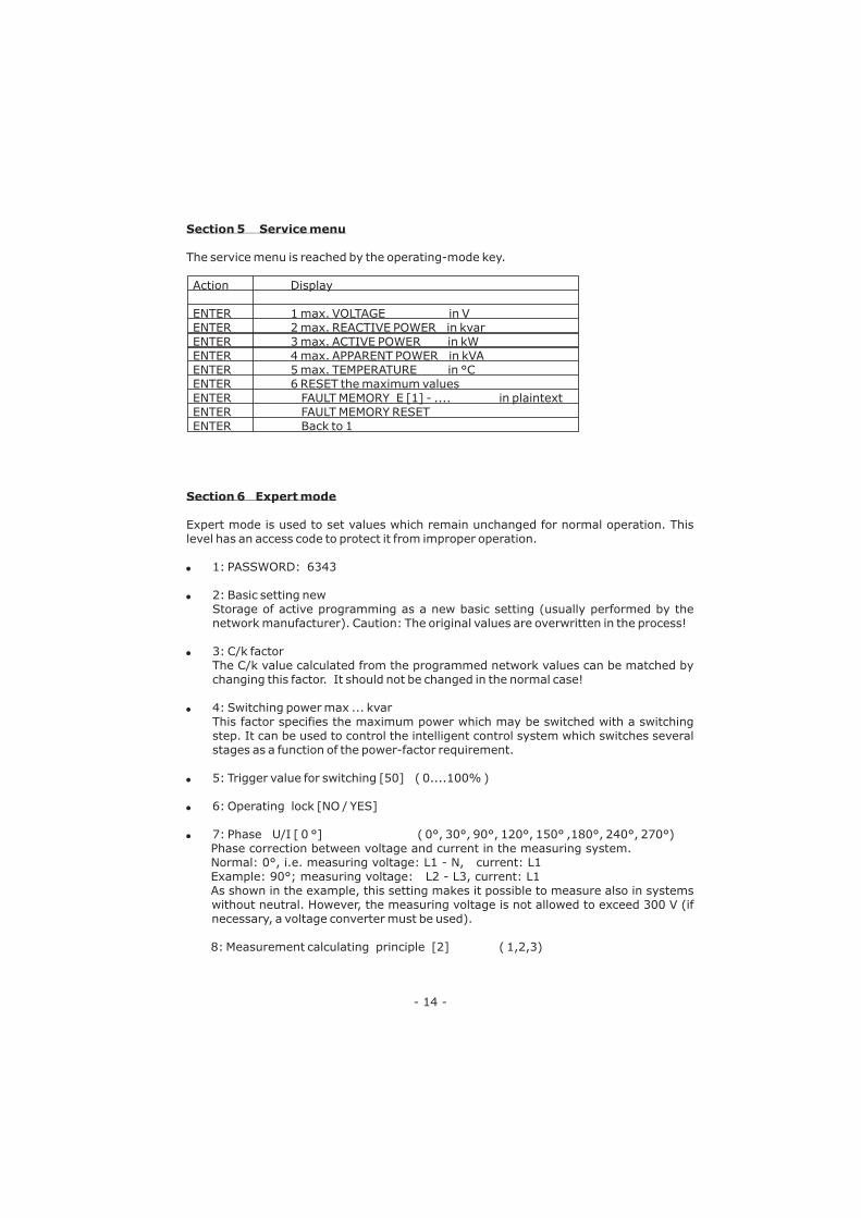
Section 5 Service menu
Section 6 Expert mode
The service menu is reached by the operating-mode key.
Action Display
ENTER 1 max. VOLTAGE in V
ENTER 2 max. REACTIVE POWER in kvar
ENTER 3 max. ACTIVE POWER in kW
ENTER 4 max. APPARENT POWER in kVA
ENTER 5 max. TEMPERATURE in °C
ENTER 6 RESET the maximum values
Expert mode is used to set values which remain unchanged for normal operation. This
level has an access code to protect it from improper operation.
1: PASSWORD: 6343
2: Basic setting new
Storage of active programming as a new basic setting (usually performed by the
network manufacturer). Caution: The original values are overwritten in the process!
3: C/k factor
The C/k value calculated from the programmed network values can be matched by
changing this factor. It should not be changed in the normal case!
4: Switching power max ... kvar
This factor specifies the maximum power which may be switched with a switching
step. It can be used to control the intelligent control system which switches several
stages as a function of the power-factor requirement.
5: Trigger value for switching [50] ( 0....100% )
6:
ENTER
Operating lock [NO / YES]
7:
�
�
�
�
�
�
�
FAULT MEMORY E [1] - .... in plaintext
ENTER FAULT MEMORY RESET
ENTER Back to 1
Phase U/I [ 0 °] ( 0°, 30°, 90°, 120°, 150° ,180°, 240°, 270°)
Phase correction between voltage and current in the measuring system.
Normal: 0°, i.e. measuring voltage: L1 - N, current: L1
Example: 90°; measuring voltage: L2 - L3, current: L1
As shown in the example, this setting makes it possible to measure also in systems
without neutral. However, the measuring voltage is not allowed to exceed 300 V (if
necessary, a voltage converter must be used).
8: Measurement calculating principle [2] ( 1,2,3)

- 15 -
Section 7 Initial operation
Section 8 Control principle
The controller must have been installed before being set up and operated.
All network-specific parameters are fully programmed as described in Section 3.2
(Programming) by being entered in sequence and stored. The controller is then set to
automatic operation with the operating mode key. It is now ready for operation.
The control response of the BR 6000T can be selected in programming mode. In principle,
the controller has 3 different control modes:
In sequential connection, the required capacitor stages are successively connected
and disconnected in stages (last in - first out). The ranking of each step always
corresponds to the power of the smallest stage.
: Exact definition of the next capacitor to be connected in each case
The maximum
dimensions of the simultaneously switching branches can be changed in expert
mode. (Prog. point 7). If the value of the smallest stage is pre-selected, the
conventional sequential connection is obtained.
The intelligent control principle combines the advantages of the network-sparing
loop connection (first in - first out) with a much faster settling time, even for large
load skips, and reaches this goal with the fewest possible switching operations of the
capacitor stages. The optimized time response is achieved by the simultaneous
switching of several or larger capacitor groups as a function of the missing power
factor in the power line. Both the number of real switching frequencies of the
capacitors as well as the turn-on times of the branches are considered.
: Reaches the target cos phi in a fast-optimized settling time with a low
switching frequency of the capacitors.
Within a combined de-tuned application, 2 adjoining equal steps are switched with
just one joint choke. This pairwise de-tuning requires an appropriate closed control
series (i.e. 1:1:1:1..., 1:1:2:2..., 1:1:2:2:4:4... or similar)
The condition for the switching behavior is defined in such a way that the number of
activated odd steps is always greater than or equal to the number of activated even
steps. The controller complies with the requirements of the control regime while
largely conforming to the intelligent switching behavior.
1. Sequential connection
Advantage
In order to shorten the settling time, the BR 6000T switches several stages
simultaneously for a large power-factor requirement.
2. Intelligent loop connection (default setting )
Advantage
3. Combined de-tuning (special case for combined de-tuned banks)

- 16 -
Fault
At target cos phi=1 and inductive load,
switch-off or connection in the corrected
line Supply / Drawing display switched
round
Wrong line cos phi is displayed
Display:"UNDER CURRENT”
Display: "OVERCURRENT”
Alarm relay: after 10 min.
Display: "UNDERCOMPENSATED”
Alarm relay: after 10 min.
Display: "OVERCOMPENSATED”
Alarm relay: after 10 min.
Display: "MEASUREMENT VOLTAGE ???”
Alarm relay: after 10 min.
Display: "OVERTEMPERATURE”
Alarm relay: after 10 min.
Stages are disconnected for an inductive
line or connected for a capacitive line
The controller does not connect all
stages, or cos phi does not change at the
last stages
In automatic operation, individual stages
are not connected or disconnected:
In strongly asymmetrically loaded lines,
differences may occur between control
r e s p o n s e a n d p o w e r - f a c t o r
measurement, as the power factor is
measured in single phase.
No operating voltage
Check / Solution
Check terminals of the measuring voltage and
current (l and k)!
Check phase position
See above
Current in measuring range?
Line interruption?
Wrong current-converter factor?
Current controller short-circuited?
Check current-converter ratio
Go through measuring current range
Check connection and phase position!
All stages connected - target cos phi not
reached: compensation network sufficiently
dimensioned?
Check connection and phase position!
Capacit ive l ine, although all stages
disconnected
No measurement voltage!
Network temperature too high: Outputs are
switched off in stages irrespective of power-line
conditions
If a target cos phi is set which deviates from 1
despite an inductive line load, the display <-
(disconnect stages) may light up. The arrows
indicate the control direction and not the line
conditions.
Check END STOPP!
Check whether individual stages are
programmed as fixed stages or OFF in the
"Manual operation / Fixed stages” menu!
Line measurements allow the most favorable
phase for measuring the power factor to be
determined. The current converter is set
accordingly for the measuring current.
Note: No display, alarm relay is closed
Section 9 Troubleshooting

- 17 -
Section 10 Interface *
Section 11 Maintenance and warranty
Section 12 Type series and accessories
The BR 6000 T is equipped without an Interface Rs232 / 485.
An option is another interface for a power-monitoring of the complete PFC-system.
The BR 6000T should need no maintenance if the operating conditions are observed.
However, it is recommended that a functional check of the controller be performed in
conjunction with the regular checking of the compensation network. In the event of any
interventions in the controller during the warranty period, all warranty claims lapse.
BR6000-T12 12 transistor outputs, 1 interference-message output
2nd message relay
BR6000-T12/E 12 transistor outputs, 1 interference-message output
2nd message relay, Input power monitoring PFC-system
Adapter Adapter for Power Factor Controller Br6000
BR6000-999 (Connection in grids without neutral conductor)
Annex 1:
Programming of phase-correction between voltage and current in the meas. System
Example 1:
Meas.current: L1
Meas. Voltage L3-L2
( V-converter
must be used)
Phase U/I [ 90°]
Meas. Current meas.voltage volt.converter Phase correction
Example : L1 L1 - L2 yes 30°
Example : L1 L3 - N no 120°
Example : L1 L3 - L1 yes 150°
Example : L1 ( k<->l ) L1 - N no 180°
Example: L1 L2 - N no 240°
Example: L1 ( k<->l ) L2 - L3 yes 270°
L1 (R)
L2 (S)
L3 (T)
N
Meas.currentsupply-voltage
Vb
meas. -voltageL2-L3 k l
BR6000 T2
A
T2
A
PE
Ub Um Im
L N L N k l

- 18 -
Annex 2: Technical data
Type series
Outputs
Switching power of transistor output
Number of active outputs
Operation and display
Number of control series
User-defined control series
Control principle
Operating voltage
Measuring voltage
Measuring current
Power drawn
Sensitivity
Target cos phi
Switching time
Discharge time
Fixed stages / skipped stages
Alarm relay
No-voltage triggering
Display of power-line parameters
Storage of maximum values
Temperature measurement range
Housing
Ground
Operating ambient temperature
Protection type to DIN 40 050
Coupling 2 controllers
(working as master / slave)
BR 6000..T
12
24VDC, 20mA
Programmable
Illuminated graphic display 2 x 16 characters
with convenient operating level
20
1
Selectable
Sequential connection or
self-optimized switching response
Four-quadrant operation
230 VAC, 50 / 60Hz
30...300 VAC (L-N), 50 / 60Hz
X : 5 / 1A selectable
< 5 VA
40 mA / 10 mA
0.8 inductive to 0.8 capacitive adjustable
Selectable from 40ms ... 1 sec.
Selectable from 40ms ... 1 sec.
Programmable
Standard
Standard
Voltage, apparent current, frequency, power
factor, active power, apparent power, missing
kvar, temperature
Voltage, power factor, active power, apparent
power, temperature
0 - 100°C
Switchboard-integrated housing
DIN 43 700, 144 x 144 x 53 mm
1 kg
-10 to +60°C
Front: IP 54, Rear: IP 20
possible

- 19 -
Annex 3: Table of control series
No.
1
2
3
4
5
6
7
8
9
10
11
12
13
14
15
16
17
18
19
20
"E"
Control series
1 : 1 : 1 : 1 : 1 : 1 : 1 : 1 : 1 : 1 : 1 : 1
1 : 2 : 2 : 2 : 2 : 2 : 2 : 2 : 2 : 2 : 2 : 2
1 : 2 : 3 : 3 : 3 : 3 : 3 : 3 : 3 : 3 : 3 : 3
1 : 2 : 3 : 4 : 4 : 4 : 4 : 4 : 4 : 4 : 4 : 4
1 : 2 : 4 : 4 : 4 : 4 : 4 : 4 : 4 : 4 : 4 : 4
1 : 2 : 3 : 6 : 6 : 6 : 6 : 6 : 6 : 6 : 6 : 6
1 : 2 : 4 : 8 : 8 : 8 : 8 : 8 : 8 : 8 : 8 : 8
1 : 1 : 1 : 1 : 2 : 2 : 2 : 2 : 2 : 2 : 2 : 2
1 : 1 : 1 : 1 : 1 : 6 : 6 : 6 : 6 : 6 : 6 : 6
1 : 1 : 2 : 2 : 2 : 2 : 2 : 2 : 2 : 2 : 2 : 2
1 : 1 : 2 : 2 : 2 : 4 : 4 : 4 : 4 : 4 : 4 : 4
1 : 1 : 2 : 2 : 4 : 4 : 4 : 4 : 4 : 4 : 4 : 4
1 : 1 : 1 : 2 : 2 : 2 : 2 : 2 : 2 : 2 : 2 : 2
1 : 1 : 2 : 3 : 3 : 3 : 3 : 3 : 3 : 3 : 3 : 3
1 : 1 : 2 : 4 : 4 : 4 : 4 : 4 : 4 : 4 : 4 : 4
1 : 1 : 2 : 4 : 8 : 8 : 8 : 8 : 8 : 8 : 8 : 8
1 : 2 : 2 : 3 : 3 : 3 : 3 : 3 : 3 : 3 : 3 : 3
1 : 2 : 3 : 4 : 4 : 8 : 8 : 8 : 8 : 8 : 8 : 8
1 : 2 : 2 : 4 : 4 : 4 : 4 : 4 : 4 : 4 : 4 : 4
1 : 2 : 2 : 2 : 4 : 4 : 4 : 4 : 4 : 4 : 4 : 4
Control-series editor
Loop connection
Possible
Possible
Possible
Possible
Possible
Possible
Possible
Possible
Possible
Possible
Possible
Possible
Possible
Possible
Possible
Possible
Possible
Possible
Possible
Possible
Possible
Control-series editor
The control-series editor allows the user to simply define his/her own control series if the
required control series is not available for any reason.
The last control series - Control Series E - is selected by pressing the "Programming” key
(point 4: Control series) and confirmed with ENTER. This leads to the insertion of an
additional menu point in the main menu -> the control-series editor. It may be reached
via the "Operating Mode” key.
In the control-series editor, all stages can be set in succession to the desired value with
the selection keys . The next stage in each case is reached by pressing ENTER. An
intelligent pre-selection of the stages is integrated, so that only "meaningful”
control series can be generated. The maximum number of stages can be limited by a
programmed END STOPP < 12.
The user may quit the editor with the "Operating Mode” key.
� �/
ProgrammingAutomatic Control serieseditor
Manual operation Service Expert mode

Annex 4: Default settings
No.
1
2
3
4
5
6
7
8
9
10
11
12
13
14
15
16
Parameter
I CONVERTER prim.
I CONVERTER sec.
END STOPP
CONTROL SERIES
CONTROL PRINCIPLE
POWER 1. STAGE
TARGET COS-PHI
MEASURING VOLTAGE
V- CONVERTER RATIO
SWITCH IN TIME
SWITH OFF TIME
DISCHARGE TIME
ALARM TEMP.
MESSAGE RELAY
FAN TEMP.
TARGET COS PHI 2
CONTRAST
Capacitor stages
Password
C/k constant
Max. simultaneous
switching power
Phase U/I
Operating lock
Default setting
1000 A
5 A
12 ( 6 )
1
INTELLIGENT
25.00 kvar
0.98 IND
230 V L-N
- NO -
1
1 s
80 ms
55°C
FAN
30°C
0,95 IND
7
AUTO
6343
0.66
4 x smallest stage
power
0°
NO
Programmed values of this
network (to be entered by
network manufacturer or
operator)
Cannot be changed
Note: The following values for the default settings apply only if the controller is supplied
directly from the works. Otherwise, these values are replaced by the basic settings made
by the manufacturer of the compensation network (optimal values for the relevant
network).
- 20 -

PROGRAMMINGCONTROL SERIES
EDITOR
1 LINE VOLTAGE
400,0 V
2 APPARENT CURRENT
88,88 A
3 REACTIVE POWER
88,88 kvar
UNDERCOMPENSATED.
4 ACTIVE POWER
88,88 KW
OVER-COMPENSATED
5 APPARENT POWER
88,88 kVA
6 DIFF REACT POWER
88,88 kvar
7 FREQUENCY
50,0 Hz
UNDERCURRENT
KVAR-RATIO C 2
1 2 2 2 2 2 2 2 2 2 21
KVAR-RATIO C 3
1 2 2 2 2 2 2 2 2 2 21
KVAR-RATIO C 4
1 2 2 2 2 2 2 2 2 2 21
KVAR-RATIO C 5
1 2 2 2 2 2 2 2 2 2 21
KVAR-RATIO C 12
1 2 2 2 2 2 2 2 2 2 21
1 I-CT PRIMARY
[ 1000 ] A / X
LANGUAGE SELECT
[ENGLISH]
2 I-CT SECONDARY
8 MEAS.VOLTAGE
[ 230 ] V L -N
9 V - CT RATIO
- NO -
10 SWITCHING IN TIME
[ 1s ]
11 SWITCHING OFF TIME
[ 1s ]
12 DISCHARGE TIME
[80] ms
13 ALARM TEMP
[55] °C
14 MESSAGE RELAY
[FAN]
15 FAN TEMP.
[55]°C
8 TEMPERATURE *
40,0°C
OVERCURRENT
SOFTWARE
VERSION 2.0 / E
MEAS. VOLTAGE ???
UNDERVOLTAGE
OVERTEMPERATURE*
85 °C
Changing
of values
by buttons:After 60 sec. without pressing
any button, automatic change
to auto-mode
In case of error
alternating display between
error and cos Phi
4 CONTROL SERIES
1 1 1 1 1 1 1 1 1 1 1 1
5 CONTROL MODE
INTELLIGENT
7 TARGET COS PHI
( 0,8 IND ... 0,8 CAP)
6 POWER 1.STAGE
[ 25 ], 00 kvar
3 END STOPP
AUTO MODE
RETURN TO 1
RETURN TO 1
only available if control
serie “E” is selected
up to capacitor 6 / 12
21 3 4 5 6 7 8 9 10 1112
C OS � =0 , 98 C AP
1000 / [5] A
16 TARGET COS PHI 2
[ 0,95 ] ind
CONTRAST
- 7 -
17 ERROR DELAY TIME
[20] sec
BASIC SETTINGS
RESET - NO -
BACK TO 1

Annex 5
Operating diagram (Brief programming)
Power Factor Controller BR6000T
MANUAL MODE SERVICE EXPERT MODE
MANU C 0,98 CAP 1 max VOLTAGE
400,0 V
1 PASSWORD ????
[ **** ]
2 max REACTIVE POWER
88,88 kvar
3 max ACTIVE POWER
88,88 kW
4 max APPARENT PWR
88,88 kVA
5 max TEMPERATURE*
70,0 °C
6 MAXIMUM VALUE
RESET - NO -
2 BASIC SETTINGS
NEW ? - NO -
C1 : AUTO (FIXED / OFF )
C2 : AUTO (FIXED / OFF )
C3 : AUTO (FIXED / OFF )
C4 : AUTO (FIXED / OFF )
C5 : AUTO (FIXED / OFF )
C6 : AUTO (FIXED / OFF )
C7 : AUTO (FIXED / OFF )
C8 : AUTO (FIXED / OFF )
C9 : AUTO (FIXED / OFF )
C10 : AUTO (FIXED / OFF )
C11 : AUTO (FIXED / OFF )
C12 : AUTO (FIXED / OFF )
3 C/k FACTOR
[ 0,66 ]
4 SWITCH. POWER MAX
[ ... ] kvar
5 SWITCH. TRIGGER
[50] %
6 PROGRAM LOCK
[ NO ]
7 PHASE U / I
[ 0 ] °
8 MEAS.CALC.PRINCIP
[ 2 ]
Selecting of
capacitors C1-C12
BACK TO 1
BACK TO 2
BACK TO 1
Top Related