


![Automobile Injury Compensation Appeal Commission · debilitating physical impairment, he nonetheless strove to make a life for himself and to lessen ... your duties as [text deleted]](https://static.fdocuments.in/doc/165x107/5f72d54bb33ab63e27588658/automobile-injury-compensation-appeal-commission-debilitating-physical-impairment.jpg)


Languages
Pages
Legal


Correction of diplopia in adults withvirtual environments
Edward James
Supervised by
Anthony Steed
Submitted April 28, 2016
This report is submitted as part requirement for the
MEng Degree in Computer Science
at
University College London.
It is substantially the result of my own work except where explicitly indicated in
the text. The report may be freely copied and distributed provided the source is
explicitly acknowledged.
Abstract
Diplopia (double vision) is a debilitating visual impairment, and little has been done
in the field of computer graphics to attempt to correct this. This report describes
a novel technique for presenting stereoscopic images to sufferers of diplopia - and
other visual impairments - granting stereo fusion by applying the correct orientation
of the stereo half-image view plane of the afflicted eye.
An investigation into several different techniques for correcting diplopia was
taken, resulting in the creation of two Unity 3D based applications: one for a
Head Mounted Display (HMD) and one for a Cave Automatic Virtual Environment
(CAVE), the latter of which incorporated eye tracking to automatically adjust the
image presented to the user.
Described is a proof of concept computer system that successfully emulates
the process to prism shifting glasses through the use of a CAVE and eye tracker
to deliver a perspective correct stereo half-image to the misaligned eye of the user,
allowing singular vision to sufferers of diplopia. Also outlined is how this concept
can be used in an augmented reality correctional head set, giving corrected vision
to the disabled in the real world.
Acknowledgements
• William & Vivienne James, for supporting me through the writing process
• Anthony Steed & David Swapp, for putting up with me and helping me chase
my dream
• Jennifer Steiert, for proofing this report
• Emilie Brotherhood & Jason Drummond, for letting me fiddle around with
the EyeLink
• Brain & the SR support team, for helping me get the blasted thing working
properly
• Kevin Tchaka, for helping around the labs
• Alfie Casson, for hyping this project up and rekindling my interest in it
• The Hirby’s Dreamland crew, for being there I guess
• Pitri Patel & Specsavers Tottenham Court Road, for performing my eye tests
and explaining my condition
Contents
1 Introduction 10
1.1 Outline . . . . . . . . . . . . . . . . . . . . . . . . . . . . . . . . 10
1.2 Aims & Goals . . . . . . . . . . . . . . . . . . . . . . . . . . . . . 11
1.3 Overview . . . . . . . . . . . . . . . . . . . . . . . . . . . . . . . 12
1.4 Algorithm Overview . . . . . . . . . . . . . . . . . . . . . . . . . 12
1.5 Report Structure . . . . . . . . . . . . . . . . . . . . . . . . . . . . 13
2 Context 14
2.1 Background . . . . . . . . . . . . . . . . . . . . . . . . . . . . . . 14
2.2 Motivation . . . . . . . . . . . . . . . . . . . . . . . . . . . . . . . 16
2.3 Research Carried Out . . . . . . . . . . . . . . . . . . . . . . . . . 16
2.4 Related Work . . . . . . . . . . . . . . . . . . . . . . . . . . . . . 17
2.5 Frameworks Used . . . . . . . . . . . . . . . . . . . . . . . . . . . 18
3 Depth 20
3.1 Investigation Into Depth . . . . . . . . . . . . . . . . . . . . . . . 20
4 Initial Correction Prototypes 23
4.1 Camera Translation . . . . . . . . . . . . . . . . . . . . . . . . . . 23
4.2 Camera Rotation . . . . . . . . . . . . . . . . . . . . . . . . . . . 24
4.3 Render Translation . . . . . . . . . . . . . . . . . . . . . . . . . . 24
5 Final Design & Implementation 28
5.1 View Plane Rotation . . . . . . . . . . . . . . . . . . . . . . . . . 28
Contents 5
5.2 Overview . . . . . . . . . . . . . . . . . . . . . . . . . . . . . . . 30
5.3 Detail . . . . . . . . . . . . . . . . . . . . . . . . . . . . . . . . . 31
5.3.1 View-Cube Rotation . . . . . . . . . . . . . . . . . . . . . 31
5.3.2 Calculation of Correct Orientation . . . . . . . . . . . . . . 33
5.3.3 Eye Tracking . . . . . . . . . . . . . . . . . . . . . . . . . 34
5.3.4 Drift Correction . . . . . . . . . . . . . . . . . . . . . . . . 37
6 Testing & Analysis 40
6.1 Tests . . . . . . . . . . . . . . . . . . . . . . . . . . . . . . . . . . 40
6.2 Analysis . . . . . . . . . . . . . . . . . . . . . . . . . . . . . . . . 40
7 Conclusion 43
7.1 Summary . . . . . . . . . . . . . . . . . . . . . . . . . . . . . . . 43
7.2 Critique . . . . . . . . . . . . . . . . . . . . . . . . . . . . . . . . 44
7.3 Future work . . . . . . . . . . . . . . . . . . . . . . . . . . . . . . 46
7.4 Final Thoughts . . . . . . . . . . . . . . . . . . . . . . . . . . . . 47
Appendices 51
A System Manual 51
A.1 Overview . . . . . . . . . . . . . . . . . . . . . . . . . . . . . . . 51
A.2 CAVE System . . . . . . . . . . . . . . . . . . . . . . . . . . . . . 51
A.2.1 Technical Specification . . . . . . . . . . . . . . . . . . . . 52
A.2.2 Set Up . . . . . . . . . . . . . . . . . . . . . . . . . . . . 53
A.2.3 Run Order . . . . . . . . . . . . . . . . . . . . . . . . . . . 54
A.3 HMD portion . . . . . . . . . . . . . . . . . . . . . . . . . . . . . 55
A.3.1 Technical Specifications . . . . . . . . . . . . . . . . . . . 55
A.3.2 Set Up . . . . . . . . . . . . . . . . . . . . . . . . . . . . 55
B User Manual 57
B.1 CAVE . . . . . . . . . . . . . . . . . . . . . . . . . . . . . . . . . 57
B.1.1 Experiment Configuration . . . . . . . . . . . . . . . . . . 57
B.2 HMD . . . . . . . . . . . . . . . . . . . . . . . . . . . . . . . . . 60
Contents 6
B.2.1 Experiment Configuration . . . . . . . . . . . . . . . . . . 60
B.2.2 Set Up . . . . . . . . . . . . . . . . . . . . . . . . . . . . 60
B.2.3 Controls . . . . . . . . . . . . . . . . . . . . . . . . . . . . 60
C Supporting documentation 63
C.1 Blog . . . . . . . . . . . . . . . . . . . . . . . . . . . . . . . . . . 63
C.2 Video Links . . . . . . . . . . . . . . . . . . . . . . . . . . . . . . 63
C.3 Miscellaneous . . . . . . . . . . . . . . . . . . . . . . . . . . . . . 64
D Evaluation Data & Results 65
E Project Plan & Interim Report 69
E.1 Project Plan . . . . . . . . . . . . . . . . . . . . . . . . . . . . . . 69
E.1.1 Aims and Objectives . . . . . . . . . . . . . . . . . . . . . 69
E.1.2 Deliverables . . . . . . . . . . . . . . . . . . . . . . . . . 70
E.1.3 Work Plan . . . . . . . . . . . . . . . . . . . . . . . . . . . 70
E.2 Interim Report . . . . . . . . . . . . . . . . . . . . . . . . . . . . . 72
E.2.1 Progress made to date . . . . . . . . . . . . . . . . . . . . 72
E.2.2 Remaining work to be done . . . . . . . . . . . . . . . . . 73
F Code Listing 74
F.1 CAVE Unity project code . . . . . . . . . . . . . . . . . . . . . . . 74
F.2 Eye tracker data forwarding code . . . . . . . . . . . . . . . . . . . 96
F.3 HMD Unity project code . . . . . . . . . . . . . . . . . . . . . . . 98
F.4 Data analysis code . . . . . . . . . . . . . . . . . . . . . . . . . . 104

List of Figures
3.1 Displacement required for alignment of points in visual field. . . . . 21
4.1 Image translation along projection plane meeting the submissive
eye gaze and granting fusion. . . . . . . . . . . . . . . . . . . . . . 25
4.2 The flaw in render translation. The change in angle between original
and translated image causes perspective correctness to no longer
retained. . . . . . . . . . . . . . . . . . . . . . . . . . . . . . . . . 26
5.1 Assumed View Plane orientation. Note how the submissive eye
gaze (dashed) is perpendicular to the corresponding View Plane
only for normal sighted participant and not for the diplopia sufferer. 28
5.2 Corrected View Plane orientation of diplopia sufferer. Submissive
eye gaze (dashed) is perpendicular to the corresponding View Plane
giving alignment and fusion. . . . . . . . . . . . . . . . . . . . . . 29
5.3 View-cube rotation around submissive eye to meet gaze. . . . . . . 30
5.4 Simplified representation of view-cubes inside MiddleVR. . . . . . 31
5.5 Simplified representation of view-cube rotation inside MiddleVR.
Note how the corresponding stereo half cameras for the view-cube
adjust their view frustums to match . . . . . . . . . . . . . . . . . . 32
5.6 Extrapolation of expected gaze vectors. . . . . . . . . . . . . . . . 33
5.7 Calculation of rotational difference α between expected and actual
eye gaze in Euler angles. . . . . . . . . . . . . . . . . . . . . . . . 34
5.8 Caption for LOF . . . . . . . . . . . . . . . . . . . . . . . . . . . 35
5.9 Calculation of eye (x,y) axis rotation in Euler angles . . . . . . . . 36
List of Figures 8
5.10 Calculation of rotational drift correction in Euler angles . . . . . . . 38
6.1 Rotational correction required for both a normal sighted and
diplopia suffering participant. . . . . . . . . . . . . . . . . . . . . . 41
B.1 Monitor set up. Host PC monitor (left) Experiment PC monitor (right). 57
B.2 EyeLink II headset & glasses set up . . . . . . . . . . . . . . . . . 58
B.3 Positioning and focusing of EyeLink cameras. The participant’s
pupil is clearly visible and is as large as possible. . . . . . . . . . . 59
B.4 Selecting of HMD experiment . . . . . . . . . . . . . . . . . . . . 61
C.1 Stereographic image used with Google Cardboard to achieve stereo
fusion at a single point. . . . . . . . . . . . . . . . . . . . . . . . . 64
C.2 Results of ophthalmology examination. . . . . . . . . . . . . . . . 64
D.1 Displacement results of render translation experiment with varying
depth . . . . . . . . . . . . . . . . . . . . . . . . . . . . . . . . . 66

List of Tables
D.1 Snippet of data obtained from render translation experiments . . . . 65
D.2 Snippet of data obtained from CAVE experiment with diplopia suf-
ferer . . . . . . . . . . . . . . . . . . . . . . . . . . . . . . . . . . 67
D.3 Snippet of data obtained from CAVE experiment with fully sighted
participant . . . . . . . . . . . . . . . . . . . . . . . . . . . . . . . 68

Chapter 1
Introduction
1.1 Outline
Making anything more accessible for the disabled is a necessity, and Virtual Reality
is no exception. This project presents a novel attempt at correcting for strabismic
amblyopia based diplopia in VR centric systems by removing the assumption of
binocular fixation allowing for the fusion of images from both eyes; the removal of
the assumption that both eyes of a viewer fixate upon the same point would allow
for the visually impaired to see in a fashion similar to the normal sighted.
The long term goal of this project is to develop an augmented reality head
mounted display that would automatically correct the user’s vision giving stereo
fusion. With this system, suffers would be able to see correctly for the first time, re-
store correct vision in a late developer or be used for treatment for these conditions.
The project’s short term goal is produce a proof of concept that enables the
suppression or correction of diplopia within a virtual environment. The techniques
used to create this virtual reality based system could then be applied to augmented
reality systems, granting correct vision to those with visual impairments in normal
life.
The challenges faced are similar to any novel research in a field. There is little
work done on the correction of diplopia within virtual environments, nor removing
the assumption of binocular fixation in stereo rendering.

1.2. Aims & Goals 11
1.2 Aims & GoalsThe main goal of this project is to create a proof of concept computer system to
correct diplopia caused by strabismic amblyopia. This form of double vision is a
result of the brain not fusing the images from both eyes.
The end result of this project will be a documented system that will transfer
data from the EyeLink II eye tracking system to a Unity 3D instance, where a virtual
environment will be manipulated by the gaze of a user to give corrected vision.
This project aims to fuse the images presented to the user in a virtual envi-
ronment and to analyse the resulting change in vision for any changes to depth
perception or stereoscopy. In order to do this, the light travelling towards the mis-
aligned eye must be altered in a fashion such that fusion occurs. The projected light
must compensate for the misalignment of the eye, giving the perception of a stereo
pair.
This aim can be broken down further:
• Attempt to manually correct vision for a single point at a set depth in a virtual
space. If this can be done, then this problem is be proven tractable.
• Compare the correction needed for different points in the visual field at dif-
ferent depths. If the correction changes based on the depth of the point, then
the correction (for the user) is non linear and requires a form of mapping or
control via the user’s gaze.
• The autonomous gaze component of the system can be used to control the
level of depth required by comparing the difference between the affected eye’s
expected and actual position.
The system is considered successful if points at different depths are correctly
fused for a user as they move within the Virtual Environment.
A long term goal for this project is to develop this system further so that it can
be used in the real world, using the techniques investigated here with augmented
reality HMDs. Using a virtual environment to investigate visual correction is an

1.3. Overview 12
adequate substitute for reality, as these concepts can be easily applied to AR tech-
nology, if proven correct.
More participants with a varying range of visual impairments would demon-
strate the feasibility of the concept, as well as analyse the limitations of the system
more fully.
1.3 Overview
An iterative approach was taken to creating a system for HMDs and CAVEs to adjust
the user’s vision correctly. The majority of iterations focused on finding a valid form
of correction for a single point. This was considered one of the most challenging
steps in the project as understanding how these visual impairments relate to VR
and developing a system of correcting them resulted in multiple failed attempts.
Succeeding at this step also meant that the problem was a tractable one, making it
crucial to the project.
1.4 Algorithm Overview
The algorithm is based around the principle of rotating the presentation of the virtual
world to the affected eye, matching the misalignment such that the image seen by
this eye aligns and fuses with the image presented to the other eye.
The user is in a 3D virtual environment with a separate representation of a vir-
tual environment displayed to each eye. This is achieved by modelling the rotation
of both eyes in a virtual space and calculating the disparity between the expected
and actual rotation of the affected eye. This rotation is then applied to the virtual
world to compensate for this misalignment.
The rotation of the participant’s eyes are taken from an eye tracking headset
from which their rotational angles are calculated, modelled inside the environment
and used to generate the corrected presentation of the environment to misaligned
eye.

1.5. Report Structure 13
1.5 Report StructureThe following is an overview of the chapters to come. Context will give back-
ground on the problem in need of a solution, the motivation towards solving it, and
the related work achieved in this field. The next three chapters will explain the
development process leading up to and including the final solution, followed by
results, evaluation of the system and a conclusion.
Chapter 2
Context
2.1 Background
While Virtual Reality is not a new technology, it has been one that has never left the
public conciousness; the vision pictured decades ago is finally being realised with
the imminent release of consumer grade Head Mounted Displays (HMDs) such as
the HTC Vive, the Oculus Rift, the Playstation VR and the Microsoft Hololens to
name a few.
From the Vive’s base station technology allowing for room scale gameplay [1],
to the Hololens’ Holographic Projection Unit giving both an Augmented and Virtual
Reality experience [2], these HMDs may offer varying levels of immersion, but they
all share the same basic principles.
A high resolution display is mounted a few inches from the user’s eyes, brought
into focus by lenses. Separate stereo half-images of a Virtual Environment (VE)
are displayed to each eye, producing a stereo pair and allowing for stereoscopic
viewing of the environment. The head motions of the user are tracked and matched
by the display to give the illusion of presence, and more importantly, to avoid visual
discomfort and motion sickness.
It has taken decades for the technology to advance enough to deliver on the
visions of HMD based VR, but other forms of VR have already been competently
achieved, such as the Cave Automatic Virtual Environment (CAVE). CAVEs work
on the same principle as active 3D TVs and projectors. Each stereo half-image is
2.1. Background 15
alternately displayed and at very high frame rates, while the user wears glasses that
turn the lens opaque in each eye at the same rate. This results in the presentation of
only one stereo half-image to each eye, resulting in the illusion of a 3D image.
CAVEs are made of multiple walls and a floor in the configuration of an open
cube with active 3D projections onto each wall. The glasses worn by the user are
motion tracked to allow for perceptive correct projections of the VE. This creates
3D holograms that the user can walk around, while not occluding the user’s body
unlike HMDs, allowing for an immersive and less cumbersome experience.
There is no avoiding the VR surge for the next few years at worst, and the
rest of our lives at best; be it gimmick or revolution, time will have have to tell.
However, it is estimated that around 14% of the population are unable to achieve
stereoscopy, and thus cannot fully experience VR.
There are a multitude of reasons for someone to suffer from stereo blindness,
such as as amblyopia and diplopia, the correction of which are the focus of this
project. Suffers of amblyopia have reduced vision in one eye, resulting in poor
depth perception and stereoscopic acuity. It is estimated that 1-5% of the population
suffer from amblyopia [3].
Strabismic amblyopia (lazy eye) is where the eyes are misaligned, causing the
brain to favour vision in one eye. As a result the eyes do not fixate upon the same
point. Treatment of this starts at a young age, and is typically consists of covering
the dominant eye with a patch for a period of time. This encourages the brain to
strengthen the image of the ’bad’ eye and enable normal vision. If left untreated,
diplopia (double vision) can form.
A sufferer of diplopia sees the separate images from each eye imposed upon
each other, similar to what one would see when viewing 3D content without wearing
polarising glasses, or when going cross-eyed. This images can be misaligned at
varying angles depending on many factors, meaning that simple solutions often
are not effective, and even complex solutions such as prism shift glasses have a
middling success rate [4]. Again, as there is no stereoscopy for the sufferer, they
have poor depth perception and must rely on other cues like motion, occlusion and

2.2. Motivation 16
reality size to judge distance.
The goal of this project is to correct these visual impairments using VR tech-
nology - more specifically diplopia caused by (but not limited to) strabismic am-
blyopia - allowing suffers a way to view a virtual environment ’correctly’. The
techniques put forward here could later be applied to AR HMDs, allowing for cor-
rected vision in the real world.
Correction of these visual impairments inside a CAVE is the main focus of this
project. While the subject of creating a HMD variant is explored, a working Virtual
or Augmented Reality correctional HMD is outside of the scope of this project.
Correction is the main aim of this project, and while the project could be used
for treatment of these conditions, it too is considered outside of the project scope.
Not all conditions can be treated, and some only at a young age. Due to the nature
of the conditions of the only test subject used in these experiments (the author) the
system is presented more as a correctional tool, not a rehabilitation one; a pair of
reading glasses as opposed to laser eye surgery.
2.2 MotivationAs stated above, the author is a suffer of these conditions. The motivation for de-
veloping a system to correct these visual impairments is clear, and the knowledge
gained from first hand experience of these conditions gives an insight that is quite
uncommon in the field of visual impairment correction.
Visual impairments are some of the most debilitating disabilities, and develop-
ment into new techniques for the correction and treatment of these impairments is
key in providing sufferers with normal fulfilling lives.
2.3 Research Carried OutPapers were searched through to better understand the different forms of visual de-
fects and the corrections that already exist, complimenting the first hand knowledge
the author has on visual impairments.
A thorough investigation into the rendering process of Unity 3D was under-
taken. Manipulation of Unity’s camera system was needed to achieve deformation.

2.4. Related Work 17
Unity’s documentation and forums were perused for investigation into the techni-
cal background needed such as projection matrices, shaders and development with
HMDs.
Several ophthalmology tests were also conducted on the participant to verify
and understand more about their condition. This also gave some ground truth which
the data gathered from these attempts could be compared against.
2.4 Related WorkVR solutions to visual defects have proven very promising. Accounts of stereo
blindness disappearing when using VR [5] to improvements of amblyopia when
playing video games [6].
Treatment of amblyopia usually consists of patching [7]. This condition too,
has had a lot of progress made in the development of new techniques correcting this
condition. Both physical lenses [8] and VR games aimed at correcting the defect
have shown improvements [9]. VR based solutions have shown to stimulate vision
in the weak eye better than the occlusion techniques offered by physical alternatives
[9].
Although there are techniques for using virtual environments to treat visual
impairments such as amblyopia and stereo blindness, little is present in the field for
diplopia.
This may be due to novelty of the solution, as although visual defects such as
amblyopia have had corrections attempted [9], diplopia is one lacking in such re-
search. There is also very little first hand experience in the field of visual correction
with virtual environments.
Diplopia can be corrected in several ways to produce the same result of form-
ing the correct image in the brain. If the misalignment (or squint [10]) is severe
enough an operation on this squint can be performed. This involves the stretching
and relaxing of the muscles around the eye to move it to the proper position [11].
Correction can also take the form of prisms. Similar to glasses, they bend the light
entering the eye to meet the misaligned fovea of the afflicted eye.
2.5. Frameworks Used 18
These are some of the solutions currently in place, and are not with their prob-
lems, as squint operations are quite a drastic option. Success is not guaranteed, and
there is a high chance that multiple surgeries will be needed, as well as a risk of
making the double vision worse [11].
Prisms however are very expensive bespoke pieces of glass that are tailor-made
for each individual, and although they have high success rates [12] they are still
limited to the field of view of the glasses.
A computer based solution that incorporated HMD technology would give a
field of view just as great, if not greater than that of prisms and at the fraction
of the cost. Only a single hardware solution would be needed, as the alterations
are implemented in a software solution resulting in easy customisation for each
individual.
VR is also being used in the testing and diagnosis of visual defects [13] and
further exploration into this automated approach could give more reliable results
compared to the manual ones commonly used by ophthalmologists. With this in
mind, the results obtained from this project will be compared to that of an ophthal-
mology examination to see if virtual environments and eye tracking can be used in
visual assessment and evaluation.
2.5 Frameworks UsedSeveral frameworks were used and built upon. The project consists of Unity 3D in
the majority. This game engine allows for easy creation and manipulation of virtual
environments with extensible VR capabilities.
The CAVE however is not something that Unity natively supports, therefore
MiddleVR - an API designed to provide a common interface between many differ-
ent types of VR input and output including the CAVE - was used for the displaying
of the environment to the user. MiddleVR also provides the functionality needed to
implement the independent environment rotation needed for this project.
In order to control the level of depth and therefore the level of rotation needed
for correction, the gaze of the user must be tracked. To achieve this the EyeLink

2.5. Frameworks Used 19
II eye tracking system by SR research provides the rotational angles of each eye
which can be used to determine the user’s gaze in 3D space.
Chapter 3
Depth
3.1 Investigation Into Depth
Stereopsis or the act of seeing in stereo is one the most important factors to judging
depth [14]. While there are other cues to depth such as occlusion, motion and
parallax, enabling those who cannot see in stereo to do so would allow for reliable
depth perception.
Stereopis uses the difference in object location seen by both eyes depth in-
formation. This binocular disparity can also be considered the degree of rotation
each eye must turn to fixate upon an object. By knowing the angles of rotation
and the interpupillary distance (IPD), the depth of the object can be found through
trigonometry.
For normal vision the angle of each eye is dependant on the depth of the object,
but it is not a linear dependency. Two objects that are at the same depth can produce
two different sets of rotational values by being closer to one eye than the other.
That is, the rotation of an eye fixating on an object at a set depth can take a range of
values.
As diplopia can take many forms including situations where the eye is paral-
ysed, an investigation into whether this was the case for the patient was undertaken.
If it was found that the rotation of the submissive eye had a linear relationship with
depth, then a linear adjust would need to be applied and no eye tracking would be
needed. The lack of any need for tracking the user’s eyes would have allowed for a

3.1. Investigation Into Depth 21
much simpler HMD solution.
An experiment similar to an Amsler or Hess grid [15] was conducted using an
Oculus Rift DK2. The participant was presented with a cross at a random depth and
position in their visual field, and was tasked with manually aligning the images of a
cross until they fused. This gave an indication of how correction changed over both
depth and visual position.
Figure 3.1: Displacement required for alignment of points in visual field.
While a normal sighted participant would need no alignment for these images,
figure 3.1 shows that this was not the case for the diplopia sufferer. It was found
that the relationship between alignment depth and position was non linear.
Furthermore, the participant claimed that as they had some control over their
’bad’ eye, three different values of disparity could be obtained according to whether
they focused with their dominant eye, their submission eye, with both, or defocused
completely. This raised some interesting concerns about the reliability of results
obtained from manual experiments, especially considering it is the norm in oph-
thalmology tests.
The result being that depth is a major factor in calculating the rotational angle
of the eye meant that eye tracking was required in calculating the rotation angle.
However, HMD implementations required an alternate form of correction due to
the lack of available HMDs with eye tracking.
3.1. Investigation Into Depth 22
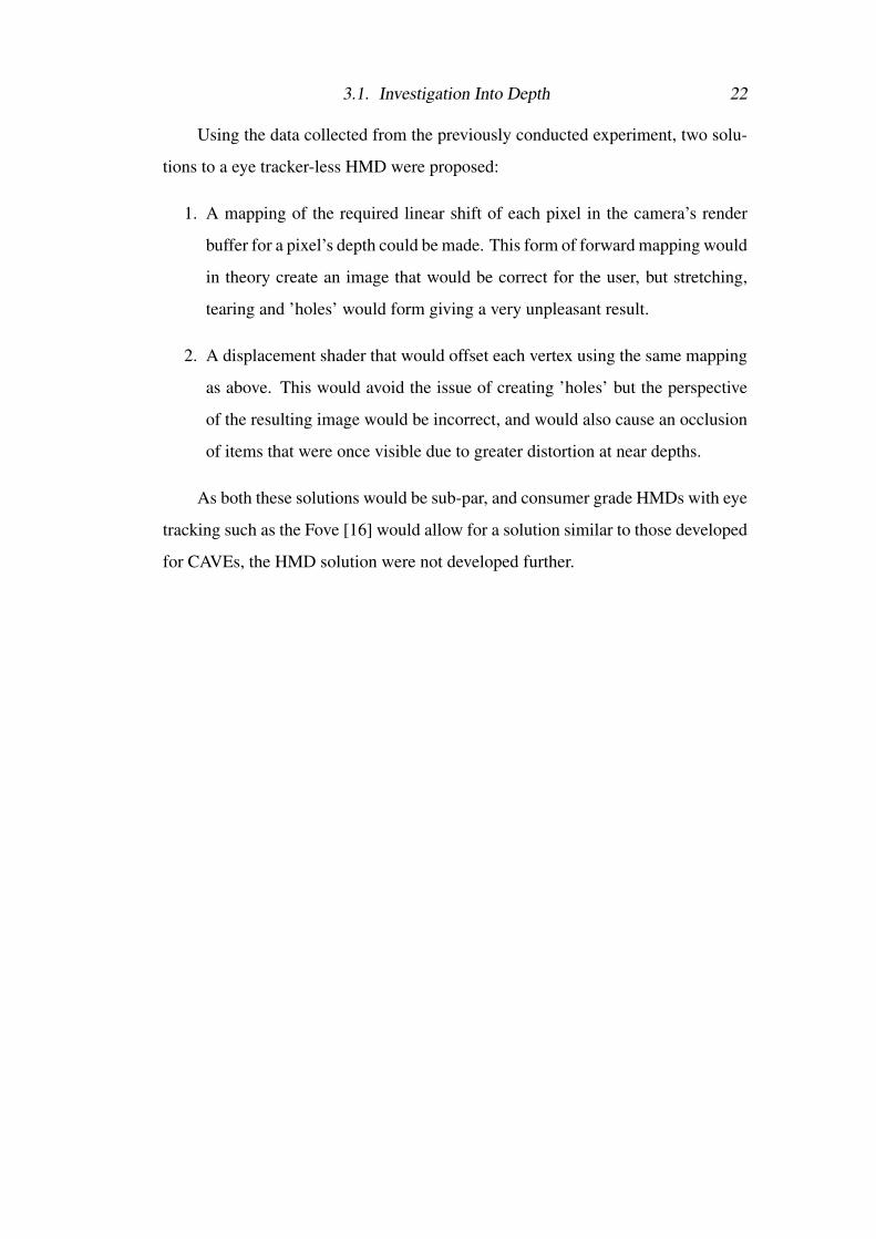
Using the data collected from the previously conducted experiment, two solu-
tions to a eye tracker-less HMD were proposed:
1. A mapping of the required linear shift of each pixel in the camera’s render
buffer for a pixel’s depth could be made. This form of forward mapping would
in theory create an image that would be correct for the user, but stretching,
tearing and ’holes’ would form giving a very unpleasant result.
2. A displacement shader that would offset each vertex using the same mapping
as above. This would avoid the issue of creating ’holes’ but the perspective
of the resulting image would be incorrect, and would also cause an occlusion
of items that were once visible due to greater distortion at near depths.
As both these solutions would be sub-par, and consumer grade HMDs with eye
tracking such as the Fove [16] would allow for a solution similar to those developed
for CAVEs, the HMD solution were not developed further.
Chapter 4
Initial Correction Prototypes
The development of the technique required to correct diplopia was the most chal-
lenging stage of the project. A great deal of investigation was undertaken in both
understanding how diplopia translates inside virtual environments, and attempting
to separate the aforementioned binocular fixation assumption.
The initial goal of this project was to work towards an AR HMD, but consid-
ering the time scale, and the fact that consumer level AR HMDs with eye tracking
are several years away at best, it was decided that this was outside the scope of the
project, and that the VR proof of concept developed within a CAVE would be the
main goal. A VR-based HMD solution was still attempted as it was assumed a pos-
sibility that the correction was linear, and thus did not require eye tracking, and no
evidence to counter this claim had yet been gathered.
Note: The term ’submissive eye’ used here refers to the misaligned eye of a
diplopia sufferer in which has weaker vision. The ’dominant eye’ refers to the main
eye in which a diplopia sufferer sees through.
4.1 Camera TranslationAnecdotal evidence from diplopia sufferers claim that the image from their submis-
sive eye appear to be positionally offset in relation to image seen by their dominant
eye. This led to the belief that the correction required would also be an offset of the
cameras projecting to that eye in the (x,y) axis, and an investigation into whether
changing the position of cameras linked to the submissive eye would allow for fu-
4.2. Camera Rotation 24
sion of the projected images.
The cameras rendering to the submissive eye were manually positioned by the
participant until a single point lined up correctly. This however changed the IPD,
essentially placing the eye of the participant on the floor. While this did align for a
single point, it was not the case for the rest of the environment. Setting the camera to
an impossible location led to the conclusion that the IPD should never be changed,
and that the location of the eye in virtual space should remain the same.
4.2 Camera RotationAs it was found that the relative position of the cameras to the user’s head should
remain constant, correction was attempted with rotation of the cameras. Matching
the rotation of the cameras to that of the submissive eye only simulated diplopia for
normal sighted, doing the inverse rotation did not correct vision diplopia.
An alternative method of achieving this would be rotating the cameras of the
dominant eye to match the misalignment of the submissive eye. Although this cre-
ated strong fusion at points, it was claimed to be very jarring having one’s vision
locked at an unnatural angle and still gave an incorrect projection.
Although much better results were obtained - allowing for an alignment of
points with less distortion - the method still suffered from the same problem: cre-
ating a different projection. This led to the conclusion that manipulation of the
cameras alone was not the solution as it always gave incorrect renderings of the
environment,
4.3 Render TranslationThe above findings show that a manipulation of neither the environment nor the
camera was a valid solution. Changing either the environment or the camera would
give the same incorrect projection to the submissive eye, and manipulating both
together would not produce a change.
This led to the conclusion that the image rendered by the camera is a correct
rendering of the environment for any user, and should not be altered.

4.3. Render Translation 25
The problem became one of manipulating the rendered image so that fusion
would occur. Experiments to test the validity of this theory were conducted using a
Google Cardboard, mobile phone and stereographic images. The stereo half-image
corresponding to the submissive eye was translated along the (x,y) axis with the
participant commenting on how successful fusion was.
Displacing the image gave fusion at specific points, but it was found that the
whole image did not fuse for the participant; there was a correlation between dis-
placement and screen position. This result however, did show that it was possible
to fuse objects without transforming the environment or camera.
(a) Normal sighted user (b) Diplopia sufferer (c) Compensated image
Figure 4.1: Image translation along projection plane meeting the submissive eye gaze andgranting fusion.
The experiment outline in chapter 3 was then developed. As the screen of the
HMD could not be physically moved, the technique of offsetting the render buffers
of each camera (rather than the screen location) was devised. Figure 4.1 shows that
fusion occurs by translating the image presented to submissive eye (dashed) such
that it meets its gaze.
As this was an iterative process, rather than spending time attempting a low
level implementation that manipulated the render buffer, the design decision was

4.3. Render Translation 26
made to simulate the effect of offsetting the rendering buffers as the result would be
similar albeit inelegant.
The projections of each camera that would normally render to the HMD were
instead displayed on two separate planes as render textures. A second set of or-
thogonal cameras were set to the same position as the original pair of cameras and
had culling masks set to only view their respective plane. These cameras were then
rendered to the HMD.
This gave a virtual viewing plane that effectively allowed for manipulation of
the cameras’ render buffers, enabling offsetting while retaining the same perspec-
tive by translating the plane in 3D space. A CAVE implementation of this system
was also developed, however its implementation will be discussed in the following
chapter due to its similarity to the final design.
The results from both implementations produced some very effective fusion
for objects and views at set depths, but perspective correctness was lost, as objects
would be rendered in different screen positions to their eventual destination, result-
ing in a change of angle between the the user’s line of sight and the corresponding
image - refereed to here as the viewing angle - as shown in figure 4.2. This became
very apparent at the periphery.
α = viewing angle of normal sighteduser and original image
β = viewing angle of diplopia suf-ferer and compensated image
α 6= β
Figure 4.2: The flaw in render translation. The change in angle between original and trans-lated image causes perspective correctness to no longer retained.

4.3. Render Translation 27
The increases in focal length combined with the change in viewing angle re-
sulted in the loss of perspective correctness. It decided that this was not a valid
solution, and that other techniques of render manipulation should be investigated.
It was now clear that the correction needed was dependant with depth and screen
location, which was in-turn dependant on the angle of the participant’s gaze, and so
the investigation into developing an HMD variant ceased as it would be challeng-
ing to effectively create such a system that would reach the minimum requirement
of success outlined in the Aims & Goals section of chapter 1, in addition to other
reasons stated in chapter 3.
The data gathered from the HMD experiments were kept for use with cross
validation with the results of the future CAVE experiments, evaluating the success
of the automatic CAVE system and the manual HMD one, and comparing the results
of each system with ground truth obtained manually from an ophthalmology exam.
Chapter 5
Final Design & Implementation
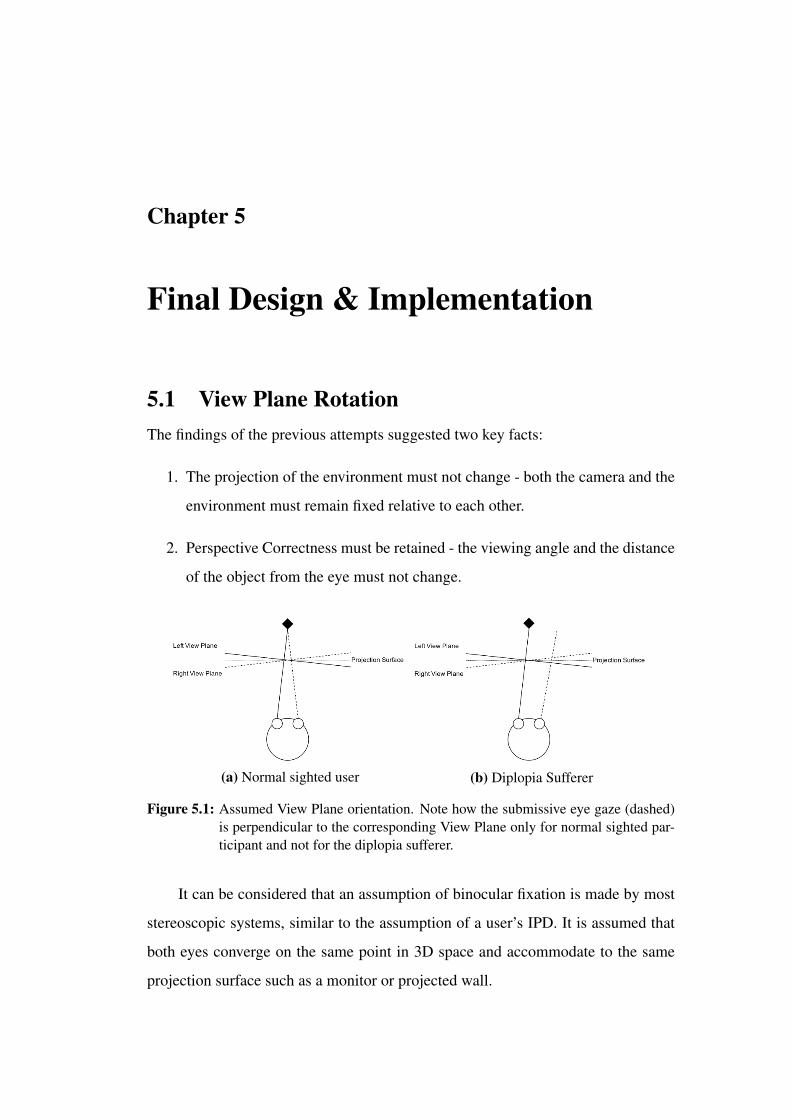
5.1 View Plane RotationThe findings of the previous attempts suggested two key facts:
1. The projection of the environment must not change - both the camera and the
environment must remain fixed relative to each other.
2. Perspective Correctness must be retained - the viewing angle and the distance
of the object from the eye must not change.
(a) Normal sighted user (b) Diplopia Sufferer
Figure 5.1: Assumed View Plane orientation. Note how the submissive eye gaze (dashed)is perpendicular to the corresponding View Plane only for normal sighted par-ticipant and not for the diplopia sufferer.
It can be considered that an assumption of binocular fixation is made by most
stereoscopic systems, similar to the assumption of a user’s IPD. It is assumed that
both eyes converge on the same point in 3D space and accommodate to the same
projection surface such as a monitor or projected wall.
5.1. View Plane Rotation 29
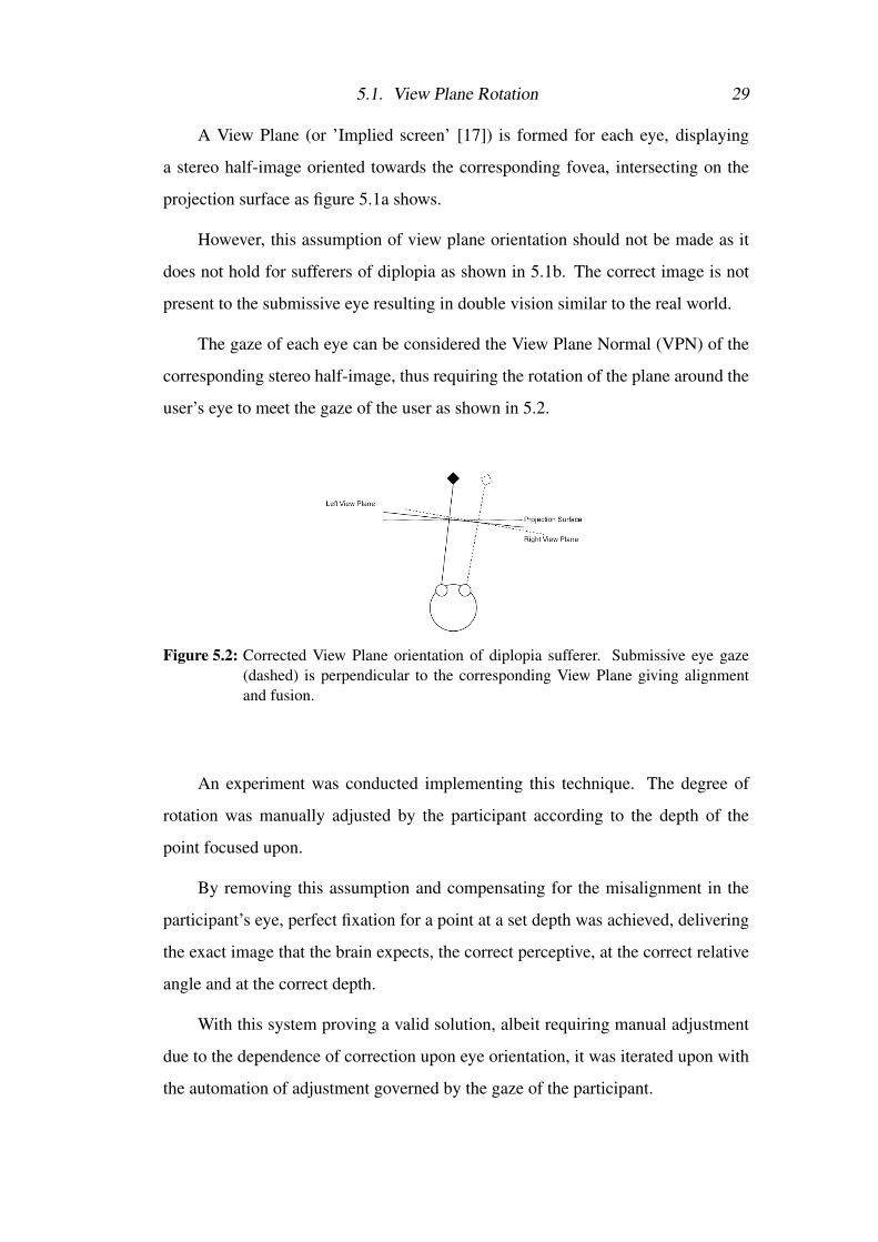
A View Plane (or ’Implied screen’ [17]) is formed for each eye, displaying
a stereo half-image oriented towards the corresponding fovea, intersecting on the
projection surface as figure 5.1a shows.
However, this assumption of view plane orientation should not be made as it
does not hold for sufferers of diplopia as shown in 5.1b. The correct image is not
present to the submissive eye resulting in double vision similar to the real world.
The gaze of each eye can be considered the View Plane Normal (VPN) of the
corresponding stereo half-image, thus requiring the rotation of the plane around the
user’s eye to meet the gaze of the user as shown in 5.2.
Figure 5.2: Corrected View Plane orientation of diplopia sufferer. Submissive eye gaze(dashed) is perpendicular to the corresponding View Plane giving alignmentand fusion.
An experiment was conducted implementing this technique. The degree of
rotation was manually adjusted by the participant according to the depth of the
point focused upon.
By removing this assumption and compensating for the misalignment in the
participant’s eye, perfect fixation for a point at a set depth was achieved, delivering
the exact image that the brain expects, the correct perceptive, at the correct relative
angle and at the correct depth.
With this system proving a valid solution, albeit requiring manual adjustment
due to the dependence of correction upon eye orientation, it was iterated upon with
the automation of adjustment governed by the gaze of the participant.

5.2. Overview 30
5.2 Overview
A CAVE can be considered as several view planes shaped in a cube, within which
a user stands. 3D glasses isolate the ’view-cube’ for each eye projected onto sur-
faces also in the shape of a cube. The rotation of this view-cube to achieve visual
correction is identical to that of a single view plane.
(a) Normal sighted user (b) Diplopia sufferer (c) Compensated image
Figure 5.3: View-cube rotation around submissive eye to meet gaze.
Figure 5.3 shows the rotation of the submissive eye view-cube (dashed), piv-
oted around the misaligned eye. The viewing angle of the object is maintained, as
the view-cube is oriented in relation to the submissive eye.
The rotational value of the view-cube is taken as the angle between the ex-
pected gaze of a normal sighted user and the gaze of a diplopia sufferer - the angular
rotation required for the expected gaze to match the actual gaze of the user.
As stated previously, the angle of rotation required for the participant is not
constant, and varies according to the depth and position of the object of interest,
giving different rotational values for each eye. It was for this reason that an eye
tracker was used, as no assumption could be made of the user’s gaze.
The data given from the eye tracker allowed for the user’s gaze to be modelled
inside the Unity 3D environment where the correctional rotation was calculated and
applied to the submissive eye view-cube enabling fusing of the environment by the
participant. This automates the previously manual and tedious process undertaken
by the participant of aligning the two stereo half-images for a set depth.
5.3. Detail 31
5.3 Detail
5.3.1 View-Cube Rotation
The software MiddleVR was used for the presentation of the environment in the
CAVE. MiddleVR is middleware designed to simplify the creation of VR applica-
tions. Using the head tracking data of the 3D glasses used in a CAVE, it is is able
to render an environment in Unity to the multitude of 3D projectors used within it.
MiddleVR separates the relationship between a screen and a display. The view-
ing frustum of a camera is determined by a screen to give correct perspective, while
a display is simply what creates the images. This separation is made as 3D pro-
jectors are commonplace for CAVEs, and the plane on which the environment is
projected - the screen - is separate to the projector itself, which is responsible for
the resolution and presentation of the image - the display.
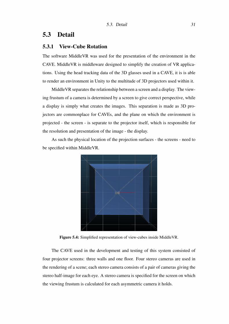
As such the physical location of the projection surfaces - the screens - need to
be specified within MiddleVR.
Figure 5.4: Simplified representation of view-cubes inside MiddleVR.
The CAVE used in the development and testing of this system consisted of
four projector screens: three walls and one floor. Four stereo cameras are used in
the rendering of a scene; each stereo camera consists of a pair of cameras giving the
stereo half-image for each eye. A stereo camera is specified for the screen on which
the viewing frustum is calculated for each asymmetric camera it holds.
5.3. Detail 32
As seen in figure 5.4 the viewing frustums of each stereo camera creates an
implied view plane for each eye, but makes the assumption stated in figure 5.1b of
view plane orientation. This can be corrected in a similar fashion shown in figure
5.2.
It can be considered that the stereo cameras use the screens to generate two
separate implied view-cubes. By creating a new set of screens and defining these
for the cameras responsible for a specific eye, each view-cube can be controlled
separately through manipulation of the corresponding screens.
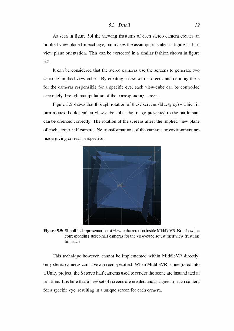
Figure 5.5 shows that through rotation of these screens (blue/grey) - which in
turn rotates the dependant view-cube - that the image presented to the participant
can be oriented correctly. The rotation of the screens alters the implied view plane
of each stereo half camera. No transformations of the cameras or environment are
made giving correct perspective.
Figure 5.5: Simplified representation of view-cube rotation inside MiddleVR. Note how thecorresponding stereo half cameras for the view-cube adjust their view frustumsto match
This technique however, cannot be implemented within MiddleVR directly:
only stereo cameras can have a screen specified. When MiddleVR is integrated into
a Unity project, the 8 stereo half cameras used to render the scene are instantiated at
run time. It is here that a new set of screens are created and assigned to each camera
for a specific eye, resulting in a unique screen for each camera.

5.3. Detail 33
Rotation of the submissive camera screens are set within Unity at run time,
affecting the projection of the environment through the steps detailed above, giving
corrected vision for the participant within the CAVE for a point.
5.3.2 Calculation of Correct Orientation
As previously mentioned, the angle of orientation for the set of submissive screens
is the rotational difference between the expected gaze vector and the actual gaze
vector of the user. This expected gaze vector can be extrapolated using gaze of the
dominant eye to determine their focal point, thus both eyes need to be modelled.
Within the Unity run time two sets of ’virtual eyes’ game objects are instanti-
ated. These sets model both the expected and actual gaze vectors of the user. Each
set contains a game object for each eye, and are located at the assumed position of
the user’s eyes about the head tracker, and offset by the IPD value set within Mid-
dleVR. These sets are parented to the head tracker such that they mimic the location
of the user’s eyes as they move inside the CAVE.
(a) Actual eye gaze vector set toarbitrary orientationDominant eye gaze (solid)Submissive eye gaze (dashed)
(b) Expected submissive gaze set to meetpoint hit by actual dominant ray cast.Expected dominant gaze set to matchactual dominate orientation
Figure 5.6: Extrapolation of expected gaze vectors.
A dominant eye is chosen. This is the eye which the participant primarily sees
through. The rotational values of both expected eyes are controlled by that of the
actual dominant eye. The expected dominant eye is set to the same orientation as its

5.3. Detail 34
actual counterpart, while the expected submissive eye orientation is extrapolated, as
seen in figure 5.6.
The actual dominant eye ray casts into the scene against any mesh colliders
and returns a point (if any). The expected submissive eye is then set to look at that
point. If no point is present, or if the point is occluded from the submissive eye
by another object, then no rotational changes are made to the submissive screen set
and they are set back to their original transformation. This accounts for edge cases
where occlusion of an object for one eye occurs, such as peering round a wall with
one eye still covered by this wall.
Assuming the point is visible, the rotational difference between the orientation
of the expected submissive eye and the actual submissive eye is taken.
Difference = local rotation of expected eye - local rotation of actual eye
Figure 5.7: Calculation of rotational difference α between expected and actual eye gaze inEuler angles.
This rotational difference is then applied to the submissive screen set, pivoted
around the submissive eye, thus matching the orientation of the view-cube to that
of the submissive eye.
5.3.3 Eye Tracking
So far a manual correction system has been described. As the eye gaze of the user is
integral to the system meeting the success criteria, the user’s eyes must be tracked.
The EyeLink II by SR research was used to gain this data. It is a high speed,
5.3. Detail 35
accurate head mounted video based eye tracker that consists of three cameras, one
looking at each eye of the participant, and a third infra-red camera designed to detect
markers place in the world.
The system was designed primarily for conducting experiments on a 2D screen
outlined by IR markers and situated close to the participant, and not necessarily for
tracking the gaze of a subject as they moved within a CAVE. However, while some
features of the EyeLink system couldn’t be used, it was very versatile and allowed
for gaze tracking of the participant in the virtual environment.
The standard output of the EyeLink was the (x,y) coordinates of the user’s
gaze on the IR marked screen. The IR markers were used to calculate and drift
or movement that might occur during an experiment. This was not suitable for a
CAVE environment, which has multiple screens displaying 3D images.
Instead, Head referenced (HREF) (x,y) coordinates were used. HREF is the
direct measurement of each eye rotation angle relative to the head. This is ideal for
the system as only the angle of the eyes need be obtained. The depth of the user
from the display is not taken into account in the calculation of these values, but this
is not a concern as the displays inside a CAVE are merely projection surfaces of the
environment which is ray cast into.
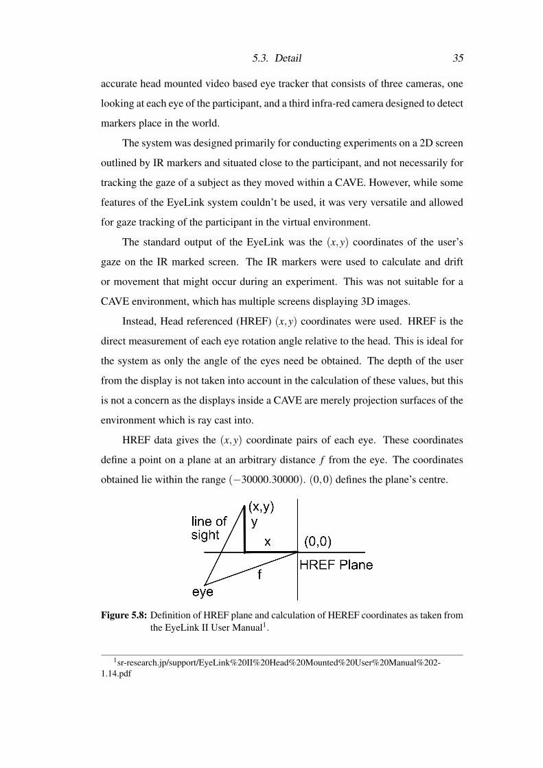
HREF data gives the (x,y) coordinate pairs of each eye. These coordinates
define a point on a plane at an arbitrary distance f from the eye. The coordinates
obtained lie within the range (−30000.30000). (0,0) defines the plane’s centre.
Figure 5.8: Definition of HREF plane and calculation of HEREF coordinates as taken fromthe EyeLink II User Manual1.
1sr-research.jp/support/EyeLink%20II%20Head%20Mounted%20User%20Manual%202-1.14.pdf

5.3. Detail 36
Using HREF values, the angle of rotation of the eye around the (x,y) axis for
a set of coordinates (x,y) can be taken.
θx = tanyf
(5.1)
θy = tanxf
(5.2)
Figure 5.9: Calculation of eye (x,y) axis rotation in Euler angles
Note the angle of rotation around an axis is given by the opposite coordinate -
that is, the rotation around the y axis is given by the corresponding x value and visa
versa.
The EyeLink II is connected to its own computer that is queried with requests
for data. Aside from this ’Host PC’ and the computer on which the CAVE simula-
tion is rendered (or ’CAVE PC’), a third computer is used to calibrate the tracker,
as well as parse and transfer the data to the CAVE PC.
The implementation of SR Research’s API was challenging. Instead of cre-
ating a fully contained program, the calibration and validation process was done
by a sample project supplied by SR Research. After correct positioning and focus-
ing of the cameras, the participant is tasked with looking at different points on the
calibration monitor with minimal head movements. This process establishes a rela-
tionship between the participant’s gaze and the outside world. After calibration and
validation, the participant is moved into the CAVE to begin the experiment.
TCP connections are opened by this ’Experiment PC’ to both the Host PC
and CAVE PC. A request is made to the Host PC to start the recording of the user’s
gaze and commences looping the act of attempting to receive the most recent HREF
samples from the Host PC, and sending these samples off to the CAVE PC.
In order to talk to the Host PC, a static IP address must be set, and a monitor
outlined with IR markers is required for calibration and validation. It was for these
reasons that it was decided that a separate computer would be tasked with gathering
the data from the eye tracker.
A TCP thread in the Unity runtime listens for this HREF data and calculates the

5.3. Detail 37
Euler angles as shown in equation 5.9. The orientation of the actual eye game ob-
jects are then set based on these values, giving an accurate representation of where
the user is looking in the virtual environment.
Using this eye data, the eyes of the participant are modelled, which generate
the rotational difference required to compensate the orientation of the submissive
eye view-cube, and thus correct the participant’s vision.
5.3.4 Drift Correction
Any movement of the participant after the calibration and validation process would
cause slippage of the EyeLink headband, resulting in the raw data given from the
headband to be incorrect. In a standard experiment, the IR markers located around
the monitor would minimise any errors in the data received from the eye tracker.
Drift Correction is also performed: the participant fixates on a single point in the
centre of the monitor with minimal head movement. This would correctly offset the
raw data given by the headband.
Headband slippage was unavoidable for this experiment as the participant
would move within the CAVE. A severe drift formed from the brief movement of
the participant standing up from the experiment monitor and entering the CAVE and
as such, the techniques used for standard experiments were not applicable.
The decision to calibrate and validate outside of the CAVE was made due to
several factors. Even though the participant would later have to move into the CAVE
and create drift, the standard calibration and validation processes were extremely
robust. Moreover, these processes required the use of IR markers, and the size and
shape of the CAVE would not easily permit such a modification - only four markers
are supplied with the EyeLink II, and it is not believed that it designed to support
more, nor in the configuration that would be required in the CAVE.
Without the presence of IR markers, and by using HREF coordinates, no
changes to the user’s head position and angle were taken into account, which made
it very prone to slippage. As a result of this decision, a new drift correction system
for the 3D environment had to be created; any correction performed on the calibra-
tion monitor would be moot after the participant has entered the CAVE. Only drift
5.3. Detail 38
correction and not a full calibration and validation system was implemented within
the CAVE.
The IR markers are used by the EyeLink as reference points to map the gaze of
the participant to the world. This would not be needed as the outside-in tracking sys-
tem of a CAVE gave the same if not more reliable reference data than the inside-out
tracking of the EyeLink. Time constraints however meant that what limited devel-
opment time left was focused towards the proof of concept of the visual correction
system, and not on creating a robust eye tracking system in a virtual environment.
Emulating a similar process to its 2D counterpart, the drift correction system
would present a marker in front of the participant, which would then be focused
upon. This marker consists of a coloured cube with a white sphere enclosed around
it, giving a precise, clear reference point to focus on. To ensure the marker remained
correctly positioned in the middle of the participant’s visual field, it was parented to
the participant’s head movements.
All previous drift correction and visual correction is disabled for this process
to give an accurate result and minimise the disorientation that severe drift can cause.
After the participant had successfully focused on the marker, the marker is hidden,
the drift is calculated and compensated for, and visual correction resumes.
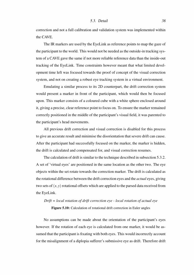
The calculation of drift is similar to the technique described in subsection 5.3.2.
A set of ’virtual eyes’ are positioned in the same location as the other two. The eye
objects within the set rotate towards the correction marker. The drift is calculated as
the rotational difference between the drift correction eyes and the actual eyes, giving
two sets of (x,y) rotational offsets which are applied to the parsed data received from
the EyeLink.
Drift = local rotation of drift correction eye - local rotation of actual eye
Figure 5.10: Calculation of rotational drift correction in Euler angles
No assumptions can be made about the orientation of the participant’s eyes
however. If the rotation of each eye is calculated from one marker, it would be as-
sumed that the participant is fixating with both eyes. This would incorrectly account
for the misalignment of a diplopia sufferer’s submissive eye as drift. Therefore drift

5.3. Detail 39
is corrected in each eye independently. The marker presented to the participant is
only viewable to one eye at a time. This ’monocular mode’ occupancies the ’binoc-
ular mode’ previously stated, giving a system that performs drift correction for both
normal sighted and visually impaired users.
Note the rotational values of the drift correction eyes are actually a constant as
the marker does not move. It was decided to keep the current functionality as the
system could be extended with drift correction markers in multiple positions, that
would measure the rotation of the each eye, and not use a constant value.

Chapter 6
Testing & Analysis
6.1 TestsThe following experiment was conducted with two participants: the author, who
has diplopia, and a normal sighted participant, who was used as a control.
After calibration and validation, participants entered the CAVE and were
tasked with looking around a virtual environment containing multiple objects at
different depths. The gaze of the participant was indicated by a yellow marker. If
the participant felt that the system was not correctly indicating where they were
looking, drift correction was performed.
The depth, rotation, and the correctional difference of both eyes were logged
at every frame. Participants were also asked to comment on the experiment, and to
relate how well they felt the system worked. After several minutes in the CAVE,
the experiment was terminated.
6.2 AnalysisBoth participants stated that fusion occurred on near objects after drift correction.
This shows that the theory holds for both types of vision. The gaze was tracked well
from both participants on close objects, and these results reflect that.
However, gaze was poorly tracked on the periphery and for objects at great
depth, resulting in some disparity for both participants. Poor calibration and valida-
tion was a major concern for this project, as accurate eye tracking was integral to the
correction of vision, and any errors in the reported angle were compounded at great

6.2. Analysis 41
distances. Participants focused on a near object for majority of the time spent in the
CAVE; this is when the system performed best. With the gaze accurately reported
and kept in a somewhat constant position, the system was successful in enabling
fusion for both participants as they moved around objects close to them.
Figure 6.1: Rotational correction required for both a normal sighted and diplopia sufferingparticipant.
Figure 6.1 shows the results obtained for one experiment run of each partic-
ipant. While there is quite a lot of noise in these results, it can be seen that the
mean of x axis rotation for diplopia sufferer is centred around −1deg, where as the
normal sighted participant is centred around 0deg, as would be expected.

6.2. Analysis 42
As participants focused on close objects for the majority of the experiment, it
may have influenced the data somewhat. The noise and general outliers could be a
result of poor calibration or the presence of drift.
The data gathered from the system is challenging to analyse, but participants
have stated that it does meet the criteria for success outlined in chapter 1.

Chapter 7
Conclusion
7.1 Summary
The main goal of this project was to create a proof of concept computer system
to correct diplopia caused by strabismic amblyopia; to allow for the fusion of two
stereo half-images for a user as they move within the Virtual Environment.
It is felt that the system presented here does indeed achieve this goal, as the
main participant (the author) who suffers from such a condition was able to achieve
stereo fusion. This was achieved through the manipulation of the view plane pre-
sented to the misaligned eye and the autonomous control of of an eye tracker.
One of the aims of this project was to see if depth perception or stereoscopy
occurred in the participant. Unfortunately, this was not the case as the quality of
eyesight in the participant’s submissive eye is so poor, that only complete suppres-
sion of the image was achieved. Stereo fusion had occurred, but with minimal
increase in the perception of depth, as the participant still dominantly saw through
one eye.
It should also be noted that the correction given by this system is not exclu-
sively for sufferers of strabismic amblyopia based diplopia. The theory states that
the orientation applied is equal to the rotational difference between the expected and
actual submissive gazes. This means that the fully sighted should see no difference,
and it should give correct vision for the forms of diplopia, like ophthalmoplegia suf-
ferers who cannot move the muscles of an eye resulting in the eye fixing in place.

7.2. Critique 44
The goal of creating an HMD based VR or AR system was unfortunately not
met due the time and hardware constraints. The (theoretical) HMD variant of this
system would use a technique similar to render texture translation previously men-
tioned, with the virtual plane on which the buffer is presented matching the orien-
tation of the submissive eye. A drawback of an HMD implementation is the low
FOV on some models. A CAVE - which provides an encompassing FOV - would
not have as great an issue as some HMDs. that lack of peripheral vision and cum-
bersome corrections might cause the plane to ’spill’ off the edge of the display.
The long term goal of gathering more participants with visual impairments,
or ’faking’ diplopia using fully sighted participants with prism shifting glasses was
not achieved as the time frame of this project did not allow for it. Access to prism
shifting glasses was also not easily available.
7.2 Critique
The final solution worked well in the majority of situations: when the centre of an
object in the close-to-middle distance was the focal point of the participant’s gaze,
fusion was achieved for both. Gaze is critical to this project, and it was the eye
tracker that caused the majority of any instability during the project.
The modelling of the user’s gaze was never perfect, but as long as the user
focused on the centre of an object, the system behaved as expected. However, if the
user was looking at the edge of an object, the reported gaze by the system might
fall behind the object, creating a jarring misalignment, often resulting in the system
flitting between assuming they were focusing behind the object and in front of it,
turning the correction of view-cube into a very unconformable experience.
Drift correction had to frequently be performed as the nature of the experiment
caused a lot of headband movement. Drift correction was implemented late in the
development process, and is reflected in the presence of some bugs that affect the z
axis of the correction orientation.
This system was hard to develop for, as the bespoke hardware of the eye tracker
and the CAVE made developing for it very challenging. Most of the system devel-

7.2. Critique 45
opment had to happen inside the CAVE, and due to the demand for time in the
CAVE, only a few hours a week could be spent inside it.
It was for this reason that the HMD and Google cardboard solutions were the
main focus of initial development, as only basic principles could be tested for the
CAVE when it was not available. The development of an HMD variant was stopped
shy of the final design. Implementing the final design sans the eye tracking would
require little effort, but the effectiveness of such a system would be questionable.
Availability of high quality HMDs with eye tracking was the main limitation to-
wards this implementation.
For the final design, both the input data (eye and head tracking) and output
data (cave rendering) couldn’t be obtained remotely, or by other means easily. It
was only until late in development, when the valid correctional concept had been
discovered, that this data was able to be ’faked’.
As the orientation the view-cubes took was more important than the stereo out-
put of the CAVE at this point in development, and because the HREF data structure
was now known, both the input and output could be mimicked via a video game
controller. Being able to mimic the data sent by the eye tracker, and observing how
the system behaved in orienting view-cube representations, bugs and errors were
quickly picked up without concern of setting up TCP connections, calibrating en-
cumbering hardware, or CAVE availability constraints. Earlier use of this technique
would have greatly increased the efficiency of project development.
The need for the system to monitor both eyes is in fact redundant. The drift
correction process effectively maps the gaze of a user to the virtual environment,
allowing the orientation of the submissive eye to be known. The submissive view-
cube would then following the orientation of the eye, regardless of the where the
dominant eye’s gaze fell.
This would mean that only the submissive eye would need to be tracked, cal-
ibrated in a similar way to drift correction, halving the potential for error from the
eye tracker and removing a great deal of processing from the CAVE PC. There was
not time to implement this new system however, and although the improvement

7.3. Future work 46
robustness is obvious, the system is designed to be a proof of concept, which it
successfully is.
The system does not fully implement the concepts described in this report; a
flaw in the implementation of the view-cube rotation was discovered. The pivot
around which the view-cube rotates was not considered, and centre of the cube
was used as the pivot. This was incorrect, and could explain some of the flaws in
the system. The rotation should in fact be around the user’s submissive eye (the
system actually simulated this in the calculation of the rotation, it was only in the
orientation setting of the view-cube that this error occurred.) However, the concept
described in the report correctly considered the pivot of the view-cube rotation.
The system makes the common assumption of the user’s IPD. This can affect
accuracy of projection if incorrectly set, and is a potential source of error in the
results obtained. However this is a minor concern as the IPD is rarely far from the
truth, it can easily be adjusted for in the system.
Given all these flaws, the concept of the project has still been proven, produc-
ing a system that corrects vision for the visually impaired in a virtual environment.
7.3 Future workGiven more time, improvements in the eye tracking portion of the system would be
made, namely increasing the accuracy and performance of gaze calculation.
The CAVE system however is simply a proof of concept for an AR based HMD
variant that would give correction to the visually impaired in the real world. Cam-
eras on the outside of the HMD would render perspective-correct images of the
world. These images would be displayed on virtual View Planes, rotated around the
eyes of the user to match their orientation. Only the misaligned eye would need to
be tracked, so this theoretical system could only function for a single eye.
The hardware required for such a technology is decades off however, as con-
sumer level AR HMDs are yet to be successful; this too is the case with eye tracking
within a HMD. The technology used to build this system must be of consumer grade
components if it is expected to be a cheaper alternative to prism shift glasses.

7.4. Final Thoughts 47
Experiments with more participants who have a wider range of visual impair-
ments would be conducted. This would allow for a more critical evaluation of the
system, as well as a more in-depth analysis of its limitations. The limited pool
of test participants used during the development of the system was accounted for
however, as the concept discussed are designed to be as generic as possible.
The calculation of the dominant eye’s focal point currently only works with
mesh colliders. This limits the portability of the system into new environments, as
objects like UI elements will not have colliders within the virtual environment, and
thus an incorrect adjustment is made, if any at all. This is a result of using Unity’s
in-built ray cast system. A new ray casting system would have to be implemented
to resolve this. This is only the case if the alteration stated in 7.2 is not made. If the
non ray casting system was implemented, then this would not be needed. Therefore,
either the choice of the implementation of these adjustments, or the creation of a
new ray cast system would be made.
The results of the system tests show that the visual impairment of the partic-
ipant were documented. Given more time, an investigation into how this system
could improve accuracy and potential diagnosis of visual impairments could prove
beneficial to the field of ophthalmology.
7.4 Final ThoughtsIt has been shown that here is an assumption in the orientation of a user’s gaze made
by stereoscopic systems, that results in an incorrect orientation of the implied view
plane for each eye. This assumption should no longer be made as it has shown that
this system works for both the visually correct and impaired.
Although there is a requirement of eye tracking the user, rapid advancements
in hardware should soon allow for the intergeneration of the concepts displayed by
this novel system into stereoscopic displays, creating a new form of accessibility
for the visually impaired that may allow some to see better in a virtual world then
they do in the real world.

Bibliography
[1] Vive, 2016. [Online]. Available: https://www.htcvive.com/uk/.
[2] Hololens, 2016. [Online]. Available: https : / / www . microsoft . com /
microsoft-hololens/en-us.
[3] Amblyopia — wikipedia, 2016. [Online]. Available: https : / / en .
wikipedia.org/wiki/Amblyopia.
[4] Prism use in adult diplopia. [Online]. Available: http://www.medscape.
com/viewarticle/771807.
[5] I am stereoblind, but the oculus rift is my corrective lens, 2016. [Online].
Available: http : / / www . vognetwork . com / rifting - to - a - new -
reality/118/I-Am-Stereoblind-But-The-Oculus-Rift-Is-My-
Corrective-Lens/.
[6] 3ds has seemingly improved my eyesight, 2016. [Online]. Available: http:
//www.gamespot.com/forums/nintendo-fan-club-1000001/3ds-
has-seemingly-improved-my-eyesight-28348257/.
[7] O. Gary Heiting, Amblyopia news: Children with lazy eye read more
slowly, 2016. [Online]. Available: http://www.allaboutvision.com/
conditions/amblyopia.htm.
[8] M. P. Robert, F. Bonci, A. Pandit, V. Ferguson, and P. Nachev, “The scoto-
genic contact lens: A novel device for treating binocular diplopia,” British
Journal of Ophthalmology, vol. 99, no. 8, pp. 1022–1024, 2015. DOI: 10.
1136/bjophthalmol-2014-305985.
BIBLIOGRAPHY 49
[9] Diplopia - a virtual reality game to help lazy eye (amblyopia and strabismus),
2016. [Online]. Available: https://www.diplopiagame.com/.
[10] Double vision − causes, 2016. [Online]. Available: http://www.nhs.uk/
Conditions/Double-vision/Pages/Causes.aspx.
[11] Double vision − treatment, 2016. [Online]. Available: http://www.nhs.
uk/Conditions/Double-vision/Pages/Treatment.aspx.
[12] M. A. Tamhankar, G.-s. Ying, and N. J. Volpe, “Success of prisms in
the management of diplopia due to fourth nerve palsy,” Journal of Neuro-
Ophthalmology, vol. 31, no. 3, pp. 206–209, 2011. DOI: 10.1097/wno.
0b013e318211daa9.
[13] D. Wroblewski, B. A. Francis, A. Sadun, G. Vakili, and V. Chopra, “Testing
of visual field with virtual reality goggles in manual and visual grasp modes,”
BioMed Research International, vol. 2014, pp. 1–10, 2014. DOI: 10.1155/
2014/206082.
[14] J. E. Cutting, “How the eye measures reality and virtual reality,” Behavior Re-
search Methods, Instruments, & Computers, vol. 29, no. 1, pp. 27–36, 1997.
DOI: 10.3758/bf03200563.
[15] J. Roodhooft, “Screen tests used to map out ocular deviations,” Bulletin de la
Societe Belge d’Ophtalmologie, vol. 305, pp. 57–68, 2007.
[16] Fove, 2016. [Online]. Available: http://www.getfove.com/.
[17] Good stereo vs. bad stereo, 2012. [Online]. Available: http://doc-ok.
org/?p=77.
[18] D. Gadia, G. Garipoli, C. Bonanomi, L. Albani, and A. Rizzi, “Assessing
stereo blindness and stereo acuity on digital displays,” Displays, vol. 35, no.
4, pp. 206–212, 2014. DOI: 10.1016/j.displa.2014.05.010.
[19] Diplopia — wikipedia, 2016. [Online]. Available: https://en.wikipedia.
org/wiki/Diplopia.

BIBLIOGRAPHY 50
[20] Sr research support site. [Online]. Available: https://www.sr-support.
com/forum.php.
[21] Eyelink ii user manual. [Online]. Available: http://sr-research.jp/
support/EyeLink%20II%20Head%20Mounted%20User%20Manual%202-
1.14.pdf.
[22] Eyelink programmer’s guide. [Online]. Available: http : / / www . ulab .
uni - osnabrueck . de / anleitung / manuale / manual _ eyelink -
programmierung.pdf.
[23] Middlevr user guide. [Online]. Available: http://www.middlevr.com/
doc/current.
[24] Unity - scripting api: [Online]. Available: http://docs.unity3d.com/
530/Documentation/ScriptReference/index.html.
[25] Tcp code modified from unity forum. [Online]. Available: http://answers.
unity3d.com/questions/12329/server- tcp- network- problem.
html.

Appendix A
System Manual
A.1 Overview
There are two separate branches of this system. CAVE and HMD. the CAVE branch
is more developed, consisting of two main components: a Unity 3D project written
in C#, and a TCP client program written in C++.
The code is located publicly on a GitHub repository1containing the three pro-
grams outlined bellow, as well as supporting material such as EyeLink documenta-
tion and the required library and header files for interacting with the EyeLink.
A.2 CAVE System
The CAVE system incorporates full visual correction for a diplopia suffer using a
Cave Automatic Virtual Environment and the EyeLink II eye tracker. The CAVE
uses a combination of Unity 3D (Ver. 5.3.4) & MiddleVR (Ver. 1.6.1) on one
PC to render the environment, and DTrack 2 & VRPN on another to handle the
head tracking of the user. The EyeLink II tracks the gaze of the user which is
sent to the Unity application. The gaze of the user is modelled, and the rotation
correction required is calculated and applied to the set of View Planes that project to
the misaligned eye within the CAVE, correcting the user’s vision within the virtual
environment.
1https://github.com/SnubbleJr/DiplopiaCorectionViaVE
A.2. CAVE System 52
A.2.1 Technical Specification
The following is the technical specification used in the creation of the system. It is
the recommend, but not minimum specification needed.
Rendering PC
• Intel Core i7-3930K CPU, 3.2GHz
• 32Gb RAM
• Nvidia quadro K5000 GPU
Projectors
• Graphics setup is for 5600x1050 display with 96Hz refresh rate
• Display is divided into three 1400x1050 projections for each of the vertical
walls, and 1100x1050 for the floor (the floor projection is clipped at the sides
so that it is approximately square)
• Shutterglasses used are Volfoni ActivEyes
ART tracking
• Trackpack4 (6 cameras) optical system
EyeLink II
• An EyeLink II eye tracking head set and accompanying host PC & IR markers
are required.
(See accompanying EyeLink user guide for more information [21].)
Experiment computer
• A computer with two network cards. This is needed for the transferring of
data from the EyeLink II host computer to the computer used for rendering
inside the CAVE.
Misc
• A sever on which VRPN and DTrack is needed to run

A.2. CAVE System 53
A.2.2 Set Up
Further details for setting up a CAVE will not be given; access to a CAVE is assumed
henceforth.
Experiment & host PC
The computer used to forward data between the host PC and render PC - referred to
as the experiment PC by the EyeLink - requires its monitor to be outlined with the
supplied IR markers. This is for the calibration and validation of the eye tracker.
This computer also requires two network cards. Ensure one is set to the static IP ad-
dress 100.1.1.2, and subnet mask 255.255.255.0. Connect the host PC via Ethernet
cable to static networking card of the experiment PC.
Connect the EyeLink II with the host PC as per the instructions of the user
manual (a copy of which is in the EyeLink Supporting Material folder).
Two separate programs are run on experiment PC, these are located in the
’EyeTracker for CAVE’ directory. The directory labelled ’Calibration and Valida-
tion’ contains the example program ’simple.exe’, supplied by SR Research used for
the calibration and validation of the eye tracker, and not extended upon.
Within the directory ’Send data to cave’ is the Visual Studios solution ’sim-
pleexample.sln’. This solution forwards data from the host PC to the Unity project
running on the rendering PC. The EyeLink API [22] can be found in the supporting
materials folder.
Note: errors about the dependencies of the header and lib files may occur,
make sure the relative file paths correctly link to the ’includes’ and ’libs’ directories
supplied in the ’EyeTracker for CAVE’ directory. Copies are also included in the
supporting material folder.
Unity Project
Located within the ’CAVE’ directory, the unity project root is labelled ’EyeDis-
placement’. The MiddleVR asset packed must be included within the Unity project.
Opening the scene ’scene.unity’ will present several game objects.
The game objects ’VRManager’, ’GazeCaster’ and ’Shift’ must be kept in the

A.2. CAVE System 54
scene. Make sure the correct configuration file (’CAVE/config.vrx’) is selected by
the VR Manager.
GazeCaster is the main object used for receiving EyeLink data and simulating
the user’s gaze. The GazeCasterManager script is used to customise the experiment
to be run. Here, the dominant eye of the participant can be set, as well as the option
to log their gaze during the experiment. This data is contained within the ’Logs’
folder of the build’s data directory, containing the rotation of the user’s eyes as well
as the correctional rotation needed for an object at a specified depth.
The type of drift correction can be set to reflect the type of experiment that is
to be run. Binoculars should be used for fully sighted participants, while monocular
is intended for the visually impaired. The (x,y) offset of the correction marker can
is modifiable in the inspector.
The use of test inputs or outputs can also be set; mimicking the gaze input that
would be sent from the EyeLink with a controller, or visualising the resultant screen
rotation that would be output.
Note: make sure the IP addresses set in the TCPListener script on GazeCaster
and in simpleexample.sln on the experiment PC are set to the address of the render-
ing PC.
A.2.3 Run Order
Outlined is the basic operational order of an experiment. This is further outlined in
the User Manual
1. Activate DTrack and VRPN server - MiddleVR should be able to pick up
head tracker movement of glasses
2. Run simple.exe, calibrate and validate EyeLink. Exit after good calibration
achieved
3. configure experiment within Unity, build and run
4. Run simplExample, data should now be sending, gaze should be tracked by
yellow sphere

A.3. HMD portion 55
5. Perform experiment. Data can be logged once wand button 2 (defined in
MiddleVR) is pressed
6. Perform drift correction if needed
7. Once finished, press space bar on experiment PC to stop sending to unity, stop
recording EyeLink data
A.3 HMD portionLocated with the ’HMD’ directory is the Head Mounted Display branch of the sys-
tem. This system is capable of view plane translation and independent rotation and
translation of each stereo half camera. Although not implemented, the addition of
view plane orientation is well within scope.
A.3.1 Technical Specifications
HMD
• An Oculus Rift DK2 was used in the development of this system. As Unity 3D
(Ver. 5.3.4) was used, this specific HMD is not required, and any compatible
display should be adequate.
Computer
A powerful enough computer is required to run VR based Unity applications, the
following is the recommenced, but not the minimum specification to run tests on
• Intel Core i7-4790k CPU, 4.4Ghz
• 16 GB DDR3 2133MHz RAM
• Nvidia GTX 970 4GB GPU
A.3.2 Set Up
The set up for this system is straightforward.
Set up the HMD to such that it can be recognised with Unity. Two scenes
are supplied. ’Experiment.unity’ is used for running experiments. ’Normal cross

A.3. HMD portion 56
scene.unity’ is used for testing and checking to see if the individual camera set up
generates the same images as unity’s built in stereo camera.
Within the scene Experiment are two game objects that are required to run an
experiment: ’ModePicker’ and ’Camera Rig’. One of two experiments can be run
with this system - the flag ’Shift Texture’ on ModePicker indicatedswhether view
port translation or camera translation & rotation is performed.
The experiment can be run directly within the editor. Operational instructions
for the user are located in the User Manual.
The texture shift experiment will yield data of the correctional shift required to
align objects in a CSV format. The camera shift will not. The code could be easily
extended to implement this however.

Appendix B
User Manual
B.1 CAVEIt is assumed that a CAVE, EyeLink II system and the required PCs have been
set up. If more information is required, refer to the included System Manual for
specification and set up instructions.
B.1.1 Experiment Configuration
Configure the experiment in unity, picking the participant’s dominate eye, and drift
correction type. If they are a diplopia sufferer, then the dominant eye should be
set to the eye that they mainly see out off; the drift correction should be set to
monocular. If the participant is normal sighted, then chose which either eye they
have stronger vision in, and drift correction to binocular.
Build and run the experiment once correctly configured, the CAVE should now
show the environment in 3D and tracking the glasses.
Figure B.1: Monitor set up. Host PC monitor (left) Experiment PC monitor (right).
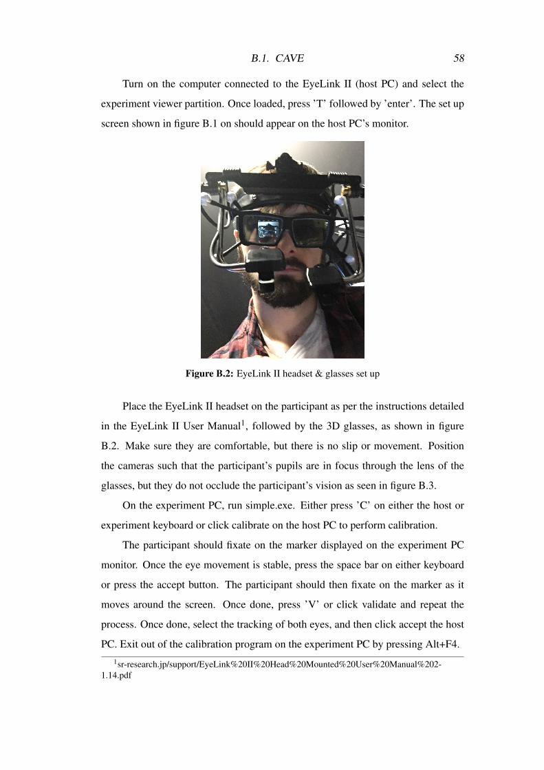
B.1. CAVE 58
Turn on the computer connected to the EyeLink II (host PC) and select the
experiment viewer partition. Once loaded, press ’T’ followed by ’enter’. The set up
screen shown in figure B.1 on should appear on the host PC’s monitor.
Figure B.2: EyeLink II headset & glasses set up
Place the EyeLink II headset on the participant as per the instructions detailed
in the EyeLink II User Manual1, followed by the 3D glasses, as shown in figure
B.2. Make sure they are comfortable, but there is no slip or movement. Position
the cameras such that the participant’s pupils are in focus through the lens of the
glasses, but they do not occlude the participant’s vision as seen in figure B.3.
On the experiment PC, run simple.exe. Either press ’C’ on either the host or
experiment keyboard or click calibrate on the host PC to perform calibration.
The participant should fixate on the marker displayed on the experiment PC
monitor. Once the eye movement is stable, press the space bar on either keyboard
or press the accept button. The participant should then fixate on the marker as it
moves around the screen. Once done, press ’V’ or click validate and repeat the
process. Once done, select the tracking of both eyes, and then click accept the host
PC. Exit out of the calibration program on the experiment PC by pressing Alt+F4.1sr-research.jp/support/EyeLink%20II%20Head%20Mounted%20User%20Manual%202-
1.14.pdf

B.1. CAVE 59
Figure B.3: Positioning and focusing of EyeLink cameras. The participant’s pupil is clearlyvisible and is as large as possible.
Note: make sure that you get a ’good’ calibration on both eyes.
Run simplExample. Data should now be sent to the unity application within
the CAVE. Coordinate data should be now updating on the walls.
Now in the cave, a yellow sphere should mark the gaze of the participant’s
dominant eye. If it is felt that it is not indicating correction, then perform drift
correction as needed,
Hold down the trigger, all rotation and correction will cease. The participant
should keep their head still and focus on the white spot on the coloured cube in-
front. It will be black if binocular was selected as the drift correction mode inside
Unity, red/green if monocular2. To confirm the correction, release the trigger. To
cancel the correction, press the second button along on the wand, and then release
the trigger. This will remove all drift correction.
Note: Drift correction might be needed to be performed several times during
the experiment as movement of the headband is bound to happen. If the gaze marker
is still incorrect after correction, the EyeLink may need to be re-calibrated and
experiment restarted.
2If monocular selected, the participant should focus with each eye individually on the marker,and press the first button along the wand, that eye will now be corrected and the marker for the othereye will be shown. Release the trigger to complete correction of this eye.

B.2. HMD 60
After drift correction is performed, view plane orientation is resumed. The
gaze of the participant should now correctly alter the orientation of the view planes
displayed to their submissive eye, allowing for fusion of the images for diplopia
sufferers. Normal sighted participants should not see a change.
Data can be logged once the it is felt that drift has been sufficiently corrected
for. This can be done by pressing the third button along on the wand.
Once enough data has been collected, press the space bar on the experiment
PC, followed by escape on the rending PC. This will stop the sending of EyeLink
data to the Unity application and end the Unity application respectively.
B.2 HMD
B.2.1 Experiment Configuration
The HMD solution has two different experiments, texture shifting or camera shift-
ing. Texture shifting is the (x,y) translation of the View Plane of the participant’s
submissive eye, while camera shifting is the rotation and translation of the camera
corresponding to the submissive eye. The flag ’Shift Texture’ on the ’ModePicker’
script indicates whether View Plane translation or camera translation & rotation is
performed.
The texture shift experiment will yield data of the correctional shift required to
align objects in a CSV format. The camera shift will not.
B.2.2 Set Up
These experiments can be run directly within the editor. Once the experiment is
running, give the HMD to the participant, and task them with aligning the cross
presented to each eye using the following controls:
B.2.3 Controls
Texture Shifting
Brief: Align the images of the cross in the eye. The images represent a cross at the
same depth and position in 3D space.

B.2. HMD 61
Figure B.4: Selecting of HMD experiment
• Hold down ’W’ and press any of the following keys to alter the alignment of
the image:
– ’Up’ and ’Down’ keys for vertical movement
– ’Right’ and ’Left’ keys for horizontal movement
Hold down ’Left Ctrl’ and press any of the following keys change the incre-
mental value the image is shifted by:
– ’Up’ and ’Down’ keys to double or half the value
– ’Right’ and ’Left’ to increase or decrease the value by 10%
• Press ’Space’ to confirm the alignment. The cross will then move to a new
(x,y) position and depth
• Press ’Left shift’ to change the depth but keep the same (x,y) position of the
cross, and not confirm the alignment
• Press ’Enter’ to change the (x,y) position and depth of the cross, but not
confirm the alignment
• Press ’R’ to reset the image alignment

B.2. HMD 62
Camera Shifting
Brief: Align the images of the cross in the eye. The images represent a cross at the
same depth and position in 3D space.
• Hold down ’W’ and press any of the following keys to move the camera:
– ’Up’ and ’Down’ keys for vertical movement
– ’Right’ and ’Left’ keys for horizontal movement
• Hold down ’E’ and press any of the following keys to rotate the camera:
– ’Up’ and ’Down’ keys for vertical rotation
– ’Right’ and ’Left’ keys for horizontal rotation
Hold down ’Left Ctrl’ and press any of the following keys change the incre-
mental value the image is shifted by:
– ’Up’ and ’Down’ keys to double or half the value
– ’Right’ and ’Left’ to increase or decrease the value by 10%
• Press ’R’ to reset the image alignment
Appendix C
Supporting documentation
C.1 BlogThe accompanying blog for this project1 documents the evolution of the project and
gives insight into its development.
C.2 Video Links• A video demonstrating the manual manipulation of the view-cube within a
CAVE2. The orientation of the screen set (and by extension the view-cube)
for the submissive eye is controlled by the rotation of the wand.
• A video demonstrating gaze tracking, DC and automatic manipulation of the
view-cube3.
1www.DiplopiAR.WordPress.com2https://youtu.be/0G-kM8T2TwU3https://youtu.be/erS6LQKAwTA
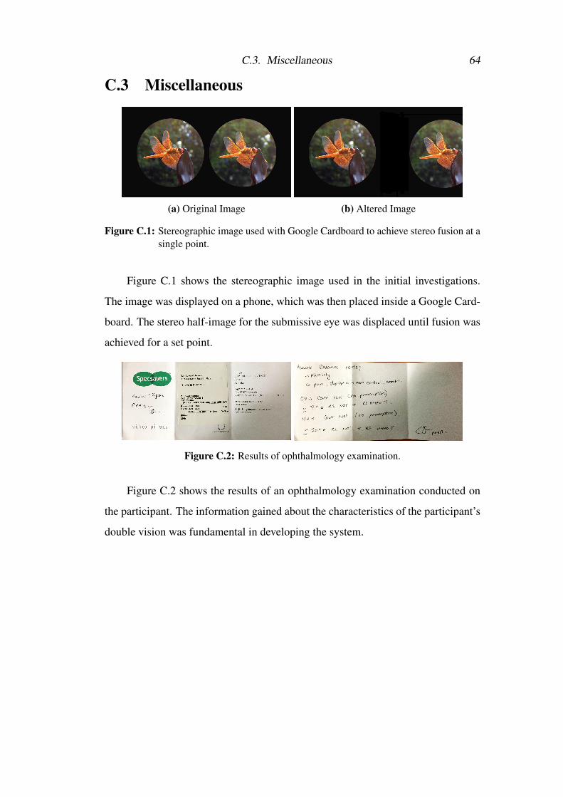
C.3. Miscellaneous 64
C.3 Miscellaneous
(a) Original Image (b) Altered Image
Figure C.1: Stereographic image used with Google Cardboard to achieve stereo fusion at asingle point.
Figure C.1 shows the stereographic image used in the initial investigations.
The image was displayed on a phone, which was then placed inside a Google Card-
board. The stereo half-image for the submissive eye was displaced until fusion was
achieved for a set point.
Figure C.2: Results of ophthalmology examination.
Figure C.2 shows the results of an ophthalmology examination conducted on
the participant. The information gained about the characteristics of the participant’s
double vision was fundamental in developing the system.

Appendix D
Evaluation Data & Results
Depth Target X Target Y Ofsset X Offset Y1.300000 0.2646484 0.4974902 0.004785989 -0.0039883241.300000 0.2300518 -0.3821618 -0.01356029 0.0039883211.300000 0.277232 -0.2458326 0.01914394 0.0031906577.001083 -0.3642431 -0.4816051 0.001248511 -0.010875173.046339 -0.1772761 0.2728384 0.03880867 -0.014436083.046339 -0.2682835 -0.2663378 0.04762036 -0.0099365163.046339 0.1056995 -0.8416095 0.04443315 -0.0101243.046339 -0.1986574 0.260119 0.04199588 -0.010686443.046339 -0.2276916 -0.1933535 0.05774442 -0.020247990.3513549 -0.172788 0.1185427 0.03694995 0.0038894720.3513549 -0.1391787 -0.2604246 0.007778938 -0.01166840.6434312 -0.2681813 -0.4631829 0.04861836 0.025281546.167243 0.336692 0.9551353 0.002798767 -0.0090959952.455079 -0.1876192 -1.89519 0.07206823 -0.01679262.455079 -0.9241664 0.2405396 0.05387625 -0.014693532.455079 0.7168546 1.673842 0.04268119 -0.012594452.455079 1.10638 -1.767422 0.0419815 0.0020990730.4863279 0.1787629 -0.2169389 0.02588859 0.011894760.4863279 0.1888159 0.379145 0.04338088 0.011894760.4863279 0.179485 -0.1829798 0.01049537 0.0097956860.4863279 -0.2070504 0.0367403 0.03498458 0.01399384
Table D.1: Snippet of data obtained from render translation experiments
Table D.1 is a snippet of the data obtained from the render translation HMD
experiment conducted. It shows the required (x,y) displacement required to align
the image of an object at a specific depth and position in the participant’s visual
field and cause fusion.
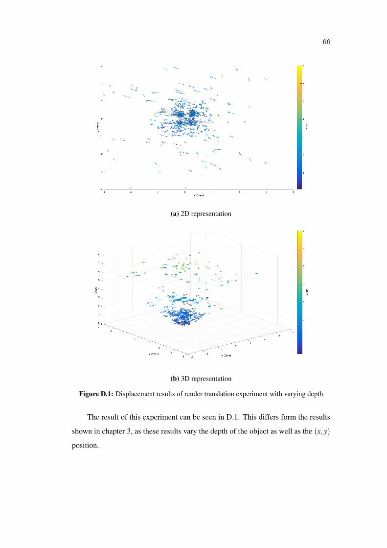
66
(a) 2D representation
(b) 3D representation
Figure D.1: Displacement results of render translation experiment with varying depth
The result of this experiment can be seen in D.1. This differs form the results
shown in chapter 3, as these results vary the depth of the object as well as the (x,y)
position.
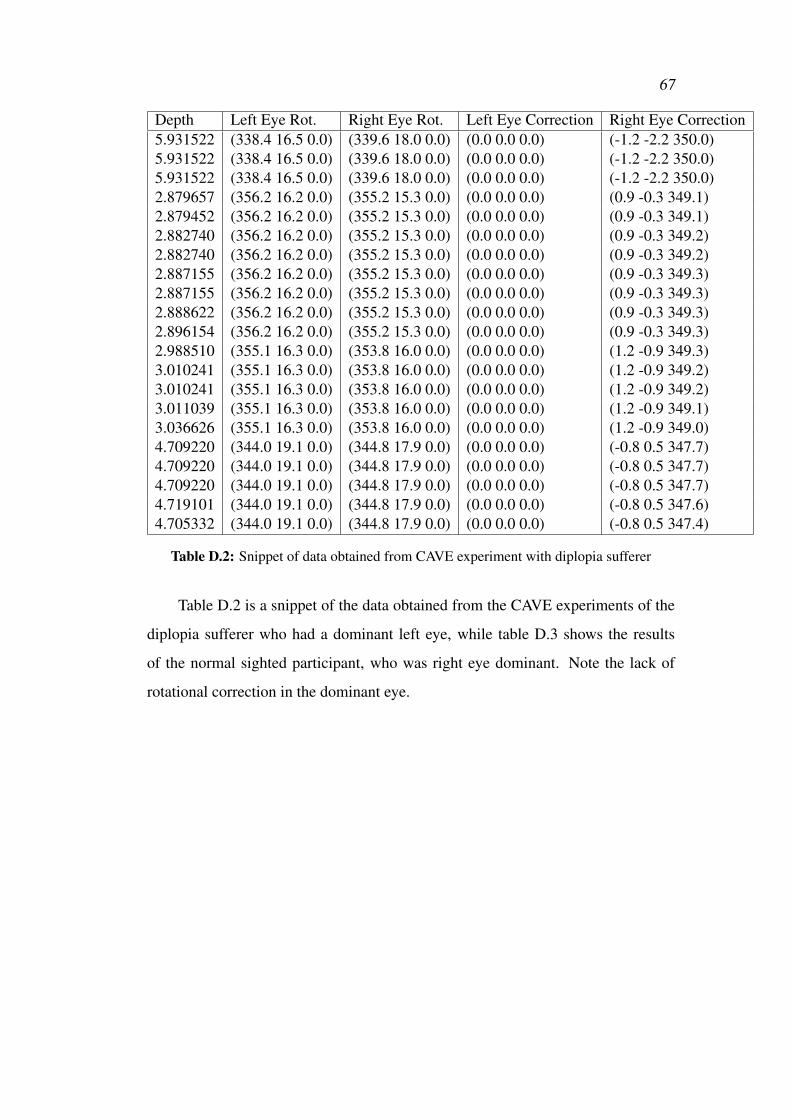
67
Depth Left Eye Rot. Right Eye Rot. Left Eye Correction Right Eye Correction5.931522 (338.4 16.5 0.0) (339.6 18.0 0.0) (0.0 0.0 0.0) (-1.2 -2.2 350.0)5.931522 (338.4 16.5 0.0) (339.6 18.0 0.0) (0.0 0.0 0.0) (-1.2 -2.2 350.0)5.931522 (338.4 16.5 0.0) (339.6 18.0 0.0) (0.0 0.0 0.0) (-1.2 -2.2 350.0)2.879657 (356.2 16.2 0.0) (355.2 15.3 0.0) (0.0 0.0 0.0) (0.9 -0.3 349.1)2.879452 (356.2 16.2 0.0) (355.2 15.3 0.0) (0.0 0.0 0.0) (0.9 -0.3 349.1)2.882740 (356.2 16.2 0.0) (355.2 15.3 0.0) (0.0 0.0 0.0) (0.9 -0.3 349.2)2.882740 (356.2 16.2 0.0) (355.2 15.3 0.0) (0.0 0.0 0.0) (0.9 -0.3 349.2)2.887155 (356.2 16.2 0.0) (355.2 15.3 0.0) (0.0 0.0 0.0) (0.9 -0.3 349.3)2.887155 (356.2 16.2 0.0) (355.2 15.3 0.0) (0.0 0.0 0.0) (0.9 -0.3 349.3)2.888622 (356.2 16.2 0.0) (355.2 15.3 0.0) (0.0 0.0 0.0) (0.9 -0.3 349.3)2.896154 (356.2 16.2 0.0) (355.2 15.3 0.0) (0.0 0.0 0.0) (0.9 -0.3 349.3)2.988510 (355.1 16.3 0.0) (353.8 16.0 0.0) (0.0 0.0 0.0) (1.2 -0.9 349.3)3.010241 (355.1 16.3 0.0) (353.8 16.0 0.0) (0.0 0.0 0.0) (1.2 -0.9 349.2)3.010241 (355.1 16.3 0.0) (353.8 16.0 0.0) (0.0 0.0 0.0) (1.2 -0.9 349.2)3.011039 (355.1 16.3 0.0) (353.8 16.0 0.0) (0.0 0.0 0.0) (1.2 -0.9 349.1)3.036626 (355.1 16.3 0.0) (353.8 16.0 0.0) (0.0 0.0 0.0) (1.2 -0.9 349.0)4.709220 (344.0 19.1 0.0) (344.8 17.9 0.0) (0.0 0.0 0.0) (-0.8 0.5 347.7)4.709220 (344.0 19.1 0.0) (344.8 17.9 0.0) (0.0 0.0 0.0) (-0.8 0.5 347.7)4.709220 (344.0 19.1 0.0) (344.8 17.9 0.0) (0.0 0.0 0.0) (-0.8 0.5 347.7)4.719101 (344.0 19.1 0.0) (344.8 17.9 0.0) (0.0 0.0 0.0) (-0.8 0.5 347.6)4.705332 (344.0 19.1 0.0) (344.8 17.9 0.0) (0.0 0.0 0.0) (-0.8 0.5 347.4)
Table D.2: Snippet of data obtained from CAVE experiment with diplopia sufferer
Table D.2 is a snippet of the data obtained from the CAVE experiments of the
diplopia sufferer who had a dominant left eye, while table D.3 shows the results
of the normal sighted participant, who was right eye dominant. Note the lack of
rotational correction in the dominant eye.

68
Depth Left Eye Rot. Right Eye Rot. Left Eye Correction Right Eye Correction1.592793 (332.4 4.5 0.0) (329.4 357.6 0.0) (-3.0 -4.3 352.8) (0.0 0.0 0.0)1.593578 (332.4 4.5 0.0) (329.4 357.6 0.0) (-3.0 -4.3 352.9) (0.0 0.0 0.0)1.593578 (332.4 4.5 0.0) (329.4 357.6 0.0) (-3.0 -4.3 352.9) (0.0 0.0 0.0)1.593578 (332.4 4.5 0.0) (329.4 357.6 0.0) (-3.0 -4.3 352.9) (0.0 0.0 0.0)4.739592 (332.4 4.5 0.0) (329.4 357.6 0.0) (-3.0 354.0 354.3) (0.0 0.0 0.0)4.739592 (332.4 4.5 0.0) (329.4 357.6 0.0) (-3.0 354.0 354.3) (0.0 0.0 0.0)4.739592 (332.4 4.5 0.0) (329.4 357.6 0.0) (-3.0 354.0 354.3) (0.0 0.0 0.0)4.765780 (332.4 4.5 0.0) (329.4 357.6 0.0) (-3.0 354.0 354.3) (0.0 0.0 0.0)4.720867 (332.8 5.3 0.0) (330.5 358.6 0.0) (-2.3 354.2 353.2) (0.0 0.0 0.0)4.738589 (332.8 5.3 0.0) (330.5 358.6 0.0) (-2.3 354.2 353.2) (0.0 0.0 0.0)4.738589 (332.8 5.3 0.0) (330.5 358.6 0.0) (-2.3 354.2 353.2) (0.0 0.0 0.0)4.738589 (332.8 5.3 0.0) (330.5 358.6 0.0) (-2.3 354.2 353.2) (0.0 0.0 0.0)1.683659 (338.9 2.6 0.0) (335.2 354.8 0.0) (-3.7 354.5355.4) (0.0 0.0 0.0)1.684112 (338.9 2.6 0.0) (335.3 354.8 0.0) (-3.6 354.5355.4) (0.0 0.0 0.0)1.682125 (338.0 2.9 0.0) (335.1 355.2 0.0) (-3.0 354.6354.6) (0.0 0.0 0.0)1.689715 (338.0 3.6 0.0) (335.4 355.9 0.0) (-2.6 354.6354.1) (0.0 0.0 0.0)1.691270 (338.4 2.9 0.0) (335.4 355.1 0.0) (-3.1 354.5354.8) (0.0 0.0 0.0)1.691270 (338.4 2.9 0.0) (335.4 355.1 0.0) (-3.1 354.5354.8) (0.0 0.0 0.0)1.690796 (338.4 2.9 0.0) (335.4 355.1 0.0) (-3.1 354.5354.8) (0.0 0.0 0.0)1.690796 (338.4 2.9 0.0) (335.4 355.1 0.0) (-3.1 354.5354.8) (0.0 0.0 0.0)
Table D.3: Snippet of data obtained from CAVE experiment with fully sighted participant

Appendix E
Project Plan & Interim Report
E.1 Project PlanStudent’s Name: Edward James
Supervisor(s) Name: Anthony Steed
Project Title: Correction of diplopia in adults with augmented reality.
E.1.1 Aims and Objectives
E.1.1.1
Aim: To determine if it is possible to correct double vision (diplopia) of a user
with a virtual environment and evaluate if the user gains stereoscopy and depth
perception.
Objectives
1. Develop software that uses a Cave Automatic Virtual Environment (CAVE)
to artificially offset a user’s eyesight for a single point of fixed position and
depth, and evaluate the change in the user’s vision in regards to stereoscopy
and depth perception.
2. Repeat the above experiment several points of differing position and depth,
and evaluate the change (if any) of the values required for correction.
3. Use the above data to develop a corrective function for differing position and
depth.
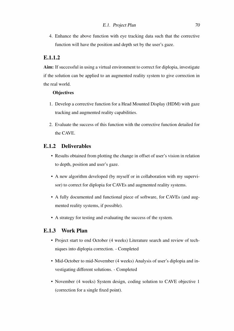
E.1. Project Plan 70
4. Enhance the above function with eye tracking data such that the corrective
function will have the position and depth set by the user’s gaze.
E.1.1.2Aim: If successful in using a virtual environment to correct for diplopia, investigate
if the solution can be applied to an augmented reality system to give correction in
the real world.
Objectives
1. Develop a corrective function for a Head Mounted Display (HDM) with gaze
tracking and augmented reality capabilities.
2. Evaluate the success of this function with the corrective function detailed for
the CAVE.
E.1.2 Deliverables
• Results obtained from plotting the change in offset of user’s vision in relation
to depth, position and user’s gaze.
• A new algorithm developed (by myself or in collaboration with my supervi-
sor) to correct for diplopia for CAVEs and augmented reality systems.
• A fully documented and functional piece of software, for CAVEs (and aug-
mented reality systems, if possible).
• A strategy for testing and evaluating the success of the system.
E.1.3 Work Plan
• Project start to end October (4 weeks) Literature search and review of tech-
niques into diplopia correction. - Completed
• Mid-October to mid-November (4 weeks) Analysis of user’s diplopia and in-
vestigating different solutions. - Completed
• November (4 weeks) System design, coding solution to CAVE objective 1
(correction for a single fixed point).

E.1. Project Plan 71
• End November to End December (4 weeks) Development of solutions for
CAVE objectives 2,3,4.
• January (4 weeks) Investigation into development of an augmented reality
system.
• Mid-January to mid-February (4 weeks) System testing and evaluation.
• Mid-February to end of March (6 weeks) Work on Final Report.
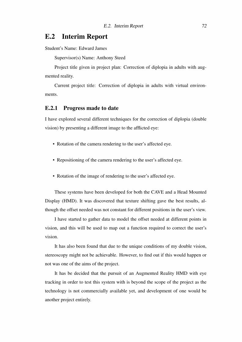
E.2. Interim Report 72
E.2 Interim ReportStudent’s Name: Edward James
Supervisor(s) Name: Anthony Steed
Project title given in project plan: Correction of diplopia in adults with aug-
mented reality.
Current project title: Correction of diplopia in adults with virtual environ-
ments.
E.2.1 Progress made to date
I have explored several different techniques for the correction of diplopia (double
vision) by presenting a different image to the afflicted eye:
• Rotation of the camera rendering to the user’s affected eye.
• Repositioning of the camera rendering to the user’s affected eye.
• Rotation of the image of rendering to the user’s affected eye.
These systems have been developed for both the CAVE and a Head Mounted
Display (HMD). It was discovered that texture shifting gave the best results, al-
though the offset needed was not constant for different positions in the user’s view.
I have started to gather data to model the offset needed at different points in
vision, and this will be used to map out a function required to correct the user’s
vision.
It has also been found that due to the unique conditions of my double vision,
stereoscopy might not be achievable. However, to find out if this would happen or
not was one of the aims of the project.
It has be decided that the pursuit of an Augmented Reality HMD with eye
tracking in order to test this system with is beyond the scope of the project as the
technology is not commercially available yet, and development of one would be
another project entirely.

E.2. Interim Report 73
E.2.2 Remaining work to be done
• Gather more data points in the HMD, including the offset needed at different
depths. - End of January
• Calculate the function required to inverse this offset. - End of January
• Investigate if a post process distortion effect can give correction for HMDs,
without the need of eye tracking. - Start of February
• Repeat the above with the CAVE system, using its eye tracking functionality.
- Mid February
• Compare the functions. - Mid February
• See if it is possible to simulate diplopia in non-sufferers and investigate if the
solution works for them. - Mid/End of February
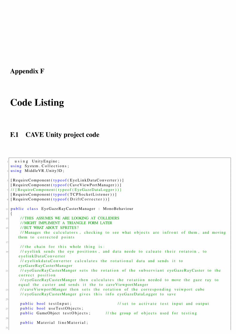
Appendix F
Code Listing
F.1 CAVE Unity project code
1 u s i n g Un i tyEng ine ;u s i n g System . C o l l e c t i o n s ;
3 u s i n g MiddleVR Unity3D ;
5 [ RequireComponent ( t y p e o f ( E y e L i n k D a t a C o n v e r t e r ) ) ][ RequireComponent ( t y p e o f ( CaveViewPortManager ) ) ]
7 / / [ RequireComponent ( t y p e o f ( EyeGazeDataLogger ) ) ][ RequireComponent ( t y p e o f ( T C P S o c k e t L i s t e n e r ) ) ]
9 [ RequireComponent ( t y p e o f ( D r i f t C o r r e c t e r ) ) ]
11 p u b l i c c l a s s EyeGazeRayCasterManager : MonoBehaviour{
13 / / THIS ASSUMES WE ARE LOOKING AT COLLIDERS/ / MIGHT IMPLIMENT A TRIANGLE FORM LATER
15 / / BUT WHAT ABOUT SPRITES?/ / Manages t h e c a l c u l a t o r s , c h e c k i n g t o s e e what o b j e c t s a r e i n f r o n t o f them , and moving
them t o c o r r e c t e d p o i n t s17
/ / t h e c h a i n f o r t h i s whole t h i n g i s :19 / / e y e l i n k s e n d s t h e eye p o s i t i o n s , and d a t a neede t o c a l u a t e t h e i r r o t a t o i n , t o
e y e l i n k D a t a C o n v e r t e r/ / e y e l i n k d a t a C o n v e r t e r c a l c u l a t e s t h e r o t a t i o n a l d a t a and s e n d s i t t o
eyeGazeRayCas terManager21 / / eyeGazeRayCasterManger s e t s t h e r o t a t i o n o f t h e s u b s e r v i a n t eyeGazeRayCas te r t o t h e
c o r r e c t p o s i t i o n/ / eyeGazeRayCasterManger t h e n c a l c u l a t e s t h e r o t a t i o n needed t o move t h e gaze r a y t o
e q u a l t h e c a s t e r and s e n d s i t t h e t o caveViewpor tManger23 / / caveViewpor tManger t h e n s e t s t h e r o t a t i o n o f t h e c o r r e s p o n d i n g v e i w p o r t cube
/ / eyeGazeRayCasterManger g i v e s t h i s i n f o eyeGazeDataLogger t o save25
p u b l i c boo l t e s t I n p u t ; / / s e t t o a c t i v a t e t e s t i n p u t and o u t p u t27 p u b l i c boo l u s e T e s t O b j e c t s ;
p u b l i c GameObject t e s t O b j e c t s ; / / t h e group of o b j e c t s used f o r t e s t i n g29
p u b l i c M a t e r i a l l i n e M a t e r i a l ;31
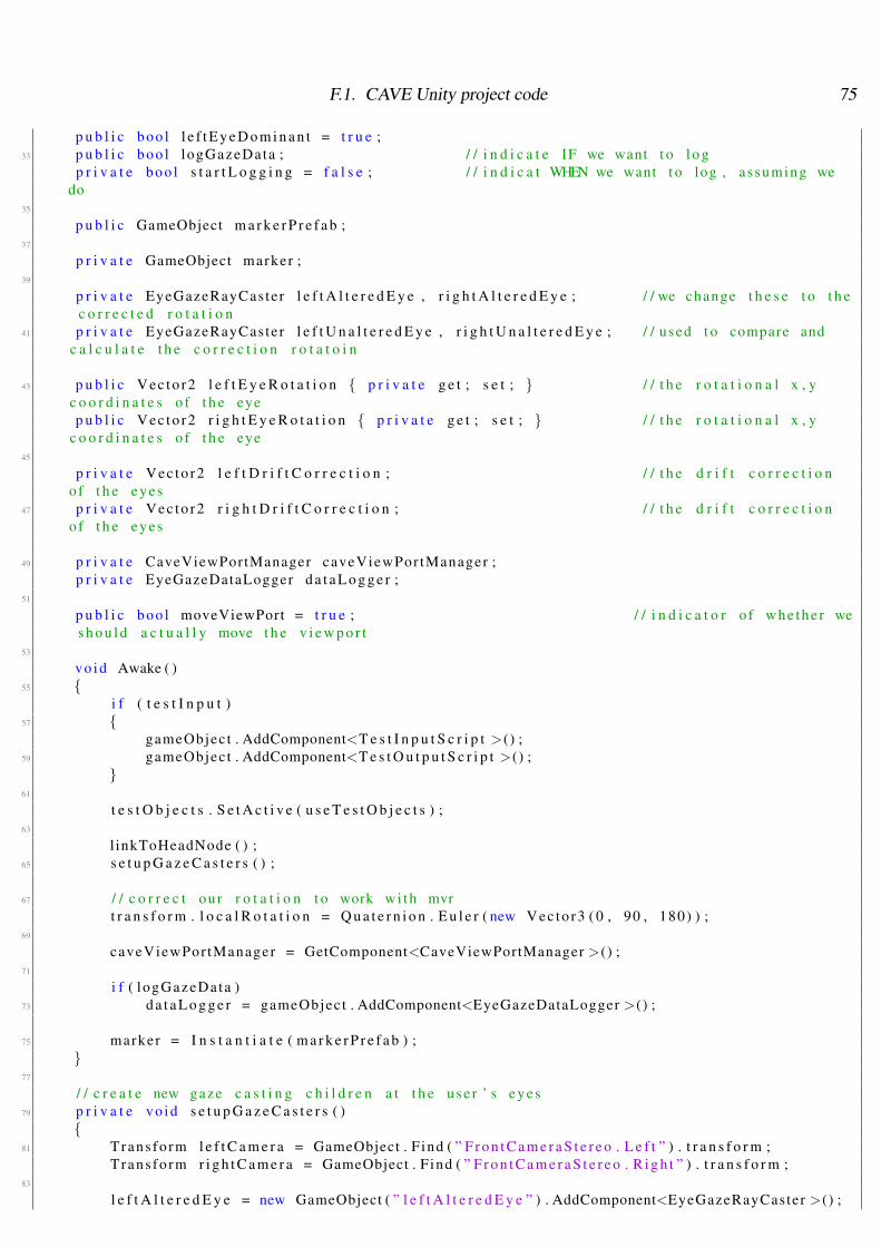
F.1. CAVE Unity project code 75
p u b l i c boo l l e f t E y e D o m i n a n t = t r u e ;33 p u b l i c boo l logGazeData ; / / i n d i c a t e IF we want t o l o g
p r i v a t e boo l s t a r t L o g g i n g = f a l s e ; / / i n d i c a t WHEN we want t o log , assuming wedo
35
p u b l i c GameObject m a r k e r P r e f a b ;37
p r i v a t e GameObject marker ;39
p r i v a t e EyeGazeRayCaster l e f t A l t e r e d E y e , r i g h t A l t e r e d E y e ; / / we change t h e s e t o t h ec o r r e c t e d r o t a t i o n
41 p r i v a t e EyeGazeRayCaster l e f t U n a l t e r e d E y e , r i g h t U n a l t e r e d E y e ; / / used t o compare andc a l c u l a t e t h e c o r r e c t i o n r o t a t o i n
43 p u b l i c Vec to r2 l e f t E y e R o t a t i o n { p r i v a t e g e t ; s e t ; } / / t h e r o t a t i o n a l x , yc o o r d i n a t e s o f t h e eyep u b l i c Vec to r2 r i g h t E y e R o t a t i o n { p r i v a t e g e t ; s e t ; } / / t h e r o t a t i o n a l x , y
c o o r d i n a t e s o f t h e eye45
p r i v a t e Vec to r2 l e f t D r i f t C o r r e c t i o n ; / / t h e d r i f t c o r r e c t i o no f t h e eyes
47 p r i v a t e Vec to r2 r i g h t D r i f t C o r r e c t i o n ; / / t h e d r i f t c o r r e c t i o no f t h e eyes
49 p r i v a t e CaveViewPortManager caveViewPor tManager ;p r i v a t e EyeGazeDataLogger d a t a L o g g e r ;
51
p u b l i c boo l moveViewPort = t r u e ; / / i n d i c a t o r o f whe the r wes h o u l d a c t u a l l y move t h e v i e w p o r t
53
vo id Awake ( )55 {
i f ( t e s t I n p u t )57 {
gameObject . AddComponent<T e s t I n p u t S c r i p t >() ;59 gameObject . AddComponent<T e s t O u t p u t S c r i p t >() ;
}61
t e s t O b j e c t s . S e t A c t i v e ( u s e T e s t O b j e c t s ) ;63
l inkToHeadNode ( ) ;65 s e t u p G a z e C a s t e r s ( ) ;
67 / / c o r r e c t our r o t a t i o n t o work wi th mvrt r a n s f o r m . l o c a l R o t a t i o n = Q u a t e r n i o n . E u l e r ( new Vec to r3 ( 0 , 90 , 180) ) ;
69
caveViewPor tManager = GetComponent<CaveViewPortManager >() ;71
i f ( logGazeData )73 d a t a L o g g e r = gameObject . AddComponent<EyeGazeDataLogger >() ;
75 marker = I n s t a n t i a t e ( m a r k e r P r e f a b ) ;}
77
/ / c r e a t e new gaze c a s t i n g c h i l d r e n a t t h e use r ’ s eyes79 p r i v a t e vo id s e t u p G a z e C a s t e r s ( )
{81 Trans fo rm l e f t C a m e r a = GameObject . F ind ( ” F r o n t C a m e r a S t e r e o . L e f t ” ) . t r a n s f o r m ;
Trans fo rm r i g h t C a m e r a = GameObject . F ind ( ” F r o n t C a m e r a S t e r e o . R i g h t ” ) . t r a n s f o r m ;83
l e f t A l t e r e d E y e = new GameObject ( ” l e f t A l t e r e d E y e ” ) . AddComponent<EyeGazeRayCaster >() ;
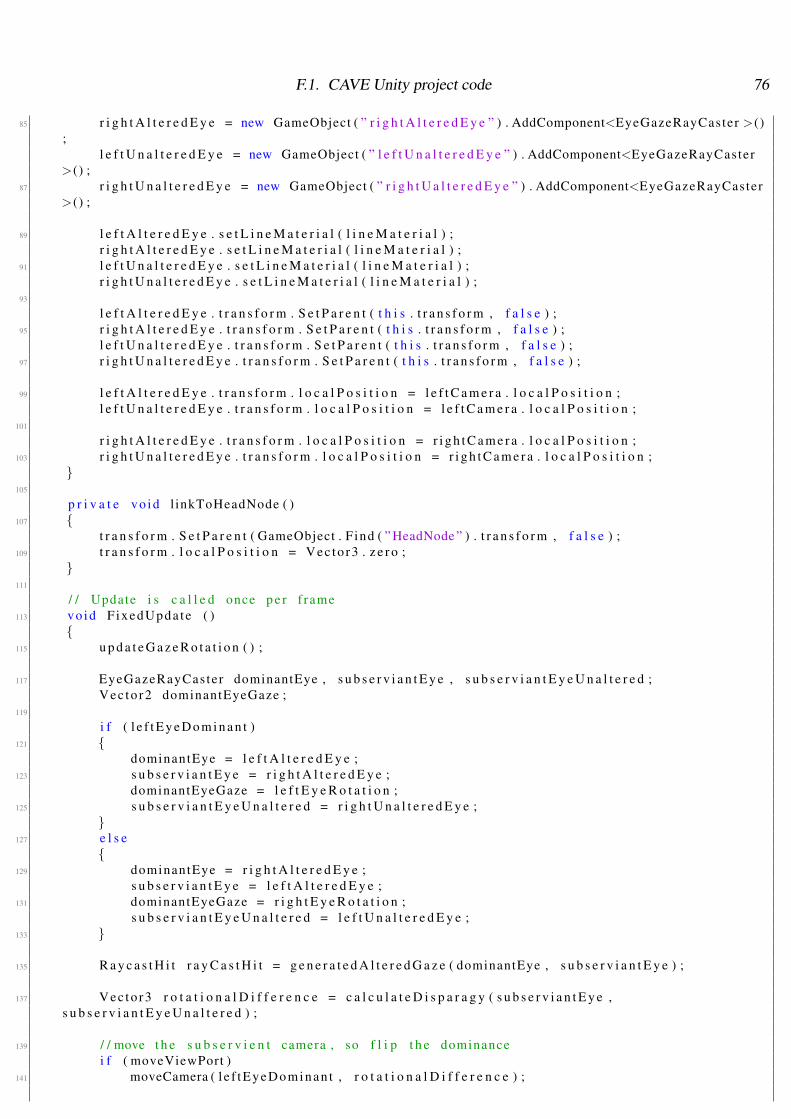
F.1. CAVE Unity project code 76
85 r i g h t A l t e r e d E y e = new GameObject ( ” r i g h t A l t e r e d E y e ” ) . AddComponent<EyeGazeRayCaster >();
l e f t U n a l t e r e d E y e = new GameObject ( ” l e f t U n a l t e r e d E y e ” ) . AddComponent<EyeGazeRayCaster>() ;
87 r i g h t U n a l t e r e d E y e = new GameObject ( ” r i g h t U a l t e r e d E y e ” ) . AddComponent<EyeGazeRayCaster>() ;
89 l e f t A l t e r e d E y e . s e t L i n e M a t e r i a l ( l i n e M a t e r i a l ) ;r i g h t A l t e r e d E y e . s e t L i n e M a t e r i a l ( l i n e M a t e r i a l ) ;
91 l e f t U n a l t e r e d E y e . s e t L i n e M a t e r i a l ( l i n e M a t e r i a l ) ;r i g h t U n a l t e r e d E y e . s e t L i n e M a t e r i a l ( l i n e M a t e r i a l ) ;
93
l e f t A l t e r e d E y e . t r a n s f o r m . S e t P a r e n t ( t h i s . t r a n s f o r m , f a l s e ) ;95 r i g h t A l t e r e d E y e . t r a n s f o r m . S e t P a r e n t ( t h i s . t r a n s f o r m , f a l s e ) ;
l e f t U n a l t e r e d E y e . t r a n s f o r m . S e t P a r e n t ( t h i s . t r a n s f o r m , f a l s e ) ;97 r i g h t U n a l t e r e d E y e . t r a n s f o r m . S e t P a r e n t ( t h i s . t r a n s f o r m , f a l s e ) ;
99 l e f t A l t e r e d E y e . t r a n s f o r m . l o c a l P o s i t i o n = l e f t C a m e r a . l o c a l P o s i t i o n ;l e f t U n a l t e r e d E y e . t r a n s f o r m . l o c a l P o s i t i o n = l e f t C a m e r a . l o c a l P o s i t i o n ;
101
r i g h t A l t e r e d E y e . t r a n s f o r m . l o c a l P o s i t i o n = r i g h t C a m e r a . l o c a l P o s i t i o n ;103 r i g h t U n a l t e r e d E y e . t r a n s f o r m . l o c a l P o s i t i o n = r i g h t C a m e r a . l o c a l P o s i t i o n ;
}105
p r i v a t e vo id l inkToHeadNode ( )107 {
t r a n s f o r m . S e t P a r e n t ( GameObject . F ind ( ” HeadNode ” ) . t r a n s f o r m , f a l s e ) ;109 t r a n s f o r m . l o c a l P o s i t i o n = Vec to r3 . z e r o ;
}111
/ / Update i s c a l l e d once p e r f rame113 vo id F ixedUpda te ( )
{115 u p d a t e G a z e R o t a t i o n ( ) ;
117 EyeGazeRayCaster dominantEye , s u b s e r v i a n t E y e , s u b s e r v i a n t E y e U n a l t e r e d ;Vec to r2 dominantEyeGaze ;
119
i f ( l e f t E y e D o m i n a n t )121 {
dominantEye = l e f t A l t e r e d E y e ;123 s u b s e r v i a n t E y e = r i g h t A l t e r e d E y e ;
dominantEyeGaze = l e f t E y e R o t a t i o n ;125 s u b s e r v i a n t E y e U n a l t e r e d = r i g h t U n a l t e r e d E y e ;
}127 e l s e
{129 dominantEye = r i g h t A l t e r e d E y e ;
s u b s e r v i a n t E y e = l e f t A l t e r e d E y e ;131 dominantEyeGaze = r i g h t E y e R o t a t i o n ;
s u b s e r v i a n t E y e U n a l t e r e d = l e f t U n a l t e r e d E y e ;133 }
135 R a y c a s t H i t r a y C a s t H i t = g e n e r a t e d A l t e r e d G a z e ( dominantEye , s u b s e r v i a n t E y e ) ;
137 Vec to r3 r o t a t i o n a l D i f f e r e n c e = c a l c u l a t e D i s p a r a g y ( s u b s e r v i a n t E y e ,s u b s e r v i a n t E y e U n a l t e r e d ) ;
139 / / move t h e s u b s e r v i e n t camera , so f l i p t h e dominancei f ( moveViewPort )
141 moveCamera ( l e f tEyeDominan t , r o t a t i o n a l D i f f e r e n c e ) ;

F.1. CAVE Unity project code 77
143 i f ( MiddleVR . VRDeviceMgr . I sWandBut tonToggled ( 2 , t r u e ) )s t a r t L o g g i n g = t r u e ;
145
i f ( logGazeData && s t a r t L o g g i n g )147 l o g D a t a ( r a y C a s t H i t . d i s t a n c e , s u b s e r v i a n t E y e . t r a n s f o r m . l o c a l R o t a t i o n ) ;
149 / / debugmarker . t r a n s f o r m . p o s i t i o n = r a y C a s t H i t . p o i n t ;
151
p r i n t O u t ( l e f t A l t e r e d E y e . t r a n s f o r m . l o c a l E u l e r A n g l e s . T o S t r i n g ( ) , r i g h t A l t e r e d E y e .t r a n s f o r m . l o c a l E u l e r A n g l e s . T o S t r i n g ( ) ) ;
153
/ / Debug code155 / / l e f t A l t e r e d E y e . debugDraw ( r a y C a s t H i t . p o i n t , r a y C a s t H i t . d i s t a n c e , Co lo r . b l u e ) ;
/ / r i g h t A l t e r e d E y e . debugDraw ( r a y C a s t H i t . p o i n t , r a y C a s t H i t . d i s t a n c e , Co lo r . r e d ) ;157 / / l e f t U n a l t e r e d E y e . debugDraw ( l e f t U n a l t e r e d E y e . t r a n s f o r m . p o s i t i o n , r a y C a s t H i t .
d i s t a n c e * 2 , Co lo r . cyan ) ;/ / r i g h t U n a l t e r e d E y e . debugDraw ( r i g h t U n a l t e r e d E y e . t r a n s f o r m . p o s i t i o n , r a y C a s t H i t .
d i s t a n c e * 2 , Co lo r . magenta ) ;159
}161
/ / s e t t h e gaze r o t a t o i n f o r a l l o f t h e r a y c a s t e r s163 p r i v a t e vo id u p d a t e G a z e R o t a t i o n ( )
{165 l e f t U n a l t e r e d E y e . t r a n s f o r m . l o c a l R o t a t i o n = Q u a t e r n i o n . E u l e r ( l e f t E y e R o t a t i o n −
l e f t D r i f t C o r r e c t i o n ) ;r i g h t U n a l t e r e d E y e . t r a n s f o r m . l o c a l R o t a t i o n = Q u a t e r n i o n . E u l e r ( r i g h t E y e R o t a t i o n −
r i g h t D r i f t C o r r e c t i o n ) ;167 l e f t A l t e r e d E y e . t r a n s f o r m . l o c a l R o t a t i o n = Q u a t e r n i o n . E u l e r ( l e f t E y e R o t a t i o n −
l e f t D r i f t C o r r e c t i o n ) ;r i g h t A l t e r e d E y e . t r a n s f o r m . l o c a l R o t a t i o n = Q u a t e r n i o n . E u l e r ( r i g h t E y e R o t a t i o n −
r i g h t D r i f t C o r r e c t i o n ) ;169 }
171 / / moves t h e a l t e r e d gaze r a y c a s t e r s t o bo th look a t t h e c o r r e c t p o i n t/ / a l s o r e t u r n s t h e R a y c a s t H i t o f t h e o b j e c t we a r e l o o k i n g a t
173 p r i v a t e R a y c a s t H i t g e n e r a t e d A l t e r e d G a z e ( EyeGazeRayCaster dominantEye , EyeGazeRayCasters u b s e r v i a n t E y e ){
175 R a y c a s t H i t d o m i n a n t R a y c a s t H i t ;
177 / / i f we h i t some th ingi f ( dominantEye . r a y C a s t ( dominantEye . t r a n s f o r m . forward , o u t d o m i n a n t R a y c a s t H i t ) )
179 {Q u a t e r n i o n p r e v i o u s R o t a t o i n = s u b s e r v i a n t E y e . t r a n s f o r m . l o c a l R o t a t i o n ;
181
/ / s e t t h e s u b s e r v i a n t eye t o look a t t h a t p o i n t183 s u b s e r v i a n t E y e . t r a n s f o r m . LookAt ( d o m i n a n t R a y c a s t H i t . p o i n t ) ;
185 R a y c a s t H i t r a y C a s t H i t ;
187 / / i f we h i t a n y t h i n gi f ( s u b s e r v i a n t E y e . r a y C a s t ( s u b s e r v i a n t E y e . t r a n s f o r m . forward , o u t r a y C a s t H i t ) )
189 / / check t o s e e i f r a y c a s t r t o w a r d s s e l e c t e d p o i n t g i v e s t h e same p o i n t (round a bou t )
i f ( Vec to r3 . SqrMagni tude ( r a y C a s t H i t . p o i n t − d o m i n a n t R a y c a s t H i t . p o i n t ) >0 .0000001 f )
191 / / and r e s e t t h e eye i f t h a t i s n ’ t t h e c a s es u b s e r v i a n t E y e . t r a n s f o r m . l o c a l R o t a t i o n = p r e v i o u s R o t a t o i n ;
193 }
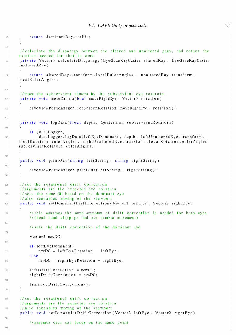
F.1. CAVE Unity project code 78
195 r e t u r n d o m i n a n t R a y c a s t H i t ;}
197
/ / c a l c u l a t e t h e d i s p a r a g y between t h e a l t e r e d and u n a l t e r e d gaze , and r e t u r n t h er o t a t i o n needed f o r t h a t t o work
199 p r i v a t e Vec to r3 c a l c u l a t e D i s p a r a g y ( EyeGazeRayCaster a l t e r e d R a y , EyeGazeRayCasteru n a l t e r e d R a y ){
201 r e t u r n a l t e r e d R a y . t r a n s f o r m . l o c a l E u l e r A n g l e s − u n a l t e r e d R a y . t r a n s f o r m .l o c a l E u l e r A n g l e s ;}
203
/ / move t h e s u b s e r v i e n t camera by t h e s u b s e r v i e n t eye r o t a t o i n205 p r i v a t e vo id moveCamera ( boo l moveRightEye , Vec to r3 r o t a t i o n )
{207 caveViewPor tManager . s e t S c r e e n R o t a t i o n ( moveRightEye , r o t a t i o n ) ;
}209
p r i v a t e vo id l o g D a t a ( f l o a t depth , Q u a t e r n i o n s u b s e r v i a n t R o t a t o i n )211 {
i f ( d a t a L o g g e r )213 d a t a L o g g e r . l o g D a t a ( l e f tEyeDominan t , depth , l e f t U n a l t e r e d E y e . t r a n s f o r m .
l o c a l R o t a t i o n . e u l e r A n g l e s , r i g h t U n a l t e r e d E y e . t r a n s f o r m . l o c a l R o t a t i o n . e u l e r A n g l e s ,s u b s e r v i a n t R o t a t o i n . e u l e r A n g l e s ) ;}
215
p u b l i c vo id p r i n t O u t ( s t r i n g l e f t S t r i n g , s t r i n g r i g h t S t r i n g )217 {
caveViewPor tManager . p r i n t O u t ( l e f t S t r i n g , r i g h t S t r i n g ) ;219 }
221 / / s e t t h e r o t a t i o n a l d r i f t c o r r e c t i o n/ / a rgumen t s a r e t h e e x p e c t e d eye r o t a t i o n
223 / / s e t s t h e same DC based on t h e dominant eye/ / a l s o r e e n a b l e s moving of t h e v i e w p o r t
225 p u b l i c vo id s e t D o m i n a n t D r i f t C o r r e c t i o n ( Vec to r2 l e f t E y e , Vec to r2 r i g h t E y e ){
227 / / t h i s assumes t h e same ammount o f d r i f t c o r r e c t i o n i s needed f o r bo th eyes/ / ( head band s l i p p a g e and n o t camera movement )
229
/ / s e t s t h e d r i f t c o r r e c t i o n o f t h e dominant eye231
Vec to r2 newDC ;233
i f ( l e f t E y e D o m i n a n t )235 newDC = l e f t E y e R o t a t i o n − l e f t E y e ;
e l s e237 newDC = r i g h t E y e R o t a t i o n − r i g h t E y e ;
239 l e f t D r i f t C o r r e c t i o n = newDC ;r i g h t D r i f t C o r r e c t i o n = newDC ;
241
f i n i s h e d D r i f t C o r r e c t i o n ( ) ;243 }
245 / / s e t t h e r o t a t i o n a l d r i f t c o r r e c t i o n/ / a rgumen t s a r e t h e e x p e c t e d eye r o t a t i o n
247 / / a l s o r e e n a b l e s moving of t h e v i e w p o r tp u b l i c vo id s e t B i n o c u l a r D r i f t C o r r e c t i o n ( Vec to r2 l e f t E y e , Vec to r2 r i g h t E y e )
249 {/ / assumes eyes can f o c u s on t h e same p o i n t
251
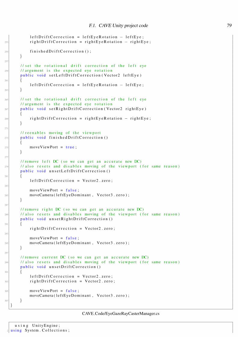
F.1. CAVE Unity project code 79
l e f t D r i f t C o r r e c t i o n = l e f t E y e R o t a t i o n − l e f t E y e ;253 r i g h t D r i f t C o r r e c t i o n = r i g h t E y e R o t a t i o n − r i g h t E y e ;
255 f i n i s h e d D r i f t C o r r e c t i o n ( ) ;}
257
/ / s e t t h e r o t a t i o n a l d r i f t c o r r e c t i o n o f t h e l e f t eye259 / / a rgument i s t h e e x p e c t e d eye r o t a t i o n
p u b l i c vo id s e t L e f t D r i f t C o r r e c t i o n ( Vec to r2 l e f t E y e )261 {
l e f t D r i f t C o r r e c t i o n = l e f t E y e R o t a t i o n − l e f t E y e ;263 }
265 / / s e t t h e r o t a t i o n a l d r i f t c o r r e c t i o n o f t h e l e f t eye/ / a rgument i s t h e e x p e c t e d eye r o t a t i o n
267 p u b l i c vo id s e t R i g h t D r i f t C o r r e c t i o n ( Vec to r2 r i g h t E y e ){
269 r i g h t D r i f t C o r r e c t i o n = r i g h t E y e R o t a t i o n − r i g h t E y e ;}
271
/ / r e e n a b l e s moving of t h e v i e w p o r t273 p u b l i c vo id f i n i s h e d D r i f t C o r r e c t i o n ( )
{275 moveViewPort = t r u e ;
}277
/ / remove l e f t DC ( so we can g e t an a c c u r a t e new DC)279 / / a l s o r e s e t s and d i s a b l e s moving of t h e v i e w p o r t ( f o r same r e a s o n )
p u b l i c vo id u n s e t L e f t D r i f t C o r r e c t i o n ( )281 {
l e f t D r i f t C o r r e c t i o n = Vec to r2 . z e r o ;283
moveViewPort = f a l s e ;285 moveCamera ( l e f tEyeDominan t , Vec to r3 . z e r o ) ;
}287
/ / remove r i g h t DC ( so we can g e t an a c c u r a t e new DC)289 / / a l s o r e s e t s and d i s a b l e s moving of t h e v i e w p o r t ( f o r same r e a s o n )
p u b l i c vo id u n s e t R i g h t D r i f t C o r r e c t i o n ( )291 {
r i g h t D r i f t C o r r e c t i o n = Vec to r2 . z e r o ;293
moveViewPort = f a l s e ;295 moveCamera ( l e f tEyeDominan t , Vec to r3 . z e r o ) ;
}297
/ / remove c u r r e n t DC ( so we can g e t an a c c u r a t e new DC)299 / / a l s o r e s e t s and d i s a b l e s moving of t h e v i e w p o r t ( f o r same r e a s o n )
p u b l i c vo id u n s e t D r i f t C o r r e c t i o n ( )301 {
l e f t D r i f t C o r r e c t i o n = Vec to r2 . z e r o ;303 r i g h t D r i f t C o r r e c t i o n = Vec to r2 . z e r o ;
305 moveViewPort = f a l s e ;moveCamera ( l e f tEyeDominan t , Vec to r3 . z e r o ) ;
307 }}
CAVE Code/EyeGazeRayCasterManager.cs
u s i n g Un i tyEng ine ;2 u s i n g System . C o l l e c t i o n s ;
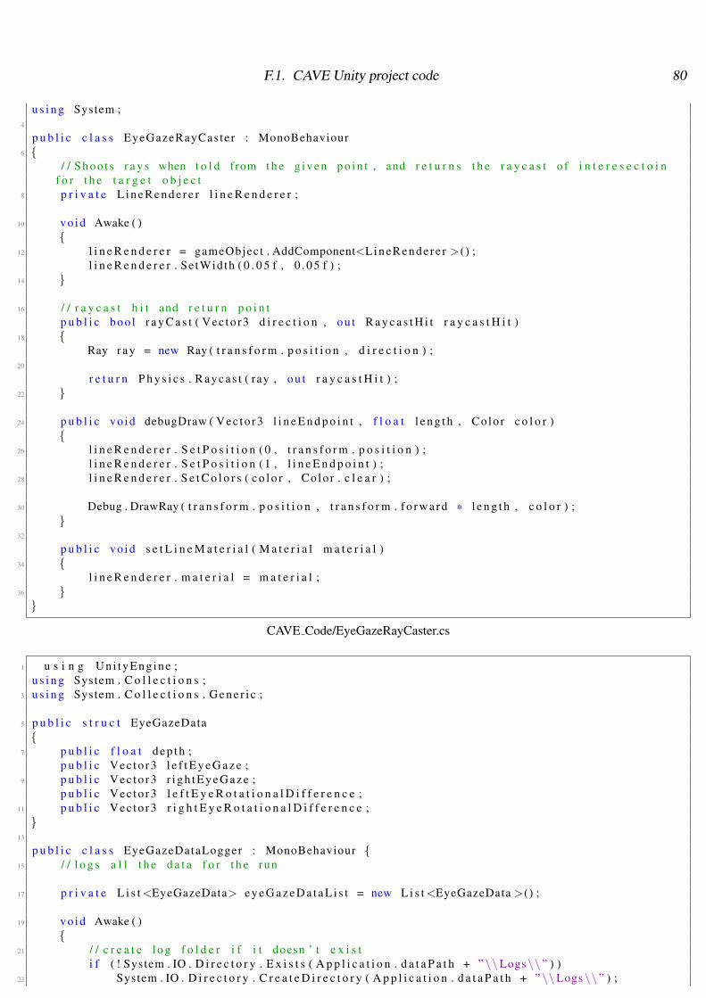
F.1. CAVE Unity project code 80
u s i n g System ;4
p u b l i c c l a s s EyeGazeRayCaster : MonoBehaviour6 {
/ / Sho o t s r a y s when t o l d from t h e g i v e n p o i n t , and r e t u r n s t h e r a y c a s t o f i n t e r e s e c t o i nf o r t h e t a r g e t o b j e c t
8 p r i v a t e L i n e R e n d e r e r l i n e R e n d e r e r ;
10 vo id Awake ( ){
12 l i n e R e n d e r e r = gameObject . AddComponent<LineRende re r >() ;l i n e R e n d e r e r . Se tWidth ( 0 . 0 5 f , 0 . 0 5 f ) ;
14 }
16 / / r a y c a s t h i t and r e t u r n p o i n tp u b l i c boo l r a y C a s t ( Vec to r3 d i r e c t i o n , o u t R a y c a s t H i t r a y c a s t H i t )
18 {Ray r a y = new Ray ( t r a n s f o r m . p o s i t i o n , d i r e c t i o n ) ;
20
r e t u r n P h y s i c s . R a y c a s t ( ray , o u t r a y c a s t H i t ) ;22 }
24 p u b l i c vo id debugDraw ( Vec to r3 l i n e E n d p o i n t , f l o a t l e n g t h , Co lo r c o l o r ){
26 l i n e R e n d e r e r . S e t P o s i t i o n ( 0 , t r a n s f o r m . p o s i t i o n ) ;l i n e R e n d e r e r . S e t P o s i t i o n ( 1 , l i n e E n d p o i n t ) ;
28 l i n e R e n d e r e r . S e t C o l o r s ( c o l o r , Co lo r . c l e a r ) ;
30 Debug . DrawRay ( t r a n s f o r m . p o s i t i o n , t r a n s f o r m . f o r w a r d * l e n g t h , c o l o r ) ;}
32
p u b l i c vo id s e t L i n e M a t e r i a l ( M a t e r i a l m a t e r i a l )34 {
l i n e R e n d e r e r . m a t e r i a l = m a t e r i a l ;36 }}
CAVE Code/EyeGazeRayCaster.cs
1 u s i n g Un i tyEng ine ;u s i n g System . C o l l e c t i o n s ;
3 u s i n g System . C o l l e c t i o n s . G e n e r i c ;
5 p u b l i c s t r u c t EyeGazeData{
7 p u b l i c f l o a t d e p t h ;p u b l i c Vec to r3 l e f t E y e G a z e ;
9 p u b l i c Vec to r3 r i g h t E y e G a z e ;p u b l i c Vec to r3 l e f t E y e R o t a t i o n a l D i f f e r e n c e ;
11 p u b l i c Vec to r3 r i g h t E y e R o t a t i o n a l D i f f e r e n c e ;}
13
p u b l i c c l a s s EyeGazeDataLogger : MonoBehaviour {15 / / l o g s a l l t h e d a t a f o r t h e run
17 p r i v a t e L i s t <EyeGazeData> e y e G a z e D a t a L i s t = new L i s t <EyeGazeData >() ;
19 vo id Awake ( ){
21 / / c r e a t e l o g f o l d e r i f i t doesn ’ t e x i s ti f ( ! System . IO . D i r e c t o r y . E x i s t s ( A p p l i c a t i o n . d a t a P a t h + ”\\Logs\\ ” ) )
23 System . IO . D i r e c t o r y . C r e a t e D i r e c t o r y ( A p p l i c a t i o n . d a t a P a t h + ”\\Logs\\ ” ) ;

F.1. CAVE Unity project code 81
}25
vo id O n A p p l i c a t i o n Q u i t ( )27 {
s a v e D a t a ( ) ;29 }
31 p r i v a t e vo id s a v e D a t a ( ){
33 / / Wr i t e t h e s t r i n g t o a f i l e .System . IO . S t r e a m W r i t e r f i l e = new System . IO . S t r e a m W r i t e r ( A p p l i c a t i o n . d a t a P a t h + ”\\
Logs\\ ” + System . DateTime . Now . ToFi leTimeUtc ( ) + ” g a z e o u t p u t . c sv ” ) ;35
f i l e . W r i t e L i n e ( ” Depth Of O b j e c t o i n , L e f t Eye R o t a t i o n , , , R i g h t Eye R o t a t i o n , , ,L e f t Eye R o t a t i o n a l C o r r e c t i o n , , , R i g h t Eye R o t a t i o n a l C o r r e c t o i n , , ” ) ;
37
f o r e a c h ( EyeGazeData eyeGazeData i n e y e G a z e D a t a L i s t )39 f i l e . W r i t e L i n e ( eyeGazeData . d e p t h . T o S t r i n g ( ) + ” , ” + eyeGazeData . l e f t E y e G a z e .
T o S t r i n g ( ) + ” , ” + eyeGazeData . r i g h t E y e G a z e . T o S t r i n g ( ) + ” , ” + eyeGazeData .l e f t E y e R o t a t i o n a l D i f f e r e n c e . T o S t r i n g ( ) + ” , ” + eyeGazeData . r i g h t E y e R o t a t i o n a l D i f f e r e n c e .T o S t r i n g ( ) ) ;
41 f i l e . C lose ( ) ;}
43
p u b l i c vo id l o g D a t a ( boo l l e f tEyeDominan t , f l o a t depth , Vec to r3 l e f t E y e G a z e , Vec to r3r igh tEyeGaze , Vec to r3 s u b s e r v i a n t A l t e r e d G a z e )
45 {/ / c a r e a t e d a gazeDa ta e n t r y and add i t o t t h e l i s t
47 EyeGazeData eyeGazeData ;Vec to r3 l e f t E y e R o t D i f , r i g h t E y e R o t D i f ;
49
i f ( l e f t E y e D o m i n a n t )51 {
l e f t E y e R o t D i f = Vec to r3 . z e r o ;53 r i g h t E y e R o t D i f = s u b s e r v i a n t A l t e r e d G a z e − r i g h t E y e G a z e ;
}55 e l s e
{57 r i g h t E y e R o t D i f = Vec to r3 . z e r o ;
l e f t E y e R o t D i f = s u b s e r v i a n t A l t e r e d G a z e − l e f t E y e G a z e ;59 }
61 eyeGazeData . d e p t h = d e p t h ;eyeGazeData . l e f t E y e G a z e = l e f t E y e G a z e ;
63 eyeGazeData . r i g h t E y e G a z e = r i g h t E y e G a z e ;eyeGazeData . l e f t E y e R o t a t i o n a l D i f f e r e n c e = l e f t E y e R o t D i f ;
65 eyeGazeData . r i g h t E y e R o t a t i o n a l D i f f e r e n c e = r i g h t E y e R o t D i f ;
67 e y e G a z e D a t a L i s t . Add ( eyeGazeData ) ;}
69 }
CAVE Code/EyeGazeDataLogger.cs
1 u s i n g Un i tyEng ine ;u s i n g MiddleVR Unity3D ;
3 u s i n g System . C o l l e c t i o n s ;
5 p u b l i c enum D r i f t C o r r e c t i o n T y p e{
7 B i n o c u l u a r ,

F.1. CAVE Unity project code 82
Binocu la rDominan t ,9 Monocular ,}
11
p u b l i c c l a s s D r i f t C o r r e c t e r : MonoBehaviour13 {
/ / show a cube when t r i g g e r i s h e l d down15 / / f i n d t h e r o t a t i o n needed t o look a t t h a t marker spawned i n f r o n t o f t h e p a l y e r
/ / and s e t t h e d r i f t c o r r e c i t o n f o r EyeGazeRayCastManger17
p u b l i c D r i f t C o r r e c t i o n T y p e c o r r r e c t i o n T y p e ;19
p u b l i c GameObject d r i f t C o r r e c t i o n P r e f a b ;21
p r i v a t e GameObject dcMarker ;23 p r i v a t e GameObject lef tDCEye , r ightDCEye ; / / used t o f i n d t h e eye r o t a t i o n
needed t o look a t t h e DC markerp u b l i c Vec to r2 spawnPo in t = Vec to r2 . z e r o ; / / i n f r o n t o f t h e use r , l o c a l s p a c e
25
p r i v a t e boo l c o r r e c t i n g L e f t E y e = t r u e ; / / used f o r DC when monocular27 p r i v a t e boo l d c C l e a r e d = f a l s e ;
29 p r i v a t e i n t l e f tEyeMask , r igh tEyeMask ;
31 p r i v a t e EyeGazeRayCasterManager c a s t e r M a n a g e r ;
33 vo id S t a r t ( ){
35 c a s t e r M a n a g e r = GetComponent<EyeGazeRayCasterManager >() ;setupDCEyes ( ) ;
37 s e t u p C u l l i n g M a s k s ( ) ;}
39
/ / c r e a t e new gaze c a s t i n g c h i l d r e n a t t h e use r ’ s eyes41 p r i v a t e vo id setupDCEyes ( )
{43 Trans fo rm l e f t C a m e r a = GameObject . F ind ( ” F r o n t C a m e r a S t e r e o . L e f t ” ) . t r a n s f o r m ;
Trans fo rm r i g h t C a m e r a = GameObject . F ind ( ” F r o n t C a m e r a S t e r e o . R i g h t ” ) . t r a n s f o r m ;45
l e f tDCEye = new GameObject ( ” le f tDCEye ” ) ;47 r ightDCEye = new GameObject ( ” r ightDCEye ” ) ;
49 l e f tDCEye . t r a n s f o r m . S e t P a r e n t ( t h i s . t r a n s f o r m , f a l s e ) ;r ightDCEye . t r a n s f o r m . S e t P a r e n t ( t h i s . t r a n s f o r m , f a l s e ) ;
51
l e f tDCEye . t r a n s f o r m . l o c a l P o s i t i o n = l e f t C a m e r a . l o c a l P o s i t i o n ;53 r ightDCEye . t r a n s f o r m . l o c a l P o s i t i o n = r i g h t C a m e r a . l o c a l P o s i t i o n ;
55 / / and spawn t h e DC markerdcMarker = I n s t a n t i a t e ( d r i f t C o r r e c t i o n P r e f a b , Vec to r3 . ze ro , Q u a t e r n i o n . i d e n t i t y ) a s
GameObject ;57 dcMarker . t r a n s f o r m . S e t P a r e n t ( t r a n s f o r m , f a l s e ) ;
/ / needs t o be t r a n s f o r m . r i g h t i n cave ( u n l e s s i s e t o r i e n t a t i o n )59 / / o r use m i d d l e v r c o n v e r t e r
dcMarker . t r a n s f o r m . l o c a l P o s i t i o n = ( Vec to r3 ) spawnPo in t + t r a n s f o r m . r i g h t ;61 dcMarker . S e t A c t i v e ( f a l s e ) ;
}63
/ / a t t e m p t s t o g e t t h e c u l l i n g masks f o r each eye65 / / and a t t e m p s t o f i n d t h e cameras and s e t s t h e i r c u l l i n g mask
p r i v a t e vo id s e t u p C u l l i n g M a s k s ( )67 {
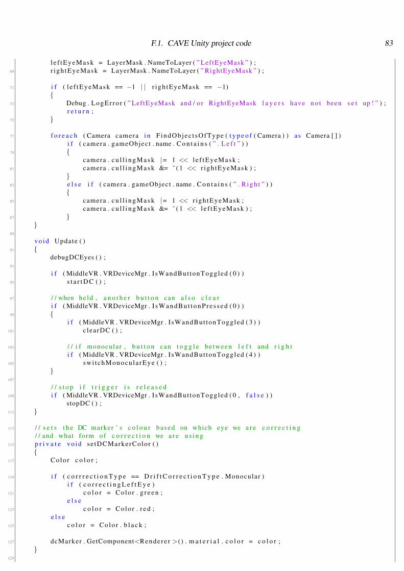
F.1. CAVE Unity project code 83
l e f tEyeMask = LayerMask . NameToLayer ( ” LeftEyeMask ” ) ;69 r igh tEyeMask = LayerMask . NameToLayer ( ” RightEyeMask ” ) ;
71 i f ( l e f tEyeMask == −1 | | r igh tEyeMask == −1){
73 Debug . LogEr ro r ( ” LeftEyeMask and / o r RightEyeMask l a y e r s have n o t been s e t up ! ” ) ;r e t u r n ;
75 }
77 f o r e a c h ( Camera camera i n F indObjec t sOfType ( t y p e o f ( Camera ) ) a s Camera [ ] )i f ( camera . gameObject . name . C o n t a i n s ( ” . L e f t ” ) )
79 {camera . c u l l i n g M a s k |= 1 << l e f tEyeMask ;
81 camera . c u l l i n g M a s k &= ˜ ( 1 << r igh tEyeMask ) ;}
83 e l s e i f ( camera . gameObject . name . C o n t a i n s ( ” . R i g h t ” ) ){
85 camera . c u l l i n g M a s k |= 1 << r igh tEyeMask ;camera . c u l l i n g M a s k &= ˜ ( 1 << l e f tEyeMask ) ;
87 }}
89
vo id Update ( )91 {
debugDCEyes ( ) ;93
i f ( MiddleVR . VRDeviceMgr . I sWandBut tonToggled ( 0 ) )95 s t a r t D C ( ) ;
97 / / when he ld , a n o t h e r b u t t o n can a l s o c l e a ri f ( MiddleVR . VRDeviceMgr . I s Wa n dB u t t on Pr e s s ed ( 0 ) )
99 {i f ( MiddleVR . VRDeviceMgr . I sWandBut tonToggled ( 3 ) )
101 c learDC ( ) ;
103 / / i f monocular , b u t t o n can t o g g l e between l e f t and r i g h ti f ( MiddleVR . VRDeviceMgr . I sWandBut tonToggled ( 4 ) )
105 swi tchMonocu la rEye ( ) ;}
107
/ / s t o p i f t r i g g e r i s r e l e a s e d109 i f ( MiddleVR . VRDeviceMgr . I sWandBut tonToggled ( 0 , f a l s e ) )
stopDC ( ) ;111 }
113 / / s e t s t h e DC marker ’ s c o l o u r based on which eye we a r e c o r r e c t i n g/ / and what form of c o r r e c t i o n we a r e u s i n g
115 p r i v a t e vo id se tDCMarkerColor ( ){
117 Colo r c o l o r ;
119 i f ( c o r r r e c t i o n T y p e == D r i f t C o r r e c t i o n T y p e . Monocular )i f ( c o r r e c t i n g L e f t E y e )
121 c o l o r = Colo r . g r e e n ;e l s e
123 c o l o r = Colo r . r e d ;e l s e
125 c o l o r = Colo r . b l a c k ;
127 dcMarker . GetComponent<Rendere r >() . m a t e r i a l . c o l o r = c o l o r ;}
129

F.1. CAVE Unity project code 84
/ / s e t s t h e DC marker ’ s l a y e r based on which eye which eye we a r e c o r r e c t i n g131 / / and what form of c o r r e c i t o n we a r e u s i n g
p r i v a t e vo id se tDCMarkerLayer ( )133 {
i n t l a y e r ;135
i f ( c o r r r e c t i o n T y p e == D r i f t C o r r e c t i o n T y p e . Monocular )137 i f ( c o r r e c t i n g L e f t E y e )
l a y e r = l e f tEyeMask ;139 e l s e
l a y e r = r igh tEyeMask ;141 e l s e
l a y e r = LayerMask . NameToLayer ( ” D e f a u l t ” ) ;143
dcMarker . l a y e r = l a y e r ;145 f o r e a c h ( Trans fo rm c h i l d i n dcMarker . t r a n s f o r m )
c h i l d . gameObject . l a y e r = l a y e r ;147 }
149 / / make DC eyes look a t t h e markerp r i v a t e vo id s e t D C E y e R o t a t i o n s ( )
151 {l e f tDCEye . t r a n s f o r m . LookAt ( dcMarker . t r a n s f o r m . p o s i t i o n ) ;
153 r ightDCEye . t r a n s f o r m . LookAt ( dcMarker . t r a n s f o r m . p o s i t i o n ) ;}
155
p r i v a t e vo id debugDCEyes ( )157 {
Debug . DrawRay ( le f tDCEye . t r a n s f o r m . p o s i t i o n , le f tDCEye . t r a n s f o r m . f o r w a r d * 50 , Co lo r .ye l l ow ) ;
159 Debug . DrawRay ( r ightDCEye . t r a n s f o r m . p o s i t i o n , r ightDCEye . t r a n s f o r m . f o r w a r d * 50 ,Co lo r . y e l l ow ) ;}
161
/ / t o g g l e s t h e c u r r e n t monocula r eye f o r DC163 / / and s e t s t h e DC v a l u e f o r t h e o t h e r eye
p u b l i c vo id swi tchMonocu la rEye ( )165 {
i f ( c o r r r e c t i o n T y p e != D r i f t C o r r e c t i o n T y p e . Monocular )167 r e t u r n ;
169 setDC ( ) ;c o r r e c t i n g L e f t E y e = ! c o r r e c t i n g L e f t E y e ;
171 se tDCMarkerColor ( ) ;se tDCMarkerLayer ( ) ;
173 }
175 p u b l i c vo id s t a r t D C ( ){
177 / / a c t i v a t e marker and s e t DC t o z e r o f o r c o r r e c t i o ndcMarker . S e t A c t i v e ( t r u e ) ;
179 se tDCMarkerColor ( ) ;se tDCMarkerLayer ( ) ;
181
c a s t e r M a n a g e r . u n s e t D r i f t C o r r e c t i o n ( ) ;183
s e t D C E y e R o t a t i o n s ( ) ;185 d c C l e a r e d = f a l s e ;
}187
/ / u p d a t e s t h e v a l u e s f o r d r i f t c o r r e c t i o n189 p u b l i c vo id setDC ( )

F.1. CAVE Unity project code 85
{191 s w i t c h ( c o r r r e c t i o n T y p e )
{193 c a s e D r i f t C o r r e c t i o n T y p e . B i n o c u l u a r :
c a s t e r M a n a g e r . s e t B i n o c u l a r D r i f t C o r r e c t i o n ( le f tDCEye . t r a n s f o r m .l o c a l E u l e r A n g l e s , r ightDCEye . t r a n s f o r m . l o c a l R o t a t i o n . e u l e r A n g l e s ) ;
195 b r e a k ;c a s e D r i f t C o r r e c t i o n T y p e . B in ocu l a r Dom ina n t :
197 c a s t e r M a n a g e r . s e t D o m i n a n t D r i f t C o r r e c t i o n ( le f tDCEye . t r a n s f o r m .l o c a l E u l e r A n g l e s , r ightDCEye . t r a n s f o r m . l o c a l R o t a t i o n . e u l e r A n g l e s ) ;
b r e a k ;199 c a s e D r i f t C o r r e c t i o n T y p e . Monocular :
i f ( c o r r e c t i n g L e f t E y e )201 c a s t e r M a n a g e r . s e t L e f t D r i f t C o r r e c t i o n ( le f tDCEye . t r a n s f o r m .
l o c a l E u l e r A n g l e s ) ;e l s e
203 c a s t e r M a n a g e r . s e t R i g h t D r i f t C o r r e c t i o n ( r ightDCEye . t r a n s f o r m .l o c a l E u l e r A n g l e s ) ;
b r e a k ;205 }
}207
p u b l i c vo id stopDC ( )209 {
/ / u p d a t e v a l u e s i f n o t c a n c l e d211 i f ( ! d c C l e a r e d )
setDC ( ) ;213
/ / d e a c t i v a t e marker215 dcMarker . S e t A c t i v e ( f a l s e ) ;
c a s t e r M a n a g e r . f i n i s h e d D r i f t C o r r e c t i o n ( ) ;217 }
219 p u b l i c vo id c learDC ( ){
221 / / s t o p DC and t h e n c l e a r d r i f td c C l e a r e d = t r u e ;
223 stopDC ( ) ;}
225 }
CAVE Code/DriftCorrecter.cs
1 u s i n g Un i tyEng ine ;u s i n g System . T h r e a d i n g ;
3 u s i n g System . Net . S o c k e t s ;u s i n g System . IO ;
5 u s i n g System . C o l l e c t i o n s . G e n e r i c ;
7 / / Using code from h t t p : / / answer s . u n i t y 3 d . com / q u e s t i o n s / 1 2 3 2 9 / s e r v e r−t cp−network−problem .h tml
9 p u b l i c c l a s s T C P S o c k e t L i s t e n e r : MonoBehaviour{
11 p u b l i c s t r i n g i P A d d r e s s = ” 1 9 2 . 1 6 8 . 2 . 6 7 ” ; / / ” 1 2 8 . 1 6 . 6 . 1 1 2 ” ;p u b l i c i n t p o r t = 13000 ;
13
p r i v a t e E y e L i n k D a t a C o n v e r t e r d a t a C o n v e r t e r ;15 p r i v a t e boo l mRunning ;
17 s t r i n g msg = ” ” ;Thread mThread ;

F.1. CAVE Unity project code 86
19 T c p L i s t e n e r t c p L i s t e n e r = n u l l ;
21 s t r i n g [ ] subData = new s t r i n g [ 0 ] ;
23 vo id S t a r t ( ){
25 mRunning = t r u e ;T h r e a d S t a r t t s = new T h r e a d S t a r t ( SayHel lo ) ;
27 mThread = new Thread ( t s ) ;mThread . S t a r t ( ) ;
29 p r i n t ( ” Thread done . . . ” ) ;}
31
vo id Awake ( )33 {
d a t a C o n v e r t e r = GetComponent<EyeLinkDa taConver t e r >() ;35 }
37 p u b l i c vo id s t o p L i s t e n i n g ( ){
39 mRunning = f a l s e ;}
41
vo id SayHel lo ( )43 {
t c p L i s t e n e r = new T c p L i s t e n e r ( System . Net . IPAddres s . P a r s e ( i P A d d r e s s ) , p o r t ) ;45 t c p L i s t e n e r . S t a r t ( ) ;
p r i n t ( ” S e r v e r S t a r t ” ) ;47 w h i l e ( mRunning )
{49 / / check i f new c o n n e c t i o n s a r e pending , i f not , be n i c e and s l e e p 100ms
i f ( ! t c p L i s t e n e r . Pend ing ( ) )51 {
p r i n t ( ” s l e e p i n g ” ) ;53 Thread . S l e e p ( 1 0 0 ) ;
}55 e l s e
{57 T c p C l i e n t c l i e n t = t c p L i s t e n e r . A c c e p t T c p C l i e n t ( ) ;
NetworkStream ns = c l i e n t . GetS t ream ( ) ;59 St reamReader r e a d e r = new St reamReader ( ns ) ;
61 ns = c l i e n t . GetS t ream ( ) ;
63 do{
65 msg = r e a d e r . ReadLine ( ) ;ns . F l u s h ( ) ;
67
/ / s e t subData , so t h a t i t can be p a s s e d i n u p d a t e69 subData = msg . S p l i t ( ’ , ’ ) ;
} w h i l e ( msg != ” f i n ” ) ;71 r e a d e r . C lose ( ) ;
c l i e n t . C lose ( ) ;73 }
}75 }
77 vo id O n A p p l i c a t i o n Q u i t ( ){
79 / / s t o p l i s t e n i n g t h r e a ds t o p L i s t e n i n g ( ) ;
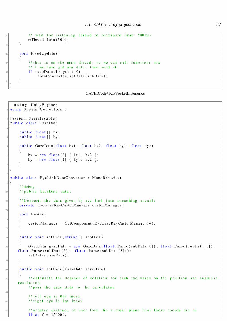
F.1. CAVE Unity project code 87
81 / / w a i t f p r l i s t e n i n g t h r e a d t o t e r m i n a t e ( max . 500ms )mThread . J o i n ( 5 0 0 ) ;
83 }
85 vo id F ixedUpda te ( ){
87 / / t h i s i s on t h e main t h r e a d , so we can c a l l f u n c i t o n s now/ / i f we have g o t new da ta , t h e n send i t
89 i f ( subData . Length > 0)d a t a C o n v e r t e r . s e t D a t a ( subData ) ;
91 }}
CAVE Code/TCPSocketListener.cs
u s i n g Un i tyEng ine ;2 u s i n g System . C o l l e c t i o n s ;
4 [ System . S e r i a l i z a b l e ]p u b l i c c l a s s GazeData
6 {p u b l i c f l o a t [ ] hx ;
8 p u b l i c f l o a t [ ] hy ;
10 p u b l i c GazeData ( f l o a t hx1 , f l o a t hx2 , f l o a t hy1 , f l o a t hy2 ){
12 hx = new f l o a t [ 2 ] { hx1 , hx2 } ;hy = new f l o a t [ 2 ] { hy1 , hy2 } ;
14 }}
16
p u b l i c c l a s s E y e L i n k D a t a C o n v e r t e r : MonoBehaviour18 {
/ / debug20 / / p u b l i c GazeData d a t a ;
22 / / C o n v e r t s t h e d a t a g i v e n by eye l i n k i n t o some th ing u s e a b l ep r i v a t e EyeGazeRayCasterManager c a s t e r M a n a g e r ;
24
vo id Awake ( )26 {
c a s t e r M a n a g e r = GetComponent<EyeGazeRayCasterManager >() ;28 }
30 p u b l i c vo id s e t D a t a ( s t r i n g [ ] subData ){
32 GazeData gazeDa ta = new GazeData ( f l o a t . P a r s e ( subData [ 0 ] ) , f l o a t . P a r s e ( subData [ 1 ] ) ,f l o a t . P a r s e ( subData [ 2 ] ) , f l o a t . P a r s e ( subData [ 3 ] ) ) ;
s e t D a t a ( gazeDa ta ) ;34 }
36 p u b l i c vo id s e t D a t a ( GazeData gazeDa ta ){
38 / / c a l c u l a t e t h e d e g r e e s o f r o t a t i o n f o r each eye based on t h e p o s i t i o n and a n g u l a a rr e s o l u t i o n
/ / p a s s t h e gaze d a t a t o t h e c a l c u l a t o r40
/ / l e f t eye i s 0 t h i n d e x42 / / r i g h t eye i s 1 s t i n d e x
44 / / a r b e t r y d i s t a n c e o f u s e r from t h e v i r t u a l p l a n e t h a t t h e s e c o o r d s a r e onf l o a t f = 15000 f ;

F.1. CAVE Unity project code 88
46
/ / r e f e r e n c e p o i n t we a r e compar ing t h e r o t a t i o n s t o ( use 0 ,0 f o r t h e sake o f t e s t i n g)
48 f l o a t x0 = 0 , y0 = 0 ;
50 f l o a t x1 = gazeDa ta . hx [ 0 ] ;f l o a t y1 = gazeDa ta . hy [ 0 ] ;
52 f l o a t x2 = gazeDa ta . hx [ 1 ] ;f l o a t y2 = gazeDa ta . hy [ 1 ] ;
54
f l o a t l e f t X = Mathf . Rad2Deg * Mathf . Atan ( x1 / f ) ;56 f l o a t l e f t Y = Mathf . Rad2Deg * Mathf . Atan ( y1 / f ) ;
58 / / do t h e same f o r t h e r i g h t eyef l o a t r i g h t X = Mathf . Rad2Deg * Mathf . Atan ( x2 / f ) ;
60 f l o a t r i g h t Y = Mathf . Rad2Deg * Mathf . Atan ( y2 / f ) ;
62 i f ( c a s t e r M a n a g e r ){
64 / / need t o f l i p t h e numbers round as we a r e s e n d i n g a n g l e s a round t h e t h e s e a x i s( r o t a t i n g a round t h e y a x i s p o i n t s on t h e x )
c a s t e r M a n a g e r . l e f t E y e R o t a t i o n = new Vec to r2 ( l e f t Y , l e f t X ) ;66 c a s t e r M a n a g e r . r i g h t E y e R o t a t i o n = new Vec to r2 ( r i gh tY , r i g h t X ) ;
}68 }}
CAVE Code/EyeLinkDataConverter.cs
1 u s i n g Un i tyEng ine ;u s i n g System . C o l l e c t i o n s ;
3
p u b l i c c l a s s CaveViewPortManager : MonoBehaviour5 {
/ / s e t s up t h e v i e w p o r t s / s c r e e n s o f middleVR so t h e v i e w p o r t s from bo th eyes can be s p l i t7
p u b l i c boo l debug { g e t ; s e t ; } / / i f s e t , we use t e s t O u t p u t9 p r i v a t e T e s t O u t p u t S c r i p t t e s t O u t p u t ;
p r i v a t e F o v e a S c r e e n S h i f t e r s c r e e n S h i f t e r ;11
vo id S t a r t ( )13 {
s c r e e n S h i f t e r = GameObject . F ind ( ” S h i f t e r ” ) . GetComponent<F o v e a S c r e e n S h i f t e r >() ;15 t e s t O u t p u t = GetComponent<T e s t O u t p u t S c r i p t >() ;
}17
p u b l i c vo id s e t S c r e e n R o t a t i o n ( boo l moveRightViewPort , Vec to r3 r o t a t i o n )19 {
i f ( debug )21 t e s t O u t p u t . t e s t O u t p u t R o t a t i o n ( moveRightViewPort , r o t a t i o n ) ;
e l s e23 s h i f t e r R o t a t i o n ( moveRightViewPort , r o t a t i o n ) ;
}25
p r i v a t e vo id s h i f t e r R o t a t i o n ( boo l moveRightViewPort , Vec to r3 r o t a t i o n )27 {
i f ( moveRightViewPor t )29 / / move t h e r i g h t v e i w p o r t
s c r e e n S h i f t e r . a p p l y R o t a t i o n ( Vec to r3 . ze ro , r o t a t i o n ) ;31 e l s e
/ / move t h e l e f t33 s c r e e n S h i f t e r . a p p l y R o t a t i o n ( r o t a t i o n , Vec to r3 . z e r o ) ;
F.1. CAVE Unity project code 89
}35
p u b l i c vo id p r i n t O u t ( s t r i n g l e f t E y e , s t r i n g r i g h t E y e )37 {
s c r e e n S h i f t e r . p r i n t O u t ( l e f t E y e , r i g h t E y e ) ;39 }}
CAVE Code/CaveViewPortManager.cs
u s i n g Un i tyEng ine ;2 u s i n g MiddleVR Unity3D ;
u s i n g System . C o l l e c t i o n s ;4
p u b l i c c l a s s F o v e a S c r e e n S h i f t e r : MonoBehaviour {6
p r i v a t e vrNode3D l e f t S c r e e n P a r e n t , r i g h t S c r e e n P a r e n t ;8
TextMesh l e f t T e x t , r i g h t T e x t ;10
vo id Awake ( )12 {
GameObject l tm = new GameObject ( ” L e f t Text Mesh” ) ;14 GameObject r tm = new GameObject ( ” R i g h t Text Mesh” ) ;
l tm . t r a n s f o r m . S e t P a r e n t ( t r a n s f o r m , f a l s e ) ;16 r tm . t r a n s f o r m . S e t P a r e n t ( t r a n s f o r m , f a l s e ) ;
r tm . t r a n s f o r m . l o c a l P o s i t i o n = Vec to r3 . up* 2 ;18
l e f t T e x t = l tm . AddComponent<TextMesh >() ;20 r i g h t T e x t = r tm . AddComponent<TextMesh >() ;
22 l e f t T e x t . c o l o r = Colo r . g r e e n ;r i g h t T e x t . c o l o r = Colo r . r e d ;
24
makeNewScreens ( ) ;26 }
28 p r i v a t e vo id makeNewScreens ( ){
30 v a r d i s p l a y M g r = MiddleVR . VRDisplayMgr ;
32 / / make a new s e t o f s c r e e n s/ / a s w e l l a s rename s c r e e n s t o L e f t C a m e r a S c r e e n s
34 l e f t S c r e e n P a r e n t = d i s p l a y M g r . GetNode ( ” S c r e e n s ” ) ;l e f t S c r e e n P a r e n t . SetName ( ” L e f t C a m e r a S c r e e n s ” ) ;
36
r i g h t S c r e e n P a r e n t = d i s p l a y M g r . Crea teNode ( ” R igh tCameraSc reens ” ) ;38 r i g h t S c r e e n P a r e n t . S e t P a r e n t ( l e f t S c r e e n P a r e n t . G e t P a r e n t ( ) ) ;
r i g h t S c r e e n P a r e n t . S e t P o s i t i o n L o c a l ( l e f t S c r e e n P a r e n t . G e t P o s i t i o n L o c a l ( ) ) ;40
/ / For each vrCameraS te reo , make a new s c r e e n f o r t h e r i g h t eye42 f o r ( u i n t i = 0 , iEnd = d i s p l a y M g r . GetCamerasNb ( ) ; i < iEnd ; ++ i )
{44 vrCamera cam = d i s p l a y M g r . GetCameraByIndex ( i ) ;
i f ( cam . IsA ( ” CameraS te reo ” ) )46 {
v r C a m e r a S t e r e o s te reoCam = d i s p l a y M g r . GetCameraSte reoById ( cam . Ge t Id ( ) ) ;48
v r S c r e e n l e f t S c r e e n = s te reoCam . GetCameraLef t ( ) . Ge tSc reen ( ) ;50 v r S c r e e n r i g h t S c r e e n = d i s p l a y M g r . C r e a t e S c r e e n ( l e f t S c r e e n . GetName ( ) ) ;
52 r i g h t S c r e e n . S e t P a r e n t ( r i g h t S c r e e n P a r e n t ) ;

F.1. CAVE Unity project code 90
r i g h t S c r e e n . S e t H e i g h t ( l e f t S c r e e n . Ge tHe igh t ( ) ) ;54 r i g h t S c r e e n . Se tWidth ( l e f t S c r e e n . GetWidth ( ) ) ;
r i g h t S c r e e n . S e t F i l t e r e d ( l e f t S c r e e n . I s F i l t e r e d ( ) ) ;56 r i g h t S c r e e n . S e t T r a c k e r ( l e f t S c r e e n . G e t T r a c k e r ( ) ) ;
r i g h t S c r e e n . S e t P o s i t i o n W o r l d ( l e f t S c r e e n . G e t P o s i t i o n W o r l d ( ) ) ;58 r i g h t S c r e e n . S e t O r i e n t a t i o n W o r l d ( l e f t S c r e e n . G e t O r i e n t a t i o n W o r l d ( ) ) ;
60 s te reoCam . GetCameraRight ( ) . S e t S c r e e n ( r i g h t S c r e e n ) ;}
62 }}
64
p u b l i c vo id a p p l y R o t a t i o n ( Vec to r3 l e f t F o v e a R o t , Vec to r3 r i g h t F o v e a R o t )66 {
/ / D i s p l a y t h e v a l u e s68 l e f t T e x t . t e x t = ”<s i z e =10>Rot : ” + l e f t F o v e a R o t + ”</ s i z e >” ;
r i g h t T e x t . t e x t = ”<s i z e =10>Rot : ” + r i g h t F o v e a R o t + ”</ s i z e >” ;70
r o t a t e S c r e e n ( l e f t S c r e e n P a r e n t , l e f t F o v e a R o t ) ;72 r o t a t e S c r e e n ( r i g h t S c r e e n P a r e n t , r i g h t F o v e a R o t ) ;
}74
p r i v a t e vo id r o t a t e S c r e e n ( vrNode3D s c r e e n P a r e n t , Vec to r3 a n g l e s )76 {
/ / remove z componant ( r o l l )78 a n g l e s . z = 0 ;
s c r e e n P a r e n t . S e t O r i e n t a t i o n L o c a l ( MVRTools . FromUnity ( Q u a t e r n i o n . E u l e r ( a n g l e s ) ) ) ;80 / / s c r e e n P a r e n t . S e t R o l l L o c a l ( a n g l e s . x ) ;
/ / s c r e e n P a r e n t . SetYawLocal ( a n g l e s . y ) ;82 / / s c r e e n P a r e n t . S e t P i t c h L o c a l ( a n g l e s . z ) ;
}84
p u b l i c vo id p r i n t O u t ( s t r i n g l e f t E y e , s t r i n g r i g h t E y e )86 {
i f ( l e f t T e x t )88 {
l e f t T e x t . t e x t = ”<s i z e =10>Rot : ” + l e f t E y e + ”</ s i z e >” ;90 r i g h t T e x t . t e x t = ”<s i z e =10>Rot : ” + r i g h t E y e + ”</ s i z e >” ;
}92 }}
CAVE Code/FoveaScreenShifter.cs
1 u s i n g Un i tyEng ine ;u s i n g System . C o l l e c t i o n s ;
3
p u b l i c c l a s s R i g h t E y e S h i f t e r : MonoBehaviour5 {
7 p r i v a t e f l o a t i n c r e m e n t = 0 .001 f ;p r i v a t e f l o a t i n c r e m e n t F i d e l i t y = 0 .0001 f ;
9
p r i v a t e f l o a t o r i g i n a l X D i s t ;11 p r i v a t e f l o a t o r i g i n a l i n c r e m e n t ;
13 p r i v a t e f l o a t x D i s t ;p r i v a t e f l o a t y D i s t ;
15
p r i v a t e f l o a t r o l l ;17 p r i v a t e f l o a t yaw ;

F.1. CAVE Unity project code 91
19 p r i v a t e boo l wantToRese t = f a l s e ;
21 i n t f r a m e C o u n t e r = 2 0 ;v rQua t q u a t ;
23
p r i v a t e boo l b e g i n = f a l s e ;25
vo id S t a r t ( )27 {
o r i g i n a l i n c r e m e n t = i n c r e m e n t ;29 v a r d i s p l a y M g r = MiddleVR . VRDisplayMgr ;
31 makeNewScreens ( ) ;Debug . Log ( ” g o t h e r e ! ” ) ;
33
b e g i n = t r u e ;35 }
37 vo id O n A p p l i c a t i o n Q u i t ( ){
39 r e s e t ( ) ;}
41
p r i v a t e vo id r e s e t ( )43 {
wantToRese t = f a l s e ;45 x D i s t = o r i g i n a l X D i s t ;
y D i s t = 0 ;47 yaw = 0 ;
r o l l = 0 ;49 i n c r e m e n t = o r i g i n a l i n c r e m e n t ;
}51
vo id Update ( )53 {
i f ( ! b e g i n )55 r e t u r n ;
57 vrKeyboard keyboard = MiddleVR . VRDeviceMgr . GetKeyboard ( ) ;
59 / / Apply new t r a n s f o r mi f ( keyboard != n u l l )
61 {/ / Hold down W t o a c t i v a t e x , y move
63 i f ( keyboard . I s K e y P r e s s e d ( MiddleVR .VRK W) ){
65 i f ( keyboard . I s K e y P r e s s e d ( MiddleVR . VRK RIGHT) )x D i s t += i n c r e m e n t ;
67 i f ( keyboard . I s K e y P r e s s e d ( MiddleVR . VRK LEFT ) )x D i s t −= i n c r e m e n t ;
69 i f ( keyboard . I s K e y P r e s s e d ( MiddleVR . VRK UP) )y D i s t += i n c r e m e n t ;
71 i f ( keyboard . I s K e y P r e s s e d ( MiddleVR .VRK DOWN) )y D i s t −= i n c r e m e n t ;
73 }/ / Hold down E t o a c t i v a t e y , z r o t a t i o n
75 i f ( keyboard . I s K e y P r e s s e d ( MiddleVR . VRK E) ){
77 i f ( keyboard . I s K e y P r e s s e d ( MiddleVR . VRK RIGHT) )r o l l += i n c r e m e n t ;
79 i f ( keyboard . I s K e y P r e s s e d ( MiddleVR . VRK LEFT ) )r o l l −= i n c r e m e n t ;

F.1. CAVE Unity project code 92
81 i f ( keyboard . I s K e y P r e s s e d ( MiddleVR . VRK UP) )yaw += i n c r e m e n t ;
83 i f ( keyboard . I s K e y P r e s s e d ( MiddleVR .VRK DOWN) )yaw −= i n c r e m e n t ;
85 }/ / P r e s s R t o r e s e t
87 i f ( keyboard . I sKeyToggled ( MiddleVR . VRK R) ){
89 i f ( wantToRese t )r e s e t ( ) ;
91 e l s ewantToRese t = t r u e ;
93 }/ / P r e s s + t o i n c r e a s e movement amount
95 i f ( keyboard . I sKeyToggled ( MiddleVR . VRK EQUALS) ){
97 i n t magn i tude = 1 ;i f ( keyboard . I s K e y P r e s s e d ( MiddleVR . VRK LSHIFT ) )
99 magni tude = 1 0 ;i n c r e m e n t += ( i n c r e m e n t F i d e l i t y * magn i tude ) ;
101 } / / P r e s s − t o i n c r e a s e movement amounti f ( keyboard . I sKeyToggled ( MiddleVR . VRK MINUS) )
103 {i n t magn i tude = 1 ;
105 i f ( keyboard . I s K e y P r e s s e d ( MiddleVR . VRK LSHIFT ) )magn i tude = 1 0 ;
107 i n c r e m e n t −= ( i n c r e m e n t F i d e l i t y * magn i tude ) ;i f ( i n c r e m e n t < 0)
109 i n c r e m e n t = 0 ;}
111 }
113 / / D i s p l a y t h e v a l u e ss t r i n g t e x t = ”<s i z e =20>Pos : ( ” + x D i s t + ” , ” + y D i s t + ” , 0 ) </ s i z e >\nRot : ( 0 , ” +
r o l l + ” , ” + yaw + ” ) \n<s i z e =10>Adjus tmen t : ” + i n c r e m e n t + ”</ s i z e >” ;115
GetComponent<TextMesh >() . t e x t = t e x t ;117
p r i n t ( t e x t ) ;119
a p p l y O f f s e t ( ) ;121 }
123 p r i v a t e vo id makeNewScreens ( ){
125 v a r d i s p l a y M g r = MiddleVR . VRDisplayMgr ;
127 / / For each vrCameraS te reo , make a new s c r e e n f o r t h e r i g h t eyef o r ( u i n t i = 0 , iEnd = d i s p l a y M g r . GetCamerasNb ( ) ; i < iEnd ; ++ i )
129 {vrCamera cam = d i s p l a y M g r . GetCameraByIndex ( i ) ;
131 i f ( cam . IsA ( ” CameraS te reo ” ) ){
133 v r C a m e r a S t e r e o s te reoCam = d i s p l a y M g r . GetCameraSte reoById ( cam . Ge t Id ( ) ) ;
135 v r S c r e e n l e f t S c r e e n = s te reoCam . GetCameraLef t ( ) . Ge tSc reen ( ) ;v r S c r e e n r i g h t S c r e e n = d i s p l a y M g r . C r e a t e S c r e e n ( l e f t S c r e e n . GetName ( ) + ” r i g h t
” ) ;137 l e f t S c r e e n . SetName ( l e f t S c r e e n . GetName ( ) + ” l e f t ” ) ;
139 r i g h t S c r e e n . S e t P a r e n t ( l e f t S c r e e n . G e t P a r e n t ( ) ) ;r i g h t S c r e e n . S e t H e i g h t ( l e f t S c r e e n . Ge tHe igh t ( ) ) ;

F.1. CAVE Unity project code 93
141 r i g h t S c r e e n . Se tWidth ( l e f t S c r e e n . GetWidth ( ) ) ;r i g h t S c r e e n . S e t F i l t e r e d ( l e f t S c r e e n . I s F i l t e r e d ( ) ) ;
143 r i g h t S c r e e n . S e t T r a c k e r ( l e f t S c r e e n . G e t T r a c k e r ( ) ) ;r i g h t S c r e e n . S e t P o s i t i o n W o r l d ( l e f t S c r e e n . G e t P o s i t i o n W o r l d ( ) ) ;
145 r i g h t S c r e e n . S e t O r i e n t a t i o n W o r l d ( l e f t S c r e e n . G e t O r i e n t a t i o n W o r l d ( ) ) ;
147 s te reoCam . GetCameraRight ( ) . S e t S c r e e n ( r i g h t S c r e e n ) ;}
149 }}
151
p r i v a t e vo id a p p l y O f f s e t ( )153 {
v a r d i s p l a y M g r = MiddleVR . VRDisplayMgr ;155
/ / For each vrCameraS te reo , a p p l y t h e new t r a n s f o r m m a t r i x t o r i g h t cameras s c r e e n157 f o r ( u i n t i = 0 , iEnd = d i s p l a y M g r . GetCamerasNb ( ) ; i < iEnd ; ++ i )
{159 vrCamera cam = d i s p l a y M g r . GetCameraByIndex ( i ) ;
i f ( cam . IsA ( ” CameraS te reo ” ) )161 {
v r C a m e r a S t e r e o s te reoCam = d i s p l a y M g r . GetCameraSte reoById ( cam . Ge t Id ( ) ) ;163
vrVec3 pos = s te reoCam . GetCameraRight ( ) . Ge tSc reen ( ) . G e t P o s i t i o n L o c a l ( ) ;165 pos . SetX ( pos . x ( ) + x D i s t ) ;
pos . SetY ( pos . y ( ) + y D i s t ) ;167 s te reoCam . GetCameraRight ( ) . Ge tSc reen ( ) . S e t P o s i t i o n L o c a l ( pos ) ;
}169 }
}171 }
CAVE Code/RightEyeShifter.cs
1 u s i n g Un i tyEng ine ;u s i n g MiddleVR Unity3D ;
3 u s i n g System . C o l l e c t i o n s ;
5 p u b l i c c l a s s S h i f t e r D e b u g O u t p u t : MonoBehaviour {
7 p r i v a t e vrNode3D l e f t S c r e e n P a r e n t , r i g h t S c r e e n P a r e n t ;
9 p r i v a t e Trans fo rm l e f t S c r e e n O u t p u t , r i g h t S c r e e n O u t p u t ;
11
/ / Use t h i s f o r i n i t i a l i z a t i o n13 vo id S t a r t ( )
{15 l e f t S c r e e n O u t p u t = GameObject . F ind ( ” L e f t C a m e r a S c r e e n s ” ) . t r a n s f o r m ;
r i g h t S c r e e n O u t p u t = GameObject . F ind ( ” R igh tCameraSc reens ” ) . t r a n s f o r m ;17
v a r d i s p l a y M g r = MiddleVR . VRDisplayMgr ;19
/ / g e t t h e s c r e e n nodes21 l e f t S c r e e n P a r e n t = d i s p l a y M g r . GetNode ( ” L e f t C a m e r a S c r e e n s ” ) ;
r i g h t S c r e e n P a r e n t = d i s p l a y M g r . GetNode ( ” R igh tCameraSc reens ” ) ;23 }
25 / / Update i s c a l l e d once p e r f ramevo id Update ( )
27 {l e f t S c r e e n O u t p u t . t r a n s f o r m . l o c a l R o t a t i o n = MVRTools . ToUnity ( l e f t S c r e e n P a r e n t .

F.1. CAVE Unity project code 94
G e t O r i e n t a t i o n L o c a l ( ) ) ;29 r i g h t S c r e e n O u t p u t . t r a n s f o r m . l o c a l R o t a t i o n = MVRTools . ToUnity ( r i g h t S c r e e n P a r e n t .
G e t O r i e n t a t i o n L o c a l ( ) ) ;}
31 }
CAVE Code/ShifterDebugOutput.cs
1 u s i n g Un i tyEng ine ;u s i n g System . C o l l e c t i o n s ;
3
p u b l i c c l a s s T e s t I n p u t S c r i p t : MonoBehaviour {5 / / s c r i p t t h a t mimics eye i n p u t and m i d d l e v r i n p u t
7 p u b l i c f l o a t movementSpeed = 0 . 1 f ;p u b l i c f l o a t i n c r e a s e S p e e d = 10 f ;
9
p r i v a t e Trans fo rm headNode ;11
p r i v a t e f l o a t min = −30000 , max = 30000 ;13 p r i v a t e E y e L i n k D a t a C o n v e r t e r d a t a C o n v e r t e r ;
p r i v a t e D r i f t C o r r e c t e r d r i f t C o r r e c t e r ;15
p u b l i c f l o a t l e f t X , l e f t Y , r i gh tX , r i g h t Y ;17
p r i v a t e boo l t r i g g e r P r e s s e d = f a l s e ;19
/ / Use t h i s f o r i n i t i a l i z a t i o n21 vo id S t a r t ( )
{23 d a t a C o n v e r t e r = GetComponent<EyeLinkDa taConver t e r >() ;
d r i f t C o r r e c t e r = GetComponent<D r i f t C o r r e c t e r >() ;25 headNode = GameObject . F ind ( ” HeadNode ” ) . t r a n s f o r m ;
}27
/ / Update i s c a l l e d once p e r f rame29 vo id Update ( )
{31 h a n d l e I n p u t ( ) ;
sendEyeData ( ) ;33 }
35 p r i v a t e vo id h a n d l e I n p u t ( ){
37 / / i f l e f t t r i g g e r i s he ld , t h e n d r i f t c o r r e c ti f ( I n p u t . GetAxis ( ” L e f t T r i g g e r ” ) > 0)
39 {i f ( ! t r i g g e r P r e s s e d )
41 {t r i g g e r P r e s s e d = t r u e ;
43 d r i f t C o r r e c t e r . s t a r t D C ( ) ;}
45
/ / p r e s s i n g A t o g g l e s between DC eyes ( i f we a r e monocula r )47 i f ( I n p u t . GetButtonDown ( ” F i r e 1 ” ) )
d r i f t C o r r e c t e r . swi t chMonocu la rEye ( ) ;49
/ / p r e s s i n g B c l e a r s DC51 i f ( I n p u t . GetButtonDown ( ” F i r e 2 ” ) )
d r i f t C o r r e c t e r . c learDC ( ) ;53 }
e l s e i f ( t r i g g e r P r e s s e d )
F.1. CAVE Unity project code 95
55 {t r i g g e r P r e s s e d = f a l s e ;
57 d r i f t C o r r e c t e r . stopDC ( ) ;}
59
f l o a t newValue ;61
/ / i f r i g h t t r i g g e r i s h e l d down t h e n c o n t r o l l eyes63 i f ( I n p u t . GetAxis ( ” R i g h t T r i g g e r ” ) > 0)
{65 newValue = I n p u t . GetAxis ( ” H o r i z o n t a l ” ) * i n c r e a s e S p e e d + l e f t X ;
i f ( newValue > min && newValue < max )67 l e f t X = newValue ;
newValue = −I n p u t . GetAxis ( ” V e r t i c a l ” ) * i n c r e a s e S p e e d + l e f t Y ;69 i f ( newValue > min && newValue < max )
l e f t Y = newValue ;71
newValue = I n p u t . GetAxis ( ” R i g h t S t i c k H o r i z o n t a l ” ) * i n c r e a s e S p e e d + r i g h t X ;73 i f ( newValue > min && newValue < max )
r i g h t X = newValue ;75 newValue = −I n p u t . GetAxis ( ” R i g h t S t i c k V e r t i c a l ” ) * i n c r e a s e S p e e d + r i g h t Y ;
i f ( newValue > min && newValue < max )77 r i g h t Y = newValue ;
}79 / / e l s e c o n t r o l l head movement and r o t a t i o n
e l s e81 {
Vec to r3 newPos = t r a n s f o r m . f o r w a r d * I n p u t . GetAxis ( ” V e r t i c a l ” ) * movementSpeed +t r a n s f o r m . r i g h t * I n p u t . GetAxis ( ” H o r i z o n t a l ” ) * movementSpeed ;
83 newPos . y = 0 ;
85 headNode . t r a n s f o r m . l o c a l P o s i t i o n += newPos ;
87 / / s e p e r a t e o u t t h e h o r i z o n t a l and v e r t i c a l r o t a t o i n ( so we g e t n i ce , f p s s t i l ll o o k i n g )
t r a n s f o r m . Rota teAround ( t r a n s f o r m . p o s i t i o n , t r a n s f o r m . r i g h t , −I n p u t . GetAxis ( ”R i g h t S t i c k V e r t i c a l ” ) ) ;
89 headNode . t r a n s f o r m . R o t a t e ( headNode . t r a n s f o r m . up , I n p u t . GetAxis ( ” R i g h t S t i c kH o r i z o n t a l ” ) ) ;
}91 }
93 p r i v a t e vo id sendEyeData ( ){
95 s t r i n g [ ] a r g s = { l e f t X . T o S t r i n g ( ) , r i g h t X . T o S t r i n g ( ) , l e f t Y . T o S t r i n g ( ) , r i g h t Y .T o S t r i n g ( ) } ;
d a t a C o n v e r t e r . s e t D a t a ( a r g s ) ;97 }}
CAVE Code/TestInputScript.cs
u s i n g Un i tyEng ine ;2 u s i n g System . C o l l e c t i o n s ;
4 p u b l i c c l a s s T e s t O u t p u t S c r i p t : MonoBehaviour {/ / H i j a c k s c a l l s t o f o v e a s c r e e n s h i f t e r t o s e e t h e e f f e c t s when n o t i n t h e cave
6 / / c o n f i g e u r e s v i ewpor tmange r t o send r o t a t i o n s h e r e
8 p r i v a t e CaveViewPortManager v iewpor tManager ;
10 p r i v a t e Trans fo rm l e f t S c r e e n P a r e n t , r i g h t S c r e e n P a r e n t ;

F.2. Eye tracker data forwarding code 96
12 / / Use t h i s f o r i n i t i a l i z a t i o nvo id S t a r t ( )
14 {v iewpor tManager = GetComponent<CaveViewPortManager >() ;
16 v iewpor tManager . debug = t r u e ;
18 l e f t S c r e e n P a r e n t = GameObject . F ind ( ” L e f t C a m e r a S c r e e n s ” ) . t r a n s f o r m ;r i g h t S c r e e n P a r e n t = GameObject . F ind ( ” R igh tCameraSc reens ” ) . t r a n s f o r m ;
20 }
22 p u b l i c vo id t e s t O u t p u t R o t a t i o n ( boo l moveRightViewPort , Vec to r3 r o t a t i o n ){
24 i f ( moveRightViewPor t )/ / move t h e r i g h t v e i w p o r t
26 a p p l y R o t a t i o n ( Vec to r3 . ze ro , r o t a t i o n ) ;e l s e
28 / / move t h e l e f ta p p l y R o t a t i o n ( r o t a t i o n , Vec to r3 . z e r o ) ;
30 }
32 p r i v a t e vo id a p p l y R o t a t i o n ( Vec to r3 l e f t F o v e a R o t , Vec to r3 r i g h t F o v e a R o t ){
34 r o t a t e S c r e e n ( l e f t S c r e e n P a r e n t , l e f t F o v e a R o t ) ;r o t a t e S c r e e n ( r i g h t S c r e e n P a r e n t , r i g h t F o v e a R o t ) ;
36 }
38 p r i v a t e vo id r o t a t e S c r e e n ( Trans fo rm s c r e e n P a r e n t , Vec to r3 r o t a t i o n ){
40 s c r e e n P a r e n t . l o c a l E u l e r A n g l e s = r o t a t i o n ;}
42 }
CAVE Code/TestOutputScript.cs
F.2 Eye tracker data forwarding code# i n c l u d e <s t d i o . h>
2 # i n c l u d e <c o r e e x p t . h># i n c l u d e <Windows . h>
4 # u s i n g <System . d l l >
6 u s i n g namespace System ;u s i n g namespace System : : Text ;
8 u s i n g namespace System : : IO ;u s i n g namespace System : : Net ;
10 u s i n g namespace System : : Net : : S o c k e t s ;
12 # d e f i n e DURATION 20000 / / 20 s e c o n d s
14 S t r i n g ˆ g e n e r a t e S t r i n g ( f l o a t hx1 , f l o a t hx2 , f l o a t hy1 , f l o a t hy2 ){
16 S t r i n g ˆ message = ” ” ;message += hx1 . T o S t r i n g ( ) + ” , ” + hx2 . T o S t r i n g ( ) + ” , ” + hy1 . T o S t r i n g ( ) + ” , ” + hy2 .
T o S t r i n g ( ) + ”\n ” ;18 r e t u r n message ;}
20
i n t main ( i n t a rgc , c h a r ** a rgv )22 {
S t r i n g ˆ i P A d d r e s s = ” 1 2 8 . 1 6 . 6 . 1 1 2 ” ; / / ” 1 9 2 . 1 6 8 . 2 . 6 7 ”24 i n t p o r t = 13000 ;

F.2. Eye tracker data forwarding code 97
26 T c p C l i e n t ˆ c l i e n t ;NetworkStream ˆ s t r e a m ;
28
t r y30 {
/ / C r e a t e a T c p C l i e n t .32 / / Note , f o r t h i s c l i e n t t o work you need t o have a TcpSe rve r
/ / c o n n e c t e d t o t h e same a d d r e s s a s s p e c i f i e d by t h e s e r v e r , p o r t34 / / c o m b i n a t i o n .
36 Conso le : : W r i t e L i n e ( ” A t t e m p t i n g t o c o n n e c t t o EyeLink . . . ” ) ;c l i e n t = gcnew T c p C l i e n t ( iPAddress , p o r t ) ;
38 s t r e a m = c l i e n t −>GetSt ream ( ) ;
40 / / Get a c l i e n t s t r e a m f o r r e a d i n g and w r i t i n g ./ / S t ream s t r e a m = c l i e n t −>GetSt ream ( ) ;
42
}44 c a t c h ( Argumen tNu l lExcep t ion ˆ e )
{46 Conso le : : W r i t e L i n e ( ” Argumen tNu l lExcep t ion : {0} ” , e ) ;
48 r e t u r n −1;}
50 c a t c h ( S o c k e t E x c e p t i o n ˆ e ){
52 Conso le : : W r i t e L i n e ( ” S o c k e t E x c e p t i o n : {0} ” , e ) ;
54 r e t u r n −1;}
56
i f ( o p e n e y e l i n k c o n n e c t i o n ( 0 ) != 0 ) / / c o n n e c t t o t h e t r a c k e r58 {
p r i n t f ( ” F a i l e d t o c o n n e c t t o t r a c k e r \n ” ) ;60 r e t u r n 0 ;
}62
e y e c m d p r i n t f ( ” l i n k s a m p l e d a t a = LEFT , RIGHT , HREF” ) ; / / t e l l t r a c k e r t o send d a t a ove rt h e l i n k
64 e y e c m d p r i n t f ( ” b i n o c u l a r e n a b l e d =YES” ) ; / / e n a b l e b i n o c u l a ri f ( s t a r t r e c o r d i n g ( 1 , 1 , 1 , 1 ) != 0 )
66 {p r i n t f ( ” f a i l e d t o s t a r t r e c o r d i n g \n ” ) ;
68 r e t u r n −1;}
70
S t r i n g ˆ message ;72 FSAMPLE sample ;
w h i l e ( ! ( GetAsyncKeySta te (VK SPACE) & 0 x8000 ) )74 {
i f ( e y e l i n k n e w e s t f l o a t s a m p l e (& sample ) > 0) / / g e t t h e newes t sample76 {
message = g e n e r a t e S t r i n g ( sample . hx [ 0 ] , sample . hx [ 1 ] , sample . hy [ 0 ] , sample . hy [ 1 ] ) ; / /form t h e gaze d a t a
78
/ / T r a n s l a t e t h e p a s s e d message i n t o ASCII and s t o r e i t a s a Byte a r r a y .80 a r r a y<Byte >ˆ d a t a = Text : : Encoding : : ASCII−>GetBytes ( message ) ;
/ / Send t h e message t o t h e c o n n e c t e d TcpSe rve r .82 s t ream−>Wri te ( da t a , 0 , da t a−>Length ) ;
84 / / p r i n t f (”% s ” , message ) ;

F.3. HMD Unity project code 98
}86 }
88 / / C lose t h e c o n n e c t i o nmessage = ” f i n \n ” ;
90
/ / T r a n s l a t e t h e p a s s e d message i n t o ASCII and s t o r e i t a s a Byte a r r a y .92 a r r a y<Byte >ˆ d a t a = Text : : Encoding : : ASCII−>GetBytes ( message ) ;
/ / Send t h e message t o t h e c o n n e c t e d TcpSe rve r .94 s t ream−>Wri te ( da t a , 0 , da t a−>Length ) ;
96 c l i e n t −>Close ( ) ;
98 s t o p r e c o r d i n g ( ) ; / / s t o p r e c o r d i n gc l o s e e y e l i n k c o n n e c t i o n ( ) ; / / d i s c o n n e c t from t r a c k e r
100 r e t u r n 1 ;}
EyeLink Code/simpleexample.cpp
F.3 HMD Unity project code1 u s i n g Un i tyEng ine ;
u s i n g System . C o l l e c t i o n s ;3
p u b l i c c l a s s CameraManger : MonoBehaviour {5 / / s e t s t h e c o r r e c t fov f o r each r e n d e r i n g camera
7 p u b l i c Camera r e f e r e n c e C a m e r a ;p u b l i c Camera l e f t R e n d e r C a m e r a , r i g h t R e n d e r C a m e r a ;
9
p r i v a t e s t a t i c CameraManger i n s t a n c e ;11
p u b l i c s t a t i c CameraManger I n s t a n c e13 {
g e t15 {
/ / I f i n s t a n c e hasn ’ t been s e t ye t , we g rab i t from t h e s c e n e !17 / / Th i s w i l l on ly happen t h e f i r s t t ime t h i s r e f e r e n c e i s used .
i f ( i n s t a n c e == n u l l )19 i n s t a n c e = GameObject . F indObjec tOfType<CameraManger >() ;
r e t u r n i n s t a n c e ;21 }
}23
p r i v a t e f l o a t i n i t i a l F O V ;25
vo id S t a r t ( )27 {
i f ( l e f t R e n d e r C a m e r a != n u l l )29 i n i t i a l F O V = l e f t R e n d e r C a m e r a . f i e l d O f V i e w ;
}31
vo id Update ( )33 {
i f ( r e f e r e n c e C a m e r a != n u l l && l e f t R e n d e r C a m e r a != n u l l && r i g h t R e n d e r C a m e r a != n u l l&& r e f e r e n c e C a m e r a . gameObject . a c t i v e S e l f && r e f e r e n c e C a m e r a . f i e l d O f V i e w != i n i t i a l F O V )
35 {l e f t R e n d e r C a m e r a . f i e l d O f V i e w = r e f e r e n c e C a m e r a . f i e l d O f V i e w ;
37 r i g h t R e n d e r C a m e r a . f i e l d O f V i e w = r e f e r e n c e C a m e r a . f i e l d O f V i e w ;r e f e r e n c e C a m e r a . gameObject . S e t A c t i v e ( f a l s e ) ;
39 }

F.3. HMD Unity project code 99
41 }}
HMD Code/CameraManger.cs
u s i n g Un i tyEng ine ;2 u s i n g System . IO ;
u s i n g System . C o l l e c t i o n s . G e n e r i c ;4 u s i n g System . C o l l e c t i o n s ;
6 p u b l i c c l a s s R i g h t T e x t u r e S h i f t e r : MonoBehaviour {/ / s h i f t s t h e image on t h e r i g h t eye , a s w e l l a s l o g i n g t h e o f f s e t needed a t c e r r t a i n
p o s i t i o n s8
p u b l i c Trans fo rm r i g h t R e n d e r T e x t u r e ;10
p u b l i c Trans fo rm l e f t C r o s s , r i g h t C r o s s ;12
p u b l i c Vec to r2 pos ;14
p u b l i c f l o a t i n c r e m a n t = 0 . 0 1 f ;16
p r i v a t e s t r i n g d a t a P a t h = ” o u t p u t . c sv ” ;18 p r i v a t e L i s t <s t r i n g > o u t p u t = new L i s t <s t r i n g >() ;
20 p r i v a t e boo l wantToRese t = f a l s e ;
22 p r i v a t e Vec to r3 c r o s s P o s ;
24 / / Use t h i s f o r i n i t i a l i z a t i o nvo id S t a r t ( )
26 {i f ( r i g h t R e n d e r T e x t u r e == n u l l )
28 {Debug . LogEr ro r ( ” M a t e r i a l n o t c o n n e c t e d ” ) ;
30 t h i s . e n a b l e d = f a l s e ;}
32
/ / e i t h e r make f i l e , o r c o n t i n u e from where we l e f t o f f34 d a t a P a t h = Pa th . Combine ( A p p l i c a t i o n . d a t a P a t h , d a t a P a t h ) ;
36 i f ( F i l e . E x i s t s ( d a t a P a t h ) )f o r e a c h ( s t r i n g l i n e i n F i l e . R e a d A l l L i n e s ( d a t a P a t h ) )
38 o u t p u t . Add ( l i n e ) ;e l s e
40 {o u t p u t . Add ( ” Depth , T a r g e t X, T a r g e t Y, O f s s e t X, O f f s e t Y” ) ;
42 F i l e . W r i t e A l l L i n e s ( d a t a P a t h , o u t p u t . ToArray ( ) ) ;}
44
c r o s s P o s = r i g h t C r o s s . l o c a l P o s i t i o n ;46 }
48 / / Update i s c a l l e d once p e r f ramevo id Update ( )
50 {h a n d l e I n p u t ( ) ;
52 app lyChanges ( ) ;}
54
p r i v a t e vo id h a n d l e I n p u t ( )
F.3. HMD Unity project code 100
56 {/ / moving pos
58 i f ( I n p u t . GetKey ( KeyCode .W) ){
60 wantToRese t = f a l s e ;
62 i f ( I n p u t . GetKey ( KeyCode . UpArrow ) )pos . y −= i n c r e m a n t ;
64 i f ( I n p u t . GetKey ( KeyCode . DownArrow ) )pos . y += i n c r e m a n t ;
66 i f ( I n p u t . GetKey ( KeyCode . Lef tArrow ) )pos . x += i n c r e m a n t ;
68 i f ( I n p u t . GetKey ( KeyCode . RightArrow ) )pos . x −= i n c r e m a n t ;
70 }
72 / / i n c r e a s e i n g i n c r e m e a n ti f ( I n p u t . GetKey ( KeyCode . L e f t C o n t r o l ) )
74 {wantToRese t = f a l s e ;
76
i f ( I n p u t . GetKey ( KeyCode . RightArrow ) )78 i n c r e m a n t += ( i n c r e m a n t * 0 . 1 f ) ;
i f ( I n p u t . GetKey ( KeyCode . L e f t A l t ) )80 i n c r e m a n t −= ( i n c r e m a n t * 0 . 1 f ) ;
i f ( I n p u t . GetKey ( KeyCode . DownArrow ) )82 i n c r e m a n t *= 0 . 5 f ;
i f ( I n p u t . GetKey ( KeyCode . UpArrow ) )84 i n c r e m a n t *= 2 f ;
}86
/ / g e n e r a t i n g a new d e p t h88 i f ( I n p u t . GetKeyDown ( KeyCode . L e f t S h i f t ) )
{90 generateNewZ ( ) ;
92 moveCrosses ( ) ;}
94 / / r e s e t i n gi f ( I n p u t . GetKeyDown ( KeyCode . R) )
96 i f ( wantToRese t )r e s e t ( ) ;
98 e l s ewantToRese t = t r u e ;
100
/ / s a v i n g changes and moving on102 i f ( I n p u t . GetKeyDown ( KeyCode . Space ) )
{104 l o g O u t p u t ( ) ;
106 / / move c r o s s e sgenerateNewX ( ) ;
108 generateNewY ( ) ;
110 moveCrosses ( ) ;}
112
/ / i f c r o s s o u t s i d e o f range , t h e n r e r o l l p o s i t i o n114 i f ( I n p u t . GetKeyDown ( KeyCode . R e t u r n ) )
{116 / / move c r o s s e s w i t h o u t l o g g i n g
generateNewX ( ) ;

F.3. HMD Unity project code 101
118 generateNewY ( ) ;
120 moveCrosses ( ) ;}
122 }
124 p r i v a t e vo id app lyChanges ( ){
126 / / a p p l y i n gVec to r3 newPos = r i g h t R e n d e r T e x t u r e . l o c a l P o s i t i o n ;
128 newPos . x = pos . x ;newPos . y = pos . y ;
130
r i g h t R e n d e r T e x t u r e . l o c a l P o s i t i o n = newPos ;132 }
134 p r i v a t e vo id l o g O u t p u t ( ){
136 o u t p u t . Add ( c r o s s P o s . z . T o S t r i n g ( ) + ” , ” + c r o s s P o s . x . T o S t r i n g ( ) + ” , ” + c r o s s P o s . y .T o S t r i n g ( ) + ” , ” + pos . x . T o S t r i n g ( ) + ” , ” + pos . y . T o S t r i n g ( ) ) ;
F i l e . W r i t e A l l L i n e s ( d a t a P a t h , o u t p u t . ToArray ( ) ) ;138 }
140 p r i v a t e vo id moveCrosses ( ){
142 l e f t C r o s s . l o c a l P o s i t i o n = c r o s s P o s ;r i g h t C r o s s . l o c a l P o s i t i o n = c r o s s P o s ;
144 }
146 p r i v a t e vo id generateNewX ( ){
148 / / move t h e c r o s s e s t o a random p o i n t on s c r e e nf l o a t newScale ;
150
/ / we igh t t o w a r d s t h e c e n t r e o f t h e s c r e e n152 newScale = Random . Range(−3 f , 3 f ) ;
154 i f ( Mathf . Abs ( newScale ) > c r o s s P o s . z )newScale = c r o s s P o s . z / newScale ;
156
c r o s s P o s . x = newScale ;158 }
160 p r i v a t e vo id generateNewY ( ){
162 / / move t h e c r o s s e s t o a random p o i n t on s c r e e nf l o a t newScale ;
164
/ / we igh t t o w a r d s t h e c e n t r e o f t h e s c r e e n166 newScale = Random . Range(−3 f , 3 f ) ;
168 i f ( Mathf . Abs ( newScale ) > c r o s s P o s . z )newScale = c r o s s P o s . z / newScale ;
170
c r o s s P o s . y = newScale ;172 }
174 p r i v a t e vo id generateNewZ ( ){
176 / / move t h e c r o s s e s t o a random d e p t h on s c r e e nc r o s s P o s . z = Random . Range ( 0 . 1 f , 8 f ) ;
178 }

F.3. HMD Unity project code 102
180 p r i v a t e vo id r e s e t ( ){
182 pos = Vec to r2 . z e r o ;
184 wantToRese t = f a l s e ;}
186 }
HMD Code/RightTextureShifter.cs
u s i n g Un i tyEng ine ;2 u s i n g System . C o l l e c t i o n s ;
4 p u b l i c c l a s s RightCameraMover : MonoBehaviour {
6 p u b l i c Trans fo rm r i g h t R e n d e r C a m e r a ;
8 p r i v a t e Vec to r3 o r i g P o s ;p r i v a t e Q u a t e r n i o n o r i g R o t ;
10
p u b l i c Vec to r3 pos , r o t ;12
p u b l i c f l o a t i n c r e m a n t = 0 . 0 1 f ;14
p r i v a t e boo l wantToRese t = f a l s e ;16
/ / Use t h i s f o r i n i t i a l i z a t i o n18 vo id S t a r t ( )
{20 i f ( r i g h t R e n d e r C a m e r a == n u l l )
{22 Debug . LogEr ro r ( ” Camera n o t c o n n e c t e d ” ) ;
t h i s . e n a b l e d = f a l s e ;24 }
e l s e26 {
o r i g P o s = r i g h t R e n d e r C a m e r a . l o c a l P o s i t i o n ;28 o r i g R o t = r i g h t R e n d e r C a m e r a . l o c a l R o t a t i o n ;
30 pos = o r i g P o s ;r o t = o r i g R o t . e u l e r A n g l e s ;
32 }}
34
/ / Update i s c a l l e d once p e r f rame36 vo id Update ( )
{38 / / moving pos
i f ( I n p u t . GetKey ( KeyCode .W) )40 {
wantToRese t = f a l s e ;42
i f ( I n p u t . GetKey ( KeyCode . UpArrow ) )44 pos . y −= i n c r e m a n t ;
i f ( I n p u t . GetKey ( KeyCode . DownArrow ) )46 pos . y += i n c r e m a n t ;
i f ( I n p u t . GetKey ( KeyCode . Lef tArrow ) )48 pos . x += i n c r e m a n t ;
i f ( I n p u t . GetKey ( KeyCode . RightArrow ) )50 pos . x −= i n c r e m a n t ;
}

F.3. HMD Unity project code 103
52
/ / moving r o t54 i f ( I n p u t . GetKey ( KeyCode . E ) )
{56 wantToRese t = f a l s e ;
58 i f ( I n p u t . GetKey ( KeyCode . UpArrow ) )r o t . x += ( i n c r e m a n t * 1000) ;
60 i f ( I n p u t . GetKey ( KeyCode . DownArrow ) )r o t . x −= ( i n c r e m a n t * 1000) ;
62 i f ( I n p u t . GetKey ( KeyCode . Lef tArrow ) )r o t . y += ( i n c r e m a n t * 1000) ;
64 i f ( I n p u t . GetKey ( KeyCode . RightArrow ) )r o t . y −= ( i n c r e m a n t * 1000) ;
66 }
68 / / i n c r e a s e i n g i n c r e m e a n ti f ( I n p u t . GetKey ( KeyCode . L e f t C o n t r o l ) )
70 {wantToRese t = f a l s e ;
72
i f ( I n p u t . GetKey ( KeyCode . UpArrow ) )74 i n c r e m a n t += ( i n c r e m a n t * 0 . 1 f ) ;
i f ( I n p u t . GetKey ( KeyCode . DownArrow ) )76 i n c r e m a n t −= ( i n c r e m a n t * 0 . 1 f ) ;
i f ( I n p u t . GetKey ( KeyCode . Lef tArrow ) )78 i n c r e m a n t *= 0 . 5 f ;
i f ( I n p u t . GetKey ( KeyCode . RightArrow ) )80 i n c r e m a n t *= 2 f ;
}82
/ / r e s e t i n g84 i f ( I n p u t . GetKeyDown ( KeyCode . R) )
i f ( wantToRese t )86 r e s e t ( ) ;
e l s e88 wantToRese t = t r u e ;
90 / / a p p l y i n gr i g h t R e n d e r C a m e r a . l o c a l P o s i t i o n = pos ;
92 r i g h t R e n d e r C a m e r a . l o c a l R o t a t i o n = Q u a t e r n i o n . E u l e r ( r o t ) ;}
94
p r i v a t e vo id r e s e t ( )96 {
pos = o r i g P o s ;98 r o t = o r i g R o t . e u l e r A n g l e s ;
100 wantToRese t = f a l s e ;}
102 }
HMD Code/RightCameraMover.cs
u s i n g Un i tyEng ine ;2 u s i n g System . C o l l e c t i o n s ;
4 p u b l i c c l a s s ModePicker : MonoBehaviour {/ / manages bo th forms of a d j u s t m e n t , on ly one t y p e a t a t ime moveCamera by d e f a u l t
6
p u b l i c boo l s h i f t T e x t u r e = f a l s e ;8

F.4. Data analysis code 104
p r i v a t e RightCameraMover cameraMover ;10 p r i v a t e R i g h t T e x t u r e S h i f t e r t e x t u r e S h i f t e r ;
12 / / Use t h i s f o r i n i t i a l i z a t i o nvo id Awake ( )
14 {cameraMover = GetComponent InChi ld ren<RightCameraMover >() ;
16 t e x t u r e S h i f t e r = GetComponent InChi ld ren<R i g h t T e x t u r e S h i f t e r >() ;}
18
/ / Update i s c a l l e d once p e r f rame20 vo id Update ( )
{22 cameraMover . e n a b l e d = ! s h i f t T e x t u r e ;
t e x t u r e S h i f t e r . e n a b l e d = s h i f t T e x t u r e ;24 }}
HMD Code/ModePicker.cs
F.4 Data analysis code1 d a t a = c s v r e a d ( ’ . \ . . \ A s s e t s \ o u t p u t . c sv ’ , 1 , 0 ) ;
3 c o l o u r s = z e r o s ( l e n g t h ( d a t a ( : , 1 ) ) , 3 ) ;
5 c o l o u r s ( : , 1 ) = d a t a ( : , 1 ) ;
7 %c r e a t e a second d a t a s e t , n o r m a l i s e d by d e p t hnewData = d a t a ;
9
newData ( : , 2 ) = newData ( : , 2 ) . / newData ( : , 1 ) ;11 newData ( : , 3 ) = newData ( : , 3 ) . / newData ( : , 1 ) ;
newData ( : , 4 ) = newData ( : , 4 ) . / newData ( : , 1 ) ;13 newData ( : , 5 ) = newData ( : , 5 ) . / newData ( : , 1 ) ;
15 newColours = ones ( l e n g t h ( newData ( : , 1 ) ) , 3 ) ;
17 newColours = newData ( : , 1 ) / max ( newData ( : , 1 ) ) ;
19 f i g u r es c a t t e r ( d a t a ( : , 2 ) , d a t a ( : , 3 ) , 25 , d a t a ( : , 1 ) ) ;
21 ho ld ons c a t t e r ( d a t a ( : , 2 ) + d a t a ( : , 4 ) , d a t a ( : , 3 ) + d a t a ( : , 5 ) , 25 , d a t a ( : , 1 ) / 2 ) ;
23 ho ld onq u i v e r ( d a t a ( : , 2 ) , d a t a ( : , 3 ) , d a t a ( : , 4 ) , d a t a ( : , 5 ) ) ;
25
x l a b e l ( ’X O f f s e t ’ ) ;27 y l a b e l ( ’Y O f f s e t ’ ) ;
c = c o l o r b a r ;29 c . Labe l . S t r i n g = ’ Depth ’ ;
31
%f i g u r e33
%s c a t t e r ( newData ( : , 2 ) , newData ( : , 3 ) , 25 , ’ green ’ ) ;35 %hold on
%s c a t t e r ( newData ( : , 2 ) + newData ( : , 4 ) , newData ( : , 3 ) + newData ( : , 5 ) , 25 , ’ red ’ ) ;37
%f i g u r e39 %q u i v e r ( newData ( : , 2 ) , newData ( : , 3 ) , newData ( : , 4 ) , newData ( : , 5 ) ) ;
F.4. Data analysis code 105
41 f i g u r es c a t t e r 3 ( d a t a ( : , 2 ) , d a t a ( : , 3 ) , d a t a ( : , 1 ) , 25 , d a t a ( : , 1 ) ) ;
43 ho ld ons c a t t e r 3 ( d a t a ( : , 2 ) + d a t a ( : , 4 ) , d a t a ( : , 3 ) + d a t a ( : , 5 ) , d a t a ( : , 1 ) , 25 , d a t a ( : , 1 ) / 2 ) ;
45 ho ld onq u i v e r 3 ( d a t a ( : , 2 ) , d a t a ( : , 3 ) , d a t a ( : , 1 ) , d a t a ( : , 4 ) , d a t a ( : , 5 ) , z e r o s ( s i z e ( d a t a ( : , 1 ) ) ) ) ;
47
x l a b e l ( ’X O f f s e t ’ ) ;49 y l a b e l ( ’Y O f f s e t ’ ) ;
z l a b e l ( ’ Depth ’ ) ;51
%O f f s e t ove r d e p t h53 f i g u r e
s c a t t e r 3 ( d a t a ( : , 4 ) , d a t a ( : , 5 ) , d a t a ( : , 1 ) , 25 , d a t a ( : , 1 ) / 2 ) ;55 x l a b e l ( ’X O f f s e t ’ ) ;
y l a b e l ( ’Y O f f s e t ’ ) ;57 z l a b e l ( ’ Depth ’ ) ;
59 %f i g u r e%s c a t t e r 3 ( newData ( : , 2 ) , newData ( : , 3 ) , newData ( : , 1 ) , 25 , newColours ) ;
61 %hold on%q u i v e r 3 ( newData ( : , 2 ) , newData ( : , 3 ) , newData ( : , 1 ) , newData ( : , 4 ) , newData ( : , 5 ) , z e r o s ( s i z e (
d a t a ( : , 1 ) ) ) ) ;63 %view ( 4 5 , 45) ;
%x l a b e l ( ’X O f f s e t ’ ) ;65 %y l a b e l ( ’Y O f f s e t ’ ) ;
%z l a b e l ( ’ Depth ’ ) ;
MatLab Code/HMDDataPlot.m
r o t a t i o n a l H i s t ( 1 , ’ 131049431931889942 g a z e o u t p u t − Dip1 . csv ’ , t r u e , t r u e ) ;2 r o t a t i o n a l H i s t ( 2 , ’ 131049447607976563 g a z e o u t p u t − Dip2 . csv ’ , t r u e , t r u e ) ;
r o t a t i o n a l H i s t ( 3 , ’ 131049450656620936 g a z e o u t p u t − Dip3 . csv ’ , t r u e , t r u e ) ;4 r o t a t i o n a l H i s t ( 4 , ’ 131049464297471148 g a z e o u t p u t − Norm . csv ’ , f a l s e , f a l s e ) ;
MatLab Code/CAVEDataPlot.m
f u n c t i o n [ o u t p u t a r g s ] = r o t a t i o n a l H i s t ( f igNo , f i leName , dip , r i g h t E y e C o r )2 %d i s p l a y s a h i s t o g r a m of t h e r o t a t i o n a l d a t a
4 FID = fopen ( s t r c a t ( ’ . \ . . \ . . \CAVE Logs\ ’ , f i l eName ) ) ;
6 rawData = t e x t s c a n ( FID , ’%f (% f %f %f ) (% f %f %f ) (% f %f %f ) (% f %f %f ) ’ , ’ Heade rL ines ’ , 1 ,’ D e l i m i t e r ’ , ’ , ’ ) ;
8 d a t a = c e l l 2 m a t ( rawData ) ;
10 z = z e r o s ( l e n g t h ( d a t a ( : , 1 3 ) ) , 1 ) ;
12 x = 150 ;y = 150 ;
14 wid th = 1200 ;h e i g h t = 800 ;
16
Xlim = [−90 9 0 ] ;18 b i n s = 8 0 ;
20 p a r t i c i p a n t = ’ P a r t i c i p a n t i s normal s i g h t e d ’ ;
22 corEye = ’ l e f t ’ ;
24 i f ( d i p == t r u e )

F.4. Data analysis code 106
p a r t i c i p a n t = ’ P a r t i c i p a n t has d i p l o p i a ’ ;26 end
28 i f ( r i g h t E y e C o r == t r u e )corEye = ’ r i g h t ’ ;
30 end
32 %% hFig = f i g u r e ( 1 ) ;
34 % s e t ( hFig , ’ P o s i t i o n ’ , [ x , y , width , h e i g h t ] ) ;%
36 % h i s t ( [ wrapTo180 ( d a t a ( : , 1 1 ) ) , wrapTo180 ( d a t a ( : , 1 2 ) ) , wrapTo180 ( d a t a ( : , 1 3 ) ) ] )% l e g e n d ( ’ x ’ , ’ y ’ , ’ z ’ )
38 % t i t l e ( s p r i n t f ( ’ C o r r e c t i o n a l r o t a t i o n a round a x i s \ n D i p l o p i a \nCount : ˜%d ’ , l e n g t h ( d a t a ( : , 1 ) ) ))
% xl im ( Xlim )40 % x l a b e l ( ’ Angle ’ )
% y l a b e l ( ’ Count ’ )42 % s e t ( gca , ’ XTick ’ , [ −9 : 9 ] * 10)
44
hFig = f i g u r e ( f igNo ) ;46 s e t ( hFig , ’ P o s i t i o n ’ , [ x , y , width , h e i g h t ] ) ;
48 s e t 1 = [ ] ;s e t 2 = [ ] ;
50 s e t 3 = [ ] ;
52 c o u n t = 0 ;
54 f o r i = 1 : l e n g t h ( d a t a ( : , 1 ) )%on ly p l o t i f l o o k i n g a t some th ing
56 i f ( d a t a ( i , 1 ) ˜= 0 )i f ( r i g h t E y e C o r == t r u e )
58 s e t 1 = [ s e t 1 ; wrapTo180 ( d a t a ( i , 1 1 ) ) ] ;s e t 2 = [ s e t 2 ; wrapTo180 ( d a t a ( i , 1 2 ) ) ] ;
60 s e t 3 = [ s e t 3 ; wrapTo180 ( d a t a ( i , 1 3 ) ) ] ;e l s e
62 s e t 1 = [ s e t 1 ; wrapTo180 ( d a t a ( i , 8 ) ) ] ;s e t 2 = [ s e t 2 ; wrapTo180 ( d a t a ( i , 9 ) ) ] ;
64 s e t 3 = [ s e t 3 ; wrapTo180 ( d a t a ( i , 1 0 ) ) ] ;end
66 c o u n t = c o u n t +1 ;end
68 end
70 h1 = h i s t o g r a m ( s e t 1 ) ;ho ld on ;
72 h2 = h i s t o g r a m ( s e t 2 ) ;ho ld on ;
74 h3 = h i s t o g r a m ( s e t 3 ) ;ho ld on ;
76
h1 . NumBins = b i n s ;78 h2 . NumBins = b i n s ;
h3 . NumBins = b i n s ;80
h1 . BinWidth = 0 . 2 5 ;82 h2 . BinWidth = 0 . 2 5 ;
h3 . BinWidth = 0 . 2 5 ;84
meanX = mean ( h1 . Data )

F.4. Data analysis code 107
86 meanY = mean ( h2 . Data )meanZ = mean ( h3 . Data )
88
l e g e n d ( ’ x ’ , ’ y ’ , ’ z ’ )90 t i t l e ( s p r i n t f ( ’ C o r r e c t i o n a l r o t a t i o n f o r %s eye around a x i s \n%s \nCount : ˜%d ’ , corEye ,
p a r t i c i p a n t , c o u n t ) )x l im ( Xlim )
92 x l a b e l ( ’ Angle ’ )y l a b e l ( ’ Count ’ )
94 s e t ( gca , ’ XTick ’ , [ −9 :9 ] * 5 )
96 end
MatLab Code/rotationalHist.m
Top Related