


Languages
Pages
Legal

247
We reserve the right to amend typing errors and make technical changes. Valid from 1 February 2014.
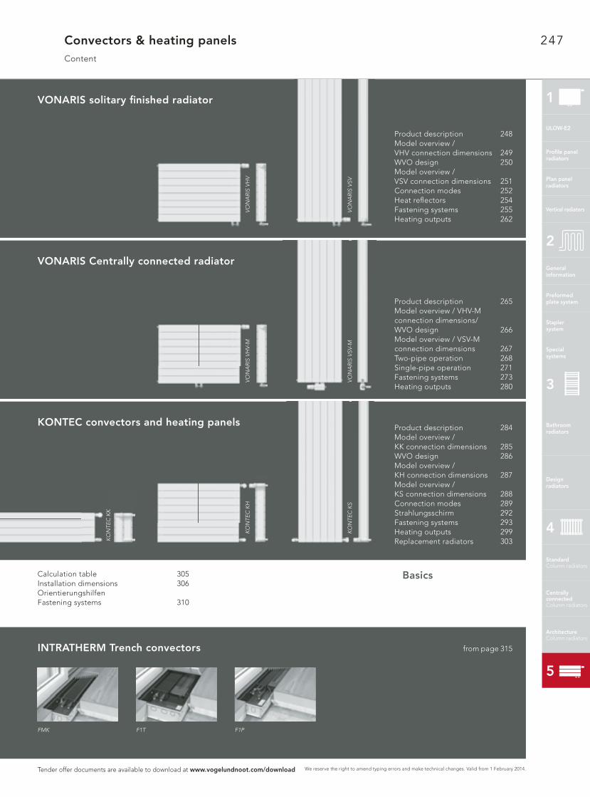
Convectors & heating panelsContent
BasicsCalculation table 305Installation dimensions 306Orientierungshilfen Fastening systems 310
Product description 284Model overview / KK connection dimensions 285WVO design 286Model overview / KH connection dimensions 287Model overview / KS connection dimensions 288Connection modes 289Strahlungsschirm 292Fastening systems 293Heating outputs 299Replacement radiators 303
Product description 265Model overview / VHV-M connection dimensions/ WVO design 266Model overview / VSV-M connection dimensions 267Two-pipe operation 268Single-pipe operation 271Fastening systems 273Heating outputs 280
Product description 248Model overview /VHV connection dimensions 249WVO design 250Model overview / VSV connection dimensions 251Connection modes 252Heat refl ectors 254Fastening systems 255Heating outputs 262
FMK F1T F1P
INTRATHERM Trench convectors from page 315
KONTEC convectors and heating panels
VONARIS Centrally connected radiator
VONARIS solitary fi nished radiator
VO
NA
RIS
VH
VV
ON
AR
IS V
HV-
MK
ON
TEC
KH
KO
NTE
C K
K
VO
NA
RIS
VSV
VO
NA
RIS
VSV
-MK
ON
TEC
KS
Tender offer documents are available to download at www.vogelundnoot.com/download
1
ULOW-E2
Profi le panelradiators
Plan panelradiators
Vertical radiators
Generalinformation
Preformed plate system
Stapler system
Special systems
2
Bathroom radiators
Design radiators
3
Standard Column radiators
Centrallyconnected Column radiators
Architecture Column radiators
4
5
248
We reserve the right to amend typing errors and make technical changes. Valid from 1 February 2014.
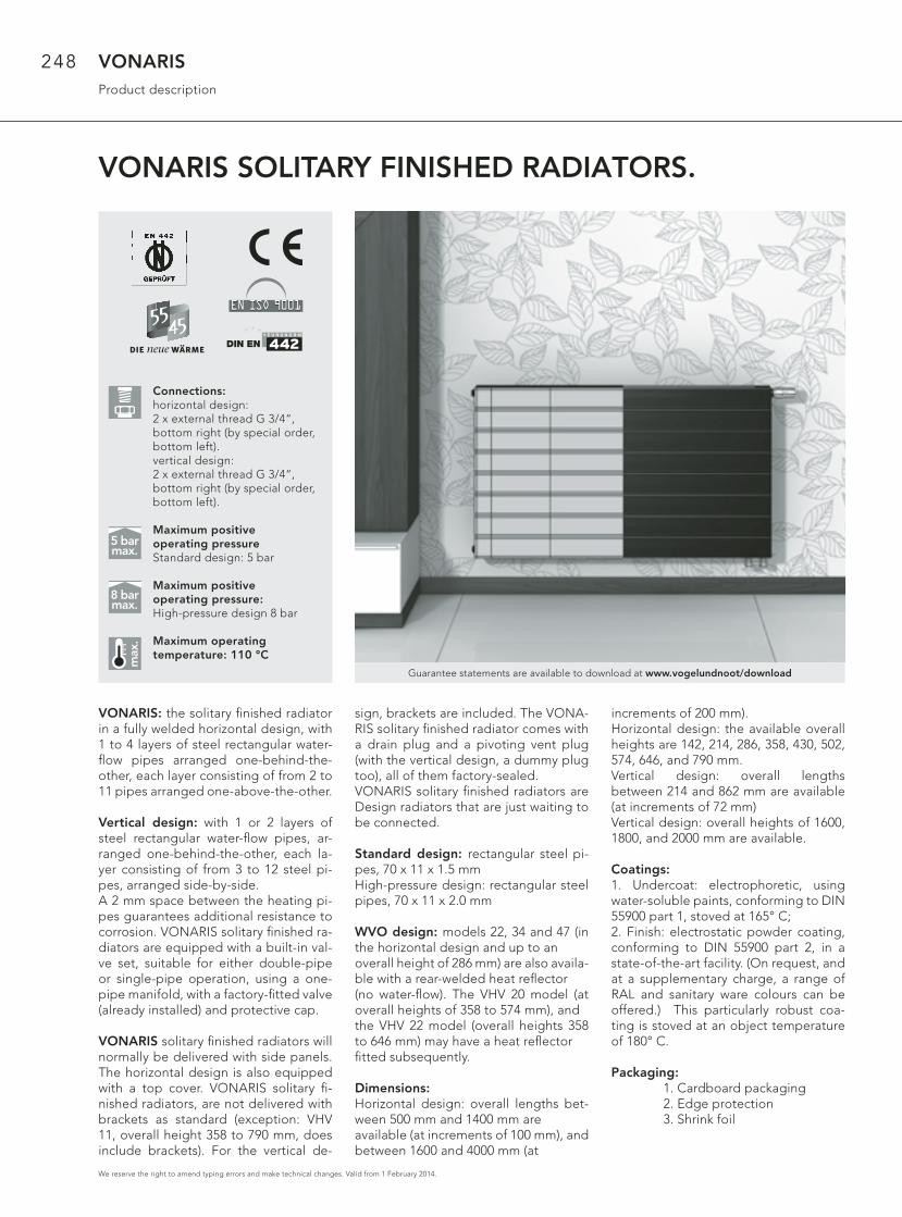
VONARIS SOLITARY FINISHED RADIATORS.
VONARISProduct description
VONARIS: the solitary fi nished radiator in a fully welded horizontal design, with 1 to 4 layers of steel rectangular water-fl ow pipes arranged one-behind-the-other, each layer consisting of from 2 to 11 pipes arranged one-above-the-other.
Vertical design: with 1 or 2 layers of steel rectangular water-fl ow pipes, ar-ranged one-behind-the-other, each la-yer consisting of from 3 to 12 steel pi-pes, arranged side-by-side.A 2 mm space between the heating pi-pes guarantees additional resistance to corrosion. VONARIS solitary fi nished ra-diators are equipped with a built-in val-ve set, suitable for either double-pipe or single-pipe operation, using a one-pipe manifold, with a factory-fi tted valve (already installed) and protective cap.
VONARIS solitary fi nished radiators will normally be delivered with side panels. The horizontal design is also equipped with a top cover. VONARIS solitary fi -nished radiators, are not delivered with brackets as standard (exception: VHV 11, overall height 358 to 790 mm, does include brackets). For the vertical de-
sign, brackets are included. The VONA-RIS solitary fi nished radiator comes with a drain plug and a pivoting vent plug (with the vertical design, a dummy plug too), all of them factory-sealed. VONARIS solitary fi nished radiators are Design radiators that are just waiting to be connected.
Standard design: rectangular steel pi-pes, 70 x 11 x 1.5 mmHigh-pressure design: rectangular steel pipes, 70 x 11 x 2.0 mm
WVO design: models 22, 34 and 47 (in the horizontal design and up to an overall height of 286 mm) are also availa-ble with a rear-welded heat refl ector (no water-fl ow). The VHV 20 model (at overall heights of 358 to 574 mm), and the VHV 22 model (overall heights 358 to 646 mm) may have a heat refl ector fi tted subsequently.
Dimensions:Horizontal design: overall lengths bet-ween 500 mm and 1400 mm are available (at increments of 100 mm), and between 1600 and 4000 mm (at
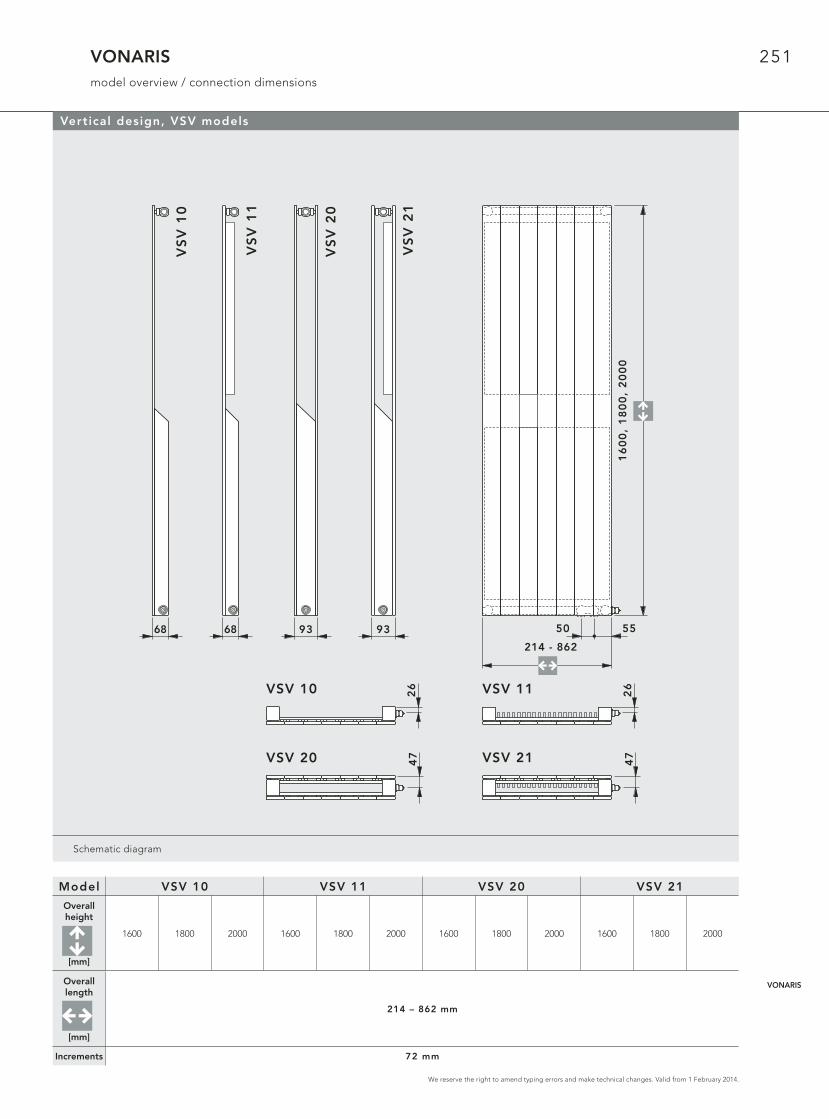
increments of 200 mm).Horizontal design: the available overall heights are 142, 214, 286, 358, 430, 502, 574, 646, and 790 mm.Vertical design: overall lengths between 214 and 862 mm are available (at increments of 72 mm)Vertical design: overall heights of 1600, 1800, and 2000 mm are available.
Coatings:1. Undercoat: electrophoretic, using water-soluble paints, conforming to DIN 55900 part 1, stoved at 165° C; 2. Finish: electrostatic powder coating, conforming to DIN 55900 part 2, in a state-of-the-art facility. (On request, and at a supplementary charge, a range of RAL and sanitary ware colours can be offered.) This particularly robust coa-ting is stoved at an object temperature of 180° C.
Packaging: 1. Cardboard packaging 2. Edge protection 3. Shrink foil
max
.
5 barmax.
8 barmax.
Guarantee statements are available to download at www.vogelundnoot/download
Connections:horizontal design:2 x external thread G 3/4“, bottom right (by special order, bottom left). vertical design:2 x external thread G 3/4“, bottom right (by special order, bottom left).
Maximum positive operating pressureStandard design: 5 bar
Maximum positive operating pressure: High-pressure design 8 bar
Maximum operating temperature: 110 °C
249
We reserve the right to amend typing errors and make technical changes. Valid from 1 February 2014.
Schematic diagram
257
VH
V 4
6
232
VH
V 3
5
175
VH
V 3
4
150
VH
V 2
3
93
VH
V 2
2
93
VH
V 2
0
68
VH
V 1
1
Bauhöhen
358
502
574
790 500 - 2400
500 - 2400
500 - 2400
500 - 2400
500 - 2400
500 - 2400
500 - 2400
500 - 2400
500 - 2400
286
214
142
430
646
VHV 20 47
26VHV 11
VHV 22 47
10
4
VHV 23
VHV 34 47*
VHV 35
10
4
VHV 46
12
9
2550
5
Baulängen
Bauhöhen
358
502
574
790 500 - 2400
500 - 2400
500 - 2400
500 - 2400
500 - 2400
500 - 2400
500 - 2400
500 - 2400
500 - 2400
286
214
142
430
646
2550
5
Baulängen
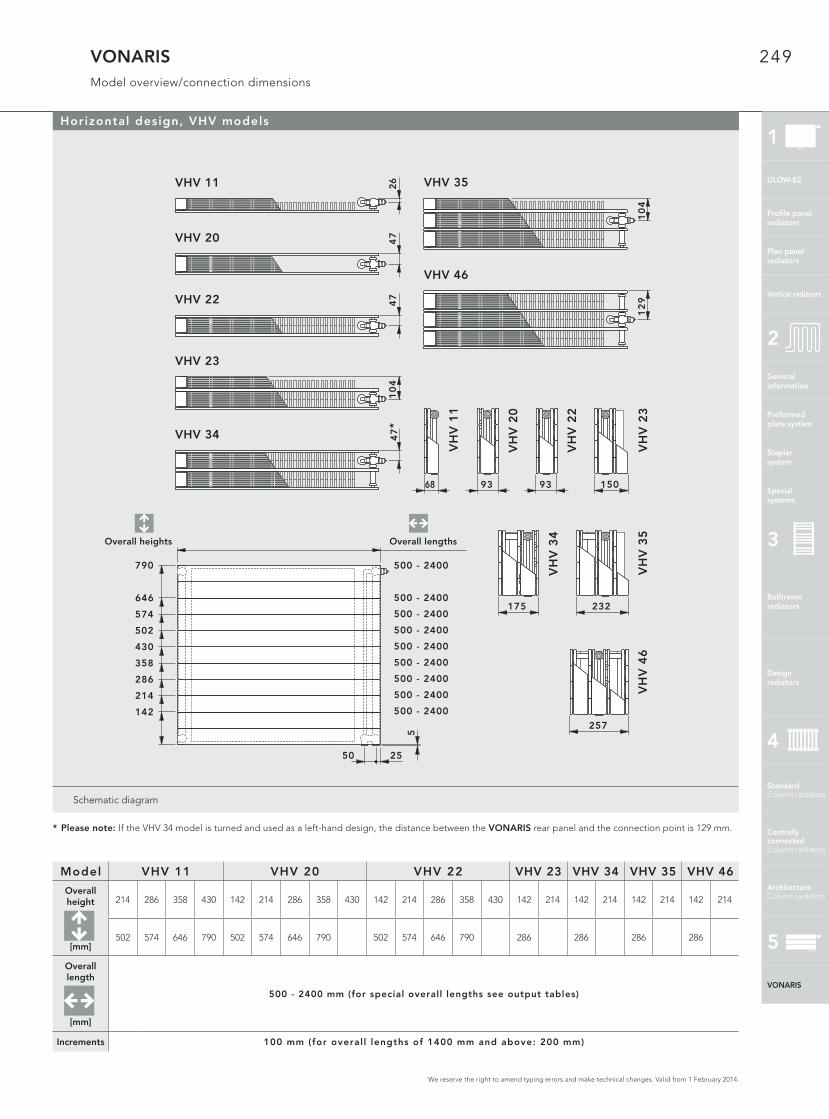
VONARISModel overview/connection dimensions
Horizontal design, VHV models
* Please note: If the VHV 34 model is turned and used as a left-hand design, the distance between the VONARIS rear panel and the connection point is 129 mm.
Model VHV 11 VHV 20 VHV 22 VHV 23 VHV 34 VHV 35 VHV 46
Overall height
[mm]
214 286 358 430 142 214 286 358 430 142 214 286 358 430 142 214 142 214 142 214 142 214
502 574 646 790 502 574 646 790 502 574 646 790 286 286 286 286
Overall length
[mm]
500 - 2400 mm (for special overall lengths see output tables)
Increments 100 mm (for overal l lengths of 1400 mm and above: 200 mm)
Overall lengthsOverall heights
1
VONARIS
ULOW-E2
Profi le panelradiators
Plan panelradiators
Vertical radiators
Generalinformation
Preformed plate system
Stapler system
Special systems
2
Bathroom radiators
Design radiators
3
Standard Column radiators
Centrallyconnected Column radiators
Architecture Column radiators
4
5
250
We reserve the right to amend typing errors and make technical changes. Valid from 1 February 2014.
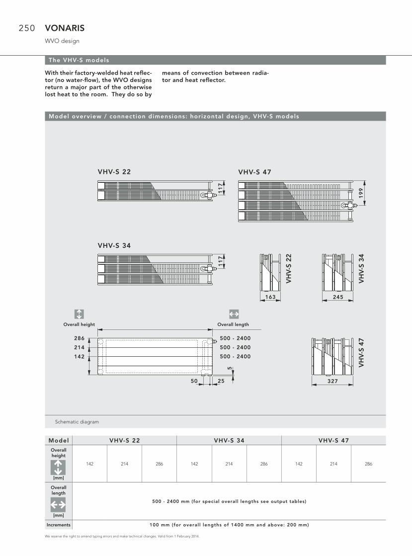
VONARISWVO design
Schematic diagram
The VHV-S models
VH
V-S
22
163
VH
V-S
34
245
VH
V-S
47
327
286
214
142
Bauhöhen
500 - 2400
500 - 2400
500 - 2400
VHV-S 34
11
7
VHV-S 22
11
7
VHV-S 47
19
9
2550
5
Baulängen
Model overview / connection dimensions: horizontal design, VHV-S models
With their factory-welded heat refl ec-tor (no water-fl ow), the WVO designs return a major part of the otherwise lost heat to the room. They do so by
means of convection between radia-tor and heat refl ector.
Model VHV-S 22 VHV-S 34 VHV-S 47
Overall height
[mm]
142 214 286 142 214 286 142 214 286
Overall length
[mm]
500 - 2400 mm (for special overall lengths see output tables)
Increments 100 mm (for overal l lengths of 1400 mm and above: 200 mm)
Overall lengthOverall height
251
We reserve the right to amend typing errors and make technical changes. Valid from 1 February 2014.
VONARISmodel overview / connection dimensions
Schematic diagram
68
VS
V 1
1
93
VS
V 2
0
93
VS
V 2
1
VS
V 1
0
681
60
0,
18
00
, 2
00
0
214 - 862
VSV 20 47
5550
VSV 10 26 VSV 11 26
VSV 21 47
Vertical design, VSV models
Model VSV 10 VSV 11 VSV 20 VSV 21
Overall height
[mm]
1600 1800 2000 1600 1800 2000 1600 1800 2000 1600 1800 2000
Overall length
[mm]
214 – 862 mm
Increments 72 mm
VONARIS
252
We reserve the right to amend typing errors and make technical changes. Valid from 1 February 2014.
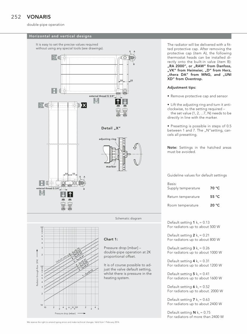
VONARISdouble-pipe operation
Horizontal and vertical designs
It is easy to set the precise values required without using any special tools (see drawings).
N1
23
45
67
Einstellring
Markierung
Detail „X“
The radiator will be delivered with a fi t-ted protective cap. After removing the protective cap (item A), the following thermostat heads can be installed di-rectly onto the built-in valve (item B): „RA 2000“, or „RAW“ from Danfoss, „VK“ from Heimeier, „D“ from Herz, „thera DA“ from MNG, and „UNI XD“ from Oventrop.
Adjustment tips:
• Remove protective cap and sensor
• Lift the adjusting ring and turn it anti-clockwise, to the setting required – the set value (1, 2, ...7, N) needs to be directly in line with the marker.
• Presetting is possible in steps of 0.5 between 1 and 7. The „N“setting, can-cels all presetting.
Note: Settings in the hatched areas must be avoided.
54
32
9102
78
56
34210
Druckverlust [mbar]
He
izkö
rpe
rdu
rch
flu
ss [
l/h
]
103
9876
5
4
3
2
9876
5
4
3
2
10
102
Voreinstellu
ng N - k
v=0,75
7 - kv=
0,63
6 - kv=
0,52
5 - kv=
0,41
4 - kv=
0,31
3 - kv=
0,26
2 - kv=
0,21
1 - kv=
0,13
Guideline values for default settings
Basis:Supply temperature 70 °C
Return temperature 55 °C
Room temperature 20 °C
Default setting 1 kv = 0.13For radiators up to about 500 W
Default setting 2 kv = 0.21For radiators up to about 800 W
Default setting 3 kv = 0.26For radiators up to about 1000 W
Default setting 4 kv = 0.31For radiators up to about 1200 W
Default setting 5 kv = 0.41For radiators up to about 1600 W
Default setting 6 kv = 0.52For radiators up to about. 2000 W
Default setting 7 kv = 0.63For radiators up to about 2400 W
Default setting N kv = 0.75For radiators of more than 2400 W
Chart 1:
Pressure drop [mbar] – double-pipe operation at 2K proportional offset.
It is of course possible to ad-just the valve default setting, whilst there is pressure in the heating system.
50 25
G 3/4" A. G.
X
B
A
N
G 3/4" A. G.
X
B
A
N
50 55
Schematic diagram
external thread G 3/4“
external thread G 3/4“
Rad
iato
r th
roug
h-fl o
w
Pressure drop
Default settin
g
adjusting ring
marker
253
We reserve the right to amend typing errors and make technical changes. Valid from 1 February 2014.
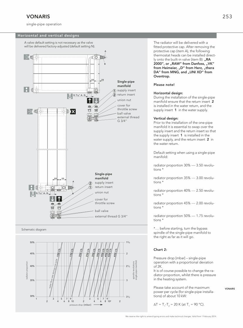
VONARISsingle-pipe operation
Schematic diagram
Horizontal and vertical designs
A valve default setting is not necessary as the valve will be delivered factory-adjusted (default setting N).
21
The radiator will be delivered with a fi tted protective cap. After removing the protective cap (item A), the following thermostat heads can be installed direct-ly onto the built-in valve (item B): „RA 2000“, or „RAW“ from Danfoss, „VK“ from Heimeier, „D“ from Herz, „thera DA“ from MNG, and „UNI XD“ from Oventrop.
Please note!
Horizontal design:During the installation of the single-pipe manifold ensure that the return insert 2 is installed in the water return, and the supply insert 1 in the water supply.
Vertical design:Prior to the installation of the one-pipe manifold it is essential to swap over the supply insert and the return insert so that the supply insert 1 is installed in the water supply, and the return insert 2 in the water return.
2
Druckverlust [mbar]
1 34
56 8 10
7 92
3 5 7 94 6 8 102 2
31/2
3
21/2
2
13/4
Sp
ind
elv
erd
reh
un
ge
nV
N E
inro
hrv
ert
eil
er
He
izkö
rpe
ran
teil
30%
35%
40%
45%
50%
Kre
isw
asse
rdu
rch
flu
ss 1
00
l/h
15
0 l
/h
25
0 l
/h
20
0 l
/h
30
0 l
/h3
50
l/h
40
0 l
/h4
50
l/h
50
0 l
/h
60
0 l
/h
Default setting when using a single-pipe manifold:
radiator proportion 30% --- 3.50 revolu-tions *
radiator proportion 35% --- 3.00 revolu-tions *
radiator proportion 40% --- 2.50 revolu-tions *
radiator proportion 45% --- 2.00 revolu-tions *
radiator proportion 50% --- 1.75 revolu-tions *
*… before starting, turn the bypass spindle of the single-pipe manifold to the right as far as it will go.
Chart 2:
Pressure drop [mbar] – single-pipe operation with a proportional deviation of 2K.It is of course possible to change the ra-diator proportion, whilst there is pressure in the heating system.
Please take account of the maximum power per cycle (for single-pipe installa-tions) of about 10 kW: ΔT = T1-T2 = 20 K (at T1 = 90 °C).
50 25
G 3/4" A. G.
B
A
N
12
G 3/4" A. G. B
A
N
50 55
rad
iato
r p
rop
ort
ion
pressure drop
spin
dle
revo
lutio
nssi
ngle
-pip
e m
anifo
ld
wat
er fl
ow ra
te d
urin
g o
ne c
ycle
Single-pipe manifoldsupply insertreturn insert
union nut
cover for throttle screwball valveexternal threadG 3/4‘’
Single-pipe manifoldsupply insertreturn insert
union nut
cover for throttle screw
ball valve
external thread G 3/4‘’
VONARIS
254
We reserve the right to amend typing errors and make technical changes. Valid from 1 February 2014.
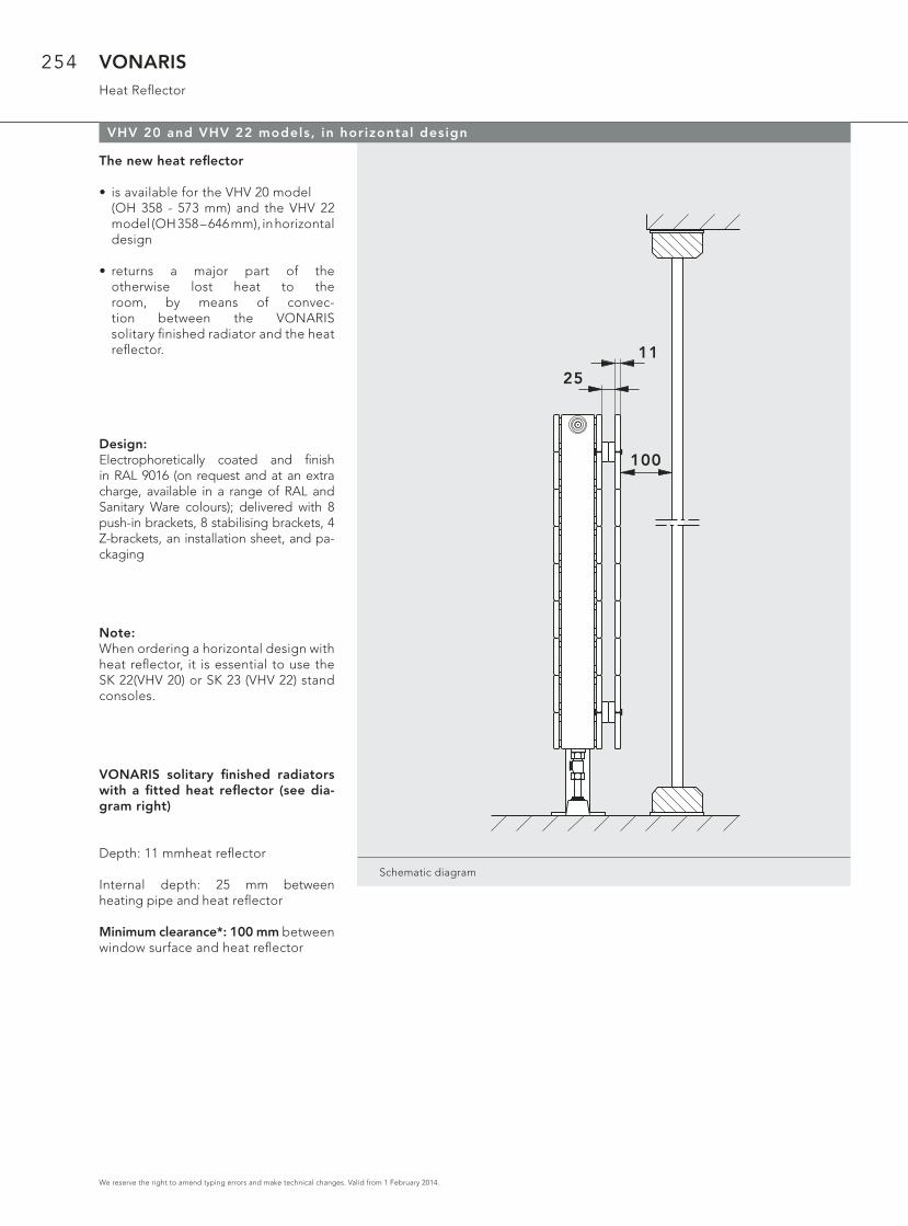
VONARISHeat Refl ector
Schematic diagram
VHV 20 and VHV 22 models, in horizontal design
100
11
25
The new heat refl ector
• is available for the VHV 20 model (OH 358 - 573 mm) and the VHV 22 model (OH 358 – 646 mm), in horizontal design
• returns a major part of the otherwise lost heat to the room, by means of convec- tion between the VONARIS solitary fi nished radiator and the heat refl ector.
Design:Electrophoretically coated and fi nish in RAL 9016 (on request and at an extra charge, available in a range of RAL and Sanitary Ware colours); delivered with 8 push-in brackets, 8 stabilising brackets, 4 Z-brackets, an installation sheet, and pa-ckaging
Note:When ordering a horizontal design with heat refl ector, it is essential to use the SK 22(VHV 20) or SK 23 (VHV 22) stand consoles.
VONARIS solitary fi nished radiators with a fi tted heat refl ector (see dia-gram right)
Depth: 11 mm heat refl ector
Internal depth: 25 mm between heating pipe and heat refl ector
Minimum clearance*: 100 mm between window surface and heat refl ector

255
We reserve the right to amend typing errors and make technical changes. Valid from 1 February 2014.
VONARIS Wall mounting WA 11welded bracket positions
Wall mounting WA 11 for models VHV 11 and VHV 23
Model Wall mounting WA 11 for VHV 11 or VHV 23
Overallheight
from214 mm
to286 mm
VHV 11 for Wall mounting WA 11
Overallheight
from214 mm
to286 mm
VHV 11 for Wall mounting WA 11
Overallheight
from214 mm
to286 mm
Schematic diagram
Attention! With the horizontal design only the models VHV-M 10/11 (OH 358 - 790 mm) are by default supplied with brackets. If the models VHV-M 20 (OH 358 - 790 mm), VHV-M 22 (OH 214 - 790) and VHV-M 34 (142 – 286 mm) are wall-mounted using wall mounting WA 11, you are required to order these models as a special version, equipped with brackets.
500 - 2000
160 160
85
12
0
160 1601/2 1/2
2200 - 4000
85
12
0
13
02
20
500 - 2000
160 160
13
02
20
160 160
2200 - 4000
1/2 1/2
13
04
20
500 - 2000
160 160
40
13
04
20
160 160
2200 - 400040
1/2 1/2
60
14
60
14
Note: special order
VHV 23 VHV 11
VONARIS
256
We reserve the right to amend typing errors and make technical changes. Valid from 1 February 2014.
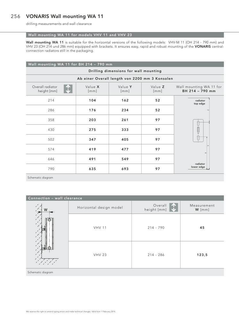
VONARIS Wall mounting WA 11drilling measurements and wall clearance
Wall mounting WA 11 for models VHV 11 and VHV 23
Wall mounting WA 11 is suitable for the horizontal versions of the following models: VHV-M 11 (OH 214 - 790 mm) and VHV 23 (OH 214 und 286 mm) equipped with brackets. It ensures easy, rapid and robust mounting of the VONARIS central-connection radiators still in the packaging.
Wall mounting WA 11 for BH 214 – 790 mm
Connection – wall c learance
Horizontal design modelOveral l
height [mm]Measurement
W [mm]
VHV 11 214 - 790 45
VHV 23 214 - 286 123,5
Schematic diagram
Dril l ing dimensions for wall mounting
Ab einer Overal l length von 2200 mm 3 Konsolen
Overall radiatorheight [mm]
Value X [mm]
Value Y [mm]
Value Z [mm]
Wall mounting WA 11 for BH 214 – 790 mm
214 104 162 52
286 176 234 52
358 203 261 97
430 275 333 97
502 347 405 97
574 419 477 97
646 491 549 97
790 635 693 97
Schematic diagram
HeizkörperOberkante
HeizkörperUnterkante
XY
ZW
radiator top edge
radiator lower edge

257
We reserve the right to amend typing errors and make technical changes. Valid from 1 February 2014.
VONARIS VONOFIXpositions of the insertion (push-in) brackets
VONOFIX rapid-instal lation console for the VHV models
VHV 20 and 22 models: OH 214 – 790 mm, VHV 34 model: OH 214 and 286 mm
OH 214: for the VONOFIX 1 OH 574 and 646: for the VONOFIX 4
OH 286 and 358: for the VONOFIX 2
OH 430 and 502: for the VONOFIX 3 OH 790: for the VONOFIX 5
Schematic diagram
215
BH
286
215
7070 *
BH
358
143
7070 *
BH
214
503
BH
574
503
7070 *
BH
646
359
BH
430
BL 2200 - 4000
1/2 Baulänge
359
7070 *
BH
502
1/2 Baulänge
647
7070 *
BL 500 - 2000
40
BH
790
Important: the installation of VHV models with insertion (push-in) brackets is only feasible when using the VONOFIX rapid-installation console!
*If you are using a right-angled valve block to connect your VHV models, please leave clearance of 110 mm, instead of 70 mm, from the radiator’s outside edge for the installation of VONOFIX.
Note: for an overall length of 2200 mm and greater an additional piece of foot console must be used!
VONARIS
258
We reserve the right to amend typing errors and make technical changes. Valid from 1 February 2014.
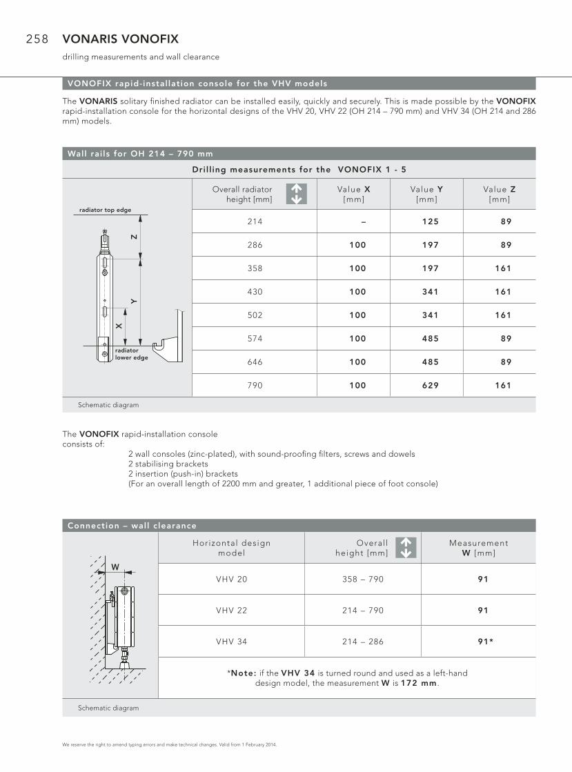
VONARIS VONOFIXdrilling measurements and wall clearance
VONOFIX rapid-instal lation console for the VHV models
The VONARIS solitary fi nished radiator can be installed easily, quickly and securely. This is made possible by the VONOFIX rapid-installation console for the horizontal designs of the VHV 20, VHV 22 (OH 214 – 790 mm) and VHV 34 (OH 214 and 286 mm) models.
Wall rai ls for OH 214 – 790 mm
Dri l l ing measurements for the VONOFIX 1 - 5
Overall radiatorheight [mm]
Value X [mm]
Value Y [mm]
Value Z [mm]
214 – 125 89
286 100 197 89
358 100 197 161
430 100 341 161
502 100 341 161
574 100 485 89
646 100 485 89
790 100 629 161
Schematic diagram
X
Heizkörper Oberkante
HeizkörperUnterkante
YZ
Connection – wall c learance
Horizontal design model
Overal l height [mm]
MeasurementW [mm]
VHV 20 358 – 790 91
VHV 22 214 – 790 91
VHV 34 214 – 286 91*
*Note: if the VHV 34 is turned round and used as a left-hand design model, the measurement W is 172 mm .
W
Schematic diagram
The VONOFIX rapid-installation console consists of: 2 wall consoles (zinc-plated), with sound-proofi ng fi lters, screws and dowels 2 stabilising brackets 2 insertion (push-in) brackets (For an overall length of 2200 mm and greater, 1 additional piece of foot console)
radiator top edge
radiator lower edge

259
We reserve the right to amend typing errors and make technical changes. Valid from 1 February 2014.
VONARISwelded brackets positions
VSV modelsOverall length
[mm]
214 286 358 430 - 862
Schematic diagram
214
16
00
, 1
80
0,
20
00
13
09
0
40
286
16
00
, 1
80
0,
20
00
13
0
7171
90
40
358
16
00
, 1
80
0,
20
00
13
09
0
7171
40
BL 430 - 862
16
00
, 1
80
0,
20
00
13
0
107107
90
40
60
48
60
14
60
14
60
14
VSV 10 VSV 11 VSV 20 VSV 21
Wall c learance measurements: WA 10 and WA 11 wall mounting brackets for the VSV models
Connection – wall c learance
Wall mounting brackets model
Vert ical design model
Measurement W [mm]
WA 10 VSV 10/11* 35
WA 10 VSV 20/21 79,5
WA 11 VSV 10/11* 45
WA 11 VSV 20/21 89,5
*Note : i f you are instal l ing the VSV 10 or VSV 11 models with a r ight-angled-design connect ion, please use the appropriate dr i l l ing consoles or angle-f ishplate moun-
t ing brackets, to achieve the required wal l c learance.
Schematic diagram
W
VONARIS

260
We reserve the right to amend typing errors and make technical changes. Valid from 1 February 2014.
VONARIS installation consoles
Wall consoles WK 10 – 12: posit ioning for VHV models (up to an overal l height of 286 mm)
Note: when using more than 2 wal l consoles the addit ional wal l consoles must be placed at regular intervals a long the l ine X.
WK 10 wall console
VHV 11 VHV 20 VHV 22
WK 11 wall console WK 12 wall console
VHV 23 VHV 34 VHV 35 VHV 46
Schematic diagram
68
501
15
2511
5
93
2511
5
93
50
15
0
19
7
25
17
5
19
7
50
23
2
27
9 25
25
7
27
9
Stand consoles SK 22 and SK 23: positioning for VHV models (for an overall height of 358 mm and greater)
Note : for an overal l length of 2200 mm and greater, a 3rd stand console must be used!
Schematic diagram
165 165constant
1/2 overall length 1/2 overall length
constant
150 150X
constantconstant

261
We reserve the right to amend typing errors and make technical changes. Valid from 1 February 2014.
VONARIS installation consoles
Stand consoles SK 10 – 19: positioning for the VHV/VHV-S models (up to an overall height of 286 mm)
Note: for an overal l length of 2200 mm and greater, a 3rd stand console must be used!
SK 10 / SK 11
VHV 11
SK 12 / SK 13
VHV 20
SK 12 / SK 13 SK 14 / SK 15
VHV 22 VHV 23 VHV-S 22 VHV 34
SK 14 / SK 15 SK 16 / SK 17 SK 18 / SK 19
VHV 35 VHV-S 34 VHV 46 VHV-S 47
Schematic diagram
X
88
,5
93
46
88
,5
X
10
3
15
0
16
6,5
X1
637
7
16
6,5
X1
758
9
16
6,5
X2
3214
6
16
6,5
X2
4515
9
24
5
X2
571
32
32
7
X3
27
16
1
X
88
,5
93
46
X
65
68
33
Window sill support FBT 20: positioning for the VHV/VHV-S models (up to an overall height of 286 mm)
Window si l l support for subsequent instal lat ion with the VHV/VHV-S 22–47 models of the VONA-RIS sol i tary f in ished radiator (up to an overal l height of 286 mm )
Note: for an overal l length of 2200 mm and greater, a 3rd stand console must be used!
Schematic diagram
150 150constant
1/2 overall length 1/2 overall length
constant
150 150
con-stant
1/2 overall length 1/2 overall length
con-stant
VONARIS
262
We reserve the right to amend typing errors and make technical changes. Valid from 1 February 2014.
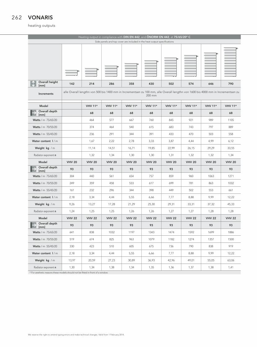
VONARISheating outputs
Heating output in compliance with DIN EN 442, and ÖNORM EN 442, at 75/65/20° C
Side panels and top cover are included in the heat output specifi cations
Overall height[mm]
142 214 286 358 430 502 574 646 790
Increments alle Overall lengthn von 500 bis 1400 mm in Incrementsen zu 100 mm, alle Overall lengthn von 1600 bis 4000 mm in Incrementsen zu
200 mm
Model VHV 11* VHV 11* VHV 11* VHV 11* VHV 11* VHV 11* VHV 11* VHV 11*
Overall depth [mm]
68 68 68 68 68 68 68 68
Watts / m 75/65/20 464 577 667 760 845 921 989 1105
Watts / m 70/55/20 374 464 540 615 683 743 797 889
Watts / m 55/45/20 236 291 344 391 433 470 503 558
Water content l / m 1,67 2,22 2,78 3,33 3,87 4,44 4,99 6,12
Weight kg / m 11,14 14,51 16,71 19,85 22,99 26,15 29,29 33,55
Radiator exponent n 1,32 1,34 1,30 1,30 1,31 1,32 1,32 1,34
Model VHV 20 VHV 20 VHV 20 VHV 20 VHV 20 VHV 20 VHV 20 VHV 20 VHV 20
Overall depth [mm]
93 93 93 93 93 93 93 93 93
Watts / m 75/65/20 304 440 561 654 757 859 960 1063 1271
Watts / m 70/55/20 249 359 458 533 617 699 781 863 1032
Watts / m 55/45/20 161 232 296 344 398 449 502 553 661
Water content l / m 2,18 3,34 4,44 5,55 6,66 7,77 8,88 9,99 12,22
Weight kg / m 9,26 13,27 17,28 21,29 25,30 29,31 33,31 37,32 45,33
Radiator exponent n 1,24 1,25 1,25 1,26 1,26 1,27 1,27 1,28 1,28
Model VHV 22 VHV 22 VHV 22 VHV 22 VHV 22 VHV 22 VHV 22 VHV 22 VHV 22
Overall depth [mm]
93 93 93 93 93 93 93 93 93
Watts / m 75/65/20 641 838 1032 1197 1343 1474 1592 1699 1886
Watts / m 70/55/20 519 674 825 963 1079 1182 1274 1357 1500
Watts / m 55/45/20 330 423 510 605 675 736 790 838 919
Water content l / m 2,18 3,34 4,44 5,55 6,66 7,77 8,88 9,99 12,22
Weight kg / m 13,97 20,59 27,23 30,89 36,93 42,96 49,01 55,05 63,06
Radiator exponent n 1,30 1,34 1,38 1,34 1,35 1,36 1,37 1,38 1,41
* For aesthetic reasons these models should not be fi tted in front of a window.
263
We reserve the right to amend typing errors and make technical changes. Valid from 1 February 2014.
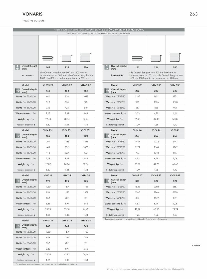
VONARISheating outputs
Overall height [mm]
142 214 286
Increments alle Overall lengthn von 500 bis 1400 mm in Incrementsen zu 100 mm, alle Overall lengthn von 1600 bis 4000 mm in Incrementsen zu 200 mm
Model VHV-S 22 VHV-S 22 VHV-S 22
Overall depth [mm]
163 163 163
Watts / m 75/65/20 641 838 1032
Watts / m 70/55/20 519 674 825
Watts / m 55/45/20 330 423 510
Water content l / m 2,18 3,34 4,44
Weight kg / m 19,43 28,34 37,24
Radiator exponent n 1,30 1,34 1,38
Model VHV 23* VHV 23* VHV 23*
Overall depth [mm]
150 150 150
Watts / m 75/65/20 797 1035 1261
Watts / m 70/55/20 645 832 1008
Watts / m 55/45/20 410 522 623
Water content l / m 2,18 3,34 4,44
Weight kg / m 17,02 24,84 32,66
Radiator exponent n 1,30 1,34 1,38
Model VHV 34 VHV 34 VHV 34
Overall depth [mm]
175 175 175
Watts / m 75/65/20 1050 1394 1723
Watts / m 70/55/20 856 1123 1377
Watts / m 55/45/20 552 707 851
Water content l / m 3,33 4,99 6,66
Weight kg / m 23,93 35,18 46,42
Radiator exponent n 1,26 1,33 1,38
Model VHV-S 34 VHV-S 34 VHV-S 34
Overall depth [mm]
245 245 245
Watts / m 75/65/20 1050 1394 1723
Watts / m 70/55/20 856 1123 1377
Watts / m 55/45/20 552 707 851
Water content l / m 3,33 4,99 6,66
Weight kg / m 29,39 42,92 56,44
Radiator exponent n 1,26 1,33 1,38
* For aesthetic reasons these models should not be fi tted in front of a window.
Overall height [mm]
142 214 286
Increments alle Overall lengthn von 500 bis 1400 mm in Incrementsen zu 100 mm, alle Overall lengthn von 1600 bis 4000 mm in Incrementsen zu 200 mm
Model VHV 35* VHV 35* VHV 35*
Overall depth [mm]
232 232 232
Watts / m 75/65/20 1197 1651 1971
Watts / m 70/55/20 971 1326 1570
Watts / m 55/45/20 619 828 964
Water content l / m 3,33 4,99 6,66
Weight kg / m 26,98 39,42 51,86
Radiator exponent n 1,29 1,35 1,40
Model VHV 46 VHV 46 VHV 46
Overall depth [mm]
257 257 257
Watts / m 75/65/20 1454 2072 2447
Watts / m 70/55/20 1179 1664 1949
Watts / m 55/45/20 752 1040 1197
Water content l / m 4,53 6,79 9,06
Weight kg / m 33,89 49,76 65,62
Radiator exponent n 1,29 1,35 1,40
Model VHV-S 47 VHV-S 47 VHV-S 47
Overall depth [mm]
327 327 327
Watts / m 75/65/20 1522 2302 2667
Watts / m 70/55/20 1240 1846 2128
Watts / m 55/45/20 800 1149 1311
Water content l / m 4,53 6,79 9,06
Weight kg / m 41,27 60,50 79,74
Radiator exponent n 1,26 1,36 1,39
* For aesthetic reasons these models should not be fi tted in front of a window.
Heating output in compliance with DIN EN 442, and ÖNORM EN 442, at 75/65/20° C
Side panels and top cover are included in the heat output specifi cations
VONARIS
264
We reserve the right to amend typing errors and make technical changes. Valid from 1 February 2014.
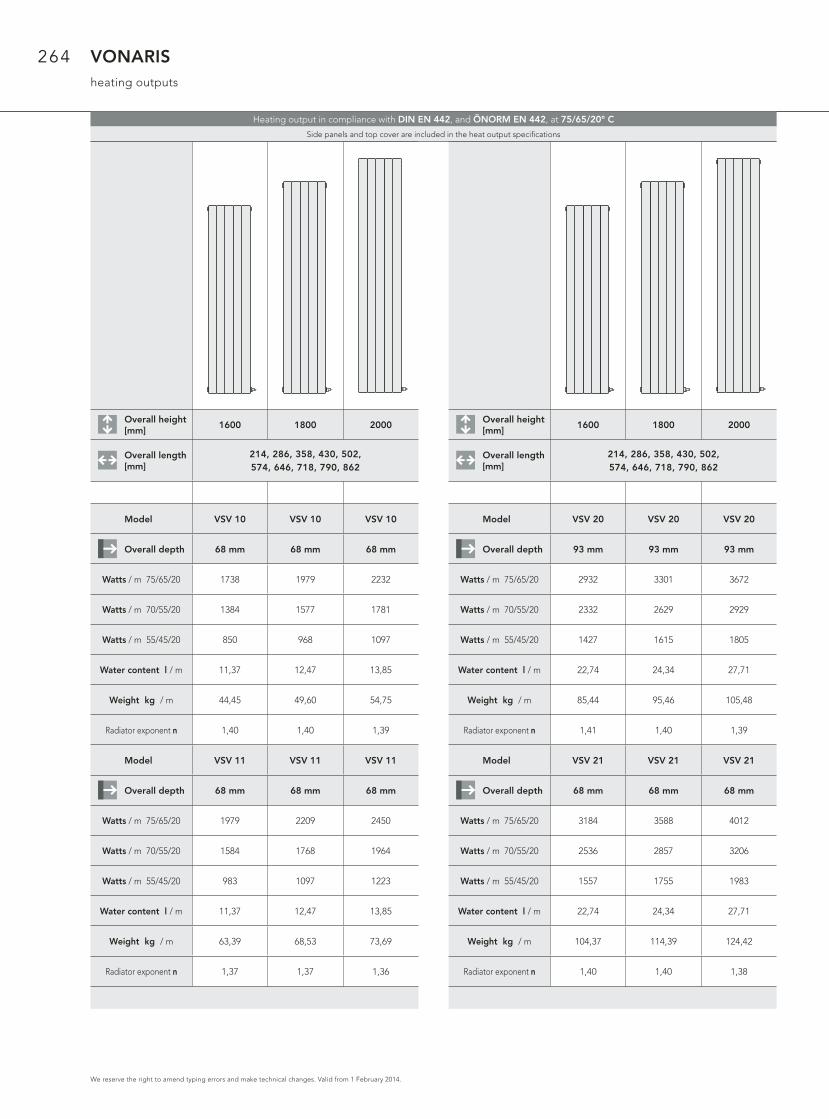
VONARISheating outputs
Overall height [mm]
1600 1800 2000
Overall length [mm]
214, 286, 358, 430, 502, 574, 646, 718, 790, 862
Model VSV 10 VSV 10 VSV 10
Overall depth 68 mm 68 mm 68 mm
Watts / m 75/65/20 1738 1979 2232
Watts / m 70/55/20 1384 1577 1781
Watts / m 55/45/20 850 968 1097
Water content l / m 11,37 12,47 13,85
Weight kg / m 44,45 49,60 54,75
Radiator exponent n 1,40 1,40 1,39
Model VSV 11 VSV 11 VSV 11
Overall depth 68 mm 68 mm 68 mm
Watts / m 75/65/20 1979 2209 2450
Watts / m 70/55/20 1584 1768 1964
Watts / m 55/45/20 983 1097 1223
Water content l / m 11,37 12,47 13,85
Weight kg / m 63,39 68,53 73,69
Radiator exponent n 1,37 1,37 1,36
Overall height [mm]
1600 1800 2000
Overall length [mm]
214, 286, 358, 430, 502, 574, 646, 718, 790, 862
Model VSV 20 VSV 20 VSV 20
Overall depth 93 mm 93 mm 93 mm
Watts / m 75/65/20 2932 3301 3672
Watts / m 70/55/20 2332 2629 2929
Watts / m 55/45/20 1427 1615 1805
Water content l / m 22,74 24,34 27,71
Weight kg / m 85,44 95,46 105,48
Radiator exponent n 1,41 1,40 1,39
Model VSV 21 VSV 21 VSV 21
Overall depth 68 mm 68 mm 68 mm
Watts / m 75/65/20 3184 3588 4012
Watts / m 70/55/20 2536 2857 3206
Watts / m 55/45/20 1557 1755 1983
Water content l / m 22,74 24,34 27,71
Weight kg / m 104,37 114,39 124,42
Radiator exponent n 1,40 1,40 1,38
Heating output in compliance with DIN EN 442, and ÖNORM EN 442, at 75/65/20° C
Side panels and top cover are included in the heat output specifi cations

265
We reserve the right to amend typing errors and make technical changes. Valid from 1 February 2014.
VONARIS-MProduct description
VONARIS-M CENTRAL-CONNECTION RADIATOR
VONARIS: the central-connection radi-ator in a fully welded horizontal design, with from 1 to 4 layers of steel rectan-gular water-fl ow pipes, arranged one-behind-the-other, each layer consisting of from 2 to 11 pipes arranged one-above-the-other. Vertical design with 1 or 2 layers of steel rectangular water-fl ow pipes, arranged one-behind-the-other, each layer consisting of from 3 to 12 steel pipes, arranged side-by-side.
A 2 mm space between the heating pi-pes guarantees additional resistance to corrosion. VONARIS central-connection radiators are equipped with a built-in valve set, suitable for either double-pipe or single-pipe operation, using a one-pipe manifold, with a factory-fi tted valve (already installed) and protective cap.
Vertical central-connection radiators are delivered with a connection set, including a factory-fi tted valve, a pro-tective cap and a cover. Depending on the customer‘s preferences they will also be ready for double-pipe or
single-pipe operation and for angled or through-fl ow connection. VONARIS central-connection radiators are usual-ly delivered with side panels. The ho-rizontal design also comes equipped with a top cover. With the VONARIS central-connection radiators, brackets are not included as a matter of course (exception: VHV-M 11, where brackets are included). The VONARIS central-connection ra-diator comes with a drain plug and a pivoting vent plug (with the vertical design, also two dummy plugs), all of them factory-sealed. VONARIS cen-tral-connection radiators are Design radiators that are ready to connect. Standard design: rectangular steel pipes, 70 x 11 x 1.5 mmHigh-pressure design: rectangular steel pipes, 70 x 11 x 2.0 mm
Dimensions:Horizontal design: overall lengths between 500 mm and 1400 mm are available (at increments of 100 mm), and between 1600 mm and 2400 mm
(at increments of 200 mm)Horizontal design: the available overall heights are 142, 214, 286, 358, 430, 502, 574, 646 and 790 mmVertical design: overall lengths between 214 mm and 862 mm are available (at increments of 72 mm)Vertical design: overall heights of 1600, 1800 and 2000 mm are available.
Coatings:1. Undercoat: electrophoretic, using water-soluble paints, conforming to DIN 55900 part 1, stoved at 165° C; 2. Finish: electrostatic powder coa-ting, conforming to DIN 55900 part 2, in a state-of-the-art facility. (On re-quest, and at a supplementary charge, a range of RAL and sanitary ware co-lours can be offered.) This particularly robust coating is stoved at an object temperature of 180° C.
Packaging: 1. Cardboard packaging 2. Edge protection 3. Shrink foil
max
.
5 barmax.
8 barmax.
Guarantee statements are available to download at www.vogelundnoot/download
Connections:Horizontal design: 2 x external thread G 3/4“, bottom centre
Vertical design: 2 x external thread G 3/4“, bottom centre
Maximum positive operating pressureStandard design: 5 bar
Maximum positive operating pressure: High-pressure design: 8 bar
Maximum operating temperature: 110° C
1
VONARIS
VONARIS-M
ULOW-E2
Profi le panelradiators
Plan panelradiators
Vertical radiators
Generalinformation
Preformed plate system
Stapler system
Special systems
2
Bathroom radiators
Design radiators
3
Standard Column radiators
Centrallyconnected Column radiators
Architecture Column radiators
4
5

266
We reserve the right to amend typing errors and make technical changes. Valid from 1 February 2014.
VONARIS-Mmodel overview / connection dimensions
Horizontal design, VHV-M models
* Note: if the VHV-M 34 model is turned around so that the valve is located to the left, the distance between the VONARIS rear panel and the connection point is 129 mm.
Model VHV-M 10 VHV-M 11 VHV-M 20 VHV-M 22 VHV-M S 22 VHV-M 34 VHV-M 46 VHV-M S 46Overall height
[mm]
358 430 502 358 430 502 358 430 502 214 286 358 214 286 142 214 142 214 142 214
574 646 718 574 646 718 574 646 718 430 502 574 286 286 286
790 790 790 646 718 790
Overall length
[mm]
500 - 2400 mm
Increments 100 mm (ab Baulänge 1400 mm: 200 mm)
Horizontal design, Horizontal design, VHV-M S models
Schematische Darstellung
257
12
9
VHV-M 46
68
26
VHV-M 11
93
47
VHV-M 20
93
47
VHV-M 22
175
47
*VHV-M 34
68
26
VHV-M 10
Bauhöhen
358
502
574
790 500 - 2400
500 - 2400
500 - 2400
500 - 2400
500 - 2400
500 - 2400
500 - 2400
500 - 2400
500 - 2400
500 - 2400
286
214
142
430
646
718
Baulänge/2
Baulängen
163
11
7
VHV-M S 22
327
VHV-M S 46
19
9
Die WVO-Ausführung mit werkseitig angeschweißtem, nicht wasserführendem Strahlungsschirm führt durch Konvektion zwischen Heizkörper und Strahlungsschirm den überwie-genden Teil der sonst verlorenen Wärme in den Raum zurück.
Schematic diagram

267
We reserve the right to amend typing errors and make technical changes. Valid from 1 February 2014.
VONARIS-M model overview / connection dimensions
Angled design connect ion set Connect ion set in through-f low design
Fastening set Model Measurement Y [mm] Fastening set Model Measurement Z [mm]
* VSV-M 10 * WA 10 VSV-M 10/11 35
WA 10 VSV-M 20/21 53 WA 10 VSV-M 20/21 79,5
* VSV-M 11 * WA 11 VSV-M 10/11 45
WA 11 VSV-M 20/21 63 WA 11 VSV-M 20/21 89,5
Schematic diagram
Model overview / connection dimensions: vertical design, VSV-M models
Model VSV-M 10 VSV-M 11 VSV-M 20 VSV-M 21Overall height
[mm]
600 800 1000 800 1000 1200 600 800 1000 800 1000 1200
1200 1400 1600 1400 1600 1800 1200 1400 1600 1400 1600 1800
1800 2000 2200 2000 2200 1800 2000 2200 2000 2200
2400 2600 2400 2600
Overall length
[mm]
214 - 862 mm
Increments 72 mm
* Note: when installing the VSV-M 10 and VSV-M 11 models with an angled connection set (ZE, EE), please use the appropri-ate drill consoles and angled fi shplates to ensure that the required distance from the wall is maintained.
VSV-M 10
VSV-M 20
VSV-M 11
VSV-M 21
VS
V-M
11
VS
V-M
20
VS
V-M
21
VS
V-M
10
ZCLICK
Covering cap for fitting
47
93
26
68
47
93
26
68
50
50
Overall length/2
Y
ZE / EE
27
ZE / EEZD / ED
Z
ZD / ED
Connection setZE Double-pipe operation
angled designZD Double-pipe operation
through-flow designEE Single-pipe operation
angled designED Single-pipe operation
through-flow design
Y 27
VONARIS-M

268
We reserve the right to amend typing errors and make technical changes. Valid from 1 February 2014.
VONARIS-MDouble-pipe operation
The radiator will be delivered with a fi tted protective cap. After removing the protective cap (item A), the following thermostat heads can be installed directly onto the built-in valve (item B): „RA 2000“, or „RAW“ from Danfoss, „VK“ from Heimeier, „D“ from Herz, „thera DA“ from MNG, and „UNI XD“ from Oventrop.
Adjustment tips:
• Remove protective cap and sensor
• Lift the adjusting ring and turn it anti-clockwise, to the setting required – the set value (1, 2, ...7, N) needs to be directly in line with the marker.
• Presetting is possible in steps of 0.5 between 1 and 7. The „N“setting, cancels all presetting.
Horizontal and vertical designs
Schematic diagram
50
G 3/4" A. G.
X
B
N
Baulänge/2
It is easy to set the precise values required without using any special tools (see drawings).
CLICKArmaturen-Abdeckkappe
N
50
X
B
A
Note:Settings in the hatchedarea must be avoided.
N1
23
45
67
adjusting ring
marker
Detail „X“
Covering cap for fi tting
Overall length/2

269
We reserve the right to amend typing errors and make technical changes. Valid from 1 February 2014.
VONARIS-MDouble-pipe operation
54
32
9102
78
56
34210
Druckverlust [mbar]
He
izkö
rpe
rdu
rch
flu
ss [
l/h
]
103
9876
5
4
3
2
9876
5
4
3
2
10
102
Voreinstellu
ng N - k
v=0,75
7 - kv=
0,63
6 - kv=
0,52
5 - kv=
0,41
4 - kv=
0,31
3 - kv=
0,26
2 - kv=
0,21
1 - kv=
0,13
Horizontal design
Guideline values for default settings
Basis:Supply temperature 70 °C
Return temperature 55 °C
Room temperature 20 °C
Default setting 1 kv = 0.13For radiators up to about 500 W
Default setting 2 kv = 0.21For radiators up to about 800 W
Default setting 3 kv = 0.26For radiators up to about 1000 W
Default setting 4 kv = 0.31For radiators up to about 1200 W
Default setting 5 kv = 0.41For radiators up to about 1600 W
Default setting 6 kv = 0.52For radiators up to about 2000 W
Default setting 7 kv = 0.63For radiators up to about 2400 W
Default setting N kv = 0.75For radiators of more than 2400 W
Chart A:
Pressure drop [mbar] – double-pipe operation at 2K proportional offset.
It is of course possible to adjust the valve default setting, whilst there is pressure in the heating system.
Chart A
Rad
iato
r th
rou
gh
-fl o
w
Pressure drop
Default settin
gs
VONARIS-M
270
We reserve the right to amend typing errors and make technical changes. Valid from 1 February 2014.
VONARIS-MDouble-pipe operation
10
Druckverlust [mbar]
He
izkö
rpe
rdu
rch
flu
ss [
l/h
]
1000
100
10
1
Voreinstellung N - kv=0,48
7 - kv=0,33
6 - kv=0,27
5 - kv=0,19
4 - kv=0,12
100 1000
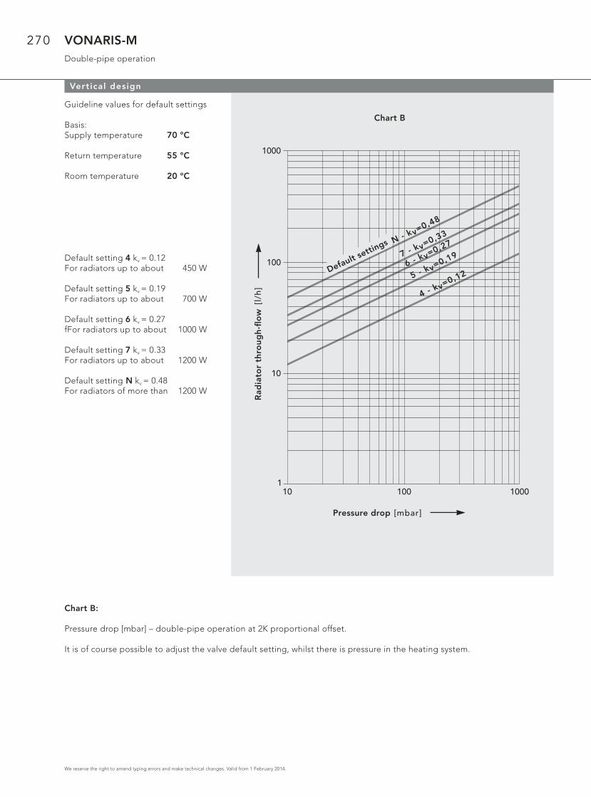
Vertical design
Guideline values for default settings
Basis:Supply temperature 70 °C
Return temperature 55 °C
Room temperature 20 °C
Default setting 4 kv = 0.12For radiators up to about 450 W
Default setting 5 kv = 0.19For radiators up to about 700 W
Default setting 6 kv = 0.27fFor radiators up to about 1000 W
Default setting 7 kv = 0.33For radiators up to about 1200 W
Default setting N kv = 0.48For radiators of more than 1200 W
Chart B:
Pressure drop [mbar] – double-pipe operation at 2K proportional offset.
It is of course possible to adjust the valve default setting, whilst there is pressure in the heating system.
Chart B
Rad
iato
r th
rou
gh
-fl o
w
Pressure drop
Default settin
gs
271
We reserve the right to amend typing errors and make technical changes. Valid from 1 February 2014.
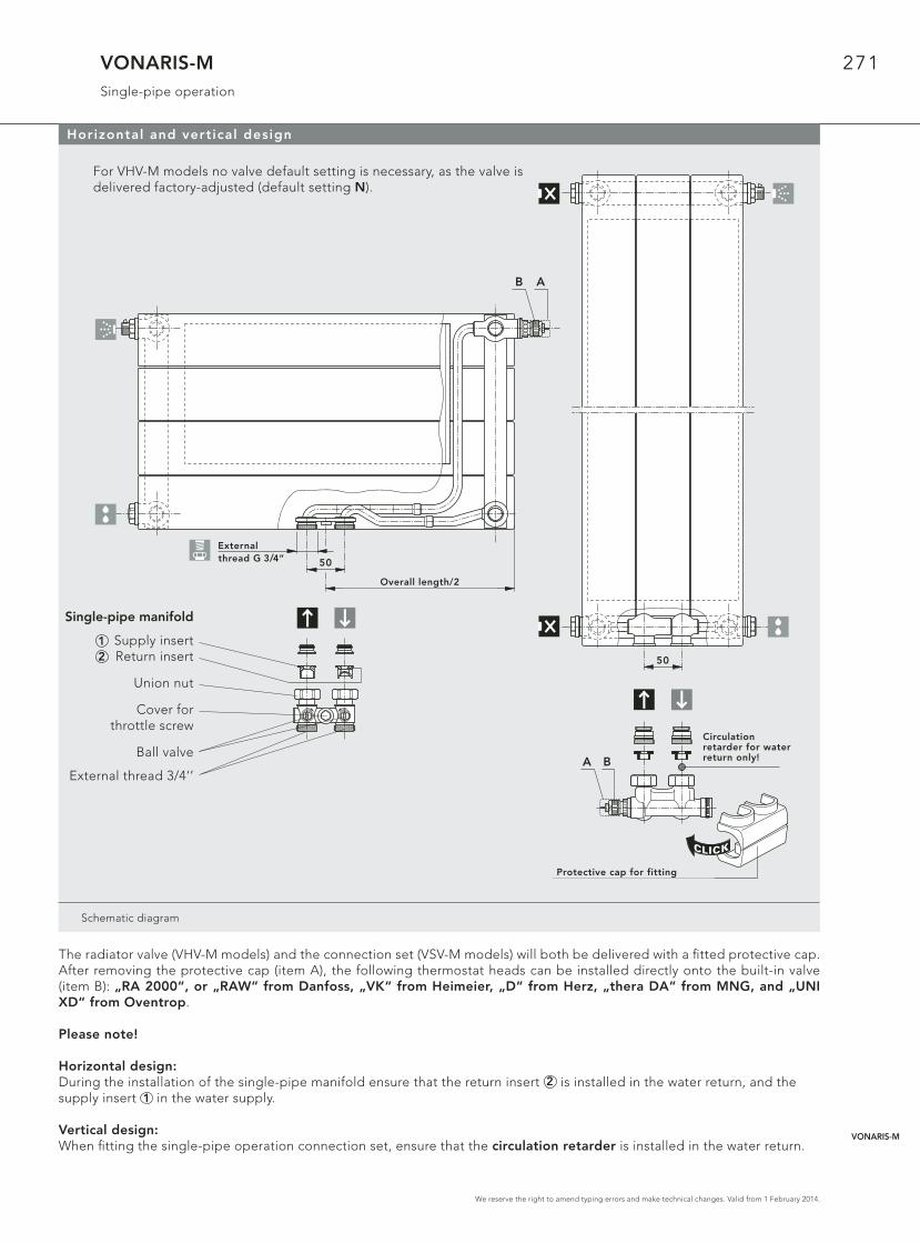
VONARIS-MSingle-pipe operation
Schematic diagram
50
N
CLICK
Armaturen-Abdeckkappe
Zirkulations-bremse nurim Rücklauf!A B
Horizontal and vertical design
For VHV-M models no valve default setting is necessary, as the valve is delivered factory-adjusted (default setting N).
The radiator valve (VHV-M models) and the connection set (VSV-M models) will both be delivered with a fi tted protective cap. After removing the protective cap (item A), the following thermostat heads can be installed directly onto the built-in valve (item B): „RA 2000“, or „RAW“ from Danfoss, „VK“ from Heimeier, „D“ from Herz, „thera DA“ from MNG, and „UNI XD“ from Oventrop.
Please note!
Horizontal design: During the installation of the single-pipe manifold ensure that the return insert 2 is installed in the water return, and the supply insert 1 in the water supply.
Vertical design: When fi tting the single-pipe operation connection set, ensure that the circulation retarder is installed in the water return.
50
G 3/4" A. G.N
Baulänge/2
B A
12
Single-pipe manifold
Supply insertReturn insert
Union nut
Cover forthrottle screw
Ball valve
External thread 3/4‘’
External thread G 3/4“
Overall length/2
Circulation retarder for water return only!
Protective cap for fitting
VONARIS-M
272
We reserve the right to amend typing errors and make technical changes. Valid from 1 February 2014.
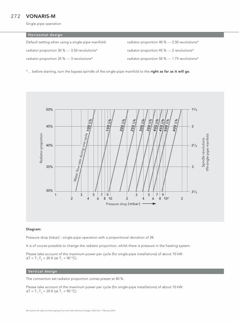
VONARIS-MSingle-pipe operation
Horizontal design
2
Druckverlust [mbar]
1 34
56 8 10
7 92
3 5 7 94 6 8 102 2
31/2
3
21/2
2
13/4
Sp
ind
elv
erd
reh
un
ge
nV
N E
inro
hrv
ert
eil
er
He
izkö
rpe
ran
teil
30%
35%
40%
45%
50%
Kre
isw
asse
rdu
rch
flu
ss 1
00
l/h
15
0 l
/h
25
0 l
/h
20
0 l
/h
30
0 l
/h3
50
l/h
40
0 l
/h4
50
l/h
50
0 l
/h
60
0 l
/h
Default setting when using a single-pipe manifold:
radiator proportion 30 % --- 3.50 revolutions*
radiator proportion 35 % --- 3 revolutions*
radiator proportion 40 % --- 2.50 revolutions*
radiator proportion 45 % --- 2 revolutions*
radiator proportion 50 % --- 1.75 revolutions*
*… before starting, turn the bypass spindle of the single-pipe manifold to the right as far as it will go.
Diagram:
Pressure drop [mbar] – single-pipe operation with a proportional deviation of 2K.
It is of course possible to change the radiator proportion, whilst there is pressure in the heating system.
Please take account of the maximum power per cycle (for single-pipe installations) of about 10 kW:ΔT = T1-T2 = 20 K (at T1 = 90 °C).
Vertical design
The connection set radiator proportion comes preset at 40 %.
Please take account of the maximum power per cycle (for single-pipe installations) of about 10 kW:ΔT = T1-T2 = 20 K (at T1 = 90 °C).
Pressure drop
Rad
iato
r p
rop
ortio
n
Spin
dle
revo
lutio
nsV
N-s
ing
le-p
ipe
man
ifold
Wat
er fl
ow ra
te d
urin
g on
e cy
cle

273
We reserve the right to amend typing errors and make technical changes. Valid from 1 February 2014.
VONARIS-M Wall mounting WA 11welded bracket postions
Wall mounting WA 11 for models VHV-M 10, VHV-M 11, VHV-M 20, VHV-M 22 und VHV-M 34
Model VHV-M 10 / 11 für Wandaufhängung WA 11
Overallheight
358 mm
VHV-M 22 bzw. VHV-M 34 für Wandaufhängung WA 11
Overallheight
214 mmund
286 mm
VHV-M 10 / 11, VHV-M 20/22 für Wandaufhängung WA 11
Overallheight
430 mmbis
574 mmVHV-M 10/11,
358 mmbis
502 mmVHV-M20/22
VHV-M 10 / 11, VHV-M 20/22 für Wandaufhängung WA 11
Overallheight
646 mmbis
790 mmVHV-M 10/11,
574 mmbis
790 mmVHV-M 20/22
Schematic diagram
Attention! With the horizontal design only the models VHV-M 10/11 (OH 358 - 790 mm) are by default supplied with brackets. If the models VHV-M 20 (OH 358 - 790 mm), VHV-M 22 (OH 214 - 790) and VHV-M 34 (142 – 286 mm) are wall-mounted using wall mounting WA 11, you are required to order these models as a special version, equipped with brackets.
13
01
20
500 - 2000
160 160
130
120
160 160
2200 - 2400
1/2 1/2
500 - 2000
160 160
85
12
0
160 1601/2 1/2
2200 - 2400
85
120
13
02
20
500 - 2000
160 160
130
220
160 160
2200 - 2400
1/2 1/2
60
14
60
14
13
04
20
500 - 2000
160 160
40
13
04
20
160 160
2200 - 240040
1/2 1/2
VHV-M 22 VHV-M 11
VONARIS-M

274
We reserve the right to amend typing errors and make technical changes. Valid from 1 February 2014.
VONARIS-M Wall mounting WA 11drilling measurements and wall-clearance
Wall mounting WA 11 for models VHV-M 10, VHV-M 11, VHV-M 20, VHV-M 22 und VHV-M 34
Wall mounting WA 11 is suitable for the horizontal versions of the following models: VHV-M 10 (OH 358 - 790 mm), VHV-M 11(OH 358 - 790 mm), VHV-M 20 (BH 358 - 790 mm), VHV-M 22 (OH 214 - 790 mm) and VHV-M 34 (OH 214 and 286 mm) equipped with brackets. It ensures easy, rapid and robust mounting of the VONARIS central-connection radiators still in the packaging.
Wall mounting WA 11 for OH 214 - 790
Dri l l ing measurements for the Wandaufhängung WA 11
From an overal l length of 2200 mm: 3 consoles
ModelVHV-MOverall height [mm]
Value X [mm]
Value Y [mm]
Value Z [mm]
Wall mounting WA 11
VHV-M 22, 34 214 104 162 52
VHV-M 22, 34 286 176 234 52
VHV-M 10, 11 358 203 261 97
VHV-M 20, 22 358 203 261 97
VHV-M 10, 11, 20, 22 430 275 333 97
VHV-M 10, 11, 20, 22 502 347 405 97
VHV-M 10, 11 574 419 477 97
VHV-M 20, 22 574 419 477 97
VHV-M 10, 11, 20, 22 646 491 549 97
VHV-M 10, 11, 20, 22 718 563 621 97
VHV-M 10, 11, 20, 22 790 635 693 97
Schematic diagram
Connection – wall c learance
Horizontal design modelOveral l
height [mm]Value W [mm]
VHV-M 10 358 - 790 45
VHV-M 11 358 - 790 45
VHV-M 20 358 - 790 89
VHV-M 22 214 - 790 89
VHV-M 34 214 / 286 89
Schematic diagram
HeizkörperOberkante
HeizkörperUnterkante
XY
Z
W
Radiator topedge
Radiator lower edge

275
We reserve the right to amend typing errors and make technical changes. Valid from 1 February 2014.
VONARIS-M VONOFIXbracket positioning for insertion (push-in) brackets
VONOFIX rapid-instal lation console for the VHV-M models
VHV-M 10 models: OH 358 - 790 mm, VHV-M 20 models: OH 358 - 790 mm,VHV-M 22 models: OH 214 - 790 mm and VHV-M 34 models: OH 214 and 286 mm
OH 214: for VONOFIX 1 OH 574 and 646: for VONOFIX 4
OH 286 and 358: for VONOFIX 2
OH 430 and 502: for VONOFIX 3 OH 718 and OH 790: for VONOFIX 5
Schematic diagram
21
5
BH
28
6
21
5
7070
BH
35
8
14
3
7070
BH
21
4
50
3
BH
57
4
50
3
7070
BH
64
6
35
9
BH
43
0
BL 2200 und 2400
1/2 Baulänge + 100 mm
35
9
7070
BH
50
2
647
7070
BL 500 - 2000
40
BH
790
Important: the installation of VHV-M models with insertion (push-in) brackets is only feasible when using the VONOFIX rapid-installation console!
Note! for an overall length of 2200 mm and greater an additional piece of foot con-sole must be used!
647
7070
BL 500 - 2000
BH
718
VONARIS-M

276
We reserve the right to amend typing errors and make technical changes. Valid from 1 February 2014.
VONARIS-M VONOFIXdrilling measurements and wall clearance
VONOFIX rapid-instal lation console for the VHV-M models
The VONARIS central connection radiator can be installed easily, quickly and securely. This is made possible by the VONO-FIX rapid-installation console for the horizontal designs of the VHV-M 20 (OH 358 - 790 mm), VHV-M 22 (OH 214 - 790 mm) and the VHV-M 34 (OH 214 and 286 mm) models.
Wall rai ls for OH 214 – 790 mm
Dri l l ing measurements for the VONOFIX 1 - 5
Overall radiatorheight [mm]
Value X [mm] Value Y [mm] Value Z [mm]
214 – 125 89
286 100 197 89
358 100 197 161
430 100 341 89
502 100 341 161
574 100 485 89
646 100 485 161
718 100 629 89
790 100 629 161
Schematic diagram
X
Heizkörper Oberkante
HeizkörperUnterkante
YZ
Connection – wall c learance
Horizontal design modelOveral l
height [mm]Value W [mm]
VHV-M 20 358 – 790 91
VHV-M 22 214 – 790 91
VHV-M 34 214 – 286 91*
* Note: i f the VHV-M 34 is turned round and used as a left-hand design model, the measurement W is 172 mm.
Schematic diagram
W
The VONOFIX rapid-installation console consists of: 2 wall consoles (zinc-plated), with sound-proofi ng fi lters, screws and dowels 2 stabilising brackets 2 insertion (push-in) brackets (For an overall length of 2200 mm and greater, 1 additional piece of foot console)
Radiator top edge
Radiator lower edge

277
We reserve the right to amend typing errors and make technical changes. Valid from 1 February 2014.
VONARIS-Mwelded brackets positions
VSV-M models
Overal length
[mm]
214 286 358 430 - 862
Schematic diagram
60
48
60
14
VSV-M 2060
14
VSV-M 2160
14
VSV-M 10 VSV-M 11 VSV-M 20 VSV-M 21
Wall c learance measurements: WA 10 and WA 11 wall mounting brackets for the VSV-M models
Connection – wall c learance
Wall mounting brackets model
Vertical design model Value W [mm]
WA 10 VSV-M 10/11* 35
WA 10 VSV-M 20/21 79,5
WA 11 VSV-M 10/11* 45
WA 11 VSV-M 20/21 89,5
*Note! i f you are using WA 10 or WA 11 wal l mounting brackets for the instal la-t ion of the VSV-M 10 or VSV-M 11 model with a r ight-angled-design connect ion, please fol low the instruct ions in the diagram on page 267.
Schematic diagram
W
BL 430 - 862
16
00
, 1
80
0,
20
00
13
0
107107
90
40
16
00
, 1
80
0,
20
00
13
09
0
214
40
286
7171
16
00
, 1
80
0,
20
00
13
09
0
40
358
7171
16
00
, 1
80
0,
20
00
13
09
0
40
VONARIS-M
278
We reserve the right to amend typing errors and make technical changes. Valid from 1 February 2014.
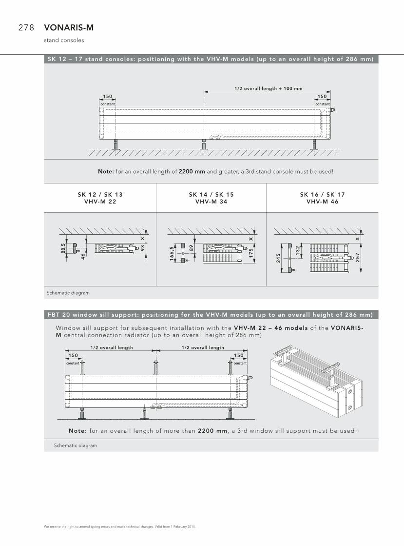
VONARIS-Mstand consoles
FBT 20 window si l l support: posit ioning for the VHV-M models (up to an overal l height of 286 mm)
Window si l l support for subsequent instal lat ion with the VHV-M 22 – 46 models of the VONARIS-M central connect ion radiator (up to an overal l height of 286 mm)
Note: for an overal l length of more than 2200 mm , a 3rd window si l l support must be used!
Schematic diagram
150 150
fix fix
Baulänge1/2 Baulänge1/2
SK 12 – 17 stand consoles: posit ioning with the VHV-M models (up to an overal l height of 286 mm)
Note: for an overall length of 2200 mm and greater, a 3rd stand console must be used!
SK 12 / SK 13VHV-M 22
SK 14 / SK 15VHV-M 34
SK 16 / SK 17VHV-M 46
Schematic diagram
150 150
fix fix
Baulänge + 100 mm1/2
X
88,5
93
46
16
6,5 8
9
X1
75
24
5 13
2
X2
57
1/2 overall length + 100 mm
constant constant
1/2 overall length 1/2 overall length
constant constant

279
We reserve the right to amend typing errors and make technical changes. Valid from 1 February 2014.
VONARIS-MWall mounting
Wall mounting posit ions VONARIS-M
Attention: i f more than 2 wal l consoles are used, any addit ional wal l consoles are to be used at regu-lar distances f rom each other along a length of X.
150 150X
fix fix
WK 10-MVHV-M 22
WK 11-MVHV-M 34
WK 12VHV-M 46
Schematic diagram
2511
5
93
25
19
7
17
5
25
27
9
25
7
constant constant
VONARIS-M

280
We reserve the right to amend typing errors and make technical changes. Valid from 1 February 2014.
VONARIS-Mheating outputs
Heating output in compliance with DIN EN 442, and ÖNORM EN 442, at 75/65/20° C
Side panels and top cover are included in the heat output specifi cations
Overall height [mm]
214 286 358 430 502 574 646 718 790
Increments As regards all overall lengths between 500 and 1400 mm, use increments of 100 mm, and overall lengths between 1600 and 2400 mm, use increments of 200 mm.
Model VHV-M 10* VHV-M 10* VHV-M 10* VHV-M 10* VHV-M 10* VHV-M 10* VHV-M 10*
Overall depth [mm]
68 68 68 68 68 68 68
Watts / m 75/65/20 394 458 523 588 655 720 795
Watts / m 70/55/20 322 374 427 480 534 590 647
Watts / m 55/45/20 209 243 276 311 344 380 416
Water content l / m 2,76 3,33 3,87 4,44 4,99 5,55 6,12
Weight kg / m 11,91 14,04 16,17 18,29 20,43 22,60 24,68
Radiator exponent n 1,24 1,24 1,25 1,25 1,26 1,26 1,27
Model VHV-M 11* VHV-M 11* VHV-M 11* VHV-M 11* VHV-M 11* VHV-M 11* VHV-M 11*
Overall depth [mm]
68 68 68 68 68 68 68
Watts / m 75/65/20 625 718 804 886 965 1043 1105
Watts / m 70/55/20 505 583 652 717 781 844 889
Watts / m 55/45/20 320 372 415 456 497 537 558
Water content l / m 2,78 3,33 3,87 4,44 4,99 5,55 6,12
Weight kg / m 16,71 19,85 22,99 26,15 29,29 31,42 33,55
Radiator exponent n 1,31 1,29 1,29 1,30 1,30 1,30 1,34
Model VHV-M 20 VHV-M 20 VHV-M 20 VHV-M 20 VHV-M 20 VHV-M 20 VHV-M 20
Overall depth [mm]
93 93 93 93 93 93 93
Watts / m 75/65/20 654 757 859 960 1063 1166 1271
Watts / m 70/55/20 533 617 699 781 864 947 1032
Watts / m 55/45/20 344 397 450 501 554 607 660
Water content l / m 5,55 6,66 7,77 8,88 9,99 11,10 12,22
Weight kg / m 21,29 25,30 29,31 33,31 37,32 41,32 45,33
Radiator exponent n 1,26 1,26 1,27 1,27 1,28 1,28 1,28
Model VHV-M 22 VHV-M 22 VHV-M 22 VHV-M 22 VHV-M 22 VHV-M 22 VHV-M 22 VHV-M 22 VHV-M 22
Overall depth [mm]
93 93 93 93 93 93 93 93 93
Watts / m 75/65/20 769 938 1100 1268 1405 1534 1654 1767 1886
Watts / m 70/55/20 621 756 885 1021 1130 1232 1326 1414 1500
Watts / m 55/45/20 393 477 555 642 708 769 825 877 919
Water content l / m 3,34 4,44 5,55 6,66 7,77 8,88 9,99 11,11 12,22
Weight kg / m 20,59 27,23 30,89 36,93 42,96 49,01 55,05 59,05 63,06
Radiator exponent n 1,31 1,32 1,34 1,33 1,34 1,35 1,36 1,37 1,41
* For aesthetic reasons these models should not be fi tted in front of a window.

281
We reserve the right to amend typing errors and make technical changes. Valid from 1 February 2014.
VONARIS-Mheating outputs
Overall height [mm]
214 286
IncrementsAs regards all overall lengths between 500 and 1400 mm, use increments of 100 mm, and overall lengths between 1600 and
2400 mm, use increments of 200 mm.
Model VHV-M S 22 VHV-M S 22
Overall depth [mm]
163 163
Watts / m 75/65/20 769 938
Watts / m 70/55/20 621 756
Watts / m 55/45/20 393 477
Water content l / m 3,34 4,44
Weight kg / m 28,34 37,24
Radiator exponent n 1,31 1,32
* For aesthetic reasons these models should not be fi tted in front of a window.
Overall height [mm]
142 214 286
IncrementsAs regards all overall lengths between 500 and 1400 mm, use increments of 100 mm, and overall lengths between 1600 and
2400 mm, use increments of 200 mm.
Model VHV-M 34 VHV-M 34 VHV-M 34
Overall depth [mm]
175 175 175
Watts / m 75/65/20 953 1357 1616
Watts / m 70/55/20 773 1094 1296
Watts / m 55/45/20 493 690 808
Water content l / m 3,33 4,99 6,66
Weight kg / m 23,93 35,18 46,42
Radiator exponent n 1,29 1,32 1,36
Model VHV-M 46 VHV-M 46 VHV-M 46
Overall depth [mm]
257 257 257
Watts / m 75/65/20 1433 1895 2357
Watts / m 70/55/20 1160 1525 1885
Watts / m 55/45/20 738 957 1168
Water content l / m 4,53 6,79 9,06
Weight kg / m 33,89 49,76 65,62
Radiator exponent n 1,30 1,34 1,37
Model VHV-M S 46 VHV-M S 46 VHV-M S 46
Overall depth [mm]
327 327 327
Watts / m 75/65/20 1433 1895 2357
Watts / m 70/55/20 1160 1525 1885
Watts / m 55/45/20 738 957 1168
Water content l / m 4,53 6,79 9,06
Weight kg / m 39,35 57,50 75,64
Radiator exponent n 1,30 1,34 1,37
* For aesthetic reasons these models should not be fi tted in front of a window.
Heating output in compliance with DIN EN 442, and ÖNORM EN 442, at 75/65/20° C
Side panels and top cover are included in the heat output specifi cations
VONARIS-M
282
We reserve the right to amend typing errors and make technical changes. Valid from 1 February 2014.
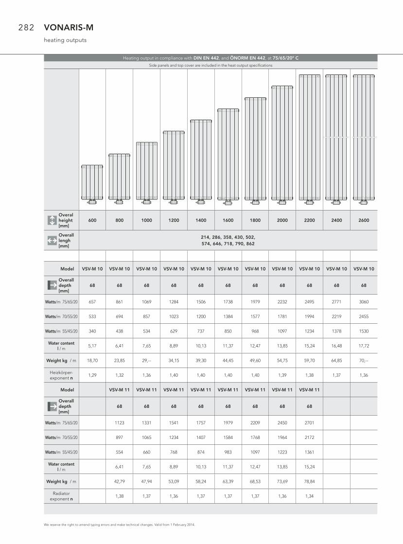
VONARIS-Mheating outputs
Overal height [mm]
600 800 1000 1200 1400 1600 1800 2000 2200 2400 2600
Overall lengh [mm]
214, 286, 358, 430, 502, 574, 646, 718, 790, 862
Model VSV-M 10 VSV-M 10 VSV-M 10 VSV-M 10 VSV-M 10 VSV-M 10 VSV-M 10 VSV-M 10 VSV-M 10 VSV-M 10 VSV-M 10
Overall depth[mm]
68 68 68 68 68 68 68 68 68 68 68
Watts/m 75/65/20 657 861 1069 1284 1506 1738 1979 2232 2495 2771 3060
Watts/m 70/55/20 533 694 857 1023 1200 1384 1577 1781 1994 2219 2455
Watts/m 55/45/20 340 438 534 629 737 850 968 1097 1234 1378 1530
Water content l / m
5,17 6,41 7,65 8,89 10,13 11,37 12,47 13,85 15,24 16,48 17,72
Weight kg / m 18,70 23,85 29,-- 34,15 39,30 44,45 49,60 54,75 59,70 64,85 70,--
Heizkörper-exponent n
1,29 1,32 1,36 1,40 1,40 1,40 1,40 1,39 1,38 1,37 1,36
Model VSV-M 11 VSV-M 11 VSV-M 11 VSV-M 11 VSV-M 11 VSV-M 11 VSV-M 11 VSV-M 11
Overall depth[mm]
68 68 68 68 68 68 68 68
Watts/m 75/65/20 1123 1331 1541 1757 1979 2209 2450 2701
Watts/m 70/55/20 897 1065 1234 1407 1584 1768 1964 2172
Watts/m 55/45/20 554 660 768 874 983 1097 1223 1361
Water content l / m
6,41 7,65 8,89 10,13 11,37 12,47 13,85 15,24
Weight kg / m 42,79 47,94 53,09 58,24 63,39 68,53 73,69 78,84
Radiator exponent n
1,38 1,37 1,36 1,37 1,37 1,37 1,36 1,34
Heating output in compliance with DIN EN 442, and ÖNORM EN 442, at 75/65/20° C
Side panels and top cover are included in the heat output specifi cations
283
We reserve the right to amend typing errors and make technical changes. Valid from 1 February 2014.
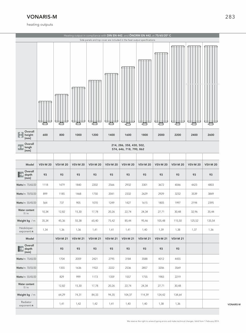
VONARIS-Mheating outputs
Overallheight [mm]
600 800 1000 1200 1400 1600 1800 2000 2200 2400 2600
Overall lengh [mm]
214, 286, 358, 430, 502, 574, 646, 718, 790, 862
Model VSV-M 20 VSV-M 20 VSV-M 20 VSV-M 20 VSV-M 20 VSV-M 20 VSV-M 20 VSV-M 20 VSV-M 20 VSV-M 20 VSV-M 20
Overall depth[mm]
93 93 93 93 93 93 93 93 93 93 93
Watts/m 75/65/20 1118 1479 1840 2202 2566 2932 3301 3672 4046 4423 4803
Watts/m 70/55/20 899 1185 1468 1750 2041 2332 2629 2929 3232 3539 3849
Watts/m 55/45/20 564 737 905 1070 1249 1427 1615 1805 1997 2194 2395
Water content l / m
10,34 12,82 15,30 17,78 20,26 22,74 24,34 27,71 30,48 32,96 35,44
Weight kg / m 35,34 45,36 55,38 65,40 75,42 85,44 95,46 105,48 115,50 125,52 135,54
Heizkörper-exponent n
1,34 1,36 1,36 1,41 1,41 1,41 1,40 1,39 1,38 1,37 1,36
Model VSV-M 21 VSV-M 21 VSV-M 21 VSV-M 21 VSV-M 21 VSV-M 21 VSV-M 21 VSV-M 21
Overall depth[mm]
93 93 93 93 93 93 93 93
Watts/m 75/65/20 1704 2059 2421 2795 3184 3588 4012 4455
Watts/m 70/55/20 1355 1636 1922 2222 2536 2857 3206 3569
Watts/m 55/45/20 829 999 1173 1359 1557 1755 1983 2219
Water content l / m
12,82 15,30 17,78 20,26 22,74 24,34 27,71 30,48
Weight kg / m 64,29 74,31 84,33 94,35 104,37 114,39 124,42 134,64
Radiator exponent n
1,41 1,42 1,42 1,41 1,40 1,40 1,38 1,36
Heating output in compliance with DIN EN 442, and ÖNORM EN 442, at 75/65/20° C
Side panels and top cover are included in the heat output specifi cations
VONARIS-M
284
We reserve the right to amend typing errors and make technical changes. Valid from 1 February 2014.
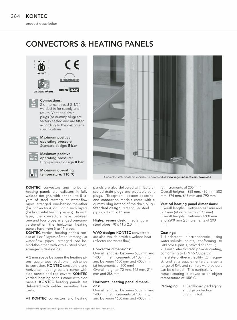
KONTECproduct description
CONVECTORS & HEATING PANELS
KONTEC convectors and horizontal heating panels are radiators in fully welded designs, with either 1 to 5 la-yers of steel rectangular water-fl ow pipes arranged one-behind-the-other (for convectors), or 1 or 2 such layers (for horizontal heating panels). In each layer, the convectors have between one and four pipes arranged one-abo-ve-the-other; the horizontal heating panels have from 5 to 11 pipes.KONTEC vertical heating panels con-sist of 1 or 2 layers of steel rectangular water-fl ow pipes, arranged one-be-hind-the-other, with 2 to 12 steel pipes, arranged side-by-side.
A 2 mm space between the heating pi-pes guarantees additional resistance to corrosion. KONTEC convectors and horizontal heating panels come with side panels and top covers; KONTEC vertical heating panels come with side panels. KONTEC heating panels are delivered with welded mounting bra-ckets.
All KONTEC convectors and heating
panels are also delivered with factory-sealed drain plugs and pivotable vent plugs. (Exception: bottom-opposite-end connection models come with a dummy plug instead of the drain plug.) Standard design: rectangular steel pipes, 70 x 11 x 1.5 mm
High-pressure design: rectangular steel pipes, 70 x 11 x 2.0 mm
WVO-design: KONTEC convectors are also available with a welded heat refl ector (no water-fl ow).
Convector dimensions:Overall lengths: between 500 mm and 1400 mm (at increments of 100 mm), and between 1600 mm and 4000 mm (at increments of 200 mm)Overall heights: 70 mm, 142 mm, 214 mm and 286 mm
Horizontal heating panel dimensi-ons:Overall lengths: between 500 mm and 1400 mm (at increments of 100 mm), and between 1600 mm and 4000 mm
(at increments of 200 mm)Overall heights: 358 mm, 430 mm, 502 mm, 574 mm, 646 mm and 790 mm
Vertical heating panel dimensions:Overall lengths: between 142 mm and 862 mm (at increments of 72 mm)Overall heights: between 1600 mm and 2200 mm (at increments of 200 mm)
Coatings:1. Undercoat: electrophoretic, using water-soluble paints, conforming to DIN 55900 part 1, stoved at 165° C; 2. Finish: electrostatic powder coating, conforming to DIN 55900 part 2, in a state-of-the-art facility. (On reque-st, and at a supplementary charge, a range of RAL and sanitary ware colours can be offered.) This particularly robust coating is stoved at an object temperature of 180° C.
Packaging: 1. Cardboard packaging 2. Edge protection 3. Shrink foil
max
.
5 barmax.
8 barmax.
Guarantee statements are available to download at www.vogelundnoot.com/download
Connections:2 x internal thread G 1/2“, welded-in for supply and return. Vent and drain plugs (or dummy plug) are factory sealed and are fi tted according to the customer’s specifi cations.
Maximum positive operating pressureStandard design: 5 bar
Maximum positive operating pressure: High-pressure design 8 bar
Maximum operating temperature: 110 °C
285
We reserve the right to amend typing errors and make technical changes. Valid from 1 February 2014.
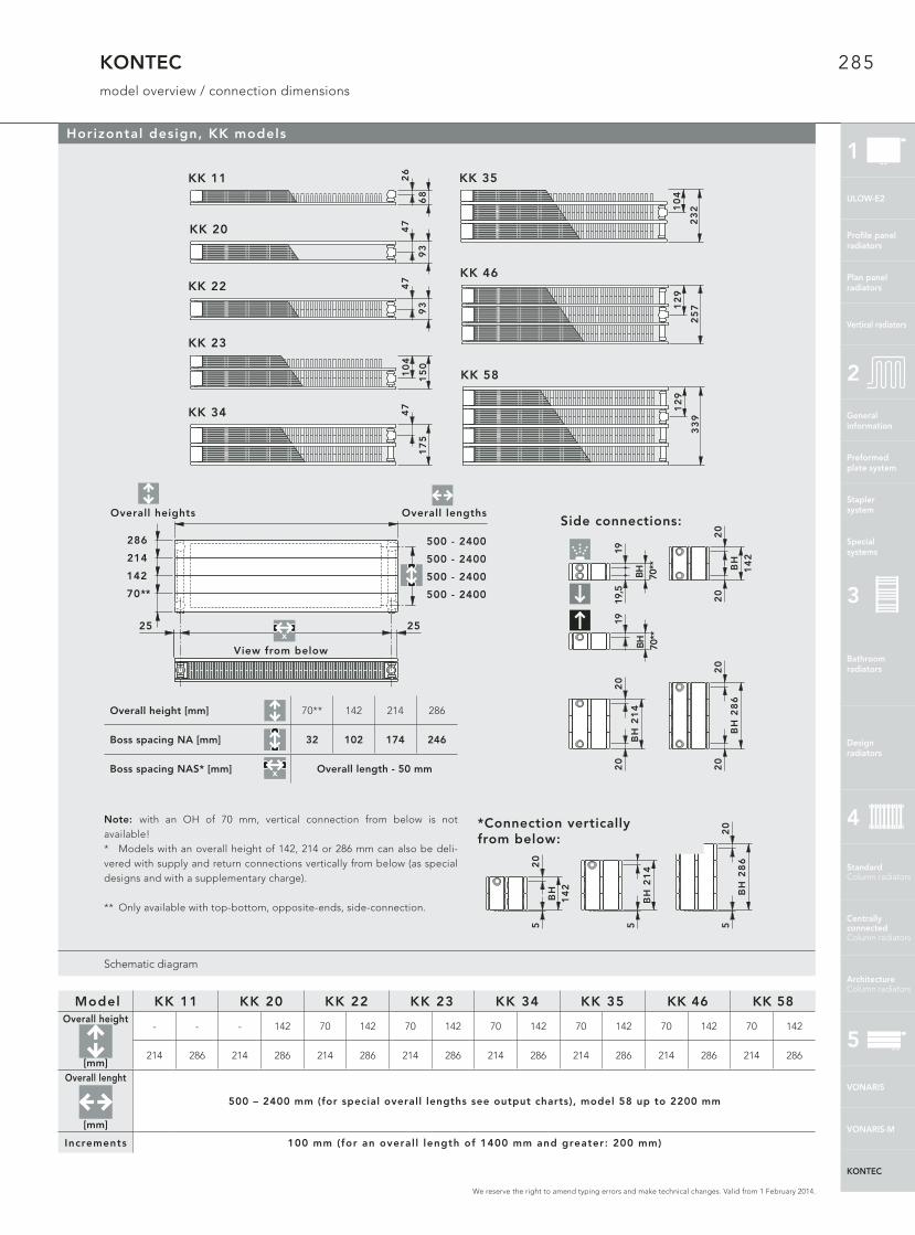
KONTECmodel overview / connection dimensions
Schematic diagram
Horizontal design, KK models
Model KK 11 KK 20 KK 22 KK 23 KK 34 KK 35 KK 46 KK 58Overall height
[mm]
- - - 142 70 142 70 142 70 142 70 142 70 142 70 142
214 286 214 286 214 286 214 286 214 286 214 286 214 286 214 286
Overall lenght
[mm]
500 – 2400 mm (for special overall lengths see output charts), model 58 up to 2200 mm
Increments 100 mm (for an overal l length of 1400 mm and greater: 200 mm)
20
20
BH
28
6
Anschlüsse seitlich:
20
20
BH
21
4
20
20
BH
14
2
19
BH
70*
*
1919
,5
BH
70*
*
Anschlüsse senkrechtnach unten: 2
05
BH
28
6
20
BH
21
4
5
20
5
BH
14
2
*Anschlüsse senkrecht nach unten:Note: with an OH of 70 mm, vertical connection from below is not available!* Models with an overall height of 142, 214 or 286 mm can also be deli-vered with supply and return connections vertically from below (as special designs and with a supplementary charge).
** Only available with top-bottom, opposite-ends, side-connection.
KK 46
25
712
9
KK 341
75
47
KK 58
12
9
33
9
KK 23
15
0
10
4
KK 35
23
210
4
KK 11 26
68
KK 22 47
93
KK 20 47
93
Overall height [mm] 70** 142 214 286
Boss spacing NA [mm] 32 102 174 246
Boss spacing NAS* [mm] Overall length - 50 mmx
View from below
Overall heights
142
214
286
70**
500 - 2400
500 - 2400
500 - 2400
500 - 2400
25 25
Overall lengths
x
Side connections:
*Connection verticallyfrom below:
1
VONARIS
VONARIS-M
KONTEC
ULOW-E2
Profi le panelradiators
Plan panelradiators
Vertical radiators
Generalinformation
Preformed plate system
Stapler system
Special systems
2
Bathroom radiators
Design radiators
3
Standard Column radiators
Centrallyconnected Column radiators
Architecture Column radiators
4
5

286
We reserve the right to amend typing errors and make technical changes. Valid from 1 February 2014.
KONTECWVO design
Schematic diagram
The KK-S models
With their factory-welded heat refl ector (no water-fl ow), the WVO designs return a major part of the otherwise lost heat to the room. They do so by means of convection between radiator and heat refl ector.
Model KK-S 22 KK-S 34 KK-S 47Overall height
[mm]
70 142 214 286 70 142 214 286 70 142 214 286
Overall length
[mm]
500 – 2400 mm (for special overall lengths see output charts)
Increments 100 mm (for an overal l length of 1400 mm and greater: 200 mm)
Overall height [mm] 70** 142 214 286
Boss spacing NA [mm] 32 102 174 246
Boss spacing NAS* [mm] Overall length - 50 mm
Model overview / connection dimensions: KK-S models, horizontal design
Note: with an OH of 70 mm, vertical connection from below is not available!
* Models with an overall height of 142, 214 or 286 mm can also be delivered with supply and return connections vertically from below (as special designs and with a supplementary charge). ** Only available with top-bottom, opposite-ends, side-connection.
x
x
19
OH
70*
*
1919
,5
OH
70*
**Connection vertically from below:
View from below
Overall heights
142
214
286
70**
500 - 2400
500 - 2400
500 - 2400
500 - 2400
Side connections:
20
20
OH
28
6
20
20
OH
21
4
20
20
OH
14
2
20
5
OH
28
6
25 25
20
OH
21
4
5
OH
14
2
20
5
KK-S 22
16
3
11
7
KK-S 34
24
511
7
KK-S 47
32
719
9
Overall lengths
287
We reserve the right to amend typing errors and make technical changes. Valid from 1 February 2014.
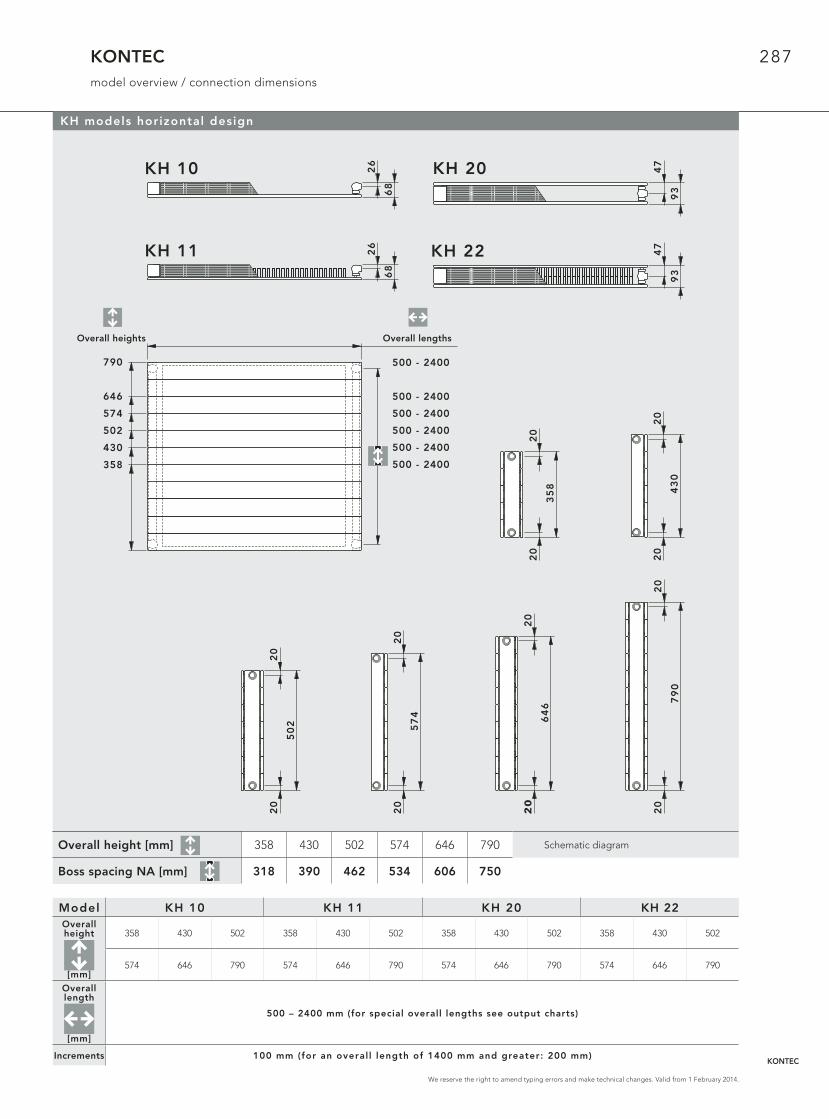
KONTECmodel overview / connection dimensions
Schematic diagram
KH models horizontal design
Model KH 10 KH 11 KH 20 KH 22Overall height
[mm]
358 430 502 358 430 502 358 430 502 358 430 502
574 646 790 574 646 790 574 646 790 574 646 790
Overall length
[mm]
500 – 2400 mm (for special overall lengths see output charts)
Increments 100 mm (for an overal l length of 1400 mm and greater: 200 mm)
Overall height [mm] 358 430 502 574 646 790
Boss spacing NA [mm] 318 390 462 534 606 750
20
20
79
0
KH 10 26
68
KH 11 26
68
KH 22 47
93
20
20
43
0
20
20
50
2
20
20
35
8
20
20
57
4
20
20
64
6
KH 20 47
93
Bauhöhen
500 - 2400
500 - 2400
500 - 2400
500 - 2400
500 - 2400
500 - 2400358
430
502
574
646
790
BaulängenOverall heights Overall lengths
KONTEC

288
We reserve the right to amend typing errors and make technical changes. Valid from 1 February 2014.
KONTECmodel overview / connection dimensions
Schematic diagram
KS models vertical design
Model KS 10 KS 11 KS 20 KS 21Overall height
[mm]
1600 1800 1600 1800 1600 1800 1600 1800
2000 2200 2000 2200 2000 2200 2000 2200
Overall length
[mm]
142 - 862 mm
Increments 72 mm
Overall height [mm] 1600 1800 2000 2200
Boss spacing NA [mm] 1550 1750 1950 2150
KS 10
KS 20
KS 11
KS 2147
93
26
68
47
93
26
68
KS
10
68 68
KS
11
93
KS
20
93
KS
21
16
00
, 1
80
0,
20
00
, 2
20
0
142 - 862
55 55
55 55
289
We reserve the right to amend typing errors and make technical changes. Valid from 1 February 2014.
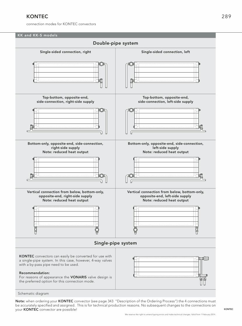
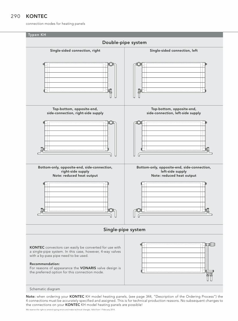
Double-pipe system
Single-sided connection, right Single-sided connection, left
Top-bottom, opposite-end, side-connection, right-side supply
Top-bottom, opposite-end,side-connection, left-side supply
Bottom-only, opposite-end, side-connection, right-side supply
Note: reduced heat output
Bottom-only, opposite-end, side-connection, left-side supply
Note: reduced heat output
Vertical connection from below, bottom-only, opposite-end, right-side supply
Note: reduced heat output
Vertical connection from below, bottom-only, opposite-end, left-side supply
Note: reduced heat output
Single-pipe system
KONTEC convectors can easily be converted for use with a single-pipe system. In this case, however, 4-way valves with a by-pass pipe need to be used.
Recommendation: For reasons of appearance the VONARIS valve design is the preferred option for this connection mode.
Schematic diagram
KONTECconnection modes for KONTEC convectors
KK and KK-S models
Note: when ordering your KONTEC convector (see page 343 “Description of the Ordering Process“) the 4 connections must be accurately specifi ed and assigned. This is for technical production reasons. No subsequent changes to the connections on your KONTEC convector are possible! KONTEC
290
We reserve the right to amend typing errors and make technical changes. Valid from 1 February 2014.
Double-pipe system
Single-sided connection, right Single-sided connection, left
Top-bottom, opposite-end, side-connection, right-side supply
Top-bottom, opposite-end,side-connection, left-side supply
Bottom-only, opposite-end, side-connection, right-side supply
Note: reduced heat output
Bottom-only, opposite-end, side-connection, left-side supply
Note: reduced heat output
Single-pipe system
KONTEC convectors can easily be converted for use with a single-pipe system. In this case, however, 4-way valves with a by-pass pipe need to be used.
Recommendation: For reasons of appearance the VONARIS valve design is the preferred option for this connection mode.
Schematic diagram
KONTECconnection modes for heating panels
Typen KH
Note: when ordering your KONTEC KH model heating panels, (see page 344, “Description of the Ordering Process”) the 4 connections must be accurately specifi ed and assigned. This is for technical production reasons. No subsequent changes to the connections on your KONTEC KH model heating panels are possible!

291
We reserve the right to amend typing errors and make technical changes. Valid from 1 February 2014.
Double-pipe system
Note: with KONTEC KS model heating panels, single-pipe connection is not possible!
Single-sided con-nection, right
Single-sided connection, left
Top-bottom, opposite-end,
side-connection, right-side supply
Top-bottom, opposite-end,
side-connection, left-side supply
Bottom-only, opposite-end,
side-connection, right-side supply
Bottom-only, opposite-end,
side-connection, right-side supply
Schematic diagram
KONTECconnection modes for heating panels
Typen KS
Note: when ordering your KONTEC KS model heating panel (see page 345 “Description of the Ordering Process“) the 4 connections must be accurately specifi ed and assigned. This is for technical production reasons. No subsequent changes to the connections on your KONTEC KS model heating panel are possible!
KONTEC

292
We reserve the right to amend typing errors and make technical changes. Valid from 1 February 2014.
KONTECheat refl ector
Schematic diagram
KH 20 and KH 22 models, horizontal designs
100
11
25
The new heat refl ector
• is available for the KH 20 (OH 358 – 574 mm) and the KH 22 (OH 358 - 646 mm) models in horizontal design
• returns a major part of the other-wise lost heat to the room, by means of convection between the KONTEC heating panel and the heat refl ector.
Design:Electrophoretic coating and fi nish in RAL 9016 (on request and at an extra charge, in a range of RAL and Sanitary Ware colours); delivered with 8 push-in brackets, 8 stabilising brackets, 4 Z-brackets, an installation sheet, and packaging
Note: when ordering one of the ho-rizontal designs with a heat refl ector, it is also essential to use either an SK 22 (KH 20) or an SK 23 (KH 22) stand console.
KONTEC heating panel with fi tted heat refl ector (see image to the right)
Width:11 mm heat refl ector
Internal depth:25 mm between hea-ting pipe and heat refl ector
Minimum clearance*: 100 mm between window surface and heat refl ector
* The minimum clearance between window surface and heat refl ector (100 mm) complies with the recommendations of leading window surface manufacturers.
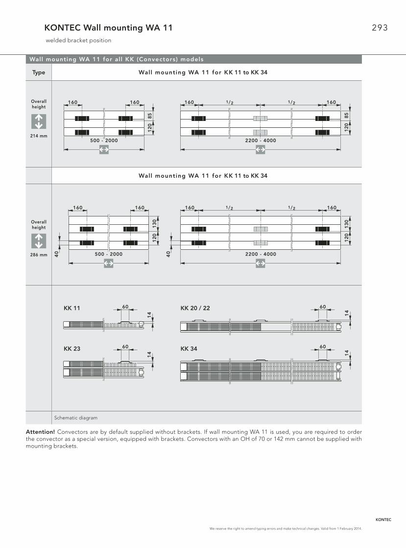
293
We reserve the right to amend typing errors and make technical changes. Valid from 1 February 2014.
KONTEC Wall mounting WA 11 welded bracket position
Wall mounting WA 11 for al l KK (Convectors) models
Type Wall mounting WA 11 for KK 11 to KK 34
Overallheight
214 mm
Wall mounting WA 11 for KK 11 to KK 34
Overallheight
286 mm
Schematic diagram
Attention! Convectors are by default supplied without brackets. If wall mounting WA 11 is used, you are required to order the convector as a special version, equipped with brackets. Convectors with an OH of 70 or 142 mm cannot be supplied with mounting brackets.
500 - 2000
160 160
85
12
0
160 1601/2 1/2
2200 - 4000
85
12
0
13
01
20
500 - 2000
160 160
40
13
01
20
160 160
2200 - 4000
1/2 1/2
40
60
14
60
14 14
601
4
60KK 11 KK 20 / 22
KK 23 KK 34
KONTEC
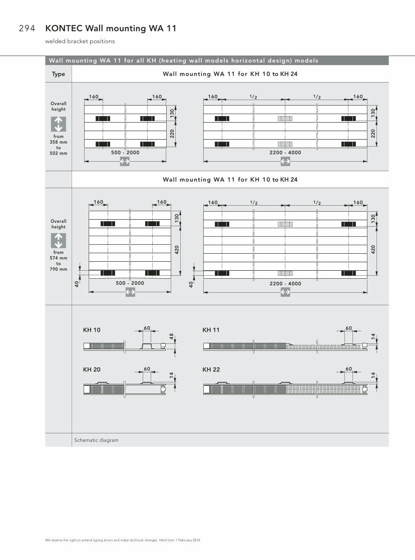
294
We reserve the right to amend typing errors and make technical changes. Valid from 1 February 2014.
KONTEC Wall mounting WA 11welded bracket positions
Wall mounting WA 11 for al l KH (heating wall models horizontal design) models
Type Wall mounting WA 11 for KH 10 to KH 24
Overallheight
from358 mm
to502 mm
Wall mounting WA 11 for KH 10 to KH 24
Overallheight
from574 mm
to790 mm
Schematic diagram
13
02
20
500 - 2000
160 160
13
02
20
160 160
2200 - 4000
1/2 1/2
13
04
20
500 - 2000
160 160
40
13
04
20
160 160
2200 - 400040
1/2 1/2
60
48
60
14
14
601
4
60KH 10 KH 11
KH 20 KH 22

295
We reserve the right to amend typing errors and make technical changes. Valid from 1 February 2014.
KONTEC Wall mounting WA 11Drilling and wall clearance dimensions
Wall mounting WA 11 for types KK (convectors) and KH (Vertical heating panels)
Wall mounting WA 11 is suitable for convector models KK (OH 214 and 286 mm, with brackets) and heating wall models KH (OH 358 - 790 mm). It ensures easy, rapid and robust mounting of KONTEC convectors or KONTEC heating panels still in the packaging.
Wall mounting WA 11 for OH 214 - 790
Wall mounting WA 11 dri l l ing dimensions
From an overal l length of 2200 mm: 3 consoles
Overall height [mm]Value X
[mm]Value Y
[mm]Value Z
[mm]Wall mounting WA 11
for OH 214 – 790 mm
214 104 162 52
286 131 189 97
358 203 261 97
430 275 333 97
502 347 405 97
574 419 477 97
646 491 549 97
790 635 693 97
Schematic diagram
Connection – wall c learance
Convector and heating panelmodels
Overal l height [mm]
MeasurementW [mm]
KK 11 214, 286 45
KK 20, KK 22, KK 34 214, 286 89
KK 23 214, 286 123,5
KH 10, KH 11 358 - 790 45
KH 20, KH 22 358 - 790 89
Schematic diagram
W
HeizkörperOberkante
HeizkörperUnterkante
XY
Z
KONTEC
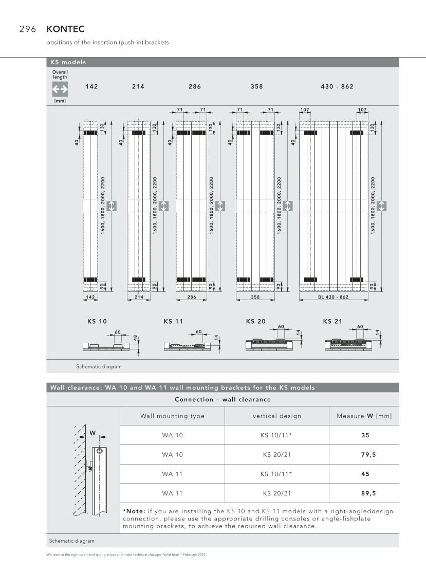
296
We reserve the right to amend typing errors and make technical changes. Valid from 1 February 2014.
KONTECpositions of the insertion (push-in) brackets
Overall length
[mm]
142 214 286 358 430 - 862
Schematic diagram
KS models
60
48
KS 10 KS 11 KS 20 KS 21
Wall c learance: WA 10 and WA 11 wall mounting brackets for the KS models
Connection – wall c learance
Wall mounting type vert ical design Measure W [mm]
WA 10 KS 10/11* 35
WA 10 KS 20/21 79,5
WA 11 KS 10/11* 45
WA 11 KS 20/21 89,5
*Note: i f you are instal l ing the KS 10 and KS 11 models with a r ight-angleddesignconnect ion, please use the appropriate dr i l l ing consoles or angle-f ishplatemounting brackets, to achieve the required wal l c learance.
Schematic diagram
W
60
14
KS 20 60
14
KS 21 60
14
142
16
00
, 1
80
0,
20
00
, 2
20
0130
90
40
214
16
00
, 1
80
0,
20
00
, 2
20
0130
90
40
286
16
00
, 1
80
0,
20
00
, 2
20
0130
7171
90
40
358
16
00
, 1
80
0,
20
00
, 2
20
0130
90
7171
40
BL 430 - 862
16
00
, 1
80
0,
20
00
, 2
20
0130
107107
90
40
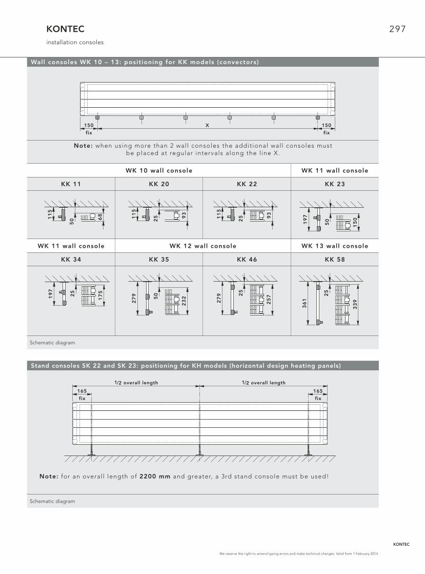
297
We reserve the right to amend typing errors and make technical changes. Valid from 1 February 2014.
KONTECinstallation consoles
Wall consoles WK 10 – 13: posit ioning for KK models (convectors)
Note: when using more than 2 wal l consoles the addit ional wal l consoles must be placed at regular intervals a long the l ine X.
WK 10 wall console WK 11 wall console
KK 11 KK 20 KK 22 KK 23
WK 11 wall console WK 12 wall console WK 13 wall console
KK 34 KK 35 KK 46 KK 58
Schematic diagram
150 150X
fix fix
68
501
15
2511
5
93
2511
5
93
25
17
5
19
7
50
23
2
27
9 25
25
7
27
9 25
33
9
36
1
Stand consoles SK 22 and SK 23: positioning for KH models (horizontal design heating panels)
Note: for an overal l length of 2200 mm and greater, a 3rd stand console must be used!
Schematic diagram
50
15
0
19
7
165 165
fix fix
Baulänge1/2 Baulänge1/21/2 overall length1/2 overall length
KONTEC

298
We reserve the right to amend typing errors and make technical changes. Valid from 1 February 2014.
KONTECMontagekonsolen
Stand consoles SK 10 - 19: positioning for KK / KK-S models
Window si l l support FBT 20: posit ioning for KK / KK-S models
Window si l l support for subsequent instal lat ion with the KK / KK-S 22 – 58 models of KONTEC convectors
Note: for an overal l length of more than 2200 mm , a 3rd window si l l support must be used!
Schematic diagram
Note: for an overal l length of 2200 mm and greater, a 3rd stand console must be used!
SK 10 / SK 11
KK 11
SK 12 / SK 13
KK 20
SK 12 / SK 13 SK 14 / SK 15
KK 22 KK 23 KK-S 22 KK 34 KK 35
SK 14 / SK 15 SK 16 / SK 17 SK 18 / SK 19
KK-S 34 KK 46 KK-S 47 KK 58
Measurement X:chosen distance between the wall or window surface and the back of the convector.
Schematic diagramX
65
68
33
X
88
,5
93
46
X
88
,5
93
46
88
,5
X
10
3
15
0
16
6,5
X1
637
7
16
6,5
X1
7589
16
6,5
X2
3214
6
16
6,5
X2
4515
9
24
5
X2
571
32
32
7
X3
271
61
32
7
X3
391
73
150 150
fix fix
Baulänge1/2 Baulänge1/2
constant constant
1/2 overall length1/2 overall length
150 150
fix fix
Baulänge1/2 Baulänge1/21/2 overall length1/2 overall length
constant constant
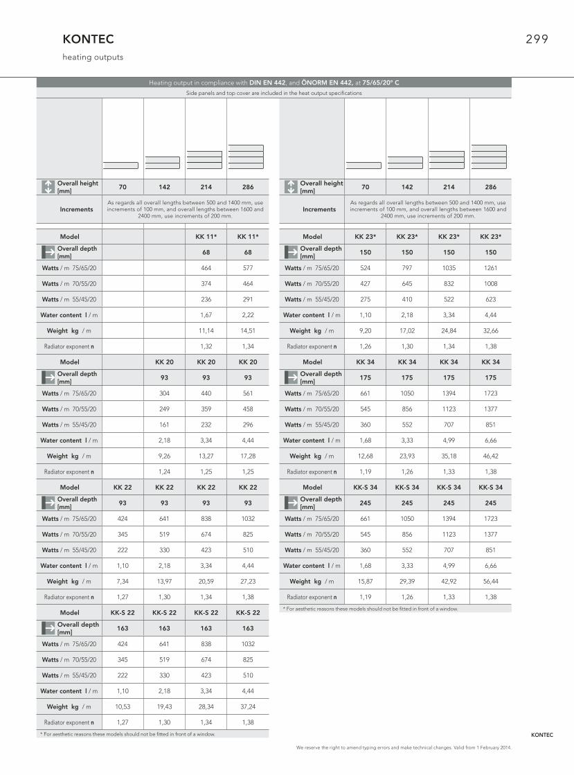
299
We reserve the right to amend typing errors and make technical changes. Valid from 1 February 2014.
KONTECheating outputs
Overall height [mm]
70 142 214 286
IncrementsAs regards all overall lengths between 500 and 1400 mm, use increments of 100 mm, and overall lengths between 1600 and
2400 mm, use increments of 200 mm.
Model KK 11* KK 11*
Overall depth [mm]
68 68
Watts / m 75/65/20 464 577
Watts / m 70/55/20 374 464
Watts / m 55/45/20 236 291
Water content l / m 1,67 2,22
Weight kg / m 11,14 14,51
Radiator exponent n 1,32 1,34
Model KK 20 KK 20 KK 20
Overall depth [mm]
93 93 93
Watts / m 75/65/20 304 440 561
Watts / m 70/55/20 249 359 458
Watts / m 55/45/20 161 232 296
Water content l / m 2,18 3,34 4,44
Weight kg / m 9,26 13,27 17,28
Radiator exponent n 1,24 1,25 1,25
Model KK 22 KK 22 KK 22 KK 22
Overall depth [mm]
93 93 93 93
Watts / m 75/65/20 424 641 838 1032
Watts / m 70/55/20 345 519 674 825
Watts / m 55/45/20 222 330 423 510
Water content l / m 1,10 2,18 3,34 4,44
Weight kg / m 7,34 13,97 20,59 27,23
Radiator exponent n 1,27 1,30 1,34 1,38
Model KK-S 22 KK-S 22 KK-S 22 KK-S 22
Overall depth [mm]
163 163 163 163
Watts / m 75/65/20 424 641 838 1032
Watts / m 70/55/20 345 519 674 825
Watts / m 55/45/20 222 330 423 510
Water content l / m 1,10 2,18 3,34 4,44
Weight kg / m 10,53 19,43 28,34 37,24
Radiator exponent n 1,27 1,30 1,34 1,38
* For aesthetic reasons these models should not be fi tted in front of a window.
Overall height [mm]
70 142 214 286
IncrementsAs regards all overall lengths between 500 and 1400 mm, use increments of 100 mm, and overall lengths between 1600 and
2400 mm, use increments of 200 mm.
Model KK 23* KK 23* KK 23* KK 23*
Overall depth [mm]
150 150 150 150
Watts / m 75/65/20 524 797 1035 1261
Watts / m 70/55/20 427 645 832 1008
Watts / m 55/45/20 275 410 522 623
Water content l / m 1,10 2,18 3,34 4,44
Weight kg / m 9,20 17,02 24,84 32,66
Radiator exponent n 1,26 1,30 1,34 1,38
Model KK 34 KK 34 KK 34 KK 34
Overall depth [mm]
175 175 175 175
Watts / m 75/65/20 661 1050 1394 1723
Watts / m 70/55/20 545 856 1123 1377
Watts / m 55/45/20 360 552 707 851
Water content l / m 1,68 3,33 4,99 6,66
Weight kg / m 12,68 23,93 35,18 46,42
Radiator exponent n 1,19 1,26 1,33 1,38
Model KK-S 34 KK-S 34 KK-S 34 KK-S 34
Overall depth [mm]
245 245 245 245
Watts / m 75/65/20 661 1050 1394 1723
Watts / m 70/55/20 545 856 1123 1377
Watts / m 55/45/20 360 552 707 851
Water content l / m 1,68 3,33 4,99 6,66
Weight kg / m 15,87 29,39 42,92 56,44
Radiator exponent n 1,19 1,26 1,33 1,38
* For aesthetic reasons these models should not be fi tted in front of a window.
Heating output in compliance with DIN EN 442, and ÖNORM EN 442, at 75/65/20° C
Side panels and top cover are included in the heat output specifi cations
KONTEC
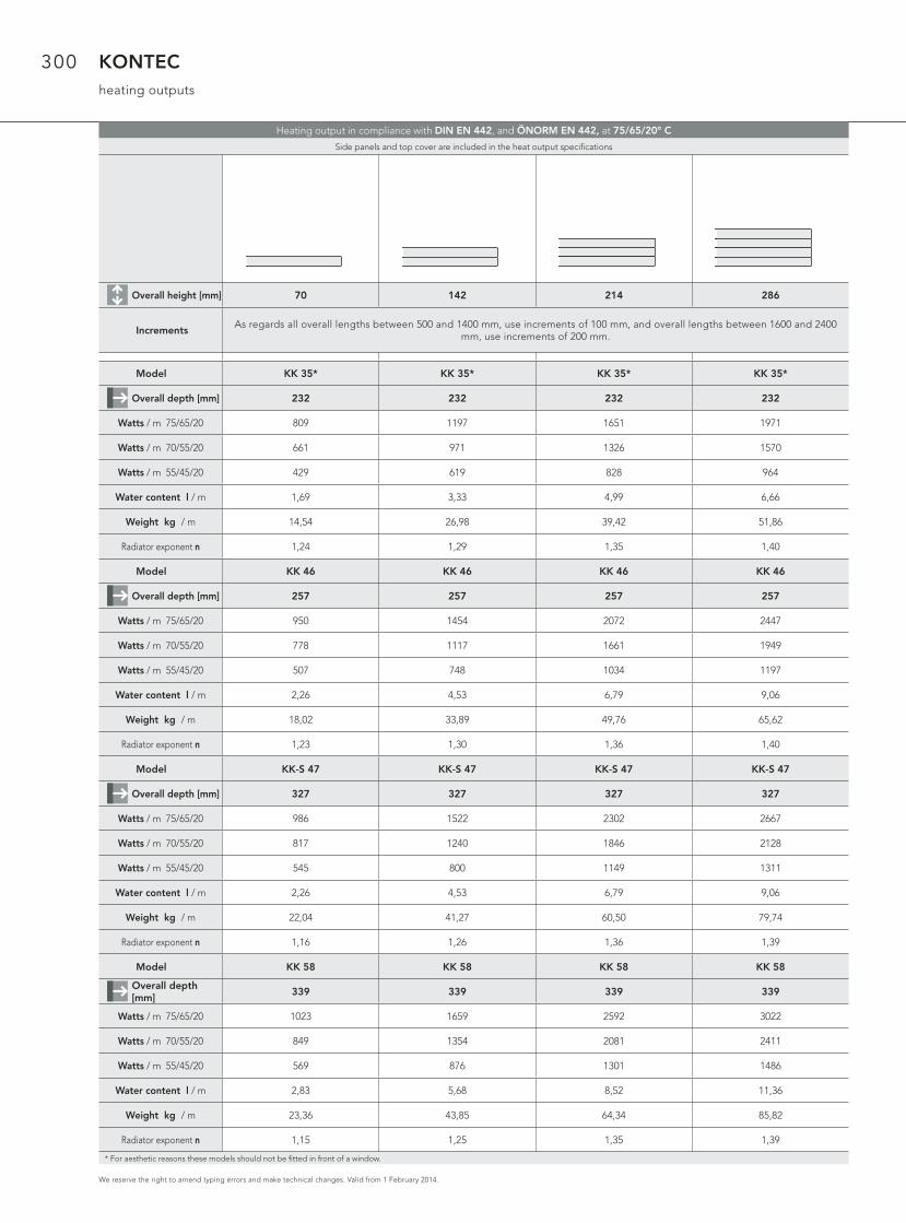
300
We reserve the right to amend typing errors and make technical changes. Valid from 1 February 2014.
KONTECheating outputs
Overall height [mm] 70 142 214 286
IncrementsAs regards all overall lengths between 500 and 1400 mm, use increments of 100 mm, and overall lengths between 1600 and 2400
mm, use increments of 200 mm.
Model KK 35* KK 35* KK 35* KK 35*
Overall depth [mm] 232 232 232 232
Watts / m 75/65/20 809 1197 1651 1971
Watts / m 70/55/20 661 971 1326 1570
Watts / m 55/45/20 429 619 828 964
Water content l / m 1,69 3,33 4,99 6,66
Weight kg / m 14,54 26,98 39,42 51,86
Radiator exponent n 1,24 1,29 1,35 1,40
Model KK 46 KK 46 KK 46 KK 46
Overall depth [mm] 257 257 257 257
Watts / m 75/65/20 950 1454 2072 2447
Watts / m 70/55/20 778 1117 1661 1949
Watts / m 55/45/20 507 748 1034 1197
Water content l / m 2,26 4,53 6,79 9,06
Weight kg / m 18,02 33,89 49,76 65,62
Radiator exponent n 1,23 1,30 1,36 1,40
Model KK-S 47 KK-S 47 KK-S 47 KK-S 47
Overall depth [mm] 327 327 327 327
Watts / m 75/65/20 986 1522 2302 2667
Watts / m 70/55/20 817 1240 1846 2128
Watts / m 55/45/20 545 800 1149 1311
Water content l / m 2,26 4,53 6,79 9,06
Weight kg / m 22,04 41,27 60,50 79,74
Radiator exponent n 1,16 1,26 1,36 1,39
Model KK 58 KK 58 KK 58 KK 58
Overall depth [mm]
339 339 339 339
Watts / m 75/65/20 1023 1659 2592 3022
Watts / m 70/55/20 849 1354 2081 2411
Watts / m 55/45/20 569 876 1301 1486
Water content l / m 2,83 5,68 8,52 11,36
Weight kg / m 23,36 43,85 64,34 85,82
Radiator exponent n 1,15 1,25 1,35 1,39
* For aesthetic reasons these models should not be fi tted in front of a window.
Heating output in compliance with DIN EN 442, and ÖNORM EN 442, at 75/65/20° C
Side panels and top cover are included in the heat output specifi cations

301
We reserve the right to amend typing errors and make technical changes. Valid from 1 February 2014.
KONTECheating outputs
Heating output in compliance with DIN EN 442, and ÖNORM EN 442, at 75/65/20° C
Side panels and top cover are included in the heat output specifi cations
Overall height [mm] 358 430 502 574 646 790
IncrementsAs regards all overall lengths between 500 and 1400 mm, use increments of 100 mm, and overall lengths between 1600 and 2400
mm, use increments of 200 mm.
Model KH 10 KH 10 KH 10 KH 10 KH 10 KH 10
Overall depth [mm] 68 68 68 68 68 68
Watts / m 75/65/20 394 458 523 588 655 795
Watts / m 70/55/20 322 374 427 480 534 647
Watts / m 55/45/20 209 243 276 311 344 416
Water content l / m 2,76 3,33 3,87 4,44 4,99 6,12
Weight kg / m 11,91 14,04 16,17 18,29 20,43 24,68
Radiator exponent n 1,24 1,24 1,25 1,25 1,26 1,27
Model KH 11* KH 11* KH 11* KH 11* KH 11* KH 11*
Overall depth [mm] 68 68 68 68 68 68
Watts / m 75/65/20 667 760 845 921 989 1105
Watts / m 70/55/20 540 615 683 743 797 889
Watts / m 55/45/20 344 391 433 470 503 558
Water content l / m 2,78 3,33 3,87 4,44 4,99 6,12
Weight kg / m 16,71 19,85 22,99 26,15 29,29 33,55
Radiator exponent n 1,30 1,30 1,31 1,32 1,32 1,34
Model KH 20 KH 20 KH 20 KH 20 KH 20 KH 20
Overall depth [mm] 93 93 93 93 93 93
Watts / m 75/65/20 654 757 859 960 1063 1271
Watts / m 70/55/20 533 617 699 781 863 1032
Watts / m 55/45/20 344 398 449 502 553 661
Water content l / m 5,55 6,66 7,77 8,88 9,99 12,22
Weight kg / m 21,29 25,30 29,31 33,31 37,32 45,33
Radiator exponent n 1,26 1,26 1,27 1,27 1,28 1,28
Model KH 22 KH 22 KH 22 KH 22 KH 22 KH 22
Overall depth [mm] 93 93 93 93 93 93
Watts / m 75/65/20 1197 1343 1474 1592 1699 1886
Watts / m 70/55/20 963 1079 1182 1274 1357 1500
Watts / m 55/45/20 605 675 736 790 838 919
Water content l / m 5,55 6,66 7,77 8,88 9,99 12,22
Weight kg / m 30,89 36,93 42,96 49,01 55,05 63,06
Radiator exponent n 1,34 1,35 1,36 1,37 1,38 1,41
* For aesthetic reasons these models should not be fi tted in front of a window. KONTEC
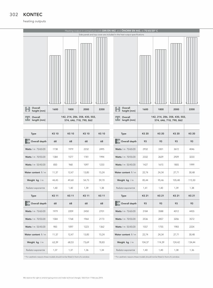
302
We reserve the right to amend typing errors and make technical changes. Valid from 1 February 2014.
KONTECheating outputs
Overall height [mm]
1600 1800 2000 2200
Overall length [mm]
142, 214, 286, 358, 430, 502, 574, 646, 718, 790, 862
Type KS 10 KS 10 KS 10 KS 10
Overall depth 68 68 68 68
Watts / m 75/65/20 1738 1979 2232 2495
Watts / m 70/55/20 1384 1577 1781 1994
Watts / m 55/45/20 850 968 1097 1233
Water content l / m 11,37 12,47 13,85 15,24
Weight kg / m 44,45 49,60 54,75 59,70
Radiator exponent n 1,40 1,40 1,39 1,38
Type KS 11 KS 11 KS 11 KS 11
Overall depth 68 68 68 68
Watts / m 75/65/20 1979 2209 2450 2701
Watts / m 70/55/20 1584 1768 1964 2173
Watts / m 55/45/20 983 1097 1223 1362
Water content l / m 11,37 12,47 13,85 15,24
Weight kg / m 63,39 68,53 73,69 78,83
Radiator exponent n 1,37 1,37 1,36 1,34
* For aesthetic reasons these models should not be fi tted in front of a window.
Overall height [mm]
1600 1800 2000 2200
Overall length [mm]
142, 214, 286, 358, 430, 502, 574, 646, 718, 790, 862
Type KS 20 KS 20 KS 20 KS 20
Overall depth 93 93 93 93
Watts / m 75/65/20 2932 3301 3672 4046
Watts / m 70/55/20 2332 2629 2929 3233
Watts / m 55/45/20 1427 1615 1805 1999
Water content l / m 22,74 24,34 27,71 30,48
Weight kg / m 85,44 95,46 105,48 115,50
Radiator exponent n 1,41 1,40 1,39 1,38
Type KS 21 KS 21 KS 21 KS 21
Overall depth 93 93 93 93
Watts / m 75/65/20 3184 3588 4012 4455
Watts / m 70/55/20 2536 2857 3206 3572
Watts / m 55/45/20 1557 1755 1983 2224
Water content l / m 22,74 24,34 27,71 30,48
Weight kg / m 104,37 114,39 124,42 134,44
Radiator exponent n 1,40 1,40 1,38 1,36
* For aesthetic reasons these models should not be fi tted in front of a window.
Heating output in compliance with DIN EN 442, and ÖNORM EN 442, at 75/65/20° C
Side panels and top cover are included in the heat output specifi cations

303
We reserve the right to amend typing errors and make technical changes. Valid from 1 February 2014.
KONTEC Replacement radiatorproduct description
Convectors & heating panels are ra-diators in a completely welded design, with 2 or 3 water-bearing rectangu-lar steel pipes arranged behind each other and 4 or 8 on top of each other. Between the heating pipes there is a gap of 2 mm in order to ensure high resistance to corrosion. Each convec-tor or heating wall is equipped with side panels and a top cover. They are also supplied with a drain plug and a pivotable vent plug, all of the factory sealed.
Painting:1. Primer coat with electro-dip coating using water-soluble paint, in acc. with DIN 55900, part 1, stoved at 165 °C.2. Electrostatic fi nish in acc. with DIN 55900, part 2, in RAL 9016 (on reque-st in many RAL and Sanitary Ware co-lours), in a state-of-the-art powder coating plant.The especially robust coating is stoved at an object tempe-rature of 180 °C.
Standard design:Rectangular steel pipes: 70 x 11 x 1.5 mmHigh-pressure version:Rectangular steel pipes: 70 x 11 x 2 mmPlease note: surcharge of 10%
Packaging:1. Cardboard2. Edge protection3. Shrink foil
Connections:2 x 1/2“internal thread, welded on, for fl ow and return, venting and drainage, according to the customer’s specifi cations.
Maximum positive operating pressure:Standard design: 5 barMaximum positive operating pressure:High-pressure design: 8 bar
Maximum operating temperature:110 °C
5 barmax.
8 barmax.
max
.
REPLACEMENTUSING CONVECTORS & HEATING PANELS
Guarantee statements are available to download at www.vogelundnoot.com/download
Convectors & Heating panels
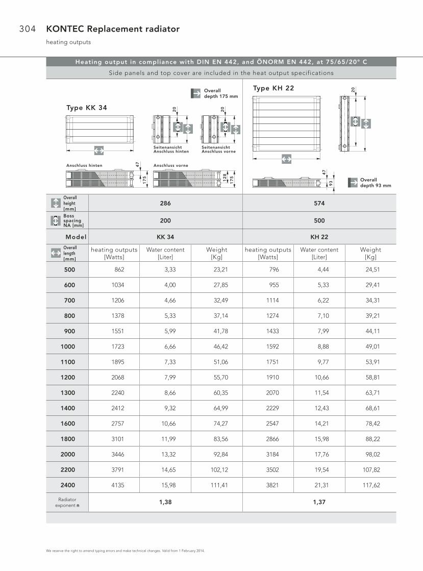
304
We reserve the right to amend typing errors and make technical changes. Valid from 1 February 2014.
KONTEC Replacement radiatorheating outputs
Heating output in compliance with DIN EN 442, and ÖNORM EN 442, at 75/65/20° C
Side panels and top cover are included in the heat output specifications
Overall height [mm]
286 574
Boss spacing NA [mm]
200 500
Model KK 34 KH 22
Overall length [mm]
heating outputs[Watts]
Water content [Liter]
Weight[Kg]
heating outputs[Watts]
Water content [Liter]
Weight[Kg]
500
600
700
800
900
1000
1100
1200
1300
1400
1600
1800
2000
2200
2400
Radiator exponent n
862
1034
1206
1378
1551
1723
1895
2068
2240
2412
2757
3101
3446
3791
4135
796
955
1114
1274
1433
1592
1751
1910
2070
2229
2547
2866
3184
3502
3821
1,38 1,37
3,33
4,00
4,66
5,33
5,99
6,66
7,33
7,99
8,66
9,32
10,66
11,99
13,32
14,65
15,98
23,21
27,85
32,49
37,14
41,78
46,42
51,06
55,70
60,35
64,99
74,27
83,56
92,84
102,12
111,41
4,44
5,33
6,22
7,10
7,99
8,88
9,77
10,66
11,54
12,43
14,21
15,98
17,76
19,54
21,31
24,51
29,41
34,31
39,21
44,11
49,01
53,91
58,81
63,71
68,61
78,42
88,22
98,02
107,82
117,62
20
SeitenansichtAnschluss vorne
20
SeitenansichtAnschluss hinten
Type KK 34
Anschluss hinten
17
5
47
Anschluss vorne
17
5
12
8
20Type KH 22
93
47
Overalldepth 175 mm
Overalldepth 93 mm
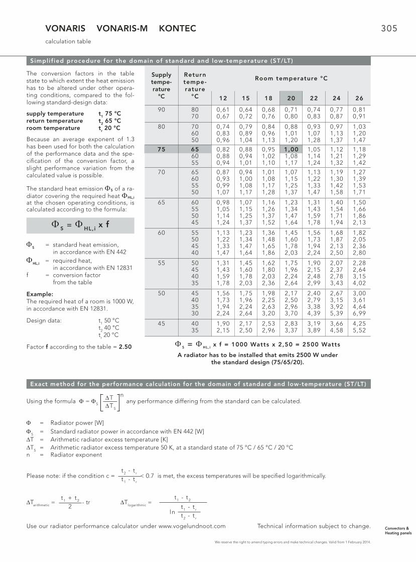
305
We reserve the right to amend typing errors and make technical changes. Valid from 1 February 2014.
VONARIS VONARIS-M KONTECcalculation table
Simplif ied procedure for the domain of standard and low-temperature (ST/LT)
The conversion factors in the table state to which extent the heat emission has to be altered under other opera-ting conditions, compared to the fol-lowing standard-design data:
supply temperature t1 75 °Creturn temperature t2 65 °Croom temperature tr 20 °C
Because an average exponent of 1.3 has been used for both the calculation of the performance data and the spe-cifi cation of the conversion factor, a slight performance variation from the calculated value is possible.
The standard heat emission ΦS of a ra-diator covering the required heat ΦHL,i at the chosen operating conditions, is calculated according to the formula:
ΦS = standard heat emission, in accordance with EN 442ΦHL,i = required heat, in accordance with EN 12831f = conversion factor from the table
Example:The required heat of a room is 1000 W,in accordance with EN 12831.
Design data: t1 50 °C t2 40 °C tr 20 °C
Factor f according to the table = 2.50
Φ S = ΦHL,i x f
Exact method for the performance calculation for the domain of standard and low-temperature (ST/LT)
Supplytempe-rature
°C
Returntempe-rature
°C
Room temperature °C
12 15 18 20 22 24 26
90 8070
0,610,67
0,640,72
0,680,76
0,710,80
0,740,83
0,770,87
0,810,91
80 706050
0,740,830,96
0,790,891,04
0,840,961,13
0,881,011,20
0,931,071,28
0,971,131,37
1,031,201,47
75 656055
0,820,880,94
0,880,941,01
0,951,021,10
1,001,081,17
1,051,141,24
1,121,211,32
1,181,291,42
70 65605550
0,870,930,991,07
0,941,001,081,17
1,011,081,171,28
1,071,151,251,37
1,131,221,331,47
1,191,301,421,58
1,271,391,531,71
65 60555045
0,981,051,141,24
1,071,151,251,37
1,161,261,371,52
1,231,341,471,64
1,311,431,591,78
1,401,541,711,94
1,501,661,862,13
60 55504540
1,131,221,331,47
1,231,341,471,64
1,361,481,651,86
1,451,601,782,03
1,561,731,942,24
1,681,872,132,50
1,822,052,362,80
55 50454035
1,311,431,591,78
1,451,601,782,03
1,621,802,032,36
1,751,962,242,64
1,902,152,482,99
2,072,372,783,43
2,282,643,154,02
50 45403530
1,561,731,942,24
1,751,962,242,64
1,982,252,633,20
2,172,502,963,70
2,402,793,384,39
2,673,153,925,39
3,003,614,646,99
45 4035
1,902,15
2,172,50
2,532,96
2,833,37
3,193,89
3,664,58
4,255,52
Φ S = Φ HL,i x f = 1000 Watts x 2,50 = 2500 Watts
A radiator has to be installed that emits 2500 W under the standard design (75/65/20).
75 65
Using the formula Φ = ΦS any performance differing from the standard can be calculated.
Φ = Radiator power [W] ΦS = Standard radiator power in accordance with EN 442 [W]ΔT = Arithmetic radiator excess temperature [K]ΔTS = Arithmetic radiator excess temperature 50 K, at a standard state of 75 °C / 65 °C / 20 °Cn = Radiator exponent
Please note: if the condition c = < 0.7 is met, the excess temperatures will be specifi ed logarithmically.
ΔTarithmetic = - tr ΔTlogarithmic =
Use our radiator performance calculator under www.vogelundnoot.com Technical information subject to change.
ΔTΔTS
n
t 2 - t r
t 1 - t r
t 1 + t 2
2
t 1 - t 2
ln t 1 - t r
t 2 - t r
Convectors & Heating panels

306
We reserve the right to amend typing errors and make technical changes. Valid from 1 February 2014.
VONARIS VONARIS-M KONTECinstallation dimensions
Horizontal design of VONARIS, VONARIS-M and KONTEC
Radiator placement
Placementbelow a window parapet
X + Y = GC Placementunder a bench
Thermal insulation
Placementbehind a glass surface
X + Y = GC Placementbelow a shop window
B = GC
Schematic diagram
X
Y
BA15
X + Y = BA Wärmedämmung
BA
BA 2
X
YB
A
15
X + Y = BA
B
BA
15
B = BA
5
Recommended minimum clearance for convectors
VONARIS VONARIS-M KONTEC
GC [mm] ModelOH
[mm]Model
OH[mm]
ModelOH
[mm]
GC = ground clearance in mm
The minimum ground clearance recommended hereapply for all images on the pages 306 and 307!
60 VHV 11 214, 286 VHV-M 11 214, 286 KK 11 214, 286
60 VHV 20 142 VHV-M 20 142 KK 20 142
60 VHV 22 142 VHV-M 22 142 KK 22 70, 142
70 VHV 23 142 VHV-M 23 142 KK 23 70, 142
80 VHV 20 214, 286 VHV-M 20 214, 286 KK 20 214, 286
80 VHV 22 214, 286 VHV-M 22 214, 286 KK 22 214, 286
90 VHV 23 214, 286 VHV-M 23 214, 286 KK 23 214, 286
100 VHV 34 142 VHV-M 34 142 KK 34 70, 142
110 VHV 34 214, 286 VHV-M 34 214, 286 KK 34 214, 286
120 VHV 35 142 VHV-M 35 142 KK 35 70, 142
130 VHV 35 214, 286 VHV-M 35 214, 286 KK 35 214, 286
130 VHV 46 142 VHV-M 46 142 KK 46 70, 142
130 - - - - KK 58 70
140 - - - - KK 46 214, 286
140 - - - - KK 58 142
150 - - - - KK 58 214, 286
GC
GC
GC
GC
GC

307
We reserve the right to amend typing errors and make technical changes. Valid from 1 February 2014.
VONARIS VONARIS-M KONTECinstallation dimensions
Horizontal design of VONARIS, VONARIS-M and KONTEC
Radiator placement
Placementbehind ascreen
Placementbehind adesk
Schematische Darstellung
BA
5
15
hB
A
Bild 1
15
Bild 2
BA
h
5
BA Isolation
Note: Screens and desks should be movable so that the radiators and conduits can be cleaned.
Percentage increase of the radiator’s heat emission due to the chimney effect, as Illustrated with the placement in picture 1 and picture 2.
h [mm]
Percentage increase of the heat emission
OH 70 mm OH 142 mm OH 214 mm OH 286 mm
150 14 - - -
200 20 8 - -
250 26 12 2 -
300 30 15 6 -
350 33 19 9 3
400 36 22 12 6
450 39 25 15 9
500 41 28 17 11
600 46 32 21 14
700 50 35 24 18
800 - 38 27 21
GC GC Insulation
Image 2Image 1
GC
GC
Convectors & Heating panels

308
We reserve the right to amend typing errors and make technical changes. Valid from 1 February 2014.
VONARIS VONARIS-M KONTECinstallation dimensions
Horizontal design of VONARIS, VONARIS-M and KONTEC
Placement of the radiators in regard to f loor conduits
Schematic diagram
Abdeckg itter
55
C
C C
B
B = Bautiefe Heizkörper + 10 mmC BIV
Abdeckg itter
15
5
C
C
B
B = Bautiefe Heizkörper + 20 mmC BIV
The screening between the radiator surfaces and conduit walls must be made of heat-insulating materials (e. g.: timber, pla-stics etc.).
Take care that the lower edge of the screening corresponds to the lower edge of the radiator. The top edge of the screening should be fi tted as near to the fl oor conduit cover as possible.
The cover grids of the fl oor conduit should be designed in a way that the open cross-sectional area amounts to at least 60 %.
We recommend to use cover grids that can easily be taken off in order to facilitate the cleaning of the fl oor conduit.
The heat emission of radiators installed in fl oor conduits (subsurface heating) is reduced at about 20 %, compared with the values given in the heat output index.
B = Overall radiator depth + 10 mmC ≥ B
B = Overall radiator depth + 20 mmC ≥ B
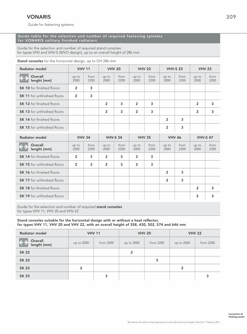
309
We reserve the right to amend typing errors and make technical changes. Valid from 1 February 2014.
VONARIS Guide for fastening systems
Guide table for the selection and number of required fastening systems for VONARIS sol itary f inished radiators
Guide for the selection and number of required stand consolesfor types VHV and VHV-S (WVO design), up to an overall height of 286 mm
Stand consoles for the horizontal design, up to OH 286 mm
Radiator model VHV 11 VHV 20 VHV 22 VHV-S 22 VHV 23
Overall lenght [mm]
up to 2000
from 2200
up to 2000
from 2200
up to 2000
from 2200
up to 2000
from 2200
up to 2000
from 2200
SK 10 for fi nished fl oors 2 3
SK 11 for unfi nished fl oors 2 3
SK 12 for fi nished fl oors 2 3 2 3 2 3
SK 13 for unfi nished fl oors 2 3 2 3 2 3
SK 14 for fi nished fl oors 2 3
SK 15 for unfi nished fl oors 2 3
Radiator model VHV 34 VHV-S 34 VHV 35 VHV 46 VHV-S 47
Overall lenght [mm]
up to 2000
from 2200
up to 2000
from 2200
up to 2000
from 2200
up to2000
from 2200
up to 2000
from 2200
SK 14 for fi nished fl oors 2 3 2 3 2 3
SK 15 for unfi nished fl oors 2 3 2 3 2 3
SK 16 for fi nished fl oors 2 3
SK 17 for unfi nished fl oors 2 3
SK 18 for fi nished fl oors 2 3
SK 19 for unfi nished fl oors 2 3
Guide for the selection and number of required stand consolesfor types VHV 11, VHV 20 and VHV 22
Stand consoles suitable for the horizontal design with or without a heat refl ector,for types VHV 11, VHV 20 and VHV 22, with an overall height of 358, 430, 502, 574 and 646 mm
Radiator model VHV 11 VHV 20 VHV 22
Overall lenght [mm]
up to 2000 from 2200 up to 2000 from 2200 up to 2000 from 2200
SK 22 2
SK 22 3
SK 23 2 2
SK 23 3 3
Convectors & Heating panels

310
We reserve the right to amend typing errors and make technical changes. Valid from 1 February 2014.
VONARISGuide for fastening systems
Guide table for the selection and number of required fastening systems for VONARIS sol itary f inished radiators
Guide for the selection and number of required wall consolesfor types VHV, up to an overall height of 286 mm
Wall consoles for the horizontal design, up to OH 286 mm
Radiator model VHV 34 VHV 35 VHV 35 VHV 35
Wall console model WK 11-M WK 12 WK 12 WK 12
Overall length [mm]
between 500and 2000
between 2200 and 4000
between 500 and 2000
between 2200 and 4000
between 500 and 1800
between 2000 and 2600
between 2800 and 3600
between 3800 and 4000
Overall height
[mm]
142 2 3 2 3
214 2 3 2 3
286 2 3 2 3 4 5
Radiator model VHV 11 VHV 20 VHV 22 VHV 23
Wall console model WK 10 WK 10 - M WK 10 - M WK 11-M
Overall length [mm]
between 500 and 2000
between 2200 and 4000
between 500 and 2000
between 2200 and 4000
between 500 and 2000
between 2200 and 4000
between 500 and 2000
between 2200 and 4000
Overall height
[mm]
142 2 3 2 3 2 3
214 2 3 2 3 2 3 2 3
286 2 3 2 3 2 3 2 3
Radiator model VHV 46 VHV 46 VHV 46 VHV 46
Wall console model WK 12 WK 12 WK 12 WK 12
Overall length [mm]
between 500 and 2000
between 2200 and 3000
between 500 and 1800
between 2000 and 2800
3000between 500
and 1400between 1600
and 2200between 2400
and 2800
Overall height
[mm]
142 2 3
214 2 3 4
286 5 2 3 4
Guide table for the selection and number of required fastening systems for VONARIS sol itary f inished radiators
Guide for the selection and number of required VONOFIX rapid installation consolesfor types VHV 20, VHV 22 and VHV 34
VONOFIX rapid installation consoles for overall heights of 214, 286, 358, 430, 502, 574, 646 and 790 mm
Radiator model VHV 20 VHV 22 VHV 34
Overall length [mm] up to 2000 from 2200with foot console
up to 2000 from 2200with foot console
up to 2000 from 2200with foot console
Overallheight
[mm]
VONOFIX 1 (set for 214) 1 1 1 1 1 1
VONOFIX 2 (set for 286) 1 1 1 1 1 1
VONOFIX 2 (set for 358) 1 1 1 1
VONOFIX 3 (set for 430) 1 1 1 1
VONOFIX 3 (set for 502) 1 1 1 1
VONOFIX 4 (set for 574) 1 1 1 1
VONOFIX 4 (set for 646) 1 1 1 1
VONOFIX 5 (set for 790) 1 1 1 1

311
We reserve the right to amend typing errors and make technical changes. Valid from 1 February 2014.
VONARIS & VONARIS-MGuide for fastening systems
Radiator model VHV-M 22 VHV-M 34 VHV-M 46
Wall console model WK 10 - M WK 11 - M WK 12
Overall length [mm]
between 500 and 2000
between 2200 and 2400
between 500 and 2000
between 2000 and 2400
between 500 and 2000
between 2200 and 2400
Overall height
[mm]
142 2 3
214 2 3 4
286 5 2
Guide table for the selection and number of required fastening systems for VONARIS sol itary f inished radiators
Radiator model VSV 10 VSV 11 VSV 20 VSV 21
Overall length [mm] 214 ab 286 214 ab 286 214 ab 286 214 ab 286
WA 10, set 1 1 1 1
WA 11, set of 2 1 1 1 1
Guide for the selection and number of required VONOFIX rapid installation consolesfor types VSV 10, VSV 11, VSV 20 and VSV 21
Wall mounting brackets for the vertical design
Guide table for the selection and number of required fastening systems for VONARIS central connection radiators
Guide for the selection and number of required stand consolesfor types VHV-M up to an overall height of 286 mm.
Stand consoles for the horizontal design, up to OH 286 mm
Radiator model VHV-M 22 VHV-M S 22 VHV-M 34 VHV-M 46 VHV-M S 46
Overall length [mm]
up to 2000
from2200
up to 2000
from 2200
up to 2000
from 2200
up to 2000
from 2200
up to 2000
from 2200
SK 12 for fi nished fl oors 2 3
SK 13 for unfi nished fl oors 2 3
SK 14 for fi nished fl oors 2 3 2 3
SK 15 for unfi nished fl oors 2 3 2 3
SK 16 for fi nished fl oors 2 3
SK 17 for unfi nished fl oors 2 3
SK 18 for fi nished fl oors 2 3
SK 19 for unfi nished fl oors 2 3
Guide table for the selection and number of required fastening systems for VONARIS central connection radiators
Guide for the selection and number of required wall fastening bracketsfor types VSV-M 10, VSV-M 11, VSV-M 20 and VSV-M 21
Wall fastening brackets for the vertical design
Convectors & Heating panels

312
We reserve the right to amend typing errors and make technical changes. Valid from 1 February 2014.
VONARIS-M & KONTECGuide for fastening systems
Guide table for the selection and number of required fastening systems for VONARIS central connection radiators
Guide for the selection and number of required VONOFIX rapid installation consolesfor types VHV-M 20, VHV-M 22 and VHV-M 34
VONOFIX rapid installation consoles for overall heights of 214, 286, 358, 430, 502, 574, 646 and 790 mm
Radiator model VHV-M 20 VHV-M 22 VHV-M 34
Overall length [mm] up to 2000 from 2200with foot console
up to 2000 from 2200with foot console
up to 2000 from 2200with foot console
Overallheight
[mm]
VONOFIX 1 (set for 214) 1 1 1 1
VONOFIX 2 (set for 286) 1 1 1 1
VONOFIX 2 (set for 358) 1 1 1 1
VONOFIX 3 (set for 430) 1 1 1 1
VONOFIX 3 (set for 502) 1 1 1 1
VONOFIX 4 (set for 574) 1 1 1 1
VONOFIX 4 (set for 646) 1 1 1 1
VONOFIX 5 (set for 718) 1 1 1 1
VONOFIX 5 (set for 790) 1 1 1 1
Radiator model VSV-M 10* VSV-M 11* VSV-M 20 VSV-M 21
Overall length [mm] 214 ab 286 214 ab 286 214 ab 286 214 ab 286
WA 10, set 1 1 1 1
WA 11, set of 2 1 1 1 1
Guide for the selection and number of required wall fastening bracketsfor types VSV-M 10, VSV-M 11, VSV-M 20 and VSV-M 21
Wall fastening brackets for the vertical design
*Note: when installing the VSV-M 10 and VSV-M 11 models with an angled connection set (ZE, EE), please use the appropriate drill consoles and angled fi shplates to ensure that the required distance from the wall is maintained.
Guide table for the selection and number of required fastening systems for KONTEC convectors
Guide for the selection and number of required stand consolesfor KONTEC convectors, types KK and KK-S (WVO design)
Stand consoles for convectors without brackets
Radiator model KK 11 KK 20 KK 22 KK-S 22
Overall length [mm]
up to 2000 from 2200 up to 2000 from 2200 up to 2000 from 2200 up to 2000 from 2200
SK 10 for fi nisched fl oors 2 3
SK 11 for unfi nished fl oors 2 3
SK 12 for fi nisched fl oors 2 3 2 3
SK 13 for unfi nished fl oors 2 3 2 3
SK 14 for fi nisched fl oors 2 3
SK 15 for unfi nished fl oors 2 3

313
We reserve the right to amend typing errors and make technical changes. Valid from 1 February 2014.
KONTECGuide for fastening systems
Guide table for the selection and number of required fastening systems for KONTEC convectors
Guide for the selection and number of required stand consolesfor KONTEC convectors, types KK and KK-S (WVO design)
Stand consoles for convectors without brackets
Radiator model KK 23 KK 34 KK-S 34 KK 35
Overall length [mm] up to 2000 from 2200 up to 2000 from 2200 up to 2000 from 2200 up to 2000 from 2200
SK 12 for fi nished fl oors 2 3
SK 13 for unfi nished fl oors 2 3
SK 14 for fi nished fl oors 2 3 2 3 2 3
SK 15 for unfi nished fl oors 2 3 2 3 2 3
Radiator model KK 46 KK-S 47 KK 58
Overall length [mm] up to 2000 from 2200 up to 2000 from 2200 up to 2000 from 2200
SK 16 for fi nished fl oors 2 3
SK 17 for unfi nished fl oors 2 3
SK 18 for fi nished fl oors 2 3 2 3
SK 19 for unfi nished fl oors 2 3 2 3
Guide for the selection and number of required wall consolesfor KONTEC convectors, type KK
Wall consoles for convectors without brackets
Guide table for the selection and number of required fastening systems for KONTEC convectors
Radiator model KK 11 KK 20 KK 22 KK 23 KK 34
Wall console model WK 10 WK 10 - M WK 10 - M WK 11-M WK 11-M
Overall length [mm]
between 500 and
2000
between 2200 and
4000
between 500 and
2000
between 2200 and
4000
between 500 and
2000
between 2200 and
4000
between 500 and
2000
between 2200 and
4000
between 500 and
2000
between 2200 and
4000
Overall height
[mm]
70 2 3 2 3 2 3 2 3
142 2 3 2 3 2 3 2 3
214 2 3 2 3 2 3 2 3 2 3
286 2 3 2 3 2 3 2 3 2 3
Radiator model KK 35 KK 35 KK 35 KK 46 KK 46
Wall console model WK 12 WK 12 WK 12 WK 12 WK 12
Overall length [mm]
between 500 and
2000
between 2200 and
4000
between 500 and
1800
between 2000 and
2600
between 2800 and
3600
between 3800 and
4000
between 500 and
2000
between 2200 and
3000
between 500 and
1900
between 2000 and
2800
Overall height
[mm]
70 2 3 2 3
142 2 3 2 3
214 2 3 2 3
286 2 3 4 5
Convectors & Heating panels

314
We reserve the right to amend typing errors and make technical changes. Valid from 1 February 2014.
KONTECGuide for fastening systems
Guide table for the selection and number of required fastening systems for KONTEC convectors
Guide table for the selection and number of required fastening systems for KONTEC convectors
Guide for the selection and number of required fastening systems for KONTEC heating panels
Stand consoles, suitable for horizontal heating panels with or without heat refl ector,for types KH 11, KH 20 and KH 22
Radiator model KH 11 KH 20 KH 22
Overall length [mm]
up to 2000 from 2200 up to 2000 from 2200 up to 2000 from 2200
SK 22 2
SK 22 3
SK 23 2 2
SK 23 3 3
Radiator model KS 10 KS 11 KS 20 KS 21
Overall length [mm] up to 214 from 286 up to 214 from 286 up to 214 from 286 up to 214 from 286
WA 10, set 1 1 1 1
WA 11, set of 2 1 1 1 1
Guide for the selection and number of required wall fastening bracketsfor vertical KONTEC heating panels, type KS
Wall fastening brackets for vertical heating panels
Guide for the selection and number of required wall consolesfor KONTEC convectors, type KK
Wall consoles for convectors without brackets
Radiator model KK 46 KK 46 KK 58 KK 58 KK 58
Wall console model WK 12 WK 12 WK 13 WK 13 WK 13
Overall length [mm]
3000between 500 and
1400
between 1500 and
2200
between 2400 and
2800
between 500 and
20002200
between 500 and
1700
between 1800 and
2200
between 500 and
1100
between 1200 and
1700
Overall height
[mm]
70 2 3
142 2 3
214 4 2 3
286 5 2 3 4 6
Radiator model KK 58 KK 58 KK 58
Wall console model WK 13 WK 13 WK 13
Overall length [mm]
between 1800 and 2200
between 500 and 800
between 900 and 1300
between 1400 and 1700
between 1800 and 2000
Overall height
[mm]
70
142
214 4
286 2 3 4 5
Top Related