


Languages
Pages
Legal


GESTRAZK Control Valves with Radial Stage Nozzle®
For power-station and plant engineering
2
ZK Control Valves for Power-Station and Plant Engineering
Overview
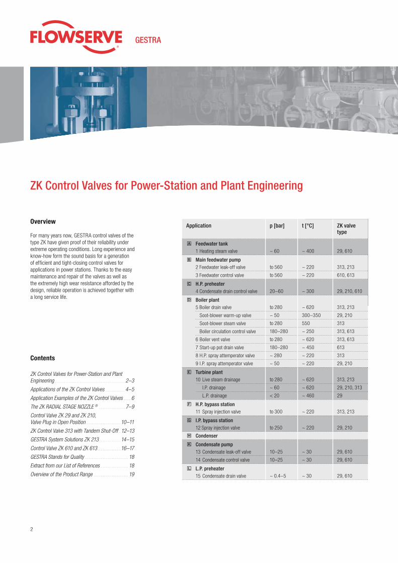
For many years now, GESTRA control valves of the type ZK have given proof of their reliability under extreme operating conditions. Long experience and know-how form the sound basis for a generation of effi cient and tight-closing control valves for applications in power stations. Thanks to the easy maintenance and repair of the valves as well as the extremely high wear resistance afforded by the design, reliable operation is achieved together with a long service life.
Contents
ZK Control Valves for Power-Station and Plant Engineering. . . . . . . . . . . . . . . . . . . . . . . . . . . . . . . . . . . . . . . . . . . . . . . . . . . . . . . .2–3
Applications of the ZK Control Valves . . . . . . . . . . . . . . . 4–5
Application Examples of the ZK Control Valves . . . . . . 6
The ZK RADIAL STAGE NOZZLE ® . . . . . . . . . . . . . . . . . . . . .7–9
Control Valve ZK 29 and ZK 210, Valve Plug in Open Position . . . . . . . . . . . . . . . . . . . . . . . . . . . 10–11
ZK Control Valve 313 with Tandem Shut-Off . . 12–13
GESTRA System Solutions ZK 213 . . . . . . . . . . . . . . . . . 14–15
Control Valve ZK 610 and ZK 613 . . . . . . . . . . . . . . . . . . 16–17
GESTRA Stands for Quality . . . . . . . . . . . . . . . . . . . . . . . . . . . . . . . . . . 18
Extract from our List of References . . . . . . . . . . . . . . . . . . . . . . 18
Overview of the Product Range . . . . . . . . . . . . . . . . . . . . . . . . . . . 19
Einbauort / Ventil p [bar] t [°C] ZK-Typen-schlüssel
e Turbine plant 10 Live steam drainage
I.P. drainage
L.P. drainage
f H.P. bypass station 11 Spray injection valve
g I.P. bypass station 12 Spray injection valve
h Condenser
k Condensate pump 13 Condensate leak-off valve
14 Condensate control valve
l L.P. preheater 15 Condensate drain valve
to 280
~ 60
< 20
to 300
to 250
10–25
10–25
~ 0.4–5
~ 620
~ 620
~ 460
~ 220
~ 220
~ 30
~ 30
~ 30
313, 213
29, 210, 313
29
313, 213
29, 210
29, 610
29, 610
29, 610
Application p [bar] t [°C] ZK valve type
a Feedwater tank 1 Heating steam valve
b Main feedwater pump 2 Feedwater leak-off valve
3 Feedwater control valve
c H.P. preheater 4 Condensate drain control valve
d Boiler plant 5 Boiler drain valve
Soot-blower warm-up valve
Soot-blower steam valve
Boiler circulation control valve
6 Boiler vent valve
7 Start-up pot drain valve
8 H.P. spray attemperator valve
9 I.P. spray attemperator valve
~ 60
to 560
to 560
20–60
to 280
~ 50
to 280
180–280
to 280
180–280
~ 280
~ 50
~ 400
~ 220
~ 220
~ 300
~ 620
300–350
550
~ 250
~ 620
~ 450
~ 220
~ 220
29, 610
313, 213
610, 613
29, 210, 610
313, 213
29, 210
313
313, 613
313, 613
613
313
29, 210
w w w . g e s t r a . d e 3
6
6
4 3 5
7
2 1
9
11
1415
10
13
12
8
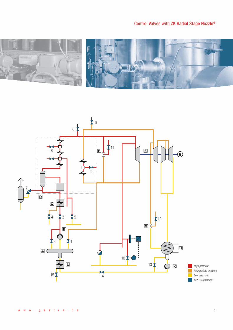
High pressure
Intermediate pressure
Low pressure
GESTRA products
d
c
f e
g
h
kl
a
b
G
Control Valves with ZK Radial Stage Nozzle®

4
1. Leak-Off Control (recirculation)
GESTRA leak-off controls for feedwater and condensate pumps represent complete systems for on/off or modulating control.
The control valve with ZK RADIAL STAGE NOZZLE®, the actuator with quick-opening function, and the control unit are optimally adapted to the operating conditions prevailing in each case.
2. Drainage and Warm-Up
The control valve with ZK RADIAL STAGE NOZZLE®, actuator, level electrode and control unit together constitute a complete system which can be perfectly adapted to the operating conditions.
Even condensate flowrates with extreme fluctu-ations are discharged by this system without any problems. Specific warming-up of certain parts of the plant can be achieved with the aid of a temper-ature acquisition system.
Applications of the ZK Control Valves
ZK control valves are suited for various fundamen-tal applications in industry and power stations:
◗ Leak-off control (recirculation)◗ Drainage and warm-up◗ Level control◗ Injection cooling◗ Steam control
GESTRA offers:
◗ Complete solutions◗ Subsystems with definite interfaces
The ZK control valve consists of a valve body and the ZK RADIAL STAGE NOZZLE® with valve plug integrated into the body to act as the control unit.
The ZK RADIAL STAGE NOZZLE® ensures a rapid and reliable adaptation to the prevailing operating conditions.
If the operating conditions in the plant are chang- ed, the control valve can be adapted to the new situation by repositioning or exchanging the radial stage nozzle. There is no need to remove the valve from the line for this purpose!
The high standard of GESTRA power station equip-ment is confirmed by a large number of references.
w w w . g e s t r a . d e 5
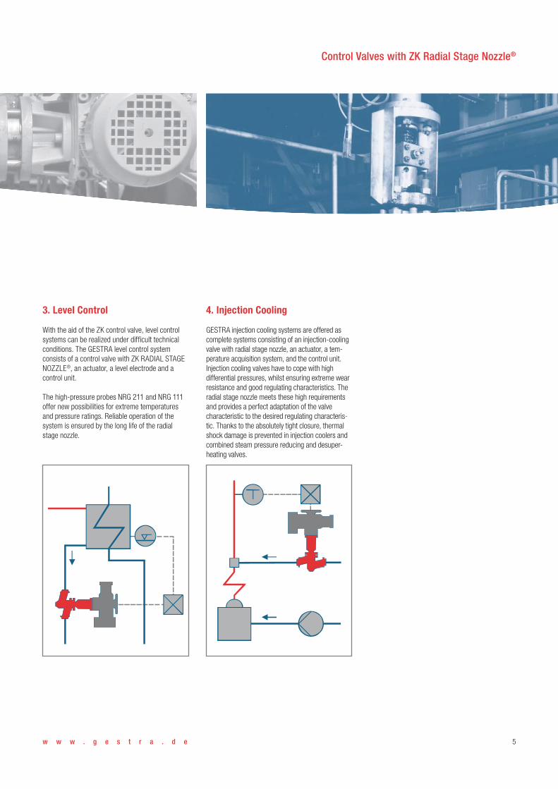
3. Level Control
With the aid of the ZK control valve, level control systems can be realized under difficult technical conditions. The GESTRA level control system consists of a control valve with ZK RADIAL STAGE NOZZLE®, an actuator, a level electrode and a control unit.
The high-pressure probes NRG 211 and NRG 111 offer new possibilities for extreme temperatures and pressure ratings. Reliable operation of the system is ensured by the long life of the radial stage nozzle.
4. Injection Cooling
GESTRA injection cooling systems are offered as complete systems consisting of an injection-cooling valve with radial stage nozzle, an actuator, a tem-perature acquisition system, and the control unit.Injection cooling valves have to cope with high differential pressures, whilst ensuring extreme wear resistance and good regulating characteristics. The radial stage nozzle meets these high requirements and provides a perfect adaptation of the valve characteristic to the desired regulating characteris-tic. Thanks to the absolutely tight closure, thermal shock damage is prevented in injection coolers and combined steam pressure reducing and desuper-heating valves.
Control Valves with ZK Radial Stage Nozzle®

6
Application Examples of the ZK Control Valves
Leak-off valve ZK 213 with compact electro-hydraulic actuator
H.P. preheater in a nuclear power station equipped with a condensate drain control valve type ZK 29
Drain control station using ZK 29 valves with electrical actuator
ZK 213 as spray injection valve in a high-pressure bypass station

w w w . g e s t r a . d e 7
Automatic Control For drainage purposes, the valve can alternatively be used as a hand control valve. In this case, the radial stage nozzle not only acts as a throttling unit, but also provides the function of thermodynamic control.
For this purpose, the control valve is adjusted manually once to the working point. From this time on, the condensate flowrate is determined by the thermal state of the condensate in the nozzle system (cold condensate / boiling hot condensate) without any further modification of the cross-sec-tional area. The valve is therefore also suitable for varying operational conditions.
The ZK RADIAL STAGE NOZZLE®
Operating Principle
Patented both in Germany and abroad, the ZK RADIAL STAGE NOZZLE® consists of several sleeves with a large number of radial orifices. The orifices are arranged in parallel, but are shifted from sleeve to sleeve so that they part-ly overlap, forming nozzles mounted in series with intermediate flash chambers.
The flow through the radial stage nozzle is deter-mined by the valve plug. Depending on its position, the individual stage nozzles are either partially or completely set free. The valve plug and the seat together form the shut-off unit of the radial stage nozzle. Due to the successive expansion in the flash chambers, the pressure differential across the cross-sectional flow area of the valve is reduced to a minimum.
Various stage nozzles and valve plugs are available to account for the pressure drop in a particular application. For extremely high pressure gradients, control valves with tandem shut-off are applied.
Due to the special design of the ZK RADIALSTAGE NOZZLE®, the sound level is reduced to a minimum. As a result of the expansion through a multitude of individual nozzles, the sound level is normally below 85 dB(A) within the entire control range of the valve.
ZK 29 radial stage nozzle with special valve plug
Valve plug of ZK 29 in control position
Regulating characteristic of the ZK RADIAL STAGE NOZZLE®
Flow
rate
m°
Differential pressure, assuming discharge to atmospheric pressure
Cold water
Boiling water
Self-
regu
latin
g ra
nge
Sectional drawing of ZK 29 radial stage nozzle
Valve plug
Control edge
Orifices of sleeve insert (shown without sleeves being shifted)
Flash chambers (sleeves shifted, orifices partly overlapping)
Seat
Control Valves with ZK Radial Stage Nozzle®

8
The ZK RADIAL STAGE NOZZLE®
Technical Properties
ZK control valves are designed to meet the highest operational requirements. They offer a number of special features in comparison with conventional control valves.
◗ Extreme wear resistanceThe successive expansion of the fluid in the throt-tling sleeves of the radial stage nozzle produces a considerable reduction in pressure drop across the cross-sectional flow area. Special design details at the seating surfaces ensure safe and reliable valve operation. In addition, the mass flow is split up into many partial flows.
◗ Leakage ratesThe following leakage rates apply, depending on the valve type:FCI 70-2-2003, at leastclass V (test procedure B) andclass VI (test procedure C) andEN 12266-1, leakage rate A
◗ Variable valve characteristicsFor the ZK control valves, stage nozzles are availa-ble with linear or equal-percentage characteristics. A subsequent change is possible by repositioning throttling sleeves (orifices) or by exchanging the complete nozzle insert.
◗ Easy installation and inspectionThe entire nozzle insert, including seat, can be completely dismantled without the need for any specialist work and without removing the valve body from the line.
◗ Tandem shut-offControl valves for an extremely high pressure gradient are provided with a tandem shut-off (dual seat). In this way, the ZK control valve combines the functions of a conventional shut-off valve and a control valve, even for very high pressures.
◗ Low sound levelThe continuous reduction of the flow velocity in the radial stage nozzle ensures a low sound level, usually a maximum of 85 dB(A) within the valve’s control range. For differential pressures up to Δp
max 100 bar, the sound level is even below
80 dB(A).
◗ Different capacity rangesThe k
vs values can be adapted to the operating
conditions by repositioning or exchanging the radial stage nozzle. Intermediate lift positions of the valve plug can thus be avoided.
The complete ZK product range offers kvs values
from 0.5 m³/h to 969 m³/h.By exchanging the internals, it is possible to adjust ZK control valves to account for changes in differential pressure.
◗ ActuatorsZK control valves can be used with most types of actuators available on the market.

w w w . g e s t r a . d e 9
Cross-sectional flow area
Position of the sleeves for linear characteristic
Position of the sleeves for equal-percentage characteristic Linear characteristic
Valve lift [%]
k v [%
]
Equal-percentage characteristic
Changing the valve characteristics using the ZK 29 as an example
10090807060504030201000
10
20
30
40
50
60
70
80
90
100
Control Valves with ZK Radial Stage Nozzle®
10
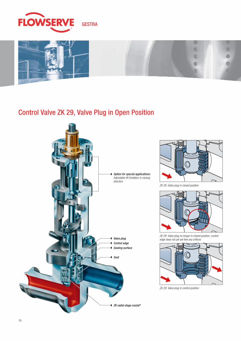
Control Valve ZK 29, Valve Plug in Open Position
ZK 29: Valve plug in closed position
ZK 29: Valve plug no longer in closed position; control edge does not yet set free any orifices
ZK 29: Valve plug in control position
Valve plug
Option for special applications: Adjustable lift limitation in closing direction
Control edge
Sealing surface
Seat
ZK radial stage nozzle®

w w w . g e s t r a . d e 11
Control Valve ZK 29
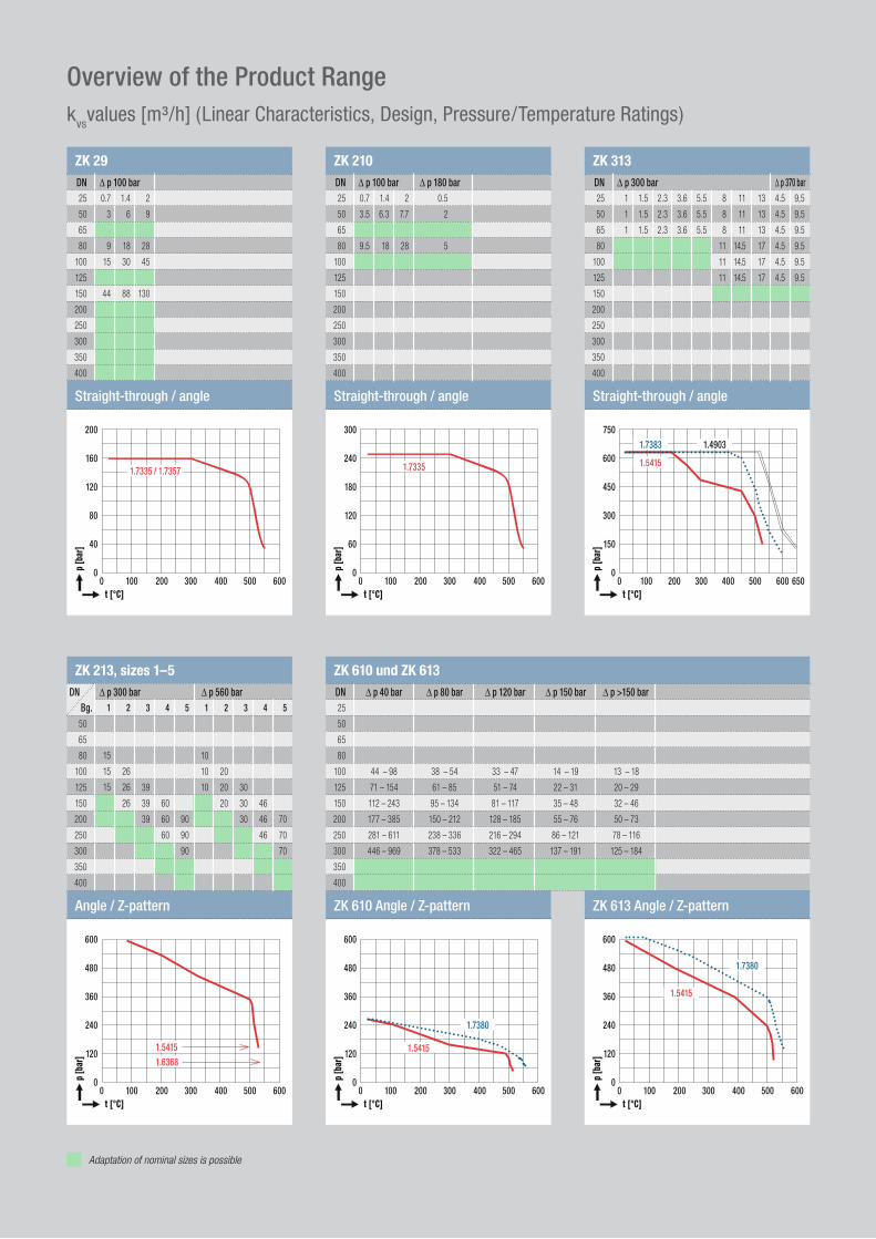
PN 160Δpmax 100 bar (1450 psi)kvs 0.7 – 130 m3/h
With its permissible differential pressure of 100 bar, the ZK 29 control valve covers a large range of k
vs values.
The valve plug and seat of a control valve are as a rule subjected to very high flow velocities during the opening and closing processes. To reduce this effect, the valve plug of the ZK control valve is provided with a special control edge above the seating surface.
At the beginning of the opening process, the plug lifts off the seat, yet the flow admitted is very low. Only once a certain lift has been reached, and
hence a large annular channel has been opened between the seat of the valve and the sealing surface of the plug, are the annular rings of the radial stage nozzle set free one after the other by the control edge.
During the closing process, the flow is first con-siderably reduced by the control edge and then the sealing surface of the plug reaches the seat to close the valve completely.
Connections
Actuators
Body material
Butt-weld ends, socket-weld ends, flanged ends (EN, ASME)
Electric (rotary, linear or lever actuator), pneumatic, handwheel
DN 25-50: 13 CrMo 4 4 (1.7335)
DN 80-150: GS-17 CrMo 5 5 (1.7357)
Other butt-weld ends and body materials on request
Control Valve ZK 210
PN 250Δpmax 100 bar (1450 psi))kvs 0.7 – 28 m3/hΔpmax 180 bar (2610 psi)kvs 0.5 – 5 m3/h
The control valve ZK 210 supplements the valve type ZK 29 primarily by extending the pressure rating to PN 250.
An additional radial stage nozzle arranged down-stream makes it possible to overcome pressure differentials Δp
max of up to 180 bar, thus closing
the gap to the existing high-pressure types. In comparison to the ZK 29, the required actuator forces are lower.
By exchanging the internals, pressure differentials of Δp
max= 100 bar or Δp
max = 180 bar can be
achieved. The ZK 210 offers the possibility of adjusting for various k
vs values and characteristics
at a later time, by rotating the stage nozzle.
Connections
Actuators
Body material
Butt-weld ends, socket-weld ends, flanged ends (EN, ASME)
Electric (rotary or linear actuator), pneumatic, handwheel
13 CrMo 4 4 (1.7335)
Other butt-weld ends and body materials on request
The ZK 29 offers the possibility of adjusting for various k
vs values and characteristics at a later
time, by rotating the stage nozzle.
Control Valves with ZK Radial Stage Nozzle®

12
Control Valve ZK 313 with Tandem Shut-Off
ZK 313: Valve plug in closed position
ZK 313: Valve plug no longer in closed position; valve cone still in closed position, control edge does not yet set free any orifices
ZK 313: Valve plug in control position
Actuator
Valve plug
Disc springs
Valve cone
ZK radial stage nozzle®
Secondary seat
Main seat

13
Control Valve ZK 313
PN 630 & Class 2500Δpmax 40 barkvs 20 – 46 m3/hΔpmax 300 barkvs 1 – 17 m3/hΔpmax 370 barkvs 4.5 – 9.5 m3/h
The control valve ZK 313 is also available as an ASME version as per ASME B 16.34. Due to the tandem shut-off, it combines the function of a conventional isolating valve and control valve, and offers long service lifetimes. The leakage rates are in accordance with the highest EN and FCI clas-sifications.
At the beginning of the opening process, first the valve plug is lifted off the main seat, but the valve
cone follows only after a certain lift. At the moment of closing and at the beginning of opening, the flow velocity at the valve seat is therefore zero, which means that wire drawing is prevented. Through the use of the steel type 1.4903 / A 182 F91 and special seat materials, the ZK 313 permits a maximum temperature of 620 ˚C. The ZK 313 valve with additional nozzle can be used for differential pressures up to Δp
max 370 bar.
Connections
Actuators
Body material
Butt-weld ends, socket-weld ends (EN, ASME)
Electric (rotary, linear or lever actuator), hydraulic, pneumatic, handwheel
16 Mo 3 (1.5415), A 182 F1
10 CrMo 9 10 (1.7383), A 182 F 22
X10 CrMoVNb 9 1 (1.4903), A 182 F 91
Standard nozzle Δpmax
300 bar / 4350 psi Special nozzle Δpmax
370 bar / 5365 psi (only angle-type design)
Special nozzle Δpmax
40 bar / 580 psi (without tandem seat)
Nozzle Versions for ZK 313
Control Valves with ZK Radial Stage Nozzle®

14
GESTRA System Solutions ZK 213
Leak-off control consisting of:
◗ ZK 213-E4/40 DN 200 with 6-stage nozzle and tandem seat◗ Hydraulic actuator with opening spring◗ Control cabinet with SIEMENS S7 PLC◗ GESTRA software with stored characteristic for leak-off valves
ZK 213 with tandem shut-off Δpmax
560 bar (8120 psi)
Disc springs
Cone
Plug
Tandem seat
Main seat

w w w . g e s t r a . d e 15
Control Valve ZK 213
Δpmax 300 bar (4350 psi)kvs 10 – 90 m3/hΔpmax 560 bar (8120 psi)kvs 10 – 70 m3/h
The tandem shut-off of the control valve type ZK 213 ensures stable and low-wear operation as a control and shut-off valve for a pressure drop of Δp
max 300 bar or Δp
max 560 bar.
For this control valve, the maximum differential pressures of Δp
max 300 bar or Δp
max 560 bar depend
on the design. A subsequent change is possible by exchanging the internals. The two additional throttling elements fitted in the high-pressure version provide effective protection against wear. Due to the tandem shut-off, it combines the functions of a conventional isolating valve and control valve, and offers long serv-
ice lifetimes. The leakage rates are in accordance with the highest EN and FCI classifications.
Connections
Actuators
Body material
Butt-weld ends (EN, ASME)
Electric (rotary, linear or lever actuator), hydraulic
16 Mo 3 (1.5415)
15 NiCuMoNb 5 (1.6368, WB 36)
ZK 213 internals when new
Internals of a leak-off valve ZK 213, DN 100, after 13 years of operation withp
1 = 374 bar (5420 psi), p
2 = 11 bar (159.5 psi), t = 172 °C, m° = 35 kg/s
Control Valves with ZK Radial Stage Nozzle®

16
ZK radial stage nozzle®, 1–5 stagesValve plug
Control Valve ZK 610 and ZK 613
Control edge
Seat
Body forging
Assembly flange
1-stage expansion
2-stage expansion
Modular System of the ZK Radial Stage Nozzle® for ZK 610, ZK 613The multi-stage pressure drop is adapted precisely to suit the operating conditions.

w w w . g e s t r a . d e 17
Control Valve ZK 610, ZK 613
ZK610, PN 250ZK613, PN 630
Δpmax 40 bar – Δpmax 250 bar (3625 psi)kvs 13 – 969 m3/h
The control valve types ZK 610 and ZK 613 round off the ZK valve range with large k
vs values. Thanks
to the modular design, it is possible to adapt the throttling units optimally to the operating condi-tions. In addition, leakage-free pressure balancing can be used to reduce the actuating forces.
As for the ZK 29, the seating surfaces are pro-tected against high flow velocities by means of a control edge at the valve plug. This design measure achieves the highest leakage-rate classifications
according to EN and FCI with long service lifetimes. The entire ZK radial stage nozzle® including seat is easy to exchange, ensuring the highest level of availability.
Connections
Actuators
Body material
Butt-weld ends (EN, ASME)Electric (rotary or linear actuator), hydraulic, pneumatic
C22.8 (1.0460)
16 Mo 3 (1.5415)
10 CrMo 9 10 (1.7380)
Other body materials on request
3-stage expansion 5-stage expansion4-stage expansion
Control Valves with ZK Radial Stage Nozzle®

18
GESTRA Stands for Quality
Quality is our Strength
For GESTRA, the concept of “Quality” not only includes the product itself, but applies equally to planning, handling and service. It is our aim to recognize and eliminate the sources of potential errors during all phases of order processing by means of comprehensive internal strategies. The ideal basis for this is a quality management system in accordance with EN ISO 9000. Of the three possible levels, our quality assurance system
achieved certifi cation according to EN ISO 9001. The high quality standard of GESTRA products has been confi rmed time and time again through a large number of recognized type-approvals issued by TÜV (German Technical Supervisory Associ-ation), Germanischer Lloyd, Lloyd’s Register of Shipping and many other classifi cation societies. The company thus also fulfi ls the conditions of the new Pressure Equipment Directive.
Extract from our List of References
Loy Yang B Power Station . . . . . . . . . . . . AustraliaCollie Power Station . . . . . . . . . . . . . . . . . . . . . AustraliaEnergy Brix Australia . . . . . . . . . . . . . . . . . . . . Australia AUSTRIAN ENERGY . . . . . . . . . . . . . . . . . . . . . . . . AustriaElectrabel . . . . . . . . . . . . . . . . . . . . . . . . . . . . . . . . . . . . . . BelgiumJP Elektroprivreda . . . . . . . . . . . . . . . . . . . . . . . . . . . BosniaTractebel . . . . . . . . . . . . . . . . . . . . . . . . . . . . . . . . . . . . . . . . . . . BrazilBecancour Power Plant . . . . . . . . . . . . . . . . . CanadaMethanex . . . . . . . . . . . . . . . . . . . . . . . . . . . . . . . . . . . . . . . . . . . ChileBASF YPC Project Nanjing . . . . . . . . . . . . . . . . ChinaWaigaoqiao . . . . . . . . . . . . . . . . . . . . . . . . . . . . . . . . . . . . . . . ChinaINA Raffi nerie . . . . . . . . . . . . . . . . . . . . . . . . . . . . . . . . . . Croatia ̌CEZ . . . . . . . . . . . . . . . . . . . . . . . . . . . . . . . . . . . . . . . . . . . . . . . .CzechiaŠkoda . . . . . . . . . . . . . . . . . . . . . . . . . . . . . . . . . . . . . . . . . . . . .CzechiaElsam . . . . . . . . . . . . . . . . . . . . . . . . . . . . . . . . . . . . . . . . . . .DenmarkTeollisuuden Voima Oy . . . . . . . . . . . . . . . . . .FinnlandEDF . . . . . . . . . . . . . . . . . . . . . . . . . . . . . . . . . . . . . . . . . . . . . . . . . FranceALSTOM . . . . . . . . . . . . . . . . . . . . . . . . . . . . . . . . . . . . . . GermanyBASF . . . . . . . . . . . . . . . . . . . . . . . . . . . . . . . . . . . . . . . . . . . . GermanyBayer . . . . . . . . . . . . . . . . . . . . . . . . . . . . . . . . . . . . . . . . . . . . GermanyBEWAG . . . . . . . . . . . . . . . . . . . . . . . . . . . . . . . . . . . . . . . . GermanyClariant . . . . . . . . . . . . . . . . . . . . . . . . . . . . . . . . . . . . . . . . GermanyE.ON . . . . . . . . . . . . . . . . . . . . . . . . . . . . . . . . . . . . . . . . . . . . . GermanyEnBW . . . . . . . . . . . . . . . . . . . . . . . . . . . . . . . . . . . . . . . . . . . GermanyHitachi Power Europe . . . . . . . . . . . . . . . . . . GermanyKSB Pumpen . . . . . . . . . . . . . . . . . . . . . . . . . . . . . . . GermanyRWE Power AG . . . . . . . . . . . . . . . . . . . . . . . . . . . . GermanySIEMENS PG . . . . . . . . . . . . . . . . . . . . . . . . . . . . . . . . GermanySTEAG . . . . . . . . . . . . . . . . . . . . . . . . . . . . . . . . . . . . . . . . . GermanySulzer Pumpen . . . . . . . . . . . . . . . . . . . . . . . . . . . . . GermanySWB . . . . . . . . . . . . . . . . . . . . . . . . . . . . . . . . . . . . . . . . . . . . . GermanyVattenfall . . . . . . . . . . . . . . . . . . . . . . . . . . . . . . . . . . . . . . GermanyVolkswagen . . . . . . . . . . . . . . . . . . . . . . . . . . . . . . . . . . GermanyWeller Pumpen . . . . . . . . . . . . . . . . . . . . . . . . . . . . . GermanyBHEL . . . . . . . . . . . . . . . . . . . . . . . . . . . . . . . . . . . . . . . . . . . . . . . . . . .IndiaTjiwi Kimia . . . . . . . . . . . . . . . . . . . . . . . . . . . . . . . . . . . IndonesiaAnsaldo . . . . . . . . . . . . . . . . . . . . . . . . . . . . . . . . . . . . . . . . . . . . . . . . ItalyENEL . . . . . . . . . . . . . . . . . . . . . . . . . . . . . . . . . . . . . . . . . . . . . . . . . . . . ItalyIncheon Power Plant . . . . . . . . . . . . . . . . . . . . . . . . . KoreaPanglima Power . . . . . . . . . . . . . . . . . . . . . . . . . . . MalaysiaEPZ . . . . . . . . . . . . . . . . . . . . . . . . . . . . . . . . . . . . . . . . . NetherlandsElektrownia Kozienice . . . . . . . . . . . . . . . . . . . . . PolandRibatejo Power Plant . . . . . . . . . . . . . . . . . . . . . PortugalAL Shuweihat . . . . . . . . . . . . . . . . . . . . . . . . . Saudi ArabiaEskom . . . . . . . . . . . . . . . . . . . . . . . . . . . . . . . . . . . . .South AfricaCampo de Gibraltar . . . . . . . . . . . . . . . . . . . . . . . . . . . SpainKernkraftwerk Trillo . . . . . . . . . . . . . . . . . . . . . . . . . . . SpainSagunto . . . . . . . . . . . . . . . . . . . . . . . . . . . . . . . . . . . . . . . . . . . . . SpainC4 ENERGI AB . . . . . . . . . . . . . . . . . . . . . . . . . . . . . . .SwedenSSAB . . . . . . . . . . . . . . . . . . . . . . . . . . . . . . . . . . . . . . . . . . . . .SwedenKernkraftwerk Leibstadt . . . . . . . . . .SwitzerlandKuo Kuang Power . . . . . . . . . . . . . . . . . . . . . . . . . . . TaiwanBritish Energy . . . . . . . . . . . . . . . . . . . . . . . . . . . . . . . . . . . . . . . . .UKAlabama Power . . . . . . . . . . . . . . . . . . . . . . . . . . . . . . . . . . . USAAmeren UE . . . . . . . . . . . . . . . . . . . . . . . . . . . . . . . . . . . . . . . . . . USACon Edison . . . . . . . . . . . . . . . . . . . . . . . . . . . . . . . . . . . . . . . . . . USAElectric Energy . . . . . . . . . . . . . . . . . . . . . . . . . . . . . . . . . . . . USATVA . . . . . . . . . . . . . . . . . . . . . . . . . . . . . . . . . . . . . . . . . . . . . . . . . . . . . USAPhu My . . . . . . . . . . . . . . . . . . . . . . . . . . . . . . . . . . . . . . . . . . Vietnam
On request, we will gladly provide references for other countries and customers.
w w w . g e s t r a . d e 19
Angle / Z-pattern
ZK 213, sizes 1–5
50
65
80
100
125
150
200
250
300
350
400
Δ p 300 barDN1
15
15
15
2
26
26
26
3
39
39
39
4
60
60
60
5
90
90
90
1
10
10
10
2
20
20
20
3
30
30
30
4
46
46
46
5
70
70
70
ZK 610 und ZK 613
25
50
65
80
100
125
150
200
250
300
350
400
Δ p 40 barDN
44 – 98
71 – 154
112 – 243
177 – 385
281 – 611
446 – 969
750
600
450
300
150
00 100 200 300 400 500 600
p [b
ar]
t [°C]
Straight-through / angle
ZK 313
25
50
65
80
100
125
150
200
250
300
350
400
Δ p 300 barDN1
1
1
1.5
1.5
1.5
2.3
2.3
2.3
3.6
3.6
3.6
5.5
5.5
5.5
8
8
8
11
11
11
11
11
11
14.5
14.5
14.5
13
13
13
17
17
17
4.5
4.5
4.5
4.5
4.5
4.5
9,5
9,5
9.5
9.5
9.5
9.5
Δ p 370 bar
ZK 29
25
50
65
80
100
125
150
200
250
300
350
400
Δ p 100 barDN0.7
3
9
15
44
1.4
6
18
30
88
2
9
28
45
130
Straight-through / angle
200
160
120
80
40
00 100 200 300 400 500 600
p [b
ar]
t [°C]
1.7335 / 1.7357
300
240
180
120
60
00 100 200 300 400 500 600
p [b
ar]
t [°C]
1.7335
Straight-through / angle
ZK 210
25
50
65
80
100
125
150
200
250
300
350
400
Δ p 100 barDN Δ p 180 bar0.7
3.5
9.5
1.4
6.3
18
2
7.7
28
0.5
2
5
Bg.Δ p 560 bar
600
480
360
240
120
00 100 200 300 400 500 600
p [b
ar]
t [°C]
1.54151.6368
Δ p 80 bar Δ p 120 bar Δ p 150 bar Δ p >150 bar
38 – 54
61 – 85
95 – 134
150 – 212
238 – 336
378 – 533
33 – 47
51 – 74
81 – 117
128 – 185
216 – 294
322 – 465
14 – 19
22 – 31
35 – 48
55 – 76
86 – 121
137 – 191
13 – 18
20 – 29
32 – 46
50 – 73
78 – 116
125 – 184
600
480
360
240
120
00 100 200 300 400 500 600
p [b
ar]
t [°C]
600
480
360
240
120
00 100 200 300 400 500 600
p [b
ar]
t [°C]
ZK 610 Angle / Z-pattern ZK 613 Angle / Z-pattern
1.5415
1.7380
1.5415
1.7380
Overview of the Product Rangekvsvalues [m³/h] (Linear Characteristics, Design, Pressure/Temperature Ratings)
Adaptation of nominal sizes is possible
1.7383
1.5415
1.4903
650

With Energy into the Future
GESTRA AGMünchener Str. 77, D-28215 BremenP.O. Box 10 54 60, D-28054 BremenTelephone +49 (0) 421-35 03-0Telefax +49 (0) 421-35 03-393E-mail [email protected] www.gestra.de
810742-02/407 EMA · © 2007 · GESTRA AG · Bremen · Printed in Germany
Top Related