


Languages
Pages
Legal

IIII
•
IIIIIIIIIIIIII
CONF
Design 378B
Apollo Extension Systems —Lunar Excursion Module
Phase B Final Report
N75-7U5901
— '•«-s»e-«.»is«Li MI.UDE-D, (THRU)
\SA-CR-70910) APOLLO EXTENSION SYSTEMS -LUNAR EXCURSION MODULE. VOLUME 2, PHASE B:
I.1OARY DEFINITION STUDIES SUMMARY^inal Report (Grumman Aircraft Engineering Unclas
81 p 00/98 23593
Vol. II Preliminary Definition Studies Summary (U)
CONFIDENTIAL
Copy No
Apollo Extension Systems— Lunar Excursion ModulePhase B Final Report
to
National Aeronautics and Space AdministrationManned Spacecraft Center
Advanced Spacecraft Technology DivisionHouston, Texas 77058
byGrumman Aircraft Engineering Corporation
Bethpage, New York
This documeRtRontains information affecting the national defense of theUnited States wifffathe meaning of the Espionage Laws, Title 18, U S C ,Sections 793 and 794^^^ransmis,sion or revelation of^hich in any mannerto an unauthorized persorr^atMrphibited by law
Group 41owngraded^^DeclasdKd after 12 Yean
Vol. II Prel iminary Definit ion Studies Summary
Contract No. NAS 9-4983ASR 378B
8 December 1965

PrefaceX,
This report presents the results of the Phase"B" Preliminary Definition Study (ContractNAS 9-4983) of the Lunar Excursion Module(LEM) and its modifications and additions, asnecessary, for use in the Apollo ExtensionSystems (AES). This use includes a Laboratoryfor Earth and lunar orbital missions, and aShelter, a Taxi and a Truck for extended-staylunar surface missions. The overall objective ofthis study was to conduct sufficient analysesto provide a basis for selection by NASA of asingle concept for each mission for final defini-tion and development.
The study results are distributed in the vol-umes listed below in the following manner:Volume I contains a summary of the Prelimin-ary Project Development Plan (PDP) withemphasis on estimates of the program costsand schedules. This volume was submitted on30 October 1965, one month in advance of theremaining final documentation. Volume II is abrief summary of the overall study. VolumesIII through XVI contain the design analyses,preliminary specifications, and operations an-alyses for each of the AES/LEM vehicle types.Volumes XVII through XXVI contain prelim-inary project planning data in the areas ofmanagement, manufacturing, development test-ing, and support.
It was necessary to base the preliminaryproject planning data, including estimatedcosts, on a single configuration for each of theAES/LEM vehicle types. Since these" PDP datawere required by the end of October, the con-figurations had to be selected at the mid-pointof the study, before the configuration studieshad been completed. These configurations havebeen called "baseline" configurations. The con-tinuing design analyses in the second half ofthe study* have resulted in recommendedchanges to the baseline configurations. VolumesIII through VI describe the "recommended"configurations, the baseline configurations, andsome additional alternates which were studied.It is anticipated that NASA will make a selec-tion from these configurations? and that theseselections will then be the new baseline con-figurations for the next phase of AES definitionstudies.
The scope of this study included integrationof the experimental payloads with the Shelterand Taxi, but did not include study of the inte-
gration on individual LEM Laboratory flights.At approximately the mid-point of the study, anaddendum was written with the objective ofproviding support to the NASA Mission Plan-ning Task Force for study of the Phase I Lab-oratory flights. The schedule for the addendumcalls for completion of these mission planningstudies in January, 1966. Therefore, the adden-dum efforts are not described in this report
The volumes which comprise this report areas follows:
/ Phase B Preliminary Definition Plan(30 Oct 1965)
II Preliminary Definition StudiesSummary
III Phase I LaboratoryDesign Analysis Summary
IV Phase II LaboratoryDesign Analysis Summary
V Shelter Design Analysis SummaryVI Taxi Design Analysis Summary
VII Truck Design Analysis SummaryVIII Phase I Laboratory
Master End Item SpecificationIX Phase II Laboratory
Master End Item SpecificationX Shelter Master End Item Specification
XI Taxi Master End Item SpecificationXII Phase I Laboratory Experimental
Payload Performance &Interface Specification
XIII Phase II Laboratory ExperimentalPayload Performance &Interface Specification
XIV Shelter Experimental PayloadPerformance & Interface Specification
XV Taxi Experimental PayloadPerformance & Interface Specification
XVI Prelaunch & Mission OperationsXVII Manufacturing Plan
XVIII AES Modifications to LEMQuality Control Program Plan
XIX Ground Development Test PlanXX Support Equipment Specification
XXI Facilities PlanXXII Support Plan
XXIII Transportation PlanXXIV Training Equipment RequirementsXXV Support Equipment Requirements
XXVI Management Plan
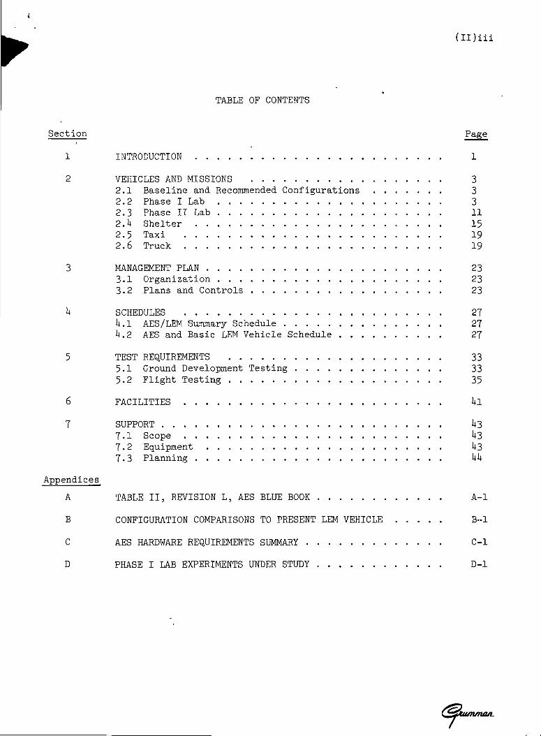
TABLE OF CONTENTS
(H)iii
Section Page
1 INTRODUCTION 1
2 VEHICLES AND MISSIONS 32.1 Baseline and Recommended Configurations 32.2 Phase I Lab 32.3 Phase II Lab 112.U Shelter 152.5 Taxi 192.6 Truck 19
3 MANAGEMENT PLAN 233.1 Organization 233.2 Plans and Controls 23
U SCHEDULES 27h.I AES/LEM Summary Schedule 27k.2 AES and Basic LEM Vehicle Schedule 27
5 TEST REQUIREMENTS 335-1 Ground Development Testing 335.2 Flight Testing 35
6 FACILITIES Ul
7 SUPPORT h37.1 Scope U37.2 Equipment U37.3 Planning kh
Appendices
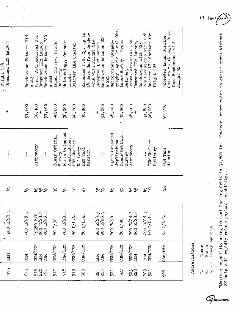
A TABLE II, REVISION L, AES BLUE BOOK A-l
B CONFIGURATION COMPARISONS TO PRESENT LEM VEHICLE B-l
C AES HARDWARE REQUIREMENTS SUMMARY C-l
D PHASE I LAB EXPERIMENTS UNDER STUDY D-l
(Il)iv
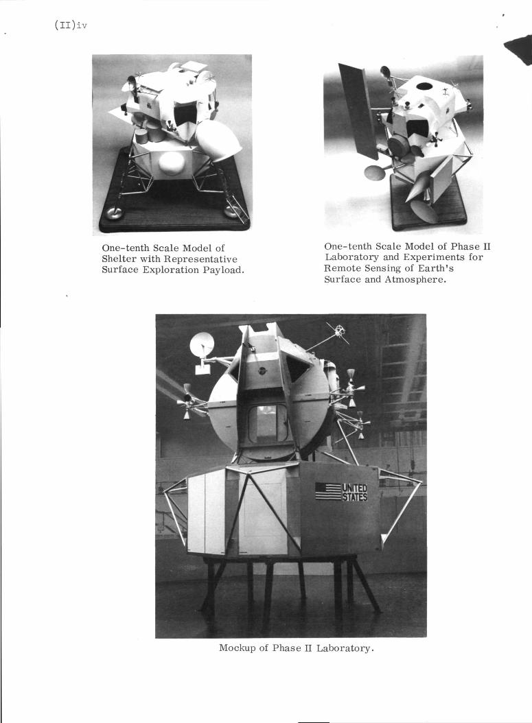
One-tenth Scale Model ofShelter with RepresentativeSurface Exploration Pay load.
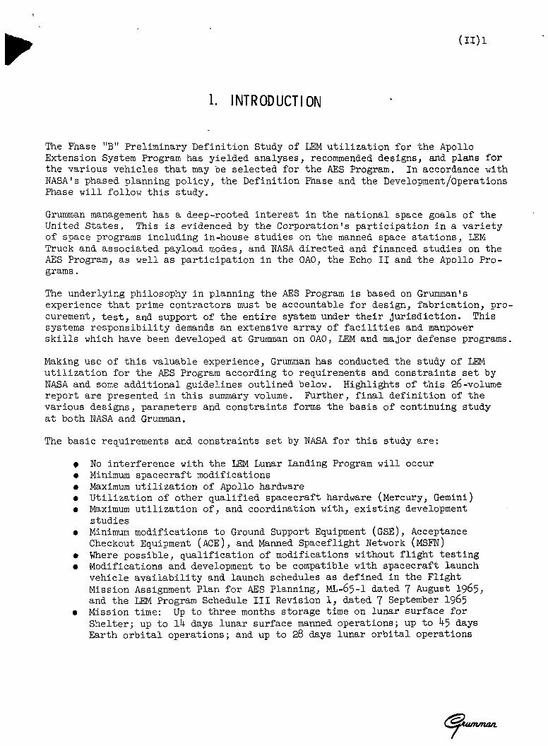
One-tenth Scale Model of Phase IILaboratory and Experiments forRemote Sensing of Earth'sSurface and Atmosphere.
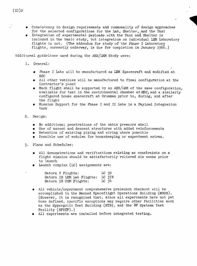
Mockup of Phase II Laboratory.
(11)1
1. INTRODUCTION
The Phase "B" Preliminary Definition Study of LEM utilization for the ApolloExtension System Program has yielded analyses, recommended designs, and plans forthe various vehicles that may be selected for the AES Program. In accordance withNASA's phased planning policy, the Definition Phase and the Development/OperationsPhase will follow this study.
Grumman management has a deep-rooted interest in the national space goals of theUnited States. This is evidenced by the Corporation's participation in a varietyof space programs including in-house studies on the manned space stations, LEMTruck and associated payload modes, and NASA directed and financed studies on theAES Program, as well as participation in the OAO, the Echo II and the Apollo Pro-grams .
The underlying philosophy in planning the AES Program is based on Grumman'sexperience that prime contractors must be accountable for design, fabrication, pro-curement, test, and support of the entire system under their jurisdiction. Thissystems responsibility demands an extensive array of facilities and manpowerskills which have been developed at Grumman on OAO, LEM and major defense programs.
Making use of this valuable experience, Grumman has conducted the study of LEMutilization for the AES Program according to requirements and constraints set byNASA and some additional guidelines outlined below. Highlights of this 26-volumereport are presented in this summary volume. Further, final definition of thevarious designs, parameters and constraints forms the basis of continuing studyat both NASA and Grumman.
The basic requirements and constraints set by NASA for this study are:
• No interference with the LEM Lunar Landing Program will occur• Minimum spacecraft modifications• Maximum utilization of Apollo hardware• Utilization of other qualified spacecraft hardware (Mercury, Gemini)• Maximum utilization of, and coordination with, existing development
studies• Minimum modifications to Ground Support Equipment (GSE), Acceptance
Checkout Equipment (ACE), and Manned Spaceflight Network (MSFN)• Where possible, qualification of modifications without flight testing• Modifications and development to be compatible with spacecraft launch
vehicle availability and launch schedules as defined in the FlightMission Assignment Plan for AES Planning, ML-65-1 dated 7 August 1965,and the LEM Program Schedule III Revision 1, dated 7 September 1965
• Mission time: Up to three months storage time on lunar surface forShelter; up to Ik days lunar surface manned operations; up to ^5 daysEarth orbital operations; and up to 28 days lunar orbital operations
(H)2
• Consistency in design requirements and commonality of design approachesfor the selected configurations for the Lab, Shelter,^and the Taxi
• Integration of experimental payloads with the Taxi and Shelter isincluded in the basic study, but integration on individual LEM Laboratoryflights is not. (The addendum for study of the Phase I Laboratoryflights, currently underway, is due for completion in January 1966.)
Additional guidelines used during the AES/LEM Study were:
1. General:
• Phase I Labs will be manufactured as LEM Spacecraft and modified atKSC
• All other vehicles will be manufactured to final configuration at theContractor's plant
• Each flight shall be supported by an AES/LEM of the same configuration,available for test in the environmental chamber at MSC, and a similarlyconfigured house spacecraft at Grumman prior to, during, and afterthe flight
• Mission Support for the Phase I and II Labs is a Payload Integrationtask
2. Design:
• Wo additional penetrations of the cabin pressure shell• Use of ascent and descent structures with added reinforcements• Retention of existing piping and wiring where possible• Possible use of modules for housekeeping or experiment extras.
3. Plans and Schedules:
• All demonstrations and verifications existing as constraints on aflight mission should be satisfactorily relieved six weeks priorto launch
• Launch complex (LC) assignments are:
Saturn V Flights: LC 39Saturn IB LEM Lab Flights: LC 3?BSaturn IB CSM Flights: LC 34
• All vehicle/experiment comprehensive prelaunch checkout will beaccomplished in the Manned Spaceflight Operations Building (MSOB).(However, it is recognized that, since all experiments have not yetbeen defined, specific exceptions may require other facilities suchas the Hypergolic Test Building (HTB), and the RF Systems TestFacility (RFSTF).)
• All experiments are installed before integrated testing.

(11)3
BC 3
2. VEHICLES & MISSIONS
2.1 BASELINE AND RECOMMENDED CONFIGURATIONS• /
To provide NASA with a9preliminary definition of the complete program requiredfor the AES/LEM schedules, one configuration was selected for each of the Phase Iand Phase II Labs, the Shelter, and the Taxi at the mid-study point. These con-figurations were identified as "baseline configurations" and described in theMid-Term Report dated 20 September 1965, and the Preliminary Project DevelopmentPlan (PDP), Volume I of this report, submitted on 30 October 1965. In the latterhalf of the study, these baseline configurations were modified as a result ofNASA direction and continuing vehicle design studies. These more current con-figurations are identified as "recommended configurations" and are described inthis final report of the Preliminary Definition Study. In addition, for eachof the four vehicles, various "alternates" in certain subsystem areas have beenidentified and are presented as possible candidates for NASA selection. Finally,vehicle changes required only for specific flights have been identified as "per-flight modifications" and are also presented.
The recommended configurations, described briefly in this section, are capableof performing most of the AES missions as they are presently understood. Themission-related requirements for these configurations were derived from:
• Table II (Revision L) of the Blue Book (included in Appendix A forreference)
• Experiment Payload requirements studied in Phase A• NASA/MSFC mission descriptions• Preliminary results of the Phase B Addendum study of Experiment Payload
Integration.
The recommended vehicle designs keep the present LEM intact to the maximum extentpossible. Increases in subsystem capability are made by additions where possible,rather than modifications.
The LEM-Phase I Lab modification flow is represented pictorially in Fig. 2-1.General equipment arrangements for the Phase I Lab, Phase II Lab, Shelter and Taxiare shown in Figs. 2-2 through 2-5, respectively. Further descriptions of thesevehicles follow. In addition, itemized configuration comparisons to the presentLEM vehicle are included in Appendix B. A summary of AES hardware requirementsitemizing degree of modification by subsystem, by vehicle, is included in AppendixC.
The LEM Truck design study effort has been limited to maintaining the Truck con-sistent in concept with the other vehicles, particularly the Shelter.
2.2 PHASE I LAB
2.2.1 Mission
The Phase I Lab is a minimum-modification LEM used as an Earth and lunar orbitallaboratory to provide experiment support for mission durations of up to Ik days.
This vehicle operates in conjunction with the Apollo Command and Service Module.Its launch vehicle is a Saturn IB or Saturn V. '
' "\ --
The orbital characteristics of the Phase I Lab missions are described in AppendixA. These include low-altitude Earth orbits of varying inclination, synchronousEarth orbits, and low-inclination lunar orbits. Experiment-imposed mission re-quirements were selected from a broad survey of the Phase A studies and from dataavailable from the early portion of the Addendum I (Experiment Payload IntegrationStudy) to this Phase B study. Experiments identified by NASA for the Phase I Labflights, and which are being studied in the Addendum, are listed in Appendix D.
The accomplishment of rendezvous and/or dual launch were not included as missionimposed requirements.
2.2.2 Vehicle
2.2.2.1 Nature of Modifications to LEM Sybsystems
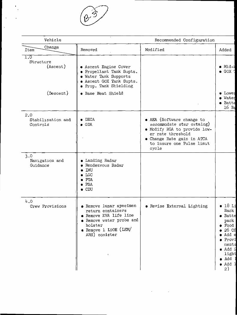
The recommended Phase I Lab configuration is a LEM with specific modifications tothe environmental control, electrical power, stabilization and control, andinstrumentation subsystems. Specific deletions and/or minor modifications arerequired to the guidance and navigation, landing gear, propulsion, communicationsand crew provisions subsystems. Deletions and modifications associated with thesesubsystem changes are required for the structure and the displays and controlssubsystem.
All modifications or changes, with reference to the present LEM configuration arelisted in Table B-l of Appendix B. In addition, Table C-l of Appendix C summa-rizes the hardware changes in terms of the degree of modification and commonalityof changes between the Phase I Lab, Phase II Lab, Shelter, and Taxi.
Significant modifications required for the Phase I Lab are:
2.2.2.2 Environmental Control
• Addition of two descent water tanks to the LEM active thermal controlsystem capacity for the lU-day mission
• Provision of Environmental Control Subsystem (ECS) capacity to rejectthe heat loads associated with the available 91.1 kw-hr of experimentenergy plus all housekeeping energy
• Cold plate area within the cabin to cool 500 watts of experiment load• Addition of five descent stage type gaseous oxygen (GOX) tanks to
enable 18 Lab repressurizations and 18 backpack charges.
2.2.2.3 Electrical Power
• Addition of 16 LEM descent batteries• Batteries actively cooled using cold rails, identical to LEM• Increased capacity of LEM Electrical Power Subsystem (EPS) from 68 kw-hr
to 274 kw-hr to provide 91.1 kw-hr for experiment use and 182.9 kw-hrfor housekeeping.

Thermal Shielding
Aft Equipment Bay
Propellant OuantityR/R Electronic?Assembly
^Helium Tankage
OOX Tankap,e
Propellant Tanks Ascent PropulsionEngine
AttitudeCoi
Ascent Stage Disassembly
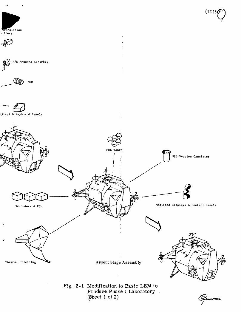
ranslationoilers
R/R Antenna Assembly
INU
iplays £, Keyboard Panels
Thermal Shielding
Mid Section Cannister
Modified Displays & Control Panels
Ascent Stage Assembly
Fig. 2-1 Modification to Basic LEM toProduce Phase I Laboratory(Sheet 1 of 2)
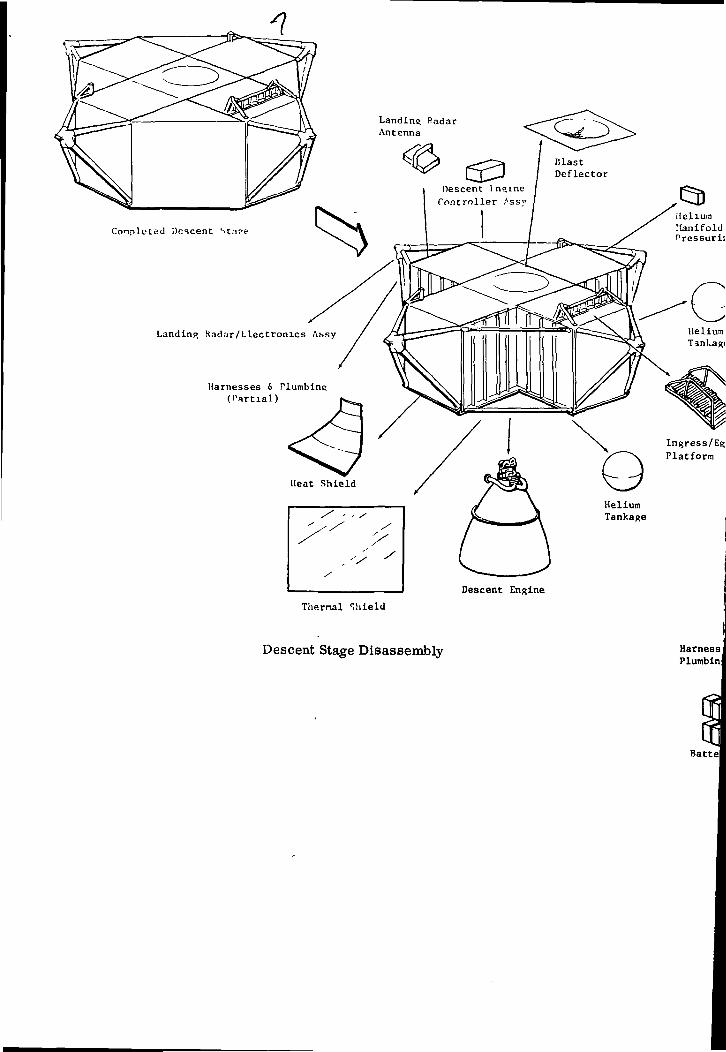
Landing PadarAntenna
BlastDeflector
Descent 1 ngmeController
Connleted Descent ''tnr
Landing Kadar/Llectronics
Harnesses & Plurablne(Partial)
HeliumTankage
Descent Engine
Thernal Shield
Descent Stage Disassembly

(11)7/8
It ion
Water Supply Batteries
ries. Lower Deck Shield
Batteries
Thermal Shieldingand Insulation
Descent Stage Assembly
Completed Descent Stage
Fig 2-1 Modification to Basic LEM toProduce Phase I Laboratory(Sheet 2 of 2)

ServiceModuleEngine
Gaseous OxygeiTanks (5)
LEM AscentStage
Spacecraft LEM Adapte:
ExperimentCanister
LEMDescentStage
S-IV B
Launch Configuration ~v

(11)9/1
(SLA)
WaterTanks(3)
ServiceModule
Plan ViewAscent Stage
Batteries (16)
CommandModule ;
PropellantTanks (4)(Empty)
Existing LEMBatteries
Plan ViewDescent Stage
0 20 40 60 80 100i i i i i i i i i iScale, in.
LEMAscentStage
LEM;DescentStage
Orbiting Configuration
Fig. 2-2 Phase I Lab RecommendedGeneral Arrangement

(11)11
2.2.2.U Stabilizatipn'& Control
• Deletion of current LEM Primary Guidance, Navigation & Control Section• Modification of current LEM Abort Guidance & Control Section, Rate Gyro
Assembly and Attitude and Translation Control Assembly for reduced pro-pellant consumption during limit cycling
• Modification of Abort Electronics Assembly programming to enable inter-facing with Alignment Optical Telescope for attitude reference updating.
2.2.2.5 Instrumentation
• Addition of a data handling section to LEM instrumentation to providerecording, storage, and transmission of experiment data.
2.2.2.6 Propulsion
• Deletion of ascent propulsion system• Deletion of descent propulsion engine and Helium tanks.
2.2.2.7 Alternates
Significant subsystem alternate configurations are also presented in Volume IIIfor the Phase I Lab environmental control, electrical power and stabilization andcontrol subsystems.
Per-flight modifications for the Phase I Lab are also presented in Volume III andinclude considerations of experiment cooling, experiment storage volume within thevehicle, stabilization and control and propulsion.
2.3 PHASE II LAB
2.3.1 Mission
The Phase II Lab, a conversion from the LEM design, is used as an Earth and lunarorbital laboratory to provide experiment support for mission durations of up toij-5 days. This vehicle also operates in conjunction with an AES Command and ServiceModule. Its launch vehicle is a Saturn IB or Saturn V.
The orbital characteristics of the Phase II Lab missions, described in Appendix A,are similar to those for the Phase I Lab, except they also include polar lunarorbits. Experiment-imposed mission requirements were selected from a broad surveyof the proposed missions and from data available from the first phase of thisstudy (Phase A).
The accomplishment of rendezvous and/or dual launch were not included as missionimposed requirements.
2.3.2 Vehicle
2.3.2.1 Nature of Modifications to LEM Subsystems
The recommended Phase II Lab configuration is a LEM with specific modificationsto the environmental control, electrical power, stabilization and control,
(11)12
instrumentation, and reaction control subsystems. Specific deletions and/or minormodifications are required to the guidance and navigation, landing gear, propulsion,reaction controls, communications and crew provisions subsystems . Deletions andmodifications associated with these subsystem changes are required for the struc-ture and the .displays and controls subsystem. The structure is also modified bythe incorporation of an airlock.
All modifications or changes, with reference to the present LEM configuration arelisted in Table B-2 of Appendix B. In addition, Table C-I of Appendix C summa-rizes the hardware changes in terms of the degree of modification and commonalityof changes between the Phase I lab, Phase II Lab, Shelter, and Taxi.
A summary of the significant modifications required for the Phase II Lab follows:
2.3.2.2 Environmental Control
• Addition of 60 sq ft of radiator area and supplemental LEM type waterboiling for the 45 -day mission
• Provision of ECS capacity capable of rejecting the heat loads associatedwith 834 kw-hr of experiment energy plus all housekeeping energy
• Cold plate area within the cabin to cool 500 watts of experiment load• A LEM ascent gaseous oxygen (GOX) tank functioning as an accumulator
to supply oxygen from the Electrical Power Subsystem (EPS) cryogenictanks and gaseous nitrogen stored in the LEM descent GOX tank, providecapacity to pressurize the airlock 44 times and recharge the backpack44 times .
2.3.2.3 Electrical Power
• Replacement of LEM batteries by two Allis Chalmers 2-kw nominal designfuel cells
• Addition of cryogenic tanks (presently being developed for the AES-CSM)for fuel cell reactants providing capacity of l680 kw-hr for a typicalmission
• Provision of Phase II Lab EPS capacity of 676 kw-hr for experiments and1004 kw-hr for housekeeping
• Addition of 60 sq ft of radiator area for fuel cell cooling.
2.3.2.4 Stabilization and Control - Same as Phase I Lab
2.3.2.5 Instrumentation - Same as Phase I Lab with a minor additional modification.
2.3.2.6 Reaction Control
• Addition of two sets of Reaction Control Subsystem (RCS) tanks to thepresent LEM capacity
• Reversal of fuel and oxidizer tank sizing due to lower oxidizer-fuel ratioof the RCS engine during minimum impulse bit firing, to produce a usabletank capacity of 1048 Ib .

Allis - ChalmersFuel Cells (2)
LEMAscentStage
Gaseous Oxygen& Water Tanks
Spacecraft LEMAdapter (SLA)
VerticalRadiators(6 Places, 120 sq ft Total)
LEMDescentStage
S-IV B
Nitrogen Tank
Electric Power SubiCryogenic Hydrogei
Launch Configuration

dditionalCS Propellant /ank (4) /
•— Z
Plan ViewAscent Stage
ServiceModule
CommandModule
LEMAscentStage
LEMDescent.^Stage
Plan ViewDescent Stage
0 20 40 60 80 100i . . . . , 1 , 1 , 1 , 1 . 1
Scale, in.
Orbiting Configuration
Fig. 2-3 Phase n Lab RecommendedGeneral Arrangement
(11)15*
2.3.2.7 Alternates
Significant alternate subsystem configurations are also presented in Volume IV forthe Phase II Lab environmental control, electrical power and stabilization andcontrol subsystems. In addition, several alternate airlock designs are presented.
Per-flight modifications for the Phase II Lab are also presented and include con-siderations of additional RCS tankage, use of the "low profile" descent stage, thedescent propulsion, and additional storage boxes, as well as incorporation of aviewfinder.
S.lj. SHEIITER
2.4.1 Mission
Significant mission characteristics of the Shelter are summarized as follows:
• Descent trajectory is_ Hohmann transfer from a CSM 80-n.mi parking orbit• Systems are activated, aligned and checked out by the astronaut prior
to separation from the CSM in parking orbit• Shelter operates in conjunction with LEM Taxi and provides capability for
a day or night manned mission on the lunar surface• Shelter is capable of unmanned lunar landing, surviving the lunar
environment in a quiescent state for periods up to three months, and thenproviding life support and scientific mission capability for the tvo LEMTaxi crewmen for periods up to 14 days
• There shall be a capability of providing status data to Earth on commandfrom the Earth during the quiescent state period of three months
• Ascent capability is not required.
2.4.2 Vehicle
2.4.2.1 Nature of Modifications to LEM Subsystems
The recommended Shelter configuration is a LEM with specific modifications to theenvironmental control, electrical power, navigation and guidance, and crew pro-visions subsystems. Specific deletions and/or minor modifications are requiredto the stabilization and control, communications, instrumentation, propulsion,and reaction control subsystems. Because of these subsystem changes, deletionsand modifications are also required for the structure and the controls anddisplays subsystem. The structure is also modified by the incorporation of anairlock.
All modifications and changes to the present LEM configuration, are listed inTable B-3 of Appendix B. In addition, a summary of the hardware modifications interms of degree of modification and commonality with the Phase I Lab, Phase IILab, Shelter, and Taxi is presented in Table 6-1 of Appendix C.
A summary of significant, required Shelter modifications follows:

(11)16
2.4.2.2 Environmental Control
• Addition of 75 sq ft of radiator assemblies vith supplemental waterboiling for heat rejection during manned mission phases
• Addition of 3/4 in. of insulation to the cabin, a passive thermal in-sulation blanket covering the top docking tunnel, and insulatingreflectors to the interiors of the windows
• Addition of a Radioisotope Thermoelectric Generator (RTG) waste heattransfer system for the three-month storage period
• Addition of life support provisions for extended cabin occupancy andsurface exploration.
2.4.2.3 Electrical Power
• Modification of LEM descent batteries due to increased mission operatingtime and changed power utilization time profile
• Addition of a 50-watt Space Nuclear Auxiliary Power (SNAP) 27, RTG forprimary power during the 90-da.y storage, with peak loads carried byenergy remaining in the descent batteries
• Deletion of ascent batteries and addition of two fuel cells (remotelystarted prior to the Taxi launch) for the 14-day manned phase
• Addition of fuel cell reactant ambient storage tanks (the oxygen tankalso includes the metabolic crew provisions).
2.4.2.4 Guidance, Navigation & Control
• Addition of LEM Optical Rendezvous System (LORS) for automatic updatingof Inertial Measurement Unit (IMU) during descent
• Deletion of Abort Guidance Section, Rate Gyro Assembly, and AlignmentOptical Telescope.
2.4.2.5 Propulsion
• Deletion of ascent propulsion system.
2.4.2.6 Reaction Control
• Deletion of eight of the l6 LEM thrusters and associated cluster plumbing/hardware to reduce jet impingement and heat loss, and increase externalpayload volume. In addition, deletion of half of the propellant tankagesince ascent is not required.
2.4.2.7 Alternates
Significant subsystem alternate configurations, presented in Volume V for theShelter, include environmental control, electrical power, guidance, navigationand control, reaction control, and communications subsystems.
Per-flight modifications for the Shelter are also presented in Volume V and in-clude considerations of antenna locations as a function of experiment payloadintegration; in particular, the two Lunar Scientific Survey Modules which wouldrequire relocating the S-band steerable antenna.
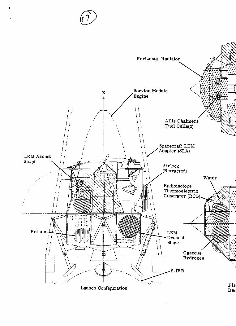
LEM AscentStage
Horizontal Radiator
Service ModuleEngine
Allis ChalmersFuel Cells(2)
Spacecraft LEMAdapter (SLA)
Airlock(Retracted)
RadioisotopeThermoelectricGenerator (RTG)
Water
LEMDescentStage
GaseousHydrogen
S-IVB
-A,Launch Configuration Pla
Deg

(II)17 A'
Pay load
Plan ViewAscent Stage
DescentPropellantTanks (4)
Airlock(Retracted)
GaseousOxygen
0 20 40 60 80 1001 , i , i , i , i , i i i , i i , i i i
Scale, in.
^" Airlock(Deployed)
^JJ
Portable LifeSupport System(2)
; Landed Configuration
Fig. 2-4 Shelter Recommended GeneralArrangement
(11)19
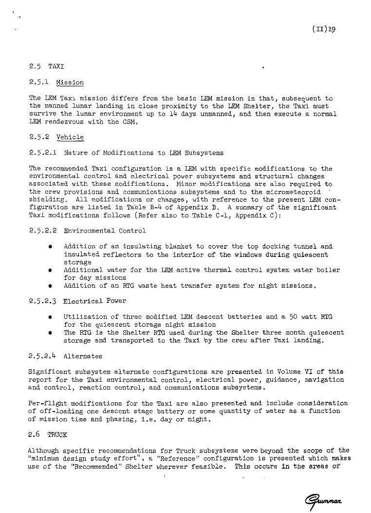
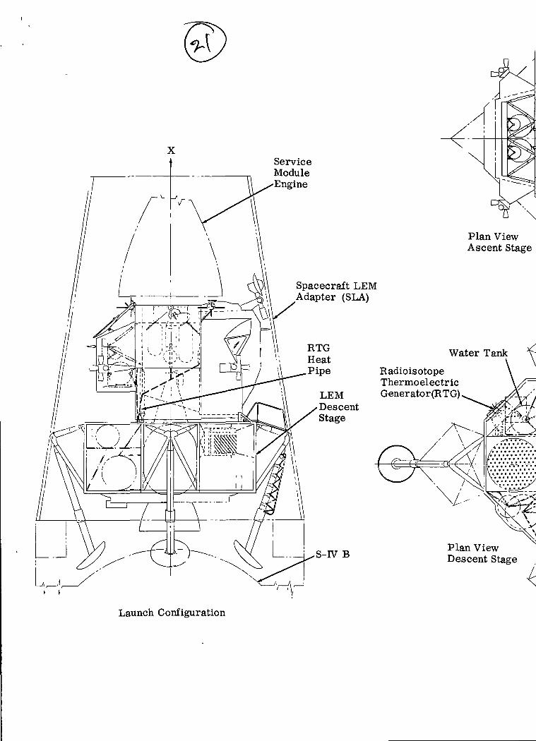
2.5 TAXI
2.5.1 Mission
The LEM Taxi mission differs from the basic LEM mission in that, subsequent tothe manned lunar landing in close proximity to the LEM Shelter, the Taxi mustsurvive the lunar environment up to lU days unmanned, and then execute a normalLEM rendezvous with the GSM.
2.5.2 Vehicle
2.5.2.1 Nature of Modifications to LEM Subsystems
The recommended Taxi configuration is a LEM with specific modifications to theenvironmental control and electrical power subsystems and structural changesassociated with these modifications. Minor modifications are also required tothe crew provisions and communications subsystems and to the micrometeoroidshielding. All modifications or changes, with reference to the present LEM con-figuration are listed in Table E-k of Appendix B. A summary of the significantTaxi modifications follows (Refer also to Table C-l, Appendix C):
2.5.2.2 Environmental Control
• Addition of an insulating blanket to cover the top docking tunnel andinsulated reflectors to the interior of the windows during quiescentstorage
• Additional water for the LEM active thermal control system water boilerfor day missions
• Addition of an RTG waste heat transfer system for night missions.
2.5.2.3 Electrical Power
• Utilization of three modified LEM descent batteries and a 50 watt RTGfor the quiescent storage night mission
• The RTG is the Shelter RTG used during the Shelter three month quiescentstorage and transported to the Taxi by the crew after Taxi landing.
2.5.2.4 Alternates
Significant subsystem alternate configurations are presented in Volume VI of thisreport for the Taxi environmental control, electrical power, guidance, navigationand control, reaction control, and communications subsystems.
Per-flight modifications for the Taxi are also presented and include considerationof off-loading one descent stage battery or some quantity of water as a functionof mission time and phasing, i.e. day or night.
2.6 TRUCK
Although specific recommendations for Truck subsystems were beyond the scope of the"minimum design study effort", a "Reference" configuration is presented which makesuse of the "Recommended" Shelter wherever feasible. This occurs in the areas of
(11)20
guidance, navigation and control, instrumentation, propulsion, communications andstructure (descent stage only). Conversely, the Environmental Control andElectrical Power Subsystem reflect the differences between the Truck and Shelter -missions. All modifications or changes with reference to the present LEM con-figuration are listed in Table B-5 of Appendix B.
ServiceModuleEngine
Plan ViewAscent Stage
'
Spacecraft LEMAdapter (SLA)
RTGHeatPipe
Water Tank
LEMDescentStage
RadioisotopeThermoelectricGenerator(RTG)
. ^S-IV B Plan ViewDescent Stage
LV \
Launch Configuration

Reaction Control SubsystemJet Cluster
DescentPropellantTanks (4)
0 20 40 60 80 100i i • •

Landed Configuration
Fig. 2-5 Taxi RecommendedGeneral Arrangement

(11)23/24
3. MANAGEMENT PLAN
3.1 ORGANIZATION
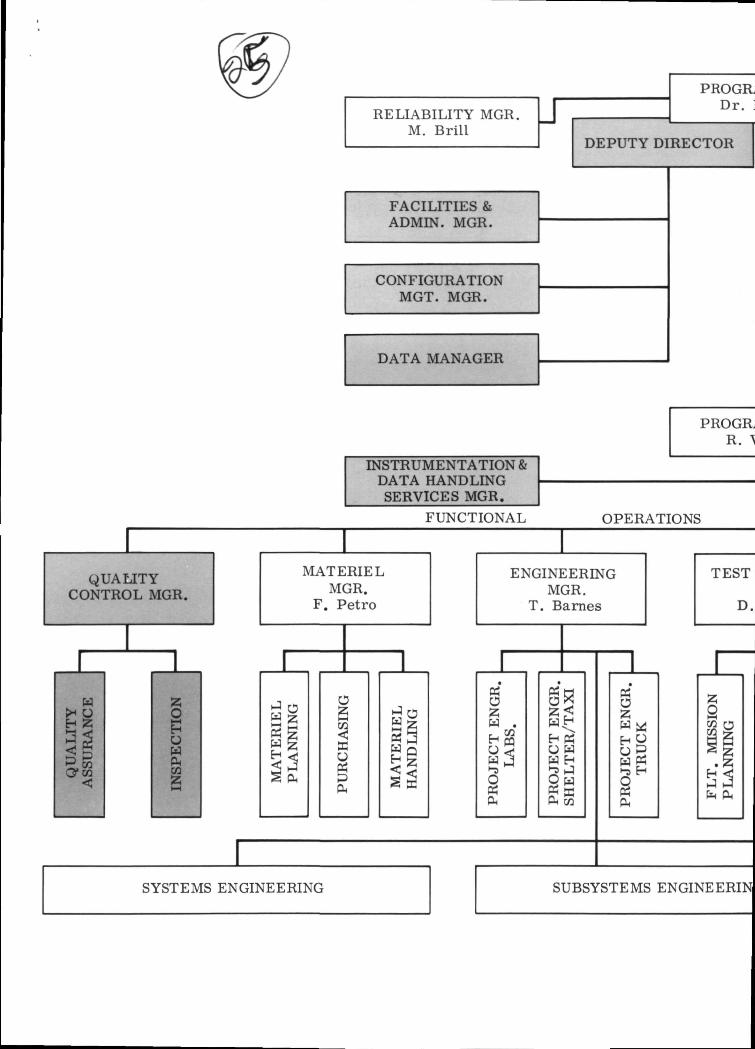
The AES/LEM Program will be managed by an organization designed specifically tomeet the special requirements of this program. (See Fig. 3-1)- Dr. R. H. Tripp•will head the organization as Program Director. He will report to Grumman Pres-ident E. Clinton Towl, from whom he derives the authority to command all re-sources required for the program.
The organization consists of key managers who will be accountable for planningand meeting the costs, schedules, and performance goals which will collectivelyassure the meeting of overall AES Program objectives. The functions they willmanage have been carefully defined to prevent duplication of effort and to pro-mote clear understanding of accountability. For example, each subsystem willbe handled both within the Grumman Company and at the subcontractor's plant bya Subsystem Manager who will be accountable for all aspects of the managementof his subsystem until it is installed in a vehicle. There will be a vehiclemanager for each vehicle from inception to launch. Continuing top managementguidance and participation will be accomplished through the Executive andTechnical Review Board.
Studies of the proposed organization will continue during the Definition Phase.As a result of these studies and discussions with NASA, the organization for theDevelopment/Operations Phase will be finalized.
The work task requirements for the AES Program dictate the need for people withhigh technical competence and space technology experience. Grumman can meet thisneed with people who will become available from the LEM, OAO and other Companyprograms. This will be done without interference to these programs and willprovide people who have experience in design, development, fabrication and testof space hardware and vehicles.
3.2 PLANS & CONTROLS
Plans required for the Definition and Development/Operations Phases are presentedand discussed in the various volumes of this report. They include the followingareas:
Design and DevelopmentProcurementTest and Site OperationsManufacturingPERT IntegrationManpowerFacilities
Configuration ManagementQualityReliabilityMaintenanceSupportTrainingTransportation
These plans to be defined in detail throughout the Definition Phase, will be thebasis of controlling all program parameters.
&XumnuuL
RELIABILITY MGR.M. Brill
PROGRDr.
DEPUTY DIRECTOR
FACILITIES &ADMIN. MGR.
CONFIGURATIONMGT. MGR.
DATA MANAGER
INSTRUMENTATION &DATA HANDLINGSERVICES MGR.
PROGR.R.
FUNCTIONAL OPERATIONS
QUALITYCONTROL MGR.
1
[Q
UA
LIT
YA
SS
UR
AN
CE
INS
PE
CT
ION
SYSTEMS
MATERIELMGR.
F. Petro
1
MA
TE
RIE
LP
LA
NN
ING
1
PU
RC
HA
SIN
G
MA
TE
RIE
LH
AN
DL
ING
rENGINEERING
ENGINEERINGMGR.
T. Barnes
I
PR
OJE
CT
EN
GR
.L
AB
S.
PR
OJE
CT
EN
GR
.S
HE
LT
ER
/TA
XI
PR
OJE
CT
EN
GR
.T
RU
CK
TEST
D.
rF
LT
. M
ISSI
ON
PL
AN
NIN
G
^—
SUBSYSTEMS ENGINE ERIN

I DIRECTORH. Tripp
EXECUTIVE &TECHNICAL
REVIEW BOARD
CONTRACTS MGRE. Deinard
PROG. PLAN &CONTROL MGR.
J. Rosse
VI MANAGERBenito
- ASST. PROG. MGR.
MANAGERS
SITE OPS.MGR.loltje
1H
rifi
HT
F
AU
ILdT
AC
TIV
AT
ION
TE
ST
OP
ER
AT
ION
S
SUPPORT
C. R.
IHPH
IOU
ND
SU
PP
OE
NG
INE
ER
ING
o
MGR.Spinner
1
LO
GIS
TIC
S
MAI
J.
ro!Z
AN
UFA
CT
UR
I]IT
MnT
Min
r'nT'
Nm
%
\TEST ENGINEERING
2

(11)25
Note: Shaded Boxes Designate Activities WhichWill Be Staffed & Phased-in During theDefinition Phase
_,LJFAC TURING
MGR.Jierschenk
OH0PPO3
SUB-SYSTEM
MGRSVEHICLE
MGRS.
VEHICLE DESIGN ENGINEERING
Fig. 3-1 Grumman AES/LEM ProgramOrganization

(11)27
4. SCHEDULES
k.l AES/LEM SUMMARY SCHEDULE
The AES/LEM Summary Schedule shown in Fig. h-1 presents the basic program for eachof the four vehicles in relation to the LEM launch schedule. (The schedules arebased upon the Flight Mission Assignment Plan for AES Planning, ML-65-1 dated 7August 1965, and the LEM Program Schedule III Revision 1, dated 7 September 1965.)
In accordance with NASA guidelines, the Phase I Laboratory vehicles will be fab-ricated and assembled to the LEM configuration at Grumman; subsequently, they willbe modified to each particular laboratory flight configuration at KSC. The Phase ILab missions currently planned include Earth orbit rendezvous, Earth polar orbit,Earth synchronous orbit, and lunar orbit flights. Saturn IB and Saturn V launchvehicles will be used. As shown on the schedule, these launches will occur duringthe time span of the last four LEM launches.
The Phase II Laboratories will be fabricated and assembled at Grumman using a modi-fied LEM manufacturing cycle. Their missions will be similar to those of the PhaseI Laboratories except that mission durations will be up to It-5 days instead of l.k,and the experiments conducted will be progressively more comprehensive. All Lab-oratory missions will be manned. Some of the missions will be launched by theSaturn IB, the others will use the Saturn V launch vehicle.
The Shelter and Taxi vehicles, also fabricated and assembled at Grumman, will beused for extended-stay lunar exploration missions. These missions, along with thePhase II Lab missions, will take place in the two-year time period following thebasic LEM and Phase I Lab missions. The Shelter will be landed unmanned on thelunar surface and be capable of 90-day storage prior to use as the base of operationsfor the two-man team during their lit--day stay. The Taxi, which will separate fromthe CSM in lunar orbit, will land the two-man team on the Moon and, after a l^-dayquiescent storage period during the operations from the Shelter, the Taxi's ascentstage will return them to the CSM, and thence to Earth. Shelters and Taxis willbe launched by the Saturn V.
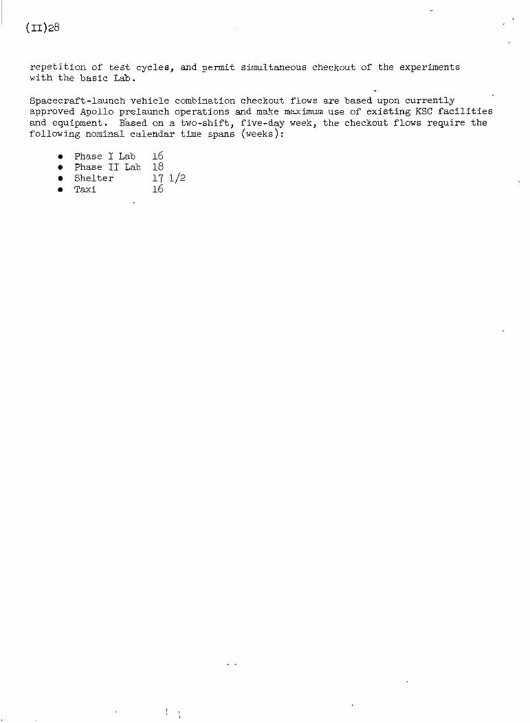
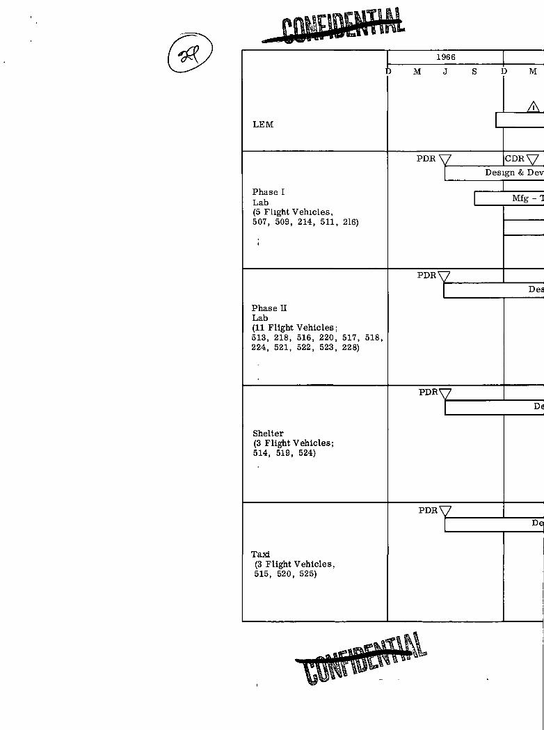
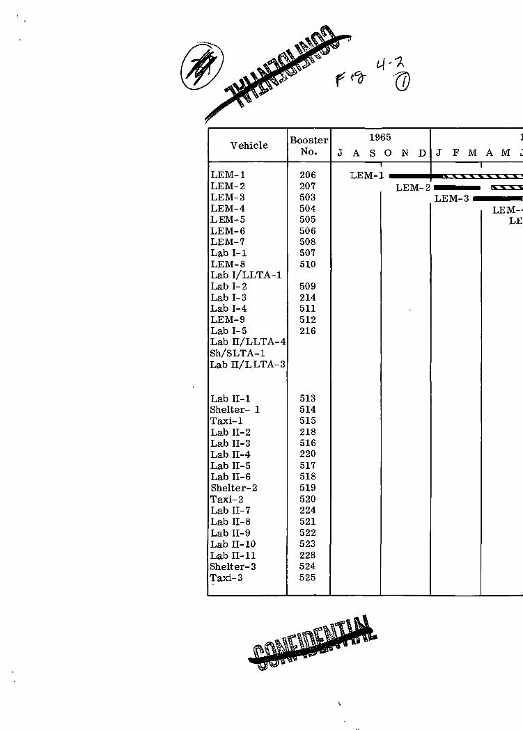
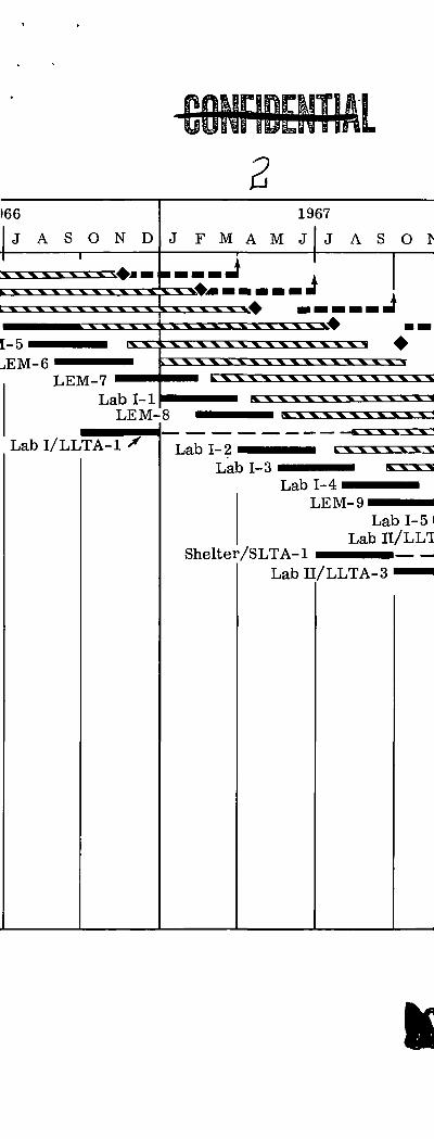
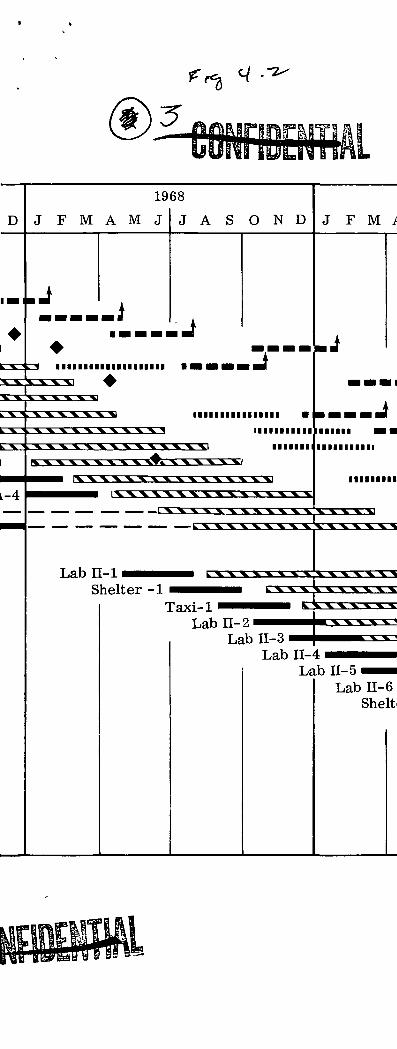
U.2 AES AND BASIC LEM VEHICLE SCHEDULE
A composite manufacturing, prelaunch, mission operations schedule for all LEM andAES vehicles is shown in Fig. k-2. It indicates the phasing required to integratethe AES spacecraft into the presently planned Manned Lunar Landing Program withoutimpairing the LEM schedule. It should be noted that the start of manufacturingafter LEM k is advanced to accommodate the Phase I Lab modifications and the testarticle development, within the launch-date and final-assembly facility availabilityconstraints. This is additionally advantageous in that it permits a constantdelivery rate for efficient manpower/facility utilization.
Phase II Laboratory experiments are assumed to be installed on the assembly linein parallel with installation of the Lab primary systems and subsystems. Thisprocedure will reduce the number of stations in the operational flow, preclude
(11)28
repetition of test cycles, and permit simultaneous checkout of the experimentswith the basic Lab.
Spacecraft-launch vehicle combination checkout flows are based upon currentlyapproved Apollo prelaunch operations and make maximum use of existing KSC facilitiesand equipment. Based on a two-shift, five-day week, the checkout flows require thefollowing nominal calendar time spans (weeks):
• Phase I Lab 16• Phase II Lab 18• Shelter 17 1/2• Taxi 16
D
LEM
Phase ILab(5 Flight Vehicles,507, 509, 214, 511, 216)
Phase IILab(11 Flight Vehicles;513, 218, 516, 220, 517, 518,224, 521, 522, 523, 228)
Shelter(3 Flight Vehicles;514, 519, 524)
Taxi(3 Flight Vehicles,515, 520, 525)
1966
M D M
PDR
I Design & Dev
IMfg - 1
Dea
I De
PDRW

(11)29/10-
1967 , 1968 1969 1970 1971
J S D M J S D M J S ' D M
'l\ /1X 2,Prelaunch Operations
lopment
est Articles
oJlfg. Fit Vehicles at Grumman & Modify at KSC
A A APrelaunch Operations
gn & Development
Mfg - Test Articles
S D M J SI
Legend
^7 Design Milestone
PDR- Preliminary Design Review
CDR- Critical Design Review
<0: First Vehicle Assembled & Tested
/\ Launch
A Earth Orbit
A Earth Polar Orbit
Zl\ Earth Synchronous Orbit
/4\ Earth Orbit - Rendezvous
Lunar Mission
D
Manufacture Flight Vehicles
AAA® A AAPrelaunch Operations
sign & Development
Mfg - Test Articles
O ;
Manufacture Flight Vehicles
Prelaunch Operations
sign & Development
| Mfg - Test Articles
Manufacture Flight Vehicles
Prelaunch Operations
Fig. 4-1. AES/LEM Schedule Summary
^Skunman.
Vehicle
LEM 1LEM-2LEM- 3LEM-4LEM-5LEM- 6LEM- 7Lab 1-1LEM- 8Lab I/LLTA-1Lab 1-2Lab 1-3Lab 1-4LEM- 9Lab 1-5Lab H/LLTA-4Sh/SLTA-1Lab H/LLTA-3
Lab II- 1Shelter- 1Taxi-1Lab II- 2Lab II- 3Lab II-4Lab II- 5Lab II- 6Shelter- 2Taxi- 2Lab II-7Lab II- 8Lab II- 9Lab 11-10Lab 11-11Shelter- 3Taxi- 3
BoosterNo.
206207503504505506508507510
509214511512216
513514515218516220517518519520224521522523228524525
1965
J A S O N Di
LEM-2
]
J F M A M :I
^_^_ i^^LEM- 3 ^^^MH
LEM-'LE
166
J A S O N D
1967
J F M A M J J A S O 1 S
Jt...
1-5 ^.•^.•'^•^.•^.•^.•^.•^.•^.•^.•^.•^.•^.^.•^^.•^.•'q^.^^.^.^.^.•^.•^•^.•^.•^
LEM-7Lab 1-1
LEM-8
Lab I/LLT! ^^ Lab 1-2
Lai
Shelter
bI-3— •Lab
I
•/SLTA-1Lab II
Lab 1-5 iLab II/LL1
/LLTA-3
D
1968
J F M A M J J A S O N D J F M
Illlllllllllllllllll
.....J7
I•^ ^ ^ ^ ^ "^fc- . . . •%! Illlllllllllllll •
% . ^ . ^ . V V V V V X . V ^ Illllllllll
X.%.^.X.VVVVVX.X.^ .X.VI Illllll
^•^^•^•^•^•^•^•^ ^y>. -^ •^ •%. ^ ^/
,...JIllllll .1
Illllllllll
Illllllll
Lab H-lShelter -1 c~v ^.•^.V^.'^.^.-^.-^.-^,
Lab II-2 iLab H-3
Lab II-4
Lab n-6iShelti

1969
M J J A S O N D
1970
J F M A M J J A S
Lab II-10 iLab 11-11
Shelter-3Taxi-3_j

IDENTIAL (11)3:
O N D
19
J F M A M J
71
J A S O N D
Structural AssemblyFinal Assembly & Test
mi Modification,Installation & Checkout at KSC
• • Prelaunch Checkout at KSC
— Structural & Environmental TestsOriginal Shipping Date (LEM Schedule III)Launch Date
...1• ••MM
szs >m\• ' »...LJ^ ^ ^ "^
..J
i
..JLV»^ •.1m m m l
Fig. 4-2 Proposed LEM & AESIntegrated Schedule

(11)33
5. TEST REQUIREMENTS
5.1 GROUND DEVELOPMENT TESTING
5.1.1 Objectives
Ground development testing is concerned with events accomplished during design anddevelopment, system verification/demonstration, and flight spacecraft fabricationand acceptance. Design and development requires defining the structural, mechanical,thermal, electrical, and data management interfaces. System verification/demon-stration is concerned with the structural dynamic response of the baseline vehicleand the verification or demonstration of experimental payload and spacecraft inte-gration under ambient and induced environmental conditions. The flight spacecraftfabrication and acceptance identifies the procedures used for installation andacceptance testing of the integrated flight configuration.
Objectives of the AES/LEM development test articles are to verify:
Subsystem and systems integration of the basic vehicleFunctional integrity of the basic vehicleBasic vehicle subsystems under environmental conditionsDesign changes by testingGround support equipment functional interface with the basic vehicleOperational checkout procedures generated to check out the basic vehicleElectromagnetic compatibility within the basic vehicles and between thebasic vehicle subsystems and the external equipment
• Reliability analysis and predictions
5.1.2 Major Test Articles
The following is a summary of the required major test articles:
PHASE I LAB
LM-1
LLTA-1
Wood-and-metal mockup fabricated in Phaseto reflect current configuration.
"C" and further updated
LLTA-2
Complete Ascent/Decent Stages structurally and thermally func-tional and representative of the Lab Configuration. Cabinleakage integrity must be maintained. Subsystems will bestructurally and thermally representative of qualified equip-ment .
LEM LTA-8 modified to the Phase I Lab Configuration for use atMSC.
(~£AAvnmajL
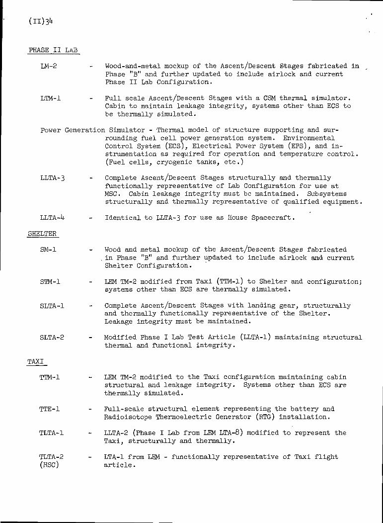
PHASE II LAB
LM-2
LTM-1
Wood-and-metal mockup of the Ascent/Descent Stages fabricated inPhasePhase II Lab Configuration.
"B" and further updated to include airlock and current
Full scale Ascent/Descent Stages with a CSM thermal simulator.Cabin to maintain leakage integrity, systems other than ECS tobe thermally simulated.
Power Generation Simulator - Thermal model of structure supporting and sur-rounding fuel cell power generation system. EnvironmentalControl System (ECS), Electrical Power System (EPS), and in-strumentation as required for operation and temperature control.(Fuel cells, cryogenic tanks, etc.)
LLTA-3
LLTA-4
SHELTER
SM-1
STM-1
SLTA-1
SLTA-2
TAXI
TTM-1
TTE-1
TLTA-1
TLTA-2(HSC)
Complete Ascent/Descent Stages structurally and thermallyfunctionally representative of Lab Configuration for use atMSC. Cabin leakage integrity must be maintained. Subsystemsstructurally and thermally representative of qualified equipment,
Identical to LLTA-3 for use as House Spacecraft.
Wood and metal mockup of the Ascent/Descent Stages fabricatedin PhaseShelter Configuration
"B" and further updated to include airlock and current
LEM TM-2 modified from Taxi (TTM-1) to Shelter and configuration;systems other than ECS are thermally simulated.
Complete Ascent/Descent Stages with landing gear, structurallyand thermally functionally representative of the Shelter.Leakage integrity must be maintained.
Modified Phase I Lab Test Article (LLTA-l) maintaining structuralthermal and functional integrity.
LEM TM-2 modified to the Taxi configuration maintaining cabinstructural and leakage integrity. Systems other than ECS arethermally simulated.
Full-scale structural element representing the battery andRadioisotope Thermoelectric Generator (RTG) installation.
LLTA-2 (Phase I Lab from LEM LTA-8) modified to represent theTaxi, structurally and thermally.
LTA-1 from LEM - functionally representative of Taxi flightarticle.

(11)35/36
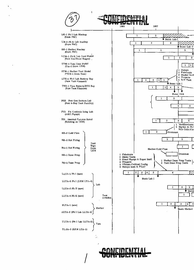
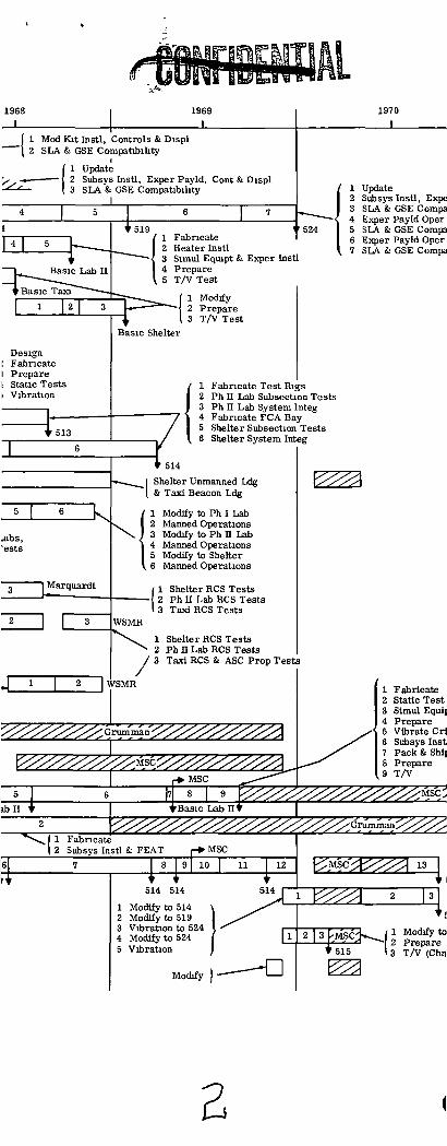
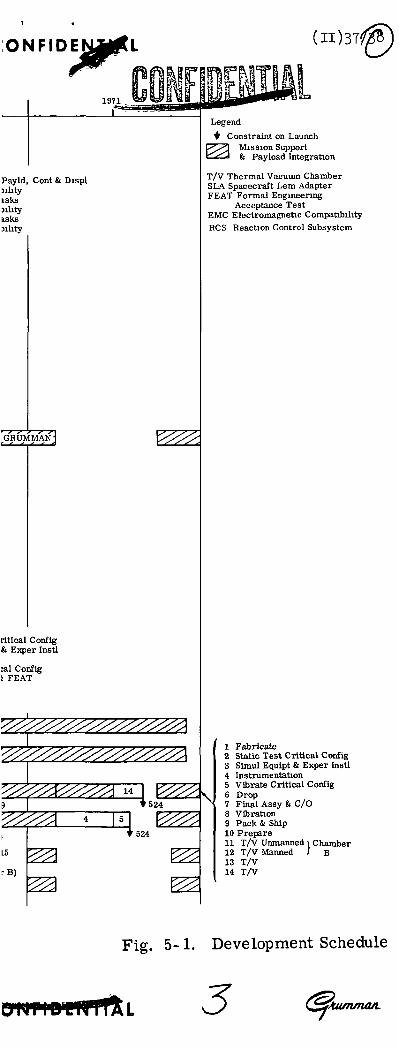
The development schedule presented in Fig. 5-1 indicates tasks necessary to verifythe design and demonstrate the capability of the four basic spacecraft. It coversthe utilization of the test articles listed above and highlights their use formore than one basic configuration.
5.2 FLIGHT TESTING
The prime purpose of the AES missions is to conduct extensive experiments for basicscientific research, develop and qualify new systems and subsystems, show space-craft and crew capability to withstand long duration missions, and develop spaceoperating procedures and techniques. The planned number of AES-LEM flight missionscan be categorized as follows:
LAUNCH VEHICLEAES-LEM Saturn IB Saturn V
Phase I Lab 2 3Phase II Lab k 7Shelter 3Taxi 3
Since each type of AES-LEM is scheduled for a number of flight missions, the space-craft test objectives must be satisfied as early as practicable. Instead of per-forming special flight development missions, the AES program will utilize theprerequisite Apollo program flight development in conjunction with a comprehensiveAES Ground Development Test Program to relieve AES test constraints. However,flight test objectives will be integrated within the flight operations of theinitial flight of each AES/LEM mission combination. The chief requirements forthis are:
• To demonstrate system performance for environmental conditions notattainable to a satisfactory degree on the ground
• To assure subsequent mission success of each similar baseline AES/LEMvehicle
• To assure maintaining the high-density launch schedule.
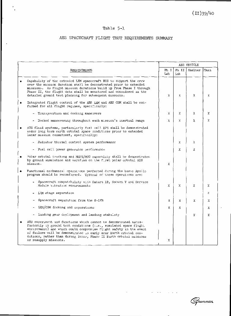
Table 5-1 summarizes the flight test requirements associated with each of theAES-LEM spacecraft. These requirements are further defined in terms of testobjectives for each type of AES-LEM/mission combination in Vol. XVI, Prelaunchand Mission Operations. As the scientific mission objectives are further defined,the flight test requirements will be reviewed and considered in the light of thetotal flight mission requirements.
> f
1LM-1 Ph I Lab Mockup
(from PhC)
LM-2 Ph U Lab Mockup(from PhC)
SM-1 Shelter Mockup(from PhC)
LTM-1 Ph II Lab Test Model(New Aso/Desc Stages) ,
TTM-1 Taxi Test Model(Tm-2 from LEM)
STM-1 Shelter Test Model(TTM-1 from Taxi)
LTE-1 Ph I Lab Battery Bay(New Test Element)
TTE-1 Taxi Battery/fcTG Bay(New Test Element)
PCS Pwr Gen Section Lab(New 4-Bay Test Facility)
FCI Fit Controls Integ Lab(Add'l Equipt)
IBS Internal Environ Simul(Existing on LEM)
HR-2 Cold Flow N
KR-3 Hot FiringTestRigs
PA-1 Hot Firing > fromLEM
HD-1 Desc Prop
PD-1 Desc Prop J
LLTA-1 Ph I (new) N
LLTA-2 Ph I (LEM LTA-8)> Lab
LLTA-3 Ph II (new)
LLTA-4 Ph II (new) J Test' Articles
SLTA-1 (new) ^1S Shelter
SLTA-2 (Ph I Lab LLTA-1)")
TLTA-1 (Ph I Lab LLTA-2)]S Taxi
TLfA-2 (LEM LTA-1) J
1966 19671
1 i 1 2 vmtmsss—^ Basic Lab I
1 | 2 3
1 Fabricate2 Static Test3 Simul Equ4 Prepare5 Vibrate Ci6 Subsys Ins
1 1
i
1 |
^^^^' Basic Lab n
3 1i
1 | 2 | 3
\1 | 2 | 3 4| 5 f (
1 i h1 Design2 Fabricate3 Heater Inst4 Prepare5 T/VTest
i Basic Lab I
i i i hi 4 i 5 r-~— .Basic
{,
n*Taxi
1 1 1 2 1
,| 4 | 5
| 1 | 2 | 3 | 4
/(*1 1 1 2 [Grumman
ModificationsShelter & PhRCS Cold Flo
1 2
Shelter Cold Flow L
& 1pt&Experlnstl 1 1 sheltert)esc
•itlcal Config \2TaxiDescPitl & FEAT / N.
^D [
3rumman
Prop Tests |op Tests (
21 3 |4| 5 1 6 &
1 1Basic Lab I
1 1 2 J 3
t Basi
1 1 1 ^ 1 3 |4| 5
* Sasic Shelter
1968 1969
( 1 Mod Kit Instl, Controls & Displ1 2 SLA & GSE Compatibility
{ 1 Update2 Subsys Instl, Exper Payld, Cont Si Displ3 SLA & GSE Compatibility
4 | 5 | 6 | 7
*l * L__
L^^ Basic Lab II
T Basic Taxi~~ • —
+ 519 '11 Fabricate
2 Heater Instl3 Simul Equipt & Exper Inst4 Prepare5 T/V Test
' 1 1 Mnriifv
I | 2 | 3 [— -:=*- { 2 Prepare
DesignFabricatePrepareStatic TestsVibration
1
T 513
^ 1 3 T/V TestBasic Shelter
(1 Fabricate Test Ri2 Ph II Lab Subsecti3 Ph H Lab System 1
5 Shelter Subsection6 Shelter System Int
1970
1 Update2 Subsys Instl, Expe3 SLA Si GSE Compa4 Exper Payld Oper
1 524 5 SLA Si GSE Compa6 Exper Payld Oper7 SLA & GSE Compa
?son TestsntegyTests
eei ° r
H e kl
'ests
""3" I Marquardt
- — i r^rn
J 1 2 |V
i 514
• •^^ f Shelter Unmanned Ldg( St Taxi Beacon Ldg
(1 Modify to Ph I Lab
\2 Manned Operations3 Modify to Ph D Lab4 Manned Operations5 Modify to Shelter6 Manned Operations
I 1 Shelter RCS Tests1 2 Ph II Lab RCS TealsI 3 Taxi RCS Tests
WSMR
^X. 1 Shelter RCS Tests^ 2 Ph n Lab RCS Tests
J 3 Taxi RCS Si ASC Prop Test
rSMR
^x^>/^><^> Grumman^>x^>X^>^^^>|
](<^^^^^^^^^^^r>MSC _ --'"
9
1 Fabricate2 Static Test3 Simul Equi]4 Prepare
^ 5 Vibrate Cr]^ — 6 Subsys Inst
.s' 1 Pack Si Shi]^- — 8 Prepare
^9 T/V
5 1 6 |7| 8 9 F^x/' x ' x-^^X^^^abll 1
2+ Basic Lab nt
^^x:x^::'//<x^^'*x^ 1 Fabricate2 Subsys Instl Si FEAT r-* MSC
6| 7 | 8 | 9 1 10 | 11 | 12
1 * * +
k/MSC^^/>q 13 |
i514 514 614 J Vs^/Z/A 2 1 3 1
1 Modify to t>14 \ ^*2 Modify to 519 1 .^
4 Modify to 524 | 15 Vibration )
Modify } — ' — 1
*i
2 | 3 p.MSC^*^_| Coolly to
isis Is T/vr(Chn
(11)37
Payld, Cent & Displnhtyiskssilityisksaility
rttlcal Conflg& Exper Instl
:al Conflgi FEAT
L5
r B )
Legend
f Constraint on Launchu^/n Mission Supportr^3 & Payload Integration
T/V Thermal Vacuum ChamberSLA Spacecraft Lem AdapterFEAT Formal Engineering
Acceptance TestEMC Electromagnetic CompatibilityRCS Reaction Control Subsystem
\
1 Fabricate2 Static Test Critical Conflg3 Slmul Equipt & Exper Instl4 Instrumentation5 Vibrate Critical Config6 Drop7 Final Assy & C/O8 Vibration9 Pack & Ship10 Prepare11 T/V Unmanned i Chamber12 T/V Manned / B13 T/V14 T/V
Fig. 5-1. Development Schedule
5
(II)39AO
Table 5-1
AES SPACECRAFT FLIGHT TEST REQUIREMENTS SUMMARY
REQUIREMENTS
• Capability of the extended LEM spacecraft ECS to support the crewover the mission duration shall be demonstrated prior to extendedmissions. As flight mission durations build up from Phase I throughPhase II, the flight data shall be monitored and considered in thedetailed ground test planning for subsequent missions.
• Integrated flight control of the AES LEM and AES CSM shall be con-firmed for all flight regimes, specifically:
Transposition and docking maneuvers
- Docked maneuvering throughout each mission's inertia! range
• AES fluid systems , particularly fuel cell EPS shall be demonstratedunder long term earth orbital space conditions prior to extendedlunar mission commitment, specifically:
Eadiator thermal control system performance
- Fuel cell power generator performance
• Polar orbital tracking and MSFN/MCC capability shall be demonstratedby ground simulation and verified on the first polar orbital AESmission.
• Functional mechanical operations perfected during the basic Apolloprogram should be reconfirmed. Typical of these operations are:
- Spacecraft compatibility with Saturn IB, Saturn V and ServiceModule vibration environments
- LEM stage separation
- Spacecraft separation from the S-1VB
- LEM/CSM docking and separations
- Landing gear deployment and landing stability
• AES experiment and functions which cannot be demonstrated satis-factorily in ground test conditions (i.e., simulated space flightenvironment) and which could compromise flight safety in the eventof failure will be demonstrated in early near Earth orbital con-ditions, rather than during lunar, Phase II Earth orbital missionsor resupply missions.
AES VEHICLE
Ph ILab
X
X
X
X
X
X
X
X
Ph IILab
X
X
X
X
X
X
X
X
Shelter
X
X
X
X
X
X
X
X
Taxi
X
X
X
X
X
X
X
X
Vuvnman.
6. FACILITIES
6.1 INTRODUCTION
The AES Program, as presently planned, takes fullest advantage of the currentApollo/LEM facilities on a non-interference basis. Because of the proposed vehiclemodifications and increased production rate, some existing facilities will have tobe modified and new ones added. These facilities include manufacturing and testfacilities at Grumman and government facilities at Kennedy Spacecraft Center (KSC),Manned Spacecraft Center (MSC) and the White Sands Test Facility (WSTF). They donot include those for the Manned Spacecraft Flight Network (MSFN) or other opera-tional facilities after vehicle launch.
6.2 GRUMMAN MANUFACTURING FACILITIES
The facilities planning performed during Phase B indicates that existing and plannedLEM manufacturing facilities will satisfy the major needs for the manufacture andassembly of up to eight AES vehicles a year at Grumman. Fig. 6-1 is a recent photoof the LEM final assembly area, which will be similarly utilized for AES vehicles.
Additional facilities requirements are limited to accommodation space and a thirdAcceptance Checkout Equipment-Spacecraft (ACE-S/C) facility consisting of a com-puter and control room and assumed to be provided as Government Furnished Equip-ment (GFE). Fig. 6-2 shows a LEM Acceptance Checkout Facility.
6.3 GRUMMAN TEST FACILITIES
Existing or planned LEM test facilities at Grumman will be fully utilized for AES.New facilities or major modifications to existing facilities indicated by the PhaseB study are:
• A Power Generation System (PGS) Test Facility to support fuel cell andreactant tankage development and integration testing
• An additional test room for concurrent Phase II Lab, Shelter and TaxiElectrical Power System (EPS) development, subsystems integration andpower distribution (PDS) breadboarding.
6.U GOVERNMENT FACILITIES
Government facilities utilization will be required at KSC, MSC, and WSTF. With fewexceptions, existing facilities at these locations are capable of supporting theAES Program activities without major changes. Those additional facilities requiredare needed primarily to support the modification of LEM vehicles to the AES Phase ILab configuration, and to accommodate the increased launch density planned for theAES vehicles. The required additional facilities are:
• Space at KSC for the modification activities associated with the Phase ILaboratories

(H)te
A vibration shaker system with sine and random capabilities to permitvibration testing at KSC after vehicle modificationsTwo additional ACE station installations to support the modification andprelaunch checkout operations of the AES/LEM vehiclesProvisions for the support of mission training simulation and an InternalEnvironment Simulator for flight crew training.
Fig. 6-1 LEM Final Assembly Area
Fig. 6-2 Acceptance Checkout Facility
7. SUPPORT
7.1 SCOPE
The AES Support Program will provide the definition, integration, and delivery ofground support equipment and publications during the development manufacturing,checkout, launch, and post-launch phases of the AES Lab I, Lab II, Shelter, andTaxi vehicles. The program is planned as a continuation of the LEM support effortalong a parallel path with somewhat expanded objectives. Applicable LEM supportelements and program plans will be continually monitored to ensure concurrent com-patibility between the two programs relative to AES items which are dependent uponthe LEM Program.
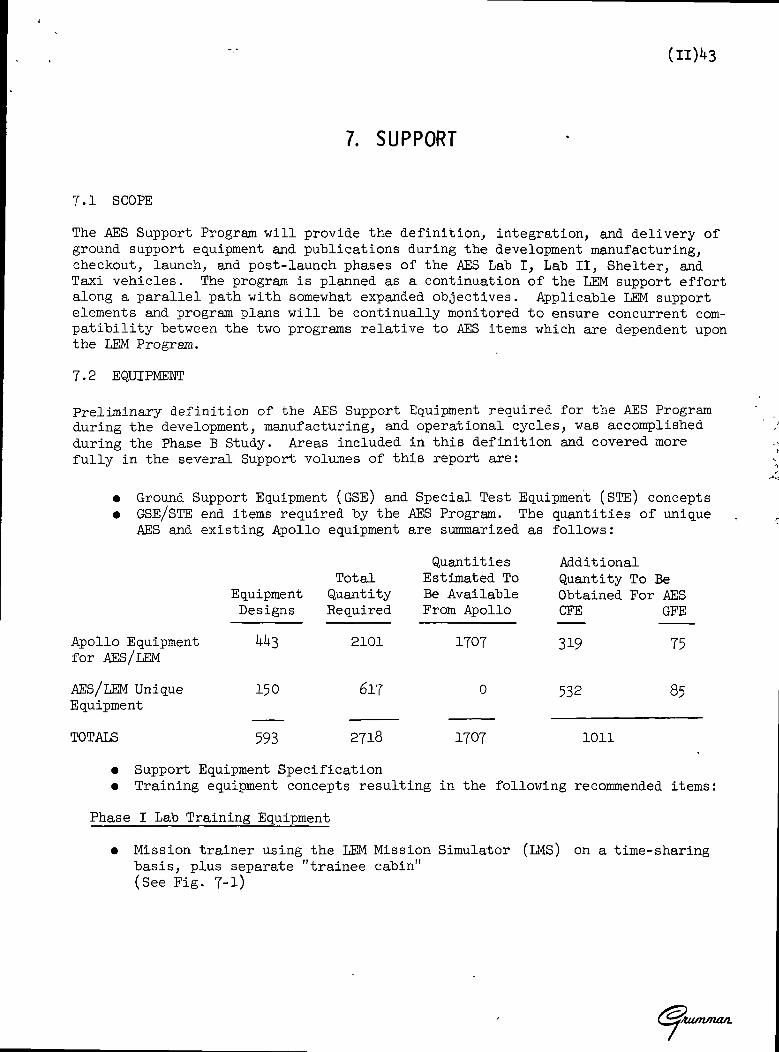
7.2 EQUIPMEM1
Preliminary definition of the AES Support Equipment required for the AES Programduring the development, manufacturing, and operational cycles, was accomplishedduring the Phase B Study. Areas included in this definition and covered morefully in the several Support volumes of this report are:
• Ground Support Equipment (GSE) and Special Test Equipment (STE) concepts• GSE/STE end items required by the AES Program. The quantities of unique
AES and existing Apollo equipment are summarized as follows:
Apollo Equipmentfor AES/LEM
AES/LEM UniqueEquipment
TOTALS
EquipmentDesigns
Ul+3
150
TotalQuantityRequired
2101
617
QuantitiesEstimated ToBe AvailableFrom Apollo
1707
AdditionalQuantity To BeObtained For AESCFE GFE
319
532
75
85
593 2718 1707 1011
• Support Equipment Specification• Training equipment concepts resulting in the following recommended items;
Phase I Lab Training Equipment
• Mission trainer using the LEM Mission Simulator (IMS) on a time-sharingbasis, plus separate "trainee cabin"(See Fig. 7-1)
(11)44
• System Trainers
- Integrated Flight Control System (IFCS)- Environmental Control System (ECS)- Electric Power System (EPS), Batteries- Sequential Flow System
• Familiarization Trainers
Phase II Lab Training Equipment
• Lab Mission Trainer• Internal Environment Simulator (IES). Trainer
- • System TrainersfT
- IFCS (Phase I trainer modified)- ECS (Phase I trainer modified)- Electric Power System (EPS), Fuel Cells- Sequential Flow System (Phase I trainer modified)
• Familiarization trainers (Phase I trainers modified)
Shelter Training Equipment
• Operational Procedures Trainer (OPT)• System trainers
- Electric Power System (EPS), RTG V- ECS(Phase II Lab trainer modified)- Sequential (Phase II Lab trainer modified)
• Familiarization Trainers (Phase II Lab trainers modified)
Taxi Training Equipment
• LEM Mission Simulator (Modified) <
7-3 PLANNING
Preliminary analyses and studies were performed, and plans and schedules formulatedfor the AES Support Program, including:
• A Training Plan for identifying the general requirements, objectives,course data, training equipment, and facilities
• A Support Manual Program with the criteria and methods for its establish-ment, implementation, and maintenance
• The Maintenance Analysis effort, and the procedures and documentation in-volved in its application
• A Material Support Plan for insuring spare hardware availability in supportof the development and operation of vehicles and Ground Support Equipment(Spare hardware includes two sets of "black box" spares plus the equivalentof one set in bit-and-piece parts.)
• The Basic Transportation Policy, which will be essentially the same as thatdeveloped for the LEM Program, will be to use air transportation as the basicmode for moving flight articles and major test articles to and from Grumman.Fig. 7-2 indicates a typical mode utilizing the B-377 P.G. Aircraft.

I•r-C
o
CO
§2wJ•8co
01CJcoOto
en
w

SHOJH
• rH
<
d
C-C-eo
i
g,
CM
t-
bb

ooCO
CO
COUJ
O
CO
CO
UJQ_Q_
to£_,cdgS
PH
-P 08•H CQ
nd H CQ FHCO -H CU 0O XI M -PH 03 ft>> ft •» C8 CQCO CO X! jgj H
0CO
0 O£3 PH«(-! pM H
PH PH
§•H•p
CO CQ
p -a
HOC
,_j ,_J ^^^
Xi Q -p bQFH • r-j 0O fl <! tJ
ti•H
Coo
-p •H O
HCOO•H
0
Q
•HPH
^-P0HHCO
PH
sCQ
1
,
fO0
EH
CQ
O r"SM
• O-P HH OPm fl
_-j-
H
OON
WooCM
SCQO
HHOJ
^
CU-pCQ
CQ
j>5Q)> HFH COd o
CQ vH
FH 0cO 83 -H
0ooCOON
MC !>5-P•H 0 dCQ > Od FH AJ0 S O
CQ CQ 0
•P 3
cd 3 £*iH ^ CO
j-H
OON
W
Q
OJ
1~*g-CQO
Is-0
cOo•H
0So•HPH >3
^ 0-P CJ0 OH FHrH -P
CO COPH ^
8cn
•s,o
feg
co-pUJ
_^-H
O
pf"|
OLj"\ooONH
1^CQO
ONQ
LTN
_-j-
r-\X! OJOa ad 0cO 0
-pS 0S X>a
CQrti d0 Ofl >3 0
TO f^Ci (U
tOPH
8* *
oo
1 11 1
1 -H/
1 H
• •
CO COOJ OJ
O 0o oOJ OJ
S SH CQa o
-^~ Lf\H HOJ OJ
^S0-pCQj>^
CQ
r**0
JH
^jCQ
LTN FHrH COCM g08 I-H
O0OJ
o
08r^0
2
CQ
c3Hp
^-H
J5
r^"• ^
[ "]
OCO
1^CQU
HHLT\
Or*2cti
SM
i — ! hHcOO T3•H 0
0 2
Q C3
•H SPH tD
*
Mfl I
•H 1
ftcOS
11
LTN•
COOJ
"H"ooOJ
2Fya
voOJ
^orHOJ
a00Is-p0
CQjjO
^
0 C—^ i — IC OJ0K 08
OOCO
r-TOO
,
1
-4-H
LT\•
COOJ
O0OJ
g.CQ^
t—HOJ
iO
o *\CO
^ arH 0CO -HFH -PO cO•H >^ ?H03 CU& CQ(L> ,0 ^pp o bC
o•xrH H• CO O
TJ O FH0 -H OS CQ 00 >» -p•H Xl 0W ftS
0o0
06"ON
0-P CQc a0 O•H -HFH -P
O cOo
Xl «H-P HFH ft03 ft
LTN
"
PH
ooCO
"H*ooOJ
1
^CQO
OOH
0^H
f_l
0-PH4)cj
CQ
^H0
•HrH0P
OJ•N
oON
FH0-pH0XlCQ
SS
oH
h4f—1
oi T
oCO
i~^CQO
^ -
HLTN
00cO
^JCQ
f_|
CtJC3
LTN 1-3HLfN 13
0-P T3
tiO 0•H -PH L.I
?spTi rj
o0OJ
a
i *Hh a0 co
•H ^rH r ]0 W
OOCM
a[_p
O
j "^
0oo
S3~CQO
LT\HL/N
^•rJ;
aCO EJ>j £
CO r-
P ^a-4* tH C
a0 p-p
4ft Cd c
CH• Fft :O 0
c0•HCQCQ
•H
43
g
cO1 — 1
•
^*
HLTN fd
" CU] ^ ^3
bO co•H fi
r ' .
„
*
I1
LfN
LfN
COCM
• r THH
o0OJ
.-5
COHOJ
COHCM
S3CU<u43cu
PQ
ndezv
ous
CDK
8CO
Hoo
,i
LfN
LfN
COOJ
""• ^
H
OOOJ
2COo
ONHCM
CQ O43 OJO OJ
43rH 0 S3CO S3 0)O d CU•H CO >S i-5 -Po cuS3 2 rQo faf-i 3 CQ-p dCQ Tj O<; cu >
S3 NON • s3 cui — ! rH Co T3-OJ CU g S3
rH C CUeg Pn t3 K
O OO 0OO 00
0 HVD on
cJ
S4 i iO i i^_|
-P
LfN LfN LTN-4" -4" -4-
LfN LfN0 • •\CO COW OJ OJ
*s*<^ "'s 1
O H HLfNOO O OON O OH CM CM
1 sCO 0 COO i-q U
VO O HH OJ OJLTN OJ OJ
CU
•8PM
^f>j
CU
dCO
H fnOJ COOJ S3
^08 ^
OJ
OON
•dp•H43
OJ_J
o3S3
3
LfNOO
0ON
(-5
0CO
1COo
t—HLTN
1O hS3 CUco -p0) rHcj cuO 43
COlivery
teoro
logy
aphy
liver LE
M
CU CU £H CUO 2 bO P
0 Oo oO OJ
CO OON ON
•d-P COS3 S3 MCU O CU•H -H -Pr< -P H
O C3 CU>i O 44CU 44 vH CQ> -P H
h % &2y CD QJ P4co w <a
LfN O-4- H
LfN• t
CO p-5CM •""*-*. h^pr"] **s^
i "1
0o oCM CO
IICO COo o
oo ONH HLfN LfN
O 1
cu
cu• Kft
O CUU
• COCQ <H
CQ
CU CQ•d >>S3 co(U 13•pH H
oOCM
OON
r*} 'HM l«j S3CU CO O> EH -H
•H CQH 2 CQCU W |H
OOOJ
.
•{_P*>.
i-5
cS
1COo
oOJLfN
OJON CMi-H 43LfN O S3
S3 CU-p d cu43 CO >M^ -P
-H CUH 2 43
us w
ith
Fm
anned L
Endezvous
O S3 CU> D K
oo
HOO
1 I1 1
LfN LfN
LTN LfN
CO COCM CM
H r^i0 0o oOJ OJ
11
OJ OJOJ OJ
o§cuoo^
22
5te
oro
logy
CU08 2
Oo0
COON
-dcupcu•H
£_J
0
44p
CCJ
LfN-4"
oONpr*|
0OCM
ICOo
HCMLTN
CQ
g
H 0)CO 43?H O
-P PMr™H^ 1a•H "5f-t 'cuJP£<< H
d >>•vCQ JH
>> CU43 fi >ft CO -HCO S3 Hf-i d cu^0 1 1 f"*!
0oCMQ*
ON
H
S3 P0 -H•H 43J t i
co OCJ . >J•H !H CUH CO >
ft 3 3<! 1-5 CQ
LfNOO
OONl_ l
OCO
1COo
CMCMLfN
•CO -N
43 43 OOO 0 CM
S3 LfNH dCO CO 43•H ^5 PP -Hco 2 Is
tra
-Te
rre
man
ned
LE
ndezv
ous
X S3 CUw D ffi
0
•v ik00 *ON
feg
0S3 iO 1£_j
1
LfN LfN
LTN LTN
CO COCM CM
W H
S O0
CM OJ
1CO So a
rocoCM CMLTNOJ
OO fnOJ OOJ 'H
P CU•H -P
cuCQ 43d cootNl W LfNCU 1-5 OJrd LfNS3 f-iCU CU PK > 43
•H bQON H -HCM CU HOJ P P>4
0 00 0CO CM
H OOO ON
(UPf l ^ i
1 44 CU1 CO >
•H
3 cua o
LfN O-4- H
LfN
CO 1-5OJ •
^*- f-^
H **"*--.i_^
80OJ CO
1CO CO0 0
OJ OJOJ LfN
1
O CQCO 43
HH -\ P! H CO -Hd f>s ^
CO Cti
5-t dCO -4- OS3 H >d ts5J O CU -4-
p fd OJT3 S3 LfNcu ft cuS3 43CU • CU bOP CQ O -HX 4D CO rH
H O <H PH
0oOJ
cTON
•Hfc-J (-HrS MCo O
EH -HCQ
S w
COf\l^VJ
9
c
[ "1*N^ ^
"1
0CO
ICQ
LTNCMLfN
CQS3O•HPco
•H
(U
-Pdo43p•His
•eoS3•HcdppCO
opCQ(UT)iPO
QJ
CU
ooCO
ooCQ•H
vuunman.
-I/
TO
PRESENT LEM VEHICLES
Vehicle Recommended Configuration
ItemChange
Removed Modified Added
1.0Structure
(Ascent)
(Descent)
Ascent Engine CoverPropellant Tank Supts.Water Tank SupportsAscent GOX Tank Supts.Prop. Tank Shielding
• Base Heat Shield
• Mid-• GOX
• Lowe2• Watei• Batte16 Bq
2.0Stabilization andControls
• DECA• GDA
AEA (Software change toaccommodate star catalog)Modify RGA to provide low-er rate thresholdChange Rate gain in ATCAto insure one Pulse limitcycle
3-0Navigation andGuidance
Landing RadarRendezvous RadarIMULGCPTAPSACDU
U.OCrew Provisions • Remove lunar specimen
return containers• Remove EVA life line• Remove water pro"be andholster
• Remove 1 LiOH (LEM/ARS) conister
• Revise External Lighting • 18 LBack
• Battpack
• Food• 26 C• Add• Provment
• Addligh
• Add• Add2)

Table B-l Phase I Laboratory
PDF Baseline Configuration
Removed Modified Added
ection Canisterank Supports
Deck InsulationTank Supts.
ry Supports (Fortteries)
• Ascent Engine Cover• Propellant Tank Supts,• Water Tank Supports• Ascent GOX Tank Supts,• Prop. Tank Shielding
• Base Heat Shield*
• Mid-Section Canister• GOX Tank Supports
Lower Deck* InsulationWater Tank Supts.Battery Supports (Foreight Batteries)
• DECA*
Landing RadarRendezvous Radar*'IMU*LGC*PTA*PSA*CDU*DSKY*
AEA
OH Cartridges forPack rechargeries for 18 backrechargesfor 13 daysM LiOH cartridgesxtra flood lightsde 21 const. wear gar-
work tops & work topsseatLEM voice recorder (total
ReviseExternalLighting
Vehicle must be ca-pable of retainingall items markedwith asterisk

Vehicle Recommended Configuration
Item ChangeRemoved Modified Added
5.0Environmental
Control• STD LEM Asent GOX Tanks• Secondary coolant loopWater evaporator
• Accessible secondarycoolant loop plumbingand valves
• Drain & Cap off secondarycoolant loop
• Cabin fans (to providefor duct losses)
ASA Byp;GSM/Lab2 Descei5 DesceiCold Pli
16 De:h De:
6.0Landing Gear o Remove Completely
7-0Instrumentation One PCM
Two mod,recorde;U09 KB/isingle ;tion
8.0Electrical Power 2 Descent ECA's • l6 Desci
• 5 Modif• 1 Circu• 1 Buss '
9.0Propulsion • Ascent Engine
• Ascent Prop Tank• Aseent He System
• Descent Engine• Descent He Tank

Table B-l (Cont)(IDB-5/5
PDF Baseline Configuration
>s*icirc Duct, Water Tanks, GOX Tanks;es for
:ent- Batteries:ent ECA's
Fied CSM3 providingdump rate andlase AC opera-
it Batteries3d Descent ECA'st BR PanelLring
•
»
Removed
Ascent EngineAscent Prop TankAscent He SystemAscent Controls &Control ElectronicsDescent Engine*Descent He Tanks*
* Vehicle must becapable of retain-ing all itemsmarked withasterisk
Modified
,
• RemoveCompletely
Added
21 PLSS LiOH CartridgesGSM/Lab Recirc Fan Assy2 Descent Water Tanks5 Descent GOX TanksCold Plates for
1 PCM2 Recorders,8 Descent Batlenes (l)h Descent ECA's
• One PCM (2)« Two CSM Type Recorder• One Selector Switch
• 8 Descent Batteries• k Descent ECA's0 1 Circuit BR Panel• 1 Buss Wiring
(l) Batteries assumeactive cooling
(2) Experiment datasensors, experimentsignal conditioningand power to operatesame are consideredto be an experimentresponsibility

Vehicle Recommended Configuration
Item ChangeRemoved Modified Added
10.0RCS No Change From LEM No Chan
11.0Communications • S-Band Erect Antenna
• VHF Erect Antenna• SPA Mod - Provide forhardline intercom
• Hardl• Provito EW
12.0Displays &Controls ACA (l)
TCA (l)FDAI (l)DSKYASC Eng. conrolsDesc. eng. controlsRadar displays
• DEDA• S 8& C Panel• Audio Control• Explosive Devices
• Contrbatteand h
• Crew• Data
and d
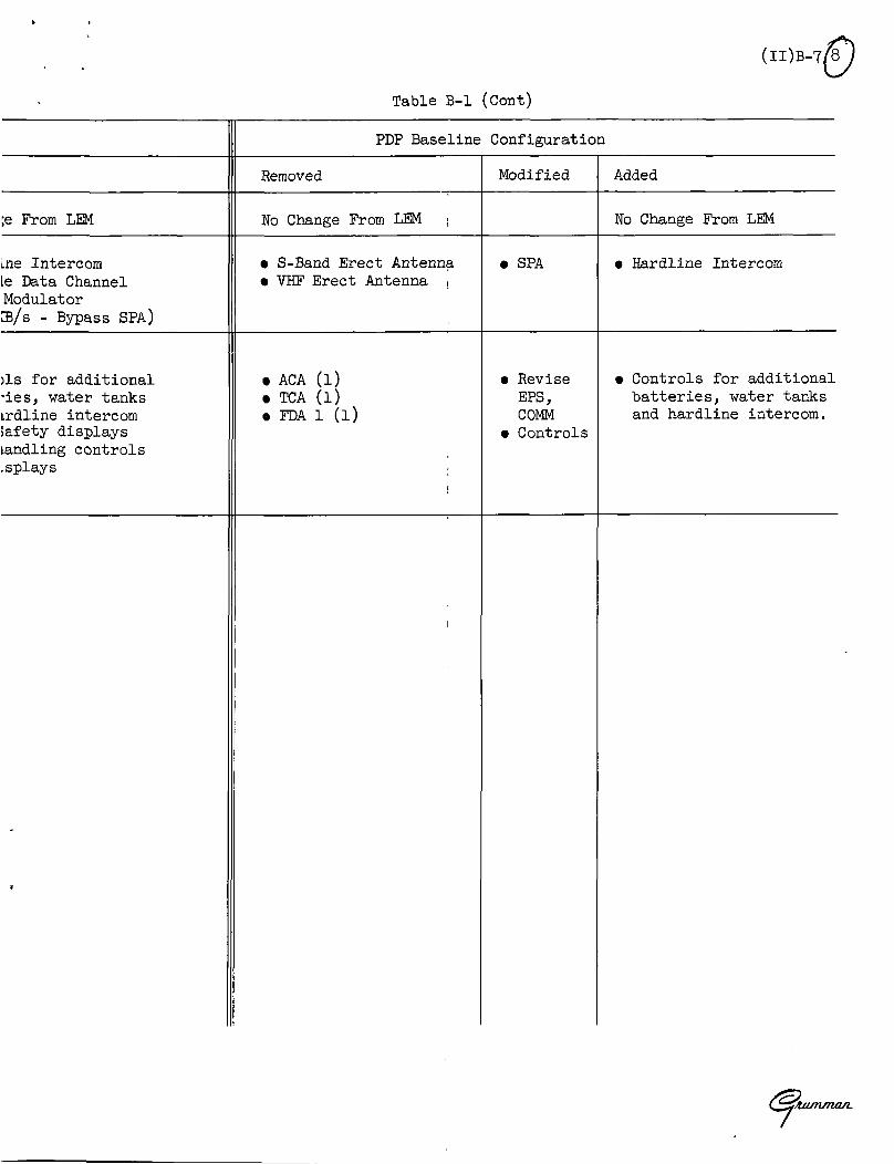
Table B-l (Cont)
PDF Baseline Configuration
Removed Modified Added
;e From LEM No Change From LEM No Change From LEM
Lne Intercomle Data ChannelModulatorS/s - Bypass SPA)
• S-Band Erect Antenna• VHF Erect Antenna ,
• SPA • Hardline Intercom
>ls for additional•ies, water tanksirdline intercomSafety displayslandling controls.splays
• ACA (l)• TCA (1)e FDA 1 (l)
• ReviseEPS,COMM
• Controls
• Controls for additionalbatteries, water tanksand hardline intercom.

Vehicle
ChangeItem
1.0Structure(Ascent)
(Descent)
2.0Stabilization& Controls
3-0Navigation &Guidance
Recommended Configurat
Removed
•Ascent Engine Cover•Propellant Tank Supts•Water Tank Supports•Battery Supports•GOX Tank Supports•Prop. Tank Shielding•Base Heat Shield*•Battery Supports
•GDA•DECA
•Landing Radar•Rendezvous Radar•IMU•LGC•PTA•PSA•CDU
Crew Provisions
Modified
•AEA (Softwechange todate starcatalogue)•Modify RGAproviderate•Change ratein ATCA to Ione pulsecycle
•Revise Ex1jlighting•Add furnid
^Vehicle Must Be Capable of Retaining All Items

ion
Table
PDF Baseline Co
Added Removed
•Airlock (No Specific-Recommendation)•GOX Tank Supports•SOX & SH2Tank Supts.•Fuel Cell Supts.•RCS Tank Supts.•Radiator Supt s.•Lower Deck Insula-tion•Water Tank Supts.
•Ascent Engine Cover•Propellant Tank Sup•Water Tank Supports•Battery Supports•GOX Tank Supports•Prop. Tank Shieldin•Base Heat Shield*•Battery Supports
'6
:como-
;o:r
gaininsureirait
•DECA*
•Landing Radar•Rendezvous Radar*•IMU*•LGC*•PTA*•PSA*•CDU*•DSKY*
rnal
ings
•Provide capabilityfor .kk backpackrecharges (assumerechargablebatteries)•Airlock--suit loop in"•Add battery charger
i Witn Asterisk
3-2 Phase II Laboratory
"iguration
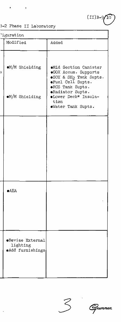
Modified Added
•M/M Shielding
•M/M Shielding
•Mid Section Canister•GOX Accum. Supports•SOX & SH2 Tank Supts.•Fuel Cell Supts.•RCS Tank Supts.•Radiator Supts.•Lower Deck* Insula-tion•Water Tank Supts.
•AEA
•Revise Externallighting
•Add furnishings
Vehicle Recommended Configuration
Change RemovedItem
Modified
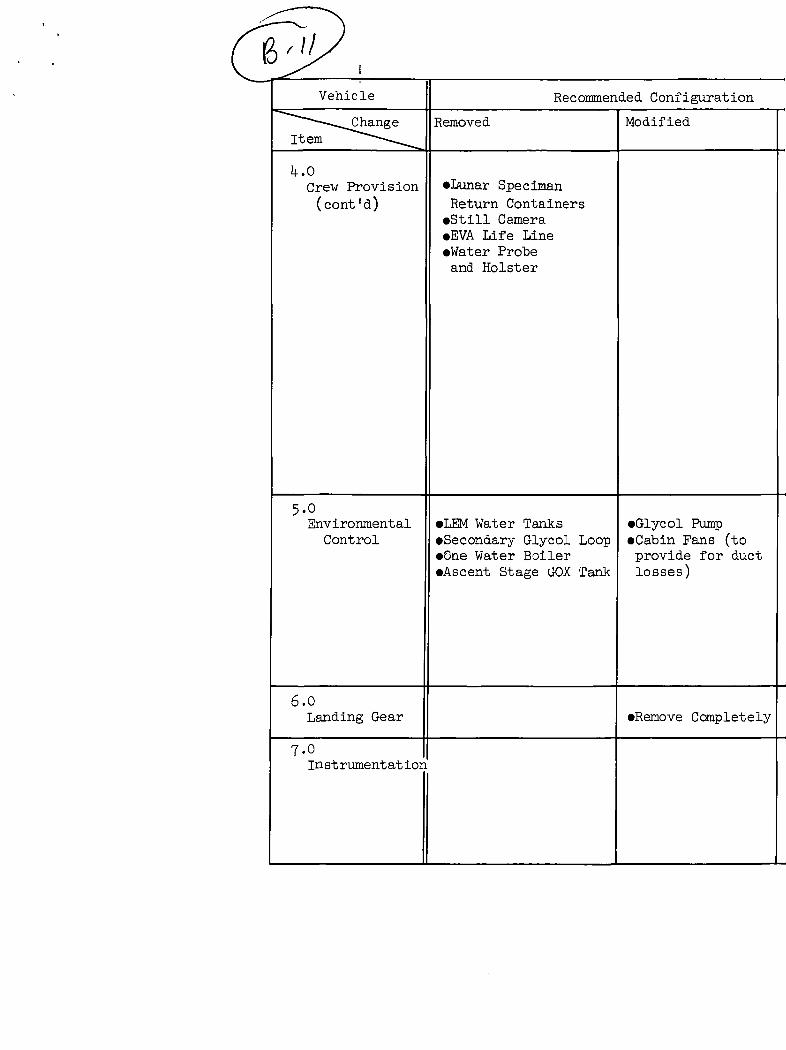
k.OCrew Provision(cont'd)
•Lunar SpecimanReturn Containers•Still Camera•EVA Life Line•Water Pro"beand Holster
5.0EnvironmentalControl
•LEM Water Tanks•Secondary Glycol Loop•One Water Boiler•Ascent Stage GOX Tank
•Glycol Pump•Cabin Fans (toprovide for ductlosses)
6.0Landing Gear •Remove Completely
7.0instrumentation
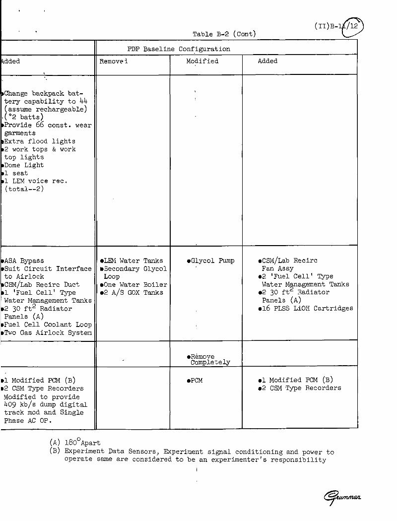
Table B-2 (Cont)
PDF Baseline Configuration
^dded Remove i Modified Added
iChange backpack bat-tery capability to kh(assume rechargeable).(°2 batts)»Provide 66 const, weargarments>Extra flood lights»2 work tops & worktop lights•Dome Light•1 seat1 LEM voice rec.(total—2)
•ASA Bypass•Suit Circuit Interfaceto Airlock•CSM/Lab Recirc Duct•1 'Fuel Cell' TypeWater Management Tanks»2 30 ft2 RadiatorPanels (A)•Fuel Cell Coolant Loop•Two Gas Airlock System
•LEM Water Tanks(•Secondary GlycolLoop•One Water Boiler•2 A/S GOX Tanks
•Glycol Pump •GSM/Lab RecircFan Assy•2 'Fuel Cell' TypeWater Management Tanks•2 30 ft2 RadiatorPanels (A)•16 PLSS LiOH Cartridges
•RemoveCompletely
»1 Modified PCM (B)•2 CSM Type RecordersModified to providek09 kb/s dump digitaltrack mod and SinglePhase AC OP.
•PCM •1 Modified PCM (B)•2 CSM Type Recorders
(A) l80°Apart(B) Experiment Data Sensors, Experiment signal conditioning and power to
operate same are considered to be an experimenter's responsibility
VehicleChange
Item
8.0ElectricalPower Supply
9.0Propulsion
10.0RCS
11.0Communications
12.0Displays &Controls
Recommended Configuration
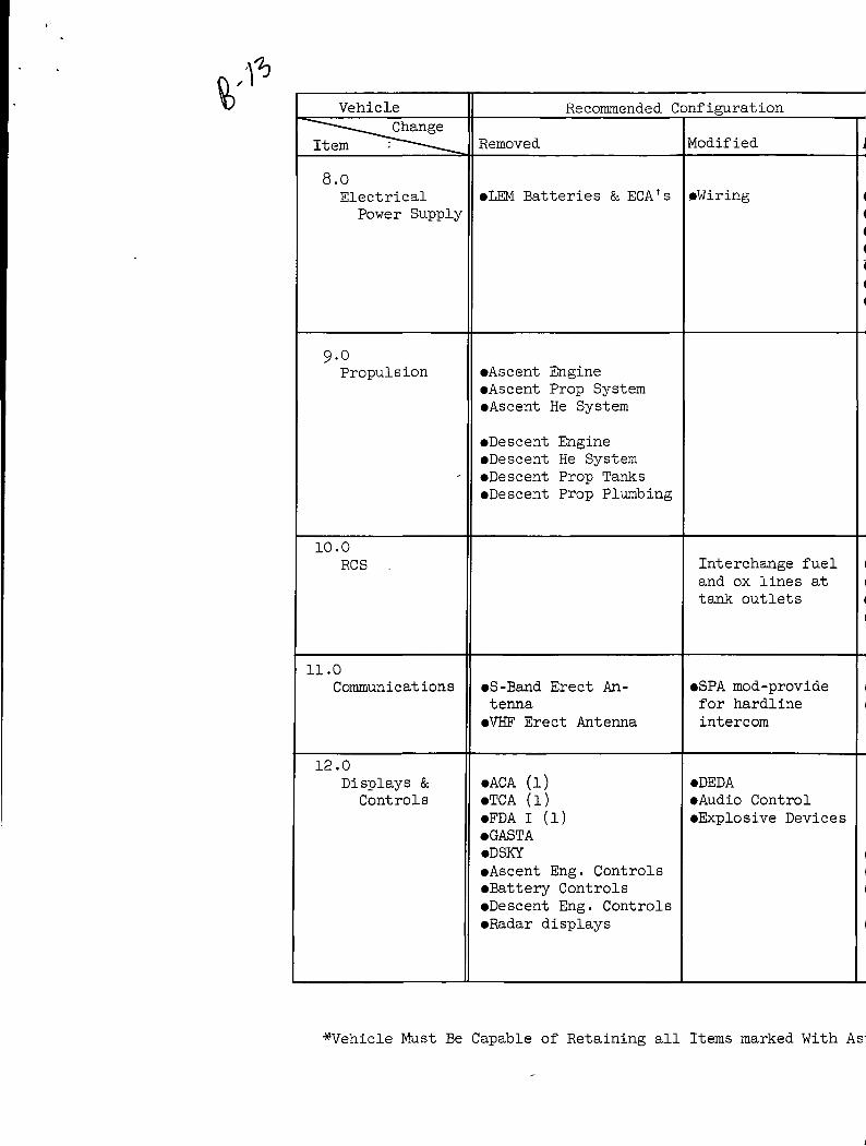
Removed
•LEM Batteries & ECA's
•Ascent Engine•Ascent Prop System•Ascent He System
•Descent Engine•Descent He System•Descent Prop Tanks•Descent Prop Plumbing
•S-Band Erect An-tenna•VHF Erect Antenna
•ACA (l)•TCA (1)•FDA I (1)•GASTA•DSKY•Ascent Eng. Controls•Battery Controls•Descent Eng. Controls•Radar displays
Modified
•Wiring
Interchange fueland ox lines attank outlets
•SPA mod-providefor hardlineintercom
•DEDA•Audio Control•Explosive Devices
•"Vehicle Must Be Capable of Retaining all Items marked With As1
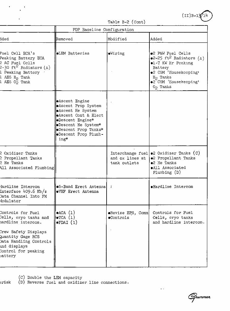
Table B-2 (Cont)
PDF Baseline Configuration
ided Removed Modified Added
Fuel Cell ECA'sPeaking Battery EGA2 AC Fuel Cells2-30 ft2 Radiators (A)L Peaking Battery -L AES Hg TankL AES 02 Tank
•LEM Batteries •Wiring •2 P&W Fuel Cells•2-25 ft2 Radiators (A)•1-7 K¥ Hr PeakingBattery•2 GSM 'Housekeeping'H2 Tanks•2 GSM 'Housekeeping'C> Tanks
•Ascent•Ascent•Ascent•Ascent•Descent•Descent•Descent•Descenting*
EngineProp SystemHe SystemCont & ElectEngine*He System*Prop Tanks*Prop Plumb-
2 Oxidizer Tanks2 Propellant Tanks2 He Tanks
Associated Plumbing
Interchange fueland ox lines attank outlets
•2 Oxidizer Tanks (c)•2 Propellant Tanks•2 He Tanks•All AssociatedPlumbing (D)
iardline IntercomInterface 09.6 Kb/sData Channel Into FMModulator
•S-Band Erect Antenna•VHP Erect Antenna
•Hardline Intercom
Controls for FuelHells, cryo tanks andoardline intercom.
2rew Safety DisplaysQuantity Gage RCSData Handling Controlsind displaysControl for peakingmttery
•ACA (l)•TCA (l)•FDAI (l)
•Revise EPS, Comm•Controls
Controls for FuelCells, cryo tanksand hardline intercom.
;risk(C) Double the LEM capacity(D) Reverse fuel and oxidizer line connections.

Vehicle Recommended
Item
Change withto
LEMrespect Removed Modified
1.0Structure Ascent Engine Cover
Engine BlastAscent PropellantDeflector &Helium Tanks
Food StorageAdditional InsulationIncrease Micrometeor-ite ShieldingWater Tank MountingSupports (conductivitychange)
2.0Stabilization &Control
Rate Gyro AssemblyAbort Guidance Sys
3-0Navigation &Guidance
• Rendezvous Radar• Alignment Optical
Telescope (AOT)
U.OCrew Provisions Soft Suits
Radiation DosimetersLiquid Cooled GarmentsBio-InstrumentationThermal/AntiMeteoroid Protect. GarmentsSuit Repair KitCrewCrew RestraintsLEM Waste Management

(ll)B-15/fL6Table B-3 Shelter
PDF Baseline
led Removed Modified Added
/indow coversfop. Hatch coverBattery SupportsCanister for WasteRadiator SupportsSupports for CrewProvisions
Ascent Engine CoverEngine Blast Deflec-torAscent Propellant &Helium Tanks
Food StorageAdditional Insula-tionIncrease Micro-meteorite ShieldingWater Tank Mount-ing Supports(conductivity
change)
Window coversTop Hatch coverBattery SupportsCanister for WasteEadiator SupportsSupports for CrewProvisions
3-band antenna X-YScanner3rogram CouplerAssembly
Abort Guidance Sys.
Pransponderluto. StarPracker Assembly
Rendezvous Radar BeaconMission Programmer(less paper tapereader)
Airlock3ne Hard Suit^ditional PLSSBatteriesPwo Additional PLSSAdditional PLSSSpare Partsih Constant .WearGarmentSxercise, Recreation'e, Hygienic Equipment[Vo Bunksfork Stations)ome & Work ToplightsAdditional Food\dditional PLSS LiOHfedical Equipment!!SM Waste Managementilxternal flood lightsj150W)
Soft SuitsRadiation DosimetersLiquid Cooled Garment'sBio-Instrumentation IThermal Garment IMeteoroid Protect GarmentsSuit Repair KitEmergency 0^ SystemCrewCrew RestraintsLEM Waste Management
One Hard SuitAdditional PLSSBatteriesTwo Additional PLSSAdditional PLSSSpare PartsIk Constant WearGarmentExercise & RecreationEquipmentTwo BunksWork StationsDome LightAdditional FoodAdditional LiOHMedical EquipmentCSM Waste Management
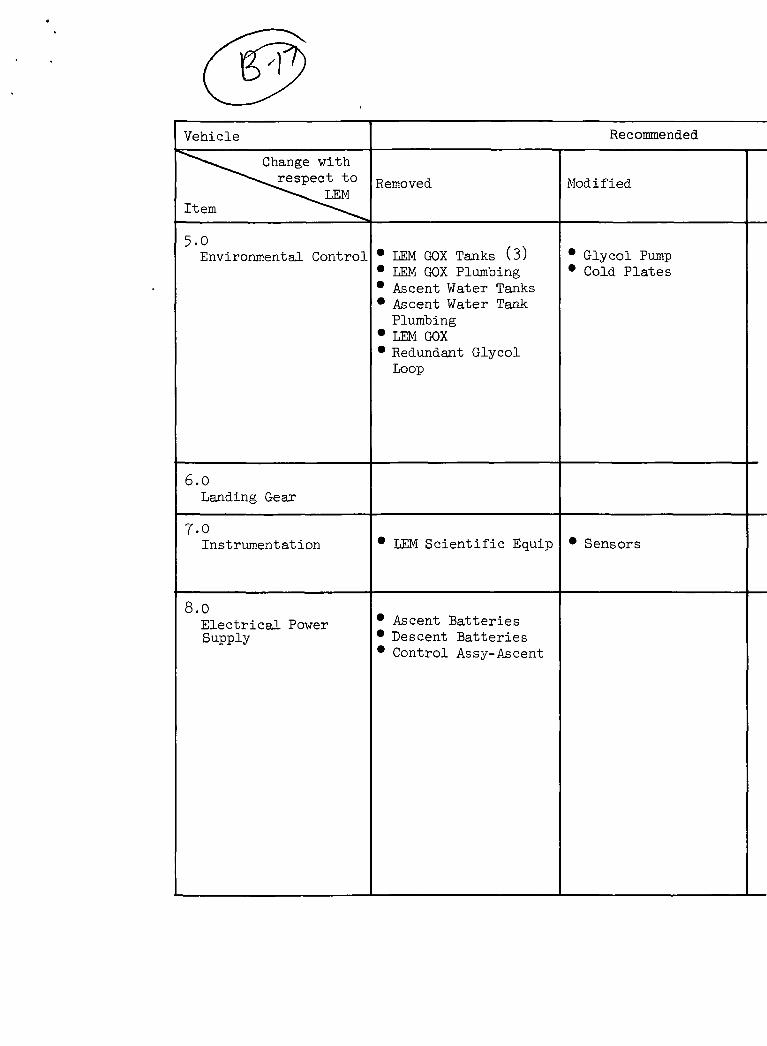
Vehicle Recommended
Item
Change withrespect to
LEMRemoved Modified
5-0Environmental Control LEM GOX Tanks (3)
LEM GOX PlumbingAscent Water TanksAscent Water TankPlumbingLEM GOXRedundant GlycolLoop
* Glycol Pump• Cold Plates
6.0Landing Gear
7.0Instrumentation LEM Scientific Equip Sensors
8.0Electrical PowerSupply
• Ascent Batteries• Descent Batteries• Control Assy-Ascent

(11)3-17,1
Table B-3 (Cont)
Ided
PLSS -SupplementaryGOX TankTanks for AC FuelCell WaterManagementPlumbing Assoc. withFuel Cell Water Man-agement*12 Cabin LiOH Car-tridgesGOX for PLSS Sup-plement75 ft2 RadiatorHeat Pipe for Usewith RTG
(l) Additional VoiceStorage RecorderCartridge
Three ModifiedDescent Batteries(12.0 kwh)Battery ChargerTwo AC Fuel CellsFCA Radiator andglycol pumpOxygen Tank (Vfin-. D.) (l)Hydrogen Tanks (39in. D) (2)PlymbingOxygen (AmbientStorage)Hydrogen (AmbientStorage)RTG Unit
Removed
LEM GOX Tanks (3)Ascent Water TanksAscent Water TankPlumbingLEM GOXRedundant GlycolLoop
• Data Storage* LEM Scientific Equip
* Ascent Batteries• Descent Batteries* Control Assy-Ascent• Two Descent ControlAssembly
PDP Baseline
Modified
• Glycol Pump• Cold Plates
• Sensors
Added
• PLSS SupplementaryGOX Tank
• Tanks for Fuel CellWater Management
* Plumbing Assoc. withFuel Cell Water Man-agement
• 12 Cabin LiOH Car-tridges
• GOX for PLSS Supplement• 75 ft2 Radiator• Heat Pipe for Use withRTG
• Two Modified DescentBatteriesBattery ChargerStorage BatteryTwo P&W Fuel CellsOxygen TanksHydrogen TanksPlumbingOxygen (AmbientStorage)
* Hydrogen (AmbientStorage)
• RTG Unit
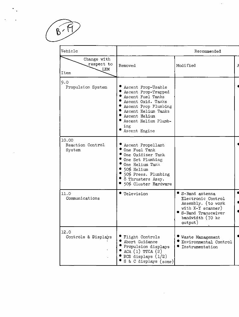
Vehicle Recommended
Item
Change withto
LEMrespect Removed Modified
9-0Propulsion System Ascent
AscentAscentAscentAscentAscentAscentAscentingAscent
Prop-UsableProp-TrappedFuel TanksOxid. TanksProp PlumbingHelium TanksHeliumHelium Plumb-
Engine
10.00Reaction ControlSystem
Ascent PropellantOne Fuel TankOne Oxidizer TankOne Set PlumbingOne Helium Tank50$ Helium50$ Press. Plumbing8 Thrusters Assy.50$ Cluster Hardware
11.0Communications
• Television S-Band antennaElectronic ControlAssembly, (to workwith X-Y scanner)S-Band Transceiverbandwidth (70 kcoutput)
i
•
12.0Controls & Displays Flight Controls
Abort GuidancePropulsion displaysACA (l) TTCA (2)RCS displays, (1/2)S & C displays (some)
* Waste Management* Environmental Control* Instrumentation

(II)B-I
Table B-3 (Cont)
PDF Baseline
ded Removed Modified Added
Vent Valves(3) to DescentPlumbing
Ascent Prop-UsableAscent Prop-TrappedAscent Fuel TanksAscent Oxid. TanksAscent Prop PlumbingAscent Helium TanksAscent HeliumAscent Helium Plumb-ingAscent Engine
• Vent Valves(3) to DescentPlumbing
Vent ValvesProp. tanks
to 336 Ib. PropellantOne Fuel TankOne Oxidizer TankOne Set PlumbingOne Helium Tank50$ Helium50$ Press. Plumbing8 Thrusters Assy.50$ Cluster Hardware
Command Decoder& assoc. electronicsAntenna switchingmatrixCommand Receiver
Television Command Decoder
Electric Power<FCA)
Flight ControlsAbort GuidanceControllersAscent Propulsion
" Waste Management• EnvironmentalControl
* Instrumentation
* Electric
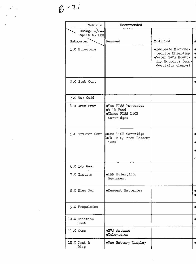
Vehicle
^\ Change w/re-spect to LEM
Sub system ^ ^
1 . 0 Structure
2.0 Stab Cont
3.0 Nav Guid
4.0 Crew Prov
5.0 Environ Cont
6.0 Ldg Gear
7.0 Instrum
8.0 Elec Pwr
9.0 Propulsion
10.0 ReactionCont
11.0 Comm
12.0 Cont & •Disp
Recommended
Removed
•Two PLSS Batteries•4 Ib Food•Three PLSS LiOHCartridges
•One LiOH Cartridge•24 Ib ©2 from DescentTank
•LEM ScientificEquipment
•Descent Batteries
•EVA Antenna•Television
•One Battery Display
Modified
•Increase Microme-teorite Shielding•Water Tank Mount-ing Supports (con-ductivity change)
A
•••
•
•
•
•
0
••
•
•
•

Table B-U Taxi(II)B-21X22
•
Ided
Window CoversPop Hatch CoverBattery Supports
t
9
?ime Programmer''or Status Datatransmission
tater Added for Dayflissionleat Pipe for use withOTGJattery Cooling/IMU-^SA Bypass.?ater tank heaters
'revisions for RTG?hree Modified DescJatteries (12.0 kw-hr)
?hree Vent Valves to)e scent Plumbing
>50 W Heater to eachtCS Cluster
tTG displays
PDF Baseline Configuration
Removed
•PLSS CalibrationUnit•Two PLSS Batteries•U Ib Food•Three PLSS LiOHCartridges
•One LiOH Cartridge•2U Ib 02 from DescentTank
•Data Storage•LEM ScientificEquipment
•Descent Batteries•Three Descent Electrical Control Assys
•EVA Antenna•Television
Modified
•Increase Micro-meteoriteShielding•Water TankMounting Supports(conductivitychange )
>
•
i
1
i
•Slight Modif i- _cation
Added
•Window Covers•Top Hatch Cover•Battery Supports
•Time Programmerfor Status Datatransmission
•20 Ib Water Addedfor Day MissionoHeat Pipe for Usewith RTG•Battery Cooling/IMU-ASA Bypass .•Water tank heaters
•Provisions for RTG•Three Modified DescBatteries
•Three Vent Valvesto Descent Plumbing
•250 W Heater toeach RCS Cluster

(11)3-23*
CQ
Ipq
OJ
coEH
QJ0GQJ
QJ ' — tin C
CO QJ OQJ K -H-P -PCO 0 COC -P rl
QJ -P 5)-P 0 -rlrH QJ <rl<; ft a
CO OQJ O
c~]-p•H
*- X
sH3
0EH-PoQJftCQQJK
-P•H
•dQJ•d
•dQJ•H
tt— 1•Pn
oS
QJ
0aQJ
QJbOcjjU
§-PH
J_)
QJ-p CQ CQ Cro .p -p -P 0p ^ a v -HS 0 QJ X +3,G ft a y CO QJEH ft ft co bD a
P -H rH -H ciCQ CQ PW > pqO cs1 coW H S
ao £•rH fi
GJ Cd CfHbD rl -Pco co co-P ft rHCQ QJ S PM
CQ QJ-P -P CQG QJ CQ CQQJ bO >j QJ0 Cd CQ LtCQ -P hi)< CQ H
QJ
p-PO
g-PCQ
O
rH
-
S-p
>> CQrH ^s^O £Qg
QJ QJCQ OCQ C
<^ CO
0 -H
P^ c5C5
QJ rl-P 003 ,0K <
08Co
•H-Pco i — 1-H O
•H f-{H -P•H Gr° 0cd o-pCQ
O
CM
lcd*dcdry
CQP0
QJ-daQJ
^
fa>H QJ
! ' ' 1
X ft rl^1 P QJ
+3 QJ O .*!G ^i TJ U O
<J QJ fl cdC O S r l
C CD ra 5-i co CQcd O G bD CQ O CQpq CQ cd O <; -p <
1 rl M PCQ EH PM <;
^jCD
r&
PH
CQ
§!>td
'dG EHQJ O«<
08G QJO O•H C-p cdcd "dbO-H
•H P> 0cd
Ooo
_
• N.
rM
O
eEH
0-P
ajQ
too
•rHH
1<
-PO£5
•dQJ
emov
PH
CQao•HCQ•H
15£_l
>cuJ_l
o
d<
CQGo•HCQrH
O£H
PM
CDf_^
0
C5
^
bOG•HHOOO
•H•p aO QJ< -P
•H >ia CQQJ
CQ
ft CQg QJP -P
PM cdH
OO rrj
r^^O O
j_3
oftftp
CQ
QJ^H•H"-1
**
•d-pG *QJ H
2 ^Ho -prl G•rl 0
> 0GH
O
lA
bD§("1oo
CO(p
bQG•H
Co>-H
oVO
CO
oCQ <£G CdQJ 0
CQ CQ
O•H
QJ <HM-H -pcd -P Grl C QJO QJ g40 »rH ftCQ O -H
Id S W
Q l-~l
GO•H
cd
1rfp
-pCOJ5H
O
C-
|
4^ -iCO t>i JC~{
PQ ^H 'd) >
-p -p 5C3 +3 LT\ <Jcd <ij cd or ^J pp ^J p-rl
|"^|=8QJ G ' G >sp^ c3 ^ ^ ?H
r J 'ti (D
Q) >s « QJ -P> M LCN W +3O QJ COa -P > -d pqQJ QJ T)
PC tt <ij
-pG <;QJ O0 HCO<^ 08
-p >>ro QJ*d -pG -PP co
Td pqQJK
1
CO -pQJ ft
•H QJrl OQ) ><-P 043 vcdpq to
f-t•P QJG -P0) rlO QJ ^^CQ > QJQ) G GQ H O
*•>J
"ftp.
'coco'O
•H £HJH QJ•P teO O0) CMrHW
0
CO

0a00H0
K^ao o-P -H
CQ -P0 -P co
-P O ?HCO 0 Pfl ft 60En CQ -H0 0 CH
-P ^H E3H 0< £l O
-P•HJs
— ,
K!1-3o-p.po0ftCQ0Kc~|-P•H12
>d0<d
^
•d0
•HCH•H"d
S
-d0
i0
PH
<utiO
cdr£3O
S0-pH
-p aCQ C O0 0 -rl bO> o co aH CQ rH -HCO 0 P ,g
O £3-P 0 rH rHO -p PH PH0>
a-pCO
CO
ao•HCQH
0£_l
PH
-paoCQ
no•HCQ
rj
ft
0
PH
0•
ON
* 0
•P "
3 ^8 oC _H.P 1 CQ
(Jo 6D J•rH r -pCH ^ CQ
O i — 1CJ ° O
r<
^ 0 00 -P rH
-P CQ ,0CQ P -r)
P r< -d
r< 43 aft EH 0EH -P
CO H H
60aCO -H0 ,£>
•3 5> PH
-P 0a -P0
0rH CQ60 O 0EH _JS i — 1^ cH tQ
Nl-p tH O
O
0
G cd^ -H >Q bO ,13 CQ 'd
"q EH -H "n P co11 cdO3 r j rQ 03 ' 1 CO M
H S !n S EH P-i <H 03 0 p ^ fn0 PH N rH dS * ^H 0f t • H Q H p P C Q 0 - PO H <d -H -H CQ +3 CQ£n 0 *H -p i — I ' — 1 0 CQ p
PH P W 0 0 0 ^ P rHprj Q ^Q jr~{ [Xj p_j H O
o c~]H 0 0 0 0 "?6-" - EH ~^-
VD O O O O UN LACO LT\rono
rHa oO JH•H -p-P flO Oo3 o0
PH1
o•o
rH
60a•H
GcdjaoOcd(D
PP
^H 10 ^H'd oO 4-) XO -H -H0 > £HQ CO -P
CO
G SHTO C t30S d) GS "^ 4-^ 'rHo o a0 Q 3,
ao•HCQ•HJ>
H0
EH
CQao•H
3O•HaJ3ggoo
o•
HH
CQ0 rH•H O-P r<CO HPR r*O O-P O
CQ
i??HftCQ•HQ
•dGoj
CQHo
-1-pa0oH
5!
08 CQ
CQ OjH H0 ft!M CQ4^ -Ha POO
O•
OJrH
*
CQCQ<J
a0•H-pcorH
Orl•HO0
PH
-P
9Ho0o
•fn0rH•rHO
^_l
0-P
1
•V
o-pcdrHPa£3oo
H •O 0
rH -PC5 CO
•\ 4JrM C
EH 003 O
EH CQ0
JH Q0+? °o3 -P*2
.. 00 -P60 o3CO ^-P OCO H
0-P r<a0 COCJ 0
0 rlQ 0
-P
o -P-P cd
,0
"^o ^a
COCQ CO
0 S-P PMM 1^1
^C 5^
*
-P§o
LT\
pq
03EH

OO
CO
LU
COLU<
O
X
oz.LUQ_Q.
REMA
RKS
No-
^ 1§
°g
gsg
« l|LU (£
» Isog
N3 fi
g i§iiN
a »o:
Oe
i
4
3E
L
ii
e
II
RADA
R S
EC
TIO
N• 1
[R
END
EZVO
US
RADA
RLA
ND
ING
RA
DAR
TRAN
SPO
ND
ER
1 •
• 1
• •
CO
NTR
OL
ELE
CTR
ON
ICS
SEC
TIO
NAT
TITU
DE
CO
NTR
OLL
ER A
SSY
...
II
)
ii
! |IIISlrts^is= s"s:I:iZ -I g U
iiii
o10
If1
1
u
I
:
IfN
•
•
QC
5
•
SEQ
UEN
CER
ASS
YX-
Y S
CA
NN
ER
PRO
GR
AM
CO
UP
LER
ASS
V
HE
LIU
M
PRES
SUR
IZAT
ION
SE
CTI
ON
PLU
S PL
UM
BIN
G
1R
R
EM
OV
E 1
HE
, O
X,
1 PR
OPE
LLAN
T TA
NK
SP
IUS
PLU
MB
ING
S
g TH
RU
STER
S 1
•
•
>
•
i1:
oB
>J B
) JJ
ii
0tp0JH
•
I tq
PR
OP
UL
•
•
\
CR
YOG
ENIC
LI
NE
S S
ECTI
ON
1
••
«
•
HYDR
OG
EN C
RYO
GEN
IC H
EAT
EXC
HAN
GER
OXY
GEN
CR
YO
GE
NIC
H
EAT
EX
CH
AN
GE
RH
EAT
TRAN
SPO
RT
SE
CTI
ON
, PR
ESS
AREA
CA
BIN
TEM
P rn
HT
VA
IVr
•
•
I
1 .
1
1 .
• »
• ilsl|S s 3
Jf 3
|i|s i •-
Hi
•,
•
*<
•j
H39N
VH
3X3
J.V3H
N393IT
1NV
I003
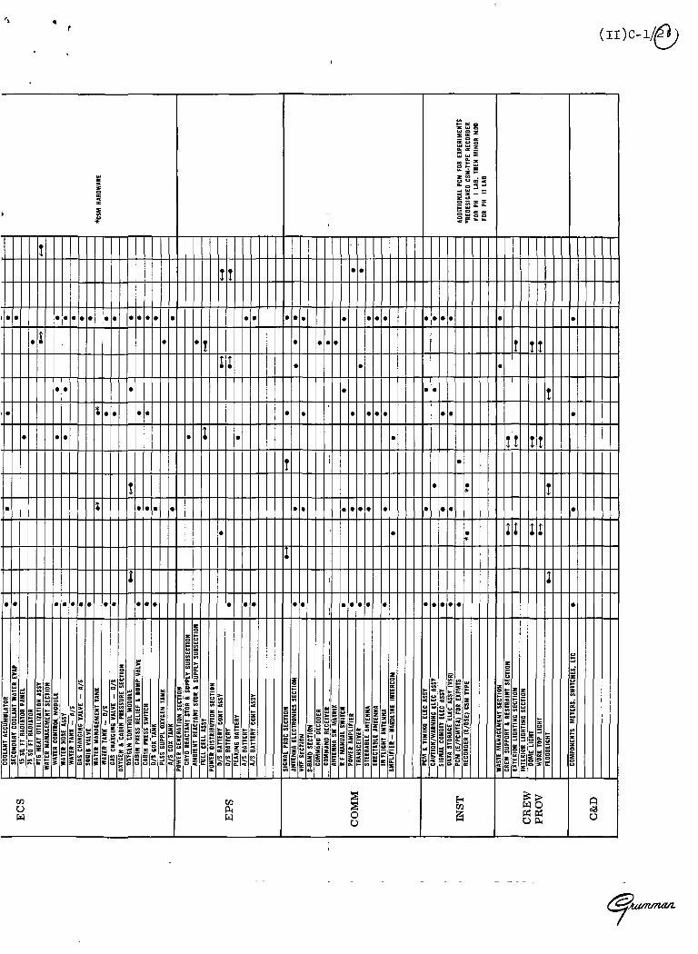
I
.1
•
•
• •
•
jlsjjl! 1 1 1 5 i *
CO
ow
ec
EC
X
» •
*.. .1
!*
I
zo
0 « £j
T 1 Tag
7* |T*«|
o
•
..
E
* K
. X
: u1 (0
J 0
•
•
xKX
e.
J!Is' W)J i1-*
•
•
CRYO
REA
CTA
NT
STO
R I
SUPP
LY
SUBS
ECTI
ON
AMBI
ENT
REA
CTA
NT
STO
R (
SUPP
LY
SUBS
ECTI
ON
I
i
i
n
n
<
•
< »
X >
i £ 2
sg!s
«rt w <
CO
w
1
10
U M
•
•
•
I
•
i
SIG
NAL
PRO
C SE
CTIO
NAN
TEN
NA
ELEC
TRO
NICS
SE
CTI
ON
•
i
•
S-BA
ND
SEC
TIO
NCO
MM
AND
DECO
DER
••
__
COM
MAN
D R
ECEI
VER
. .
_AN
TENN
A SW
MAT
RIX
•
»
•
• •
Ulr-±
IUJ
*C.
•
•
•
1E
4
11
1)
•
•
EE
C<t
3
1
•
EE
•
•
eE
e
c9
E
•
•
X3
U
u
1
i
••
•
I
CAUT
ION/
WAR
NING
ELE
C AS
SY
•
•
SIG
NAL
CO
NDIT
ELE
C AS
SY
•
•
\a
u
E
ADD
ITIO
NAL
PC
M F
OR
EXP
ERIM
ENTS
|
•PC
M (
E/P
CM
TEA
) FO
R EX
PMTS
cr§
^RED
ESIG
NED
CSM-
TYPE
REC
ORDE
R
*
t
RECO
RDER
(E
/DS
E)
CSM
TYP
EFO
R PH
1
LAB,
TH
EN M
INO
R M
OD
2
X
3•
V
11
WAS
TE M
ANAG
EMEN
T SE
CTIO
NCR
EW S
UPPO
RT I
RES
TRAI
NT
SECT
ION
I
I
iIN
TER
IOR
LIG
HTI
NG
SEC
TIO
N
ffr
ftC
I
I
I
E3
UlE3
3ii
I
I
I
Ea
3
e
E
>
H
I
I
1
FLO
ODL
IGHT
•
•
COM
PONE
NTS
MET
ERS,
SW
ITCH
ES,
ETC
e0,
c,i
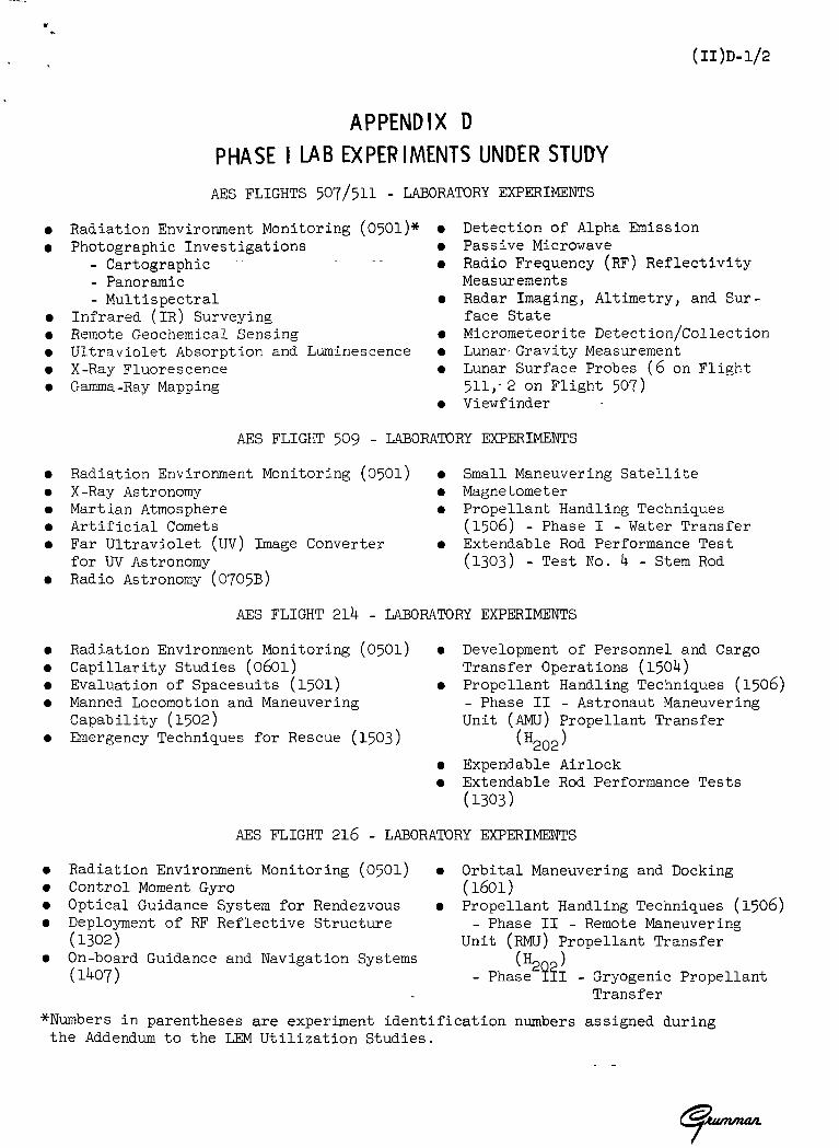
APPENDIX D
PHASE I LAB EXPERIMENTS UNDER STUDY
AES FLIGHTS 507/511 - LABORATORY EXPERIMENTS
• Radiation Environment Monitoring (0501)*• Photographic Investigations
- Cartographic "" "- Panoramic- Multispectral
Infrared (IR) SurveyingRemote Geochemical SensingUltraviolet Absorption and LuminescenceX-Ray FluorescenceGamma-Ray Mapping
• Detection of Alpha Emission• Passive Microwave• Radio Frequency (RF) Reflectivity
Measurements• Radar Imaging, Altimetry, and Sur-
face State• Micrometeorite Detection/Collection• Lunar- Gravity Measurement• Lunar Surface Probes (6 on Flight
511,- 2 on Flight 50?)• Viewfinder
AES FLIGHT 509 - LABORATORY EXPERIMENTS
Radiation Environment Monitoring (0501)X-Ray AstronomyMartian AtmosphereArtificial CometsFar Ultraviolet (UV) Image Converterfor UV Astronomy
• Radio Astronomy (0705B)
••
Small Maneuvering SatelliteMagnetometerPropellant Handling Techniques(1506) - Phase I - Water TransferExtendable Rod Performance Test(1303) - Test No. k - Stem Rod
AES FLIGHT - LABORATORY EXPERIMENTS
Radiation Environment Monitoring (0501)Capillarity Studies (0601)Evaluation of Spacesuits (1501)Manned Locomotion and ManeuveringCapability (1502)Emergency Techniques for Rescue (1503)
Development of Personnel and CargoTransfer Operations (150U)Propellant Handling Techniques (1506)- Phase II - Astronaut ManeuveringUnit (AMU) Propellant Transfer
AirlockRod Performance Tests
ExpendableExtendable
(1303)
AES FLIGHT 216 - LABORATORY EXPERIMENTS
Radiation Environment Monitoring (0501)Control Moment GyroOptical Guidance System for RendezvousDeployment of RF Reflective Structure(1302)On-board Guidance and Navigation Systems
Orbital Maneuvering and Docking(1601)Propellant Handling Techniques (1506)- Phase II - Remote Maneuvering
Unit (RMU) Propellant Transfer(H2Q2)
- Phase III - Gryogenic PropellantTransfer
*Numbers in parentheses are experiment identification numbers assigned duringthe Addendum to the LEM Utilization Studies.
CONFIDENTIAL
Grumman A i r c ra f t Engineering Corporat ion • Bethpage, New York
CONFiucNTiAL4395
Top Related