


Languages
Pages
Legal


Condenser CoilsCoil construction is available for Condenser, Desuperheater, and Reheat applications.
Applications:• Condenser - This coil takes the superheated vapor from the compressor and cools that vapor
down to saturation. It then completely condenses all of the vapor into liquid, and continues to subcool the resulting liquid to a desired temperature below saturation.
• Reheat - This is a hot gas reheat coil which takes the superheated vapor from the compressor and cools the vapor down to saturation. It then continues to condense a requested percentage of that vapor to a liquid.
• Desuperheater - This coil takes the superheated vapor from the compressor and cools that vapor down to a requested temperature above saturation.
CONDENSER COIL CONSTRUCTIONTubing 3/8" or 1/2" O.D. Copper, 5/8" O.D. Copper, Stainless Steel, or Carbon SteelCircuiting Standard one section, Multiple sectionsRows 1, 2, 3, 4, 5, 6, 8, 10, 12Fin Surface Sine Wave (corrugated), New Ripple (peak and valley) or FlatCasing Galvanized Steel, Stainless Steel, Carbon Steel, Copper or AluminumConnections Copper Sweat, Carbon Steel or Stainless Steel

HEATCRAFT REFRIGERANT CONDENSER COIL SPECIFICATION 1.0 DESIGN PRESSURES AND TEMPERATURES Coils shall be designed to withstand 250 psi maximum operating pressures and a maximum temperature of 300°F for standard duty copper tube coils with standard headers. Higher limits are available, depending on coil construction and / or materials used. 1.2 FACTORY TESTING REQUIREMENTS Coils are to be pressurized and then completely submerged in warm water containing special wetting and final cleaning agents for leak testing and tested with a minimum of 315 psi air pressure for standard copper tube coils. A hydrostatic leak test is available upon request. Certified hydrostatic leak test and Certificate of Conformance also available upon request. Coils must display a tag with the inspector's identification as proof of testing. After testing coils are to receive a 5 lb. Nitrogen charge assuring the coil as received remains leak free and clear of internal contamination. 1.3 FINS Coils shall be of plate fin type construction providing uniform support for all coil tubes. Coils are to be manufactured with die-formed aluminum, copper, cupro-nickel, stainless steel or carbon steel fins with self-spacing collars, which completely cover the entire tube surface. Any manufacturer not capable of offering the full range of these materials shall be considered as unacceptable. Fin corrugations available shall include: Flat, Rippled and “Hi-F” Sine Wave for coils built with .625” OD tubes and utilizing a 1.5” equilateral tube pattern; Flat, Rippled and “Hi-F” Sine Wave for coils built with .50” OD tubes and utilizing a 1.25” equilateral tube pattern; “Hi-F” Sine Wave for coils built with .50” OD tubes and utilizing a 1.5” equilateral tube pattern; Rippled and “Hi-F” Sine Wave for coils built with .375” OD tubing and utilizing a 1.0” equilateral tube pattern; “Hi-F” Sine Wave for coils built with .375” OD tubes and utilizing a 1.25” equilateral tube pattern. Manufacturers not capable of producing the full range of these fin surface styles, corrugations and tube patterns shall be considered as unacceptable. Standard fin thickness’ available shall include: .0060” +/- 5% for aluminum and copper; .0075” +/- 5% for aluminum, copper, and cupro-nickel, carbon steel and stainless steel; .0095” +/- 5% for aluminum, copper, carbon steel and stainless steel; .016” +/- 5% for aluminum and copper. Manufacturers not capable of providing the full range of these fins thicknesses shall be considered as unacceptable. Fins are to be formed with full collar on all of available materials, corrugation styles, tube diameters and tube patterns. Manufacturers unable of providing full collars on the full range of fin offerings shall be considered as unacceptable. Fin spacing available shall include: 4-14 fins / inch on coils supplied with .625” OD tubing; 6-14 fins / inch on coils supplied with .50” OD tubing; 4-20 fins / inch on coils supplied with .375” OD tubing. Manufacturers with tooling not capable of providing full collar, die formed fins, accurately space with a tolerance of +/- 4% and not offering the full range fin spacing for the appropriate tube diameter shall be considered as unacceptable. 1.4 TUBING Tubing and return bends shall be fabricated from UNS 12200 seamless copper conforming to ASTM B75 for standard pressure and temperature applications. Elevated duty and special application construction tube cores shall be available in seamless 90/10 Cupro-Nickel Alloy #706, Stainless Steel ASTM #A249 grade 304L or 316L and Carbon Steel ASTM #A214 welded or #A179 Seamless. Core tubes (excluding hot dipped galvanized steel coils) shall be mechanically expanded to form an interference fit within the fin collars. Expansion shall not decrease the tube wall thickness. Coils shall be manufactured using return bends of the same material as the core tubing. Return bend wall thickness, at the outside circumference of the bend, shall be no less than the core tube wall thickness. The use of “hairpin” style tubes & return bends shall be unacceptable.

Available tube size and wall thicknesses shall be as follows: Material 0.375” O.D. 0.50” O.D. 0.625” O.D. 1.0” O.D.
Copper 0.013, 0.016, 0.020, 0.025, 0.030
0.016, 0.022, 0.030
0.020, 0.025, 0.035, 0.049
0.023, 0.035, 0.049
Cupro-Nickel 0.020, 0.035, 0.049 0.035, 0.049 Carbon Steel 0.035, 0.049, 0.065 0.035, 0.049
Stainless Steel 0.035, 0.049, 0.065 0.035, 0.049 Admiralty Brass 0.049
Coils shall be made available with copper tubes utilizing internally enhanced Rifled Surfacing when required. As a quality control measure, Coil Manufacturer shall be capable of providing copper rifled tubing, enhanced within it’s own facility, and not supplied by an outside source. As a further quality control measure, Coil Manufacturer shall be capable of supplying all of above listed extruded seamless copper tube sizes and wall thickness’ from their own, in house, Copper Tube Mill. Tube Mill shall be owned by the Coil Manufacturer and operated by trained personnel under the employ and supervision of said Coil Manufacturer. 1.5 HEADERS Headers shall be constructed from UNS 12200 seamless copper conforming to ASTM B75 and B251 with an H55 temper for standard applications. Other option for headers for high-pressure construction shall incorporate seamless 90/10 Cupro-Nickel Alloy #706 conforming to ASTM B111, Carbon Steel conforming to ASTM A53A or A135A, Stainless Steel conforming to ASTM A249, at Sch. 10 or Sch. 40, per the application requirements. Headers shall be manufactured using a Pierce and Flare die-punch method when possible. This shall insure that the tube-to-header tube hole intrusions into the header are such that the landed surface area contact length for joint brazing approximates three times the core tube wall thickness. Manufacturers not capable of providing headers of the Pierce and Flare design shall be considered as unacceptable. Standard construction shall be such that the core tubes will penetrate directly into the header without the use of intermediate adapter tube spuds, except where curving or splaying of headers is required. Each of these core tubes shall extend evenly within the inside diameter of the header to a depth no greater than 0.12 inch. In addition, and without exception, each of these core tubes penetrating the hot gas header(s) shall pass through an oversized hole in the sheet metal casing, of no less than 25% larger than the outside diameter of the core tube. This will prevent metal to metal contact between the tube and the sheet metal casing, allowing the header and core tubes to “float” and eliminating the possibility of premature failure caused by excess vibration from the compressor side (hot gas) of the coil. Manufacturers not capable of providing such floating headers shall be considered as unacceptable. End caps shall be precision die-formed and positioned inside the header so that the thickness of the brazed fillet joint approximates three times that of the header wall thickness. Manufacturers using standard copper tube end caps, which are brazed over the outside of the end of the headers shall be considered as unacceptable. 1.6 CONNECTIONS Standard construction of copper tube condenser coils shall allow for copper sweat connections for type L or K wall copper. Other materials shall be made available dependant upon the materials of construction of the tube core. 1.7 BRAZING & WELDING Oxyfuel gas brazing, using fillet rod material of minimum 5% silver shall be used for all non-ferrous tube joints to headers and connections. Ferrous to non-ferrous joints shall contain as much as 35% silver or may be Tobin bronze. Gas shielded arc welding shall be used for all stainless steel joints and also for nay ferrous tube joints made to compatible or alike material headers and connections.

1.8 CASING Coil casing and endplate shall be fabricated from Galvanized steel, as a standard construction, meeting ASTM and UL G90U requirements, Aluminum, 0.080” thick, optional, Copper, 0.063 “ thick, optional,16- or 14-gauge carbon steel or stainless steel, optional. double-flange casing shall be provided when coils are specified as vertical stacking. Standard coil intermediate tube sheets (center tube supports) shall be fabricated from the same gauge sheet stock and material as the end plates, and to the following schedule:
Finned Length (inches) Number of Tube Sheets 6.00 – 48.00 0 48.01 – 96.00 1
96.01 – 144.00 2 144.01 and greater 4
1.9 CERTIFICATIONS Coil manufacturer shall be certified and registered with the Air Conditioning and Refrigeration Institute (ARI) and shall be an active and current member of the ARI Standard 410 Air-Cooling and Air-Heating Coils certification program and shall have original coil line certifications and computerized selections dating back a minimum of 30 years, as proof of overall company performance, stability and longevity. Manufacturers not capable of meeting this requirement shall be considered as unacceptable. 1.10 AGENCY APPROVAL Coil manufacturer shall be registered by UL to ISO 9000 (ANSI/ASQC Q92). Applicable commercial coil models shall be UL Standard 207 and registered as Refrigerant Containing Components and Accessories; non- electrical. CRN (Canadian Registration Numbers) shall be provided for all coils shipping into Canada as requested. Coil manufacturer shall also possess ASME Section VIII Division 1, U and UM stamping certification as proof of acceptable quality control methods. Manufacturers unable to meet the above listed agency approvals shall be considered as unacceptable. 1.11 LEAD TIME AND SHIPPING Standard lead-time for custom made retrofit condenser coils of standard construction with OEM circuiting shall be 11-15 working days, with reduced lead-time emergency shipment options of 10 working days and 5 working days from order placement date and based upon production approval. Standard lead-time for custom made condenser coils of manufacturer’s own standard design and circuiting shall be 10 working days, with reduced lead-time emergency shipment options for 5 working days, 48-hours and 24-hours from order placement date. All coils shall be quoted and offered as FOB Factory, Full Freight Allowed to any and all destinations within the Continental United States. Manufacturer shall have the capability of delivering the product by means of it’s own shipping service, and without the use of outside contracted freight company or consolidator.
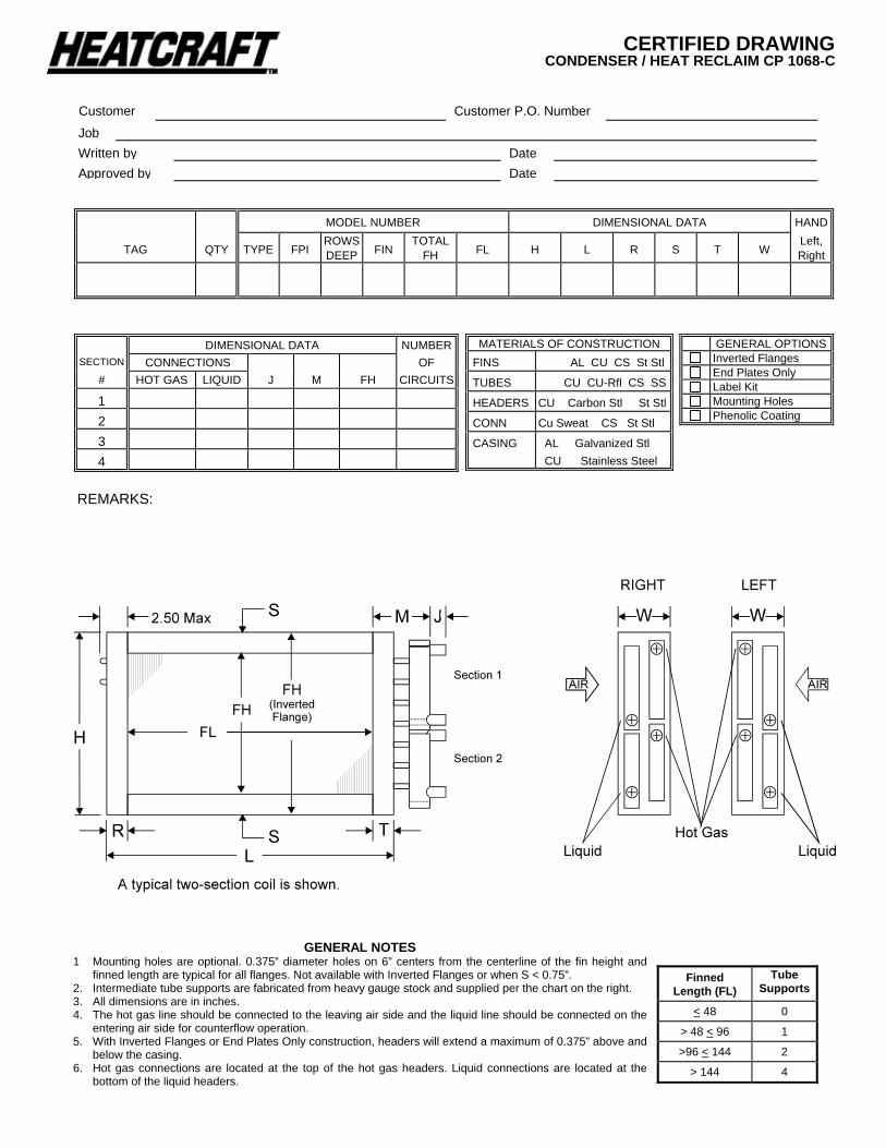
CERTIFIED DRAWING CONDENSER / HEAT RECLAIM CP 1068-C
MODEL NUMBER DIMENSIONAL DATA HAND
TAG QTY TYPE FPI ROWS DEEP FIN
TOTAL FH FL H L R S T W
Left, Right
DIMENSIONAL DATA NUMBERSECTION CONNECTIONS OF
# HOT GAS LIQUID J M FH CIRCUITS
1 2 3 4
Customer Customer P.O. Number
Job Written by DateApproved by Date
MATERIALS OF CONSTRUCTION FINS AL CU CS St Stl
TUBES CU CU-Rfl CS SS
HEADERS CU Carbon Stl St Stl
CONN Cu Sweat CS St Stl
CASING AL Galvanized Stl CU Stainless Steel
GENERAL NOTES 1 Mounting holes are optional. 0.375” diameter holes on 6” centers from the centerline of the fin height and
finned length are typical for all flanges. Not available with Inverted Flanges or when S < 0.75”. 2. Intermediate tube supports are fabricated from heavy gauge stock and supplied per the chart on the right. 3. All dimensions are in inches. 4. The hot gas line should be connected to the leaving air side and the liquid line should be connected on the
entering air side for counterflow operation. 5. With Inverted Flanges or End Plates Only construction, headers will extend a maximum of 0.375” above and
below the casing. 6. Hot gas connections are located at the top of the hot gas headers. Liquid connections are located at the
bottom of the liquid headers.
Finned Length (FL)
Tube Supports
< 48 0
> 48 < 96 1
>96 < 144 2
> 144 4
REMARKS:
GENERAL OPTIONS Inverted Flanges End Plates Only Label Kit Mounting Holes Phenolic Coating

Condenser CoilInstallationOperation
andMaintenance

CONDENSER IOM
Guidelines for the installation, operation and maintenance of Heatcraft’s refrigerant condenser coils havebeen provided to help insure proper performance of the coils and their longevity. These are generalguidelines that may have to be tailored to meet the specific requirements of any one job. As always, aqualified party or technician should perform the installation and maintenance of any coil. Protectiveequipment such as safety glasses, steel toe boots and gloves are recommended during the installation androutine maintenance of the coil.
Receiving Instructions1. All Heatcraft coils are factory tested, inspected and carefully packaged.
2. Damage to the coils can occur after they have left the factory. Therefore, the coils should beinspected for shipping damage upon receipt. The freight bill should also be checked againstitems received for complete delivery.
3. Damaged and/or missing items should be noted on the carrier’s freight bill and signed by thedriver.
4. For additional assistance, contact your local Luvata (Heatcraft Coil) representative.
Mounting1. Position the coil such that the liquid header is at the entering airside of the coil and the hot gas
header is at the leaving airside of the coil. This orientation provides counterflow heat exchange,which is required for proper coil performance. (Fig. 1)
2. The hot gas connection is located at the top of the hot gas header and the liquid connection islocated at the bottom of the liquid header when properly installed. (Fig. 1)
1
5 C N 14 06 C 24.00 x 144.00Tube O.D. Finned Length (inches)3=3/8”4=1/2” Fin Height (inches)5=5/8”Coil Type Fin DesignC = Condenser A - flat (Al, Cu)
B - corrugated (Al, Cu)Circuiting C - sine wave (Al, Cu)N = Normal - Single Circuit F - flat (SS, CS)F = Face Control - Multiple Circuits G - corrugated (SS, CS)
H - sine wave (SS, CS, Al, Cu)
Rows Deep
Fins Per Inch
Nomenclature

CONDENSER IOM
Coil Types (Condenser, Desuperheater, Reheat)1. Heatcraft coil model CN is used for applications where capacity control is not required for a
single compressor circuit.
2. Face control (model CF) is another coil option offered. Face control is the simplest form ofcapacity control. Type CF coils are normally furnished with two or more hot gas connectionsand two or more liquid connections offering various capacity reduction capabilities.
2
Figure 1 - Condenser Coils

CONDENSER IOM
Installation1. Carefully remove the coil from the shipping package to avoid damage to the finned area.
Damaged fins can be straightened using an appropriate fin comb.
2. Luvata recommends cleaning the coil with a commercially available coil cleaner prior to instal-lation. Refer to Maintenance on Page 4 for cleaning recommendations.
3. Proper clearance should be maintained between the coil and other structures such as the fan,guards, transition areas, etc.
4. All field brazing and welding should be performed using high quality materials and an inert gaspurge (such as nitrogen) to reduce contamination by oxidation of the internal surface of thecoil.
5. Connect any fittings, valves, and bypass lines to the coil.
6. Luvata recommends vibration suppressors between the incoming hot gas and liquid lines toguard against stress cracks in the connections and brazed joints.
7. Pressurize the coil, bypass line (if any), and connections to 100 psig with dry nitrogen or othersuitable gas. The coil should be left pressurized for a minimum of 10 minutes
8. If the pressure does not change, the hook-up can be considered leak free. If the pressuredrops by 5 psi or less, repressurize the coil and wait another 10 minutes. If the pressure dropsagain, there are more than likely one or more small leaks, which should be located and re-paired. Be sure to check valves and fittings as potential sites for leakage or bleed. If the coil isfound to be leaking, contact your local Luvata Heatcraft coil representative. Unauthorizedrepair of the coil may void the coil’s warranty (see Luvata’s warranty policy on page 5).
9. Use a vacuum pump to evacuate the coil and any interconnecting piping that has been open toatmosphere. Measure the vacuum in the piping using a micron gauge located as far from thepump as possible (the vacuum at the pump will be greater than the rest of the system). Evacu-ate the coil to 500 microns or less then close the valve between the pump and the system. If thevacuum holds to 500 microns or less for one minute, the system is ready to be charged orrefrigerant pumped down in another portion of the system can be opened to the coil. A steadyrise in microns would indicate that moisture is still present and that the coil should be furthervacuumed until the moisture has been removed.
10. Failure to obtain a high vacuum is indicative of a great deal of moisture or a small leak. Breakthe vacuum with a charge of dry nitrogen or other suitable gas and recheck for leaks (soapywater works well). If no leaks are found, continue vacuuming the coil until the desired vacuumis reached.
11. All field piping must be self-supporting.
12. Refer to Figures 2 - General Diagram, for general plumbing.
3

CONDENSER IOM
Condenser
Heat Rejected
High Pressure Side
Low Pressure Side
Evaporator
Expansion ValveCompressor
Mechanical Work
Heat Entered
Heat Entered
1
4
2
3
Filter Dryer
Operation1. Proper air distribution is vital to coil performance. Airflow anywhere on the coil face should
not vary by more than 20%.
2. Air velocities should be maintained at 400 feet per minute or above to insure proper heattransfer.
4
Figure 2 - General Plumbing
Maintenance1. Periodic inspection of the coil for signs of corrosion and for leaks is recommended. Small
leaks can be detected using a Halide torch. Repair and replacement of the coil and the con-necting piping, valves, etc., should be performed as needed by a qualified individual(s).
2. Routine cleaning of the coil surface is needed to maintain optimum performance. Cautionshould be exercised in selecting the cleaning solution as well as the cleaning equipment. Use ofhigh-pressure water can cause damage to the fin surface. Low-pressure water is recommendwhen cleaning the coil. Improper selection can result in damage to the coil and/or health haz-ards. Clean the coil from the leaving airside so that foreign material will be washed out of thecoil rather than pushed further in. Be sure to carefully read and follow the manufacturer’srecommendations before using any cleaning fluid.
3. The use of filter-dryers in the system piping is recommended. Replace the filter dryer(s) asneeded.
Note: Refrigerant conversions are beyond the scope of this manual and should only be performed by qualified parties.
CONDENSER IOM
Luvata Grenada LLC, hereinafter referred to as the “Company”, warrants that it will provide free suitable repair orreplacement of coils in the event any coil of its manufacture used in the United States proves defective inmaterial or workmanship within twelve (12) months from the date shipped by the Company.
THIS WARRANTY CONSTITUTES THE BUYER’S SOLE REMEDY. IT IS GIVEN IN LIEU OF ALL OTHERWARRANTIES. THERE IS NO IMPLIED WARRANTY OF MERCHANTABILITY OR FITNESS FOR A PAR-TICULAR PURPOSE. IN NO EVENT AND UNDER NO CIRCUMSTANCE SHALL THE COMPANY BE LIABLEFOR INCIDENTAL OR CONSEQUENTIAL DAMAGES, WHETHER THE THEORY BE BREACH OF THIS ORANY OTHER WARRANTY, NEGLIGENCE, OR STRICT TORT.
This warranty extends only to the original purchaser. Of course, abuse, misuse, or alteration of the product inany manner voids the Company’s warranty obligation.
This warranty does not obligate the Company to pay any labor or service costs for removing or replacing parts,or any shipping charges.
No person (including any agent or salesman) has authority to expand the Company’s obligation beyond theterms of this express warranty, or to state that the performance of the coil is other than that published by LuvataGrenada LLC.
COMMERCIAL PRODUCTS WARRANTY

CONDENSER IOM
6

Luvata Grenada LLCPO Box 1457 / 1000 Heatcraft Drive, Grenada, MS 38902-1457
Tel: 800-225-4328 / 662-229-4000 Fax: 662-229-4212
Email: [email protected]: www.luvata.com/heatcraft
Printed in U.S.A.February 2007
Top Related