


![arXiv:1901.03683v1 [cs.NI] 11 Jan 2019The IEEE 802.11-based Wireless Local Area Networks (WLANs) (i.e. Wi-Fi networks), are the most successful indoor wireless solutions and have evolved](https://static.fdocuments.in/doc/165x107/5f3e7dc7dff4ed4fe1401077/arxiv190103683v1-csni-11-jan-2019-the-ieee-80211-based-wireless-local-area.jpg)


Languages
Pages
Legal

Computer Networks: Wireless LANs 1
Wireless Wireless Local Area Networks Local Area Networks
(WLANs) and (WLANs) and Wireless Sensor Wireless Sensor
Networks (WSNs) Networks (WSNs) PrimerPrimer
Computer Networks: Wireless LANs 2
Wireless Local Area Wireless Local Area NetworksNetworks
• The proliferation of laptop computers and other mobile devices (PDAs and cell phones) created an obvious application level demand for wireless local area networking.
• Companies jumped in, quickly developing incompatible wireless products in the 1990’s.
• Industry decided to entrust standardization to IEEE committee that dealt with wired LANs
– namely, the IEEE 802 committee!!
Computer Networks: Wireless LANs 3
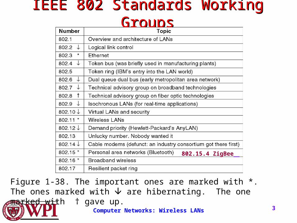
IEEE 802 Standards Working IEEE 802 Standards Working GroupsGroups
Figure 1-38. The important ones are marked with *. The ones marked with are hibernating. The one marked with † gave up.
802.15.4 ZigBee
Computer Networks: Wireless LANs 4
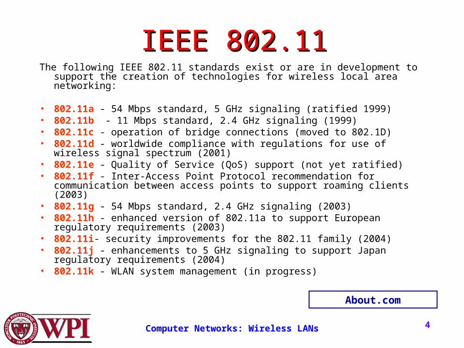
IEEE 802.11IEEE 802.11The following IEEE 802.11 standards exist or are in development to support the creation
of technologies for wireless local area networking:
• 802.11a - 54 Mbps standard, 5 GHz signaling (ratified 1999) • 802.11b - 11 Mbps standard, 2.4 GHz signaling (1999) • 802.11c - operation of bridge connections (moved to 802.1D) • 802.11d - worldwide compliance with regulations for use of wireless signal spectrum
(2001) • 802.11e - Quality of Service (QoS) support (not yet ratified) • 802.11f - Inter-Access Point Protocol recommendation for communication between
access points to support roaming clients (2003) • 802.11g - 54 Mbps standard, 2.4 GHz signaling (2003) • 802.11h - enhanced version of 802.11a to support European regulatory requirements
(2003) • 802.11i- security improvements for the 802.11 family (2004) • 802.11j - enhancements to 5 GHz signaling to support Japan regulatory requirements
(2004) • 802.11k - WLAN system management (in progress)
About.com
Computer Networks: Wireless LANs 5
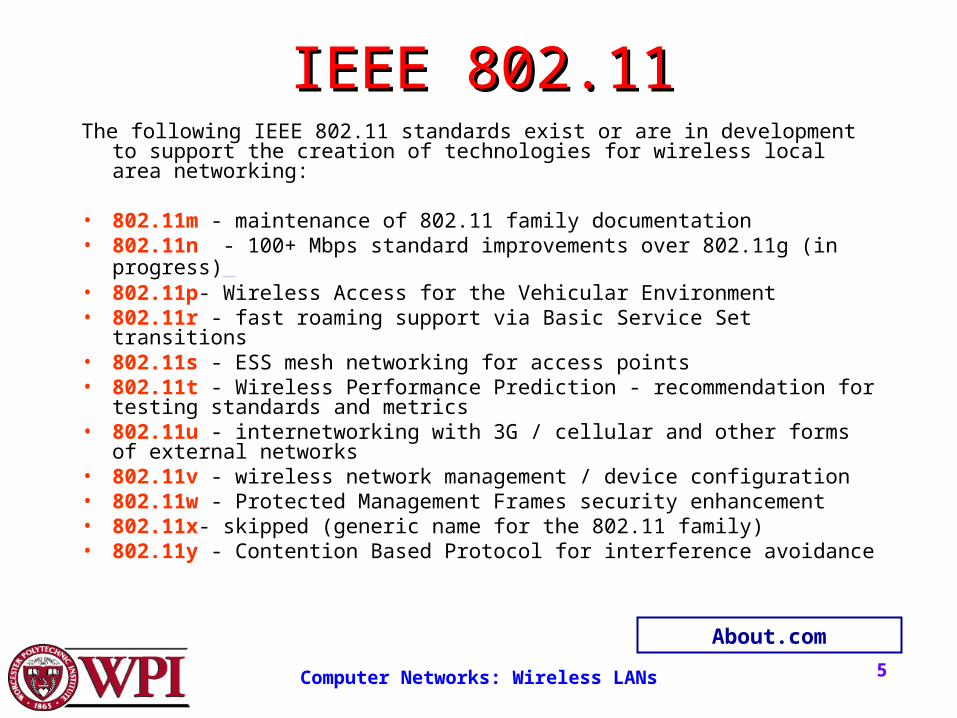
IEEE 802.11IEEE 802.11The following IEEE 802.11 standards exist or are in development to support the
creation of technologies for wireless local area networking:
• 802.11m - maintenance of 802.11 family documentation • 802.11n - 100+ Mbps standard improvements over 802.11g (in progress) • 802.11p- Wireless Access for the Vehicular Environment • 802.11r - fast roaming support via Basic Service Set transitions • 802.11s - ESS mesh networking for access points • 802.11t - Wireless Performance Prediction - recommendation for testing
standards and metrics • 802.11u - internetworking with 3G / cellular and other forms of external
networks • 802.11v - wireless network management / device configuration • 802.11w - Protected Management Frames security enhancement • 802.11x- skipped (generic name for the 802.11 family) • 802.11y - Contention Based Protocol for interference avoidance
About.com
Computer Networks: Wireless LANs 6
Classification of Wireless Classification of Wireless NetworksNetworks
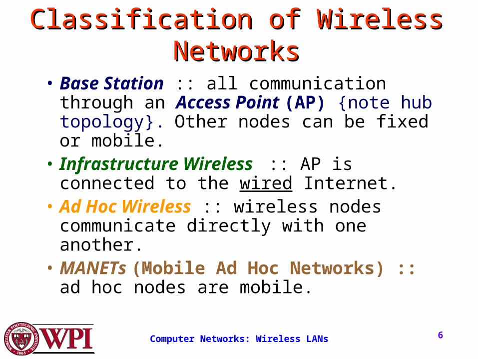
• Base Station :: all communication through an Access Point (AP) {note hub topology}. Other nodes can be fixed or mobile.
• Infrastructure Wireless :: AP is connected to the wired Internet.
• Ad Hoc Wireless :: wireless nodes communicate directly with one another.
• MANETs (Mobile Ad Hoc Networks) :: ad hoc nodes are mobile.
Computer Networks: Wireless LANs 7
Wireless LANsWireless LANs
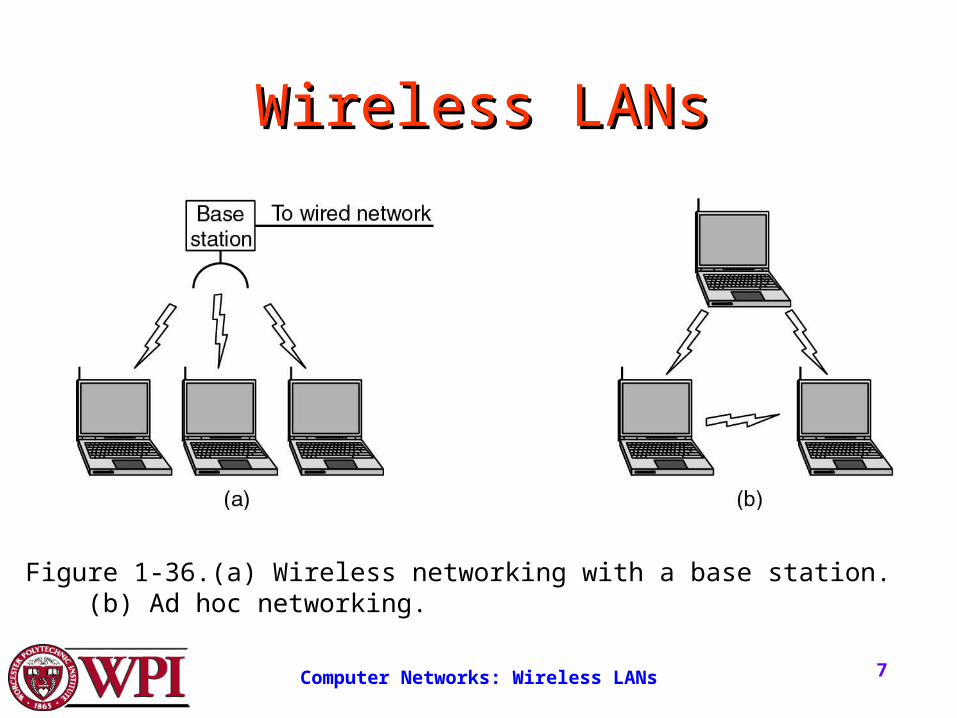
Figure 1-36.(a) Wireless networking with a base station. (b) Ad hoc networking.
Computer Networks: Wireless LANs 8
The 802.11 Protocol StackThe 802.11 Protocol Stack
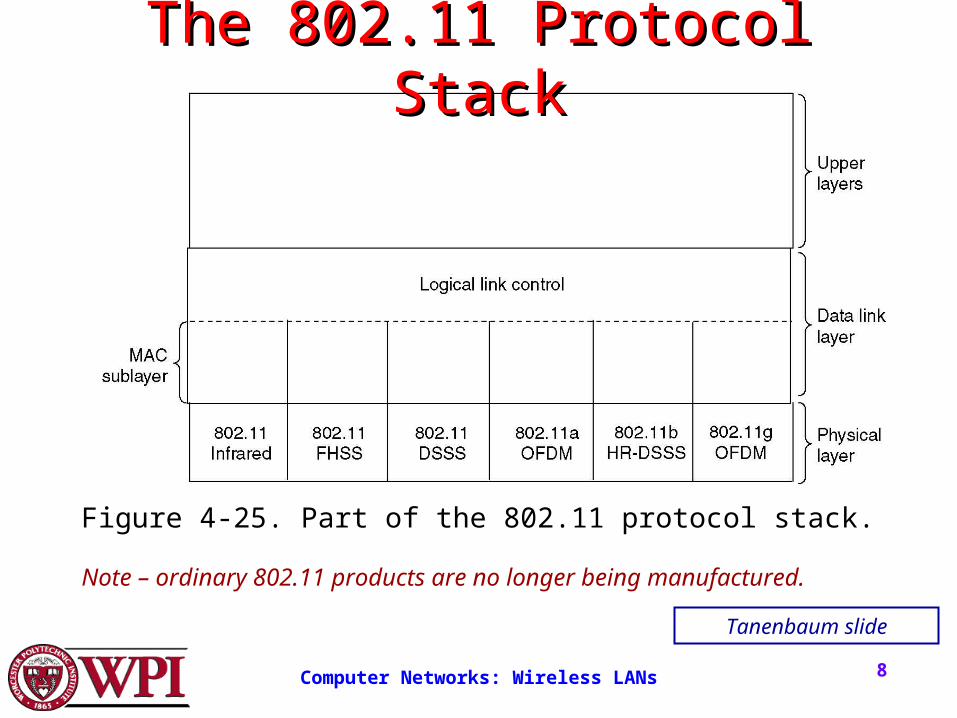
Note – ordinary 802.11 products are no longer being manufactured.
Figure 4-25. Part of the 802.11 protocol stack.
Tanenbaum slide
Computer Networks: Wireless LANs 9
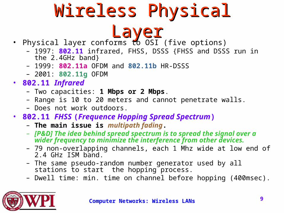
Wireless Physical Layer Wireless Physical Layer • Physical layer conforms to OSI (five options)
– 1997: 802.11 infrared, FHSS, DSSS {FHSS and DSSS run in the 2.4GHz band}– 1999: 802.11a OFDM and 802.11b HR-DSSS– 2001: 802.11g OFDM
• 802.11 Infrared– Two capacities: 1 Mbps or 2 Mbps.– Range is 10 to 20 meters and cannot penetrate walls.– Does not work outdoors.
• 802.11 FHSS (Frequence Hopping Spread Spectrum)– The main issue is multipath fading.– [P&D] The idea behind spread spectrum is to spread the signal over a wider
frequency to minimize the interference from other devices. – 79 non-overlapping channels, each 1 Mhz wide at low end of 2.4 GHz ISM band.– The same pseudo-random number generator used by all stations to start the
hopping process.– Dwell time: min. time on channel before hopping (400msec).
Computer Networks: Wireless LANs 10
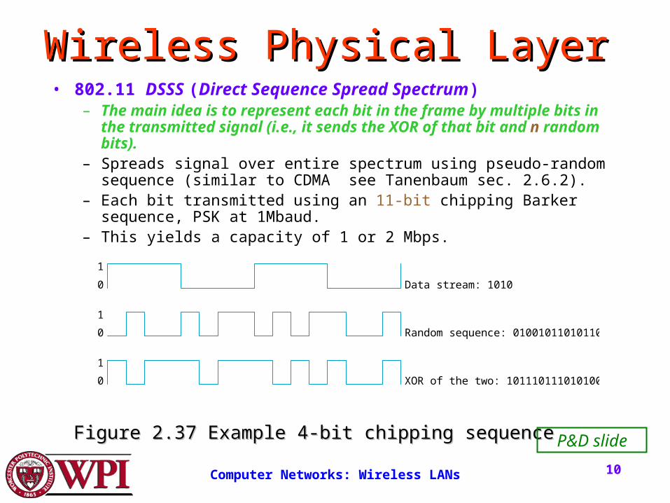
Wireless Physical Layer Wireless Physical Layer • 802.11 DSSS (Direct Sequence Spread Spectrum)
– The main idea is to represent each bit in the frame by multiple bits in the transmitted signal (i.e., it sends the XOR of that bit and n random bits).
– Spreads signal over entire spectrum using pseudo-random sequence (similar to CDMA see Tanenbaum sec. 2.6.2).
– Each bit transmitted using an 11-bit chipping Barker sequence, PSK at 1Mbaud.
– This yields a capacity of 1 or 2 Mbps.
Random sequence: 0100101101011001
Data stream: 1010
XOR of the two: 1011101110101001
0
0
0
1
1
1
Figure 2.37 Example 4-bit chipping sequenceFigure 2.37 Example 4-bit chipping sequence P&D slide
Computer Networks: Wireless LANs 11
Wireless Physical Layer Wireless Physical Layer • 802.11a OFDM (Orthogonal Frequency Divisional
Multiplexing)– Compatible with European HiperLan2.– 54 Mbps in wider 5.5 GHz band transmission range is
limited.– Uses 52 FDM channels (48 for data; 4 for synchronization).– Encoding is complex ( PSM up to 18 Mbps and QAM above this
capacity).– E.g., at 54 Mbps 216 data bits encoded into into 288-bit
symbols.– More difficulty penetrating walls.
Computer Networks: Wireless LANs 12
Wireless Physical Layer Wireless Physical Layer • 802.11b HR-DSSS (High Rate Direct Sequence Spread
Spectrum)– 11a and 11b shows a split in the standards committee.– 11b approved and hit the market before 11a.– Up to 11 Mbps in 2.4 GHz band using 11 million chips/sec.– Note in this bandwidth all these protocols have to deal with
interference from microwave ovens, cordless phones and garage door openers.
– Range is 7 times greater than 11a.– 11b and 11a are incompatible!!
Computer Networks: Wireless LANs 13
Wireless Physical Layer Wireless Physical Layer • 802.11g OFDM(Orthogonal Frequency Division
Multiplexing)– An attempt to combine the best of both 802.11a and
802.11b.
– Supports bandwidths up to 54 Mbps.
– Uses 2.4 GHz frequency for greater range.
– Is backward compatible with 802.11b.
Computer Networks: Wireless LANs 14
802.11 MAC Sublayer 802.11 MAC Sublayer ProtocolProtocol
• In 802.11 wireless LANs, “seizing the channel” does not exist as in 802.3 wired Ethernet.
• Two additional problems:– Hidden Terminal Problem– Exposed Station Problem
• To deal with these two problems 802.11 supports two modes of operation:– DCF (Distributed Coordination Function)– PCF (Point Coordination Function).
• All implementations must support DCF, but PCF is optional.
Computer Networks: Wireless LANs 15
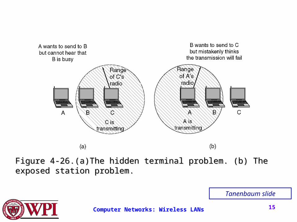
Figure 4-26.(a)The hidden terminal problem. (b) The exposed Figure 4-26.(a)The hidden terminal problem. (b) The exposed station problem.station problem.
Tanenbaum slide
Computer Networks: Wireless LANs 16
The Hidden Terminal ProblemThe Hidden Terminal Problem
• Wireless stations have transmission ranges and not all stations are within radio range of each other.
• Simple CSMA will not work!• C transmits to B.• If A “senses” the channel, it will not hear
C’s transmission and falsely conclude that A can begin a transmission to B.
Computer Networks: Wireless LANs 17
The Exposed Station ProblemThe Exposed Station Problem
• This is the inverse problem.
• B wants to send to C and listens to the channel.
• When B hears A’s transmission, B falsely assumes that it cannot send to C.
Computer Networks: Wireless LANs 18
Distribute Coordination Function Distribute Coordination Function (DCF)(DCF)
• Uses CSMA/CA (CSMA with Collision Avoidance).
– Uses one of two modes of operation:• virtual carrier sensing• physical carrier sensing
• The two methods are supported:1. MACAW (Multiple Access with Collision
Avoidance for Wireless) with virtual carrier sensing.
2. 1-persistent physical carrier sensing.
Computer Networks: Wireless LANs 19
Wireless LAN ProtocolsWireless LAN Protocols[Tan pp.269-270][Tan pp.269-270]
• MACA protocol solved hidden and exposed terminal problems:– Sender broadcasts a Request-to-Send (RTS) and the
intended receiver sends a Clear-to-Send (CTS).
– Upon receipt of a CTS, the sender begins transmission of the frame.
– RTS, CTS helps determine who else is in range or busy (Collision Avoidance).
– Can a collision still occur?
Computer Networks: Wireless LANs 20
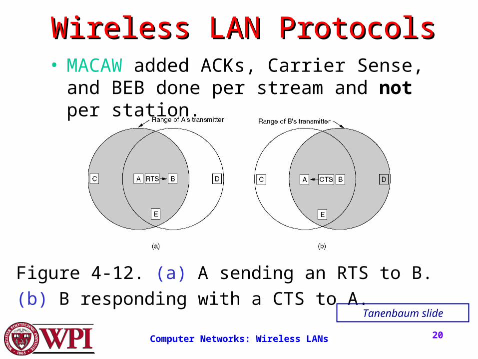
Wireless LAN ProtocolsWireless LAN Protocols
Figure 4-12. (a) A sending an RTS to B.
(b) B responding with a CTS to A.
• MACAW added ACKs, Carrier Sense, and BEB done per stream and not per station.
Tanenbaum slide
Computer Networks: Wireless LANs 21
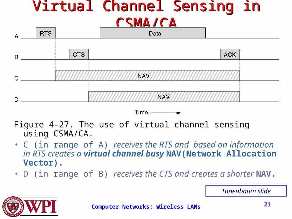
Virtual Channel Sensing in Virtual Channel Sensing in CSMA/CACSMA/CA
Figure 4-27. The use of virtual channel sensing using CSMA/CA.• C (in range of A) receives the RTS and based on information in
RTS creates a virtual channel busy NAV(Network Allocation Vector).
• D (in range of B) receives the CTS and creates a shorter NAV.
Tanenbaum slide
Computer Networks: Wireless LANs 22
Virtual Channel Sensing in Virtual Channel Sensing in CSMA/CACSMA/CA
What is the advantage of RTS/CTS?RTS is 20 bytes, and CTS is 14 bytes.
MPDU can be 2300 bytes.• “virtual” implies source station sets the
duration field in data frame or in RTS and CTS frames.
• Stations then adjust their NAV accordingly!
Computer Networks: Wireless LANs 23
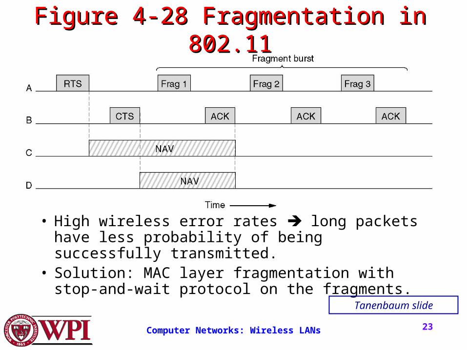
Figure 4-28 Fragmentation in Figure 4-28 Fragmentation in 802.11802.11
• High wireless error rates long packets have less probability of being successfully transmitted.
• Solution: MAC layer fragmentation with stop-and-wait protocol on the fragments.
Tanenbaum slide
Computer Networks: Wireless LANs 24
1-Persistent Physical Carrier Sensing1-Persistent Physical Carrier Sensing • The station senses the channel when it wants to
send.• If idle, the station transmits.
– A station does not sense the channel while transmitting.
• If the channel is busy, the station defers until idle and then transmits (1-persistent).
• Upon collision, wait a random time using binary exponential backoff (BEB).
Computer Networks: Wireless LANs 25
Point Coordinated Function (PCF)Point Coordinated Function (PCF)
• PCF uses a base station to poll other stations to see if they have frames to send.
• No collisions occur.
• Base station sends beacon frame periodically.
• Base station can tell another station to sleep to save on batteries and base stations holds frames for sleeping station.
Computer Networks: Wireless LANs 26
DCF and PCF Co-ExistenceDCF and PCF Co-Existence• Distributed and centralized control can co-exist using
InterFrame Spacing.• SIFS (Short IFS) :: is the time waited between packets
in an ongoing dialog (RTS,CTS,data, ACK, next frame)
• PIFS (PCF IFS) :: when no SIFS response, base station can issue beacon or poll.
• DIFS (DCF IFS) :: when no PIFS, any station can attempt to acquire the channel.
• EIFS (Extended IFS) :: lowest priority interval used to report bad or unknown frame.
Computer Networks: Wireless LANs 27
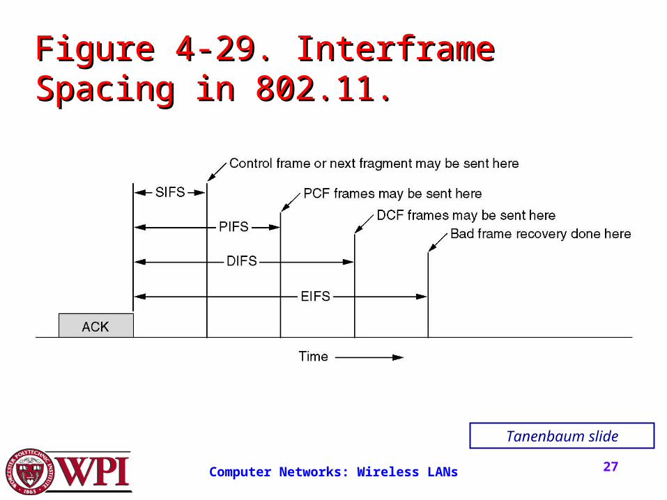
Figure 4-29. Interframe Spacing in Figure 4-29. Interframe Spacing in 802.11.802.11.
Tanenbaum slide
Computer Networks: Wireless LANs 28
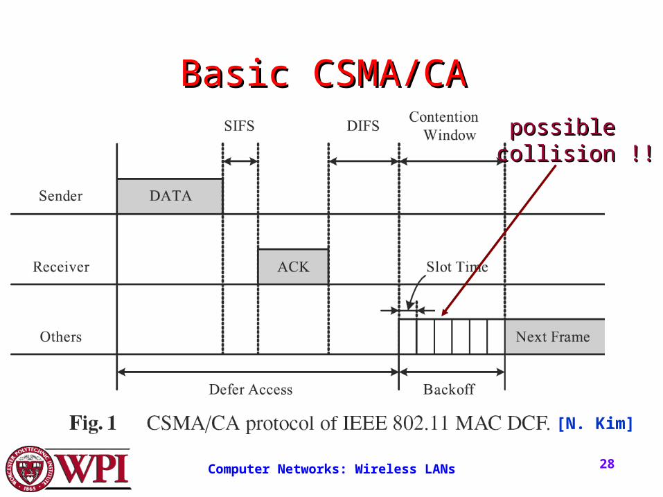
Basic CSMA/CABasic CSMA/CA
[N. Kim]
possiblepossible collision !!collision !!
Computer Networks: Wireless LANs 29
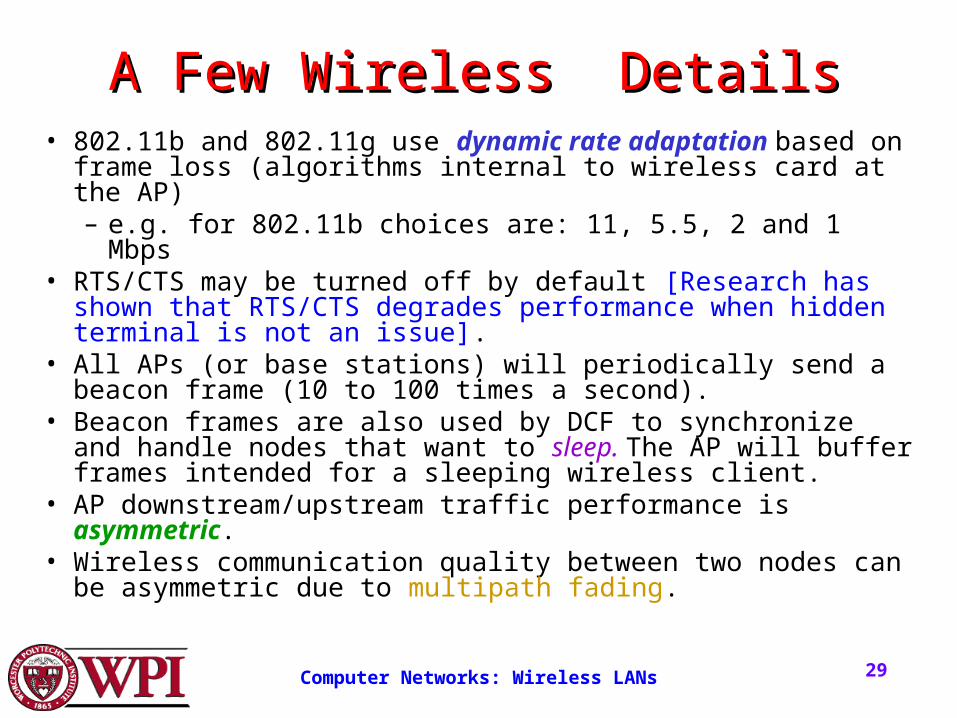
A Few Wireless DetailsA Few Wireless Details• 802.11b and 802.11g use dynamic rate adaptation based on
frame loss (algorithms internal to wireless card at the AP)– e.g. for 802.11b choices are: 11, 5.5, 2 and 1 Mbps
• RTS/CTS may be turned off by default [Research has shown that RTS/CTS degrades performance when hidden terminal is not an issue].
• All APs (or base stations) will periodically send a beacon frame (10 to 100 times a second).
• Beacon frames are also used by DCF to synchronize and handle nodes that want to sleep. The AP will buffer frames intended for a sleeping wireless client.
• AP downstream/upstream traffic performance is asymmetric.• Wireless communication quality between two nodes can be
asymmetric due to multipath fading.
Computer Networks: Wireless LANs 3030303030
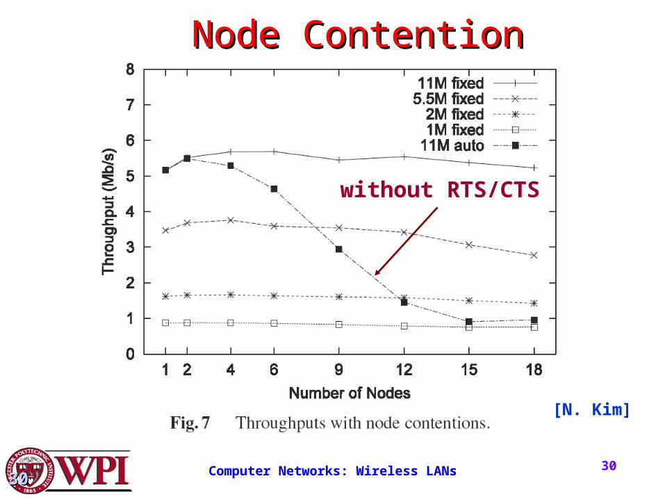
Node ContentionNode Contention
[N. Kim]
without RTS/CTS
Computer Networks: Wireless LANs 3131313131
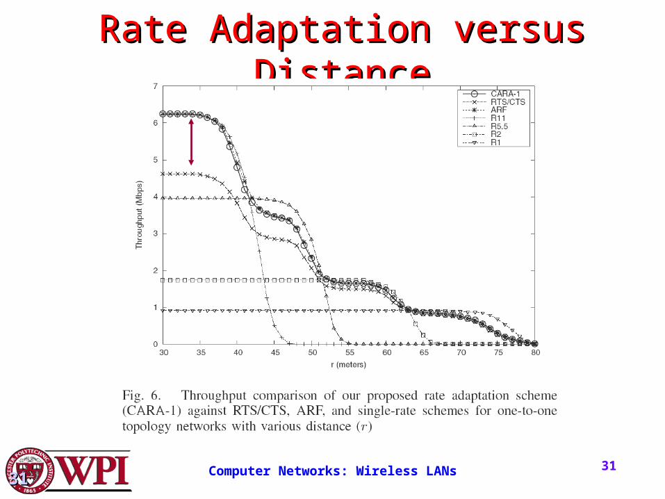
Rate Adaptation versus DistanceRate Adaptation versus Distance
Computer Networks: Wireless LANs 32
Wireless Sensor NetworksWireless Sensor Networks• Sensors – small devices with low-power transmissions
and energy limitations (e.g., battery lifetime is often a BIG concern.)
• The main distinction from traditional wireless networks is that the data traffic originates at the sensor node and is sent upstream towards the access point (AP) or base station that collects the data.
• While the nature of data collection at the sensor is likely to be event driven, for robustness, the generation of sensor packets should be periodic if possible.
Computer Networks: Wireless LANs 33
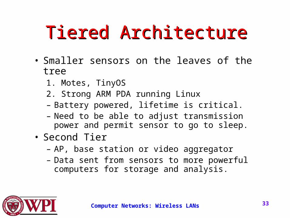
Tiered ArchitectureTiered Architecture
• Smaller sensors on the leaves of the tree 1. Motes, TinyOS2. Strong ARM PDA running Linux– Battery powered, lifetime is critical.– Need to be able to adjust transmission power and
permit sensor to go to sleep.
• Second Tier– AP, base station or video aggregator– Data sent from sensors to more powerful
computers for storage and analysis.
Computer Networks: Wireless LANs 34
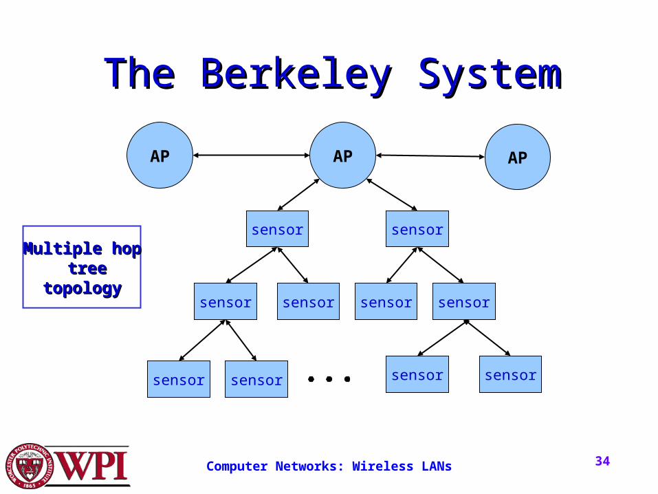
The Berkeley SystemThe Berkeley System
AP AP AP
sensor
sensor sensor sensor
sensor sensor
sensor
sensor
sensor sensor
Multiple hopMultiple hop treetree
topologytopology
Computer Networks: Wireless LANs 35
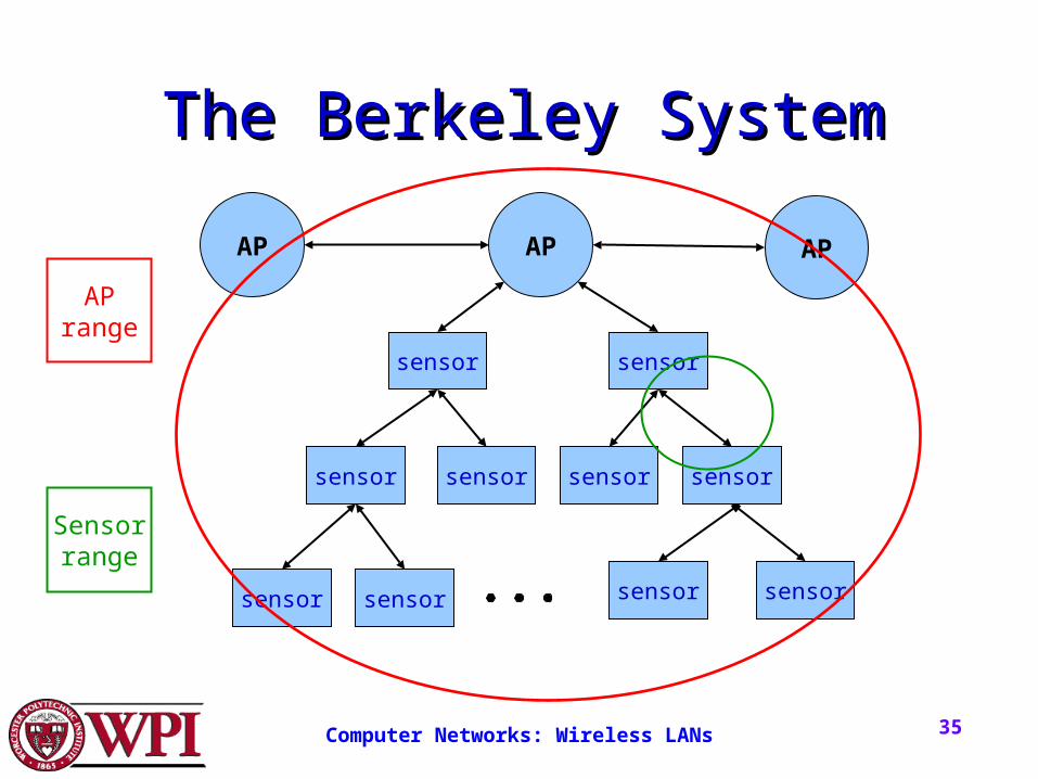
The Berkeley SystemThe Berkeley System
AP AP AP
sensor
sensor sensor sensor
sensor sensor
sensor
sensor
sensor sensor
APrange
Sensorrange
Top Related