

![Recent Advances in Composites of Graphene and …...Recent Advances in Composites of Graphene and Layered Double Hydroxides for Water Remediation:AReview HongweiPang,[a, b] Yihan Wu,[a]](https://static.fdocuments.in/doc/165x107/5f02e66b7e708231d4069139/recent-advances-in-composites-of-graphene-and-recent-advances-in-composites.jpg)


Languages
Pages
Legal

Nano Res
1
Nano Research DOI 10.1007/s12274‐014‐0463‐6
Composites of Graphene and Encapsulated Silicon for Practically Viable High-Performance Lithium-Ion Batteries
Xin Zhao*, Minjie Li, Kuo-Hsin Chang, Yu-Ming Lin*
Nano Res., Just Accepted Manuscript • DOI: 10.1007/s12274-014-0463-6 http://www.thenanoresearch.com on April 1, 2014 © Tsinghua University Press 2014
Just Accepted This is a “Just Accepted” manuscript, which has been examined by the peer‐review process and has been accepted for publication. A “Just Accepted” manuscript is published online shortly after its acceptance, which is prior to technical editing and formatting and author proofing. Tsinghua University Press (TUP) provides “Just Accepted” as an optional and free service which allows authors to make their results available to the research community as soon as possible after acceptance. After a manuscript has been technically edited and formatted, it will be removed from the “Just Accepted” Web site and published as an ASAP article. Please note that technical editing may introduce minor changes to the manuscript text and/or graphics which may affect the content, and all legal disclaimers that apply to the journal pertain. In no event shall TUP be held responsible for errors or consequences arising from the use of any information contained in these “Just Accepted” manuscripts. To cite this manuscript please use its Digital Object Identifier (DOI®), which is identical for all formats of publication.

1
Graphical Table of Contents
By encapsulating silicon particles via in-situ polymerization and carbonization of
phloroglucinol-formaldehyde gel, followed by incorporation of graphene sheets, a high-
performance Si composite anode was demonstrated in half cell and full cell configurations,
yielding remarkably enhanced capacity and stability for advanced lithium-ion batteries.
Create PDF files without this message by purchasing novaPDF printer (http://www.novapdf.com)

2
Composites of Graphene and Encapsulated Silicon for Practically
Viable High-Performance Lithium-Ion Batteries
Xin Zhao*, Minjie Li, Kuo-Hsin Chang, Yu-Ming Lin*
Bluestone Global Tech, 169 Myers Corners Road, Wappingers Falls, NY 12590, USA.
E-mail: [email protected], [email protected]
Abstract
A facile and scalable approach to synthesize silicon composite anode was developed by
encapsulating Si particles via in-situ polymerization and carbonization of phloroglucinol-
formaldehyde gel, followed by incorporation of graphene nanoplatelets. Attributed to the
improved structural integrity, a high packing density and an intimate electrical contact
consolidated by the conductive networks, the composite anode yielded remarkably enhanced
electrochemical performance in terms of charge storage capability, cycling life and coulombic
efficiency. A half cell achieved reversible capacities of 1600 mAh g-1 and 1000 mAh g-1 at 0.5 A
g-1 and 2.1 A g-1, respectively, while retaining more than 70% of the initial capacities over 1000
cycles. Complete lithium-ion pouch cells coupling such anode with lithium metal oxide cathode
demonstrated superior cycling performance and energy output, representing significant advance
in developing Si-based electrode practically applicable to high-performance lithium-ion batteries.
Keywords: Silicon nanoparticles, graphene nanoplatelets, phloroglucinol-formaldehyde gel,
lithium-ion batteries
Create PDF files without this message by purchasing novaPDF printer (http://www.novapdf.com)

3
1 Introduction
The pressing need for advanced battery technologies has accelerated innovation of electrode
formulations to replace conventional intercalation compounds and graphitic materials used in
cathode and anode, respectively, in lithium-ion batteries. Among any known anode materials,
silicon demonstrates the highest gravimetric capacity of 3579 mAh g-1, attributed to the
formation of an alloy composition of Li15Si4 via electrochemical lithiation of Si at room
temperature [1-4]. However, the practical implementation of Si-based anode is notoriously
impeded by its massive volumetric expansion/contraction and subsequent structural pulverization,
as well as the overall swelling in a practical cell format. Besides, electrolyte decomposition at the
freshly formed Si/electrolyte interface along with continual formation of side-reaction products
gradually depletes the available Li ions and isolates the electrode fragments, which severely
hinders the rate capability, deep cycling ability and lifespan of Si-based anode [5-8].
In order to overcome mechanical cracking or fracture during cycling, it is usually necessary to
reduce the particle size of Si, while the potential of nano-sized Si to be fully adopted in
commercial entities is largely sacrificed consequential of reduced tap density and low areal mass
loading [9-11]. Incorporating carbonaceous species into Si offers an alternative solution to
suppress the detrimental effects of volumetric variation and improve the electrical continuity.
However, conformal carbon coatings on Si would rapture readily upon swelling and re-expose it
to side-product deposition [12-14]. Conductive polymers and carbon nanostructures, in particular
carbon nanotubes and their derivatives, provide flexible backbones to better accommodate the Li
ion insertion/extraction stress when introduced into Si anode [15-19]. Nevertheless, the
inherently high surface energy of Si nanoparticles is conducive to electrochemical sintering,
leaving the long-term cycling stability and inferior coulombic efficiency unresolved [20, 21]; the
Create PDF files without this message by purchasing novaPDF printer (http://www.novapdf.com)

4
high surface carbonaceous materials further compromises the coulombic efficiency due to the
formation and propagation of solid electrolyte interphase (SEI), and prevents the high-capacity
anode from being viable when paired with cathodes in full cell formats [9, 22]. As the material
loading increases, the primary Si particles located near the center of large aggregates become
separated from the conductive components, leading to fatal deterioration of overall performance.
Thus until now, there is still a lack of transformative Si anode development and full cell designs
that are compatible with commercial configurations and high-throughput manufacturing
protocols.
Here we report a high-performance Si composite anode constructed from carbon gel sheathed Si
particles and graphene building blocks by a facile and scalable synthetic approach. The Si
particles were encapsulated by a uniform carbonized phloroglucinol- formaldehyde (PF) gel and
enveloped in a graphene platelet matrix (Fig. 1a), which confers a combination of advantageous
features: (1) an intimate electrical contact assured by the carbonaceous networks; (2) a restrained
structural damage and irreversible capacity loss warranted by the SiOx/carbon coating and
graphene sheets in contrast to rigid carbon shells and conventional carbon additives [12, 13, 23];
and (3) a high packing density and sustained structural integrity enabled by the compact graphitic
domains [24, 25]. These synergetic functions afforded superior rate capability, cycling life and
improved volumetric capacity. Proceeded by tape casting and coupling with a formulated lithium
metal oxide cathode, the Si composite anode displayed enhanced performance at practically
viable high mass loading in full cell formats.
2 Experimental
Create PDF files without this message by purchasing novaPDF printer (http://www.novapdf.com)

5
2.1 Synthesis of PF gel encapsulated Si particles
Si powders (~100 nm, Alfa Aesar) were removed from argon environment and exposed to air
overnight. In a typical run, 0.25 g phloroglucinol (Sigma-Aldrich) was dispersed in 5 mL DDI
water under vigorous stirring, followed by dropwise addition of 0.02 g concentrated hydrochloric
acid. 0.73 g Si particles were poured into the suspension, and after stirring at room temperature
for 30 min, 0.26 g 37% formaldehyde aqueous solution (Sigma-Aldrich) was added in. The
mixture was kept at room temperature under stirring until a viscous gel-like structure was
formed. The mixture was vacuum-dried at 70 ºC for overnight, and then calcined at 800 ºC for
2.5 h under a flow of Ar (100 mL min-1).
2.2 Characterization
Sample morphology was investigated using JEOL JSM-7001 scanning electron microscopy and
JEOL JEM-2100F transmission electron microscopy. X-ray diffraction patterns were collected
by a Bruker AXS Gmbh diffractometer with CuK radiation (=1.5418 Å) at 30 kV/10 mA, a
scan rate of 4o min-1. Raman spectra were recorded on a WiTec alpha500 automated confocal
Raman microscope at 532 nm laser excitation. Thermogravimetric analysis was performed by
heating the samples to 800ºC at the rate of 10ºC min-1 in flowing air. The weight loss, after
correcting for oxidation of Si, was used to calculate the carbon fraction. Surface area was
determined from N2 adsorption/desorption isotherm at 77K, collected using Micromeritics ASAP
2000 and analyzed using Brunauer-Emmett-Teller (BET) method.
2.3 Electrochemical measurement
The anode film was fabricated by pasting a slurry containing PF-Si particles, graphene
nanoplatelets (XG Sciences), and poly(acrylic acid) (Sigma-Aldrich) with a weight ratio of 6:3:1
Create PDF files without this message by purchasing novaPDF printer (http://www.novapdf.com)
6
onto a copper foil. The typical mass loading was of the order of 1-4 mg cm-2. The electrode was
dried at 90 ºC under vacuum for overnight, and compressed at 10 MPa before being assembled
into a cell.
Charge/discharge tests versus lithium were carried out using a CR2032-type coin cell. The cells
were assembled in an argon-filled glove box, using a metallic lithium disc as the counter
electrode and a Whatman GF/F microporous borosilicate glass-fiber membrane as the separator.
The electrolyte solution was 1 M LiPF6 in ethylene carbonate/dimethyl carbonate (EC/DMC 1:1
by volume, BASF) plus 10 vol% fluoroethylene carbonate additive. Galvanostatic
charge/discharge measurements were conducted with a Maccor Series 4000 automated test
system at various current densities in the voltage range of 0.02-1.5 V vs. Li/Li+. Electrochemical
impedance spectroscopy (EIS) measurements were conducted using an Ametak VersaSTAT3
potentiostat/galvanostat by applying an AC voltage of 10 mV amplitude and DC open circuit
voltage (OCV) in the frequency range of 1 MHz-0.01 Hz at room temperature. Theoretical
capacity of composite anode is calculated as 3500 mAh g-1 × 60% (Si wt-%) = 2100 mAh g-1
(1C=2.1 A g-1).
For full cell assembly, a lithium nickel cobalt manganese oxide (NMC) cathode was fabricated
by pasting a mixture of LiNi0.5Co0.2Mn0.3O2 powders (Toda America), carbon black (Super C45,
Timcal) and poly(vinylidene fluoride) (Arkema) with a weight ratio of 86:6:8 onto an aluminum
foil. The cathode mass loading was 8.5-20 mg cm-2 and the anode mass loading was 1-3.6 mg
cm-2 on single side. The pair of electrodes was isolated by a Celgard 2325 trilayer separator and
sealed inside an aluminum laminated pouch. The pouch cell was cycled at a constant rate of 0.5C
in the voltage range of 3-4.1 V.
Create PDF files without this message by purchasing novaPDF printer (http://www.novapdf.com)
7
3 Results and discussion
Carbon encapsulated Si particles were fabricated by carbonizing 100 nm-sized Si powders
bonded to phloroglucinol-formaldehyde (PF) gel. The mixture of phloroglucinol and
formaldehyde monomers was selected as an inexpensive carbonaceous precursor, as it undergoes
polymerization under less stringent processing conditions relative to other phenolic resin
monomers [26]. Specifically, Si particles were exposed to air to ensure formation of a stable
hydrophilic oxide layer. The particles were dispersed directly in an aqueous suspension of
phloroglucinol by sonication, and polymerization was completed within three hours at room
temperature, converting the mixture to a gel after addition of formaldehyde in the presence of
hydrochloric acid. The oxide passivation layer was expected to facilitate the dispersing of Si
particles and anchoring of the hydroxyl groups of phloroglucinol to the surface of Si (Fig. 1b) via
a hydrogen-bonding interaction, creating homogeneous tethering to the Si particles and
preventing their sintering into bulk agglomerates.
The PF gel was carbonized in an inert atmosphere at 800 ºC, and tuning of the Si content was
achieved by varying the weight ratio of Si and PF polymer precursors. PF-Si composites with
three different Si contents were prepared, denoted as PF-Si-1, PF-Si-2, and PF-Si-3, with the Si
content of 78%, 83%, and 86%, respectively, as determined by weight losses upon combustion of
the carbon layer in thermogravimetric analysis (Fig. S1 in the ESM). Transmission electron
microscopy (TEM) images confirmed the encapsulation of Si particles with an amorphous and
continuous layer that was ca. 10 nm thick (Fig. 2a and b). The presence of native SiOx was
observed in pristine Si particles [24] and verified by the energy dispersive X-ray (EDX) spectra
Create PDF files without this message by purchasing novaPDF printer (http://www.novapdf.com)

8
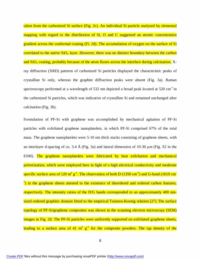
taken from the carbonized Si surface (Fig. 2c). An individual Si particle analyzed by elemental
mapping with regard to the distribution of Si, O and C suggested an atomic concentration
gradient across the conformal coating (Fi. 2d). The accumulation of oxygen on the surface of Si
correlated to the native SiOx layer. However, there was no distinct boundary between the carbon
and SiOx coating, probably because of the atom fluxes across the interface during calcination. X-
ray diffraction (XRD) patterns of carbonized Si particles displayed the characteristic peaks of
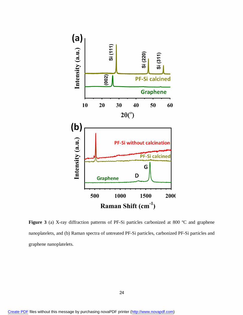
crystalline Si only, whereas the graphite diffraction peaks were absent (Fig. 3a). Raman
spectroscopy performed at a wavelength of 532 nm depicted a broad peak located at 520 cm-1 in
the carbonized Si particles, which was indicative of crystalline Si and remained unchanged after
calcination (Fig. 3b).
Formulation of PF-Si with graphene was accomplished by mechanical agitation of PF-Si
particles with exfoliated graphene nanoplatelets, in which PF-Si comprised 67% of the total
mass. The graphene nanoplatelets were 5-10 nm thick stacks consisting of graphene sheets, with
an interlayer d-spacing of ca. 3.4 Å (Fig. 3a) and lateral dimension of 10-30 m (Fig. S2 in the
ESM). The graphene nanoplatelets were fabricated by heat exfoliation and mechanical
pulverization, which were employed here in light of a high electrical conductivity and moderate
specific surface area of 120 m2 g-1. The observation of both D (1350 cm-1) and G-band (1610 cm-
1) in the graphene sheets attested to the existence of disordered and ordered carbon features,
respectively. The intensity ratios of the D/G bands corresponded to an approximately 400 nm-
sized ordered graphitic domain fitted to the empirical Tuinstra-Koenig relation [27]. The surface
topology of PF-Si/graphene composites was shown in the scanning electron microscopy (SEM)
images in Fig. 2d. The PF-Si particles were uniformly supported on exfoliated graphene sheets,
leading to a surface area of 41 m2 g-1 for the composite powders. The tap density of the
Create PDF files without this message by purchasing novaPDF printer (http://www.novapdf.com)
9
composite was as high as 1.1 g cm-3, which is very close to that of conventional graphite and
outperforms many other Si/carbon systems, such as recently reported hierarchical (0.49 g cm-3)
[28] or micron-sized (0.78 g cm-3) [10] Si/carbon granules.
The electrochemical performance of pristine Si particles and PF-Si/graphene composites was
evaluated using deep charge/discharge galvanostatic cycling between 1.5-0.02 V (vs. Li/Li+) in a
half-cell setup with Li metal foils as the counter electrode. The first charge/discharge voltage
profile of PF-Si/graphene composites exhibited an extended plateau at ca. 0.1 V, corresponding
to the phase transformation from crystalline Si to lithium silicide (Fig. S3 in the ESM) [29]. A
coulombic efficiency of 70% was obtained for the first cycle. The irreversible capacity loss was
attributed to initial solid electrolyte interphase (SEI) formation, and reactions of Li ions with the
SiOx layer and residual functional groups on the carbon surfaces [30]. The relatively low surface
area of graphene nanoplatelets was beneficial in depressing the SEI growth and thus preserving
electrical contact over cycling, compared to chemical exfoliated and graphene oxide (GO)-
derived graphene [31-34]. It has been suggested that the SiOx reacts with Li ions, forming
irreversible Li4SiO4 or reversible Li2Si2O5 phases, which further assisted the formation of stable
SEI layer [35-37]. Afterwards, the charge/discharge showed sloping profiles characteristic of
lithiation/delithiation of amorphous Si in two different voltage regions (Fig. 4a and S3 in the
ESM). The coulombic efficiency rapidly increased and stabilized at around 99% after 10 cycles,
which was higher than that of previously studied Si/graphene composite anode [24, 38-41].
When cycled at a constant current density of 0.5 A g-1 (0.25C based on the theoretical capacity),
the composite anode PF-Si-2 with 50 wt% Si loading attained the highest reversible capacity of
approximately 1600 mAh g-1 based on the mass of PF-Si particles (Fig. 4b). The rising of
capacity in the beginning few cycles was ascribed to the inward diffusion of electrolyte
Create PDF files without this message by purchasing novaPDF printer (http://www.novapdf.com)
10
throughout the compact network and increasing of accessible surface area of “pushed out” Si
particles [42]. After 300 full charge/discharge cycles, a coulombic efficiency of 99.5% and the
initial capacity was very well retained without any discernible decline. This was equivalent to a
capacity of 1000 mAh g-1 based on the entire laminate weight when taking the mass of graphene
and binder into account. Attributed to a high packing density, the volumetric capacity of the
entire anode reached 1100 mAh cm-3, almost doubling that of conventional graphitic anode (620
mAh cm-3) [43, 44], and is among the best results for engineered Si anode to date [16, 19, 45-
48]. In comparison, the as-received Si nanoparticles supported on graphene exhibited a first
cycle coulombic efficiency of 30% and lost over 50% of the initial value after only 50 cycles,
while all the encapsulated samples showed drastically improved capacity and stability. The
existence of optimum Si loading can be attributed to a combination of balanced factors such as
electrical and ionic conduction throughout the carbonaceous networks, as well as stress
dissipation and structural integrity.
The superior rate capability facilitated by the continuous conducting network and amorphous
carbon coating was evident when charging/discharging the PF-Si/graphene composite anode at
high rates (Fig. 4c). The reversible capacity of PF-Si-2 composite stabilized at 1100 mAh g-1,
maintaining 68% of the original capacity with increasing the rate from 0.25 A g-1 (C/8) to 2.1 A
g-1 (1C). When switching back to the initial rate, the original capacity was fully recovered. At a
constant rate of 2.1 A g-1, a single charge/discharge cycle took only 15 minutes, while the
capacity fade was as low as < 0.04% per cycle up to 1000 cycles on average (Fig. 4d). The
volumetric capacity remained a quite high value of 730 mAh g-1 after 500 cycles. Despite higher
gravimetric capacities > 2000 mAh g-1 given by various Si nanostructures e.g. Si nanowires [5,
18, 49], nanotubes [13] and hollow spheres or monolithics [7, 14], our composite anode achieved
Create PDF files without this message by purchasing novaPDF printer (http://www.novapdf.com)
11
an unprecedented balance across capacity and retention at high rates and long-term cycling,
which is more competitive than previously reported nanostructured Si-based anode [16-20, 37-
41, 45-48, 50]. Notably, even at a high mass loading of 4 mg cm-2, there was almost no
degradation in the capacity (Fig. S5 in the ESM). Electrochemical impedance spectroscopy (EIS)
further confirmed the improved charge-transfer and Li ion diffusion kinetics of PF-Si particles
compared to pristine Si (Fig. 4e). Both the Ohmic resistance Rs (real impedance at 100 kHz, ~3
) and the charge-transfer resistance Rct (estimated diameter of the semicircle, ~65 ) of the PF-
Si-2/graphene anode were smaller that of the pristine Si/graphene anode (Rs~14 Rct~125
when fitted to the equivalent circuit in the inset of Fig. 4e [51], accompanied with a less
inclined Warburg region for the PF-Si-2/graphene anode contrasting the pristine Si/graphene
anode.
To validate the anode performance in a full cell, the PF-Si-2/graphene anode was coupled with a
NMC cathode and sealed in a laminated pouch with tab leads extending out (Fig. 5). The NMC
was selected via a cathode screening, because of its satisfactory capacity and lifetime, a relative
flat voltage plateau and reasonably high operating potential (Fig. S4 in the ESM). The
insufficient initial coulombic efficiency of the anode film can be tackled by prelithiation prior to
incorporation into the pouch cell battery [52]. The balancing mass ratio of anode (1.2 mg cm-2)
and cathode materials (8.5 mg cm-2) was set as 1:7 by using the total capacity of 1000 mAh g-1
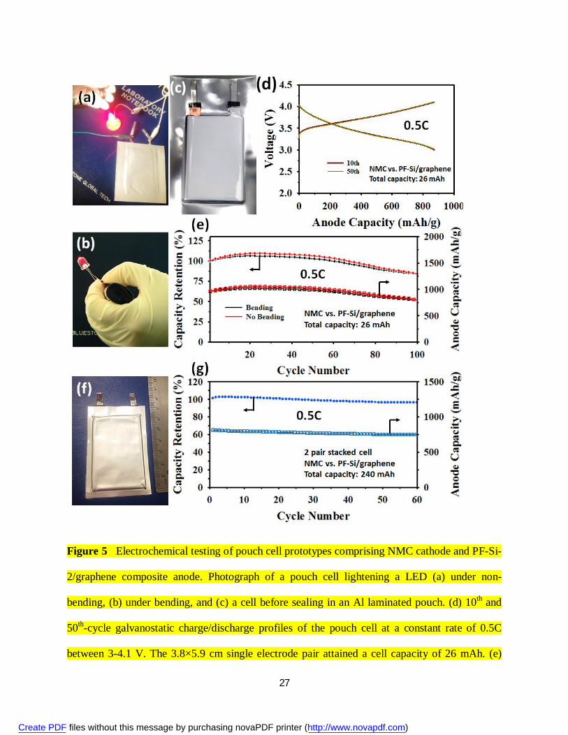
and 140 mAh g-1 for anode and cathode, respectively. When cycled between 3 and 4.1 V at a
constant rate of 0.5C, the cell reversibly charged and discharged with stable capacity retention
close to its designed cell capacity of 1.2 mAh cm-2, showing a potential plateau at around 3.5 V
(Fig. 5d). After 100 cycles, the cell maintained 85% of its initial capacity (Fig. 5e), while
delivering a high gravimetric energy density of 420 Wh kg-1 based upon the total mass of
Create PDF files without this message by purchasing novaPDF printer (http://www.novapdf.com)

12
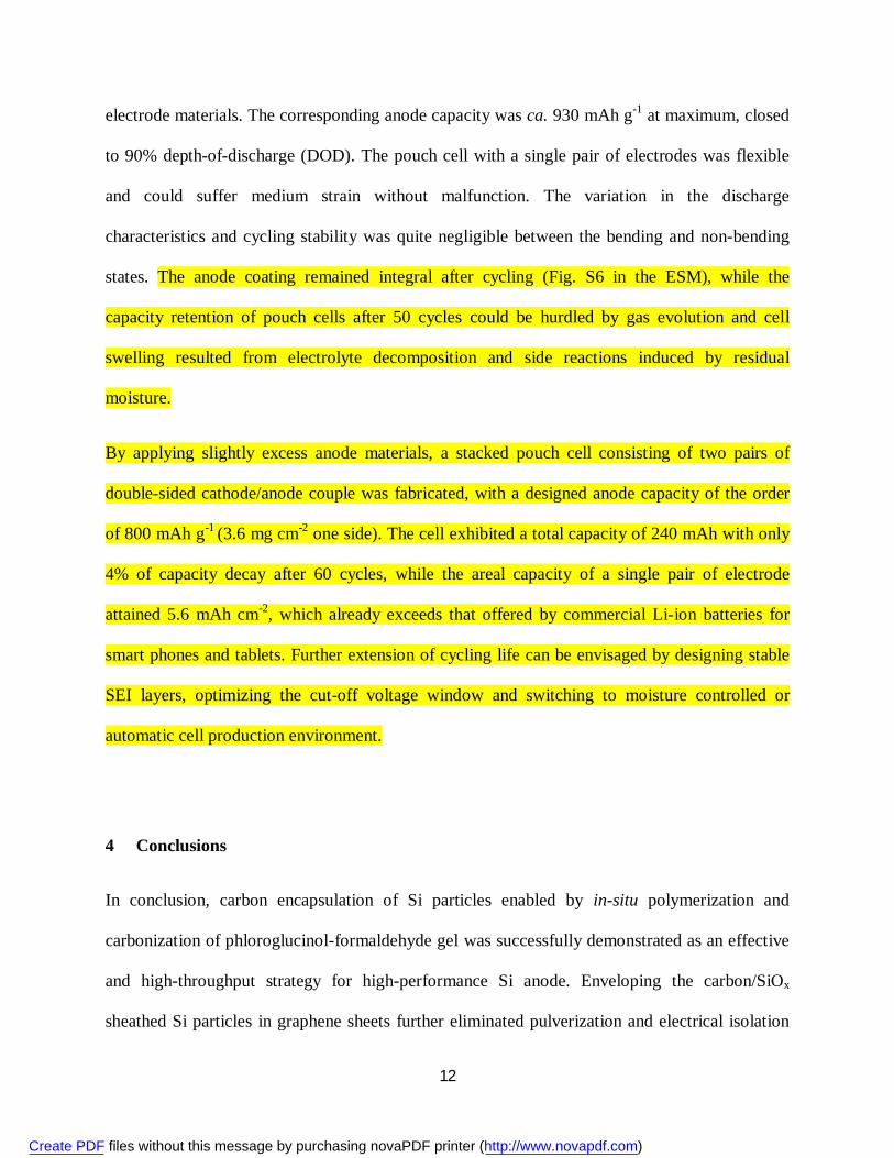
electrode materials. The corresponding anode capacity was ca. 930 mAh g-1 at maximum, closed
to 90% depth-of-discharge (DOD). The pouch cell with a single pair of electrodes was flexible
and could suffer medium strain without malfunction. The variation in the discharge
characteristics and cycling stability was quite negligible between the bending and non-bending
states. The anode coating remained integral after cycling (Fig. S6 in the ESM), while the
capacity retention of pouch cells after 50 cycles could be hurdled by gas evolution and cell
swelling resulted from electrolyte decomposition and side reactions induced by residual
moisture.
By applying slightly excess anode materials, a stacked pouch cell consisting of two pairs of
double-sided cathode/anode couple was fabricated, with a designed anode capacity of the order
of 800 mAh g-1 (3.6 mg cm-2 one side). The cell exhibited a total capacity of 240 mAh with only
4% of capacity decay after 60 cycles, while the areal capacity of a single pair of electrode
attained 5.6 mAh cm-2, which already exceeds that offered by commercial Li-ion batteries for
smart phones and tablets. Further extension of cycling life can be envisaged by designing stable
SEI layers, optimizing the cut-off voltage window and switching to moisture controlled or
automatic cell production environment.
4 Conclusions
In conclusion, carbon encapsulation of Si particles enabled by in-situ polymerization and
carbonization of phloroglucinol-formaldehyde gel was successfully demonstrated as an effective
and high-throughput strategy for high-performance Si anode. Enveloping the carbon/SiOx
sheathed Si particles in graphene sheets further eliminated pulverization and electrical isolation
Create PDF files without this message by purchasing novaPDF printer (http://www.novapdf.com)
13
of active materials, resulting in a composite with excellent gravimetric and volumetric capacity,
rate capability and cyclability. Very significantly, the preparation method employed can be easily
adapted and scaled up to existing high-throughput protocols for electrode and cell manufacture.
As-assembled pouch cell batteries incorporating the composite anode rendered stable energy
outputs and storage capabilities when subjected to long cycling, allowing a promising boost for
the realization of high-performance energy storage devices.
Acknowledgements
The authors acknowledge Dr. Thanasis Georgiou for his assistance on TGA measurement.
Electronic Supplementary Material: Supplementary material is available in the online version of
this article at:
References
[1] Boukamp, B. A.; Lesh, G. C.; Huggins, R. A. All-solid lithium electrodes with mixed-
conductor matrix. J. Electrochem. Soc. 1981, 128, 725-729.
[2] Larcher, D.; Beattie, S.; Morcrette, M.; Edström, K.; Jumas, J.-C.; Tarascon, J.-M. Recent
finds and prospects in the field of pure metals as negative electrodes for Li-ion batteries. J.
Mater. Chem. 2007, 17, 3759-3772.
[3] Obrovac, M. N.; Christensen, L. Structural changes in silicon anodes during lithium
insertion/extraction. Electrochem. Solid-State Lett. 2004, 7, A93–A96.
Create PDF files without this message by purchasing novaPDF printer (http://www.novapdf.com)

14
[4] Key, B.; Bhattacharyya, R.; Morcrette, M.; Seznéc, V.; Tarascon, J.-M.; Grey, C. P. Real-
time NMR investigations of structural changes in silicon electrodes for lithium-ion batteries. J.
Am. Chem. Soc. 2009, 131, 9239-9249.
[5] Chan, C. K.; Peng, H.; Liu, G.; McIlwrath, K.; Zhang, X. F.; Huggins, R. A.; Cui, Y. High-
performance lithium battery anodes using silicon nanowires. Nat. Nanotech. 2008, 3, 31-35.
[6] Oumellal, Y.; Delpuech, N.; Mazouzi, D.; Dupré, N.; Gaubicher, J.; Moreau, P.; Soudan, P.;
Lestriez, B.; Guyomard, D. The failure mechanism of nano-sized Si-based negative electrodes
for lithium ion batteries. J. Mater. Chem. 2011, 21, 6201-6208.
[7] Kim, H.; Han, B.; Choo, J.; Cho, J. Three-dimensional porous silicon particles for use in
high-performance lithium secondary batteries. Angew. Chem. Int. Ed. 2008, 47, 10151-10154.
[8] Kim, H.; Seo, M.; Park, M.-H.; Cho, J. A critical size of silicon nano-anodes for lithium
rechargeable batteries. Angew. Chem. Int. Ed. 2010, 49, 2146-2149.
[9] Bruce, P. G.; Scrosati, B.; Tarascon, J.-M. Nanomaterials for rechargeable lithium batteries.
Angew. Chem. Int. Ed. 2008, 47, 2930-2946.
[10] Yi, R.; Dai, F.; Gordin, M. L.; Chen, S.; Wang, D. Micro-sized Si-C composite with
interconnected nanoscale building blocks as high-performance anodes for practical application
in lithium-ion batteries. Adv. Energy Mater. 2013, 3, 295-300.
[11] Jeong, G.; Kim, Y.-U.; Kim, H.; Kim, Y.-J.; Sohn, H.-J. Prospective materials and
applications for Li secondary batteries. Energy Environ. Sci. 2011, 4, 1986-2002.
Create PDF files without this message by purchasing novaPDF printer (http://www.novapdf.com)
15
[12] Luo, J.; Zhao, X.; Wu, J.; Jang, H. D.; Kung, H. H.; Huang, J. Crumpled graphene-
encapsulated Si nanoparticles for lithium ion battery anodes. J. Phys. Chem. Lett. 2012, 3,
1824-1829.
[13] Wu, H.; Chan, G.; Choi, J. W.; Ryu, I.; Yao, Y.; McDowell, M. T.; Lee, S. W.; Jackson, A.;
Yang, Y.; Hu, L.; Cui, Y. Stable cycling of double-walled silicon nanotube battery anodes
through solid-electrolyte interphase control. Nat. Nanotech. 2012, 7, 310-315.
[14] Wu, H.; Zheng, G.; Liu, N.; Carney, T. J.; Yang, Y.; Cui, Y. Engineering empty space
between Si nanoparticles for lithium-ion battery anodes. Nano Lett. 2012, 12, 904-909.
[15] Liu, G.; Xun, S.; Vukmirovic, N.; Song, X.; Olalde-Velasco, P.; Zheng, H.; Battaglia, V. S.;
Wang, L.; Yang, W. Polymers with tailored electronic structure for high-capacity lithium
battery electrodes. Adv. Mater. 2011, 23, 4579-4683.
[16] Wu, M.; Xiao, X.; Vukmirovic, N.; Xun, S.; Das, P. K.; Song, X.; Olalde-Velasco, P.;
Wang, D.; Weber, A. Z.; Wang, L.-W.; Battaglia, V. S.; Yang, W.; Liu, G. Toward an ideal
polymer binder design for high-capacity battery anodes. J. Am. Chem. Soc. 2013, 135, 12048-
12056.
[17] Evanoff, K.; Benson, J.; Schauer, M.; Kovalenko, I.; Lashmore, D.; Ready, W. J.; Yushin,
G. Ultra strong silicon-coated carbon nanotube nonwoven fabric as a multifunctional lithium-
ion battery anode. ACS Nano 2012, 6, 9837-9845.
[18] Liu, B.; Wang, X.; Chen, H.; Wang, Z.; Chen, D.; Cheng, Y.-B.; Zhou, C.; Shen, G.
Hierarchical silicon nanowires-carbon textiles matrix as a binder-free anode for high-
performance advanced lithium-ion batteries. Scientific Reports 2013, 3, 1622-1628.
Create PDF files without this message by purchasing novaPDF printer (http://www.novapdf.com)

16
[19] Wu, H.; Yu, G.; Pan, L.; Liu, N.; McDowell, M. T.; Bao, Z.; Cui, Y. Stable Li-ion battery
anodes by in-situ polymerization of conducting hydrogel to conformally coat silicon
nanoparticles. Nat. Commun. 2013, 4, 1943-1948.
[20] Ji, L.; Zheng, H.; Ismach, A.; Tan, Z.; Xun, S.; Lin, E.; Battaglia, V.; Srinivasan, V.; Zhang,
Y. Graphene/Si multilayer structure anodes for advanced high and full lithium-ion cells. Nano
Energy 2012, 1, 164-171.
[21] Piper, D. M.; Yersak, T. A.; Son, S.-B.; Kim, S. C.; Kang, C. S.; Oh, K. H.; Ban, C.; Dillon,
A. C.; Lee, S.-H. Conformal coatings of cyclized-PAN for mechanically resilient Si nano-
composite anodes. Adv. Energy Mater. 2013, 3, 697-702.
[22] Forney, M. W.; Ganter, M. J.; Staub, J. W.; Ridgley, R. D.; Landi, B. J. Prelithiation of
silicon-carbon nanotube anodes for lithium ion batteries by stabilizing lithium metal powders
(SLMP). Nano Lett. 2013, 13, 4158-4163.
[23] Wang, K.; He, X.; Wang, L.; Ren, J.; Liang, C.; Wan, C. Si, Si/Cu core in carbon shell
composite as anode material in lithium-ion batteries. Solid State Ionics 2007, 178, 115-118.
[24] Zhao, X.; Hayner, C. M.; Kung, M. C.; Kung, H. H. In-plane vacancy-enabled highi-power
Si-graphene composite electrode for lithium-ion batteries. Adv. Energy Mater. 2011, 1, 1079-
1084.
[25] Evanoff, K.; Magasinski, A.; Yang, J.; Yushin, G. Nanosilicon-coated graphene granules as
anode for Li-ion batteries. Adv. Energy Mater. 2011, 1, 495-498.
[26] Liang, C.; Dai, S. Synthesis of mesoporous carbon materials via enhanced hydrogen-
bonding interaction. J. Am. Chem. Soc. 2006, 128, 5316-5317.
Create PDF files without this message by purchasing novaPDF printer (http://www.novapdf.com)

17
[27] Tuinstra, F.; Koenig, J. L. Raman spectrum of graphite. J. Chem. Phys. 1970, 53, 1126-
1130.
[28] Magasinski, A.; Dixon, P.; Hertzberg, B.; Kvit, A.; Ayala, J.; Yushin, G. High-performance
lithium-ion anodes using a hierarchical bottom-up approach. Nat. Mater. 2010, 9, 353-358.
[29] McDowell, M. T.; Lee, S. W.; Nix, W. D.; Cui, Y. Understanding the lithiation of silicon
and other alloying anodes for lithium-ion batteries. Adv. Mater. 2013, 25, 4966-4985.
[30] Pistoia, G. Lithium Batteries: New Materials, Developments and Perspectives, Elsevier
Science, Amsterdam 1994.
[31] Li, D.; Müller, M. B.; Gilje, S.; Kaner, R. B.; Wallace, G. G. Processable aqueous
dispersions of graphene nanosheets. Nat. Nanotech. 2008, 3, 101-105.
[32] Jeon, I.-Y.; Choi, H.-J.; Choi, M.; Seo, J.-M.; Jung, S.-M.; Kim, M.-J.; Zhang, S.; Zhang,
L.; Xia, Z.; Dai, L.; Park, N.; Baek, J.-B. Facile, scalable synthesis of edge-halogenated
graphene nanoplatelets as efficient metal-free electrocatalysts for oxygen reduction reaction.
Scientific Reports 2013, 3, 1810-1816.
[33] Park, S.; Ruoff, R. S. Chemical methods for the production of graphenes. Nat. Nanotech.
2009, 4, 217-224.
[34] Dreyer, D. R.; Park, S.; Bielawski, C. W.; Ruoff, R. S. The chemistry of graphene oxide.
Chem. Soc. Rev. 2010, 39, 228-240.
[35] Chang, W.-S.; Park, C.-M.; Kim, J.-H.; Kim, Y.-U.; Jeong, G.; Sohn, H.-J. Quartz (SiO2): a
new energy storage anode material for Li-ion batteries. Energy & Environ. Sci. 2012, 5, 6895-
6899.
Create PDF files without this message by purchasing novaPDF printer (http://www.novapdf.com)
18
[36] Song, S.-W.; Baek, S.-W. Silane-Derived SEI stabilization on thin-film electrodes of
nanocrystalline Si for lithium batteries. Electrochem. Solid-State Lett. 2009, 12, A23-27.
[37] Hassan, F. M.; Chabot, V.; Elsayed, A. R.; Xiao, X.; Chen, Z. Engineered Si electrode
nanoarchitecture: a scalable postfabrication treatment for the production of next-generation Li-
ion batteries. Nano Lett. in press, DOI: 10.1021/nl403943g.
[38] Lee, J. K.; Smith, K. B.; Hayner, C. M.; Kung, H. H. Silicon nanoparticles-graphene paper
composites for Li ion battery anodes. Chem. Commun. 2010, 46, 2025-2027.
[39] Zhou, X.; Yin, Y.-X.; Wan, L.-J.; Guo, Y.-G. Self-assembled nanocomposite of silicon
nanoparticles encapsulated in graphene through electrostatic attraction for lithium-ion batteries.
Adv. Energy Mater. 2012, 2, 1086-1090.
[40] Wang, B.; Li, X.; Zhang, X.; Luo, B.; Jin, M.; Liang, M.; Dayeh, S. A.; Picraux, S. T.; Zhi,
L. Adaptable silicon-carbon nanocables sandwiched between reduced graphene oxide sheets as
lithium ion battery anodes. ACS Nano 2013, 7, 1437-1445.
[41] Zhou, M.; Pu, F.; Wang, Z.; Cai, T.; Chen, H.; Zhang, H.; Guan, S. Facile synthesis of novel
Si nanoparticles-graphene composites as high-performance anode materials for Li-ion
batteries. Phys. Chem. Chem. Phys. 2013, 15, 11394-11401.
[42] Liu, X. H.; Zhong, L.; Huang, S.; Mao, S. X.; Zhu, T.; Huang, J. Y. Size-dependent fracture
of silicon nanoparticles during lithiation. ACS Nano 2012, 6, 1522-1531.
[43] Dahn, J. R.; Seel, J. A. Energy and capacity projections for practical dual-graphite cells. J.
Electrochem. Soc. 2000, 147, 899-901.
Create PDF files without this message by purchasing novaPDF printer (http://www.novapdf.com)
19
[44] Zhang, S. S.; Jow, T. R. Study of poly(acrylonitrile-methyl methacrylate) as binder for
graphite anode and LiMn2O4 cathode of Li-ion batteries. J. Power Sources 2002, 109, 422-426.
[45] Wang, B.; Li, X.; Qiu, T.; Luo, B.; Ning, J.; Li, J.; Zhang, X.; Liang, M.; Zhi, L. High
volumetric capacity silicon-based lithium battery anodes by nanoscale system engineering.
Nano Lett. 2013, 13, 5578-5584.
[46] Kovalenko, I.; Zdyrko, B.; Magasinski, A.; Hertzberg, B.; Milicev, Z.; Burtovyy, R.;
Luzinov, I.; Yushin, G. A major constituent of brown algae for use in high-capacity Li-ion
batteries. Science, 2011, 334, 75-79.
[47] Lee, J.-I.; Choi, N.-S.; Park, S. Highly stable Si-based multicomponent anodes for practical
use in lithium-ion batteries. Energy & Environ. Sci. 2012, 5, 7878-7882.
[48] Gauthier, M.; Mazouzi, D.; Reyter, D.; Lestriez, B.; Moreau, P.; Guyomard, D.; Roué, L. A
low-cost and high performance ball milled Si-based negative electrode for high energy Li-ion
batteries. Energy & Environ. Sci. 2013, 6, 2145-2155.
[49] Ge, M.; Rong, J.; Fang, X.; Zhou, C. Porous doped silicon nanowires for lithium ion battery
anode with long cycle life. Nano Lett. 2012, 12, 2318-2323.
[50] Deng, J.; Ji, H.; Yan, C.; Zhang, J.; Si, W.; Baunack, S.; Oswald, S.; Mei, Y.; Schmidt, O.
G. Naturally rolled-up C/Si/C trilayer nanomembranes as stable anodes for lithium-ion
batteries with remarkable cycling performance. Angew. Chem. Int. Ed. 2013, 52, 2326-2330.
[51] Barsoukov, E.; Macdonald, J. R. Impedance Spectroscopy: Theory, Experiment, and
Applications, John Wiley&Sons, 2005.
Create PDF files without this message by purchasing novaPDF printer (http://www.novapdf.com)

20
[52] Hassoun, J.; Lee, K.-S.; Sun, Y.-K.; Scrosati, B. An advanced lithium ion battery based on
high performance electrode materials. J. Am. Chem. Soc. 2011, 133, 3139-3143.
Create PDF files without this message by purchasing novaPDF printer (http://www.novapdf.com)
21
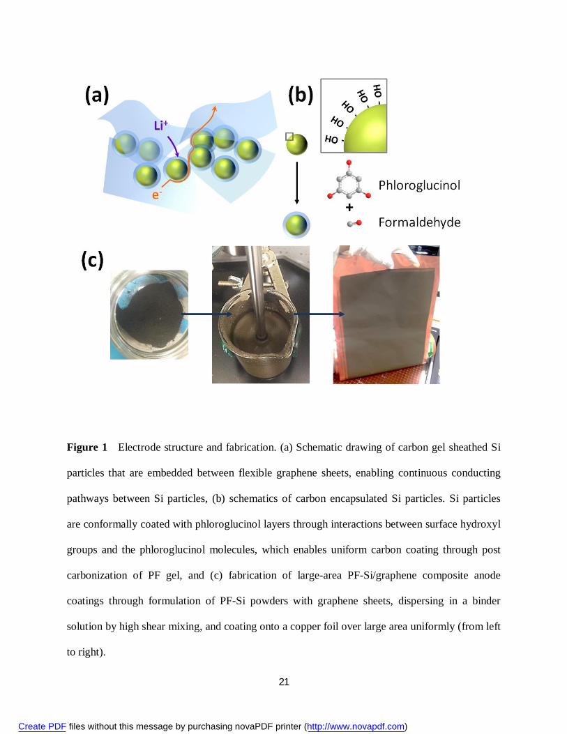
Figure 1 Electrode structure and fabrication. (a) Schematic drawing of carbon gel sheathed Si
particles that are embedded between flexible graphene sheets, enabling continuous conducting
pathways between Si particles, (b) schematics of carbon encapsulated Si particles. Si particles
are conformally coated with phloroglucinol layers through interactions between surface hydroxyl
groups and the phloroglucinol molecules, which enables uniform carbon coating through post
carbonization of PF gel, and (c) fabrication of large-area PF-Si/graphene composite anode
coatings through formulation of PF-Si powders with graphene sheets, dispersing in a binder
solution by high shear mixing, and coating onto a copper foil over large area uniformly (from left
to right).
Create PDF files without this message by purchasing novaPDF printer (http://www.novapdf.com)
22
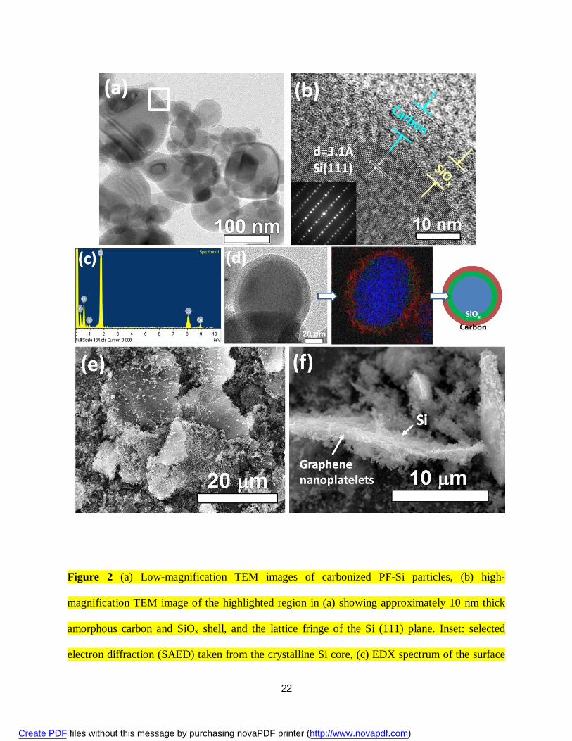
Figure 2 (a) Low-magnification TEM images of carbonized PF-Si particles, (b) high-
magnification TEM image of the highlighted region in (a) showing approximately 10 nm thick
amorphous carbon and SiOx shell, and the lattice fringe of the Si (111) plane. Inset: selected
electron diffraction (SAED) taken from the crystalline Si core, (c) EDX spectrum of the surface
Create PDF files without this message by purchasing novaPDF printer (http://www.novapdf.com)

23
of carbonized PF-Si particles, (d) elemental mapping of Si (blue), oxygen (green) and carbon
(red) further confirming encapsulation of Si, (e) SEM image of PF-Si/graphene composites, and
(f) high-magnification view of PF-Si particles distributed on graphene sheets uniformly.
Create PDF files without this message by purchasing novaPDF printer (http://www.novapdf.com)
24
Figure 3 (a) X-ray diffraction patterns of PF-Si particles carbonized at 800 ºC and graphene
nanoplatelets, and (b) Raman spectra of untreated PF-Si particles, carbonized PF-Si particles and
graphene nanoplatelets.
Create PDF files without this message by purchasing novaPDF printer (http://www.novapdf.com)

25
Figure 4 Electrochemical testing of PF-Si/graphene composite anodes. (a) Galvanostatic
charge/discharge profiles of PF-Si-2/graphene composite anode between 0.02-1.5 V at various
current densities ranging from 0.25 to 2.1 A g-1, (b) specific delithiation capacity and coulombic
efficiency of PF-Si/graphene composite anodes in comparison of pristine Si/graphene anode at a
constant current density of 0.5 A g-1, (c) specific delithiation capacity and coulombic efficiency
Create PDF files without this message by purchasing novaPDF printer (http://www.novapdf.com)
26
of PF-Si/graphene composite anodes at various current densities ranging from 0.25 to 2.1 A g-1,
(d) long-term cycling test of PF-Si-2/graphene composite anode at a constant current density of
0.5 A g-1 and 2.1 A g-1, and (e) Nyquist plots of PF-Si-2/graphene composite anode and pristine
Si/graphene composite anode after 100 charge/discharge cycles at 0.5 A g-1. Both plots displayed
a broad depressed semicircle at high frequencies (>10 Hz) for the charge-transfer kinetic-
controlled region and a straight line at low frequencies for the mass-transfer kinetic-controlled
Warburg region, which can be presented by the equivalent circuit (inset). Rs is equivalent circuit
resistance, Rct is charge-transfer resistance, CPE is constant phase element referring to an electric
double-layer capacitance of non-homogeneous systems, and Ws is Warburg element referring to
an one-dimensional diffusion resistance.
Create PDF files without this message by purchasing novaPDF printer (http://www.novapdf.com)
27
Figure 5 Electrochemical testing of pouch cell prototypes comprising NMC cathode and PF-Si-
2/graphene composite anode. Photograph of a pouch cell lightening a LED (a) under non-
bending, (b) under bending, and (c) a cell before sealing in an Al laminated pouch. (d) 10th and
50th-cycle galvanostatic charge/discharge profiles of the pouch cell at a constant rate of 0.5C
between 3-4.1 V. The 3.8×5.9 cm single electrode pair attained a cell capacity of 26 mAh. (e)
Create PDF files without this message by purchasing novaPDF printer (http://www.novapdf.com)

28
capacity retention and corresponding anode capacity during galvanostatic cycling under non-
bending and bending conditions as shown in (a) and (b). (f) Photograph of a stacked pouch cell
with two pairs of double-sided electrodes and a total cell capacity of 240 mAh, and (g) capacity
retention and corresponding anode capacity during galvanostatic cycling at a constant rate of
0.5C between 3-4.1 V.
Create PDF files without this message by purchasing novaPDF printer (http://www.novapdf.com)
1
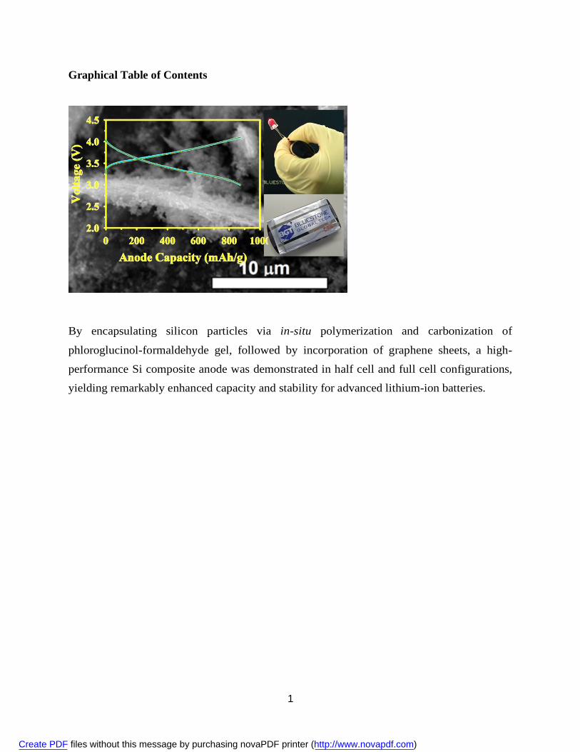
Graphical Table of Contents
By encapsulating silicon particles via in-situ polymerization and carbonization of
phloroglucinol-formaldehyde gel, followed by incorporation of graphene sheets, a high-
performance Si composite anode was demonstrated in half cell and full cell configurations,
yielding remarkably enhanced capacity and stability for advanced lithium-ion batteries.
Create PDF files without this message by purchasing novaPDF printer (http://www.novapdf.com)
2
Composites of Graphene and Encapsulated Silicon for Practically
Viable High-Performance Lithium-Ion Batteries
Xin Zhao*, Minjie Li, Kuo-Hsin Chang, Yu-Ming Lin*
Bluestone Global Tech, 169 Myers Corners Road, Wappingers Falls, NY 12590, USA.
E-mail: [email protected], [email protected]
Abstract
A facile and scalable approach to synthesize silicon composite anode was developed by
encapsulating Si particles via in-situ polymerization and carbonization of phloroglucinol-
formaldehyde gel, followed by incorporation of graphene nanoplatelets. Attributed to the
improved structural integrity, a high packing density and an intimate electrical contact
consolidated by the conductive networks, the composite anode yielded remarkably enhanced
electrochemical performance in terms of charge storage capability, cycling life and coulombic
efficiency. A half cell achieved reversible capacities of 1600 mAh g-1 and 1000 mAh g-1 at 0.5 A
g-1 and 2.1 A g-1, respectively, while retaining more than 70% of the initial capacities over 1000
cycles. Complete lithium-ion pouch cells coupling such anode with lithium metal oxide cathode
demonstrated superior cycling performance and energy output, representing significant advance
in developing Si-based electrode practically applicable to high-performance lithium-ion batteries.
Keywords: Silicon nanoparticles, graphene nanoplatelets, phloroglucinol-formaldehyde gel,
lithium-ion batteries
Create PDF files without this message by purchasing novaPDF printer (http://www.novapdf.com)
3
1 Introduction
The pressing need for advanced battery technologies has accelerated innovation of electrode
formulations to replace conventional intercalation compounds and graphitic materials used in
cathode and anode, respectively, in lithium-ion batteries. Among any known anode materials,
silicon demonstrates the highest gravimetric capacity of 3579 mAh g-1, attributed to the
formation of an alloy composition of Li15Si4 via electrochemical lithiation of Si at room
temperature [1-4]. However, the practical implementation of Si-based anode is notoriously
impeded by its massive volumetric expansion/contraction and subsequent structural pulverization,
as well as the overall swelling in a practical cell format. Besides, electrolyte decomposition at the
freshly formed Si/electrolyte interface along with continual formation of side-reaction products
gradually depletes the available Li ions and isolates the electrode fragments, which severely
hinders the rate capability, deep cycling ability and lifespan of Si-based anode [5-8].
In order to overcome mechanical cracking or fracture during cycling, it is usually necessary to
reduce the particle size of Si, while the potential of nano-sized Si to be fully adopted in
commercial entities is largely sacrificed consequential of reduced tap density and low areal mass
loading [9-11]. Incorporating carbonaceous species into Si offers an alternative solution to
suppress the detrimental effects of volumetric variation and improve the electrical continuity.
However, conformal carbon coatings on Si would rapture readily upon swelling and re-expose it
to side-product deposition [12-14]. Conductive polymers and carbon nanostructures, in particular
carbon nanotubes and their derivatives, provide flexible backbones to better accommodate the Li
ion insertion/extraction stress when introduced into Si anode [15-19]. Nevertheless, the
inherently high surface energy of Si nanoparticles is conducive to electrochemical sintering,
leaving the long-term cycling stability and inferior coulombic efficiency unresolved [20, 21]; the
Create PDF files without this message by purchasing novaPDF printer (http://www.novapdf.com)
4
high surface carbonaceous materials further compromises the coulombic efficiency due to the
formation and propagation of solid electrolyte interphase (SEI), and prevents the high-capacity
anode from being viable when paired with cathodes in full cell formats [9, 22]. As the material
loading increases, the primary Si particles located near the center of large aggregates become
separated from the conductive components, leading to fatal deterioration of overall performance.
Thus until now, there is still a lack of transformative Si anode development and full cell designs
that are compatible with commercial configurations and high-throughput manufacturing
protocols.
Here we report a high-performance Si composite anode constructed from carbon gel sheathed Si
particles and graphene building blocks by a facile and scalable synthetic approach. The Si
particles were encapsulated by a uniform carbonized phloroglucinol- formaldehyde (PF) gel and
enveloped in a graphene platelet matrix (Fig. 1a), which confers a combination of advantageous
features: (1) an intimate electrical contact assured by the carbonaceous networks; (2) a restrained
structural damage and irreversible capacity loss warranted by the SiOx/carbon coating and
graphene sheets in contrast to rigid carbon shells and conventional carbon additives [12, 13, 23];
and (3) a high packing density and sustained structural integrity enabled by the compact graphitic
domains [24, 25]. These synergetic functions afforded superior rate capability, cycling life and
improved volumetric capacity. Proceeded by tape casting and coupling with a formulated lithium
metal oxide cathode, the Si composite anode displayed enhanced performance at practically
viable high mass loading in full cell formats.
2 Experimental
Create PDF files without this message by purchasing novaPDF printer (http://www.novapdf.com)
5
2.1 Synthesis of PF gel encapsulated Si particles
Si powders (~100 nm, Alfa Aesar) were removed from argon environment and exposed to air
overnight. In a typical run, 0.25 g phloroglucinol (Sigma-Aldrich) was dispersed in 5 mL DDI
water under vigorous stirring, followed by dropwise addition of 0.02 g concentrated hydrochloric
acid. 0.73 g Si particles were poured into the suspension, and after stirring at room temperature
for 30 min, 0.26 g 37% formaldehyde aqueous solution (Sigma-Aldrich) was added in. The
mixture was kept at room temperature under stirring until a viscous gel-like structure was
formed. The mixture was vacuum-dried at 70 ºC for overnight, and then calcined at 800 ºC for
2.5 h under a flow of Ar (100 mL min-1).
2.2 Characterization
Sample morphology was investigated using JEOL JSM-7001 scanning electron microscopy and
JEOL JEM-2100F transmission electron microscopy. X-ray diffraction patterns were collected
by a Bruker AXS Gmbh diffractometer with CuK radiation (=1.5418 Å) at 30 kV/10 mA, a
scan rate of 4o min-1. Raman spectra were recorded on a WiTec alpha500 automated confocal
Raman microscope at 532 nm laser excitation. Thermogravimetric analysis was performed by
heating the samples to 800ºC at the rate of 10ºC min-1 in flowing air. The weight loss, after
correcting for oxidation of Si, was used to calculate the carbon fraction. Surface area was
determined from N2 adsorption/desorption isotherm at 77K, collected using Micromeritics ASAP
2000 and analyzed using Brunauer-Emmett-Teller (BET) method.
2.3 Electrochemical measurement
The anode film was fabricated by pasting a slurry containing PF-Si particles, graphene
nanoplatelets (XG Sciences), and poly(acrylic acid) (Sigma-Aldrich) with a weight ratio of 6:3:1
Create PDF files without this message by purchasing novaPDF printer (http://www.novapdf.com)

6
onto a copper foil. The typical mass loading was of the order of 1-4 mg cm-2. The electrode was
dried at 90 ºC under vacuum for overnight, and compressed at 10 MPa before being assembled
into a cell.
Charge/discharge tests versus lithium were carried out using a CR2032-type coin cell. The cells
were assembled in an argon-filled glove box, using a metallic lithium disc as the counter
electrode and a Whatman GF/F microporous borosilicate glass-fiber membrane as the separator.
The electrolyte solution was 1 M LiPF6 in ethylene carbonate/dimethyl carbonate (EC/DMC 1:1
by volume, BASF) plus 10 vol% fluoroethylene carbonate additive. Galvanostatic
charge/discharge measurements were conducted with a Maccor Series 4000 automated test
system at various current densities in the voltage range of 0.02-1.5 V vs. Li/Li+. Electrochemical
impedance spectroscopy (EIS) measurements were conducted using an Ametak VersaSTAT3
potentiostat/galvanostat by applying an AC voltage of 10 mV amplitude and DC open circuit
voltage (OCV) in the frequency range of 1 MHz-0.01 Hz at room temperature. Theoretical
capacity of composite anode is calculated as 3500 mAh g-1 × 60% (Si wt-%) = 2100 mAh g-1
(1C=2.1 A g-1).
For full cell assembly, a lithium nickel cobalt manganese oxide (NMC) cathode was fabricated
by pasting a mixture of LiNi0.5Co0.2Mn0.3O2 powders (Toda America), carbon black (Super C45,
Timcal) and poly(vinylidene fluoride) (Arkema) with a weight ratio of 86:6:8 onto an aluminum
foil. The cathode mass loading was 8.5-20 mg cm-2 and the anode mass loading was 1-3.6 mg
cm-2 on single side. The pair of electrodes was isolated by a Celgard 2325 trilayer separator and
sealed inside an aluminum laminated pouch. The pouch cell was cycled at a constant rate of 0.5C
in the voltage range of 3-4.1 V.
Create PDF files without this message by purchasing novaPDF printer (http://www.novapdf.com)

7
3 Results and discussion
Carbon encapsulated Si particles were fabricated by carbonizing 100 nm-sized Si powders
bonded to phloroglucinol-formaldehyde (PF) gel. The mixture of phloroglucinol and
formaldehyde monomers was selected as an inexpensive carbonaceous precursor, as it undergoes
polymerization under less stringent processing conditions relative to other phenolic resin
monomers [26]. Specifically, Si particles were exposed to air to ensure formation of a stable
hydrophilic oxide layer. The particles were dispersed directly in an aqueous suspension of
phloroglucinol by sonication, and polymerization was completed within three hours at room
temperature, converting the mixture to a gel after addition of formaldehyde in the presence of
hydrochloric acid. The oxide passivation layer was expected to facilitate the dispersing of Si
particles and anchoring of the hydroxyl groups of phloroglucinol to the surface of Si (Fig. 1b) via
a hydrogen-bonding interaction, creating homogeneous tethering to the Si particles and
preventing their sintering into bulk agglomerates.
The PF gel was carbonized in an inert atmosphere at 800 ºC, and tuning of the Si content was
achieved by varying the weight ratio of Si and PF polymer precursors. PF-Si composites with
three different Si contents were prepared, denoted as PF-Si-1, PF-Si-2, and PF-Si-3, with the Si
content of 78%, 83%, and 86%, respectively, as determined by weight losses upon combustion of
the carbon layer in thermogravimetric analysis (Fig. S1 in the ESM). Transmission electron
microscopy (TEM) images confirmed the encapsulation of Si particles with an amorphous and
continuous layer that was ca. 10 nm thick (Fig. 2a and b). The presence of native SiOx was
observed in pristine Si particles [24] and verified by the energy dispersive X-ray (EDX) spectra
Create PDF files without this message by purchasing novaPDF printer (http://www.novapdf.com)
8
taken from the carbonized Si surface (Fig. 2c). An individual Si particle analyzed by elemental
mapping with regard to the distribution of Si, O and C suggested an atomic concentration
gradient across the conformal coating (Fi. 2d). The accumulation of oxygen on the surface of Si
correlated to the native SiOx layer. However, there was no distinct boundary between the carbon
and SiOx coating, probably because of the atom fluxes across the interface during calcination. X-
ray diffraction (XRD) patterns of carbonized Si particles displayed the characteristic peaks of
crystalline Si only, whereas the graphite diffraction peaks were absent (Fig. 3a). Raman
spectroscopy performed at a wavelength of 532 nm depicted a broad peak located at 520 cm-1 in
the carbonized Si particles, which was indicative of crystalline Si and remained unchanged after
calcination (Fig. 3b).
Formulation of PF-Si with graphene was accomplished by mechanical agitation of PF-Si
particles with exfoliated graphene nanoplatelets, in which PF-Si comprised 67% of the total
mass. The graphene nanoplatelets were 5-10 nm thick stacks consisting of graphene sheets, with
an interlayer d-spacing of ca. 3.4 Å (Fig. 3a) and lateral dimension of 10-30 m (Fig. S2 in the
ESM). The graphene nanoplatelets were fabricated by heat exfoliation and mechanical
pulverization, which were employed here in light of a high electrical conductivity and moderate
specific surface area of 120 m2 g-1. The observation of both D (1350 cm-1) and G-band (1610 cm-
1) in the graphene sheets attested to the existence of disordered and ordered carbon features,
respectively. The intensity ratios of the D/G bands corresponded to an approximately 400 nm-
sized ordered graphitic domain fitted to the empirical Tuinstra-Koenig relation [27]. The surface
topology of PF-Si/graphene composites was shown in the scanning electron microscopy (SEM)
images in Fig. 2d. The PF-Si particles were uniformly supported on exfoliated graphene sheets,
leading to a surface area of 41 m2 g-1 for the composite powders. The tap density of the
Create PDF files without this message by purchasing novaPDF printer (http://www.novapdf.com)

9
composite was as high as 1.1 g cm-3, which is very close to that of conventional graphite and
outperforms many other Si/carbon systems, such as recently reported hierarchical (0.49 g cm-3)
[28] or micron-sized (0.78 g cm-3) [10] Si/carbon granules.
The electrochemical performance of pristine Si particles and PF-Si/graphene composites was
evaluated using deep charge/discharge galvanostatic cycling between 1.5-0.02 V (vs. Li/Li+) in a
half-cell setup with Li metal foils as the counter electrode. The first charge/discharge voltage
profile of PF-Si/graphene composites exhibited an extended plateau at ca. 0.1 V, corresponding
to the phase transformation from crystalline Si to lithium silicide (Fig. S3 in the ESM) [29]. A
coulombic efficiency of 70% was obtained for the first cycle. The irreversible capacity loss was
attributed to initial solid electrolyte interphase (SEI) formation, and reactions of Li ions with the
SiOx layer and residual functional groups on the carbon surfaces [30]. The relatively low surface
area of graphene nanoplatelets was beneficial in depressing the SEI growth and thus preserving
electrical contact over cycling, compared to chemical exfoliated and graphene oxide (GO)-
derived graphene [31-34]. It has been suggested that the SiOx reacts with Li ions, forming
irreversible Li4SiO4 or reversible Li2Si2O5 phases, which further assisted the formation of stable
SEI layer [35-37]. Afterwards, the charge/discharge showed sloping profiles characteristic of
lithiation/delithiation of amorphous Si in two different voltage regions (Fig. 4a and S3 in the
ESM). The coulombic efficiency rapidly increased and stabilized at around 99% after 10 cycles,
which was higher than that of previously studied Si/graphene composite anode [24, 38-41].
When cycled at a constant current density of 0.5 A g-1 (0.25C based on the theoretical capacity),
the composite anode PF-Si-2 with 50 wt% Si loading attained the highest reversible capacity of
approximately 1600 mAh g-1 based on the mass of PF-Si particles (Fig. 4b). The rising of
capacity in the beginning few cycles was ascribed to the inward diffusion of electrolyte
Create PDF files without this message by purchasing novaPDF printer (http://www.novapdf.com)

10
throughout the compact network and increasing of accessible surface area of “pushed out” Si
particles [42]. After 300 full charge/discharge cycles, a coulombic efficiency of 99.5% and the
initial capacity was very well retained without any discernible decline. This was equivalent to a
capacity of 1000 mAh g-1 based on the entire laminate weight when taking the mass of graphene
and binder into account. Attributed to a high packing density, the volumetric capacity of the
entire anode reached 1100 mAh cm-3, almost doubling that of conventional graphitic anode (620
mAh cm-3) [43, 44], and is among the best results for engineered Si anode to date [16, 19, 45-
48]. In comparison, the as-received Si nanoparticles supported on graphene exhibited a first
cycle coulombic efficiency of 30% and lost over 50% of the initial value after only 50 cycles,
while all the encapsulated samples showed drastically improved capacity and stability. The
existence of optimum Si loading can be attributed to a combination of balanced factors such as
electrical and ionic conduction throughout the carbonaceous networks, as well as stress
dissipation and structural integrity.
The superior rate capability facilitated by the continuous conducting network and amorphous
carbon coating was evident when charging/discharging the PF-Si/graphene composite anode at
high rates (Fig. 4c). The reversible capacity of PF-Si-2 composite stabilized at 1100 mAh g-1,
maintaining 68% of the original capacity with increasing the rate from 0.25 A g-1 (C/8) to 2.1 A
g-1 (1C). When switching back to the initial rate, the original capacity was fully recovered. At a
constant rate of 2.1 A g-1, a single charge/discharge cycle took only 15 minutes, while the
capacity fade was as low as < 0.04% per cycle up to 1000 cycles on average (Fig. 4d). The
volumetric capacity remained a quite high value of 730 mAh g-1 after 500 cycles. Despite higher
gravimetric capacities > 2000 mAh g-1 given by various Si nanostructures e.g. Si nanowires [5,
18, 49], nanotubes [13] and hollow spheres or monolithics [7, 14], our composite anode achieved
Create PDF files without this message by purchasing novaPDF printer (http://www.novapdf.com)

11
an unprecedented balance across capacity and retention at high rates and long-term cycling,
which is more competitive than previously reported nanostructured Si-based anode [16-20, 37-
41, 45-48, 50]. Notably, even at a high mass loading of 4 mg cm-2, there was almost no
degradation in the capacity (Fig. S5 in the ESM). Electrochemical impedance spectroscopy (EIS)
further confirmed the improved charge-transfer and Li ion diffusion kinetics of PF-Si particles
compared to pristine Si (Fig. 4e). Both the Ohmic resistance Rs (real impedance at 100 kHz, ~3
) and the charge-transfer resistance Rct (estimated diameter of the semicircle, ~65 ) of the PF-
Si-2/graphene anode were smaller that of the pristine Si/graphene anode (Rs~14 Rct~125
when fitted to the equivalent circuit in the inset of Fig. 4e [51], accompanied with a less
inclined Warburg region for the PF-Si-2/graphene anode contrasting the pristine Si/graphene
anode.
To validate the anode performance in a full cell, the PF-Si-2/graphene anode was coupled with a
NMC cathode and sealed in a laminated pouch with tab leads extending out (Fig. 5). The NMC
was selected via a cathode screening, because of its satisfactory capacity and lifetime, a relative
flat voltage plateau and reasonably high operating potential (Fig. S4 in the ESM). The
insufficient initial coulombic efficiency of the anode film can be tackled by prelithiation prior to
incorporation into the pouch cell battery [52]. The balancing mass ratio of anode (1.2 mg cm-2)
and cathode materials (8.5 mg cm-2) was set as 1:7 by using the total capacity of 1000 mAh g-1
and 140 mAh g-1 for anode and cathode, respectively. When cycled between 3 and 4.1 V at a
constant rate of 0.5C, the cell reversibly charged and discharged with stable capacity retention
close to its designed cell capacity of 1.2 mAh cm-2, showing a potential plateau at around 3.5 V
(Fig. 5d). After 100 cycles, the cell maintained 85% of its initial capacity (Fig. 5e), while
delivering a high gravimetric energy density of 420 Wh kg-1 based upon the total mass of
Create PDF files without this message by purchasing novaPDF printer (http://www.novapdf.com)
12
electrode materials. The corresponding anode capacity was ca. 930 mAh g-1 at maximum, closed
to 90% depth-of-discharge (DOD). The pouch cell with a single pair of electrodes was flexible
and could suffer medium strain without malfunction. The variation in the discharge
characteristics and cycling stability was quite negligible between the bending and non-bending
states. The anode coating remained integral after cycling (Fig. S6 in the ESM), while the
capacity retention of pouch cells after 50 cycles could be hurdled by gas evolution and cell
swelling resulted from electrolyte decomposition and side reactions induced by residual
moisture.
By applying slightly excess anode materials, a stacked pouch cell consisting of two pairs of
double-sided cathode/anode couple was fabricated, with a designed anode capacity of the order
of 800 mAh g-1 (3.6 mg cm-2 one side). The cell exhibited a total capacity of 240 mAh with only
4% of capacity decay after 60 cycles, while the areal capacity of a single pair of electrode
attained 5.6 mAh cm-2, which already exceeds that offered by commercial Li-ion batteries for
smart phones and tablets. Further extension of cycling life can be envisaged by designing stable
SEI layers, optimizing the cut-off voltage window and switching to moisture controlled or
automatic cell production environment.
4 Conclusions
In conclusion, carbon encapsulation of Si particles enabled by in-situ polymerization and
carbonization of phloroglucinol-formaldehyde gel was successfully demonstrated as an effective
and high-throughput strategy for high-performance Si anode. Enveloping the carbon/SiOx
sheathed Si particles in graphene sheets further eliminated pulverization and electrical isolation
Create PDF files without this message by purchasing novaPDF printer (http://www.novapdf.com)

13
of active materials, resulting in a composite with excellent gravimetric and volumetric capacity,
rate capability and cyclability. Very significantly, the preparation method employed can be easily
adapted and scaled up to existing high-throughput protocols for electrode and cell manufacture.
As-assembled pouch cell batteries incorporating the composite anode rendered stable energy
outputs and storage capabilities when subjected to long cycling, allowing a promising boost for
the realization of high-performance energy storage devices.
Acknowledgements
The authors acknowledge Dr. Thanasis Georgiou for his assistance on TGA measurement.
Electronic Supplementary Material: Supplementary material is available in the online version of
this article at:
References
[1] Boukamp, B. A.; Lesh, G. C.; Huggins, R. A. All-solid lithium electrodes with mixed-
conductor matrix. J. Electrochem. Soc. 1981, 128, 725-729.
[2] Larcher, D.; Beattie, S.; Morcrette, M.; Edström, K.; Jumas, J.-C.; Tarascon, J.-M. Recent
finds and prospects in the field of pure metals as negative electrodes for Li-ion batteries. J.
Mater. Chem. 2007, 17, 3759-3772.
[3] Obrovac, M. N.; Christensen, L. Structural changes in silicon anodes during lithium
insertion/extraction. Electrochem. Solid-State Lett. 2004, 7, A93–A96.
Create PDF files without this message by purchasing novaPDF printer (http://www.novapdf.com)
14
[4] Key, B.; Bhattacharyya, R.; Morcrette, M.; Seznéc, V.; Tarascon, J.-M.; Grey, C. P. Real-
time NMR investigations of structural changes in silicon electrodes for lithium-ion batteries. J.
Am. Chem. Soc. 2009, 131, 9239-9249.
[5] Chan, C. K.; Peng, H.; Liu, G.; McIlwrath, K.; Zhang, X. F.; Huggins, R. A.; Cui, Y. High-
performance lithium battery anodes using silicon nanowires. Nat. Nanotech. 2008, 3, 31-35.
[6] Oumellal, Y.; Delpuech, N.; Mazouzi, D.; Dupré, N.; Gaubicher, J.; Moreau, P.; Soudan, P.;
Lestriez, B.; Guyomard, D. The failure mechanism of nano-sized Si-based negative electrodes
for lithium ion batteries. J. Mater. Chem. 2011, 21, 6201-6208.
[7] Kim, H.; Han, B.; Choo, J.; Cho, J. Three-dimensional porous silicon particles for use in
high-performance lithium secondary batteries. Angew. Chem. Int. Ed. 2008, 47, 10151-10154.
[8] Kim, H.; Seo, M.; Park, M.-H.; Cho, J. A critical size of silicon nano-anodes for lithium
rechargeable batteries. Angew. Chem. Int. Ed. 2010, 49, 2146-2149.
[9] Bruce, P. G.; Scrosati, B.; Tarascon, J.-M. Nanomaterials for rechargeable lithium batteries.
Angew. Chem. Int. Ed. 2008, 47, 2930-2946.
[10] Yi, R.; Dai, F.; Gordin, M. L.; Chen, S.; Wang, D. Micro-sized Si-C composite with
interconnected nanoscale building blocks as high-performance anodes for practical application
in lithium-ion batteries. Adv. Energy Mater. 2013, 3, 295-300.
[11] Jeong, G.; Kim, Y.-U.; Kim, H.; Kim, Y.-J.; Sohn, H.-J. Prospective materials and
applications for Li secondary batteries. Energy Environ. Sci. 2011, 4, 1986-2002.
Create PDF files without this message by purchasing novaPDF printer (http://www.novapdf.com)

15
[12] Luo, J.; Zhao, X.; Wu, J.; Jang, H. D.; Kung, H. H.; Huang, J. Crumpled graphene-
encapsulated Si nanoparticles for lithium ion battery anodes. J. Phys. Chem. Lett. 2012, 3,
1824-1829.
[13] Wu, H.; Chan, G.; Choi, J. W.; Ryu, I.; Yao, Y.; McDowell, M. T.; Lee, S. W.; Jackson, A.;
Yang, Y.; Hu, L.; Cui, Y. Stable cycling of double-walled silicon nanotube battery anodes
through solid-electrolyte interphase control. Nat. Nanotech. 2012, 7, 310-315.
[14] Wu, H.; Zheng, G.; Liu, N.; Carney, T. J.; Yang, Y.; Cui, Y. Engineering empty space
between Si nanoparticles for lithium-ion battery anodes. Nano Lett. 2012, 12, 904-909.
[15] Liu, G.; Xun, S.; Vukmirovic, N.; Song, X.; Olalde-Velasco, P.; Zheng, H.; Battaglia, V. S.;
Wang, L.; Yang, W. Polymers with tailored electronic structure for high-capacity lithium
battery electrodes. Adv. Mater. 2011, 23, 4579-4683.
[16] Wu, M.; Xiao, X.; Vukmirovic, N.; Xun, S.; Das, P. K.; Song, X.; Olalde-Velasco, P.;
Wang, D.; Weber, A. Z.; Wang, L.-W.; Battaglia, V. S.; Yang, W.; Liu, G. Toward an ideal
polymer binder design for high-capacity battery anodes. J. Am. Chem. Soc. 2013, 135, 12048-
12056.
[17] Evanoff, K.; Benson, J.; Schauer, M.; Kovalenko, I.; Lashmore, D.; Ready, W. J.; Yushin,
G. Ultra strong silicon-coated carbon nanotube nonwoven fabric as a multifunctional lithium-
ion battery anode. ACS Nano 2012, 6, 9837-9845.
[18] Liu, B.; Wang, X.; Chen, H.; Wang, Z.; Chen, D.; Cheng, Y.-B.; Zhou, C.; Shen, G.
Hierarchical silicon nanowires-carbon textiles matrix as a binder-free anode for high-
performance advanced lithium-ion batteries. Scientific Reports 2013, 3, 1622-1628.
Create PDF files without this message by purchasing novaPDF printer (http://www.novapdf.com)
16
[19] Wu, H.; Yu, G.; Pan, L.; Liu, N.; McDowell, M. T.; Bao, Z.; Cui, Y. Stable Li-ion battery
anodes by in-situ polymerization of conducting hydrogel to conformally coat silicon
nanoparticles. Nat. Commun. 2013, 4, 1943-1948.
[20] Ji, L.; Zheng, H.; Ismach, A.; Tan, Z.; Xun, S.; Lin, E.; Battaglia, V.; Srinivasan, V.; Zhang,
Y. Graphene/Si multilayer structure anodes for advanced high and full lithium-ion cells. Nano
Energy 2012, 1, 164-171.
[21] Piper, D. M.; Yersak, T. A.; Son, S.-B.; Kim, S. C.; Kang, C. S.; Oh, K. H.; Ban, C.; Dillon,
A. C.; Lee, S.-H. Conformal coatings of cyclized-PAN for mechanically resilient Si nano-
composite anodes. Adv. Energy Mater. 2013, 3, 697-702.
[22] Forney, M. W.; Ganter, M. J.; Staub, J. W.; Ridgley, R. D.; Landi, B. J. Prelithiation of
silicon-carbon nanotube anodes for lithium ion batteries by stabilizing lithium metal powders
(SLMP). Nano Lett. 2013, 13, 4158-4163.
[23] Wang, K.; He, X.; Wang, L.; Ren, J.; Liang, C.; Wan, C. Si, Si/Cu core in carbon shell
composite as anode material in lithium-ion batteries. Solid State Ionics 2007, 178, 115-118.
[24] Zhao, X.; Hayner, C. M.; Kung, M. C.; Kung, H. H. In-plane vacancy-enabled highi-power
Si-graphene composite electrode for lithium-ion batteries. Adv. Energy Mater. 2011, 1, 1079-
1084.
[25] Evanoff, K.; Magasinski, A.; Yang, J.; Yushin, G. Nanosilicon-coated graphene granules as
anode for Li-ion batteries. Adv. Energy Mater. 2011, 1, 495-498.
[26] Liang, C.; Dai, S. Synthesis of mesoporous carbon materials via enhanced hydrogen-
bonding interaction. J. Am. Chem. Soc. 2006, 128, 5316-5317.
Create PDF files without this message by purchasing novaPDF printer (http://www.novapdf.com)
17
[27] Tuinstra, F.; Koenig, J. L. Raman spectrum of graphite. J. Chem. Phys. 1970, 53, 1126-
1130.
[28] Magasinski, A.; Dixon, P.; Hertzberg, B.; Kvit, A.; Ayala, J.; Yushin, G. High-performance
lithium-ion anodes using a hierarchical bottom-up approach. Nat. Mater. 2010, 9, 353-358.
[29] McDowell, M. T.; Lee, S. W.; Nix, W. D.; Cui, Y. Understanding the lithiation of silicon
and other alloying anodes for lithium-ion batteries. Adv. Mater. 2013, 25, 4966-4985.
[30] Pistoia, G. Lithium Batteries: New Materials, Developments and Perspectives, Elsevier
Science, Amsterdam 1994.
[31] Li, D.; Müller, M. B.; Gilje, S.; Kaner, R. B.; Wallace, G. G. Processable aqueous
dispersions of graphene nanosheets. Nat. Nanotech. 2008, 3, 101-105.
[32] Jeon, I.-Y.; Choi, H.-J.; Choi, M.; Seo, J.-M.; Jung, S.-M.; Kim, M.-J.; Zhang, S.; Zhang,
L.; Xia, Z.; Dai, L.; Park, N.; Baek, J.-B. Facile, scalable synthesis of edge-halogenated
graphene nanoplatelets as efficient metal-free electrocatalysts for oxygen reduction reaction.
Scientific Reports 2013, 3, 1810-1816.
[33] Park, S.; Ruoff, R. S. Chemical methods for the production of graphenes. Nat. Nanotech.
2009, 4, 217-224.
[34] Dreyer, D. R.; Park, S.; Bielawski, C. W.; Ruoff, R. S. The chemistry of graphene oxide.
Chem. Soc. Rev. 2010, 39, 228-240.
[35] Chang, W.-S.; Park, C.-M.; Kim, J.-H.; Kim, Y.-U.; Jeong, G.; Sohn, H.-J. Quartz (SiO2): a
new energy storage anode material for Li-ion batteries. Energy & Environ. Sci. 2012, 5, 6895-
6899.
Create PDF files without this message by purchasing novaPDF printer (http://www.novapdf.com)

18
[36] Song, S.-W.; Baek, S.-W. Silane-Derived SEI stabilization on thin-film electrodes of
nanocrystalline Si for lithium batteries. Electrochem. Solid-State Lett. 2009, 12, A23-27.
[37] Hassan, F. M.; Chabot, V.; Elsayed, A. R.; Xiao, X.; Chen, Z. Engineered Si electrode
nanoarchitecture: a scalable postfabrication treatment for the production of next-generation Li-
ion batteries. Nano Lett. in press, DOI: 10.1021/nl403943g.
[38] Lee, J. K.; Smith, K. B.; Hayner, C. M.; Kung, H. H. Silicon nanoparticles-graphene paper
composites for Li ion battery anodes. Chem. Commun. 2010, 46, 2025-2027.
[39] Zhou, X.; Yin, Y.-X.; Wan, L.-J.; Guo, Y.-G. Self-assembled nanocomposite of silicon
nanoparticles encapsulated in graphene through electrostatic attraction for lithium-ion batteries.
Adv. Energy Mater. 2012, 2, 1086-1090.
[40] Wang, B.; Li, X.; Zhang, X.; Luo, B.; Jin, M.; Liang, M.; Dayeh, S. A.; Picraux, S. T.; Zhi,
L. Adaptable silicon-carbon nanocables sandwiched between reduced graphene oxide sheets as
lithium ion battery anodes. ACS Nano 2013, 7, 1437-1445.
[41] Zhou, M.; Pu, F.; Wang, Z.; Cai, T.; Chen, H.; Zhang, H.; Guan, S. Facile synthesis of novel
Si nanoparticles-graphene composites as high-performance anode materials for Li-ion
batteries. Phys. Chem. Chem. Phys. 2013, 15, 11394-11401.
[42] Liu, X. H.; Zhong, L.; Huang, S.; Mao, S. X.; Zhu, T.; Huang, J. Y. Size-dependent fracture
of silicon nanoparticles during lithiation. ACS Nano 2012, 6, 1522-1531.
[43] Dahn, J. R.; Seel, J. A. Energy and capacity projections for practical dual-graphite cells. J.
Electrochem. Soc. 2000, 147, 899-901.
Create PDF files without this message by purchasing novaPDF printer (http://www.novapdf.com)

19
[44] Zhang, S. S.; Jow, T. R. Study of poly(acrylonitrile-methyl methacrylate) as binder for
graphite anode and LiMn2O4 cathode of Li-ion batteries. J. Power Sources 2002, 109, 422-426.
[45] Wang, B.; Li, X.; Qiu, T.; Luo, B.; Ning, J.; Li, J.; Zhang, X.; Liang, M.; Zhi, L. High
volumetric capacity silicon-based lithium battery anodes by nanoscale system engineering.
Nano Lett. 2013, 13, 5578-5584.
[46] Kovalenko, I.; Zdyrko, B.; Magasinski, A.; Hertzberg, B.; Milicev, Z.; Burtovyy, R.;
Luzinov, I.; Yushin, G. A major constituent of brown algae for use in high-capacity Li-ion
batteries. Science, 2011, 334, 75-79.
[47] Lee, J.-I.; Choi, N.-S.; Park, S. Highly stable Si-based multicomponent anodes for practical
use in lithium-ion batteries. Energy & Environ. Sci. 2012, 5, 7878-7882.
[48] Gauthier, M.; Mazouzi, D.; Reyter, D.; Lestriez, B.; Moreau, P.; Guyomard, D.; Roué, L. A
low-cost and high performance ball milled Si-based negative electrode for high energy Li-ion
batteries. Energy & Environ. Sci. 2013, 6, 2145-2155.
[49] Ge, M.; Rong, J.; Fang, X.; Zhou, C. Porous doped silicon nanowires for lithium ion battery
anode with long cycle life. Nano Lett. 2012, 12, 2318-2323.
[50] Deng, J.; Ji, H.; Yan, C.; Zhang, J.; Si, W.; Baunack, S.; Oswald, S.; Mei, Y.; Schmidt, O.
G. Naturally rolled-up C/Si/C trilayer nanomembranes as stable anodes for lithium-ion
batteries with remarkable cycling performance. Angew. Chem. Int. Ed. 2013, 52, 2326-2330.
[51] Barsoukov, E.; Macdonald, J. R. Impedance Spectroscopy: Theory, Experiment, and
Applications, John Wiley&Sons, 2005.
Create PDF files without this message by purchasing novaPDF printer (http://www.novapdf.com)

20
[52] Hassoun, J.; Lee, K.-S.; Sun, Y.-K.; Scrosati, B. An advanced lithium ion battery based on
high performance electrode materials. J. Am. Chem. Soc. 2011, 133, 3139-3143.
Create PDF files without this message by purchasing novaPDF printer (http://www.novapdf.com)

21
Figure 1 Electrode structure and fabrication. (a) Schematic drawing of carbon gel sheathed Si
particles that are embedded between flexible graphene sheets, enabling continuous conducting
pathways between Si particles, (b) schematics of carbon encapsulated Si particles. Si particles
are conformally coated with phloroglucinol layers through interactions between surface hydroxyl
groups and the phloroglucinol molecules, which enables uniform carbon coating through post
carbonization of PF gel, and (c) fabrication of large-area PF-Si/graphene composite anode
coatings through formulation of PF-Si powders with graphene sheets, dispersing in a binder
solution by high shear mixing, and coating onto a copper foil over large area uniformly (from left
to right).
Create PDF files without this message by purchasing novaPDF printer (http://www.novapdf.com)

22
Figure 2 (a) Low-magnification TEM images of carbonized PF-Si particles, (b) high-
magnification TEM image of the highlighted region in (a) showing approximately 10 nm thick
amorphous carbon and SiOx shell, and the lattice fringe of the Si (111) plane. Inset: selected
electron diffraction (SAED) taken from the crystalline Si core, (c) EDX spectrum of the surface
Create PDF files without this message by purchasing novaPDF printer (http://www.novapdf.com)

23
of carbonized PF-Si particles, (d) elemental mapping of Si (blue), oxygen (green) and carbon
(red) further confirming encapsulation of Si, (e) SEM image of PF-Si/graphene composites, and
(f) high-magnification view of PF-Si particles distributed on graphene sheets uniformly.
Create PDF files without this message by purchasing novaPDF printer (http://www.novapdf.com)

24
Figure 3 (a) X-ray diffraction patterns of PF-Si particles carbonized at 800 ºC and graphene
nanoplatelets, and (b) Raman spectra of untreated PF-Si particles, carbonized PF-Si particles and
graphene nanoplatelets.
Create PDF files without this message by purchasing novaPDF printer (http://www.novapdf.com)
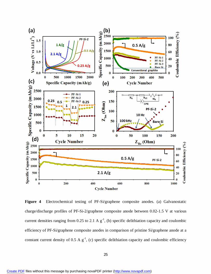
25
Figure 4 Electrochemical testing of PF-Si/graphene composite anodes. (a) Galvanostatic
charge/discharge profiles of PF-Si-2/graphene composite anode between 0.02-1.5 V at various
current densities ranging from 0.25 to 2.1 A g-1, (b) specific delithiation capacity and coulombic
efficiency of PF-Si/graphene composite anodes in comparison of pristine Si/graphene anode at a
constant current density of 0.5 A g-1, (c) specific delithiation capacity and coulombic efficiency
Create PDF files without this message by purchasing novaPDF printer (http://www.novapdf.com)

26
of PF-Si/graphene composite anodes at various current densities ranging from 0.25 to 2.1 A g-1,
(d) long-term cycling test of PF-Si-2/graphene composite anode at a constant current density of
0.5 A g-1 and 2.1 A g-1, and (e) Nyquist plots of PF-Si-2/graphene composite anode and pristine
Si/graphene composite anode after 100 charge/discharge cycles at 0.5 A g-1. Both plots displayed
a broad depressed semicircle at high frequencies (>10 Hz) for the charge-transfer kinetic-
controlled region and a straight line at low frequencies for the mass-transfer kinetic-controlled
Warburg region, which can be presented by the equivalent circuit (inset). Rs is equivalent circuit
resistance, Rct is charge-transfer resistance, CPE is constant phase element referring to an electric
double-layer capacitance of non-homogeneous systems, and Ws is Warburg element referring to
an one-dimensional diffusion resistance.
Create PDF files without this message by purchasing novaPDF printer (http://www.novapdf.com)

27
Figure 5 Electrochemical testing of pouch cell prototypes comprising NMC cathode and PF-Si-
2/graphene composite anode. Photograph of a pouch cell lightening a LED (a) under non-
bending, (b) under bending, and (c) a cell before sealing in an Al laminated pouch. (d) 10th and
50th-cycle galvanostatic charge/discharge profiles of the pouch cell at a constant rate of 0.5C
between 3-4.1 V. The 3.8×5.9 cm single electrode pair attained a cell capacity of 26 mAh. (e)
Create PDF files without this message by purchasing novaPDF printer (http://www.novapdf.com)

28
capacity retention and corresponding anode capacity during galvanostatic cycling under non-
bending and bending conditions as shown in (a) and (b). (f) Photograph of a stacked pouch cell
with two pairs of double-sided electrodes and a total cell capacity of 240 mAh, and (g) capacity
retention and corresponding anode capacity during galvanostatic cycling at a constant rate of
0.5C between 3-4.1 V.
Create PDF files without this message by purchasing novaPDF printer (http://www.novapdf.com)
Top Related