


Languages
Pages
Legal


2008 Chapter-3 L05: "Embedded Systems - " , Raj Kamal, Publs.: McGraw-Hill Education 1
DEVICES AND COMMUNICATIONBUSES FOR DEVICES NETWORK––
LessonLesson--5: 5: SPI, SCI, SI and SDIO SPI, SCI, SI and SDIO Port/devices for Serial Data Port/devices for Serial Data Communication Communication
2008 Chapter-3 L05: "Embedded Systems - " , Raj Kamal, Publs.: McGraw-Hill Education 2
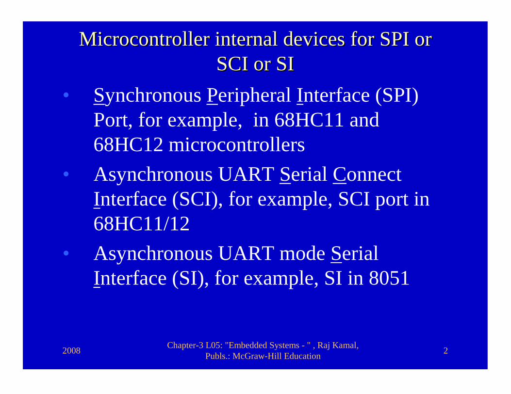
Microcontroller internal devices for SPI or Microcontroller internal devices for SPI or SCI or SISCI or SI
• Synchronous Peripheral Interface (SPI) Port, for example, in 68HC11 and 68HC12 microcontrollers
• Asynchronous UART Serial Connect Interface (SCI), for example, SCI port in 68HC11/12
• Asynchronous UART mode Serial Interface (SI), for example, SI in 8051
2008 Chapter-3 L05: "Embedded Systems - " , Raj Kamal, Publs.: McGraw-Hill Education 3
1. SPI1. SPI

2008 Chapter-3 L05: "Embedded Systems - " , Raj Kamal, Publs.: McGraw-Hill Education 4
SPISPI
� Full-duplex Synchronous communication. � SCLK, MOSI and MISO signals for serial
clock from master, output from master and input to master, respectively.
� Device selection as master or slave can be done by a signal to hardware input SS. (Slave select when 0) pin

2008 Chapter-3 L05: "Embedded Systems - " , Raj Kamal, Publs.: McGraw-Hill Education 5
SPI signalsSPI signals
SS
MOSIMISOSCLK
Slave Select input (for defining an SPI device as slave when SS active, else it is master)
At master input at slave output
Clock output at master and input at slave
At Master output and at slave input
SS
MOSIMISOSCLK
SS
MOSIMISOSCLK
1 0Master SPI Slave SPI
2008 Chapter-3 L05: "Embedded Systems - " , Raj Kamal, Publs.: McGraw-Hill Education 6
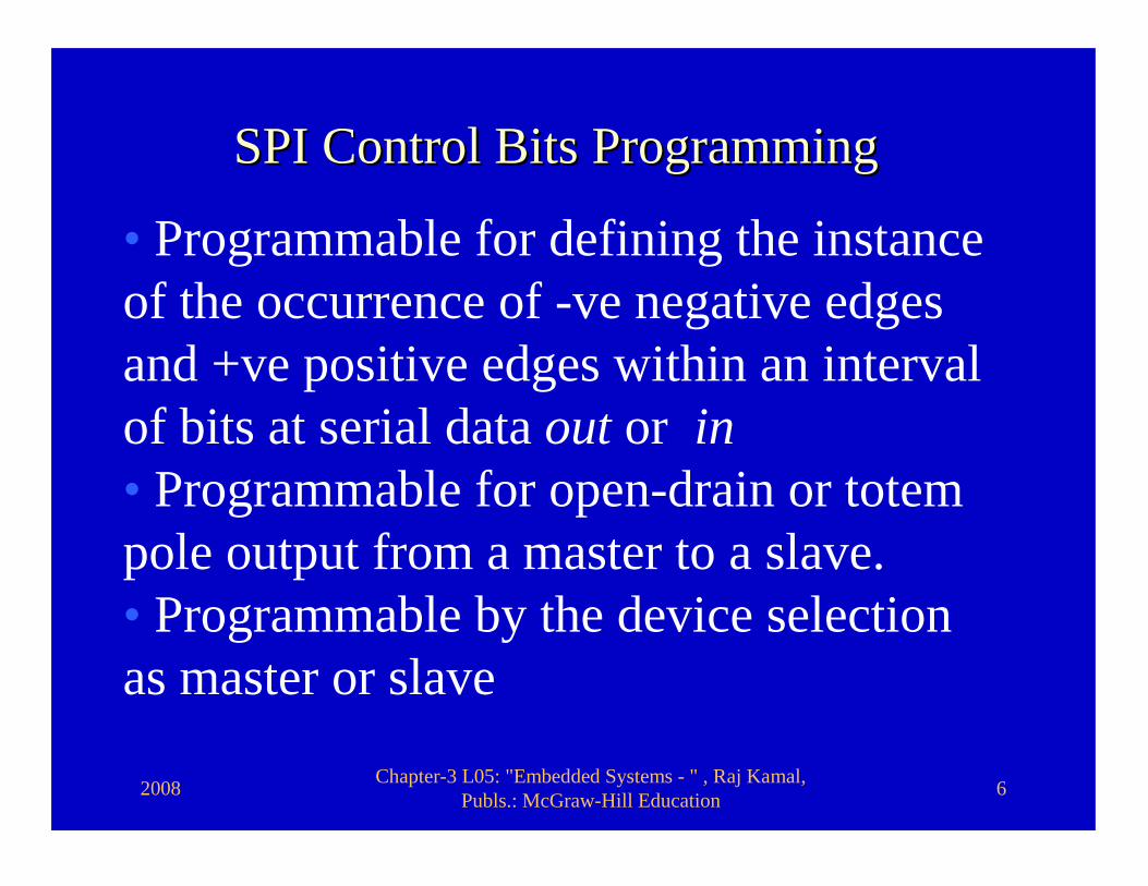
SPI Control Bits ProgrammingSPI Control Bits Programming
• Programmable for defining the instance of the occurrence of -ve negative edges and +ve positive edges within an interval of bits at serial data out or in• Programmable for open-drain or totem pole output from a master to a slave.• Programmable by the device selection as master or slave

2008 Chapter-3 L05: "Embedded Systems - " , Raj Kamal, Publs.: McGraw-Hill Education 7
• Programmable for the clock bits, and therefore of the period T of serial out data bits− down to the interval of 0.5µs for an 8 MHz crystal at 68HC11
SPI Control Bits SPI Control Bits ProgrammingProgramming

2008 Chapter-3 L05: "Embedded Systems - " , Raj Kamal, Publs.: McGraw-Hill Education 8
68HC11/12 synchronous serial 68HC11/12 synchronous serial communicationcommunication
� SPI (Serial Peripheral Interface)
2008 Chapter-3 L05: "Embedded Systems - " , Raj Kamal, Publs.: McGraw-Hill Education 9
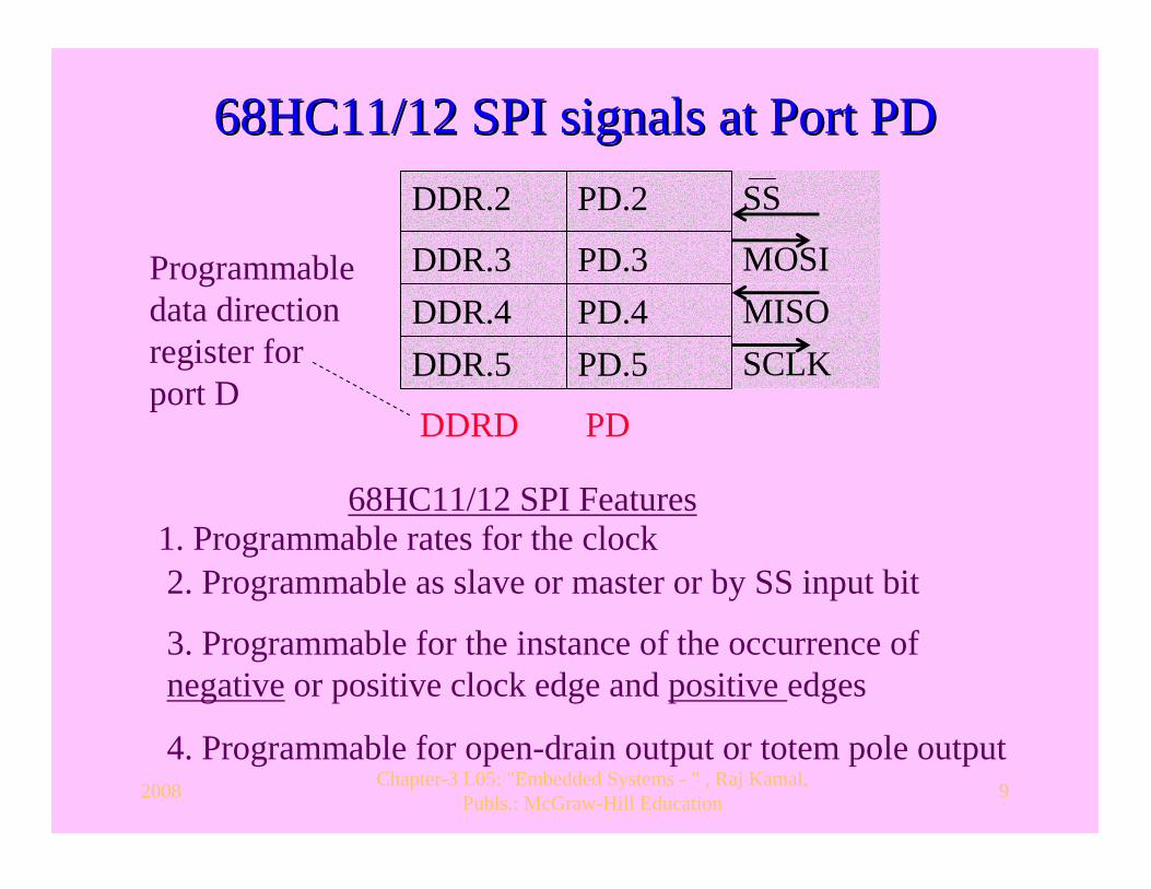
68HC11/12 SPI signals at Port PD68HC11/12 SPI signals at Port PDSS
MOSIMISOSCLK
1. Programmable rates for the clock
3. Programmable for the instance of the occurrence of negative or positive clock edge and positive edges
4. Programmable for open-drain output or totem pole output
2. Programmable as slave or master or by SS input bit
DDR.2
DDR.3DDR.4DDR.5
DDRD
PD.2
PD.3PD.4PD.5
PD
Programmabledata direction register for port D
68HC11/12 SPI Features
2008 Chapter-3 L05: "Embedded Systems - " , Raj Kamal, Publs.: McGraw-Hill Education 10
2. SCI2. SCI
2008 Chapter-3 L05: "Embedded Systems - " , Raj Kamal, Publs.: McGraw-Hill Education 11
Serial Connect Interface (SCI) PortSerial Connect Interface (SCI) Port
� UART asynchronous mode port� Full-duplex mode� SCI programmable for transmission
and for reception

2008 Chapter-3 L05: "Embedded Systems - " , Raj Kamal, Publs.: McGraw-Hill Education 12
SCI Full duplex signalsSCI Full duplex signals
RxDTxD At transmitter output for a receiver
input
At receiver input from a transmitter output
RxD
TxD
TxD
RxD
UART Transceiver Transceiver
UART
Transceiver
2008 Chapter-3 L05: "Embedded Systems - " , Raj Kamal, Publs.: McGraw-Hill Education 13
SCI Control bits ProgrammingSCI Control bits Programming� Programmability for SCI baud rates are
fixed as per rate and prescaling bits � Serial in and out lines baud rate not
separately programmable� Baud rate is selectable among 32 possible
ones by the three- rate bits and two prescaling bits.
� SCI two control register bits, T8 and R8 for the inter-processor communication in 11-bit format.
2008 Chapter-3 L05: "Embedded Systems - " , Raj Kamal, Publs.: McGraw-Hill Education 14
SCI Control bits ProgrammingSCI Control bits Programming� SCI receiver wake up feature programmable
by RWU (Receiver wakeup Unavailable bit) � Feature enabled if RWU (1st bit of SCC2,
Serial Communication Control Register 2) is set, and is disabled if RWU is reset.
� If RWU if set, then the receiver of a slave does not interrupt by the succeeding frames.
� Number of processors can communicate on the SCI bus using control bits RWU, R8 and T8

2008 Chapter-3 L05: "Embedded Systems - " , Raj Kamal, Publs.: McGraw-Hill Education 15
68HC11/12 asynchronous serial 68HC11/12 asynchronous serial communicationcommunication
� One SCI and standard baud rates can be set up to 9.6 kbps only in 68HC11
� 68HC12 provides two SCIs that can operate at two different clock rates.
� 68HC12 baud rates can be set up to 38.4 kbps.
2008 Chapter-3 L05: "Embedded Systems - " , Raj Kamal, Publs.: McGraw-Hill Education 16
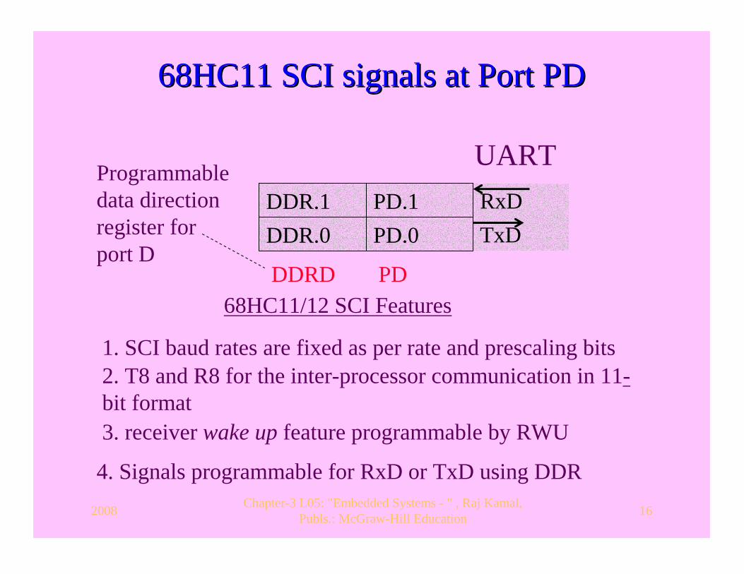
68HC11 SCI signals at Port PD68HC11 SCI signals at Port PD
RxDTxD
1. SCI baud rates are fixed as per rate and prescaling bits
3. receiver wake up feature programmable by RWU
4. Signals programmable for RxD or TxD using DDR
2. T8 and R8 for the inter-processor communication in 11-bit format
DDR.1DDR.0
DDRD
PD.1PD.0
PD
Programmabledata direction register for port D
68HC11/12 SCI Features
UART
2008 Chapter-3 L05: "Embedded Systems - " , Raj Kamal, Publs.: McGraw-Hill Education 17
3. SI3. SI
2008 Chapter-3 L05: "Embedded Systems - " , Raj Kamal, Publs.: McGraw-Hill Education 18
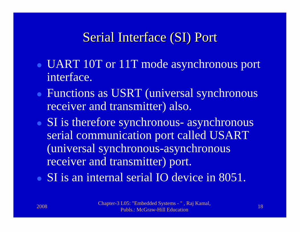
Serial Interface (SI) PortSerial Interface (SI) Port
� UART 10T or 11T mode asynchronous port interface.
� Functions as USRT (universal synchronous receiver and transmitter) also.
� SI is therefore synchronous- asynchronous serial communication port called USART (universal synchronous-asynchronous receiver and transmitter) port.
� SI is an internal serial IO device in 8051.
2008 Chapter-3 L05: "Embedded Systems - " , Raj Kamal, Publs.: McGraw-Hill Education 19
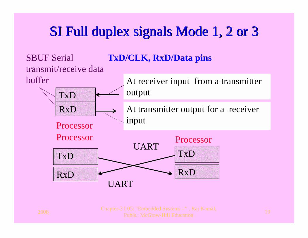
SI Full duplex signals Mode 1, 2 or 3SI Full duplex signals Mode 1, 2 or 3
TxDRxD At transmitter output for a receiver
input
At receiver input from a transmitter output
TxD
RxD
TxD
RxD
UART Processor Processor
UART
Processor
TxD/CLK, RxD/Data pinsSBUF Serial transmit/receive data buffer
2008 Chapter-3 L05: "Embedded Systems - " , Raj Kamal, Publs.: McGraw-Hill Education 20
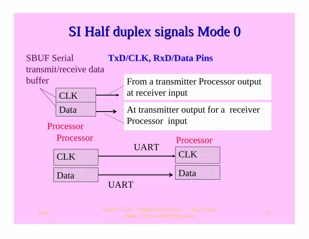
SI Half duplex signals Mode 0SI Half duplex signals Mode 0
CLKData At transmitter output for a receiver
Processor input
From a transmitter Processor outputat receiver input
CLK
Data
CLK
Data
UART Processor Processor
UART
Processor
TxD/CLK, RxD/Data PinsSBUF Serial transmit/receive data buffer

2008 Chapter-3 L05: "Embedded Systems - " , Raj Kamal, Publs.: McGraw-Hill Education 21
SI Control bits programming SI Control bits programming � Mode 0− Half- duplex synchronous
mode of operation, called. When a 12 MHz crystal is at 8051, and is attached to the processor, the clock bits are at the intervals of 1 µs.
� Mode 1 or 2 or 3− Full- duplex asynchronous serial communication.
� Modes 1 and 3 baud rate programmed−Using the timer bits.
2008 Chapter-3 L05: "Embedded Systems - " , Raj Kamal, Publs.: McGraw-Hill Education 22
SI Control bits programming SI Control bits programming � Mode 2 baud rate programming using
SMOD bit at an SFR called PCON, when is used, the rate is programmable at 1/64 or 1/32 of oscillator frequency at 8051.
� T8 and R8 programming, when using 11-bit format, provides the 10th bit for error-detection or for indicating whether the sent data byte is a command or data for the receiving SI device

2008 Chapter-3 L05: "Embedded Systems - " , Raj Kamal, Publs.: McGraw-Hill Education 23
8051 SI signals at Port P3.1 and P3.08051 SI signals at Port P3.1 and P3.0
TxD/CLKRxD/Data
1. Mode 0− Half-duplex synchronous mode of operation
3. Mode 1 or 2 or 3 − Full-duplex asynchronous serial communication4. Signals not programmable for RxD or TxD no DDR in 8051
2. T8 and R8 for the inter-processor communication in 11-bit format
P3.1P3.0
P3
Programmed as per mode selected and SBUF read or write instruction executed
8051 SI Features
TxD/CLK, RxD/Data Pins SBUF Serial transmit/receive data buffer
2008 Chapter-3 L05: "Embedded Systems - " , Raj Kamal, Publs.: McGraw-Hill Education 24
80196 On80196 On--chip common hardware device SI chip common hardware device SI
� Programmable-rate register after loading the 14-bits at BAUD_RATE register twice.
2008 Chapter-3 L05: "Embedded Systems - " , Raj Kamal, Publs.: McGraw-Hill Education 25
3. SDIO3. SDIO
2008 Chapter-3 L05: "Embedded Systems - " , Raj Kamal, Publs.: McGraw-Hill Education 26
Secure Digital Association (SD)Secure Digital Association (SD)
• SD− an association of over 700 companies started from 3 companies in 1999
• Created a new flash memory card format, called SD format for IOs
• SDIO card has become popular feature in handheld mobile devices, PDAs, digital cameras and embedded systems.

2008 Chapter-3 L05: "Embedded Systems - " , Raj Kamal, Publs.: McGraw-Hill Education 27
SDIO CardSDIO Card
� SD card size− just 0.14 cm × 2.4 cm × 3.2 cm.
� Allowed to stick out of the handheld device open slot, which can be at the top in order to facilitate insertion of the SD card
2008 Chapter-3 L05: "Embedded Systems - " , Raj Kamal, Publs.: McGraw-Hill Education 28
• A processing element functions used SDIO host controller to process the IOs.
• Controller may include SPI controller to support SPI mode for the IOs and also supports the needed protocol functionality internally
SDIO card host controllerSDIO card host controller
2008 Chapter-3 L05: "Embedded Systems - " , Raj Kamal, Publs.: McGraw-Hill Education 29
SD card IO functionalitiesSD card IO functionalities• SDIO (Secure Digital Input Output) card • Can have upto eight logical functions. • provides additional memory storage in SD format• Functions include IOs with several protocols, for example, IrDA adapter, Ethernet adapter, GPS or WiFi, Bluetooth, WLAN, digital camera, barcode or RFID code readers
2008 Chapter-3 L05: "Embedded Systems - " , Raj Kamal, Publs.: McGraw-Hill Education 30
SCI Control bits ProgrammingSCI Control bits Programming� For single byte transactions, SDIO card
may include a UART 16550 mode communication over the SD
2008 Chapter-3 L05: "Embedded Systems - " , Raj Kamal, Publs.: McGraw-Hill Education 31
SDIO 9 pinsSDIO 9 pins� SDIO has 9 pins. � Total 6 pins are for SPI and SD

2008 Chapter-3 L05: "Embedded Systems - " , Raj Kamal, Publs.: McGraw-Hill Education 32
SDIO Functions and CardSDIO Functions and CardSDIO Card
SDIO host controller
9-pin Connector
1. SDIO (Secure Digital Input Output) up to eight logical functions during communication2. CRC checks on the transferred data and 3. Specifies capabilities for additional tries by retransmission on error4. Data communication 48-bit command/ request format for 48-bit control register/ status register bits5. Supports data transfer in block of bytes
6. Programmable or SPI (20 Mbps) or 1-bit SD (25 Mbps) or 4-bit SD (100 Mbps by 4 serial bits in parallel) communication

2008 Chapter-3 L05: "Embedded Systems - " , Raj Kamal, Publs.: McGraw-Hill Education 33
SummarySummary
2008 Chapter-3 L05: "Embedded Systems - " , Raj Kamal, Publs.: McGraw-Hill Education 34
We learnt• SPI serial synchronous transmitting
/receiving device, for example, in 68HC11/12
• SCI serial asynchronous UART mode transmitting /receiving device, for example, in 68HC11/12 with inter-processor on SCI bus

2008 Chapter-3 L05: "Embedded Systems - " , Raj Kamal, Publs.: McGraw-Hill Education 35
We learnt• SI serial synchronous half
duplex/asynchronous full duplex device , for example, in 8051

2008 Chapter-3 L05: "Embedded Systems - " , Raj Kamal, Publs.: McGraw-Hill Education 36
We learnt• SDIO IO card with (i) host controller for 8
logic functions, 48-bit control/command register, flash memory and 9 pins
• (ii) SD 1-bit serial transfer, 4-bit mode serial-cum-parallel and optional UART modes for the IOs
• (iii) Support to transmission of data with many protocols

2008 Chapter-3 L05: "Embedded Systems - " , Raj Kamal, Publs.: McGraw-Hill Education 37
End of Lesson 5 of Chapter 3End of Lesson 5 of Chapter 3
Top Related