


Languages
Pages
Legal

INSTALLATION INSTRUCTIONS
Our continuing commitment to quality products may mean a change in specifications without notice.© 2013-2014, 2018
5151 San Felipe St., Suite 500, Houston, TX 77056www.daikinac.com
DAT SERIES
COMMERCIAL AIR HANDLERS
IMPORTANT NOTE:DAT models are suitable for Upflow and HorizontalInstallations only. Do not use for Downflow Installations.
RECOGNIZE THIS SYMBOL AS A SAFETY PRECAUTION.
Only personnel that have been trained to install, adjust, service or repair (hereinafter, “service”) the equipment specified in this manual should service the equipment. The manufacturer will not be responsible for any injury or property damage arising from improper service or service procedures. If you service this unit, you assume responsibility for any injury or property damage which may result. In addition, in jurisdictions that require one or more licenses to service the equipment specified in this manual, only licensed personnel should service the equipment. Improper installation, adjustment, servicing or repair of the equipment specified in this manual, or attempting to install, adjust, service or repair the equipment specified in this manual without proper training may result in product damage, property damage, personal injury or death.
ATTENTION INSTALLING PERSONNEL:Prior to installation, thoroughly familiarize yourself with thisInstallation Manual. Observe all safety warnings. Duringinstallation or repair, caution is to be observed.It is your responsibility to install the product safely and toeducate the customer on its safe use.
Important Safety Instructions ..................................................... 2Product Identification ................................................................. 3Product Description .................................................................... 3Unit Inspection ........................................................................... 3Codes & Regulations ................................................................... 3Replacement Parts ...................................................................... 3Pre-Installation Instructions ....................................................... 3Location ...................................................................................... 4Ductwork .................................................................................... 4
Supply Ductwork and Flanges ................................................. 4Return Ductwork ..................................................................... 4Return Air Filters ..................................................................... 4
Electric Heat ................................................................................ 4Electrical Supply Wire and MOP ................................................ 5
Building Electrical Service Inspection ...................................... 5Wire Sizing .............................................................................. 6Maximum Overcurrent Protection (MOP)............................... 6
Electrical Connections ................................................................ 6Supply Voltage ........................................................................ 6Air Handler Only (Non-Heat Kit Models) ................................ 7Heater Kit Models ................................................................... 7Low Voltage Connections ........................................................ 7
Heat Kit Installation .................................................................... 7Refrigerant Lines ......................................................................... 8
Tubing Preparation ................................................................. 8Post Brazing ............................................................................ 8Piping Size ............................................................................... 8Multiple Condensers ............................................................... 8
Evaporator Coil TXV .................................................................... 9Airflow ........................................................................................ 9Belt Tension ................................................................................ 9Regular Maintenance ................................................................. 9Wiring Diagram ........................................................................10
IOD-4014A4/2018
2
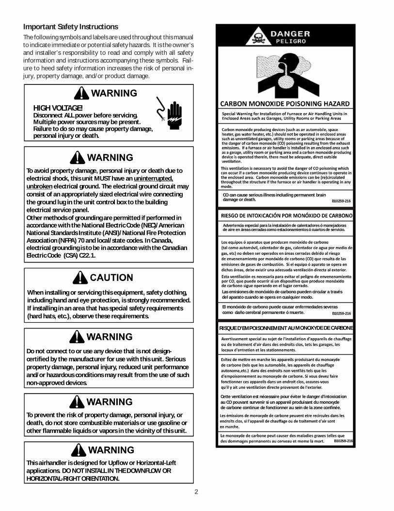
Important Safety InstructionsThe following symbols and labels are used throughout this manualto indicate immediate or potential safety hazards. It is the owner’sand installer’s responsibility to read and comply with all safetyinformation and instructions accompanying these symbols. Fail-ure to heed safety information increases the risk of personal in-jury, property damage, and/or product damage.
HIGH VOLTAGE!
Failure to do so may cause property damage,personal injury or death.
Multiple power sources may be present.Disconnect ALL power before servicing.
To avoid property damage, personal injury or death due to electrical shock, this unit MUST have an
electrical ground. The electrical ground circuit may consist of an appropriately sized electrical wire connecting the ground lug in the unit control box to the building electrical service panel.Other methods of grounding are permitted if performed in accordance with the National Electric Code (NEC)/American National Standards Institute (ANSI)/National Fire Protection Association (NFPA) 70 and local/state codes. In Canada, electrical grounding is to be in accordance with the Canadian Electric Code (CSA) C22.1.
uninterrupted, unbroken
When installing or servicing this equipment, safety clothing, including hand and eye protection, is strongly recommended. If installing in an area that has special safety requirements (hard hats, etc.), observe these requirements.
Do not connect to or use any device that is not design-certified by the manufacturer for use with this unit. Serious property damage, personal injury, reduced unit performance and/or hazardous conditions may result from the use of such non-approved devices.
To prevent the risk of property damage, personal injury, or death, do not store combustible materials or use gasoline or other flammable liquids or vapors in the vicinity of this unit.
This airhandler is designed for Upflow or Horizontal-Left applications. DO NOT INSTALL IN THE DOWNFLOW OR HORIZONTAL-RIGHT ORIENTATION.
B10259-216CO can cause serious illness including permanent braindamage or death.
Advertencia especial para la instalación de calentadores ó manejadoras de aire en áreas cerradas como estacionamientos ó cuartos de servicio.
B10259-216
El monóxido de carbono puede causar enfermedades severas como daño cerebral permanente ó muerte.
Las emisiones de monóxido de carbono pueden circular a travésdel aparato cuando se opera en cualquier modo.
B10259-216
RISQUE D'EMPOISONNEMENT AU MONOXYDE DE CARBONE
Cette ventilation est nécessaire pour éviter le danger d'intoxicationau CO pouvant survenir si un appareil produisant du monoxyde de carbone continue de fonctionner au sein de la zone confinée.

3
Product Identification
DAT Nominal Cooling Capacity
Model SeriesDAT
0904 - 90,000 Btuh (7 1/2 Tons)
1204 - 120,000 Btuh (10 Tons)
Product DescriptionWhen matched with DX11TA, DZ11TA, DX13SA and DZ13SA con-densers, this system complies with the minimum efficiency require-ments found in ASHRAE 90.1-2016. See the Daikin DX11TA,DZ11TA, DX13SA and DZ13SA specification sheets for details onthese condensers. For other Daikin condenser(s) that can bematched with this airhandler to obtain ASHRAE 90.1-2016 com-pliance, consult with your local distributor.The DAT series is intended for use with a room thermostat. Thisthermostat is not supplied with this equipment. Only thermostatsthat use 24 VAC control circuitry are to be used.
DAT0904 DAT1204Net Weight (Lbs.) 400 400
Shipping Weight (Lbs.) 430 430
Refrigerant R-410A R-410A
Blower Wheel (Dia x Width) 11X10 11X10
Blower Wheel Quantity 2 2
Motor Type Belt Drive Belt Drive
Motor Qty 1 1
Motor (HP) 2 2
Motor (RPM) 1750 1750
Motor Sheave Type
Motor Sheave Diameter (in) 1.9" - 2.9" 2.8" - 3.8"
Blower Wheel Pulley Type
Blower Wheel Pulley Dia (in) 5.9 5.9
Evaporator Coil Material
Face Area (Ft2) 10.0 10.0
Number of Rows 4 4
Suction Line Quantity 2 2
Suction Line Connection (in) * 1 1/8 1 1/8
Liquid Line Quantity 2 2
Liquid Line Connection (in)* 3/8 3/8
Metering Device
TXV Type
TXV Quantity 2 2*Note: Consult w ith the condenser specifications for suction and liquidline sizing.
Adjustable Variable Pitch
Fixed Diameter
Copper Tubes / Al Fins
Thermal Expansion Valve (TXV)
Non-adjustable (factory installed)
Unit InspectionUpon delivery, the unit is to be inspected for damage. Any dam-age must be reported immediately to the carrier. Do not installthis equipment if it is determined that the integrity or safety hasbeen compromised by freight damage.
Using the table “Model Identification” section check the equip-ment model number to ensure the unit is appropriately sized forthe condenser unit(s).
If an incorrect unit is supplied it must not be installed and it is tobe returned to the supplier. The manufacturer assumes no re-sponsibility for the installation of incorrect delivered units.
The evaporator coil contains a high-pressure inert gas holdingcharge.
Codes & RegulationsThis product is designed and manufactured to comply with na-tional codes. Installation in accordance with such codes and/orprevailing local codes/regulations is the responsibility of the in-staller. The manufacturer assumes no responsibility for equip-ment installed in violation of any codes or regulations.The United States Environmental Protection Agency (EPA) hasissued various regulations regarding the introduction and dis-posal of refrigerants. Failure to follow these regulations may harmthe environment and can lead to the imposition of substantialfines. Should you have any questions please contact the local of-fice of the EPA.
Replacement PartsWhen reporting shortages or damages, or ordering repair parts,give the complete product model and serial numbers as stampedon the product. Replacement parts for this product are availablethrough your contractor or local distributor. For the location ofyour nearest distributor consult the white business pages, the yel-low page section of the local telephone book or contact:
EQUIPMENT SUPPORTDAIKIN NORTH AMERICA LLC
19001 KERMIER ROADWALLER, TEXAS 7484
855-770-5678
If replacing an air handler, the system must be manufacturer ap-proved and Air-Conditioning, Heating, and Refrigeration Institute(AHRI) matched. NOTE: Installation of unmatched systems isstrongly discouraged.
Pre-Installation InstructionsCarefully read all instructions for the installation prior to installingproduct. Make sure each step or procedure is understood and anyspecial considerations are taken into account before starting in-stallation. Assemble all tools, hardware and supplies needed tocomplete the installation. Some items may need to be purchasedlocally. Make sure everything needed to install the product is onhand before starting.

4
LocationNOTE: Airhandlers are designed for indoor installation only.
When installing this airhandler in an enclosed area, such as a ga-rage/parking area, as with any carbon monoxide producing device(i.e. and automobile, space heater, water heater, etc.), insure thatthe area is properly ventilated.
The DAT airhandler is suitable for installation in multiple locationsincluding:
* Overhead (attic/mezzanine, etc.)* Closet/mechanical room
When installing this airhandler, consideration is to be given to mini-mize the length of refrigerant tubing. Also, do not install theairhandler in a location either above or below the condenser thatviolates the instructions provided with the condenser.The clearance from a combustible surface to the unit may be 0".However, service clearance is to take precedence. In addition al-low a minimum of 36" in front of the unit for service clearance.Allow sufficient clearance to remove the heater elements for ser-vice or replacement in heat kits when utilized in application.
When installing in an area directly over a finished ceiling (such asan attic), an emergency drain pan is required directly under theunit. See local and state codes for additional requirements.
When installing this unit in an area that may become wet, elevatethe unit with a sturdy, non-porous material.
In installations that may lead to physical damage (warehouse, in-dustrial sites, etc.), it is advised to install a protective barrier toprevent such damage.
DuctworkThis DAT air handler is designed for a complete supply and returnductwork system.
Do not operate this product without all the ductwork attached.
To ensure correct system performance, the ductwork is to be sizedto accommodate 375-425 CFM per ton of cooling with the staticpressure not to exceed .5" WC. Inadequate duct work that restrictsairflow can result in improper performance and compressor orheater failure. Ductwork is to be constructed in a manner thatlimits restrictions and maintains suitable air velocity. Ductwork isto be sealed to the unit in a manner that will prevent leakage.
Supply Ductwork and FlangesThe supply ductwork flanges are shipped loose and required to befield installed. See the following sketch for further details: Di-mensions are approximately 40" x 13-1/8".
Return DuctworkDO NOT TERMINATE THE RETURN DUCTWORK IN AN AREA THATCAN INTRODUCE TOXIC, OR OBJECTIONABLE FUMES/ODORS INTOTHE DUCTWORK. The return ductwork is to be introduced intothe air handler bottom (upflow configuration). The cabinet di-mensions are 48” x 24”.
Return Air FiltersEach installation must include a return air filter. This unit is fac-tory equipped with disposable return air filters. To ensure opti-mum performance, frequent filter replacement is advised. Seethe following table for the factory installed filter sizes.
Model Filter Size (in) Qty.
16 x 20 x 2 2
20 x 20 x 2 2
DAT0904 and
DAT1204
Electric HeatRefer to this manual in combination with the instructions pro-vided with the heat kit for the correct installation procedure.The electrical characteristics of the airhandler, the electric heatkit, and the building power supply must agree.The air handlers listed in this manual do not have factory installedelectric heat. Electric heat is available as an accessory. If install-ing this option, the ONLY heat kits that can be used are the AHKDseries.
AHKD MODELNUMBER
NOMINALKW
ELECTRICALCHARACTERISTICS STAGES
AHKD15-3 15 208-230/3/60 1
AHKD15-4 15 460/3/60 1
AHKD20-3 20 208-230/3/60 2
AHKD20-4 20 460/3/60 2
AHKD30-3 30 208-230/3/60 2
AHKD30-4 30 460/3/60 2
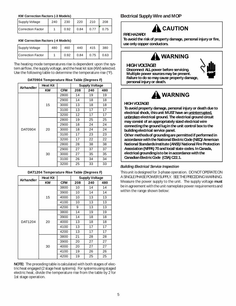
For all supply voltages, use the correction factors in the followingtables, multiplied by KW and (or) temperature rise to have cor-rected results.
5
Supply Voltage 240 230 220 210 208
Correction Factor 1 0.92 0.84 0.77 0.75
Supply Voltage 480 460 440 415 380
Correction Factor 1 0.92 0.84 0.75 0.63
KW Correction Factors (-3 Models)
KW Correction Factors (-4 Models)
The heating mode temperatures rise is dependent upon the sys-tem airflow, the supply voltage, and the heat kit size (KW) selected.Use the following table to determine the temperature rise (°F).
Heat KitKW CFM 208 240 480
2800 14 19 192900 14 18 183000 13 18 183100 13 17 173200 12 17 172800 19 25 252900 18 24 243000 18 24 243100 17 23 233200 17 22 222800 28 38 382900 27 37 373000 27 35 353100 26 34 343200 25 33 33
DAT0904
15
20
30
DAT0904 Temperature Rise Table (Degrees F)Supply VoltageAirhandler
Heat KitKW CFM 208 240 480
3800 10 14 143900 10 14 144000 10 13 134100 10 13 134200 9 13 133800 14 19 193900 14 18 184000 13 18 184100 13 17 174200 13 17 173800 21 28 283900 20 27 274000 20 27 274100 19 26 264200 19 25 25
DAT1204 Temperature Rise Table (Degrees F)
DAT1204
15
20
30
Airhandler Supply Voltage
NOTE: The preceding table is calculated with both stages of elec-tric heat engaged (2 stage heat systems). For systems using stagedelectric heat, divide the temperature rise from the table by 2 for1st stage operation.
Electrical Supply Wire and MOP
FIRE HAZARD!To avoid the risk of property damage, personal injury or fire, use only copper conductors.
HIGH VOLTAGE!
Failure to do so may cause property damage,personal injury or death.
Multiple power sources may be present.Disconnect ALL power before servicing.
HIGH VOLTAGE!To avoid property damage, personal injury or death due to electrical shock, this unit MUST have an
electrical ground. The electrical ground circuit may consist of an appropriately sized electrical wire connecting the ground lug in the unit control box to the building electrical service panel.Other methods of grounding are permitted if performed in accordance with the National Electric Code (NEC)/American National Standards Institute (ANSI)/National Fire Protection Association (NFPA) 70 and local/state codes. In Canada, electrical grounding is to be in accordance with the Canadian Electric Code (CSA) C22.1.
uninterrupted, unbroken
Building Electrical Service InspectionThis unit is designed for 3-phase operation. DO NOT OPERATE ONA SINGLE PHASE POWER SUPPLY. SEE THE PRECEDING WARNING.Measure the power supply to the unit. The supply voltage mustbe in agreement with the unit nameplate power requirements andwithin the range shown below:
6
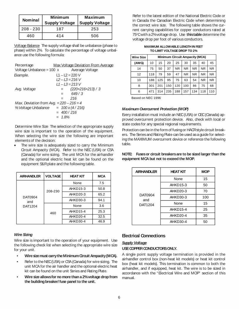
Nominal MinimumSupply Voltage
MaximumSupply Voltage
208 - 230 187 253460 414 506
Voltage Balance The supply voltage shall be unbalance (phase tophase) within 2%. To calculate the percentage of voltage unbal-ance use the following formula:
Percentage Max Voltage Deviation From AverageVoltage Unbalance = 100 x Average Voltage
Example. L1 – L2 = 220 VL2 – L3 = 216 VL1 – L3 = 213 V
Avg. Voltage = (220+216+213) / 3 = 649 / 3 = 216
Max. Deviation from Avg. = 220 – 216 = 4% Voltage Unbalance = 100 x (4 / 216)
= 400 / 216= 1.8%
Determine Wire Size The selection of the appropriate supplywire size is important to the operation of the equipment.When selecting the wire size the following are importantelements of the decision:• The wire size is adequately sized to carry the Minimum
Circuit Ampacity (MCA). Refer to the NEC (USA) or CSA(Canada) for wire sizing. The unit MCA for the airhandlerand the optional electric heat kit can be found on theequipment S&R plate and the following table.
AIRHANDLER VOLTAGE HEAT KIT MCA
None 7.5
AHKD15-3 50.8AHKD20-3 65.2
AHKD30-3 94.1None 3.6
AHKD15-4 25.3AHKD20-4 32.5AHKD30-4 46.9
DAT0904 and
DAT1204
208-230
460
Wire SizingWire size is important to the operation of your equipment. Usethe following check list when selecting the appropriate wire sizefor your unit.
• Wire size must carry the Minimum Circuit Ampacity (MCA).• Refer to the NEC (USA) or CSA (Canada) for wire sizing. The
unit MCA for the air handler and the optional electric heatkit can be found on the unit Series and Rating Plate.
• Wire size allows for no more than a 2% voltage drop fromthe building breaker/fuse panel to the unit.
Refer to the latest edition of the National Electric Code orin Canada the Canadian Electric Code when determiningthe correct wire size. The following table shows the cur-rent carrying capabilities for copper conductors rated at75oC with a 2% voltage drop. Use this table determine thevoltage drop per foot of various conductors.
Wire Size
(AWG) 10 15 20 25 30 35 40 45
14 75 50 37 NR NR NR NR NR
12 118 79 59 47 NR NR NR NR
10 188 125 95 75 63 54 NR NR
8 301 201 150 120 100 86 75 68
6 471 314 235 188 157 134 118 110
Based on NEC 1996
Minimum Circuit Ampacity (MCA)
MAXIMUM ALLOWABLE LENGTH IN FEETTO LIMIT VOLTAGE DROP TO 2%
Maximum Overcurrent Protection (MOP)Every installation must include an NEC (USA) or CEC (Canada) ap-proved overcurrent protection device. Also, check with local orstate codes for any special regional requirements.Protection can be in the form of fusing or HACR style circuit break-ers. The Series and Rating Plate can be used as a guide for select-ing the MAXIMUM overcurrent device or reference the followingtable.
NOTE: Fuses or circuit breakers are to be sized larger than theequipment MCA but not to exceed the MOP.
AIRHANDLER HEAT KIT MOP
None 15
AHKD15-3 50
AHKD20-3 70AHKD30-3 100
None 15
AHKD15-4 25AHKD20-4 35
AHKD30-4 50
DAT0904 and
DAT1204
Electrical ConnectionsSupply VoltageUSE COPPER CONDUCTORS ONLY.A single point supply voltage termination is provided in theairhandler control box (non-heat kit models) or heat kit controlbox (heat kit models). This termination is common to both theairhandler, and if equipped, heat kit. The wire is to be sized inaccordance with the “Electrical Wire and MOP” section of thismanual.

7
Air Handler Only (Non-Heat Kit Models)Supply wire is to be routed through conduit from the service dis-connect box to the unit. The airhandler is equipped with a knock-out suitable for ¾” conduit. The following diagram illustrates thesupply voltage hook-up.
Heater Kit ModelsWhen a heater kit is used the system uses a single point wiringhook-up. The supply wire is to be routed through conduit fromthe service disconnect box to the heater kit. The heat kit isequipped with a knockout suitable for ½” or ¾” conduit depen-dent on the KW. The supply voltage is to be installed on the termi-nal block located in the heater kit control box.
The heater kit is factory equipped with the supply and low voltagewires for the airhandler. The low voltage connection from theheater kit is provided through a multi-pin plug which connects to amating plug in the airhandler. The high voltage connections are tobe made at the air handler contactor. These wires are to be routedthrough the pipe nipples supplied with the heater kit as shown inthe illustration:
GND
SUPPLY VOLTAGE TO THIS
CONTACTOR
Low Voltage ConnectionsThe 24V-control voltage connects the airhandler to the roomthermostat and condenser. These models are designed for usewith a two-stage thermostat. Low voltage wiring is to be copperconductors, and be a minimum of 18AWG. A provision on thecabinet side to accept the low voltage wiring is provided. See thesystem wiring diagram for typical low voltage connections.
Heat Kit InstallationInspect for Shipping Damage. The heat kit is an optional acces-sory that is shipped separately from the air handler. Inspect theheat kit for damage and report any damage to the carrier and/ordistributor. Do not install this accessory if it is determined thatthe integrity or safety has been compromised by freight damage.
Check the Nameplate. From the heat kit nameplate check thefollowing:
· The model number agrees with the approved models (see the“Electric Heat” section of this manual).
· The correct size (kW)· Electric characteristics, voltage and phase, agree with the
building electrical supply.
Attaching the Heat Kit The heat kit attaches directly to the toppanel (when viewed in the upflow position) of the airhandler. Donot screw the heat kit into the duct flanges. See the followingdrawing for details:
8
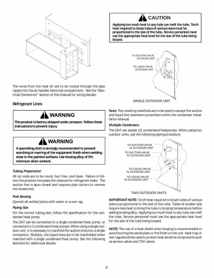
The wires from the heat kit are to be routed through the pipenipple into the air handler electrical compartment. See the “Elec-trical Connection” section of this manual for wiring details.
Refrigerant Lines
This product is factory-shipped under pressure. Follow these instructions to prevent injury.
A quenching cloth is strongly recommended to prevent scorching or marring of the equipment finish when welding close to the painted surfaces. Use brazing alloy of 5% minimum silver content.
Tubing PreparationAll cut ends are to be round, burr free, and clean. Failure to fol-low this practice increases the chances for refrigerant leaks. Thesuction line is spun closed and requires pipe cutters to removethe closed end.
Post BrazingQuench all welded joints with water or a wet rag.
Piping SizeFor the correct tubing size, follow the specification for the con-denser/heat pump.The DAT can be connected to a single condenser/heat pump, orconnected to 2 condensers/heat pumps. When using a single out-door unit, it is necessary to manifold the suction lines into a singleconnection. Similarly, the liquid lines are to be manifolded whenmatched with a single condenser/heat pump. See the followingsketches for additional details.
Applying too much heat to any tube can melt the tube. Torchheat required to braze tubes of various sizes must beproportional to the size of the tube. Service personnel mustuse the appropriate heat level for the size of the tube beingbrazed.
CAUTION
SINGLE OUTDOOR UNIT
TO SUCTION VALVEOUTDOOR UNIT
TO LIQUID VALVEOUTDOOR UNIT
Note: The resulting manifolds are to be sized to accept the suctionand liquid line diameters prescribed within the condenser Instal-lation Manual.
Multiple CondensersThe DAT can accept (2) condensers/heatpumps. When using twooutdoor units, use the following piping procedure:
TO SUCTION VALVE#1 OUTDOOR UNIT
TO SUCTION VALVE#2 OUTDOOR UNIT
TO LIQUID VALVE#1 OUTDOOR UNIT
TO LIQUID VALVE#2 OUTDOOR UNIT
TWO OUTDOOR UNITS
IMPORTANT NOTE: Torch heat required to braze tubes of varioussizes is proportional to the size of the tube. Tubes of smaller sizerequire less heat to bring the tube to brazing temperature beforeadding brazing alloy. Applying too much heat to any tube can meltthe tube. Service personnel must use the appropriate heat levelfor the size of the tube being brazed.
NOTE: The use of a heat shield when brazing is recommended toavoid burning the serial plate or the finish on the unit. Heat trap orwet rags should be used to protect heat sensitive components suchas service valves and TXV valves.
9
0 1 2 3 4 50.1 - 4472 41340.2 - 4119 37760.3 - 4322 3936 35610.4 - 4406 3955 3683 33040.5 - 4427 4026 3761 3402 29590.6 - 4265 3845 3422 3094 25810.7 4347 3899 3618 3100 2722 -0.8 3964 3594 3266 2742 2512 -0.9 3710 3233 2835 2470 - -
Static Pressure
DAT1204Sheave Turns Open
Belt TensionThe belt tension is to be checked at the time of installation andafter a “run in” period of about 24 hours. To perform the mea-surement, it is suggested that a “Belt Tension Gauge” (availablefrom most belt manufacturers) be used. The force required todeflect the belt 7/32" (at the midpoint) should be 3.6 ± 0.3 pounds.Regular MaintenanceThe only item to be maintained on a regular basis by the user isthe circulating air filter(s). Filter should be cleaned or replacedregularly.
HIGH VOLTAGE!Disconnect ALL power before servicing or installing this unit. Multiple power sources may be present. Failure to do so may cause property damage, personal injury or death.
Routine maintenance is essential for trouble free operation of thisAirhandler. A few preseason checks can eliminate costly repairsand down time.
A certified service technician must perform all services mentionedbelow.
1. Check and change air filters as needed
2. Check, adjust or replace belts and check sheaves for properoperation.
3. Clean the evaporator coil and check for duct leaks.
4. Check for proper charge and (or) for refrigerant leaks.
If these few precautions are observed and maintained, thisAirhandler can provide years of trouble free service.
Evaporator Coil TXVNote: Thermal Expansion Valve (TXV) Bulb is not permanentlyconnected to the suction from the factory. After suction andliquid line tubing is brazed in the field, the TXV bulb must beattached and insulation to the suction line(s) inside the cabi-net at the 10 or 2 o’clock position. This location will be differ-ent depending on the orientation of the unit, vertical or hori-zontal. Always locate the TXV bulb on the top of the suctiontube at 10 or 2 o’clock.
Check condensing unit / heat pump instructions for chargingmethod.
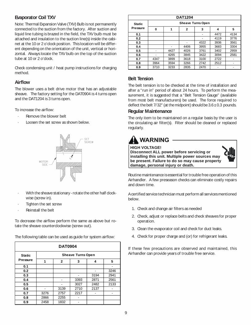
AirflowThe blower uses a belt drive motor that has an adjustablesheave. The factory setting for the DAT0904 is 4 turns openand the DAT1204 is 3 turns open.
To increase the airflow:· Remove the blower belt· Loosen the set screw as shown below.
· With the sheave stationary - rotate the other half clock-wise (screw in).
· Tighten the set screw· Reinstall the belt
To decrease the airflow perform the same as above but ro-tate the sheave counterclockwise (screw out).
The following table can be used as guide for system airflow:
1 2 3 4 50.1 -0.2 - 32460.3 - 3194 29410.4 - 3393 2871 25610.5 - 3027 2482 21330.6 - 3139 2710 2137 -0.7 3276 2757 2217 - -0.8 2866 2255 -0.9 2458 1832 -
DAT0904
Static Pressure
Sheave Turns Open

10Wiring is subject to change. Always refer to the wiring diagram on the unit for the most up-to-date wiring.
HIG
H V
OLT
AG
E!D
ISC
ON
NEC
T A
LL P
OW
ER B
EFO
RE
SER
VIC
ING
OR
INST
ALL
ING
TH
ISU
NIT
. M
ULT
IPLE
PO
WER
SO
UR
CES
MAY
BE
PRES
ENT.
FA
ILU
RE
TOD
O S
O M
AY C
AU
SE P
RO
PER
TY D
AM
AG
E, P
ERSO
NA
L IN
JURY
OR
DEA
TH.
Wiring Diagram

11
WA
RN
ING
HIG
H V
OLT
AG
E!D
ISC
ON
NEC
T A
LL P
OW
ER B
EFO
RE
SER
VIC
ING
OR
INST
ALL
ING
TH
ISU
NIT
. M
ULT
IPLE
PO
WER
SO
UR
CES
MA
Y B
E PR
ESEN
T. F
AIL
UR
E TO
DO
SO
MA
Y C
AU
SE P
RO
PER
TY D
AM
AG
E, P
ERSO
NA
L IN
JUR
Y O
R D
EATH
.
Wiring Diagram
Wiring is subject to change. Always refer to the wiring diagram on the unit for the most up-to-date wiring.
BL
----
-----
------
BLU
EB
R --
-----
------
-- B
RO
WN
OR
----
-----
------
OR
AN
GE
PU
-----
-----
-----
PU
RP
LER
D --
-----
-----
--- R
EDW
H --
-----
-----
-- W
HIT
E
C
G
R
W1
W2
Y1
Y2
O
RD
BL
GR
WH
BR
YL
PU
OR
CO
LOR
CO
DE
BK
----
-----
------
BLA
CK
M1
M2
1 2 3
4 5 6
C460575
TR
24V
HIG
HE
MLO
W
L3T3
CL2 L1
T2 T1
BC
1
L3T3
CL2 L1
T2 T1
BC
2
RD
BK
GR
GR
GN
D
S1
S2
RD
PU
YL
YL
BR
WH
YL
BL
BL
PU
PU
OR
RD
BK
OR
BR
1
BR
2
53
21
4NC 5
3
21
4
YL
BL
BL
PU
BLGY
YL
208240
BLW
HOR
BK B
KB
K
BL
BL
GR
BL
GR
PK
BK
OR
BK
WH
REL
AY(S
EQU
ENC
ER)
RD
RD
OR
GR
RD
THE
RM
OST
AT
L1 L2 L3
SUPP
LY
YL
-----
------
----
YE
LLO
WP
K --
-----
-----
--- P
INK
GR
-----
-----
-----
- GR
EE
N
WIR
ING
CO
DE
FAC
TOR
Y W
IRIN
GH
IGH
VO
LTAG
ELO
W V
OLT
AG
EO
PTI
ON
AL
HIG
H V
OLT
AG
EFI
ELD
WIR
ING
HIG
H V
OLT
AGE
LOW
VO
LTA
GE
RC
GW
1W
2Y1
Y2
O
WH
BLB
R
YL
PK
PU
RD
GR
WH
BL
BL
BL
RD
WH
BR
YL
PU
OR
OR
OR
WH
WH
WH
WH
BL
BL
BL
BLB
L
YL
YL
PU
PU
TOC
ON
DE
NS
OR
TOC
ON
DEN
SO
R
H
eat P
ump
Onl
y
VOLT
AGE
OR O
R
0140
L036
95
CO
MPO
NEN
T LE
GEN
DB
C
BLO
WE
R C
ON
TAC
TOR
BR
B
LOW
ER
RE
LAY
EM
E
VAP
OR
ATO
R M
OTO
RG
ND
E
QU
IPM
EN
T G
RO
UN
DP
LF
FE
MA
LE P
LUG
/ C
ON
NE
CTO
RTB
1
TER
MIN
AL
BLO
CK
(24V
SIG
NA
L)TR
T
RAN
SFO
RM
ER

12
Our continuing commitment to quality products may mean a change in specifications without notice.© 2013-2014, 2018
5151 San Felipe St., Suite 500, Houston, TX 77056www.daikinac.com
Top Related