


Languages
Pages
Legal


Code Generation from Cinderella-SDL
to Embedded Platforms
by
Leiming Chen
Thesis in partial fulfilment of the degree of
Master in Technology in
Information and Communication Technology
Agder University College
Faculty of Engineering and Science
Grimstad
Norway
May 2007

Code Generation from Cinderella-SDL to Embedded Platforms
I
Abstract
SDL (Specification and description language) is increasingly adopted by many companies and
researchers. Its simplicity and object-oriented structure can greatly ease the workload for them.
However, the lack of concretization makes SDL not applicable when it comes to real-world
implementation.
AvR is a micro-controller which can be a platform to carry out real-world implementation. The
micro kernel REFLEX of the AvR operating system adopted many SDL features. Here, I present a
new code generator which can transform SDL systems into executable C programs. It is built
specially for SDL REFLEX which is a micro kernel for the real time operating system of AVR.
We analyzed some existing code generators like C-micro, C-Advanced/Basic, ConTraSt and
Cinderella-SITE. Then, we gathered their advantages and promoted them into our solution.
All the components which are helpful in building systems have been analyzed and classified; only
necessary elements are kept in the transformation. We also provide the corresponding techniques
used in the transformation. One test example, which is frequently used in literature, has been
executed on AvR platform. The name of the example is “tank”.
We give the name CGFR (“code generator for SDL REFLEX”) to the generator and Config to the
supporting header generator. They can be integrated under Cinderella SDL as plug-ins.
Keywords: code generator, embedded platform, plug-in, transformation, CGFR, SDL.

Code Generation from Cinderella-SDL to Embedded Platforms
II
Preface
This thesis was written for Agder University College, Faculty of information and communication
technology. The work has been carried out in the period January 2007 and May 2007.
First of all, we would like to thank Professor Dr. Andreas Prinz, our supervisor at Agder
University College, for excellent supervision and guidance throughout the project period. The
thesis has been developed in co-operation with Cinderella Company in Copenhagen, Denmark. In
this context we will also thank our supervisors Anders Olsen, Paul B Anderson and Torstein
Wroldsen. Finally we would like to thank Head of Studies, Stein Bergsmark, for his contributions.
Grimstad, May 2007.
————————————————————————————————————————————————————————————————
Leiming Chen

Code Generation from Cinderella-SDL to Embedded Platforms
III
Table of Contents
Abstract............................................................................................................................................ I
Preface.............................................................................................................................................II
Table of Contents.......................................................................................................................... III
Chart List........................................................................................................................................V
Table List ........................................................................................................................................V
Figure list ........................................................................................................................................V
Chapter 1 Introduction.............................................................................................................1
1.1 General ......................................................................................................................1
1.2 Problem Description..................................................................................................2
1.3 Thesis definition........................................................................................................3
1.4 Delimitation ..............................................................................................................3
Chapter 2 Background..............................................................................................................4
2.1 Overview of SDL ......................................................................................................4
2.1.1 History...............................................................................................................4
2.1.2 Features .............................................................................................................5
2.1.3 SDL Elements ...................................................................................................6
2.2 REFLEX..................................................................................................................10
2.2.1 Overview.........................................................................................................10
2.2.2 Kernel Features ...............................................................................................10
Chapter 3 Analysis of Some Existing Code Generators.......................................................12
3.1 C-micro SDL to C compiler ....................................................................................12
3.2 C-advanced/ C-basic ...............................................................................................14
3.3 ConTraST................................................................................................................16
3.4 Cinderella SITE.......................................................................................................18
3.5 Comparison among Existing Code Generators .......................................................19
Chapter 4 Design Consideration............................................................................................20
4.1 Motivation...............................................................................................................20
4.2 Decision Making .....................................................................................................20
4.3 Elements Classification and Analysis .....................................................................21
Chapter 5 Transformation Description .................................................................................23
5.1 Introduction.............................................................................................................23
5.2 Element Mapping....................................................................................................23
5.3 Structural Elements Transformation........................................................................23
5.3.1 System.............................................................................................................24
5.3.2 Block ...............................................................................................................25
5.3.3 Process ............................................................................................................26
5.3.4 Procedure ........................................................................................................27
5.4 Definition Elements Transformation.......................................................................28
5.4.1 Signal Definition .............................................................................................28
5.4.2 Data Definition................................................................................................28
5.4.3 Variable Declaration........................................................................................30

Code Generation from Cinderella-SDL to Embedded Platforms
IV
5.5 Behavior Elements Transformation.........................................................................30
5.5.1 Start .................................................................................................................30
5.5.2 State.................................................................................................................31
5.5.3 Trigger.............................................................................................................32
5.5.4 Free Actions ....................................................................................................33
5.5.4.1 Action.......................................................................................................33
5.5.4.2 Transition End ..........................................................................................35
5.6 Expression...............................................................................................................36
Chapter 6 Transformation Technique ...................................................................................39
6.1 General ....................................................................................................................39
6.2 Overview of the API................................................................................................39
6.3 Element Extraction..................................................................................................40
6.4 Principle ..................................................................................................................42
Chapter 7 System Test.............................................................................................................43
7.1 Results of Different Stages......................................................................................43
7.2 Test Example...........................................................................................................44
Chapter 8 Discussion...............................................................................................................46
8.1 Major Findings........................................................................................................46
8.2 Comparison with Existing C Code Generators .......................................................46
8.3 Comparison with Manually Written Target Code....................................................47
8.4 Alternatives .............................................................................................................47
Chapter 9 Conclusion and Future Work...............................................................................49
9.1 Conclusion ..............................................................................................................49
9.2 Future Work.............................................................................................................49
ABBREVIATIONS .......................................................................................................................51
REFERENCE................................................................................................................................52
Appendix A – User Manual ..........................................................................................................54
Execution Steps.......................................................................................................................54
User Notifications ...................................................................................................................54
Error Handling ........................................................................................................................55
Appendix B – Example Tanker ....................................................................................................56
Manually Written Code...........................................................................................................56
Generated Code.......................................................................................................................62

Code Generation from Cinderella-SDL to Embedded Platforms
V
Chart List
Chart 3-1 Existing Code Generators Comparison .........................................................................19
Chart 7-1 Process trend..................................................................................................................44
Chart 7-2 Comparison between Generated and Manually Written Codes .....................................45
Chart 8-1 Comparisons between CGFR and Existing Code Generators........................................47
Chart 8-2 Comparisons among Alternatives ..................................................................................48
Table List
Table 3-1 C-micro Generated Files ................................................................................................13
Table 3-2 C-Advanced/Basic Generated Files................................................................................14
Table 4-1 Workflow........................................................................................................................21
Table 5-1Transformation symbols ..................................................................................................23
Figure list
Figure 1-1: Work Principle for CGFR..............................................................................................2
Figure 2-1 SDL Design Methodology..............................................................................................5
Figure 2-2 System-Environment Interaction ....................................................................................7
Figure 2-3 SDL Scope Unit Structure ..............................................................................................7
Figure 2-4 SDL symbols ..................................................................................................................8
Figure 2-5 Work Principle for Reflex.............................................................................................10
Figure 4-1 SDL Element Structure.................................................................................................22
Figure 5-1 System Syntax Diagram ...............................................................................................24
Figure 5-2 Block Syntax Diagram .................................................................................................25
Figure 5-3 Process Syntax Diagram...............................................................................................26
Figure 5-4 Procedure Syntax Diagram...........................................................................................27
Figure 5-5 Procedure Parameter Syntax Diagram..........................................................................28
Figure 5-6 Signal Syntax Diagram.................................................................................................28
Figure 5-7 Syntype Syntax Diagram..............................................................................................29
Figure 5-8 Synonym Syntax Diagram............................................................................................29
Figure 5-9 Newtype Syntax Diagram.............................................................................................29
Figure 5-10 Variable Syntax Diagram............................................................................................30
Figure 5-11 Timer Syntax Diagram................................................................................................30
Figure 5-12 Behavior Element Syntax Diagram ............................................................................30
Figure 5-13 Start Syntax Diagram..................................................................................................31
Figure 5-14 State Syntax Diagram .................................................................................................31
Figure 5-15 External State Syntax Diagram...................................................................................31
Figure 5-16 Input Syntax Diagram.................................................................................................32

Code Generation from Cinderella-SDL to Embedded Platforms
VI
Figure 5-17 External Syntax Diagram1..........................................................................................32
Figure 5-18 External Syntax Diagram2..........................................................................................32
Figure 5-19 Save Syntax Diagram .................................................................................................33
Figure 5-20 External Save Syntax Diagram...................................................................................33
Figure 5-21 Output Syntax Diagram..............................................................................................33
Figure 5-22 Task Syntax Diagram1................................................................................................34
Figure 5-23 Task Syntax Diagram2................................................................................................34
Figure 5-24 Set Syntax Diagram....................................................................................................34
Figure 5-25 Reset Syntax Diagram ................................................................................................34
Figure 5-26 Procedure Call Syntax Diagram .................................................................................34
Figure 5-27 Create Syntax Diagram...............................................................................................35
Figure 5-28 Decision Syntax Diagram...........................................................................................35
Figure 5-29 Decision Question Syntax Diagram............................................................................35
Figure 5-30 Decision Answer Syntax Diagram..............................................................................35
Figure 5-31 Label Syntax Diagram................................................................................................35
Figure 5-32 Join Syntax Diagram ..................................................................................................36
Figure 5-33 Connector Syntax Diagram ........................................................................................36
Figure 5-34 Stop Syntax Diagram..................................................................................................36
Figure 5-35 Return Syntax Diagram ..............................................................................................36
Figure 5-36 Infix-expression Syntax Diagram...............................................................................36
Figure 5-37 Parenthesis-expression Syntax Diagram.....................................................................37
Figure 5-38 Operator-application Syntax Diagram........................................................................37
Figure 5-39 Imperative-operator Syntax Diagram .........................................................................37
Figure 5-40 Conditional-expression Syntax Diagram....................................................................37
Figure 6-1 Work Principle for SDL API.........................................................................................42

Code Generation from Cinderella-SDL to Embedded Platforms
Leiming Chen 1 ©May 2007
Chapter 1 Introduction
1.1 General
From the very early stage of the computer technology until now, tremendous accelerations have
been made by software engineers regarding the development time and language complexity for the
different programming languages. Nowadays, in order to survive in this fast-paced and
competitive world, manufacturers are forced to deliver more complex and complete systems in
less time, with fewer staff and higher quality. This increases the responsibility for software
designers to design and deliver these systems as efficient as possible. At his time, the abstraction
of languages has increased from assembly language to high-level languages up to graphical
models, and the abstraction has moved from the system solution space toward the application
problem space. This trend can increase productivity, fulfill the need for constructing larger
applications and understanding complex systems. In this climate, model-driven development is
used to adopt a more visual, automated and reliable development process. Its capability for
generating code from object models offers additional help for keeping pace.
The model-driven methods can help developers analyze and understand a system in a great extent.
In model-driven technology, an important proportion to reduce the complexity of the rapid
development is using software automation tools. Design automation in general needs a formal
system description to capture both functional and non-functional requirements, and then
model-based code generation can produce application target code automatically from graphical
models of system behavior or architecture. Since a lot of advantages have been found in using this,
development tools are moving to model-based development gradually to raise the level of
abstractions.
However, until now, the model-driven methods have a common bottleneck lies in software
automation. Because of this shortcoming, the benefit of object modeling can barely live though the
entire products life circle without the automatic code generation. The pressure from customers
tends to sharp the trend of changing the source code directly, resulting in out of date models.
Generating code from object models still retains less use. Model-based code generation continues
to be a long term trend in development tools. However, as time goes on, the enduring nature
suggests that model based code generation is inevitable.
As one of the most successful model-driven languages, SDL has been evolving to a fairly useful
description language offering a multitude of different object-oriented features over the past 30
years. However, not all features are necessarily required to specify SDL systems, and especially in
embedded systems, the resulting waste of resources can be avoided. With SDL-2000 a formal
semantics based on Abstract State Machine (ASM) was introduced, eliminating the ambiguities
that come with the informal language definition. Additionally, the precise mathematical
formalisms of ASMs, which are used to describe the formal semantics, provide a rigorous basis for

Code Generation from Cinderella-SDL to Embedded Platforms
Leiming Chen ©May 2007 2
compilers and runtime environments.
1.2 Problem Description
Manually writing code with the drawn system in SDL doubles workload, so automatic code
generation from SDL is necessary because it can greatly ease the complexity and time consumed
on this. There are already some code generators for embedded systems exist; however, none of
them is designed for AvR micro chip family. Since an existing micro kernel SDL REFLEX has
been developed to support SDL notations in AVR chip family, the need for code generators which
can generate code based on the REFLEX libraries is urgent.
SDL is supported by several commercial tools. HiA has academic relation with Cinderella
Company. Furthermore, Cinderella SDL is an easy and useful SDL tool, it provides the self-create
plug-in for users, and to use the Cinderella SDL API to transform the diagram into codes is much
easier than read diagrams directly. So it is a good choice to choose Cinderella SDL as running
environment to generate the implementation code for based on the REFLEX libraries.
In this paper, Cinderella SDL is used as a runtime environment to transform and compile the
system models derived from the formal semantics of SDL-92 into C code with the developed real
time operating system for AvR micro chip. The name is given as CGFR which means code
generator for SDL REFLEX. This transformation retains the specified system structure and
generates understandable code that is a bit similar to the SDL/PR syntax. This, together with the
created real time operating system for embedded platform provides system execution. The basic
principle for CFGR is in Figure 1-1
Figure 1-1: Work Principle for CGFR
Users of the CGFR are supposed to be the students in HIA for academic study. They are supposed
Code Generation from Cinderella-SDL to Embedded Platforms
Leiming Chen ©May 2007 3
to have the basic knowledge of SDL and C language.
1.3 Thesis definition
Cinderella is a tool to display high-level SDL specifications. In order to execute these
specifications, they have to be turned into C code. In the master topic 30 of 2004, a real time
operating system for embedded platforms was built in C. This operating system provides SDL
primitives, such that an easy transformation from SDL to this operating system is possible.
This task is to use this SDL operating system and to generate code directly and automatically from
the Cinderella SDL tool and/or the Eclipse SDL plug-in produced at HiA. The restrictions in the
operating systems have to be taken into account, and a mostly direct transformation is to be
generated. If possible, the code generation is to be given in a high-level formalism like QVT.
1.4 Delimitation
In this project, we try to build a code generator which can generate code automatically from the
SDL diagram designed system. The code will be implemented with the support of REFLEX.
The support functions of REFLEX are not in our concern. If some functions do not support the
implementation or even are not exist, we need to find other ways to solve, not to change REFLEX.
The instructions in user manual shows how to compile and execute the generated code on AvR
micro-chip, however, the tool itself will not make the generated files executed automatically. This
tool is a pure code generator without any extra support. Users who want to use it need to
implement or change other steps by themselves.
Code Generation from Cinderella-SDL to Embedded Platforms
Leiming Chen ©May 2007 4
Chapter 2 Background
2.1 Overview of SDL
2.1.1 History
SDL is a Specification and Description Language. It is standardized as ITU (International
Telecommunication Union) Recommendation Z.100. The purpose of SDL is Provide a language
for unambiguous specification and description of the behavior of telecommunications systems.
The key features of the language are:
1. the ability to be used as a wide spectrum language from requirements to implementation
2. suitability for real-time, stimulus-response systems
3. presentation in a graphical form
4. a model based on communicating processes (extended finite state machines)
Although SDL is widely used in the telecommunications field, it is also now being applied to a
diverse number of other areas ranging over aircraft, train control, medical and packaging systems.
SDL is a general purpose description language for communicating systems. The basis for
description of behavior is communicating Extended State Machines that are represented by
processes. Communication is represented by signals and can take place between processes or
between processes and the environment of the system model. Some aspects of communication
between processes are closely related to the description of system structure. An Extended State
Machine consists of a number of states and a number of transitions connecting the states. The
machine starts in a transition leading to an initial state.
The language has been evolving since the first Z.100 Recommendation in 1980 with updates in
1984, 1988, 1992, 1996 and 1999. Object oriented features were included in the language in 1992.
This was extended in the latest version (SDL-2000) to give better support for object modeling and
for code generation. [1]
Stability of the SDL language is an important attribute to users, and SDL-92 was effectively a
superset of SDL-88. Therefore, any SDL that conforms to SDL-88 was also (with a few
exceptions) valid SDL-92. However, SDL-92 has many advantages in the way that systems can be
structured using object features of the language, and the most popular tools now support SDL-92
features. [1]
For SDL-2000, the opportunity was taken to remove some features that were not strongly
supported by tools. Object modeling in SDL was strengthened and better support given for
programming directly in SDL. In particular the data model was revised to give such features as
global data and referenced data objects. The structuring features (blocks and processes) were
harmonized into an agent concept. Support for ASN.1 was strengthened so that the use of ASN.1
Code Generation from Cinderella-SDL to Embedded Platforms
Leiming Chen ©May 2007 5
modules with SDL no longer requires any change main body of the language. [1]
Since 1999 there have been a few maintenance issues of the defining documents but SDL-2000
itself has not really changed. The language is being reviewed again starting in 2004 and the major
influence is likely to be UML2.0. [1]
2.1.2 Features
SDL is a modeling language which helps designers express and verify their design ideas in an
adequate way. This means that the language is expressive and unambiguous; it has
platform-independent, operational semantics and adequate support for modularization. The
objectives of SDL are:
1. formal description technique
2. easy to understand both for creators (direct users) and viewers (“non constructors” of
specifications) (graphical representation)
3. object oriented language
4. independent of design paradigm (e.g. functions or object oriented)
5. independent of implementation (language, operating system, and hardware)
Since SDL has evolved into a complete language, and gradually achieved the objectives, SDL
greatly improves the success rate in software building. And both the standard text representation
can greatly improve the portability of different graphical representation built with different SDL
tools.
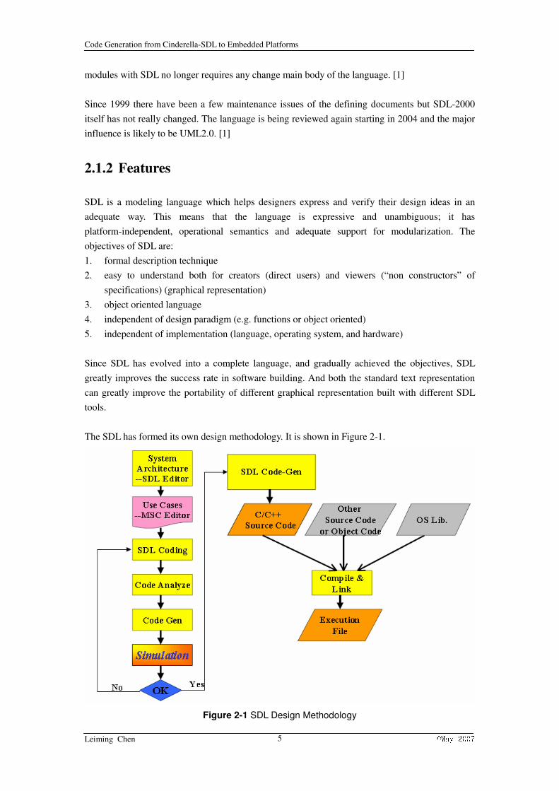
The SDL has formed its own design methodology. It is shown in Figure 2-1.
Figure 2-1 SDL Design Methodology
Code Generation from Cinderella-SDL to Embedded Platforms
Leiming Chen ©May 2007 6
SDL adopted object-oriented method in implementing and this can improve the productivity,
quality and reusability. Auto code generation is one of the important approaches to achieve the
demands. It can raise the level of abstraction at which developers can work because of the moving
trend towards model-based development of tools.
Now, SDL has grown into one of the most successful formal techniques used with widespread
usage throughout the software and the telecommunication industries. Part of the reasons for its
general adoption is its intuitive graphical notation and excellent tool support. The tool support
typically offers capabilities to analyze, design, implement and subsequently test systems, often
using combinations of interrelated notations together with SDL such as Message Sequence Charts.
2.1.3 SDL Elements
Simply speaking, an SDL system can be viewed as process instances which communicate by
sending signals to each other or to environment. Each single process can be described as an
autonomous finite state machine, working concurrently with other processes, cooperating with
them or environment through signals. A state is the only location where input can trigger a
transition in SDL. The process performs transitions depending on the inputs. Before the process
finally moves to a new state or same state, many transitions may occur.
However, SDL has grown into a complete language and many new notations have been introduced
into SDL to make it more object-oriented. The basic components of SDL are categorized and
listed below:
1. architecture
- system, block
2. behavior
- processes
3. communication
- signals and channels
4. data
- abstract data types
Here, we will introduce the basic elements in SDL step by step.
In order to provide a complete specification of a given system, a SDL-system specification needs
to be given. A SDL-system is the outermost agent that communicates with the environment. The
environment of the system is everything in the surroundings that communicate with the system in
an SDL-like way in Figure 2-2.

Code Generation from Cinderella-SDL to Embedded Platforms
Leiming Chen ©May 2007 7
Figure 2-2 System-Environment Interaction
A system is a set of blocks, block sets and channels. Blocks and block sets are connected with
each other or with the environment of the system by means of channels. A channel is a one-way or
two-way directed connection. It is characterized by the signals that it may carry.
A SDL-system must define the interfaces to communicate with other components. It has a
hierarchical structure. A complete system must contain at least one block. A block must contain at
least one process or block, and blocks and processes must not be mixed in one block. It is shown
in Figure 2-3.
Figure 2-3 SDL Scope Unit Structure
A block is a container of processes (or of blocks). Processes of a block are contained in process
sets that are connected by signal routes. A block is created as part of creation of the enclosing
block or system. All blocks are created as part of the system creation.
Processes are the actors of SDL systems. An SDL process represents an extended finite state
machine. Processes can be defined with an initial and a maximum number of instances. SDL
processes can communicate by means of asynchronous message passing with other processes.
The SDL process may contain a list of elements and their properties. It includes process name,

Code Generation from Cinderella-SDL to Embedded Platforms
Leiming Chen ©May 2007 8
formal parameters, local variables, time and timers and the graphical representation of a FSM. The
behaviors of the process are described in the graphical representation of the FSM. In SDL, the
FSM is extended with data processing.
Process instances can be created and terminated dynamically. A process is activated by means of
an arriving signal. At the end of a transition, the next state is entered. Each SDL process maintains
a set of intrinsic variables which are of the predefined data type PId (Process Identity).
In the graphical representation, FSM provides all details of the behavior of the process. FSM is
composed of certain process symbols. They are shown in Figure 2-4.
Figure 2-4 SDL symbols
General
A process instance is created either initially or dynamically with a start symbol. When a process
instance has been created, the execution of the process body starts by the execution of the
transition that follows the start symbol.
The states can determine how the process instance reacts to an input. The process states are the
only locations where inputs can trigger the transitions.
Triggers
An input is the acceptance of a signal by a process in a certain situation (state). When a signal is
accepted it is also consumed. An input symbol connects a state to the actions which the process
shall take after consuming the signal mentioned in the input symbol. How to store the values is
also conveyed with signal inside the input symbol.
In some cases handling of some signals has higher priority than handling of other signals. Signals
which take priority in a state are placed inside priority input symbols. If a state has both ordinary
inputs and priority inputs, the first signal in the input port mentioned in a priority input is
consumed, even if it is not the first signal in the input port.
Sometimes, it is convenient to avoid dealing with a signal while in a certain state. Signals which
should not be dealt with in a certain state are mentioned in a save symbol. They are retained in the
Code Generation from Cinderella-SDL to Embedded Platforms
Leiming Chen ©May 2007 9
input port. The retained signals are available for input in a consecutive state. This allows also
some priority on signal handling in a receiving process.
The construct of continuous signal can trigger transitions by some conditions being fulfilled than
by the reception of signals. It is especially powerful when combined with the imperative operators.
The continuous signal symbol connects a state to the actions taken if the condition is true.
In some cases, it is useful to combine the power of continuous signals and input, for modeling of
conditional consumptions of signals. This construct is called enabling condition. This construct
and continuous signal are often used with import and view in order to model the effect on control
flow.
Transition
Once a process has been triggered, it can perform a series of actions before it enters a next state,
waiting for a new trigger. A sequence of actions constitutes a transition. An action can affect other
processes or be internal. Some of the transitions may not be considered here.
Task and decision allow data to be manipulated locally and to be utilized for influencing the
behavior of the process. Task is used to manipulate local information. Decision allows the
execution of a process to be influenced by data values.
The execution of the system depends on the existence of initial process, but in addition dynamic
process creation can be used to represent dynamic population.
A procedure is a parameterized part of a behavior graph with its own local scope. This implies that
control can only return from a procedure by means of the return construct. The procedure can be
used as an action or part of expression with procedure call symbol.
A stop symbol indicates completion of a process instance. The process instance ceases to exist
after executing a stop. The signal instances in its input port are thereafter discarded.
Signals are the primary communication mechanism in SDL. They may carry data by means of
parameters. All signals to and from the environment are declared at system level. Signals can be
defined inside a block (thus only visible in the block). If there are several possible receivers of a
signal, the signal will be delivered to an arbitrary receiver.
SDL data is based on abstract data types. An abstract data type defines a type of data object by its
functional properties i.e. by a set of operations applied to it. In SDL, data types are called “sorts”
Variables can only be declared in processes and there are no global variables. In SDL inheritance
and generics are supported. If you want to define a new data type, you should set the constants and
a set of values, operators and axioms. There are many predefined data types in SDL.
After all the basic elements have been introduced, it is easy to find that SDL is a rather suitable
and complete language to describe systems. It can greatly ease the software building engineering.
Code Generation from Cinderella-SDL to Embedded Platforms
Leiming Chen ©May 2007 10
2.2 REFLEX
2.2.1 Overview
SDL REFLEX is created as the micro kernel of a real time operating system. The micro kernel
provides the most essential functions to write programs for embedded computer systems. The
kernel is especially designed to implement systems described in SDL. SDL REFLEX is primary
implemented for Atmel’s AVR 8-bit RISC microcontroller family, and is written to compile with
the GNU ANSI C compiler for AVR v.3.3.
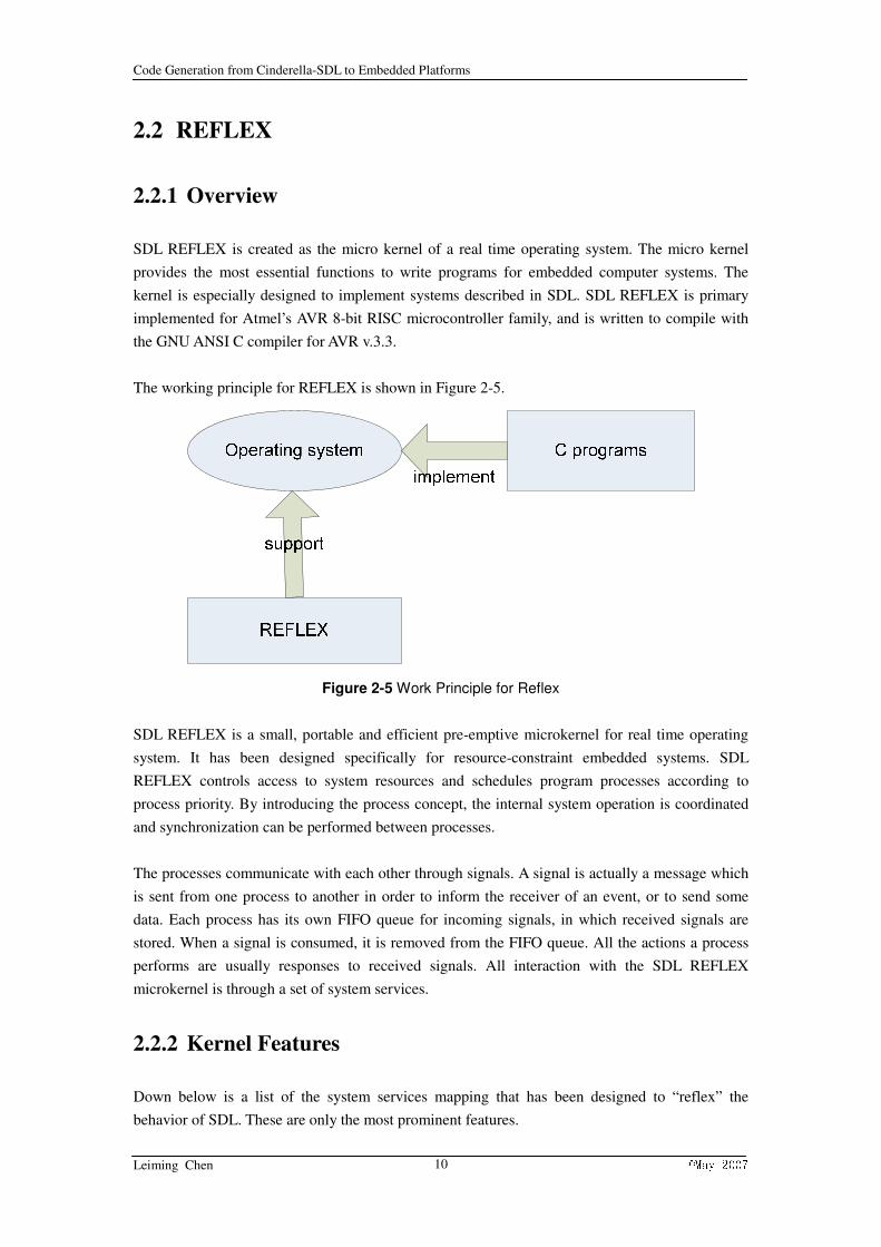
The working principle for REFLEX is shown in Figure 2-5.
Figure 2-5 Work Principle for Reflex
SDL REFLEX is a small, portable and efficient pre-emptive microkernel for real time operating
system. It has been designed specifically for resource-constraint embedded systems. SDL
REFLEX controls access to system resources and schedules program processes according to
process priority. By introducing the process concept, the internal system operation is coordinated
and synchronization can be performed between processes.
The processes communicate with each other through signals. A signal is actually a message which
is sent from one process to another in order to inform the receiver of an event, or to send some
data. Each process has its own FIFO queue for incoming signals, in which received signals are
stored. When a signal is consumed, it is removed from the FIFO queue. All the actions a process
performs are usually responses to received signals. All interaction with the SDL REFLEX
microkernel is through a set of system services.
2.2.2 Kernel Features
Down below is a list of the system services mapping that has been designed to “reflex” the
behavior of SDL. These are only the most prominent features.

Code Generation from Cinderella-SDL to Embedded Platforms
Leiming Chen ©May 2007 11
1. CREATE->CREATE(process_code,process_priority,process_stacksize)
2. INPUT->INPUT(signal1,signal2,…)
3. SIGNAL->SIGNAL(number-of-arguments, argument1,…)
4. OUTPUT->OUTPUT(signal,destination,argument1,…)
5. TIMER->NEW_TIMER()
6. SET->SET(duration,TIMER)
7. RESET->RESET(TIMER)
8. ACTIVE->ACTIVE(TIMER)
9. STOP->STOP()
10. SAVE->SAVE(signal1,signal2,…)
11. START->START()
12. PID->SELF(), SENDER(), PARENT() and OFFSPRING()
In addition to the previously mentioned functions which are described in SDL, there are more
functions in SDL REFLEX which isn’t described in SDL, but is critical to completely implement
the behavior of SDL.
1. WAIT_SIGNAL()
2. GET_SIGNAL_DATA(parameter1,…)
In this REFLEX supporting service, there are several SDL features are not supported, they are
listed below:
1. system structure
2. communication (channels, signal routes)
3. constructs (package, type, service, context parameters)
4. imported/exported
5. continuous signal
6. enabling condition
7. view
8. spontaneous signal
This system service is not complete and several places need to be modified. However, it supplies a
basis supporting libraries for codes generated from SDL diagrams.

Code Generation from Cinderella-SDL to Embedded Platforms
Leiming Chen ©May 2007 12
Chapter 3 Analysis of Some Existing Code
Generators
The auto code generation from models has been in use for several years. There are some
code-generators exist. However, most of them are commercial tools and they are not free. In this
chapter, a detailed analysis of these tools will be given. In order to have a systematic structure and
related subjects of these tools, the related areas which will be concerned are:
1. application area
2. supporting libraries
3. generated files
4. user setting
3.1 C-micro SDL to C compiler
C-micro SDL to C compiler is developed by Telelogic Tau for code generation. It can analyze SDL
systems and generate C programs from them. The generated code can be compiled on C-micro
RTOS, which is a library with a configurable SDL kernel. The C-micro Library and the SDL
Target Tester target library are not available as a pre-linked library but are delivered as source to
enable scaling of the kernel. The C-micro SDL to C compiler handles SDL concepts according to
the semantics of the SDL-92.
Application Area
The Telelogic Tau itself contains the drawing panel in which SDL diagram system can be drawn.
The C-micro SDL to C compiler extracts all the properties from the SDL diagram can transform it
into C.
The application areas for the C-micro SDL to C Compiler are: generation of applications,including embedded system applications with real time characteristics and generation of target
debug applications. The generated code combined with the C-micro library is highly optimized,
which is unavoidable for microcontrollers and real-time applications.
Supporting Libraries
The C-micro library consists of a configurable SDL kernel together with all the necessary SDL
data handling functions. The collection of C functions and C modules make up the so called SDL
machine.
The C files, which are generated by the C-micro SDL to C Compiler, can only be used in
connection with the C-micro Library and the SDL Target Tester. It is not possible to validate and
simulate the SDL system with the C code generated by C-micro as this code is only suitable for
Code Generation from Cinderella-SDL to Embedded Platforms
Leiming Chen ©May 2007 13
target applications.
Generated files
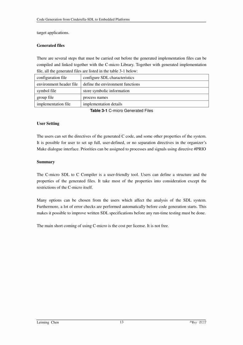
There are several steps that must be carried out before the generated implementation files can be
compiled and linked together with the C-micro Library. Together with generated implementation
file, all the generated files are listed in the table 3-1 below:
configuration file configure SDL characteristics
environment header file define the environment functions
symbol file store symbolic information
group file process names
implementation file implementation details
Table 3-1 C-micro Generated Files
User Setting
The users can set the directives of the generated C code, and some other properties of the system.
It is possible for user to set up full, user-defined, or no separation directives in the organizer’s
Make dialogue interface. Priorities can be assigned to processes and signals using directive #PRIO
Summary
The C-micro SDL to C Compiler is a user-friendly tool. Users can define a structure and the
properties of the generated files. It take most of the properties into consideration except the
restrictions of the C-micro itself.
Many options can be chosen from the users which affect the analysis of the SDL system.
Furthermore, a lot of error checks are performed automatically before code generation starts. This
makes it possible to improve written SDL specifications before any run-time testing must be done.
The main short coming of using C-micro is the cost per license. It is not free.
Code Generation from Cinderella-SDL to Embedded Platforms
Leiming Chen ©May 2007 14
3.2 C-advanced/ C-basic
The C-advanced/C-basic SDL to C Compiler is also developed by Telelogic Tau for code
generation. It can translate your SDL system into a C program that you can compile and link
together with a runtime library to form an executable program, such as a simulator, a validator or,
in the case of C-advanced, an application. The C-advanced/C-basic SDL to C Compiler handles
the majority of SDL concepts according to the definition of SDL-92.
Application Areas
The same as C-micro, C-advanced/C-basic can also read the SDL diagram from the drawing panel
and extract the elements to transform.
There are a number of application areas for C-advanced/C-basic SDL to C compiler: functional
simulation and debugging of protocol specifications, debugging of system designs described in
SDL, generation of applications, including embedded system applications with real time
characteristics, performance simulations and simulation of the behavior behind a user interface
prototype.
Supporting Libraries
Unlike C-micro library which has a complete SDL kernel for embedded platforms, the runtime
library for C-advanced/C-basic is used for normal C simulation. It is not so high optimized for
embedded systems.
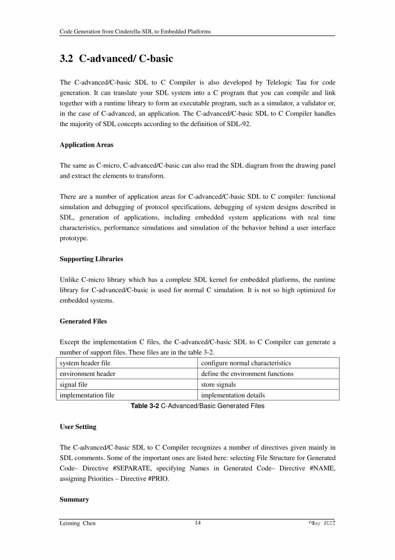
Generated Files
Except the implementation C files, the C-advanced/C-basic SDL to C Compiler can generate a
number of support files. These files are in the table 3-2.
system header file configure normal characteristics
environment header define the environment functions
signal file store signals
implementation file implementation details
Table 3-2 C-Advanced/Basic Generated Files
User Setting
The C-advanced/C-basic SDL to C Compiler recognizes a number of directives given mainly in
SDL comments. Some of the important ones are listed here: selecting File Structure for Generated
Code– Directive #SEPARATE, specifying Names in Generated Code– Directive #NAME,
assigning Priorities – Directive #PRIO.
Summary

Code Generation from Cinderella-SDL to Embedded Platforms
Leiming Chen ©May 2007 15
The C-advanced/C-basic SDL to C Compiler is also user-friendly and easy to use. Users can
define the structure of the generated code and some other properties as well. There are some other
features for them. The partitioning concept is a way to divide one SDL system into several
applications. As a special case this also means that it is possible to simulate and validate selected
parts of a system. The difference between partitioning and separation should be noted. The
partitioning feature is a way to select the parts of an SDL system which should be handled, while
the separation feature is a way to select the file structure for the generated files.
However, C-advanced/C-basic is not designed specially embedded platforms; the generated codes
can compile smoothly if connected with libraries. Since the resource consuming and stack size
which are of crucial importance to RTOS are not considered, it is not 100% suited for embedded
platforms. Another shortcoming is that it is not free as well.

Code Generation from Cinderella-SDL to Embedded Platforms
Leiming Chen ©May 2007 16
3.3 ConTraST
ConTraSt is a configurable C++ code generator that provides a mapping of SDL specification in
SDL/PR to an object oriented C++ representation. The transformation from one high level
language to another allows for the configuration of supported language features, giving it the
name “a configurable transpiler”. The intention is to obtain the object oriented structure and
thereby increase the readability and traceability of the generate code. This code is compiled
together with an SDL runtime environment, which was derived by manually transforming the
formal semantics of SDL-2000 into C++, preserving both structure and behavior. This provides
continuous traceability from the SDL specification to the executing system, including its runtime
environment.
Application Areas
ConTraSt takes SDL/PR file as the source file. It means any SDL specification file with text
format can be transformed using ConTraSt.
The application area for ConTraSt is mainly for simulation of the systems. To execute the
generated C++ files on real time embedded platform, some requirements need to be specified. For
example, the implementation language needs to be C++.
Supporting Libraries
High level languages have the same view of the object-oriented structure. Temporally, ConTrasT
does not have special supporting libraries to base.
Generated Files
Only C++ files are generated since the high level transformation posses the object-oriented
structure.
User Setting
Automatic code generation makes the whole code generation process does not require any user
special settings.
Summary
The feature in transformation is to exploit and retain the given object oriented structure of
SDL/PR, allowing for a successive traceability from an SDL specification to its C++
representation. This is achieved by the inheritance of C++ classes, each representing one specific
SDL-96 object. Most of these objects, such as plain data types or signals, can be described by
simple classes with parameters, while processes with corresponding types are represented by the
use of template classes. Therefore, a complete SDL system specification can be transformed into

Code Generation from Cinderella-SDL to Embedded Platforms
Leiming Chen ©May 2007 17
an object oriented C++ representation. A hierarchical composition of classes is used to implement
the visibility of definitions and variables, which also allows for the application of identifiers with
scope information.
As a C++ transpiler, ConTraST can simulate the SDL system with its runtime environment in an
efficient way. However, to execute the codes on real platforms need to require the platforms have
C++ library support. The ConTraSt is a free code generator.

Code Generation from Cinderella-SDL to Embedded Platforms
Leiming Chen ©May 2007 18
3.4 Cinderella SITE
Cinderella SITE is a code-generator that generates ANSI C++ from SDL. It is closely integrated
with the Cinderella SDL. Cinderella SITE supports most of SDL-96 plus selected parts of
SDL-2000, including exception handling. Code generation errors are reported in the Cinderella
SDL in the explorer view.
Application Areas
Different from the ConTrasT, Cinderella SDL can take both graphical and textual SDL
specification in Cinderella tool and transform it into target C++. The main application area is
simulation.
Supporting Libraries
High level languages have the same view of the object-oriented structure; it does not need special
supporting libraries to base.
Generated Files
Only C++ files are generated since the simulation does not need special support.
User Setting
Automatic code generation makes the whole code generation process does not require any user
special settings.
Summary
SITE also allows for the generation of code that produces MSC when executed. The MSC
generation feature is decorated with implementation that links back to the SDL model to facilitate
execution tracing.
The SITE code generator supports the environment models like: CORBA, COM and DLL
plug-ins.
However, like other C++ generators, to execute the codes on real platforms need to require the
platforms have C++ library support. SITE plug-in in Cinderella SDL is a commercial version; it
can transform graphical SDL system. There is also a free academic version which can transform
textual specified SDL system.

Code Generation from Cinderella-SDL to Embedded Platforms
Leiming Chen ©May 2007 19
3.5 Comparison among Existing Code Generators
After we have analyzed some existing code generators, a comparison among them is made. This is
shown in chart 3-1. We compared these tools from five aspects: portability (p), executable (e),
integrity (i), structure (s) and user-friendly (f).
0%
20%
40%
60%
80%
100%
p e i s f
C-micro
C-advanced/basic
ConTraSt
SITE
Chart 3-1 Existing Code Generators Comparison

Code Generation from Cinderella-SDL to Embedded Platforms
Leiming Chen ©May 2007 20
Chapter 4 Design Consideration
4.1 Motivation
SDL is a one of the most successful modeling language which helps designers express and verify
their design ideas in an adequate way. SDL adopted object-oriented method in implementing and
this can greatly improve the productivity, quality and reusability. Auto code generation from SDL
is one of the approaches to achieve these conveniences.
In the master topic 30 of 2004, a real time operating system for embedded platforms was built in C.
This operating system can provide SDL primitives, such that an easy transformation from SDL to
this operating system is possible. Until now, the students and teachers in HIA need to draw the
SDL system diagram and at the same time write same C code to implement on AVR platforms. It
doubles the workload for them, so the need for a C code generator is urgent and necessary.
There are already some C code generators exist, however, as we mentioned before, most of them
are commercial. At the same time, their generated codes can only work with their own supporting
libraries. So if we choose to use other code generators, the REFLEX can not work and the
payment for them is a bit heavy.
Now, the better option left is to develop a new and free SDL C code generator. It can take the
supporting library REFLEX into consideration and generate the corresponding C code. If this code
generator works, it can greatly ease the workload for students and teachers in HIA and reduce the
time between system design and implementation.
I have some research experience in model driven technology. This project of code generation just
belongs to this field. I have learned SDL last semester in the course formal methods. It seems SDL
is an easy and friendly tool. All the related knowledge I posses can support this project.
4.2 Decision Making
Cinderella SDL is a very useful and user-friendly SDL tool, it almost provides all the features
contained in SDL-92 semantics. Cinderella Company also has academic relationships with HIA;
the students can use Cinderella SDL free in courses. I have used Cinderella SDL last semester. So
I am familiar with it. Based on these, Cinderella SDL is chosen as the SDL system building
environment.
The Cinderella API is a feature which allows you to invoke external programs from Cinderella
SDL. This way, Cinderella SDL can be extended and customized to accommodate special needs.
Cinderella SDL itself provides a very useful plug-in folder for users who want to develop their
own function program. These plug-in files are written in C++, and compiled into DLL extension

Code Generation from Cinderella-SDL to Embedded Platforms
Leiming Chen ©May 2007 21
files. They can use internal Cinderella API functions to extract all the needed components out. It is
easier than reading in the SDL text specification and parses it directly. So I chose to use C++ to
program and compile the program into DLL extension file as plug-in.
After we have made all the things clear, we made a workflow table 4-1 for future work.
Stage 1: Study Cinderella API and the examples
Stage 2: Practice to extract all elements needed
Stage 3: Adopt the structure in extraction
Stage 4: Compile the generated codes
Stage 5: Test code on AvR micro controller
Table 4-1 Workflow
4.3 Elements Classification and Analysis
In SDL, the elements are classified as architecture, behavior, communication and data four
sections. However, in element transformation, this classification is proper. In order to give a clear
and systematic structure of the SDL elements, we try to categorize all the basic and important
elements into three main types:
1. Structural element. These kinds of elements have their own scope diagrams.
2. Definition element. Elements specified in text symbol.
3. Behavior element. Elements specified in behavior description area.
The structural element consists of system, block, process and procedure diagram elements. In
definition element field, signal definition, data definition and variable declaration will be found.
Behavior elements are used to specify the behaviors of process. It contains symbols which
composite the behaviors of the process. They are classified as: start, state-trigger and free action.
There are still some detailed categorizations left. We will shoe the whole element structure in
Figure 4-1.

Code Generation from Cinderella-SDL to Embedded Platforms
Leiming Chen ©May 2007 22
Figure 4-1 SDL Element Structure
In order to simplify the difficulty of the projects, some of the features are not taken into
consideration, they are listed below:
1. Constructs. They are not so critical in building a system especially for embedded platform.
2. Imported and exported features. In target C program, to posses variables in different
functions is a bit tricky to implement.
3. Continuous signal and enable condition. Not critical in describing systems.
We keep other elements and transform them with proper treatments. The element mapping from
source SDL attributes to target C code will be introduced in next chapter.

Code Generation from Cinderella-SDL to Embedded Platforms
Leiming Chen ©May 2007 23
Chapter 5 Transformation Description
5.1 Introduction
To transform source SDL diagram into target C code, a detailed mapping from SDL diagram
contained features to C functional codes need to be specified. In this chapter, a detailed description
of transformations will be supplied.
Every element which has been analyzed and considered to be taken is transformed with a detailed
description including where it is used and which form it should be like in target C.
5.2 Element Mapping
According to the element analysis from last chapter, all the units in a SDL diagram can be divided
into three main categories: structural element, definition element and behavior element. Except the
normal categories, there is a very common type used in SDL. It is “expression”. The expression is
used almost in all the elements existing in the SDL, so it is separated as an important part and will
be given its own transformation section.
The mapping of each element will be given one by one following these categories. The source
syntax diagram with necessary explanations comes first, then transformed target C code format
with the properties specified in syntax diagram
In the transformation specification, some of the symbols may be used for structuring the flexibility
and simplicity. They are listed in the table 5-1:
“::” the function of the element
“<>” name of the element
“{}” hold keywords
“*” number of the elements is 0 or more
“+” number of the elements is 1 or more
“->” properties belong to element
Table 5-1Transformation symbols
5.3 Structural Elements Transformation
In this section, all the structural elements will be introduced according to the range size which
they can in charge of. The sequence is: system, block, process and procedure.

Code Generation from Cinderella-SDL to Embedded Platforms
Leiming Chen ©May 2007 24
5.3.1 System
The syntax diagram of the system is shown in Figure 5-1.
Figure 5-1 System Syntax Diagram
The system contains a system-heading defining <system-name>. The system also may contain
textual definitions in the def-elem which stands for definition elements. The def-elem will be
introduced in definition element section. The block-elem stands for block element which will be
introduced later.
The name of the system is <system-name>, so the generated files are <system-name>.c and
<system-name>.h. The <system-name>.c file should contain some basic information such as
header files and basic type definitions.
/ system-name.c /
#include <stdlib.h>
#include <sdl_io.h>
#include <string.h>
#include “<system-name>.h”
typedef unsigned int natural;
typedef bool boolean;
typedef unsigned int integer;
typedef unsigned char character;
typedef string charstring;
typedef float duration;
typedef float time;
typedef float real;
def-elem::dcl;
block-elem::dcl;
block-elem::iden_process;
SIGNAL def-elem::.signal_dcl;
block-elem::signal_dcl;
block-elem::ini_process;
int main(void)
{
def-elem::signal_ini;

Code Generation from Cinderella-SDL to Embedded Platforms
Leiming Chen ©May 2007 25
block-elem::crt_process;
START();
return 0;
}
block-elem::trans;
/ <system-name>.h /
#ifndef system-name_h
#def system-name_h
block-elem::set_process_pri;
block-elem.process-elem::set_process_size;
#define timer_standard 100;
5.3.2 Block
The block-elem has the referenced syntax diagram of Figure 5-2.
Figure 5-2 Block Syntax Diagram
The structure of the block-elem is almost the same as system. The block-elem contains a
block-heading defining the block-name. The block-elem also may contain textual definitions in the
def-elem. A process-elem defines process elements in a block-elem. There may be procedure-elem
exist as well. They belong to procedure elements.
The block in target code does not have practical effect. However, it will give boundary signs such
as “******” to inform program readers where codes come to. There are a list of block element
functions will be transformed.
dcl:
def-elem::dcl;
iden_process:
process-elem::iden;
signal_dcl:
def-elem::signal_dcl;
init_process:

Code Generation from Cinderella-SDL to Embedded Platforms
Leiming Chen ©May 2007 26
process-elem::ini;
crt_process:
process-elem::crt;
set_process_pri:
process-elem::set_pri;
set_process_size
process-elem::set_size;
trans:
//****************************<block-name> start*********************************
procedure-elem:implen;
process-elem::implen;
//****************************<block-name> end**********************************
5.3.3 Process
The syntax diagram of process-elem is shown in Figure 5-3.
Figure 5-3 Process Syntax Diagram
A process-heading defines the <process-name>. The process-elem also may contain textual
definitions in the def-elem. In process scope, the behavior-des-elem stands for behavior elements
which will be introduced in behavior element. A process-graph-area defines the behavior of a
process in a process-elem. The procedure-elem may exist in this scope.
The process scope may contain procedure element, so the generated code will show as a range
with the same signs of block element. The process element itself will be transformed to a C
function without return values. There is also a list of functions in process element.
iden:
PID <process-name>;
ini:
void <process-name>_code(void);

Code Generation from Cinderella-SDL to Embedded Platforms
Leiming Chen ©May 2007 27
crt:
<process-name>=CREATE(<process-name>_code,<process-name>-pri,
<process-name>-stacksize);
implen:
//****************************<process-name> start********************************
procedure-elem::ini;
void <process-name>(){
def-elem::var_dcl;
def-elem:: dcl;
behavior-des-elem::enum_state;
behavior-des-elem::temp_sig;
behavior-des-elem::start;
behavior-des-elem::switch_state;
}
procedure-elem:implen;
//****************************<process-name> end********************************
set-pri:
#define <process-name>-pri 5;
set-size:
#define <process-name>-stacksize 100;
5.3.4 Procedure
The syntax diagram for procedure-elem is shown in Figure 5-4
Figure 5-4 Procedure Syntax Diagram
A procedure-heading defines the <procedure-name> and procedure-parameters. The
procedure-elem also may contain textual definitions in the def-elem. A procedure-graph-area
defines the behavior of a procedure in a behavior-des-elem.
Unlike process element, procedure element can have return value in its transformed C function.
The syntax diagram of procedure-parameters is shown in Figure 5-5.

Code Generation from Cinderella-SDL to Embedded Platforms
Leiming Chen ©May 2007 28
Figure 5-5 Procedure Parameter Syntax Diagram
ini:
procedure-parameter->return-data-type procedure-name (procedure-paramters->
procedure-parameter1,procedure-parameter2,….);
implen:
//****************************<procedure-name> start******************************
procedure-parameters::return procedure-name(procedure-paramters::pars);
{
def-elem::dcl;
behavior-des-elem::start;
}
//****************************<procedure-name> end******************************
5.4 Definition Elements Transformation
The text symbol contains def-elem local to the scope it belongs to. It has three categorizes: signal
definition, data definition and variable declaration.
5.4.1 Signal Definition
The syntax diagram for signal-definition in the def-elem is shown in Figure 5-6
Figure 5-6 Signal Syntax Diagram
signal_dcl:
SIGNAL <signal-name>;
signal_ini:
SIGNAL NEW_SIGNAL(signal-parameter1,signal-parameter2,…);
5.4.2 Data Definition
In the data-definition, three data types are concerned: syntype-definition, synonym-definition and
datatype-definition (only for array). The functions supplied here belong to def-elem::dcl.
Code Generation from Cinderella-SDL to Embedded Platforms
Leiming Chen ©May 2007 29
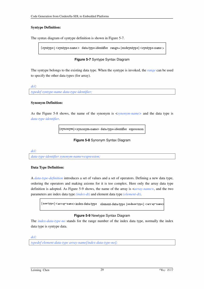
Syntype Definition:
The syntax diagram of syntype definition is shown in Figure 5-7.
Figure 5-7 Syntype Syntax Diagram
The syntype belongs to the existing data type. When the syntype is invoked, the range can be used
to specify the other data types (for array).
dcl:
typedef syntype-name data-type-identifier;
Synonym Definition:
As the Figure 5-8 shows, the name of the synonym is <synonym-name> and the data type is
data-type-identifier.
Figure 5-8 Synonym Syntax Diagram
dcl:
data-type-identifier synonym-name=expression;
Data Type Definition:
A data-type-definition introduces a set of values and a set of operators. Defining a new data type,
ordering the operators and making axioms for it is too complex. Here only the array data type
definition is adopted. As Figure 5-9 shows, the name of the array is <array-name>, and the two
parameters are index data type (index-dt) and element data type (element-dt).
Figure 5-9 Newtype Syntax Diagram
The index-data-type-no stands for the range number of the index data type, normally the index
data type is syntype data.
dcl:
typedef element-data-type array-name[index-data-type-no];
Code Generation from Cinderella-SDL to Embedded Platforms
Leiming Chen ©May 2007 30
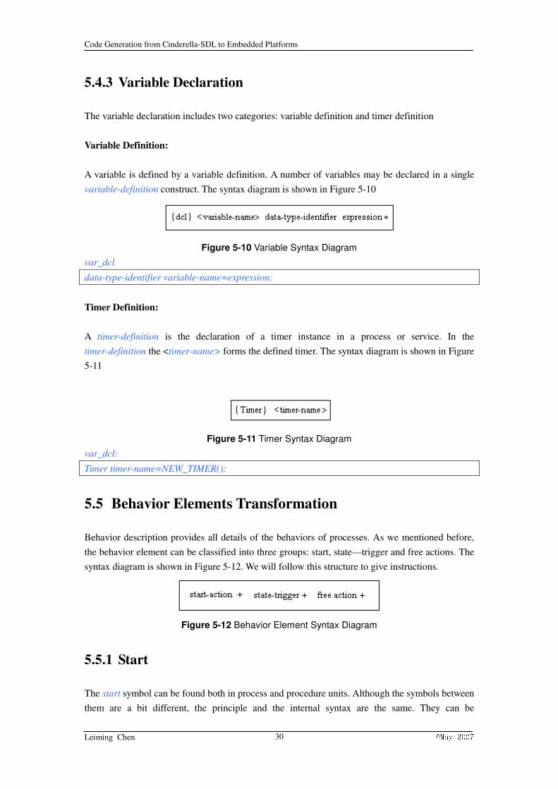
5.4.3 Variable Declaration
The variable declaration includes two categories: variable definition and timer definition
Variable Definition:
A variable is defined by a variable definition. A number of variables may be declared in a single
variable-definition construct. The syntax diagram is shown in Figure 5-10
Figure 5-10 Variable Syntax Diagram
var_dcl
data-type-identifier variable-name=expression;
Timer Definition:
A timer-definition is the declaration of a timer instance in a process or service. In the
timer-definition the <timer-name> forms the defined timer. The syntax diagram is shown in Figure
5-11
Figure 5-11 Timer Syntax Diagram
var_dcl:
Timer timer-name=NEW_TIMER();
5.5 Behavior Elements Transformation
Behavior description provides all details of the behaviors of processes. As we mentioned before,
the behavior element can be classified into three groups: start, state—trigger and free actions. The
syntax diagram is shown in Figure 5-12. We will follow this structure to give instructions.
Figure 5-12 Behavior Element Syntax Diagram
5.5.1 Start
The start symbol can be found both in process and procedure units. Although the symbols between
them are a bit different, the principle and the internal syntax are the same. They can be

Code Generation from Cinderella-SDL to Embedded Platforms
Leiming Chen ©May 2007 31
transformed equally.
The syntax diagram for start is in Figure 5-13.
Figure 5-13 Start Syntax Diagram
The start symbol itself is transformed to nothing. However in the process initiation, the start
symbol will trigger other transitions until it comes to a state or a stop symbol.
start:
transition::trans;
5.5.2 State
Although the state symbols in process and procedures are the same, the way to treat them is
different. So they need to be classified into two sections.
Process state:
The syntax diagram of state symbol is shown in Figure 5-14 and the external syntax diagram is
shown in Figure 5-15.
Figure 5-14 State Syntax Diagram
Figure 5-15 External State Syntax Diagram
The process states have several places to be set. First, all the distinguishing states in a process
should be enumerated before the behavior-des-elem starts and set a temporary state for later use.
enum_state;
Enum{ state-name1,state-name2,…}
current-state=state-name1;
When the process transitions come to a state symbol, according to the switch structure based on all
the states in the process, the direction will be a case fork combined with the state-name:
switch_state:
switch(current-state)
{
case state-name1:trigger::trans;
break;
case state-name2:trigger::trans;
break;

Code Generation from Cinderella-SDL to Embedded Platforms
Leiming Chen ©May 2007 32
…………..
Default: break;
}
Procedure Sate:
The state symbol in procedures has the same syntax diagram used in process. However, the state
symbol itself will not be transformed into target code. The state symbol will be used to trigger
next transitions.
state:
trigger::trans;
5.5.3 Trigger
There are several kinds of trigger symbols. In this project, input and save will be considered and
taken. The functions supplied here all belong to trigger::trans;
Input:
It is different in SDL and target C code. In target, except input symbol, additional functions need
to be specified in target codes. They are signal-waiting function and signal-parameters-getting
function. All these functions work together can do the same function in RTOS as in SDL.
The syntax diagram for input is in Figure 5-16
Figure 5-16 Input Syntax Diagram
The external syntax for input and transitions after input is shown in Figure 5-17 and Figure 5-18.
Figure 5-17 External Syntax Diagram1
Figure 5-18 External Syntax Diagram2
Before the process begins, create a temporary signal variable to use for storing signal receiving.
temp_sig:
SIGNAL receive;
trans:
INPUT(signal-identifier1, signal-identifier2,…,endlist);
receive=WAIT_SIGNAL();

Code Generation from Cinderella-SDL to Embedded Platforms
Leiming Chen ©May 2007 33
GET_SIGNAL_DATE(&variable1,&variable2,…);
if(receive== signal-identifier1){transition::trans}
else if (receive== signal-identifier2){transition::trans}
….
else{transition::trans}
If the situation happens in procedure, the result is like:
trans:
INPUT(signal-identifier1, signal-identifier2,…,endlist);
WAIT_SIGNAL();
GET_SIGNAL_DATE(&variable1,&variable2,…);
transition::trans;
Save:
The save symbol is another trigger, the syntax diagram of save is shown in Figure 5-19 and the
external relation diagram is shown in Figure 5-20
Figure 5-19 Save Syntax Diagram
Figure 5-20 External Save Syntax Diagram
trans:
SAVE(signal-identifier1,signal-identifier2,…,endlist); / SAVE(none);
5.5.4 Free Actions
The free actions can be separated into two types: action and transition end. The output, set/reset,
task, procedure call and create belongs to action. The decision, join and connection, next-state,
return and stop belong to transition end. All the functions here belong to transition::trans.
5.5.4.1 Action
Output:
The syntax of the output is shown in Figure 5-21.
Figure 5-21 Output Syntax Diagram

Code Generation from Cinderella-SDL to Embedded Platforms
Leiming Chen ©May 2007 34
The output in target codes needs to specify the destination process. The destination has the format
of the destination Pid, so it is specified as destination.
trans:
OUTPUT(signal-identifier, destination, &variable1,&variable2,…);
Task:
The task has two formats shown in Figure 5-22 and Figure 5-23
Figure 5-22 Task Syntax Diagram1
Figure 5-23 Task Syntax Diagram2
trans:
variable=expression;/ informal-text,…
Set/Reset
The set has the format in Figure 5-24
Figure 5-24 Set Syntax Diagram
The reset has the format in Figure 5-25
Figure 5-25 Reset Syntax Diagram
trans:
SET(expression*timer-standard,timer-identifier);/ RESET(,timer-identifier);
Procedure call:
The call specifies the name of the procedure and the parameters. In Figure 5-26
Figure 5-26 Procedure Call Syntax Diagram
trans:
procedure-name(procedure-parameter1, procedure-parameter2,…)
Create:

Code Generation from Cinderella-SDL to Embedded Platforms
Leiming Chen ©May 2007 35
The process instance is created in the same block as the process in which the create-request is
interpreted.The syntax diagram is shown in Figure 5-27
Figure 5-27 Create Syntax Diagram
trans:
CREATE(process-identifier,process-identifier_pri,process-identifier_size);
5.5.4.2 Transition End
Decision:
The external syntax diagram of decision is shown in Figure 5-28
Figure 5-28 Decision Syntax Diagram
The syntax diagram of decision is shown in Figure 5-29.
Figure 5-29 Decision Question Syntax Diagram
The answer is shown in Figure 5-30
Figure 5-30 Decision Answer Syntax Diagram
Assume all the options have the range.
trans:
if((expression1==range1)==true){transition::trans}
else if((expression2==range2)==true){transition::trans}
……….
else{transition::trans}
Join and Connection:
The syntax diagram is shown in Figure 5-31
Figure 5-31 Label Syntax Diagram
There are two types: out-connector and in-connector. Their symbols are shown in Figure 5-32 and
Figure 5-33.

Code Generation from Cinderella-SDL to Embedded Platforms
Leiming Chen ©May 2007 36
Figure 5-32 Join Syntax Diagram
Figure 5-33 Connector Syntax Diagram
trans:
goto label-name;/ label-name: transition::trans;
Stop:
The syntax diagram of stop symbol is shown in Figure 5-34
Figure 5-34 Stop Syntax Diagram
trans:
transition::trans;
STOP();
Return:
The syntax diagram is shown in Figure 5-35
Figure 5-35 Return Syntax Diagram
trans:
expression::expr;
5.6 Expression
The expressions which have been taken into account are infix-expression, parenthesis-expression,
operator-application, imperative-application and conditional-expression. They will be introduced
separately.
Infix-expression:
The syntactic form used is the infix form, as shown in Figure 5-36
Figure 5-36 Infix-expression Syntax Diagram
expr:

Code Generation from Cinderella-SDL to Embedded Platforms
Leiming Chen ©May 2007 37
expression dynamic-operator expression;/monadic-operator expression;
Parenthesis-expression:
The syntax diagram is in Figure 5-37
Figure 5-37 Parenthesis-expression Syntax Diagram
expr:
(expression)
Operator-application:
The syntax diagram is in Figure 5-38
Figure 5-38 Operator-application Syntax Diagram
The format depends on kind of the operator-identifier belongs to. The operators need to be
changed are: “or”, “and” and “//”. They will be changed to “||”, “&&” and “strcat”.
expr:
expression operator-identifier expression;/strcat(expression1.expression2);
Imperative-operator:
The situations considered in imperative-operator is shown in Figure 5-39
Figure 5-39 Imperative-operator Syntax Diagram
expr:
Pid SELF()/SENDER()/PARENT()/OFFSPRING()
bool ACTIVE(TIMER timer-name);
procedure-name(procedure-parameter1, procedure-parameter2,…);
Conditional-expression:
The syntax diagram is in Figure 5-40.
Figure 5-40 Conditional-expression Syntax Diagram
expr:

Code Generation from Cinderella-SDL to Embedded Platforms
Leiming Chen ©May 2007 38
if(expression1){exprssion2}else{expression3}
Code Generation from Cinderella-SDL to Embedded Platforms
Leiming Chen ©May 2007 39
Chapter 6 Transformation Technique
The last chapter gives a detailed element mapping from source SDL diagram properties to target C
code. In this chapter, we will illustrate how to make the transformation work. In this introduction,
the structure in analyzing elements will be kept.
6.1 General
This project takes Cinderella SDL as running environment, so the API of Cinderella SDL is
invoked. The Cinderella API is a feature which allows you to invoke external programs from
Cinderella SDL. This way, Cinderella SDL can be extended and customized to accommodate
special needs. Typical such add-ons can be:
1. Various kinds of post-analysis tools which checks that certain company specific or
methodology specific rules are obeyed.
2. Filters which flattens the SDL specification some way, for example in order to overcome
limitations imposed by other tools.
3. Code generators.
There is a very simple way to invoke the API. It is to build a SDL plug-in which is written in C++
and further to be compiled to a DLL file. Cinderella SDL can invoke this plug-in, and adopt the
functions to obtain elements from the SDL based diagram.
6.2 Overview of the API
The Capi is the topmost class representing the API. It consists of two parts: The internal
representation of the concrete syntax and the derived properties for the entities in the internal
representation. Syntaxtree is the internal representation of the SDL specification. Propertiestree
is the information derived from the internal representation. Propertiestree should be regarded as a
representation of the SDL entities on a normalized convenient form. In order to take a SDL
diagram into parsing, the corresponding API tree of the diagram needs to be initialized.
The Syntaxtree contains the internal representing derived from the concrete syntax. Together with
Propertiestree, the Syntaxtree constitutes the contents of API tree which is the root class
defining the whole API. Inside Syntaxtree, spellmap is the list of spellnumbers assigned to the
names of the specification. This can be used to extract elements using their spellnumbers.
The Propertiestree contains the properties which are derived from Syntaxtree during analysis.
Together with Syntaxtree, the Propertiestree constitute the contents of API tree which is the root
class defining the whole API. The most important part of Propertiestree is the dictionaries of the
entities defined in the SDL specification. There is one dictionary for each Qaulifierelementkind.
Each dictionary consists of a list of Quals, each representing an entity of the given
Qaulifierelementkind. A Qual contains information about all relevant information for an entity.

Code Generation from Cinderella-SDL to Embedded Platforms
Leiming Chen ©May 2007 40
The Propertiestree has two important functions. The selectqualdict() return the first Qual in the
dictionary indicated by the Qaulifierelementkind parameter. To traverse the whole dictionary,
apply Qual::next() until NULL is reached or use traversedict(). The traversedict
(Qaulifierelementkind ,int (*func)(Qual*) ) applies the function func on each Qual contained in
the dictionary indicated by the Qaulifierelementkind. If the function returns FALSE, the traversal
will stop.
There are some crucial attributes in the API tree; they are Qual, Diagram and Symbol.
Any SDL entity that can be defined in an SDL specification has a Qual associated. A Qual consist
of a number of fields which are common to all entities such as name and defining scope unit. It
also contains a part which is specific to the entity kind. For example, the entities which can have a
behavior graph associated (operators, processes, process types, procedures, services and service
types) have a GraphD in the Qual which contains information about states and transitions.
The Diagram class represents the diagram. No distinction is made between a diagram and a
diagram page. Those terms both refer to an object of class Diagram. A Diagram retains
information about e.g. the kind of diagram, the heading symbols of the diagram, the contained
symbols, the semantic descriptor (Qual) for the scope unit and the corresponding reference symbol
for the diagram. Even though every diagram page of a scopeunit has the same heading according
to SDL, separate heading symbols exist for each diagram page. This is in order to allow scaling
and positioning of the symbols in individual pages. The function traversesymbols(int
(*func)(Symbol *),int allpages,int skipheading=TRUE) traverse all symbols of the diagram. For
each symbol, the argument function func is called. If func returns FALSE, the traversal will stop
and traversesymbols() returns. If the argument allpages is TRUE, all pages of the diagram will be
traversed. If skipheading is TRUE, traversesymbols will skip the heading symbols of page(s).
Symbol represents an SDL symbol. The function uniqueid() is the unique identity of the symbol
within the (linked) file or specification in which it occurs. The identity is persistent to save and
open. The traverseoutgoing(int (*func)(Symbol *,Symbol *)) traverse all symbols having the
symbol as originating endpoint. For each symbol, the function func is called with the symbol as
parameter. The traverseincoming(int (*func)(Symbol *)) traverse all symbols having the symbol
as destination endpoint. For each symbol, the function func is called with the symbol as parameter.
The Symbol has some class members which can be used to specify for a particular symbol.
6.3 Element Extraction
The order for element extraction is: structural element extraction, definition element extraction,
behavior element extraction and expression extraction.
Structural Element Extraction:
The function selectdictqual(elemtkind) invoked. By setting the elementkind, the properties for this
kind of structural element can be extracted one by one. To extract the scope units system, block,
Code Generation from Cinderella-SDL to Embedded Platforms
Leiming Chen ©May 2007 41
process and procedure, the elementkind needs to be set to SYSTEMQUAL, BLOCKQUAL,
PROCESSQUAL and PROCEDUREQUAL. Every time invoking the function, one Qual is
extracted out. The next() function is used to select the next one.
In the transformation, the belonging relationships of different scopes need to be checked. The
function sur() will be used to check if the scope element belongs to another element.
Definition Element Extraction
The elements contained in definition element are: signal, data type and variable. They need
separate ways to be selected.
The signal definition can be extracted from the properties tree directly because the elementkind
can be set to SIGNALQUAL. So a Quallist of signals in the diagram is selected. We just need
next() function to access them one by one. The data type definition can be declared with scopes in
any level. The elementkind can also be set to SORTQUAL. A sortlist will be extracted from the
syntax tree. However, in this project, we prefer to extract the data type definition element in scope
unit.
The text symbol for each scope unit needs to be parsed, the definitionlist() function will return a
definition element list. The data type definition and variable declaration can be extracted from the
definition element list. The alt_syntypedef(), alt_newtypedef(), alt_synonymdef(), alt_vardef(),
alt_timerdef() and alt_prsymbol() are used to extract different definition elements. The next()
will also be invoked to select the next definition element.
Behavior Element Extraction
Behavior elements are represented as symbols. Every behavior element kind has a corresponding
symbol kind. The function kind() can be used to switch the parsed symbol kind. This will let
every element kind receive proper treatment.
All behavior elements belong to process or procedure Quals. To traverse the behavior symbols
with the same properties in a scope unit, the function traversesymbols(symbolfunc,1,1) is used.
But this function need diagram of the Qual, the function q_diagram() is called to exchange the
Qual element to Diagram.
The function traverseoutgoing() is used to check the next symbol this symbol reaches. This
function is called by symbols. If a certain symbol is found, for example, start or state symbols,
then this function can be used to check the next symbol. The nesting will be used to check the
symbols automatically one by one until it comes to a certain situation.
There are many kinds of behavior element symbols: start, state-trigger and free action. Every kind
has their own way to select the basic attributes. The state symbol has a state name list to be
accessed, the statenamelist() returns the list of state names that is specified in the state symbol. If

Code Generation from Cinderella-SDL to Embedded Platforms
Leiming Chen ©May 2007 42
starred() is TRUE, the list of names are those specified in parenthesis after the asterisk character.
The inputvarlist() returns the list of signals specified in the input. The signallist() returns the list
of signals specified in the save symbol. In output symbol, the outputsiglist() returns the list of
signals specified to be sent in the output symbol. Another function reachable() also needs to be
invoked to check the destination of the signal. The question() returns the expression which is
specified inside the decision symbol.
Expression Extraction
Expressions also have several kinds, the same as symbols, every kind has its own functions can be
invoked to check the wanted attributes. First, the alt_kind() function is used to move the
expression to the right type. Then different functions can be called directly. For example, in
infix-expression, three functions lexpr(),infixop() and rexpr() will separately get the expressions
and operators. The most basic and useful function is based on Id class. The class Id represents the
information that is associated to an identifier. It consists all the information in the indivisible
component, especially for name() function to get name of the component.
6.4 Principle
Then the techniques used in the transformation belong to model-driven techniques. It parses the
attributes of the SDL diagram represented system and takes them by building the syntax tree of the
system. The work principle can be shown in Figure 6-1.
Figure 6-1 Work Principle for SDL API

Code Generation from Cinderella-SDL to Embedded Platforms
Leiming Chen ©May 2007 43
Chapter 7 System Test
7.1 Results of Different Stages
To obtain the correctness of the different steps in this project, we try to divide the time into several
periods and verify the results achieved at that time.
Component extractions:
This is the first stage. After the analysis of the elements of the SDL system, necessary components
are classified and marked with highest priorities. The structural element, definition element and
behavior element are tested one by one.
The system, block, process and procedure can be extracted with full properties it possesses. The
name, contained unit, unit belongs to and parameters are extracted 100% correct.
The definition elements taken into account are signal definition, data type definition and variable
declaration. Signals can be selected easily with full properties. Data type define three basic new
data types, they have limitations in showing presenting some properties in target C code. The
variable declaration enjoys the full interpretation as signals. In this section, separate extraction can
be achieved 100%. However, predictable risk of property failing exist.
Almost all the behavior element symbols can be extracted with rather exact precision. Two kinds
of symbols have problem. The destination of the output signal and relationship between decision
question and option answer are still under construction. The completeness is 90%.
Structural extractions:
After we know how to extract information from a single unit, the connection among them and the
reassembling the structure in target code are the trickiest things.
Within structural elements, their relationships of belonging are things we need to check. The range
size they in charge of have been tested with full correctness.
The definition elements are not fully distributed according to the scope unit. However, the
interpretation among them has no difficulty. It is correct 100%.
Coming to behavior elements, using outgoing() functions can supply the passed symbols. There
are some problems unsolved in this stage. Join and connector have not been taken into consider.
Decision loops are the tricky part to be extracted in right manner. It will effect the format of
generated code. 90% of this stage has been completed.

Code Generation from Cinderella-SDL to Embedded Platforms
Leiming Chen ©May 2007 44
Tool test:
After the plug-in has been generated, it is put into Cinderella plug-in folder. The name is given
CGFR. It can generate target file every time it is invoked. The working promise is 100%.
Compile test:
When the codes are generated, they are compiled under WinAvR C compiler. At first, none of the
generated files can be compiled. After changing of some attributes, all the generated files can be
compiled without errors. The plug-ins have grown into 2. One is CGFR, one generates header file
with name config. The correctness is 100%.
Implementation test:
REFLEX has some problem in solving the input signals due to the confusion of different version
control. Many examples can not be executed on AvR chip with REFLEX based functions. In order
to have the verification of the result, we redesigned a small and simple supporting header function
and use the AvR self brought circuit-switch input signals to take place of input signals. By doing
so, we are completely successful in implementing the generated code of an example “tanker”. The
result of the generated code has the same effect as the manually written one. However, due to the
time constraints, we have not implemented other generated codes. The stage can only count 60%.
Based on the tests we have, a line chart 7-1 is made to show the process of the test.
00.20.40.60.811.2
Feb March April Maycompling errorimplementationerror
Chart 7-1 Process trend
7.2 Test Example
The example “tank” is tested and it is fully operational. So we will give a brief introduction to this
example and the compare manually written codes and generated codes. Full code generation and
manually comparison are also provided in appendix B.

Code Generation from Cinderella-SDL to Embedded Platforms
Leiming Chen ©May 2007 45
The tank is auto water warmer. It can sense empty, full and temperature automatically, then it will
adopt corresponding actions. If the tank is empty, water will be injected. If the tank senses full,
water will be stopped and warmer starts to work. If the temperature comes to a certain grade, it
will stop heating and sleep until water cooled or empty.
Compare chart 7-2 between codes generated (gc) and manually written codes (mc) from three
aspects number of the files (nof), simplicity (s) and comparability (c).
00.511.52nof s c gcmc
Chart 7-2 Comparison between Generated and Manually Written Codes

Code Generation from Cinderella-SDL to Embedded Platforms
Leiming Chen ©May 2007 46
Chapter 8 Discussion
8.1 Major Findings
Before all the work start, we made a systematic analyze of some existing code generators. By
catching the most attractive points in these generators, we get to know most of the significant
features a code generator needs to take care.
Then we changed our focus on REFLEX. The REFLEX supports some of the SDL notations
which can be transformed from SDL directly. We tried to find these functions and list them for
further usage.
When comes to the real transformation, we try to gather all the elements and classify them into
several groups. Some of them are essential in describing a system; they are kept and transformed
with full interpretation. In opposite, some of them which are not so critical are omitted in order to
simplify the project.
Finally, we developed a new code generator which can generate C codes from SDL system
diagram specification. The codes can be implemented on AvR micro-chip with the support from
the micro-kernel REFLEX. The name of the generator is given as CGFR. We also designed
another plug-in (Config) which generates the supporting header files for implementation code.
Users of CGFR can change the user defined the property values in the header file. The two
plug-ins can be put under Cinderella SDL and integrated with it. The C++ source code of the code
generators and plug-in DLL files can be found on cvs http://kildekode.hia.no/ in the CGFR folder.
8.2 Comparison with Existing C Code Generators
Due to the complexity and time constraints, the details of SDL elements are not fully expanded.
The whole system is transformed into one single C implementation file with a user defining
header file, this is not as good as other C generators since they all have their own generating
structure for users to choose. And there are several elements in transformation are not considered.
Only the kernel properties are chosen to be transformed.
Here, we will make a comparison between CGFR and existing C generators. The detail
information is shown in the chart 8-1. The aspects taken into consideration are: integrity (i),
simplicity (s), structure (t) and user-friendly (f).

Code Generation from Cinderella-SDL to Embedded Platforms
Leiming Chen ©May 2007 47
0%20%40%60%80%100%i s t f
C-microC-AdvancedCGFR
Chart 8-1 Comparisons between CGFR and Existing Code Generators
8.3 Comparison with Manually Written Target Code
The generated target code can be compiled well. It shows that the generated code is correct in
logic and semantics. However, compared to manually written code, it is a bit different.
First is the simplicity. Because this tool will transform all the elements and structure within the
regulations, so even sometime the code can be simplified, it would not do such a thing.
Second is the flexibility. It is easy and flexible to define variables and some informal texts in SDL,
and this can be well transformed manually, because system designers know how it comes. But to
fit for the transformation, some additional constraints need to be set, like designers need to specify
all the variants in text area and etc.
However, in general, the similarity of the generated code is very high except for some defined
structure as we mentioned in simplicity features.
8.4 Alternatives
Although we think that the method we used is the most direct and shortest way, there are some
other ways to generate code from SDL specifications. Here, we list them as alternatives for further
discussion.
The first method we want mention is parsing the PR SDL specification and generate target C code
from that. Because PR SDL specification has unique format for one system even their GR form is
a bit different, it can expand the usage range. Independent tool is needed because the source file
has no running environment to be based on.
The other way is to use other existing code generators which are under construction of special
development groups. These tools are very complete and mature. They handle many aspects and
the codes generated have been tested and verified for many times. However, they are commercial
version.

Code Generation from Cinderella-SDL to Embedded Platforms
Leiming Chen ©May 2007 48
A comparison chart 8-2 clearly shows their advantage and disadvantages in three aspects: cost
advantage (ca), functionality advantage (fa) and portability advantage (pa).
0%20%40%60%80%100%ca fa pa
CGFRPR GeneratorExsting Generator
Chart 8-2 Comparisons among Alternatives

Code Generation from Cinderella-SDL to Embedded Platforms
Leiming Chen ©May 2007 49
Chapter 9 Conclusion and Future Work
9.1 Conclusion
In this thesis, we discussed and developed a new C code generator CGFR. The micro kernel
REFLEX will provide the SDL notations support to implement the codes under the real time
operating system for AvR micro-chip. Based on the model-driven technology which can enhance
the software building, we proposed and developed several possible solutions to build the code
generator.
We began our research from analyzing some existing code generators such as C-micro,
C-Advanced/Basic, ConTraSt and Cinderella SITE. It is very important for us to study the
methods and bright points and adopt them to our project.
To extract all the necessary elements and their properties out, we changed our focus on Cinderella
SDL API. It is an easy API to use and test. All the corresponding functions to the elements will
contribute later in the transformation. By further studying the API functions, we expanded the
element range and let them fit into the transformation requirement.
At last, we built the exact mapping between the source and target. Following this mapping, the
transformation can be executed fluently. After the code generator CGFR has been created, the
generated codes can be compiled without any errors and implemented on the AvR platform
successfully. A detailed user manual is provided in the appendix A as well.
According to complexity, functionality and dependency of the C codes needed in our project,
CGFR can manage designed systems with basic elements. Our solution makes it possible for
software designers to change the configurations according to their needs.
9.2 Future Work
As SDL is planned to be a profile of UML 2.0, some of SDL concepts is to be removed and
redefined. So there is substantially much work to redefine the SDL REFLEX as well as the
corresponding code generation, we would like to invite programmers to join for further
development.
Based on our work, following issues can be interesting for further research:
1. adaptation of new SDL elements into REFLEX
2. a more steady REFLEX supported RTOS
3. new Cinderella SDL API functions
4. other ways to simulate the constructs in SDL
5. obtain the object-oriented structure in transformation
Code Generation from Cinderella-SDL to Embedded Platforms
Leiming Chen ©May 2007 50
6. more elements properties can be added
7. more user defined directives can be added
8. a SDL PR file parser and compiler

Code Generation from Cinderella-SDL to Embedded Platforms
Leiming Chen ©May 2007 51
ABBREVIATIONS
RTOS Real Time Operating System
UML Unified Modeling Language
PR SDL Textual Phrase Representation
GR SDL Graphic Representation
SDL Specification and Description Language
AVR A family of RISC Microcontrollers from Atmel
API Application Programming Interface
CGFR Code Generation for SDL REFLEX
MDA Model-driven Architecture
QVT Queries/Views/Transformations
ConTraSt A Configurable SDL Transpiler and Runtime Environment
SITE SDL Integrated Tool Environment

Code Generation from Cinderella-SDL to Embedded Platforms
Leiming Chen ©May 2007 52
REFERENCE
[1] SDL history from SDL forum (visited Feb, 2007)
URL: http://www.sdl-forum.org/SDL/index.htm
[2] SDL notation from Wikipedia (visited Feb, 2007)
URL: http://en.wikipedia.org/wiki/Specification_and_Description_Language
[3] Telelogic, maker of Tau, an SDL Design Tool (visited Feb, 2007)
URL: http://www.telelogic.com/
[4] Cinderella SDL Design Tool (visited Feb, 2007)
URL: http://www.cinderella.dk/
[5] SanDriLa SDL Design Tool (visited Feb, 2007)
URL: http://www.sdl.sandrila.co.uk/
[6] SDL Integrated Tool Environment (visited Feb, 2007)
URL: http://www2.informatik.hu-berlin.de/SITE/index.html.en
[7] Code generations from Wikipedia (visited Feb, 2007)
URL: http://en.wikipedia.org/wiki/Code_generator
[8] MDA from Wikipedia (visited Feb, 2007)
URL: http://en.wikipedia.org/wiki/Model-driven_architecture
[9] QVT from Wikipedia (visited Feb, 2007)
URL: http://en.wikipedia.org/wiki/QVT
[10] AVR from Wikipedia (visited Feb, 2007)
URL: http://en.wikipedia.org/wiki/Atmel_AVR
[11] UML from Wikipedia (visited Feb, 2007)
URL: http://en.wikipedia.org/wiki/Unified_Modeling_Language
[12] How to build DLLs (visited March, 2007)
URL: http://www.codeproject.com/dll/DLL_EZ_Build_EZ_Usage.asp
[13] Bruce Eckel: “Thinking in C++ 2nd Edition” 2003
[14] A. Olsen, O. Færgemand, B. Møller-Pedersen, R. Reed and J.R.W. Smith: “Systems
engineering using SDL-92” 1994 ISBN: 0-444-89872-7

Code Generation from Cinderella-SDL to Embedded Platforms
Leiming Chen ©May 2007 53
[15] Cinderella SDL: “Cinderella SDL API document”
[16] Telelogic Tau: “Telelogic Tau 4.2 User’s Manual”
[17] Torstein Wroldsen, Ståle Tveitane: “A Real Time Operating System for embedded platforms”
2004
[18] Ingmar Fliege1, Rudiger Grammes1, and Christian Weber2: “A Configurable SDL Transpiler
and Runtime Environment” 2005

Code Generation from Cinderella-SDL to Embedded Platforms
Leiming Chen ©May 2007 54
Appendix A – User Manual
Execution Steps
The CGFR is designed as plug-ins for Cinderella SDL. The plug-in is in DLL format. There are
two DLL files in the CGFR, one generates user defined header files like setting priority and stack
size for process, the other is the real implementation C code which users do not suppose to check
or change. The DLL file which generates header file is config.dll, the name of the implementation
code DLL file is CGFR.dll. In order to make the CGFR work, the steps below should be followed:
1. Put the two DLL files into the Cinderella SDL plug-in folder.
2. Start Cinderella SDL, click tools menu, a menu list will be found. There is a plug-in item.
3. In the plug-in item, two items will be found. One is called config, the other is called CGFR.
4. First, click the config item, a header file will be found at the same location as the SDL file.
5. Then, click the CGFR item, the implementation file will be found at the same location.
6. In order to change the process priority and stack size, users need to access to the header file,
change the corresponding items with the identity of the same process name.
7. In order to change the timer standard, access to the header file, change the timer standard
item.
8. To implement the generated code, copy them into the platform and execute them.
User Notifications
Because in the CGFR, there are many properties not considered. So users of the CGFR need to
follow the instructions in order to generate the right code for implementation.
The listed of constraints need to be noticed are:
1. users are not supposed to draw any type constructs
2. users are not supposed to draw any service constructs
3. users are not supposed to draw any operator constructs
4. process can have parameters, but they do not effect transformation result
5. the outermost scope can only have one system
6. export and import properties of variables should not appear
7. the first letter of state name should have lower case
8. signallist and signalset should not appear
9. data types are restricted to string and array
10. every variable used in the process or procedure scope need to be specified in textarea
11. continuous signal should not be used
12. informal texts should follow C format
These restrictions need to be followed in drawing the system model in SDL. They will show no
errors in SDL representations, however, in transformation, they need to be considered as

Code Generation from Cinderella-SDL to Embedded Platforms
Leiming Chen ©May 2007 55
restrictions.
Error Handling
In Cinderella these constraints will show no error warnings, so when users step into the constraints
above, the corresponding error handling will analyze these points and give warnings to users.
These warnings will be presented on the message box of the Cinderella.
The corresponding warnings users may find in running are:
1. if type constructs exist, show “type warning”
2. if service constructs exist, show “service warning”
3. if operator constructs exist, show “operator warning”
4. if more than one system exist, show “system warning”
5. export and import errors will be identified when compiling the generated files, it shows
“variable undeclared”
6. if the first letter of state name is lower case, errors will be identified when compiling the
generated files, it shows “state-name undeclared ”
7. if variable not declared in the text area used, errors will be identified when compiling the
generated files, it shows “variable undeclared”
8. if continuous signal exist, shows “continuous warning”
9. if two processes or procedures share the same name in different block, errors will be
identified when compiling the generated files, it shows “process-name_code redefined”
When the generated files can not be compiled correctly, they can check this error handling and
check where the problem is.
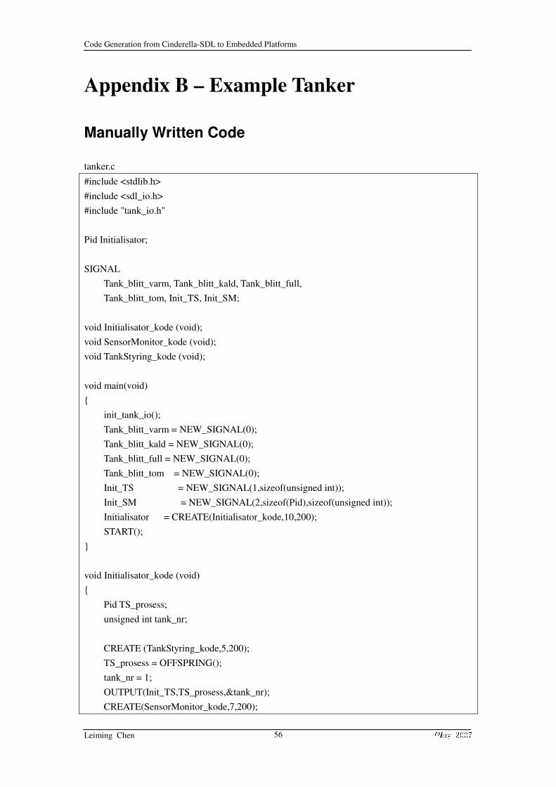
Code Generation from Cinderella-SDL to Embedded Platforms
Leiming Chen ©May 2007 56
Appendix B – Example Tanker
Manually Written Code
tanker.c
#include <stdlib.h>
#include <sdl_io.h>
#include "tank_io.h"
Pid Initialisator;
SIGNAL
Tank_blitt_varm, Tank_blitt_kald, Tank_blitt_full,
Tank_blitt_tom, Init_TS, Init_SM;
void Initialisator_kode (void);
void SensorMonitor_kode (void);
void TankStyring_kode (void);
void main(void)
{
init_tank_io();
Tank_blitt_varm = NEW_SIGNAL(0);
Tank_blitt_kald = NEW_SIGNAL(0);
Tank_blitt_full = NEW_SIGNAL(0);
Tank_blitt_tom = NEW_SIGNAL(0);
Init_TS = NEW_SIGNAL(1,sizeof(unsigned int));
Init_SM = NEW_SIGNAL(2,sizeof(Pid),sizeof(unsigned int));
Initialisator = CREATE(Initialisator_kode,10,200);
START();
}
void Initialisator_kode (void)
{
Pid TS_prosess;
unsigned int tank_nr;
CREATE (TankStyring_kode,5,200);
TS_prosess = OFFSPRING();
tank_nr = 1;
OUTPUT(Init_TS,TS_prosess,&tank_nr);
CREATE(SensorMonitor_kode,7,200);

Code Generation from Cinderella-SDL to Embedded Platforms
Leiming Chen ©May 2007 57
OUTPUT(Init_SM,OFFSPRING(),&TS_prosess,&tank_nr);
CREATE (TankStyring_kode,5,200);
TS_prosess = OFFSPRING();
tank_nr = 2;
OUTPUT(Init_TS,TS_prosess,&tank_nr);
CREATE(SensorMonitor_kode,7,200);
OUTPUT(Init_SM,OFFSPRING(),&TS_prosess,&tank_nr);
STOP();
}
void SensorMonitor_kode (void)
{
Pid min_tank;
int tank_nr;
boolean er_aktiv, tank_var_varm, tank_var_tom, tank_var_full;
TIMER tid_for_sjekk;
enum{Venter_init_data, Venter} tilstand = Venter_init_data;
tid_for_sjekk = NEW_TIMER();
while(1)
{
switch(tilstand)
{
case Venter_init_data:
INPUT(Init_SM, END_LIST);
SAVE(NONE);
WAIT_SIGNAL();
GET_SIGNAL_DATA(&min_tank,&tank_nr);
tank_var_varm= false;
tank_var_tom = false;
tank_var_full = false;
SET(10, tid_for_sjekk);
tilstand = Venter;
break;
case Venter:
INPUT(tid_for_sjekk, END_LIST);
SAVE(NONE);
WAIT_SIGNAL();
SET(10, tid_for_sjekk);
tank_tom(tank_nr, &er_aktiv);
if (er_aktiv && !tank_var_tom)
OUTPUT(Tank_blitt_tom, min_tank);
tank_var_tom = er_aktiv;
tank_full(tank_nr, &er_aktiv);

Code Generation from Cinderella-SDL to Embedded Platforms
Leiming Chen ©May 2007 58
if (er_aktiv && !tank_var_full)
OUTPUT(Tank_blitt_full, min_tank);
tank_var_full = er_aktiv;
tank_varm(tank_nr, &er_aktiv);
if (er_aktiv)
{
if(!tank_var_varm)
OUTPUT(Tank_blitt_varm, min_tank);
}
else
{
if(tank_var_varm)
OUTPUT(Tank_blitt_kald, min_tank);
}
tank_var_varm = er_aktiv;
break;
}
}
}
void TankStyring_kode (void)
{
int tank_nr;
enum {Venter_init_data,Venter_paa_tom,Fyller,Varmer,Vedlikeholder}
tilstand = Venter_init_data;
SIGNAL mottatt;
while (1)
{
switch (tilstand){
case Venter_init_data:
INPUT(Init_TS, END_LIST);
SAVE(NONE);
WAIT_SIGNAL();
GET_SIGNAL_DATA(&tank_nr);
varme_av(tank_nr);
kran_av(tank_nr);
tilstand = Venter_paa_tom;
break;
case Venter_paa_tom:
INPUT(Tank_blitt_tom, END_LIST);
SAVE(NONE);
WAIT_SIGNAL();

Code Generation from Cinderella-SDL to Embedded Platforms
Leiming Chen ©May 2007 59
kran_paa(tank_nr);
tilstand = Fyller;
break;
case Fyller :
INPUT(Tank_blitt_full, END_LIST);
SAVE(NONE);
WAIT_SIGNAL();
kran_av(tank_nr);
varme_paa(tank_nr);
tilstand = Varmer;
break;
case Varmer :
INPUT(Tank_blitt_varm, Tank_blitt_tom, END_LIST);
SAVE(NONE);
mottatt = WAIT_SIGNAL();
if (mottatt == Tank_blitt_varm)
{
varme_av(tank_nr);
tilstand = Vedlikeholder;
}
else /* if (mottatt == Tank_blitt_tom) */
{
varme_av(tank_nr);
kran_paa(tank_nr);
tilstand = Fyller;
}
break;
case Vedlikeholder :
INPUT(Tank_blitt_kald, Tank_blitt_tom, END_LIST);
SAVE(NONE);
mottatt = WAIT_SIGNAL();
if (mottatt == Tank_blitt_kald)
{
varme_paa(tank_nr);
tilstand = Varmer;
}
else /* if (Tank_blitt_tom) */
{
kran_paa(tank_nr);
tilstand = Fyller;
}

Code Generation from Cinderella-SDL to Embedded Platforms
Leiming Chen ©May 2007 60
break;
}
}
}
tanker_io.c
#include "tank_io.h"
#include <sdl_io.h>
#define tank_1_tom 0x01
#define tank_1_full 0x02
#define tank_1_varm 0x04
#define tank_2_tom 0x10
#define tank_2_full 0x20
#define tank_2_varm 0x40
#define kran_1 0x01
#define varme_1 0x02
#define kran_2 0x10
#define varme_2 0x20
static unsigned char lamper;
void tank_tom( int tank_nr, boolean * aktiv)
{
switch (tank_nr) {
case 1 :
*aktiv = ((switchRead() & tank_1_tom) != 0);
break;
case 2 :
*aktiv = ((switchRead() & tank_2_tom) != 0);
break;
default :
*aktiv = false;
break;
}
} /* END tank_tom */
void tank_full( int tank_nr, boolean * aktiv)
{
switch (tank_nr)
{
case 1 :
*aktiv = ((switchRead() & tank_1_full) != 0);
break;

Code Generation from Cinderella-SDL to Embedded Platforms
Leiming Chen ©May 2007 61
case 2 :
*aktiv = ((switchRead() & tank_2_full) != 0);
break;
default :
*aktiv = false;
break;
}
} /* END tank_full */
void tank_varm( int tank_nr, boolean * aktiv) {
switch (tank_nr)
{
case 1 :
*aktiv = ((switchRead() & tank_1_varm) != 0);
break;
case 2 :
*aktiv = ((switchRead() & tank_2_varm) != 0);
break;
default :
*aktiv = false;
break;
}
} /* END tank_varm */
void kran_paa ( int tank_nr)
{
switch (tank_nr)
{
case 1 : lamper |= kran_1; break;
case 2 : lamper |= kran_2; break;
}
OUTPUT(LED_WRITE, ENV, &lamper);
} /* END kran_paa */
void kran_av ( int tank_nr)
{
switch (tank_nr)
{
case 1 : lamper &= ~kran_1; break;
case 2 : lamper &= ~kran_2; break;
}
OUTPUT(LED_WRITE, ENV, &lamper);
} /* END kran_av */

Code Generation from Cinderella-SDL to Embedded Platforms
Leiming Chen ©May 2007 62
void varme_paa ( int tank_nr)
{
switch (tank_nr)
{
case 1 : lamper |= varme_1; break;
case 2 : lamper |= varme_2; break;
}
OUTPUT(LED_WRITE, ENV, &lamper);
} /* END varme_paa */
void varme_av ( int tank_nr)
{
switch (tank_nr)
{
case 1 : lamper &= ~varme_1; break;
case 2 : lamper &= ~varme_2; break;
}
OUTPUT(LED_WRITE, ENV, &lamper);
} /* END varme_av */
void init_tank_io (void)
{
lamper = 0;
OUTPUT(LED_WRITE, ENV, &lamper);
} /* END init_tank_io */
tanker_io.h
#ifndef TANK_IO_H
#define TANK_IO_H
typedef enum {false,true} boolean;
void tank_tom( int tank_nr, boolean * aktiv);
void tank_full( int tank_nr, boolean * aktiv);
void tank_varm( int tank_nr, boolean * aktiv);
void kran_paa ( int tank_nr);
void kran_av ( int tank_nr);
void varme_paa ( int tank_nr);
void varme_av ( int tank_nr);
void init_tank_io (void);
#endif /* TANK_IO_H */
Generated Code
tanker.c
#include <stdlib.h>

Code Generation from Cinderella-SDL to Embedded Platforms
Leiming Chen ©May 2007 63
#include <sdl_io.h>
#include <string.h>
#include "tanker.h"
typedef unsigned int natural;
typedef enum{false, true} boolean;
typedef unsigned int integer;
typedef unsigned char character;
typedef char charstring[20];
typedef float duration;
typedef float time;
typedef float real;
Pid initialisator, sensormonitor, tankstyring;
SIGNAL tid_for_sjekk, init_ts, init_sm, tank_blitt_tom, tank_blitt_full,
tank_blitt_kald, tank_blitt_varm;
void initialisator_code(void);
void sensormonitor_code(void);
void tankstyring_code(void);
int main(void)
{
tid_for_sjekk = NEW_SIGNAL(0);
init_ts = NEW_SIGNAL(1, sizeof(natural));
init_sm = NEW_SIGNAL(2, sizeof(Pid), sizeof(natural));
tank_blitt_tom = NEW_SIGNAL(0);
tank_blitt_full = NEW_SIGNAL(0);
tank_blitt_kald = NEW_SIGNAL(0);
tank_blitt_varm = NEW_SIGNAL(0);
initialisator = CREATE(initialisator_code, initialisator_pri, initialisator_size);
START();
return 0;
}
//**************tanker_system block start****************
//**************initialisator process start*****************
void init_tank_io (void);
void initialisator_code(void)
{
Pid ts_prosess;
natural temp1;
natural temp2;

Code Generation from Cinderella-SDL to Embedded Platforms
Leiming Chen ©May 2007 64
SIGNAL receive;
temp1 = 1;
temp2 = 2;
init_tank_io();
CREATE(tankstyring_code, tankstyring_pri, tankstyring_size);
ts_prosess = OFFSPRING();
OUTPUT(init_ts, ts_prosess, &temp1);
CREATE(sensormonitor_code, sensormonitor_pri, sensormonitor_size);
OUTPUT(init_sm, OFFSPRING(), &ts_prosess, &temp1);
CREATE(tankstyring_code, tankstyring_pri, tankstyring_size);
ts_prosess = OFFSPRING();
OUTPUT(init_ts, ts_prosess, &temp2);
CREATE(sensormonitor_code, sensormonitor_pri, sensormonitor_size);
OUTPUT(init_sm, OFFSPRING(), &ts_prosess, &temp2);
STOP();
}
void init_tank_io (void)
{
natural lamper;
lamper = 0;
OUTPUT(LED_WRITE, ENV, &lamper);
}
//**************initialisator process end*****************
//**************sensormonitor process start**************
void tank_varm(natural tank_nr, boolean *aktiv);
void tank_full(natural tank_nr, boolean *aktiv);
void tank_tom(natural tank_nr, boolean *aktiv);
void sensormonitor_code(void)
{
Pid min_tank;
natural tank_nr;
boolean er_aktiv;
boolean tank_var_varm;
boolean tank_var_tom;
boolean tank_var_full;
TIMER tid_for_sjekk = NEW_TIMER();
enum{venter, venter_init_data} current_state = venter;
SIGNAL receive;
current_state = venter_init_data;
while (1)
{
switch (current_state)
{
case venter:

Code Generation from Cinderella-SDL to Embedded Platforms
Leiming Chen ©May 2007 65
{
INPUT(tid_for_sjekk, END_LIST);
SAVE(NONE);
receive = WAIT_SIGNAL();
if (receive == tid_for_sjekk)
{
SET((unsigned int)(0.1*timer_standard), tid_for_sjekk);
tank_tom(tank_nr, &er_aktiv);
if (er_aktiv && !(tank_var_tom))
OUTPUT(tank_blitt_tom, min_tank);
tank_var_tom = er_aktiv;
tank_full(tank_nr, &er_aktiv);
if (er_aktiv && !(tank_var_full))
OUTPUT(tank_blitt_full, min_tank);
tank_var_full = er_aktiv;
tank_varm(tank_nr, &er_aktiv);
if ((er_aktiv) == false)
{
if (tank_var_varm)
OUTPUT(tank_blitt_kald, min_tank);
tank_var_varm = er_aktiv;
current_state = venter;
}
else if ((er_aktiv) == true)
{
if (!(tank_var_varm))
OUTPUT(tank_blitt_varm, min_tank);
tank_var_varm = er_aktiv;
current_state = venter;
}
}
}
break;
case venter_init_data:
{
INPUT(init_sm, END_LIST);
SAVE(NONE);
receive = WAIT_SIGNAL();
if (receive == init_sm)
{
GET_SIGNAL_DATA(&min_tank, &tank_nr);
tank_var_varm = false;
tank_var_tom = false;
tank_var_full = false;

Code Generation from Cinderella-SDL to Embedded Platforms
Leiming Chen ©May 2007 66
SET((unsigned int)(0.1*timer_standard), tid_for_sjekk);
current_state = venter;
}
}
break;
default:
break;
}
}
}
void tank_varm(natural tank_nr, boolean *aktiv)
{
switch (tank_nr)
{
case 1 :
*aktiv = ((switchRead() & tank_1_varm) != 0);
break;
case 2 :
*aktiv = ((switchRead() & tank_2_varm) != 0);
break;
default :
*aktiv = false;
break;
}
}
void tank_full(natural tank_nr, boolean *aktiv)
{
switch (tank_nr)
{
case 1 :
*aktiv = ((switchRead() & tank_1_full) != 0);
break;
case 2 :
*aktiv = ((switchRead() & tank_2_full) != 0);
break;
default :
*aktiv = false;
break;
}
}
void tank_tom(natural tank_nr, boolean *aktiv)

Code Generation from Cinderella-SDL to Embedded Platforms
Leiming Chen ©May 2007 67
{
switch (tank_nr) {
case 1 :
*aktiv = ((switchRead() & tank_1_tom) != 0);
break;
case 2 :
*aktiv = ((switchRead() & tank_2_tom) != 0);
break;
default :
*aktiv = false;
break;
}
}
//**************sensormonitor process end**************
//**************tankstyring process start****************
void varme_av(natural tank_nr);
void varme_paa(natural tank_nr);
void kran_av(natural tank_nr);
void kran_paa(natural tank_nr);
void tankstyring_code(void)
{
natural tank_nr;
enum{varmer, fyller, vedlikeholder, venter_paa_tom, venter_init_data}
current_state = venter_init_data;
SIGNAL receive;
current_state = venter_init_data;
while (1)
{
switch (current_state)
{
case varmer:
{
INPUT(tank_blitt_tom, tank_blitt_varm, END_LIST);
SAVE(NONE);
receive = WAIT_SIGNAL();
if (receive == tank_blitt_tom)
{
varme_av(tank_nr);
kran_paa(tank_nr);
current_state = fyller;
}
else if (receive == tank_blitt_varm)
{
varme_av(tank_nr);

Code Generation from Cinderella-SDL to Embedded Platforms
Leiming Chen ©May 2007 68
current_state = vedlikeholder;
}
}
break;
case fyller:
{
INPUT(tank_blitt_full, END_LIST);
SAVE(NONE);
receive = WAIT_SIGNAL();
if (receive == tank_blitt_full)
{
kran_av(tank_nr);
varme_paa(tank_nr);
current_state = varmer;
}
}
break;
case vedlikeholder:
{
INPUT(tank_blitt_tom, tank_blitt_kald, END_LIST);
SAVE(NONE);
receive = WAIT_SIGNAL();
if (receive == tank_blitt_tom)
{
kran_paa(tank_nr);
current_state = fyller;
}
else if (receive == tank_blitt_kald)
{
varme_paa(tank_nr);
current_state = varmer;
}
}
break;
case venter_paa_tom:
{
INPUT(tank_blitt_tom, END_LIST);
SAVE(NONE);
receive = WAIT_SIGNAL();
if (receive == tank_blitt_tom)
{
kran_paa(tank_nr);
current_state = fyller;
}
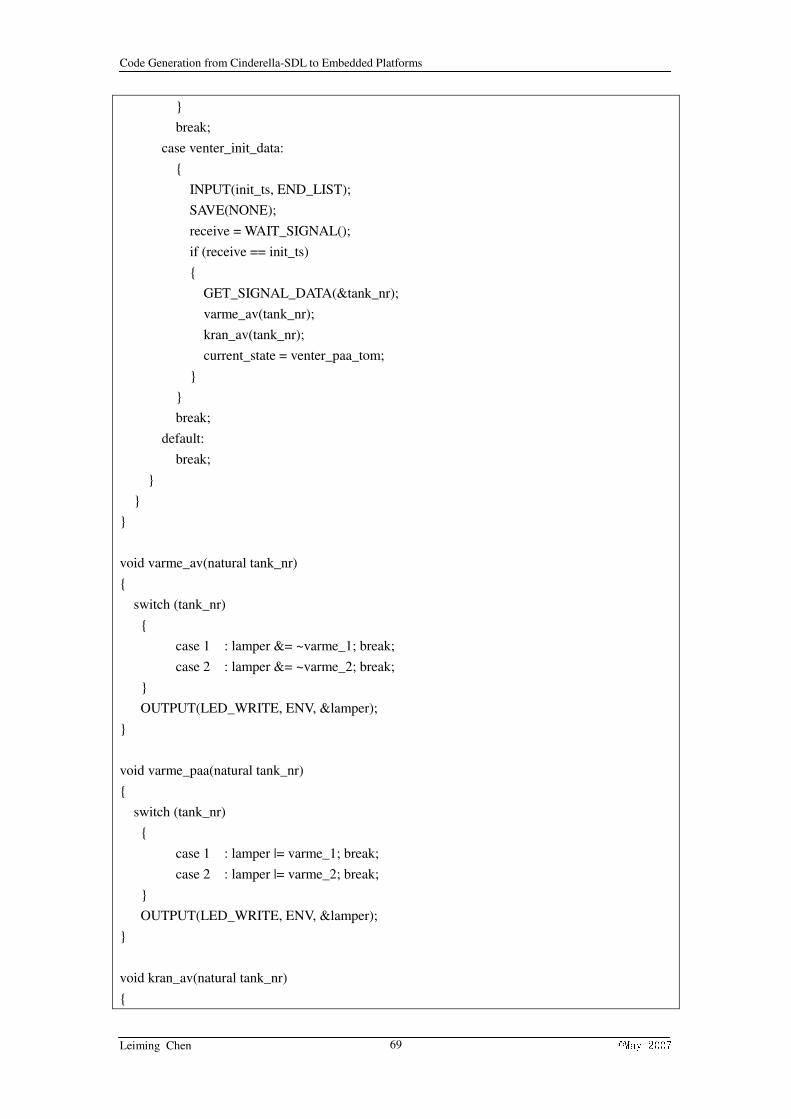
Code Generation from Cinderella-SDL to Embedded Platforms
Leiming Chen ©May 2007 69
}
break;
case venter_init_data:
{
INPUT(init_ts, END_LIST);
SAVE(NONE);
receive = WAIT_SIGNAL();
if (receive == init_ts)
{
GET_SIGNAL_DATA(&tank_nr);
varme_av(tank_nr);
kran_av(tank_nr);
current_state = venter_paa_tom;
}
}
break;
default:
break;
}
}
}
void varme_av(natural tank_nr)
{
switch (tank_nr)
{
case 1 : lamper &= ~varme_1; break;
case 2 : lamper &= ~varme_2; break;
}
OUTPUT(LED_WRITE, ENV, &lamper);
}
void varme_paa(natural tank_nr)
{
switch (tank_nr)
{
case 1 : lamper |= varme_1; break;
case 2 : lamper |= varme_2; break;
}
OUTPUT(LED_WRITE, ENV, &lamper);
}
void kran_av(natural tank_nr)
{

Code Generation from Cinderella-SDL to Embedded Platforms
Leiming Chen ©May 2007 70
switch (tank_nr)
{
case 1 : lamper &= ~kran_1; break;
case 2 : lamper &= ~kran_2; break;
}
OUTPUT(LED_WRITE, ENV, &lamper);
}
void kran_paa(natural tank_nr)
{
switch (tank_nr)
{
case 1 : lamper |= varme_1; break;
case 2 : lamper |= varme_2; break;
}
OUTPUT(LED_WRITE, ENV, &lamper);
}
//**************tankstyring process end***************
//**************tanker_system block end**************
tanker.h
#ifndef tanker_h
#define tanker_h
#define initialisator_pri 5
#define initialisator_size 100
#define sensormonitor_pri 5
#define sensormonitor_size 100
#define tankstyring_pri 5
#define tankstyring_size 100
#define timer_standard 1000
#endif
Top Related