


Languages
Pages
Legal


Abstract-- Overcurrent relays (OCRs) are one of the most
common protective devices implemented in power systems to
protect electrical components from faults. In order to obtain
much improved protection by these protective devices, a
precise coordination of these systems must be applied. One of
the problems in power systems, which is very common, is when
a fault occurs in a plant, and two, three or even several OCRs
operate instead of the designated relay at that particular fault
location. In this work, the technical data of 2X15MVA,
33/11KV Maitama injection substation was collected and used
for modelling relay coordination for the station. After the
coordination, the result shows that 33KV feeder will trip on
over current and earth faults if the secondary current of the
CT exceeds 1.32A and 0.264A within 0.021s and 0.00167
respectively. For the 11KV outgoing feeder, it will trip on over
current and earth faults if the secondary current of the CT
exceeds 0.88A and 264mA within 12.5ms and 1.7ms
respectively. From these results, it is noted that earth faults
trip faster than overcurrent fault; this is because of the
harmful nature of earth. If it’s not isolated fast in an
interconnected system, it will cause a lot of damage to both
power system components and personals.
Index Term -- Relay coordination, Interconnected power
system, Tripping unit, Protection, Injection substation
I. INTRODUCTION
or power system to have normal operation without
electrical failure and damage to the equipment, two
alternatives are available to the designer, one is to
design the system so that fault will not occur and the other
is to accept the possibility of faults and take steps to guard
against the ill effects of such faults. It is possible to
minimize fault to a large extent by careful system design,
proper operational coordination and maintenance. It is also
obviously not possible to design a system that is 100% free
from fault,
so the possibility of fault must be accepted and the necessity
of protection scheme must be realised [1]. Since power
system developments change its structure, the power system
protection becomes very vital. As the designer or engineer
of the system struggles with devising a system arrangement,
the engineer simply cannot build a system which will never
fail regardless of any reasons. This is where protection
system and protective relays become important. For
designing the protective relaying, understanding the fault
characteristics is required. Related to this, protection
engineer should be conversant about tripping characteristics
of various protective relays. The designer of protective
relaying has to ensure that relays will be able to detect
abnormal or undesirable conditions and then trip the circuit
breaker to disconnect the affected area without affecting
other undesired areas. Statistical evidence has shown that
large number of relay tripping is caused by improper or
inadequate settings of the device and not just because of
genuine faults [2, 3]
Protection scheme required for the protection of power
system components against abnormal conditions such as
faults, overvoltages, etc. essentially consist of protective
relaying and circuit breaker. Protective relay functions as
monitoring or sensing device, it senses the fault, determines
its location and finally, it sends a tripping command to the
appropriate circuit breaker. The circuit breaker after getting
the command from the protective relay disconnects the
faulted element, thus protective relay which is the brain
behind the protective scheme, plays a vital role. Therefore,
proper care should be taken in designing and selecting an
appropriate protective relay which is reliable, efficient and
fast in operation [1]. This can be very expensive. To reduce
such cost, a balance needs to be struck between the cost of
the protection and the degree of safety to the equipment [4].
Among several power system components, interconnected
power system is one of the most important components of
the power system network and is mostly affected by several
types of faults. Generally, 80 -90% of the faults occur on
interconnected power system and the rest from substation
equipment and bus bar combined [5]. If any fault or
disturbances occurred in an interconnected power system
and is not detected, located, and eliminated quickly, it may
cause instability in the system and causes significant
changes in system quantities like over-current, under or over
voltage, and others. The purpose of this work is to
Co-ordination of Overcurrent Relay in
Interconnected Power System Protection:
Practical Implication, Benefit and Prospects
Uche C. Ogbuefi1, Muncho J. Mbunwe2, John J. Bipialaka3 and Boniface O. Anyaka2, Member,
IAENG
F
Manuscript submitted 29th Apr. 2019, revised 4th June, 2019.
U. C. Ogbuefi is with Department of Electrical Engineering,
University of Nigeria, Nsukka. ([email protected]).
M. J. Mbunwe is with the Department of Electrical Engineering,
University of Nigeria Nsukka, ([email protected]).
John J. Bipialaka is with JIBS Engineering Co., 31-3 Jibs Lane, Off
Ordinance Road, Trans Amadi, PortHarcourt, Rivers State, Nigeria
B. O. Anyaka is also in Electrical Engineering Department of
University of Nigeria, Nsukka. ([email protected]).
Proceedings of the World Congress on Engineering and Computer Science 2019 WCECS 2019, October 22-24, 2019, San Francisco, USA
ISBN: 978-988-14048-7-9 ISSN: 2078-0958 (Print); ISSN: 2078-0966 (Online)
WCECS 2019
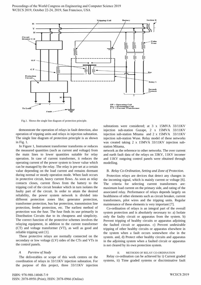
demonstrate the operation of relays in fault detection, also
operation of tripping units and relays in injection substation.
The single line diagram of protection principle is as shown
in Fig. 1.
In Figure 1, Instrument transformer transforms or reduces
the measured quantities (such as current and voltage) from
the main lines to lower quantities suitable for relay
operation. In case of current transformer, it reduces the
operating current of the power system to lower value which
can be managed by the relay. The relay is pre-set at a certain
value depending on the load current and remains dormant
during normal or steady operation mode. When fault occurs
in protective circuit, heavy current flows. As soon as relay
contacts closes, current flows from the battery to the
tripping coil of the circuit breaker which in turn isolates the
faulty part of the circuit. In order to attain the desired
reliability, the power system network is divided into
different protection zones like; generator protection,
transformer protection, bus bar protection, transmission line
protection, feeder protection, etc. The earliest method of
protection was the fuse. The fuse finds its use primarily in
Distribution Circuits due to its cheapness and simplicity.
The correct function of the protective schemes involves the
relaying equipment, in addition to the current transformer
(CT) and voltage transformer (VT), as well as good and
reliable tripping unit [1].
These protective relays are normally connected on the
secondary or low voltage (LV) sides of the CTs and VTs in
the control panels.
A Purview of Study
The deliverables or scope of this work centres on the
coordination of relays in 33/11KV injection substation. For
the purpose of this project, three 33/11KV injection
substations were considered; at 3 x 15MVA 33/11KV
injection sub-station Guzape, 2 x 15MVA 33/11KV
injection sub-station Mitama and 2 x 15MVA 33/11KV
injection sub-station Wuse. Relay model of these networks
was created taking 2 x 15MVA 33/11KV injection sub-
station Mitama,
network as the reference to other networks. The over current
and earth fault data of the relays on 33KV, 11KV incomer
and 11KV outgoing control panels were obtained through
modelling.
B. Relay Co-Ordination, Setting and Zone of Protection.
Protection relays are devices that detect any changes in
the incoming signal, which is mainly current or voltage [6]. The criteria for selecting current transformers are:
maximum load current on the primary side, and rating of the
associated relay. Performance of relays depends largely on
healthiness of other elements such as circuit breaker, current
transformers, pilot wires and the tripping units. Regular
maintenance of these elements is very important [7].
Co-ordination of relays is an integral part of the overall
system protection and is absolutely necessary to: a) Isolate
only the faulty circuit or apparatus from the system. b)
Prevent tripping of healthy circuits or apparatus adjoining
the faulted circuit or apparatus. c) Prevent undesirable
tripping of other healthy circuits or apparatus elsewhere in
the system when a fault occurs somewhere else in the
system. and, d) Protect other healthy circuits and apparatus
in the adjoining system when a faulted circuit or apparatus
is not cleared by its own protection system.
II. METHODS OF RELAY CO-ORDINATION
Relay co-ordination can be achieved by i) Current graded
systems, ii) Time graded systems or discriminative fault
Fig.1. Shows the single line diagram of protection principle.
Proceedings of the World Congress on Engineering and Computer Science 2019 WCECS 2019, October 22-24, 2019, San Francisco, USA
ISBN: 978-988-14048-7-9 ISSN: 2078-0958 (Print); ISSN: 2078-0966 (Online)
WCECS 2019

protection, iii) A combination of time and current grading
methods:
These methods are to give correct discrimination or
selectivity of operation, and each protective system must
select and isolate only the faulty section of the power
system network, leaving the rest of the healthy system
undisturbed. The selectivity and co-ordination is to choose
the correct current and time settings or time delay settings
of each of the relays in the system network [8].
(a) Time Graded Systems
Selectivity is achieved by introducing time intervals for
the relays. The operating time of the relay is increased from
the farthest side to the source towards the generating source
and it is achieved with the help of definite time delay over
current relays. As the number of relays in series increases,
the operating time increases towards the source.
Fig. 3 represents the principle of a time graded over
current system of protection for a radial feeder [9].
From Fig. (3), protection is provided at sections A, B, and
C. Relay at C is set at the shortest time delay in order to
allow the fuse to blow out for a fault in the secondary of the
distribution Transformer D. If 0.3 seconds is the time delay
for relay at C, then for a fault at F1, the relay will operate in
0.3 seconds.
Relays at A, B and S do not operate, but these relays only
act as back up Protection relays. For a fault at F2, the fuses
blow out in say 0.1 seconds and if they fail to blow out then
the relay at C operates to clear the fault in 0.3 seconds.
(b) Current Graded Systems
This principle is based on the fact that the fault current
varies with the position of the fault because of the
difference in impedance values between the source and the
fault. The relays are set to pick up at progressively higher
currents towards the source.
A simple current graded scheme applied to the system as
shown in Fig. (3) consist of high set over current relays at S,
A, B and C such that the relay at S would operate for faults
between S and A; the relay at A would operate for faults
between A and B and so on. Thus discriminating by current
grading alone is not a practical proposition for exact
grading. As such current grading alone is not used, but may
be used to advantage along with a Time Graded System [9,
10]. The relay should not be so expensive as to outweigh the
benefit of using it to protect the associated equipment [11].
(c) Time and Current Graded System
The limitations imposed by the independent use of either
time or current graded systems are avoided by using a
combination of time and current graded systems. It is for
this purpose that over current relays with inverse time
characteristics are used. The time interval of operation
between two adjacent relays depends upon a number of
factors like: the fault current interrupting time of the circuit
breaker, the overshoot time of the relay, Variation in
measuring devices errors and Factor of Safety [9].
Factor of Safety
Some safety margin is intentionally introduced to account
for errors and delays in breaker operating time. The Phase-
to-Phase fault current should be considered for phase fault
relays and the phase to earth fault current for earth fault
relays. In the examples that follow, we shall limit ourselves
to 100% setting and it is advisable that we don’t exceed this
value most especially for transformer protection [12].
A. Setting of Relay(S) In An Inter Connected System
The setting for over current fault (short circuit or phase to
phase fault) relay is usually of the order of 120-200% of the
full-load current. A protective relay will not operate at a
current equal or less than its setting and minimum operating
current of the relay must not exceed 130% of the setting.
For the earth fault (phase-to- ground fault) relay setting, the
range of 20-80% of the over current fault is maintained.
This is because, earth fault is more dangerous than the over
current fault. An earth fault relay is subjected to
maloperation if its setting is too low.
A time interval of 0.4 to 0.5 seconds may be allowed in
the time setting of two adjacent protective relays for the
selectivity shorter interval of 0.35 seconds, may be used
with very inverse over current relays. Operating time of
proactive relay is an important quantity to be determined
before setting a protective relay. For relay setting and
coordination, the following data are required: i) Time-plug
setting multiplier curve (Time-PSM curve), ii) Current
setting, iii) Time setting, iv) Fault Current, v) Current
Transformer ratio, vi) Actual operating time of the relay.
The actual operating time of a relay is determined as
follows:
i. Determination of relay current from fault current,
If, and current transformer ratio x : y is given as:
Relay current, x
yII
f
R
(1)
Where x and y are the secondary and primary current of the
CT respectively and fI is the fault current.
ii. Determination of relay current plug setting multiplier
(i.e P.S.M) is given by:
Fig. 3: Principle of a time graded over current system of protection
Proceedings of the World Congress on Engineering and Computer Science 2019 WCECS 2019, October 22-24, 2019, San Francisco, USA
ISBN: 978-988-14048-7-9 ISSN: 2078-0958 (Print); ISSN: 2078-0966 (Online)
WCECS 2019

valueupPick
relaycoilincurrentfaultPSM
(2)
CT theofcurrent secondary retatedsettingCurrent RI
(3)
iii. Determination of operation time of relay
corresponding to calculated PSM from Time-PSM curve.
Determination of actual operating time of relay by
multiplying the time obtained in step (iii) by the time
setting multiplier in use [13].
A. Zones of Protection
For effective protection of the system with minimum part
disconnected during fault, protection zones are mapped out.
These zones are created in such a way that each overlap
around an isolating device such as a circuit breaker. The
method guarantees total protection of power system sub
circuits. For such boundaries to be genuine there must be:
Measuring devices such as Current Transformer or
Voltage Transformer.
Isolating devices such as breakers.
III. METHOD
The technique used in this work is the analytical approach.
The technical data of 2X15MVA, 33/11KV Maitama
injection substation was collected and used for modelling
relay coordination. The data was used to model and
coordinate IDMT Micom relay that monitor earth fault and
over current fault of 33KV control panels, incomer control
panels, and 11KV control panels in the injection sub-station.
Table 3.1 shows the technical data of 2X15MVA, 33/11KV
considered injection substation.
Data in Table 1 was used to set and coordinate the IDMT
Micom relay that monitors the earth fault and over current
fault of the 33KV control panels, incomer control panels
and 11KV control panels in the injection sub-station. The
fault current and fault MVA of the line are obtained using
Eqs. (4 & 5)
KVBase
MVAFaultCurrentFault
3
103
(4)
... eqUPX
MVABaseMVAFault
(5)
Where: ... eqUPX is the per unit reactant equivalent up to the
point of fault, MVAFault is the fault apparent power of
the station in Mega volt-ampere, MVABase is the base
apparent power of the station in Mega volt-ampere, and
KVBase Is the base voltage of the station in Kilo-volt.
The technical data indicates that there are two 2 x 15MVA
transformers in the injection substation; this implies that the
33KV feeder control panel will be two (2) plus the spear(s).
The transformer incomer control panel will also be two (2)
plus the spear(s). The number of 11KV outgoing feeder
control panel depends on the CT ratio of the transformer
incomer control panel. Per unit equivalent inductance of the
feeder, %,80... eqUPX fault MVA is calculated as
187.5.while the fault current associated with 33KV and
11kV control panel using Eq. 4 are approximately 3280.4A
and 9841.2A respectively. Since same voltage flows
through the 11KV control panel and the outgoing panel,
same fault current will flow across the panel during the
event of abnormal condition. Thus its fault is A2.9841 .
As the rating of the transformers are the same, one
transformer will be use to get the parameters needed to set
the relay. While setting the Micom relay, the parameters
used in the setting are: tying
greater.-Ior current Over I,
current.over for operation of timeActualtI
greater.-greater-Ior current over DoubleI
current.
over doublefor operation of timeActualtI
greater.-
greater-greater-Ior current over TripleI
current.over
for tripleoperation of timeActualtI
greater.-Ior fault Earth eeI
fault.earth for operation of timeActualetI,
greater.-greater-Ieor fault Earth DoubleeI
fault.earth
doublefor operation of timeActualetI
greater.-greater-
greater-Ieor fault Earth TripleeI
fault.earth
for tripleoperation of timeActualetI
.Multiplier Setting TimeTMS
TABLE I
TECHNICAL DATA OF 2X15MVA, 33/11KV MAITAMA
INJECTION SUBSTATION
Proceedings of the World Congress on Engineering and Computer Science 2019 WCECS 2019, October 22-24, 2019, San Francisco, USA
ISBN: 978-988-14048-7-9 ISSN: 2078-0958 (Print); ISSN: 2078-0966 (Online)
WCECS 2019
.Multiplier Setting PlugPSM
The transformation ratio of the transformer is “a” and was
calculated as 3. Likewise the primary current of the
transformer ‘I1’ is 262.2A and the secondary current I2’ is
787.29A
From the above calculations, the maximum current of the
primary and secondary sides of the transformer are
approximately 262A and 787A respectively.
A. Modelling of parameters for 33KV relay control panel
Parameters to be used for the relay setting on the 33KV
feeder control panels for over current and earth fault are
calculated thus; from Eq. 1 that is x
yII
f
R
Where If
= 3280.4 A, CT ratio = 600:1A , relay current IR = 5.5A,
relay Pick-up value is 1.25A, PSM is obtained as 4.4
The time that corresponds to the PSM of 4.4 is 1.2
seconds, relay operating time is 0.03 second.
Now,
AisI 44.0 , seconds, 0.025 istI
,88.02 AiswhichII
ondsequalstI sec021.0
The earth fault is set to be 20% of the over current,
and the operating time to be 20% of operation time of
over current fault relay.
So, Ie> = 20% of I> Agives 088.0 , tIe> = 20% of tI>
ondsgiveswhich sec005.0 , Ie>> = 2 x Ie> gives
0.176A, tIe>> ondsyields sec0025.0
Ie>>>= 3 x Ie>= 3 x 0.088 = 0.264A, tIe>>>
ondsequals sec00167.0 . The results are as shown
in Table 2
B Modelling of parameters for 33KV relay control
panel
From Eq. (1), x
yII
f
R
Where If = 10000A, CT ratio
= 1200:1A
Therefore, relay current, x
yII
f
R
gives 8.33A. Pick-
up value of relay = current setting x rated secondary current
of the CT given 1.25A
Plug setting multiplier of the relay, PSM is:
664.6
relay theof valueup-Pick
I coil,relay in thecurrent Fault R
is
PSM
Suppose the time that corresponds to the PSM of 6.664 is
2.5seconds, the actual operating time of the relay is = 2.5 x
Time Setting Multiplier (TSM) which gives 0.0625seconds.
the parameters that will be use in the relay setting are
calculated and the values as presented in Tables 3 & 4.
The earth fault is set to be 20% of the over current fault and
the operating time to be 20% of operation time of over
current fault.
Then, Ie> = 20% of I> = 0.132A, tIe> = 20% of tI> =
0.005secoonds, Ie>> = 2 x Ie>= 2 x 0.132 = 0.264A, tIe>>=
0.0025seconds, Ie>>>= 3 x Ie> = 0.396A, tIe>> = 0.00167
seconds
C Modelling of parameters for outgoing relay control
panel
Relay current, x
yII
f
R
= 5.83A,
Pick-up value of relay = current setting x rated secondary
current of the CT which is 1.25A, and PSM was calculated
as 5.
Note, the outgoing feeders will share the current on the
incomer control panel. Assuming that we have three (3)
outgoing feeders, the load on each feeder will be: 787:3A
equals 262A
Since these outgoing feeders have the same type of relay,
one of them will be used to calculate the parameter for
setting of the relays. The relay setting parameters are
calculated as: AI 44.0, TSM = 0.025seconds,
AII 66.05.1 , tI>> = o.0167seconds
AII 88.02 , ondstI sec0125.0
.
We set earth fault to be 20% of the over current fault and
the operating time to be 20% of operation time of over
current fault. Then, Ie> = 20% of I> which gives 0.088A
tIe> = 20% of tI> equals 0.005seconds, Ie>> = 2 x Ie> = 0.18A,
tIe>> 0.0024seconds.
Ie>>>= 3 x Ie> = 0.264A, and tIe>>= 0.00164seconds.
D Maintenance of Relays
Maintaining protective relays will ensure the maximum
degree of protection for the power system network. After
protective relay has been installed, deterioration may take
place, such as rough or burnt contacts owing to frequent
operation, or contacts may become tarnished because of
atmospheric contamination. Defects may have developed
unnoticed until it is revealed by the failure of the protection
device to respond to a power system fault. For these
reasons, all relays must be checked periodically.
IV. RELAY COORDINATION RESULTS AND DISCUSSION
a) The parameters for the 33KV relay setting
Since there are two (2) numbers 15 MVA transformers,
there will be two (2) numbers 33KV feeder control panels
and a spare. The parameters for the 33KV relay setting are
summarized in the Table
Proceedings of the World Congress on Engineering and Computer Science 2019 WCECS 2019, October 22-24, 2019, San Francisco, USA
ISBN: 978-988-14048-7-9 ISSN: 2078-0958 (Print); ISSN: 2078-0966 (Online)
WCECS 2019
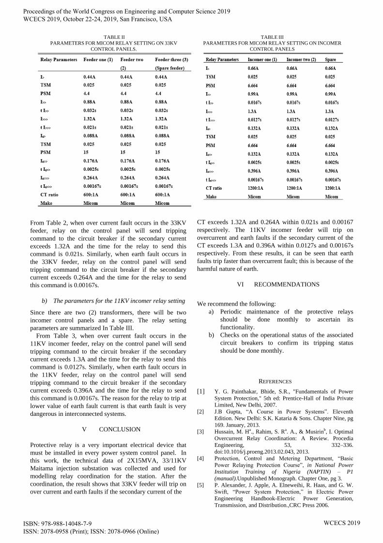
From Table 2, when over current fault occurs in the 33KV
feeder, relay on the control panel will send tripping
command to the circuit breaker if the secondary current
exceeds 1.32A and the time for the relay to send this
command is 0.021s. Similarly, when earth fault occurs in
the 33KV feeder, relay on the control panel will send
tripping command to the circuit breaker if the secondary
current exceeds 0.264A and the time for the relay to send
this command is 0.00167s.
b) The parameters for the 11KV incomer relay setting
Since there are two (2) transformers, there will be two
incomer control panels and a spare. The relay setting
parameters are summarized In Table III.
From Table 3, when over current fault occurs in the
11KV incomer feeder, relay on the control panel will send
tripping command to the circuit breaker if the secondary
current exceeds 1.3A and the time for the relay to send this
command is 0.0127s. Similarly, when earth fault occurs in
the 11KV feeder, relay on the control panel will send
tripping command to the circuit breaker if the secondary
current exceeds 0.396A and the time for the relay to send
this command is 0.00167s. The reason for the relay to trip at
lower value of earth fault current is that earth fault is very
dangerous in interconnected systems.
V CONCLUSION
Protective relay is a very important electrical device that
must be installed in every power system control panel. In
this work, the technical data of 2X15MVA, 33/11KV
Maitama injection substation was collected and used for
modelling relay coordination for the station. After the
coordination, the result shows that 33KV feeder will trip on
over current and earth faults if the secondary current of the
CT exceeds 1.32A and 0.264A within 0.021s and 0.00167
respectively. The 11KV incomer feeder will trip on
overcurrent and earth faults if the secondary current of the
CT exceeds 1.3A and 0.396A within 0.0127s and 0.00167s
respectively. From these results, it can be seen that earth
faults trip faster than overcurrent fault; this is because of the
harmful nature of earth.
VI RECOMMENDATIONS
We recommend the following:
a) Periodic maintenance of the protective relays
should be done monthly to ascertain its
functionality.
b) Checks on the operational status of the associated
circuit breakers to confirm its tripping status
should be done monthly.
REFERENCES
[1] Y. G. Painthakar, Bhide, S.R., "Fundamentals of Power
System Protection," 5th ed: Prentice-Hall of India Private
Limited, New Delhi, 2007.
[2] J.B Gupta, “A Course in Power Systems”. Eleventh
Edition. New Delhi: S.K. Kataria & Sons. Chapter Nine, pg
169. January, 2013.
[3] Hussain, M. Ha., Rahim, S. Ra. A., & Musirinb, I. Optimal
Overcurrent Relay Coordination: A Review. Procedia
Engineering, 53, 332–336.
doi:10.1016/j.proeng.2013.02.043, 2013.
[4] Protection, Control and Metering Department, “Basic
Power Relaying Protection Course”, in National Power
Institution Training of Nigeria (NAPTIN) – P1
(manual).Unpublished Monograph. Chapter One, pg 3.
[5] P. Alexander, J. Apple, A. Elneweihi, R. Haas, and G. W.
Swift, “Power System Protection,” in Electric Power
Engineering Handbook-Electric Power Generation,
Transmission, and Distribution.,CRC Press 2006.
TABLE III
PARAMETERS FOR MICOM RELAY SETTING ON INCOMER
CONTROL PANELS
TABLE II
PARAMETERS FOR MICOM RELAY SETTING ON 33KV
CONTROL PANELS.
Proceedings of the World Congress on Engineering and Computer Science 2019 WCECS 2019, October 22-24, 2019, San Francisco, USA
ISBN: 978-988-14048-7-9 ISSN: 2078-0958 (Print); ISSN: 2078-0966 (Online)
WCECS 2019
[6] Paithankar, Y. G., & Bhide, S. R. (2010). Fundamentals of
power system protection. PHI Learning Pvt. Ltd
[7] C. Bernard, “Protection, Methods and control of electricity
system” in a paper presented at the First Conference of
Electricity Supply Authorities and Allied Industries,
Maiduguri. August, 25th-27th.Unpublished
Monograph.pg147-152.
[8] Mohammadi, R., Abyaneh, H. A., Rudsari, H. M., Fathi, S.
H., & Rastegar, H. ‘’Overcurrent relays coordination
considering the priority of constraints’’, Power Delivery,
IEEE Transactions on, 26(3), 1927-1938, 2011.
[9] S. H. Horowitz, “Transmission Line Protection,”in Electric
Power Engineering Handbook-Electric Power Generation,
Transmission, and Distribution.,CRC Press 2006.
[10] Moirangthem, J., Krishnanand, K. R., & Saranjit, N.
Optimal coordination of overcurrent relay using an
enhanced discrete differential evolution algorithm in a
distribution system with DG. In Energy, Automation, and
Signal (ICEAS), 2011 International Conference on (pp. 1-
6). IEEE., December, 2011.
[11] PC&M, “Basic Power Relaying Protection Course”, in
National Power Institution Training of Nigeria (NAPTIN) –
P1 (manual).Unpublished Monograph. Chapter One, pg 7-
11, 63-68.
[12] M.N. Nwohu, “Modelling of Power Systems Component
(EEE 531)”, in power system protection, a lecture
presented in Electrical Engineering University of Nigeria
Nsukka on December, 15th.Unpublished Monograph.
[13] J.B. Gupta, “A Course in Power Systems”. Eleventh
Edition. New Delhi: S.K. Kataria & Sons. Chapter Nine
[9], pg 171. January, 2013.
Proceedings of the World Congress on Engineering and Computer Science 2019 WCECS 2019, October 22-24, 2019, San Francisco, USA
ISBN: 978-988-14048-7-9 ISSN: 2078-0958 (Print); ISSN: 2078-0966 (Online)
WCECS 2019
Top Related