


Languages
Pages
Legal

CHAPTER 6
Cisco IOS XR Security
It is important to control access to the router to prevent unauthorized or malicious usethat might take the router offline or use it to launch an attack on the rest of the network.Cisco IOS XR provides the authentication, authorization, and accounting (AAA) frame-work that helps provide secure access via the logical vty and the physical tty ports. Fur-thermore, ensuing sections in this chapter discuss the concepts of task-basedauthorization and familiarize the user with IOS XR concepts such as admin and SDRplanes as well as the uniqueness of user groups and task group configuration.
Forwarding plane refers to the components involved in the various stages during packetforwarding. Forwarding plane refers not only to the flow of a packet through the routerbut also to the packets destined to the router. Protection of forwarding plane is importantand necessitates controlling the type of traffic that traverses the router, and limiting theamount of traffic that’s destined to the router itself so that the router does not become avictim of a denial of service (DoS) attack. You might well be familiar with access controllists (ACL) and Unicast Reverse Path Forwarding (uRPF) as popular forwarding plane secu-rity features. Additionally, IOS XR has a concept of Local Packet Transport Service(LPTS). LPTS provides protection against traffic destined to the router. This type of trafficis usually related to routing protocols that typically run on the route processor (RP) of therouter, though Telnet, SNMP, NTP, ping, traceroute, and various other services create traf-fic that can be destined to a router’s line card or RP CPU. This chapter discusses the de-tails behind LPTS and highlights key elements of forwarding plane security.
Secure Operating SystemA router running IOS XR is often used as a backbone router providing core routing capa-bilities. Cisco IOS XR might also be used on a provider edge router provisioned with edgeservices such as Layer 2 and Layer 3 VPNs, QoS, and so on. Architectures such as IOS XRoften play a critical role in a service provider (SP) network as a core or an edge device, andits security needs are a paramount concern for the network administrator.
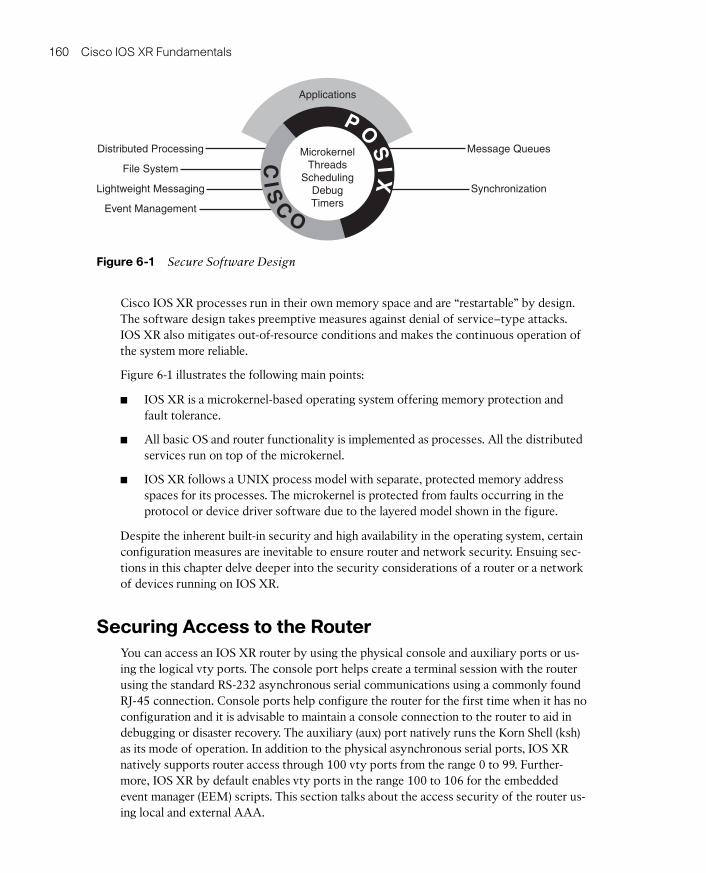
Figure 6-1 shows a visual representation of IOS XR secure software design. IOS XR is amicrokernel-based operating system. All essential services, such as TCP, UDP, and driversoftware, run as an independent application on top of its microkernel. Any individual application-level disaster remains contained and has minimal chances of interfering withthe core functions of the operating systems. This makes IOS XR internals safe and lessvulnerable to exploitation.
07_1587052717_ch06.qxp 5/15/09 11:21 AM Page 159
160 Cisco IOS XR Fundamentals
CIS
C
O
P OS
IX
Distributed Processing
File System
Lightweight Messaging
Event Management
Message Queues
Synchronization
MicrokernelThreads
SchedulingDebugTimers
Applications
Figure 6-1 Secure Software Design
Cisco IOS XR processes run in their own memory space and are “restartable” by design.The software design takes preemptive measures against denial of service–type attacks.IOS XR also mitigates out-of-resource conditions and makes the continuous operation ofthe system more reliable.
Figure 6-1 illustrates the following main points:
■ IOS XR is a microkernel-based operating system offering memory protection andfault tolerance.
■ All basic OS and router functionality is implemented as processes. All the distributedservices run on top of the microkernel.
■ IOS XR follows a UNIX process model with separate, protected memory addressspaces for its processes. The microkernel is protected from faults occurring in theprotocol or device driver software due to the layered model shown in the figure.
Despite the inherent built-in security and high availability in the operating system, certainconfiguration measures are inevitable to ensure router and network security. Ensuing sec-tions in this chapter delve deeper into the security considerations of a router or a networkof devices running on IOS XR.
Securing Access to the RouterYou can access an IOS XR router by using the physical console and auxiliary ports or us-ing the logical vty ports. The console port helps create a terminal session with the routerusing the standard RS-232 asynchronous serial communications using a commonly foundRJ-45 connection. Console ports help configure the router for the first time when it has noconfiguration and it is advisable to maintain a console connection to the router to aid indebugging or disaster recovery. The auxiliary (aux) port natively runs the Korn Shell (ksh)as its mode of operation. In addition to the physical asynchronous serial ports, IOS XRnatively supports router access through 100 vty ports from the range 0 to 99. Further-more, IOS XR by default enables vty ports in the range 100 to 106 for the embeddedevent manager (EEM) scripts. This section talks about the access security of the router us-ing local and external AAA.
07_1587052717_ch06.qxp 5/15/09 11:21 AM Page 160
Chapter 6: Cisco IOS XR Security 161
Note: The IOS XR command telnet ipv4 server max-servers is used to limit the numberof simultaneous users that can access the router.
AAA authentication commands are defined in Cisco IOS XR to verify a user who at-tempts to access the system. Cisco IOS XR performs authentication by comparing the in-coming user ID and password with what is stored in a security database.
AAA authorization is supported in Cisco IOS XR. It maintains the capability to create au-dit trails by recording user’s actions if specified to do so in Cisco IOS XR.
AAA accounting is the process of tracking user activity and the amount of resources be-ing consumed. Cisco IOS XR provides a method of collecting and sending security serverinformation used for billing, auditing, and reporting, such as user identities, start and stoptimes, and the executed commands on the router. Cisco IOS XR software supports boththe TACACS+ and RADIUS methods of accounting.
Cisco IOS XR operating software maintains two resource management planes from arouter access perspective:
■ Admin plane
■ Secure domain router (SDR) plane
The admin plane consists of resources shared across all secure domain routers. On theother hand, the SDR plane consists of those resources specific to the particular SDR.
IOS XR router security involves concepts of user and task groups. The concepts of usergroup, task group, and inheritance are important for the understanding of command per-missions. These topics will be discussed in more detail later in this chapter. External AAAusing TACACS+ and RADIUS are standard access security features. These features willalso be illustrated with configuration examples in future sections of this chapter. Configu-ration examples are provided for Secure Shell (SSH) configurations along with useful showcommands.
IOS XR MPP provides the network administrator with the flexibility to restrict interfaceson which network management packets are allowed to enter a device. MPP discussion andexamples are a forthcoming topic in this chapter.
Admin Plane
The admin plane maintains responsibility for the owner SDR, and certain administrativeresponsibilities for all other nonowner SDRs. These functions include user control overpower, fan-trays, fabric modules, and environmental aspects of the router required tomaintain normal operations. The admin plane is accessible only to a type of user known asthe root-system user. IOS XR requires configuration of a root-system user using the ini-tial setup dialog. IOS XR router does not allow the system to operate without a usergroup configuration. If all users and external AAA configurations get deleted, IOS XRprompts the next logged-in user for a new username and password.
07_1587052717_ch06.qxp 5/15/09 11:21 AM Page 161
162 Cisco IOS XR Fundamentals
SDR Plane
As mentioned in the preceding section, the root-system user has the highest level of privi-lege for the router operation. This user has the ability to provision SDRs and create rootSDR users. After being created, root-lr (the abbreviation lr in root-lr stands for logical
router) users take most of the responsibilities from the root-system user for the SDR. Theroot-lr user is the equivalent of root-system user from an SDR perspective and has juris-diction only for the particular SDR on which it is defined. A detailed discussion of SDRplane is included in Chapter 11, “Secure Domain Router.”
User Groups and Task Groups
Before getting into the details of AAA configuration, this section acquaints you with theconcepts of user groups, task groups, and task IDs. The user group concept in IOS XR re-lates to a group of users with common characteristics. A user that logs in to an IOS XRrouter may have one or more preconfigured user groups assigned to it. Some user groupsare precreated by default and others may be defined via configuration. Table 6-1 lists thepredefined user and task groups in IOS XR.
Note: The useful AAA command show aaa task supported lists all the available tasksthat can be used to select the correct task authorization.
In addition to the predefined task groups, IOS XR provides the ability to custom createtask groups consisting of individual tasks. Tasks, in turn, contain a collection of task IDsthat define actions such as READ, WRITE, EXECUTE, or DEBUG (R/W/E/D).
The following list elaborates the R/W/E/D task IDs:
■ R: Permits only a read operation
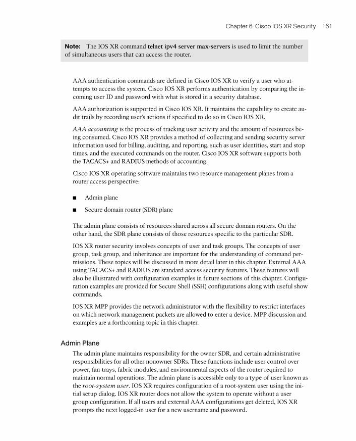
Table 6-1 Predefined User Groups
User Groups andTask Groups Purpose
cisco-support Used by Cisco Support Team. Provides access to troubleshootingcommands.
netadmin Provides the ability to control and monitor all system- and network-related parameters.
operator Provides very basic user privileges.
root-lr Provides the ability to control and monitor the specific SDR.
root-system Provides the ability to control and monitor the entire system.
sysadmin Provides the ability to control and monitor all system parametersbut cannot configure network protocols.
serviceadmin Provides the ability to administer session border controllers.
07_1587052717_ch06.qxp 5/15/09 11:21 AM Page 162
Chapter 6: Cisco IOS XR Security 163
■ W: Permits a change (or write) operation and allows an implicit read
■ E: Permits an access operation (or execution), such as ping or Telnet
■ D: Permits a debug operation
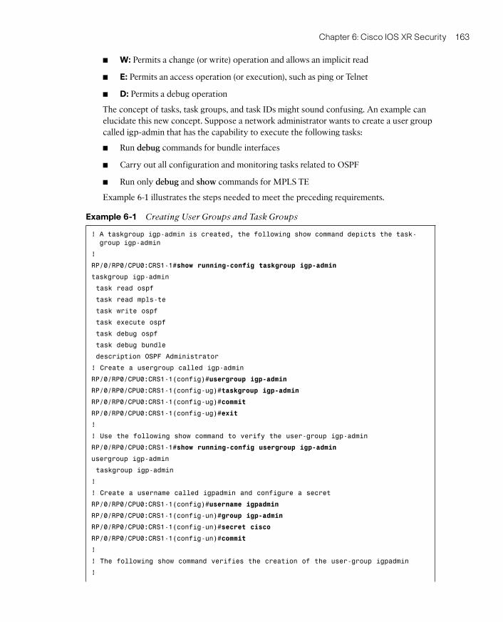
The concept of tasks, task groups, and task IDs might sound confusing. An example canelucidate this new concept. Suppose a network administrator wants to create a user groupcalled igp-admin that has the capability to execute the following tasks:
■ Run debug commands for bundle interfaces
■ Carry out all configuration and monitoring tasks related to OSPF
■ Run only debug and show commands for MPLS TE
Example 6-1 illustrates the steps needed to meet the preceding requirements.
Example 6-1 Creating User Groups and Task Groups
! A taskgroup igp-admin is created, the following show command depicts the task-
group igp-admin
!
RP/0/RP0/CPU0:CRS1-1#show running-config taskgroup igp-admin
taskgroup igp-admin
task read ospf
task read mpls-te
task write ospf
task execute ospf
task debug ospf
task debug bundle
description OSPF Administrator
! Create a usergroup called igp-admin
RP/0/RP0/CPU0:CRS1-1(config)#usergroup igp-admin
RP/0/RP0/CPU0:CRS1-1(config-ug)#taskgroup igp-admin
RP/0/RP0/CPU0:CRS1-1(config-ug)#commit
RP/0/RP0/CPU0:CRS1-1(config-ug)#exit
!
! Use the following show command to verify the user-group igp-admin
RP/0/RP0/CPU0:CRS1-1#show running-config usergroup igp-admin
usergroup igp-admin
taskgroup igp-admin
!
! Create a username called igpadmin and configure a secret
RP/0/RP0/CPU0:CRS1-1(config)#username igpadmin
RP/0/RP0/CPU0:CRS1-1(config-un)#group igp-admin
RP/0/RP0/CPU0:CRS1-1(config-un)#secret cisco
RP/0/RP0/CPU0:CRS1-1(config-un)#commit
!
! The following show command verifies the creation of the user-group igpadmin
!
07_1587052717_ch06.qxp 5/15/09 11:21 AM Page 163
164 Cisco IOS XR Fundamentals
RP/0/RP0/CPU0:CRS1-1#show running-config username igpadmin
username igpadmin
secret 5 $1$JodH$mJSA9cRx5IiISitvvOywU.
group igp-admin
!
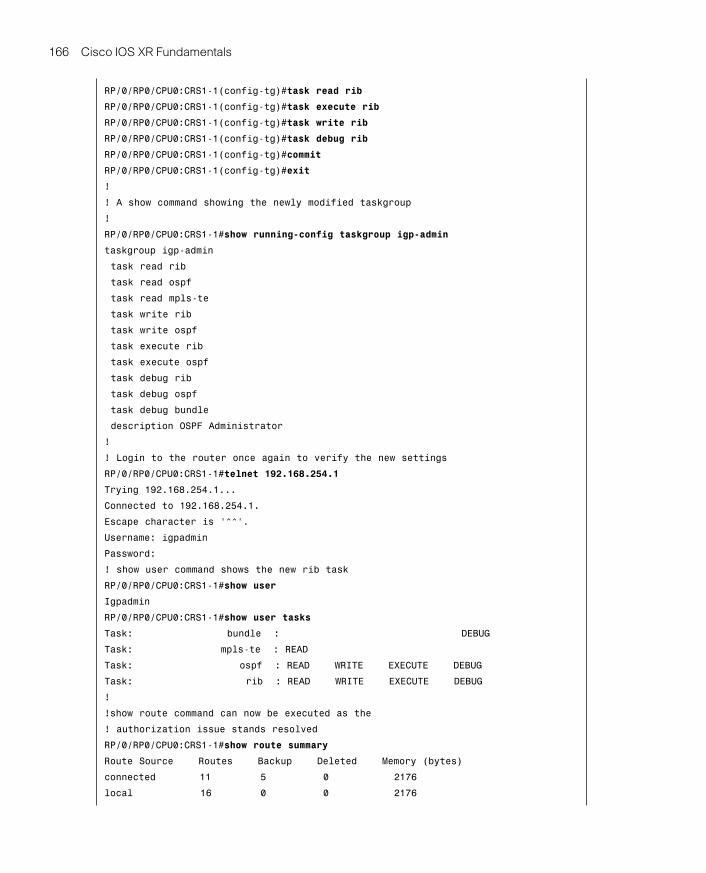
Example 6-1 creates a task group called igp-admin and assigns the task IDs READ,WRITE, EXECUTE, and DEBUG for OSPF and only READ capability for MPLS-TE andDEBUG capability for bundle tasks, respectively.
A user group called igp-admin is created that references the task group igp-admin. A localAAA username configuration is created that assigns the user group igp-admin to usernameigpadmin. The username igpadmin is configured with a secret password for authenticationpurposes. IOS XR supports both a clear text password and a one-way encrypted secret.Using the one-way encrypted secret is ideal for the application shown in Example 6-1.
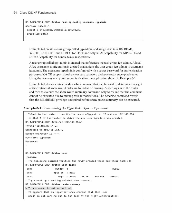
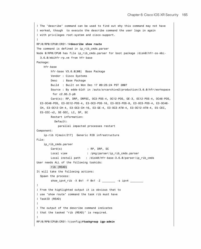
Example 6-2 demonstrates the describe command that can be used to determine the rightauthorizations if some useful tasks are found to be missing. A user logs in to the routerand tries to execute the show route summary command only to realize that the commandcannot be executed due to missing task authorizations. The describe command revealsthat the RIB (READ) privilege is required before show route summary can be executed.
Example 6-2 Determining the Right Task ID for an Operation
! Telnet to the router to verify the new configuration. IP address 192.168.254.1
is that ! of the router on which the new user igpadmin was created.
RP/0/RP0/CPU0:CRS1-1#telnet 192.168.254.1
Trying 192.168.254.1...
Connected to 192.168.254.1.
Escape character is ‘^^’.
Username: igpadmin
Password:
!
!
RP/0/RP0/CPU0:CRS1-1#show user
igpadmin
! The following command verifies the newly created tasks and their task IDs
RP/0/RP0/CPU0:CRS1-1#show user tasks
Task: bundle : DEBUG
Task: mpls-te : READ
Task: ospf : READ WRITE EXECUTE DEBUG
! Try executing a routing related show command
RP/0/RP0/CPU0:CRS1-1#show route summary
% This command is not authorized
! It appears that an important show command that this user
! needs is not working due to the lack of the right authorization.
07_1587052717_ch06.qxp 5/15/09 11:21 AM Page 164
Chapter 6: Cisco IOS XR Security 165
! The “describe” command can be used to find out why this command may not have
! worked, though to execute the describe command the user logs in again
! with privileges root-system and cisco-support.
!
RP/0/RP0/CPU0:CRS1-1#describe show route
The command is defined in ip_rib_cmds.parser
Node 0/RP0/CPU0 has file ip_rib_cmds.parser for boot package /disk0/hfr-os-mbi-
3.6.0/mbihfr-rp.vm from hfr-base
Package:
hfr-base
hfr-base V3.6.0[00] Base Package
Vendor : Cisco Systems
Desc : Base Package
Build : Built on Mon Dec 17 09:25:24 PST 2007
Source : By edde-bld1 in /auto/srcarchive2/production/3.6.0/hfr/workspace
for c2.95.3-p8
Card(s): RP, DRP, DRPSC, OC3-POS-4, OC12-POS, GE-3, OC12-POS-4, OC48-POS,
E3-OC48-POS, E3-OC12-POS-4, E3-OC3-POS-16, E3-OC3-POS-8, E3-OC3-POS-4, E3-OC48-
CH, E3-OC12-CH-4, E3-OC3-CH-16, E3-GE-4, E3-OC3-ATM-4, E3-OC12-ATM-4, E5-CEC,
E5-CEC-v2, SE-SEC, LC, SP, SC
Restart information:
Default:
parallel impacted processes restart
Component:
ip-rib V[main/217] Generic RIB infrastructure
File:
ip_rib_cmds.parser
Card(s) : RP, DRP, SC
Local view : /pkg/parser/ip_rib_cmds.parser
Local install path : /disk0/hfr-base-3.6.0/parser/ip_rib_cmds
User needs ALL of the following taskids:
rib (READ)
It will take the following actions:
Spawn the process:
show_ipv4_rib -X 0x1 -Y 0x1 -Z ________ -s ipv4 ________
!
! From the highlighted output it is obvious that to
! use “show route” command the task rib must have
! TaskID (READ)
!
! The output of the describe command indicates
! that the tasked “rib (READ)” is required.
!
RP/0/RP0/CPU0:CRS1-1(config)#taskgroup igp-admin
07_1587052717_ch06.qxp 5/15/09 11:21 AM Page 165
166 Cisco IOS XR Fundamentals
RP/0/RP0/CPU0:CRS1-1(config-tg)#task read rib
RP/0/RP0/CPU0:CRS1-1(config-tg)#task execute rib
RP/0/RP0/CPU0:CRS1-1(config-tg)#task write rib
RP/0/RP0/CPU0:CRS1-1(config-tg)#task debug rib
RP/0/RP0/CPU0:CRS1-1(config-tg)#commit
RP/0/RP0/CPU0:CRS1-1(config-tg)#exit
!
! A show command showing the newly modified taskgroup
!
RP/0/RP0/CPU0:CRS1-1#show running-config taskgroup igp-admin
taskgroup igp-admin
task read rib
task read ospf
task read mpls-te
task write rib
task write ospf
task execute rib
task execute ospf
task debug rib
task debug ospf
task debug bundle
description OSPF Administrator
!
! Login to the router once again to verify the new settings
RP/0/RP0/CPU0:CRS1-1#telnet 192.168.254.1
Trying 192.168.254.1...
Connected to 192.168.254.1.
Escape character is ‘^^’.
Username: igpadmin
Password:
! show user command shows the new rib task
RP/0/RP0/CPU0:CRS1-1#show user
Igpadmin
RP/0/RP0/CPU0:CRS1-1#show user tasks
Task: bundle : DEBUG
Task: mpls-te : READ
Task: ospf : READ WRITE EXECUTE DEBUG
Task: rib : READ WRITE EXECUTE DEBUG
!
!show route command can now be executed as the
! authorization issue stands resolved
RP/0/RP0/CPU0:CRS1-1#show route summary
Route Source Routes Backup Deleted Memory (bytes)
connected 11 5 0 2176
local 16 0 0 2176
07_1587052717_ch06.qxp 5/15/09 11:21 AM Page 166
Chapter 6: Cisco IOS XR Security 167
ospf 1 5 0 0 680
isis xr 4 4 0 1216
static 2 0 0 272
bgp 102 0 0 0 0
local SMIAP 1 0 0 136
Total 39 9 0 6656
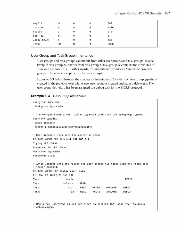
User Group and Task Group Inheritance
User groups and task groups can inherit from other user groups and task groups, respec-tively. If task group X inherits from task group Y, task group X contains the attributes ofX as well as those of Y. In other words, this inheritance produces a “union” of two taskgroups. The same concept is true for user groups.
Example 6-3 helps illustrate the concept of inheritance. Consider the user group igpadmincreated in the previous example. A new user group is created and named deb-eigrp. Theuser group deb-eigrp has been assigned the debug task for the EIGRP protocol.
Example 6-3 User Group Inheritance
usergroup igpadmin
taskgroup igp-admin
! The example shows a user called igpadmin that uses the usergroup igpadmin
username igpadmin
group igpadmin
secret 5 $1$laNp$2s/dTtBkqvfkB01B9wqft/
! User igpadmin logs into the router as shown:
RP/0/RP1/CPU0:CRS-1#telnet 192.168.0.1
Trying 192.168.0.1...
Connected to 192.168.0.1.
Username: igpadmin
Password: cisco
! After logging into the router the user checks his tasks with the “show user
! tasks” command.
RP/0/RP1/CPU0:CRS-1#show user tasks
Fri Mar 20 10:26:01.356 PST
Task: bundle : DEBUG
Task: mpls-te : READ
Task: ospf : READ WRITE EXECUTE DEBUG
Task: rib : READ WRITE EXECUTE DEBUG
! Now a new usergroup called deb-eigrp is created that uses the taskgroup
! debug-eigrp.
07_1587052717_ch06.qxp 5/15/09 11:21 AM Page 167
168 Cisco IOS XR Fundamentals
! This configuration is carried out the network administrator and not the
! igpadmin user.
RP/0/RP1/CPU0:CRS-1#show run taskgroup debug-eigrp
Fri Mar 20 10:31:44.150 PST
taskgroup debug-eigrp
task debug eigrp
!
usergroup deb-eigrp
taskgroup debug-eigrp
!
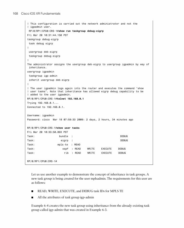
The administrator assigns the usergroup deb-eigrp to usergroup igpadmin by way of
inheritance.
usergroup igpadmin
taskgroup igp-admin
inherit usergroup deb-eigrp
!
! The user igpadmin logs again into the router and executes the command “show
! user tasks”. Note that inheritance has allowed eigrp debug capability to be
! added to the user igpadmin.
RP/0/RP1/CPU0:CRS-1#telnet 192.168.0.1
Trying 192.168.0.1...
Connected to 192.168.0.1.
Username: igpadmin
Password: cisco Mar 18 07:59:33 2009: 2 days, 2 hours, 34 minutes ago
RP/0/RP1/CPU0:CRS-1#show user tasks
Fri Mar 20 10:33:50.893 PST
Task: bundle : DEBUG
Task: eigrp : DEBUG
Task: mpls-te : READ
Task: ospf : READ WRITE EXECUTE DEBUG
Task: rib : READ WRITE EXECUTE DEBUG
RP/0/RP1/CPU0:CRS-1#
Let us use another example to demonstrate the concept of inheritance in task groups. Anew task group is being created for the user mplsadmin. The requirements for this user areas follows:
■ READ, WRITE, EXECUTE, and DEBUG task IDs for MPLS TE
■ All the attributes of task group igp-admin
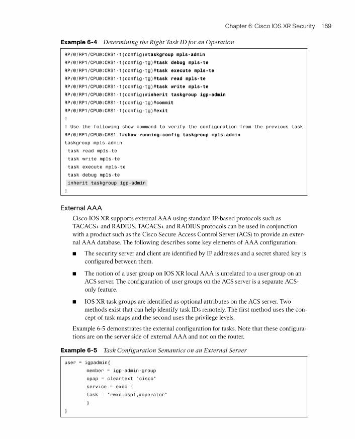
Example 6-4 creates the new task group using inheritance from the already existing taskgroup called igp-admin that was created in Example 6-3.
07_1587052717_ch06.qxp 5/15/09 11:21 AM Page 168
Chapter 6: Cisco IOS XR Security 169
Example 6-4 Determining the Right Task ID for an Operation
RP/0/RP1/CPU0:CRS1-1(config)#taskgroup mpls-admin
RP/0/RP1/CPU0:CRS1-1(config-tg)#task debug mpls-te
RP/0/RP1/CPU0:CRS1-1(config-tg)#task execute mpls-te
RP/0/RP1/CPU0:CRS1-1(config-tg)#task read mpls-te
RP/0/RP1/CPU0:CRS1-1(config-tg)#task write mpls-te
RP/0/RP1/CPU0:CRS1-1(config)#inherit taskgroup igp-admin
RP/0/RP1/CPU0:CRS1-1(config-tg)#commit
RP/0/RP1/CPU0:CRS1-1(config-tg)#exit
!
! Use the following show command to verify the configuration from the previous task
RP/0/RP1/CPU0:CRS1-1#show running-config taskgroup mpls-admin
taskgroup mpls-admin
task read mpls-te
task write mpls-te
task execute mpls-te
task debug mpls-te
inherit taskgroup igp-admin
!
External AAA
Cisco IOS XR supports external AAA using standard IP-based protocols such asTACACS+ and RADIUS. TACACS+ and RADIUS protocols can be used in conjunctionwith a product such as the Cisco Secure Access Control Server (ACS) to provide an exter-nal AAA database. The following describes some key elements of AAA configuration:
■ The security server and client are identified by IP addresses and a secret shared key isconfigured between them.
■ The notion of a user group on IOS XR local AAA is unrelated to a user group on anACS server. The configuration of user groups on the ACS server is a separate ACS-only feature.
■ IOS XR task groups are identified as optional attributes on the ACS server. Twomethods exist that can help identify task IDs remotely. The first method uses the con-cept of task maps and the second uses the privilege levels.
Example 6-5 demonstrates the external configuration for tasks. Note that these configura-tions are on the server side of external AAA and not on the router.
Example 6-5 Task Configuration Semantics on an External Server
user = igpadmin{
member = igp-admin-group
opap = cleartext “cisco”
service = exec {
task = “rwxd:ospf,#operator”
}
}
07_1587052717_ch06.qxp 5/15/09 11:21 AM Page 169
170 Cisco IOS XR Fundamentals
Example 6-5 specifies the task ID as an attribute in the external TACACS+ or RADIUSserver. Note that this is shown as an example only. Because the procedure can vary fromserver to server, consult the TACACS+ or RADIUS server documentation to find out howyou can use the optional attributes. A freeware TACACS+ server from Cisco might requirean asterisk (*) instead of an equal sign (=) before the attribute value for optional attributes.Example 6-5 shows the task string in the configuration file of the TACACS+ server wheretokens are delimited by a comma (,). Each token contains either a task ID name or its per-missions in the following format:
task = “<permissions>:<taskid name>, #<usergroup name>, ...” .
In Example 6-5, the task = “rwxd:ospf,#operator” assigns READ, WRITE, EXECUTE, andDEBUG task IDs to the OSPF task and assigns the user group operator.
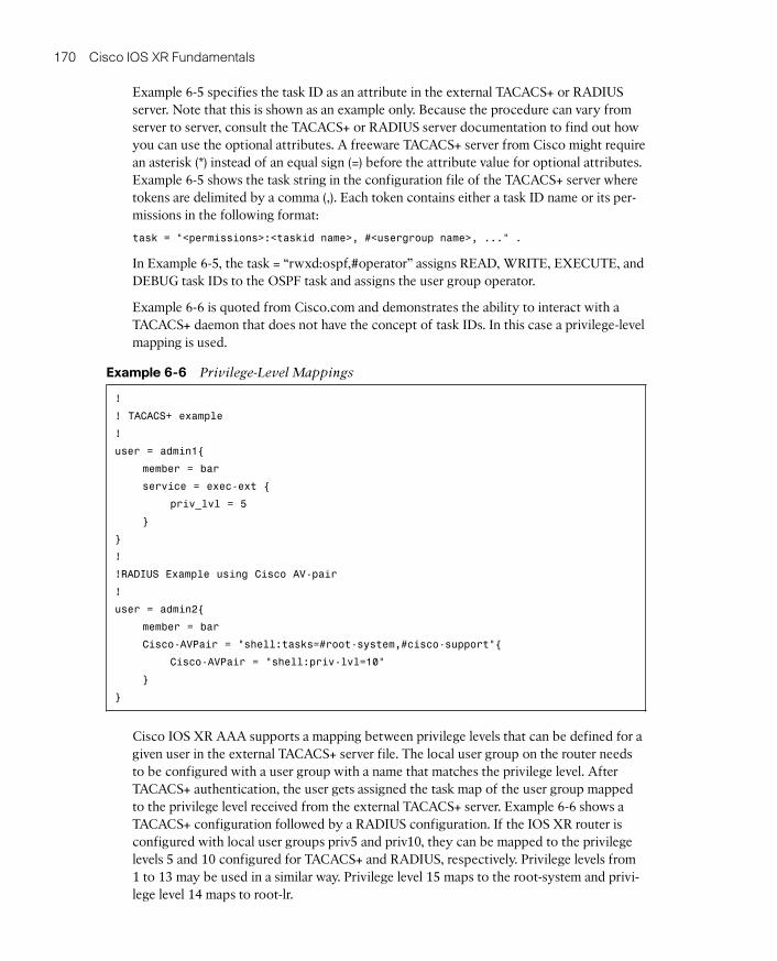
Example 6-6 is quoted from Cisco.com and demonstrates the ability to interact with aTACACS+ daemon that does not have the concept of task IDs. In this case a privilege-levelmapping is used.
Example 6-6 Privilege-Level Mappings
!
! TACACS+ example
!
user = admin1{
member = bar
service = exec-ext {
priv_lvl = 5
}
}
!
!RADIUS Example using Cisco AV-pair
!
user = admin2{
member = bar
Cisco-AVPair = “shell:tasks=#root-system,#cisco-support”{
Cisco-AVPair = “shell:priv-lvl=10”
}
}
Cisco IOS XR AAA supports a mapping between privilege levels that can be defined for agiven user in the external TACACS+ server file. The local user group on the router needsto be configured with a user group with a name that matches the privilege level. AfterTACACS+ authentication, the user gets assigned the task map of the user group mappedto the privilege level received from the external TACACS+ server. Example 6-6 shows aTACACS+ configuration followed by a RADIUS configuration. If the IOS XR router isconfigured with local user groups priv5 and priv10, they can be mapped to the privilegelevels 5 and 10 configured for TACACS+ and RADIUS, respectively. Privilege levels from1 to 13 may be used in a similar way. Privilege level 15 maps to the root-system and privi-lege level 14 maps to root-lr.
07_1587052717_ch06.qxp 5/15/09 11:21 AM Page 170
Chapter 6: Cisco IOS XR Security 171
The following sections discuss the configuration behind external AAA. Various CLI com-mand options for configuring TACACS+ are presented.
Configuring a TACACS+ Server
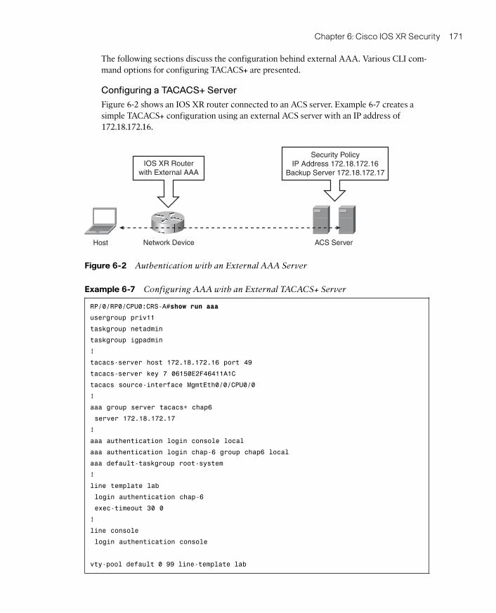
Figure 6-2 shows an IOS XR router connected to an ACS server. Example 6-7 creates asimple TACACS+ configuration using an external ACS server with an IP address of172.18.172.16.
Example 6-7 Configuring AAA with an External TACACS+ Server
RP/0/RP0/CPU0:CRS-A#show run aaa
usergroup priv11
taskgroup netadmin
taskgroup igpadmin
!
tacacs-server host 172.18.172.16 port 49
tacacs-server key 7 06150E2F46411A1C
tacacs source-interface MgmtEth0/0/CPU0/0
!
aaa group server tacacs+ chap6
server 172.18.172.17
!
aaa authentication login console local
aaa authentication login chap-6 group chap6 local
aaa default-taskgroup root-system
!
line template lab
login authentication chap-6
exec-timeout 30 0
!
line console
login authentication console
vty-pool default 0 99 line-template lab
ACS ServerHost Network Device
IOS XR Routerwith External AAA
Security PolicyIP Address 172.18.172.16
Backup Server 172.18.172.17
Figure 6-2 Authentication with an External AAA Server
07_1587052717_ch06.qxp 5/15/09 11:21 AM Page 171
172 Cisco IOS XR Fundamentals
In Example 6-7, a privilege 11 configuration exists on the ACS server. The AAA server isidentified with the tacacs server host command and a backup server is identified with theaaa group server command. The local keyword in the aaa authentication login chap-6group chap6 local command ensures that AAA will authenticate locally in the case offailure of both the ACS servers. The AAA method list chap-6 gets assigned to the vtypool.
Authentication Using RADIUS
This section shows some configuration examples for AAA RADIUS client configurationon IOS XR to allow authentication with an external ACS server.
Example 6-8 shows a basic AAA RADIUS configuration. The basic concept is the same asthat shown in Example 6-7 except the TACACS+ protocol has been replaced by RADIUS.
Example 6-8 Configuring AAA with an External RADIUS Server
RP/0/RP0/CPU0:CRS-B_IOX#show run aaa
usergroup priv13
taskgroup root-system
taskgroup cisco-support
!
radius-server host 172.18.172.16
key 7 104D000A0618
!
radius source-interface MgmtEth0/RP0/CPU0/0
aaa authentication login telnet group radius local
aaa authentication login default local
!
line template rads
login authentication telnet
exec-timeout 0 0
session-timeout 0
vty-pool default 0 99 line-template rads
telnet ipv4 server max-servers no-limit
Example 6-9 shows AAA RADIUS authentication and introduces a new authorizationcommand: aaa authorization exec default none. This command has the same effect as thekeyword if-authenticated in IOS AAA authorization commands. The configuration statesthat if a user is authenticated, that user is also authorized.
Example 6-9 AAA with an External RADIUS Server with Accounting andAuthorization
! Configures Radius server dead times and dead-criteria
!
radius-server deadtime 1
radius-server dead-criteria time 15
radius-server dead-criteria tries 2
07_1587052717_ch06.qxp 5/15/09 11:21 AM Page 172
Chapter 6: Cisco IOS XR Security 173
!
! Configures the RADIUS server hosts
!
aaa group server radius XR-GROUP
server 172.18.172.16 auth-port 1645 acct-port 1646
server 172.18.172.17 auth-port 1645 acct-port 1646
!
! Enables AAA accounting
aaa accounting exec default start-stop group XR-GROUP
aaa accounting commands default start-stop group XR-GROUP
!
! Configure authorization to occur automatically if the user gets authenticated
!
aaa authorization exec default none
!
! sets login authentication to use the default method list and XR-GROUP server
aaa authentication login default group XR-GROUP local
end
Configuring Secure Shell
Secure Shell (SSH) is a useful protocol or application for establishing secure sessions withthe router. A router configured with SSH server allows a secure connection to the routersimilar to Telnet. The Telnet application has limited security. SSH provides stronger en-cryption and deploys public-key cryptography for added confidentiality. SFTP also comesas a component of SSH and enables secure FTP (SFTP) capabilities for downloading soft-ware or configuration files. IOS XR supports two versions of SSH:
■ SSH version 1 uses Rivest, Shamire, and Adelman (RSA) keys.
■ SSH version 2 uses the Digital Signature Algorithm (DSA).
Enabling SSH on IOS XR requires the Hfr-k9sec security PIE to be installed on the router.In addition to installing the k9sec PIE, IOS XR requires RSA or DSA keys to be generatedon the router before SSH runs in server mode. Example 6-10 illustrates the SSH configura-tion on IOS XR.
Example 6-10 Enabling SSH v2 on IOS XR
!
!The command below verifies the existence of k9sec pie
!
RP/0/RP1/CPU0:CRS1-1(admin)#show install active | include k9sec
disk0:hfr-k9sec-3.6.0
!
! The following command generates DSA key pairs
!
RP/0/RP1/CPU0:CRS1-1#crypto key generate dsa
07_1587052717_ch06.qxp 5/15/09 11:21 AM Page 173
174 Cisco IOS XR Fundamentals
The name for the keys will be: the_default
Choose the size of your DSA key modulus. Modulus size can be 512, 768, or 1024
bits. Choosing a key modulus
How many bits in the modulus [1024]: 1024
Generating DSA keys ...
Done w/ crypto generate keypair
[OK]
!
RP/0/RP1/CPU0:CRS1-1(config)#ssh server v2
RP/0/RP1/CPU0:CRS1-1(config)#commit
In Example 6-10 the presence of the k9sec PIE is verified first. If this PIE is not present, itneeds to be installed. The example shows the generation of DSA keys by executing thecrypto key generate dsa command, followed by enabling SSH version 2 in Configurationmode.
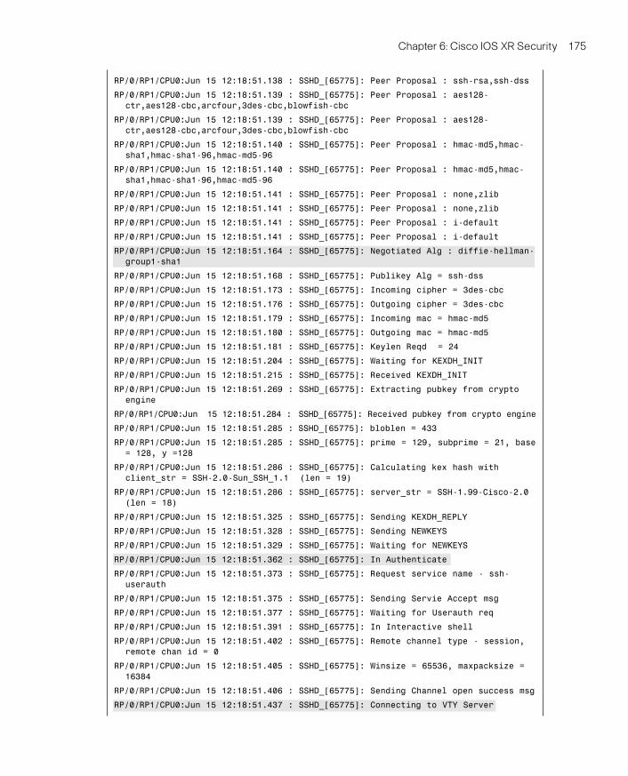
Example 6-11 demonstrates the debugging of SSH server functionality on a router withthe debug ssh server command followed by the show ssh session detail command.
Example 6-11 Debugging SSH v2 on IOS XR
! Enable ssh server debugging on the router
!
RP/0/RP1/CPU0:CRS1-1#debug ssh server
RP/0/RP1/CPU0:CRS1-1#show debug
#### debug flags set from tty ‘vty0’ ####
ssh server flag is ON
!
! Create an SSH session from a unix server to the IOS XR router
!
$ ssh [email protected]
Password:cisco
Last switch-over Sun Jun 1 08:51:09 2008: 2 weeks, 3 hours, 27 minutes ago
RP/0/RP1/CPU0:CRS1-1#RP/0/RP1/CPU0:Jun 15 12:18:50.284 : SSHD_[364]: Spawned new
child process 6852847
RP/0/RP1/CPU0:Jun 15 12:18:50.482 : SSHD_[65775]: Client sockfd 3
RP/0/RP1/CPU0:Jun 15 12:18:50.494 : SSHD_[65775]: Connection from 10.10.20.100
port 61532
RP/0/RP1/CPU0:Jun 15 12:18:50.517 : SSHD_[65775]: Session id 0
RP/0/RP1/CPU0:Jun 15 12:18:50.521 : SSHD_[65775]: Exchanging versions
RP/0/RP1/CPU0:Jun 15 12:18:50.539 : SSHD_[65775]: Remote protocol version 2.0,
remote software version Sun_SSH_1.1
RP/0/RP1/CPU0:Jun 15 12:18:50.540 : SSHD_[65775]: In Key exchange
RP/0/RP1/CPU0:Jun 15 12:18:51.137 : SSHD_[65775]: Received ———————> KEXINIT
RP/0/RP1/CPU0:Jun 15 12:18:51.137 : SSHD_[65775]: Calling Receive kexinit 10
RP/0/RP1/CPU0:Jun 15 12:18:51.137 : SSHD_[65775]: Peer Proposal : diffie-hellman-
group-exchange-sha1,diffie-hellman-group1-sha1
07_1587052717_ch06.qxp 5/15/09 11:21 AM Page 174
Chapter 6: Cisco IOS XR Security 175
RP/0/RP1/CPU0:Jun 15 12:18:51.138 : SSHD_[65775]: Peer Proposal : ssh-rsa,ssh-dss
RP/0/RP1/CPU0:Jun 15 12:18:51.139 : SSHD_[65775]: Peer Proposal : aes128-
ctr,aes128-cbc,arcfour,3des-cbc,blowfish-cbc
RP/0/RP1/CPU0:Jun 15 12:18:51.139 : SSHD_[65775]: Peer Proposal : aes128-
ctr,aes128-cbc,arcfour,3des-cbc,blowfish-cbc
RP/0/RP1/CPU0:Jun 15 12:18:51.140 : SSHD_[65775]: Peer Proposal : hmac-md5,hmac-
sha1,hmac-sha1-96,hmac-md5-96
RP/0/RP1/CPU0:Jun 15 12:18:51.140 : SSHD_[65775]: Peer Proposal : hmac-md5,hmac-
sha1,hmac-sha1-96,hmac-md5-96
RP/0/RP1/CPU0:Jun 15 12:18:51.141 : SSHD_[65775]: Peer Proposal : none,zlib
RP/0/RP1/CPU0:Jun 15 12:18:51.141 : SSHD_[65775]: Peer Proposal : none,zlib
RP/0/RP1/CPU0:Jun 15 12:18:51.141 : SSHD_[65775]: Peer Proposal : i-default
RP/0/RP1/CPU0:Jun 15 12:18:51.141 : SSHD_[65775]: Peer Proposal : i-default
RP/0/RP1/CPU0:Jun 15 12:18:51.164 : SSHD_[65775]: Negotiated Alg : diffie-hellman-
group1-sha1
RP/0/RP1/CPU0:Jun 15 12:18:51.168 : SSHD_[65775]: Publikey Alg = ssh-dss
RP/0/RP1/CPU0:Jun 15 12:18:51.173 : SSHD_[65775]: Incoming cipher = 3des-cbc
RP/0/RP1/CPU0:Jun 15 12:18:51.176 : SSHD_[65775]: Outgoing cipher = 3des-cbc
RP/0/RP1/CPU0:Jun 15 12:18:51.179 : SSHD_[65775]: Incoming mac = hmac-md5
RP/0/RP1/CPU0:Jun 15 12:18:51.180 : SSHD_[65775]: Outgoing mac = hmac-md5
RP/0/RP1/CPU0:Jun 15 12:18:51.181 : SSHD_[65775]: Keylen Reqd = 24
RP/0/RP1/CPU0:Jun 15 12:18:51.204 : SSHD_[65775]: Waiting for KEXDH_INIT
RP/0/RP1/CPU0:Jun 15 12:18:51.215 : SSHD_[65775]: Received KEXDH_INIT
RP/0/RP1/CPU0:Jun 15 12:18:51.269 : SSHD_[65775]: Extracting pubkey from crypto
engine
RP/0/RP1/CPU0:Jun 15 12:18:51.284 : SSHD_[65775]: Received pubkey from crypto engine
RP/0/RP1/CPU0:Jun 15 12:18:51.285 : SSHD_[65775]: bloblen = 433
RP/0/RP1/CPU0:Jun 15 12:18:51.285 : SSHD_[65775]: prime = 129, subprime = 21, base
= 128, y =128
RP/0/RP1/CPU0:Jun 15 12:18:51.286 : SSHD_[65775]: Calculating kex hash with
client_str = SSH-2.0-Sun_SSH_1.1 (len = 19)
RP/0/RP1/CPU0:Jun 15 12:18:51.286 : SSHD_[65775]: server_str = SSH-1.99-Cisco-2.0
(len = 18)
RP/0/RP1/CPU0:Jun 15 12:18:51.325 : SSHD_[65775]: Sending KEXDH_REPLY
RP/0/RP1/CPU0:Jun 15 12:18:51.328 : SSHD_[65775]: Sending NEWKEYS
RP/0/RP1/CPU0:Jun 15 12:18:51.329 : SSHD_[65775]: Waiting for NEWKEYS
RP/0/RP1/CPU0:Jun 15 12:18:51.362 : SSHD_[65775]: In Authenticate
RP/0/RP1/CPU0:Jun 15 12:18:51.373 : SSHD_[65775]: Request service name - ssh-
userauth
RP/0/RP1/CPU0:Jun 15 12:18:51.375 : SSHD_[65775]: Sending Servie Accept msg
RP/0/RP1/CPU0:Jun 15 12:18:51.377 : SSHD_[65775]: Waiting for Userauth req
RP/0/RP1/CPU0:Jun 15 12:18:51.391 : SSHD_[65775]: In Interactive shell
RP/0/RP1/CPU0:Jun 15 12:18:51.402 : SSHD_[65775]: Remote channel type - session,
remote chan id = 0
RP/0/RP1/CPU0:Jun 15 12:18:51.405 : SSHD_[65775]: Winsize = 65536, maxpacksize =
16384
RP/0/RP1/CPU0:Jun 15 12:18:51.406 : SSHD_[65775]: Sending Channel open success msg
RP/0/RP1/CPU0:Jun 15 12:18:51.437 : SSHD_[65775]: Connecting to VTY Server
07_1587052717_ch06.qxp 5/15/09 11:21 AM Page 175
176 Cisco IOS XR Fundamentals
RP/0/RP1/CPU0:Jun 15 12:18:51.494 : SSHD_[65775]: Opening file /dev/vty9999
RP/0/RP1/CPU0:Jun 15 12:18:51.496 : SSHD_[65775]: Allocated pty vty1.
RP/0/RP1/CPU0:Jun 15 12:18:51.497 : SSHD_[65775]: Setting window size row = 24,
col = 106
RP/0/RP1/CPU0:Jun 15 12:18:51.615 : SSHD_[65775]: Spawned shell
RP/0/RP1/CPU0:Jun 15 12:18:51.677 : SSHD_[65775]: event_contex_init done
!
! Show command to verify the SSH session detail on the router.
!
RP/0/RP1/CPU0:CRS1-1#show ssh session details
SSH version : Cisco-2.0
id key-exchange pubkey incipher outcipher inmac outmac
—————————————————————————————————-
Incoming Session
diffie-hellman ssh-dss 3des-cbc 3des-cbc hmac-md5 hmac-md5
! A command output showing the incoming SSH TCP session
!
RP/0/RP1/CPU0:CRS1-1#show tcp brief
PCB VRF-ID Recv-Q Send-Q Local Address Foreign Address State
0x482e2c30 0x60000000 0 0 :::22 :::0 LISTEN
0x482e2ea0 0x60000001 0 0 :::22 :::0 LISTEN
0x482e8248 0x00000000 0 0 :::22 :::0 LISTEN
0x482e5a38 0x60000000 0 0 10.0.0.11:646 10.0.0.31:35777 ESTAB
0x482cc0a8 0x60000000 0 0 10.0.0.11:646 10.0.0.21:57878 ESTAB
0x482deff4 0x60000000 0 0 10.10.20.31:23 10.10.20.100:61512 ESTAB
0x482e7714 0x60000000 0 0 10.10.20.31:22 10.10.20.100:61532 ESTAB
0x482e8380 0x60000000 0 0 0.0.0.0:22 0.0.0.0:0 LISTEN
0x482e2d68 0x60000001 0 0 0.0.0.0:22 0.0.0.0:0 LISTEN
0x482e8598 0x00000000 0 0 0.0.0.0:22 0.0.0.0:0 LISTEN
0x482d0660 0x60000000 0 0 0.0.0.0:23 0.0.0.0:0 LISTEN
0x482e0dc4 0x00000000 0 0 0.0.0.0:23 0.0.0.0:0 LISTEN
0x482cf2e4 0x60000000 0 0 0.0.0.0:639 0.0.0.0:0 LISTEN
0x482cd9e4 0x60000000 0 0 0.0.0.0:646 0.0.0.0:0 LISTEN
07_1587052717_ch06.qxp 5/15/09 11:21 AM Page 176
Chapter 6: Cisco IOS XR Security 177
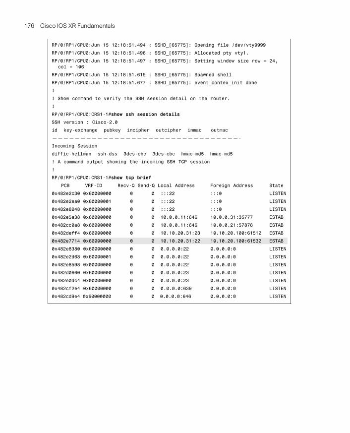
Example 6-11 shows an SSH session created from a UNIX host to the router and the cor-responding debug output produced on the console. The debug output shows the exchang-ing of SSH version between the UNIX host and the router as well as the negotiation of theDiffie-Hellman key exchange. The example also presents the show ssh session detail com-mand’s output showing the details of the SSH session. The output of show tcp briefshows the TCP port 22 sessions that identifies the incoming SSH connection.
Management Plane Protection
Management plane refers to a router’s architectural components involved in the process-ing of traffic that is meant for the management of the routing platform. ManagementPlane Protection (MPP) is a relatively new feature in IOS XR; it was introduced in Release3.5.0. It helps control the interfaces on which network management traffic can enter therouter. The capability helps enhance the router-level security and allows the network ad-ministrator better granularity in controlling management access to the router.
Following are the salient features of MPP:
■ Enhances the manageability and security aspects of IOS XR.
■ Helps alleviate the need to configure more access lists in controlling router access.
■ Management ports on RP and DRP are not configurable under MPP because they areout of band by default.
■ Controls incoming traffic for protocols, such as TFTP, Telnet, Simple Network Man-agement Protocol (SNMP), SSH, and HTTP.
■ Allows control for both in-band and out-of-band interfaces.
■ Can specify a peer IPv4 or IPv6 address or subnet from which traffic is allowed, thusproviding more control.
In the context of MPP, an in-band management interface is an interface that receives andprocesses management packets as well as forwards Internet traffic. This interface may alsobe referred to as a shared management interface. An out-of-band interface allows onlymanagement protocol traffic to be forwarded or processed. This type of interface doesnot process or receive any customer or Internet traffic and, therefore, has lower potentialfor becoming a victim of a DoS attack. Out-of-band interfaces are usually also the last hopinterfaces in the life of a packet, and these packets are then processed by higher-layer pro-tocols on the router.
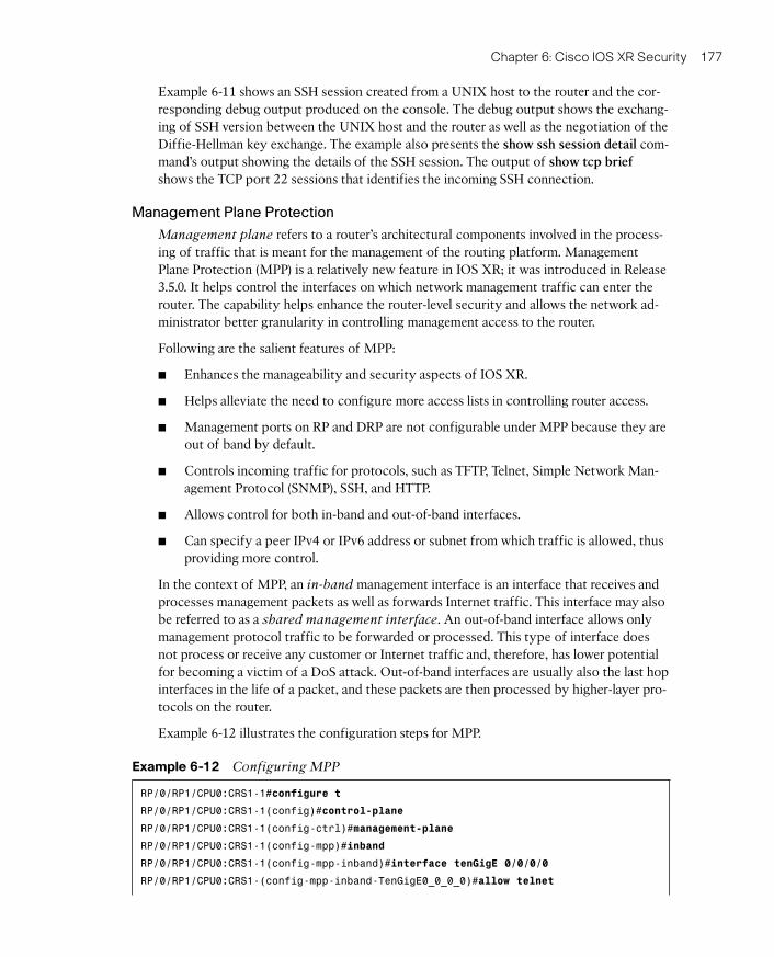
Example 6-12 illustrates the configuration steps for MPP.
Example 6-12 Configuring MPP
RP/0/RP1/CPU0:CRS1-1#configure t
RP/0/RP1/CPU0:CRS1-1(config)#control-plane
RP/0/RP1/CPU0:CRS1-1(config-ctrl)#management-plane
RP/0/RP1/CPU0:CRS1-1(config-mpp)#inband
RP/0/RP1/CPU0:CRS1-1(config-mpp-inband)#interface tenGigE 0/0/0/0
RP/0/RP1/CPU0:CRS1-(config-mpp-inband-TenGigE0_0_0_0)#allow telnet
07_1587052717_ch06.qxp 5/15/09 11:21 AM Page 177
178 Cisco IOS XR Fundamentals
RP/0/RP1/CPU0:CRS1-(config-mpp-inband-TenGigE0_0_0_0)#commit
RP/0/RP1/CPU0:CRS1-(config-mpp-inband-TenGigE0_0_0_0)#exit
RP/0/RP1/CPU0:CRS1-1(config-mpp-inband)#exit
RP/0/RP1/CPU0:CRS1-1(config-mpp)#out-of-band
RP/0/RP1/CPU0:CRS1-1(config-mpp-outband)#vrf red
RP/0/RP1/CPU0:CRS1-1(config-mpp-outband)#interface tenGigE 0/0/0/0.1
RP/0/RP1/CPU0:CR(config-mpp-outband-TenGigE0_0_0_0.1)#allow snmp
RP/0/RP1/CPU0:CR(config-mpp-outband-TenGigE0_0_0_0.1)#allow telnet
RP/0/RP1/CPU0:CR(config-mpp-outband-TenGigE0_0_0_0.1)#commit
RP/0/RP1/CPU0:CR(config-mpp-outband-TenGigE0_0_0_0.1)#
! Using an MPP show command
RP/0/RP1/CPU0:CRS1-1#show mgmt-plane
Management Plane Protection
inband interfaces
———————————
interface - TenGigE0_0_0_0
telnet configured -
All peers allowed
outband interfaces
———————————
interface - TenGigE0_0_0_0.1
telnet configured -
All peers allowed
snmp configured -
All peers allowed
RP/0/RP1/CPU0:CRS1-1#
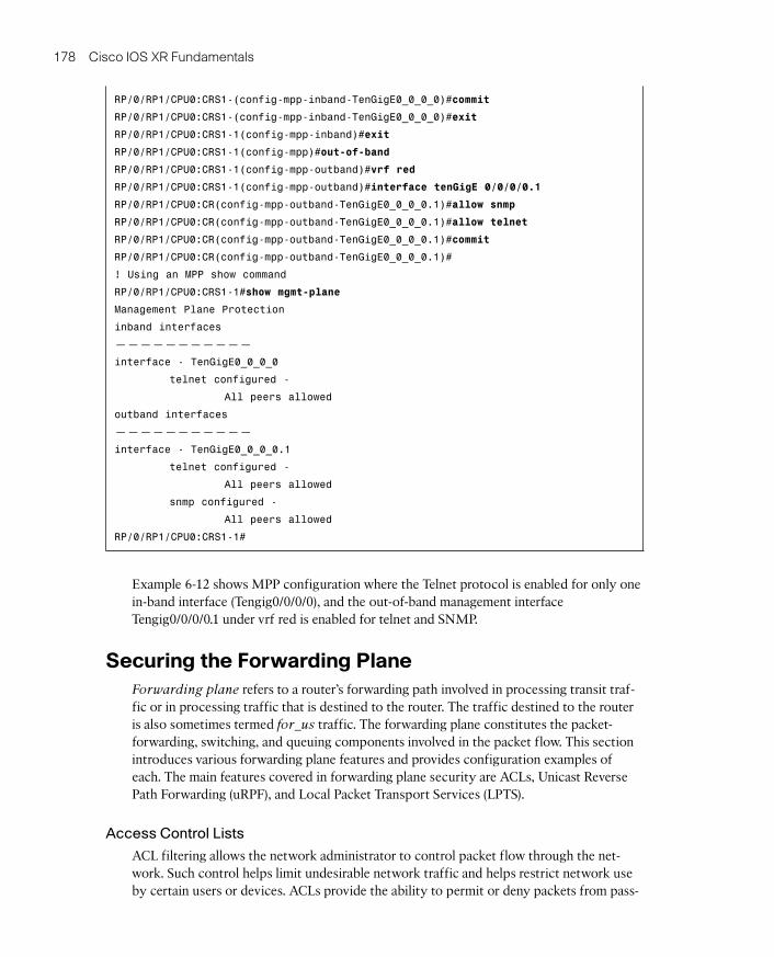
Example 6-12 shows MPP configuration where the Telnet protocol is enabled for only onein-band interface (Tengig0/0/0/0), and the out-of-band management interfaceTengig0/0/0/0.1 under vrf red is enabled for telnet and SNMP.
Securing the Forwarding PlaneForwarding plane refers to a router’s forwarding path involved in processing transit traf-fic or in processing traffic that is destined to the router. The traffic destined to the routeris also sometimes termed for_us traffic. The forwarding plane constitutes the packet-forwarding, switching, and queuing components involved in the packet flow. This sectionintroduces various forwarding plane features and provides configuration examples ofeach. The main features covered in forwarding plane security are ACLs, Unicast ReversePath Forwarding (uRPF), and Local Packet Transport Services (LPTS).
Access Control Lists
ACL filtering allows the network administrator to control packet flow through the net-work. Such control helps limit undesirable network traffic and helps restrict network useby certain users or devices. ACLs provide the ability to permit or deny packets from pass-
07_1587052717_ch06.qxp 5/15/09 11:21 AM Page 178
Chapter 6: Cisco IOS XR Security 179
ing through specific router interfaces. Access lists also find several uses in providing gran-ularity and control to control plane protocols.
Following are some of the key features of IOS XR access lists:
■ Named access lists: Cisco IOS XR uses named access lists only. Internally, the ac-cess list is treated as a string or name. IOS XR uses only named access lists. Even if anumber is used to denote an access list, it is internally treated as a string or a name.
■ Standard or Extended Keywords: IOS XR does not use standard and extendedkeywords in specifying an access list. An access list can include mixed Access Con-trol Elements (ACE) that use only source-based filtering or both source- and destination-based filtering that may be combined with protocol port operations.
■ Locally originated traffic: Cisco IOS XR egress ACLs do not filter traffic origi-nated by the router.
■ ACL numbering and resequence: Cisco IOS XR ACLs use line numbering to helpreplace a particular line in an ACL definition. An option is provided to resequence theACL line numberings if required.
■ Remarks: Cisco IOS XR ACLs provide the ability to insert remarks in an access listto help explain the purpose of the particular line in an ACL.
■ Log messages: Cisco IOS XR provides the ability to log an ACL. Logging an ACLproduces a syslog message when a packet matches a line with the log keyword. Thisoperation is CPU intensive and must not be enabled for high speed traffic rates. Usu-ally an ACL with a log keyword can be used for ACLs applied to vty lines. A log key-word may also be used for temporary debugging purposes, keeping in mind that itsuse is CPU intensive.
■ ICMP unreachables: IOS XR ACL deny packet operation on an interface producesa rate-controlled ICMP unreachable message. This ICMP message can be disabledfrom the interface by using the CLI no ipv4 unreachables.
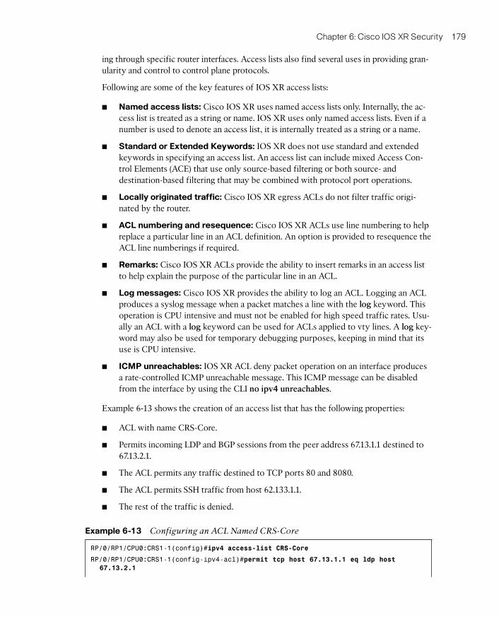
Example 6-13 shows the creation of an access list that has the following properties:
■ ACL with name CRS-Core.
■ Permits incoming LDP and BGP sessions from the peer address 67.13.1.1 destined to67.13.2.1.
■ The ACL permits any traffic destined to TCP ports 80 and 8080.
■ The ACL permits SSH traffic from host 62.133.1.1.
■ The rest of the traffic is denied.
Example 6-13 Configuring an ACL Named CRS-Core
RP/0/RP1/CPU0:CRS1-1(config)#ipv4 access-list CRS-Core
RP/0/RP1/CPU0:CRS1-1(config-ipv4-acl)#permit tcp host 67.13.1.1 eq ldp host
67.13.2.1
07_1587052717_ch06.qxp 5/15/09 11:21 AM Page 179
180 Cisco IOS XR Fundamentals
RP/0/RP1/CPU0:CRS1-1(config-ipv4-acl)#permit tcp host 67.13.1.1 host 67.13.2.1 eq
ldp
RP/0/RP1/CPU0:CRS1-1(config-ipv4-acl)#permit tcp host 67.13.1.1 host 67.13.2.1 eq
bgp
RP/0/RP1/CPU0:CRS1-1(config-ipv4-acl)#permit tcp any eq 80 any
RP/0/RP1/CPU0:CRS1-1(config-ipv4-acl)#permit tcp any any eq 80
RP/0/RP1/CPU0:CRS1-1(config-ipv4-acl)#permit tcp any eq 8080 any
RP/0/RP1/CPU0:CRS1-1(config-ipv4-acl)#permit tcp any any eq 8080
RP/0/RP1/CPU0:CRS1-1(config-ipv4-acl)#permit tcp host 62.133.1.1 any eq 22
RP/0/RP1/CPU0:CRS1-1(config-ipv4-acl)#permit icmp 65.10.20.0 0.0.0.255 any echo
RP/0/RP1/CPU0:CRS1-1(config-ipv4-acl)#permit icmp 65.10.20.0 0.0.0.255 any echo-
reply
RP/0/RP1/CPU0:CRS1-1(config-ipv4-acl)#commit
RP/0/RP1/CPU0:CRS1-1(config-ipv4-acl)#exit
RP/0/RP1/CPU0:CRS1-1(config)#
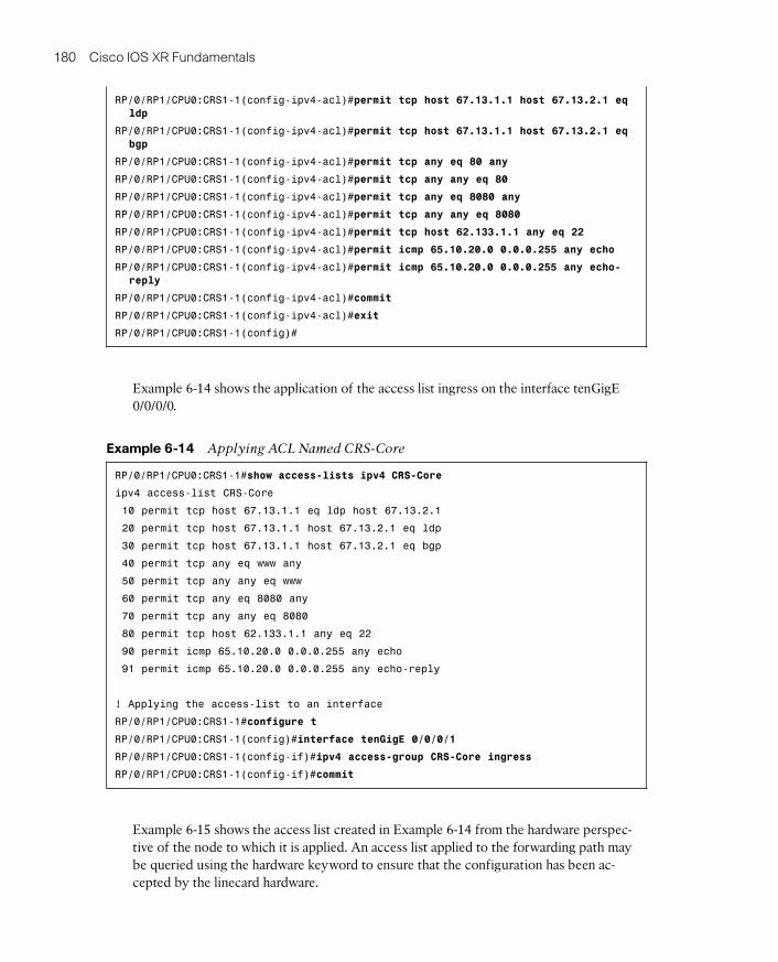
Example 6-14 shows the application of the access list ingress on the interface tenGigE0/0/0/0.
Example 6-14 Applying ACL Named CRS-Core
RP/0/RP1/CPU0:CRS1-1#show access-lists ipv4 CRS-Core
ipv4 access-list CRS-Core
10 permit tcp host 67.13.1.1 eq ldp host 67.13.2.1
20 permit tcp host 67.13.1.1 host 67.13.2.1 eq ldp
30 permit tcp host 67.13.1.1 host 67.13.2.1 eq bgp
40 permit tcp any eq www any
50 permit tcp any any eq www
60 permit tcp any eq 8080 any
70 permit tcp any any eq 8080
80 permit tcp host 62.133.1.1 any eq 22
90 permit icmp 65.10.20.0 0.0.0.255 any echo
91 permit icmp 65.10.20.0 0.0.0.255 any echo-reply
! Applying the access-list to an interface
RP/0/RP1/CPU0:CRS1-1#configure t
RP/0/RP1/CPU0:CRS1-1(config)#interface tenGigE 0/0/0/1
RP/0/RP1/CPU0:CRS1-1(config-if)#ipv4 access-group CRS-Core ingress
RP/0/RP1/CPU0:CRS1-1(config-if)#commit
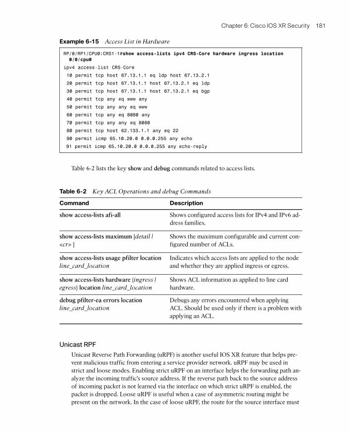
Example 6-15 shows the access list created in Example 6-14 from the hardware perspec-tive of the node to which it is applied. An access list applied to the forwarding path maybe queried using the hardware keyword to ensure that the configuration has been ac-cepted by the linecard hardware.
07_1587052717_ch06.qxp 5/15/09 11:21 AM Page 180
Chapter 6: Cisco IOS XR Security 181
Example 6-15 Access List in Hardware
RP/0/RP1/CPU0:CRS1-1#show access-lists ipv4 CRS-Core hardware ingress location
0/0/cpu0
ipv4 access-list CRS-Core
10 permit tcp host 67.13.1.1 eq ldp host 67.13.2.1
20 permit tcp host 67.13.1.1 host 67.13.2.1 eq ldp
30 permit tcp host 67.13.1.1 host 67.13.2.1 eq bgp
40 permit tcp any eq www any
50 permit tcp any any eq www
60 permit tcp any eq 8080 any
70 permit tcp any any eq 8080
80 permit tcp host 62.133.1.1 any eq 22
90 permit icmp 65.10.20.0 0.0.0.255 any echo
91 permit icmp 65.10.20.0 0.0.0.255 any echo-reply
Table 6-2 lists the key show and debug commands related to access lists.
Unicast RPF
Unicast Reverse Path Forwarding (uRPF) is another useful IOS XR feature that helps pre-vent malicious traffic from entering a service provider network. uRPF may be used instrict and loose modes. Enabling strict uRPF on an interface helps the forwarding path an-alyze the incoming traffic’s source address. If the reverse path back to the source addressof incoming packet is not learned via the interface on which strict uRPF is enabled, thepacket is dropped. Loose uRPF is useful when a case of asymmetric routing might bepresent on the network. In the case of loose uRPF, the route for the source interface must
Table 6-2 Key ACL Operations and debug Commands
Command Description
show access-lists afi-all Shows configured access lists for IPv4 and IPv6 ad-dress families.
show access-lists maximum [detail |
<cr> ]Shows the maximum configurable and current con-figured number of ACLs.
show access-lists usage pfilter locationline_card_location
Indicates which access lists are applied to the nodeand whether they are applied ingress or egress.
show access-lists hardware {ingress |
egress} location line_card_location
Shows ACL information as applied to line cardhardware.
debug pfilter-ea errors locationline_card_location
Debugs any errors encountered when applyingACL. Should be used only if there is a problem withapplying an ACL.
07_1587052717_ch06.qxp 5/15/09 11:21 AM Page 181
182 Cisco IOS XR Fundamentals
be in the routing table. Configuration options may also allow default routes to satisfyloose uRPF requirements.
The following command configures strict or loose uRPF at the interface level:
{ipv4 | ipv6} verify unicast source reachable-via {any | rx} [allow-default]
[allow-self-ping]
The explanation of this command follows:
■ Using the any option after verify unicast source reachable-via enables loose uRPF.
■ Using the rx option after verify unicast source reachable-via enables strict uRPF.
■ The allow-default option allows uRPF check to be true against a default route. Thisoption is equally applicable to loose and strict uRPF.
■ The allow-self-ping option allows the router to ping itself and is applicable to bothloose and strict uRPF.
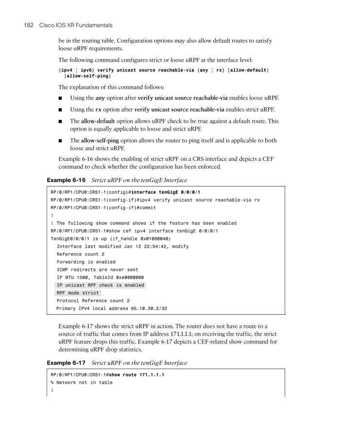
Example 6-16 shows the enabling of strict uRPF on a CRS interface and depicts a CEFcommand to check whether the configuration has been enforced.
Example 6-16 Strict uRPF on the tenGigE Interface
RP/0/RP1/CPU0:CRS1-1(config)#interface tenGigE 0/0/0/1
RP/0/RP1/CPU0:CRS1-1(config-if)#ipv4 verify unicast source reachable-via rx
RP/0/RP1/CPU0:CRS1-1(config-if)#commit
!
! The following show command shows if the feature has been enabled
RP/0/RP1/CPU0:CRS1-1#show cef ipv4 interface tenGigE 0/0/0/1
TenGigE0/0/0/1 is up (if_handle 0x01080040)
Interface last modified Jan 12 22:54:42, modify
Reference count 2
Forwarding is enabled
ICMP redirects are never sent
IP MTU 1500, TableId 0xe0000000
IP unicast RPF check is enabled
RPF mode strict
Protocol Reference count 2
Primary IPV4 local address 65.10.20.2/32
Example 6-17 shows the strict uRPF in action. The router does not have a route to asource of traffic that comes from IP address 171.1.1.1; on receiving the traffic, the strictuRPF feature drops this traffic. Example 6-17 depicts a CEF-related show command fordetermining uRPF drop statistics.
Example 6-17 Strict uRPF on the tenGigE Interface
RP/0/RP1/CPU0:CRS1-1#show route 171.1.1.1
% Network not in table
!
07_1587052717_ch06.qxp 5/15/09 11:21 AM Page 182
Chapter 6: Cisco IOS XR Security 183
! shows RPF statistics
RP/0/RP1/CPU0:CRS1-1#show cef ipv4 interface tenGigE 0/0/0/1 rpf-statistics
Unicast RPF drops 1000
Local Packet Transport Service
The forwarding plane security section has so far discussed features such as ACLs anduRPF, which filter packets based on certain criteria. This section discusses Local PacketTransport Service (LPTS). LPTS provides software architecture to deliver locally destinedtraffic to the correct node on the router and provides security against overwhelming therouter resources with excessive traffic. LPTS achieves security by policing flows of locallydestined traffic to a value that can be easily sustained by the CPU capabilities of the plat-form.
The first question you might ask is what sort of traffic constitutes locally destined traffic.Although routers are in the business of forwarding packets, there are scenarios in whichthe traffic may be locally destined, including the following:
■ All IPv4, IPv6, and MPLS traffic related to routing protocols, or control plane such asMPLS LDP or RSVP. The control plane computations for protocols are done on theRouter Processor (RP) of the router. Therefore, whenever routing or MPLS controlplane traffic is received on a line card interface, it needs to be delivered to the RP ofthe router.
■ MPLS packets with the Router Alert label
■ IPv4, IPv6, or MPLS packets with a TTL less than 2
■ IPv4 or IPv6 packets with options
■ IP packets requiring fragmentation or reassembly
■ Layer 2 keepalives
■ Address Resolution Protocol (ARP) packets
■ ICMP message generation and response
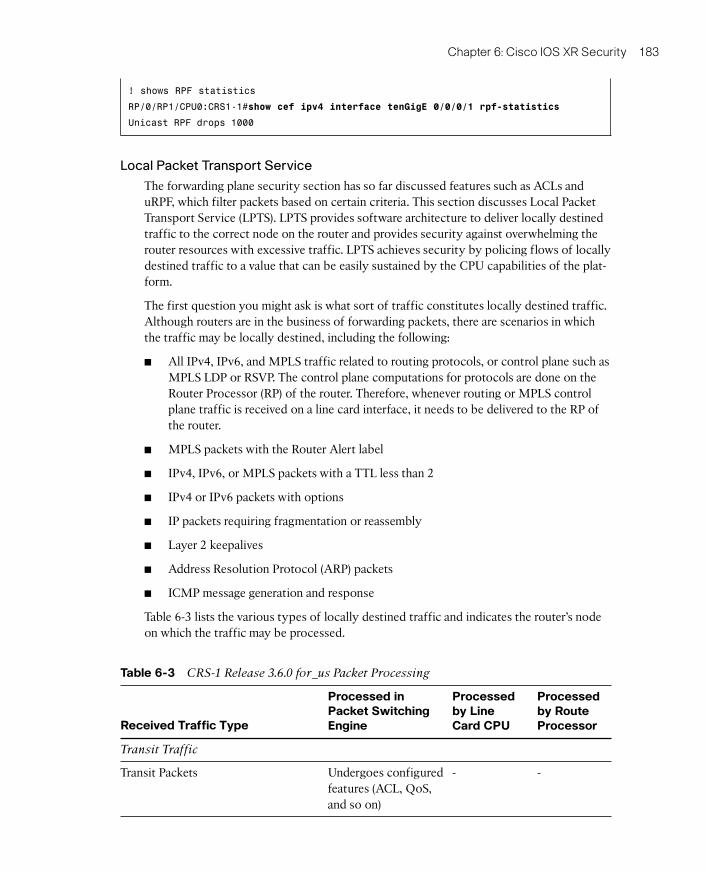
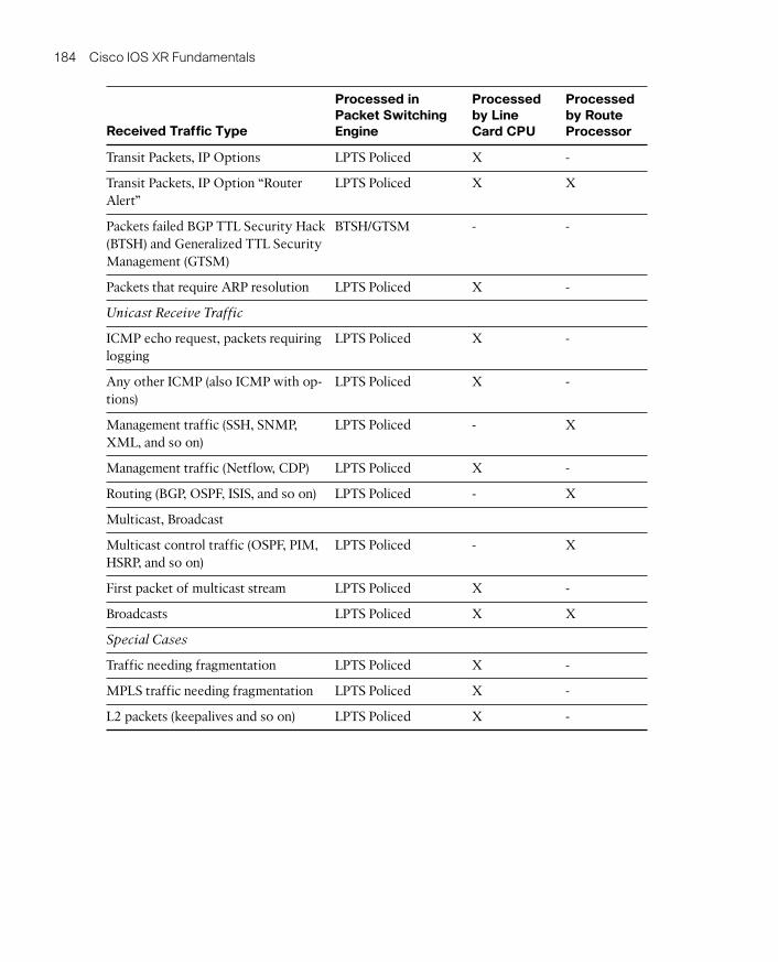
Table 6-3 lists the various types of locally destined traffic and indicates the router’s nodeon which the traffic may be processed.
Table 6-3 CRS-1 Release 3.6.0 for_us Packet Processing
Received Traffic Type
Processed inPacket SwitchingEngine
Processedby LineCard CPU
Processedby RouteProcessor
Transit Traffic
Transit Packets Undergoes configuredfeatures (ACL, QoS,and so on)
- -
07_1587052717_ch06.qxp 5/15/09 11:21 AM Page 183
184 Cisco IOS XR Fundamentals
Received Traffic Type
Processed inPacket SwitchingEngine
Processedby LineCard CPU
Processedby RouteProcessor
Transit Packets, IP Options LPTS Policed X -
Transit Packets, IP Option “RouterAlert”
LPTS Policed X X
Packets failed BGP TTL Security Hack(BTSH) and Generalized TTL SecurityManagement (GTSM)
BTSH/GTSM - -
Packets that require ARP resolution LPTS Policed X -
Unicast Receive Traffic
ICMP echo request, packets requiringlogging
LPTS Policed X -
Any other ICMP (also ICMP with op-tions)
LPTS Policed X -
Management traffic (SSH, SNMP,XML, and so on)
LPTS Policed - X
Management traffic (Netflow, CDP) LPTS Policed X -
Routing (BGP, OSPF, ISIS, and so on) LPTS Policed - X
Multicast, Broadcast
Multicast control traffic (OSPF, PIM,HSRP, and so on)
LPTS Policed - X
First packet of multicast stream LPTS Policed X -
Broadcasts LPTS Policed X X
Special Cases
Traffic needing fragmentation LPTS Policed X -
MPLS traffic needing fragmentation LPTS Policed X -
L2 packets (keepalives and so on) LPTS Policed X -
07_1587052717_ch06.qxp 5/15/09 11:21 AM Page 184
Chapter 6: Cisco IOS XR Security 185
LPTS provides sort of a built-in firewall for an IOS XR router by taking preemptive meas-ures for traffic flows destined to the router. The forthcoming discussions explain howLPTS provides its protection mechanisms.
Mechanics Behind LPTS: A High-Level Overview
Cisco IOS XR runs on platforms with a distributed architecture. Distributed architectureimplies that the control plane and the forwarding planes are decoupled for meeting higherrouting and forwarding performance objectives. As Table 6-3 in the preceding sectionshows, an IOS XR router might need to deliver different types of for_us packets to differ-ent nodes within the router. Additionally, IOS XR supports process placement on CRS-1platforms using Distributed Route Processors (DRP). Therefore, a line card receiving acontrol plane packet needs to make complex decisions regarding the node to which apacket might need to be delivered, keeping in mind that the router may be using a DRP fordistributing a control plane process. Furthermore, nonstop routing (NSR) features mightrequire a control packet be replicated both to an active and a standby RP.
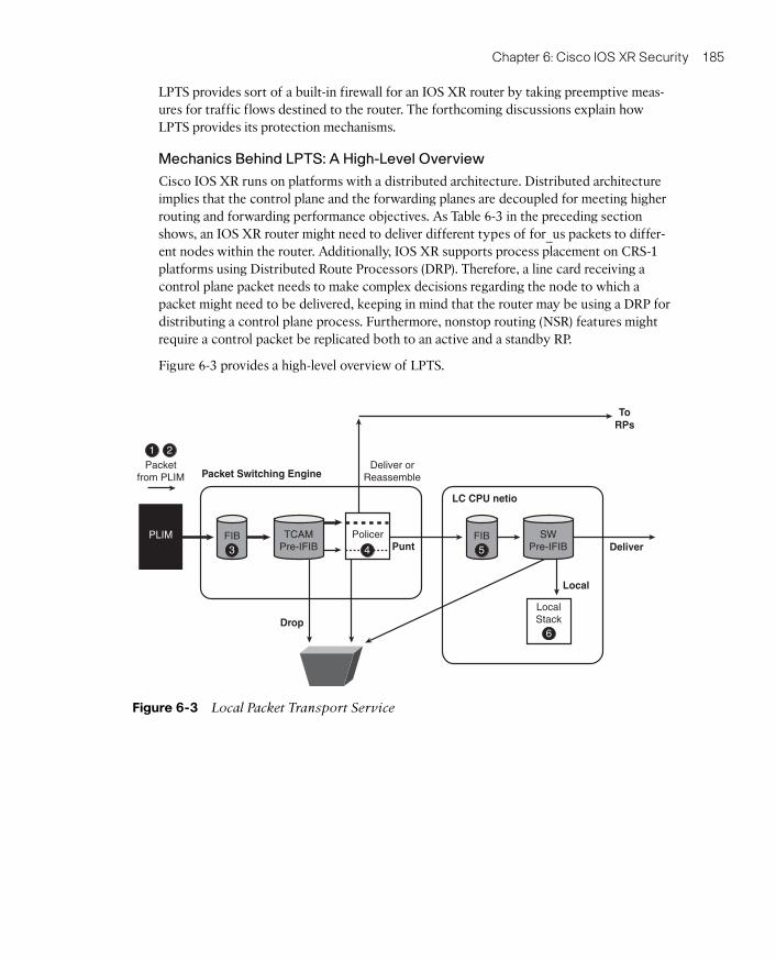
Figure 6-3 provides a high-level overview of LPTS.
PLIM
Packet Switching Engine
LC CPU netio
Drop
Punt Deliver
Local
ToRPs
1 2
6
FIB
Packetfrom PLIM
Deliver orReassemble
TCAMPre-IFIB
FIB SWPre-IFIB
Policer
LocalStack
3 4 5
Figure 6-3 Local Packet Transport Service
07_1587052717_ch06.qxp 5/15/09 11:21 AM Page 185
186 Cisco IOS XR Fundamentals
The process follows:
1. On a CRS-1 router, the Physical layer Interface Module (PLIM) receives the frame.
2. On receiving the packet and performing the necessary layer 1 and 2 checks, the PLIMextracts the layer 3 packet and passes it to the forwarding ASIC or the Packet Switch-
ing Engine (PSE) as it is commonly called.
3. The L3 forwarding engine does a Forwarding Information Base (FIB) lookup and de-termines whether the packet is a locally destined for_us packet.
4. The LPTS infrastructure maintains tables in the line card’s TCAM and also on the RPfor handling the for_us packets. The table on the RP is a detailed list of all possibleflows of traffic types that can be destined to the router. The detailed table on RP iscalled the IFIB. A smaller table that is a subset of IFIB exists on the line card and thistable is referred to as the pIFIB. The pIFIB lists flows of critical traffic. These tablesare populated by a set of processes known as a LPTS Port Arbitrator (lpts_pa) andLPTS flow manager (lpts_fm). A process called pifibm_server runs on the line cardand is responsible for programming hardware for the policing values for differentflows. To qualify for a match in the pIFIB, the incoming packet must exactly matchthe pIFIB table entry in a single lookup.
5. Consider a packet that arrives on a line card and a pIFIB lookup returns a full match.The packet then gets assigned a Fabric Group Identifier (FGID) allocated by thelpts_pa process. FGID serves as an identifier that helps a packet traverse the paththrough the various ASICs on the switch fabric to be delivered to FabricQ asic on thedestination node from where the packet finds its way to the primary/standby RP,DRP, or the line card CPU. The destination node could also be an RP, a DRP, or theline card CPU of the line card on which the packet was received. In case a line cardpIFIB entry results in a partial match the incoming packet is referred to the IFIB main-tained on the RP.
6. The CPU on the RP, DRP, and line card run the software processes that decapsulatethe packet and deliver them to the correct stack.
The discussion related to Figure 6-3 gives a simplified overview of LPTS mostly from thepoint of view of local packet delivery. However, a key feature of LPTS includes policingthe locally destined flows to values deemed safe for CPU resources.
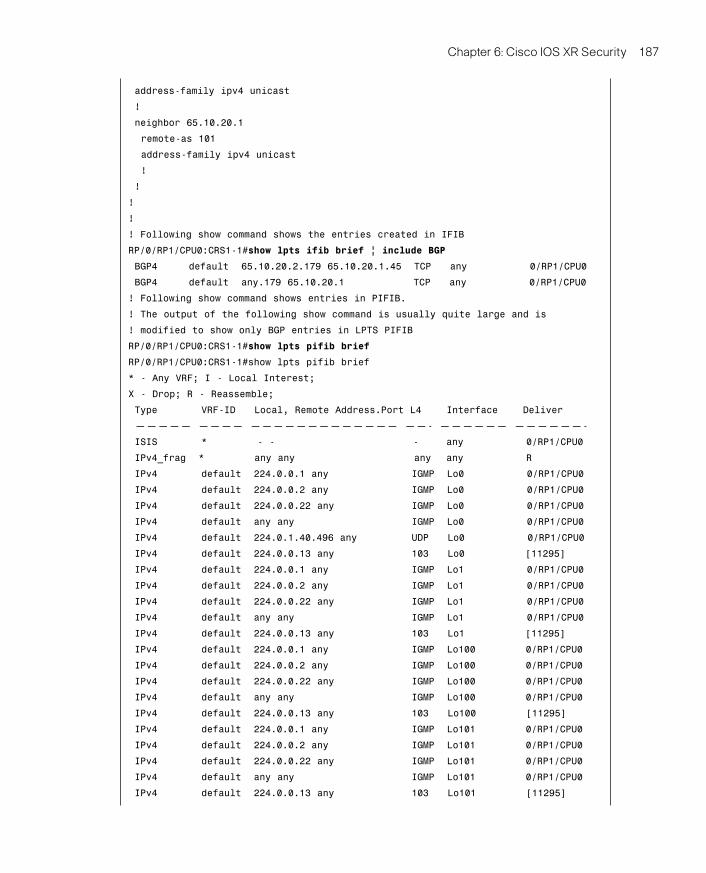
Consider Example 6-18, which shows the LPTS entries accompanying a BGP configura-tion.
Example 6-18 BGP Entries in LPTS
! show command indicating the committed BGP configuration
!
RP/0/RP1/CPU0:CRS1-1#show running-config router bgp
router bgp 102
bgp router-id 192.168.254.1
07_1587052717_ch06.qxp 5/15/09 11:21 AM Page 186
Chapter 6: Cisco IOS XR Security 187
address-family ipv4 unicast
!
neighbor 65.10.20.1
remote-as 101
address-family ipv4 unicast
!
!
!
!
! Following show command shows the entries created in IFIB
RP/0/RP1/CPU0:CRS1-1#show lpts ifib brief | include BGP
BGP4 default 65.10.20.2.179 65.10.20.1.45 TCP any 0/RP1/CPU0
BGP4 default any.179 65.10.20.1 TCP any 0/RP1/CPU0
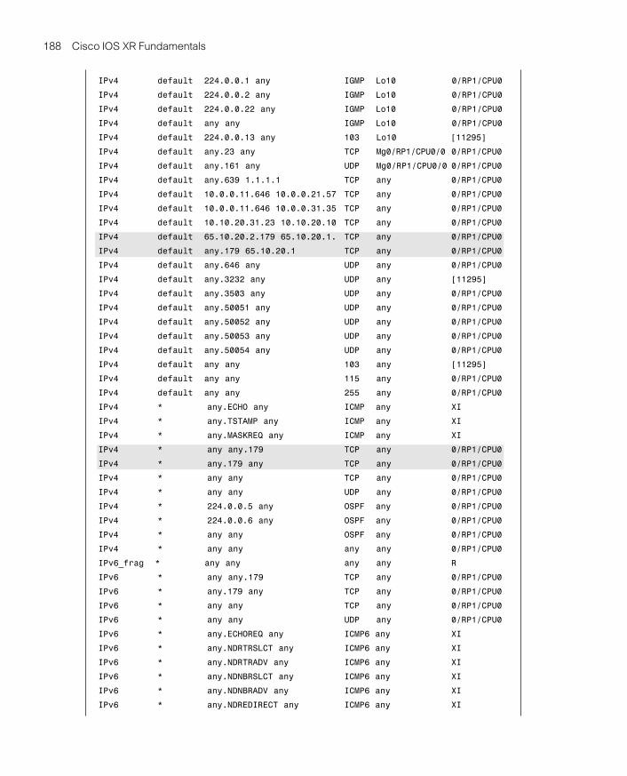
! Following show command shows entries in PIFIB.
! The output of the following show command is usually quite large and is
! modified to show only BGP entries in LPTS PIFIB
RP/0/RP1/CPU0:CRS1-1#show lpts pifib brief
RP/0/RP1/CPU0:CRS1-1#show lpts pifib brief
* - Any VRF; I - Local Interest;
X - Drop; R - Reassemble;
Type VRF-ID Local, Remote Address.Port L4 Interface Deliver
————— ———— ————————————— ——- —————— ——————-
ISIS * - - - any 0/RP1/CPU0
IPv4_frag * any any any any R
IPv4 default 224.0.0.1 any IGMP Lo0 0/RP1/CPU0
IPv4 default 224.0.0.2 any IGMP Lo0 0/RP1/CPU0
IPv4 default 224.0.0.22 any IGMP Lo0 0/RP1/CPU0
IPv4 default any any IGMP Lo0 0/RP1/CPU0
IPv4 default 224.0.1.40.496 any UDP Lo0 0/RP1/CPU0
IPv4 default 224.0.0.13 any 103 Lo0 [11295]
IPv4 default 224.0.0.1 any IGMP Lo1 0/RP1/CPU0
IPv4 default 224.0.0.2 any IGMP Lo1 0/RP1/CPU0
IPv4 default 224.0.0.22 any IGMP Lo1 0/RP1/CPU0
IPv4 default any any IGMP Lo1 0/RP1/CPU0
IPv4 default 224.0.0.13 any 103 Lo1 [11295]
IPv4 default 224.0.0.1 any IGMP Lo100 0/RP1/CPU0
IPv4 default 224.0.0.2 any IGMP Lo100 0/RP1/CPU0
IPv4 default 224.0.0.22 any IGMP Lo100 0/RP1/CPU0
IPv4 default any any IGMP Lo100 0/RP1/CPU0
IPv4 default 224.0.0.13 any 103 Lo100 [11295]
IPv4 default 224.0.0.1 any IGMP Lo101 0/RP1/CPU0
IPv4 default 224.0.0.2 any IGMP Lo101 0/RP1/CPU0
IPv4 default 224.0.0.22 any IGMP Lo101 0/RP1/CPU0
IPv4 default any any IGMP Lo101 0/RP1/CPU0
IPv4 default 224.0.0.13 any 103 Lo101 [11295]
07_1587052717_ch06.qxp 5/15/09 11:21 AM Page 187
188 Cisco IOS XR Fundamentals
IPv4 default 224.0.0.1 any IGMP Lo10 0/RP1/CPU0
IPv4 default 224.0.0.2 any IGMP Lo10 0/RP1/CPU0
IPv4 default 224.0.0.22 any IGMP Lo10 0/RP1/CPU0
IPv4 default any any IGMP Lo10 0/RP1/CPU0
IPv4 default 224.0.0.13 any 103 Lo10 [11295]
IPv4 default any.23 any TCP Mg0/RP1/CPU0/0 0/RP1/CPU0
IPv4 default any.161 any UDP Mg0/RP1/CPU0/0 0/RP1/CPU0
IPv4 default any.639 1.1.1.1 TCP any 0/RP1/CPU0
IPv4 default 10.0.0.11.646 10.0.0.21.57 TCP any 0/RP1/CPU0
IPv4 default 10.0.0.11.646 10.0.0.31.35 TCP any 0/RP1/CPU0
IPv4 default 10.10.20.31.23 10.10.20.10 TCP any 0/RP1/CPU0
IPv4 default 65.10.20.2.179 65.10.20.1. TCP any 0/RP1/CPU0
IPv4 default any.179 65.10.20.1 TCP any 0/RP1/CPU0
IPv4 default any.646 any UDP any 0/RP1/CPU0
IPv4 default any.3232 any UDP any [11295]
IPv4 default any.3503 any UDP any 0/RP1/CPU0
IPv4 default any.50051 any UDP any 0/RP1/CPU0
IPv4 default any.50052 any UDP any 0/RP1/CPU0
IPv4 default any.50053 any UDP any 0/RP1/CPU0
IPv4 default any.50054 any UDP any 0/RP1/CPU0
IPv4 default any any 103 any [11295]
IPv4 default any any 115 any 0/RP1/CPU0
IPv4 default any any 255 any 0/RP1/CPU0
IPv4 * any.ECHO any ICMP any XI
IPv4 * any.TSTAMP any ICMP any XI
IPv4 * any.MASKREQ any ICMP any XI
IPv4 * any any.179 TCP any 0/RP1/CPU0
IPv4 * any.179 any TCP any 0/RP1/CPU0
IPv4 * any any TCP any 0/RP1/CPU0
IPv4 * any any UDP any 0/RP1/CPU0
IPv4 * 224.0.0.5 any OSPF any 0/RP1/CPU0
IPv4 * 224.0.0.6 any OSPF any 0/RP1/CPU0
IPv4 * any any OSPF any 0/RP1/CPU0
IPv4 * any any any any 0/RP1/CPU0
IPv6_frag * any any any any R
IPv6 * any any.179 TCP any 0/RP1/CPU0
IPv6 * any.179 any TCP any 0/RP1/CPU0
IPv6 * any any TCP any 0/RP1/CPU0
IPv6 * any any UDP any 0/RP1/CPU0
IPv6 * any.ECHOREQ any ICMP6 any XI
IPv6 * any.NDRTRSLCT any ICMP6 any XI
IPv6 * any.NDRTRADV any ICMP6 any XI
IPv6 * any.NDNBRSLCT any ICMP6 any XI
IPv6 * any.NDNBRADV any ICMP6 any XI
IPv6 * any.NDREDIRECT any ICMP6 any XI
07_1587052717_ch06.qxp 5/15/09 11:21 AM Page 188
Chapter 6: Cisco IOS XR Security 189
IPv6 * ff02::5 any OSPF any 0/RP1/CPU0
IPv6 * ff02::6 any OSPF any 0/RP1/CPU0
IPv6 * any any OSPF any 0/RP1/CPU0
IPv6 * any any any any 0/RP1/CPU0
RP/0/RP1/CPU0:CRS1-1#! Hardware Policing values in pifib
!
RP/0/RP1/CPU0:CRS1-1#show lpts pifib hardware police location 0/0/cpu0
——————————————————————————————-
Node 0/0/CPU0:
——————————————————————————————-
Burst = 100ms for all flow types
——————————————————————————————-
FlowType Policer Type Cur. Rate Def. Rate Accepted Dropped
——————————— ———- ———- ————— ————— ————— —————
unconfigured-default 100 Static 500 500 0 0
Fragment 106 Static 1000 1000 0 0
OSPF-mc-known 107 Static 20000 20000 248647 0
OSPF-mc-default 111 Static 5000 5000 43431 0
OSPF-uc-known 161 Static 5000 5000 0 0
OSPF-uc-default 162 Static 1000 1000 0 0
ISIS-known 108 Static 20000 20000 536237 0
ISIS-default 112 Static 5000 5000 4 0
BGP-known 113 Static 25000 25000 41 0
BGP-cfg-peer 114 Static 10000 10000 5 0
BGP-default 115 Static 10000 10000 54 0
PIM-mcast 116 Static 23000 23000 0 0
PIM-ucast 117 Static 10000 10000 0 0
IGMP 118 Static 3500 3500 0 0
ICMP-local 119 Static 2500 2500 20 0
ICMP-app 120 Static 2500 2500 0 0
na 164 Static 2500 2500 0 0
ICMP-default 121 Static 2500 2500 0 0
LDP-TCP-known 122 Static 25000 25000 290 0
LDP-TCP-cfg-peer 152 Static 10000 10000 0 0
LDP-TCP-default 154 Static 10000 10000 0 0
LDP-UDP 158 Static 2500 2500 519490 0
All-routers 160 Static 10000 10000 0 0
LMP-TCP-known 123 Static 25000 25000 0 0
LMP-TCP-cfg-peer 153 Static 10000 10000 0 0
LMP-TCP-default 155 Static 10000 10000 0 0
LMP-UDP 159 Static 2500 2500 0 0
RSVP-UDP 124 Static 7000 7000 0 0
RSVP 125 Static 7000 7000 0 0
IKE 126 Static 1000 1000 0 0
IPSEC-known 128 Static 3000 3000 0 0
07_1587052717_ch06.qxp 5/15/09 11:21 AM Page 189
190 Cisco IOS XR Fundamentals
IPSEC-default 127 Static 1000 1000 0 0
MSDP-known 129 Static 1000 1000 0 0
MSDP-cfg-peer 130 Static 1000 1000 0 0
MSDP-default 131 Static 1000 1000 0 0
SNMP 132 Static 2000 2000 0 0
NTP 133 Static 500 500 0 0
SSH-known 134 Static 1000 1000 0 0
SSH-default 135 Static 1000 1000 0 0
HTTP-known 137 Static 1000 1000 0 0
HTTP-default 138 Static 1000 1000 0 0
SHTTP-known 139 Static 1000 1000 0 0
IFIB_FT_SHTTP_DEFAULT 140 Static 1000 1000 0 0
TELNET-known 141 Static 1000 1000 0 0
TELNET-default 142 Static 1000 1000 0 0
CSS-known 143 Static 1000 1000 0 0
CSS-default 144 Static 1000 1000 0 0
RSH-known 145 Static 1000 1000 0 0
RSH-default 146 Static 1000 1000 0 0
UDP-known 147 Static 25000 25000 0 0
UDP-listen 156 Static 4000 4000 0 0
UDP-cfg-peer 157 Static 4000 4000 0 0
UDP-default 101 Static 500 500 69 0
TCP-known 148 Static 25000 25000 0 0
TCP-listen 149 Static 25000 25000 0 0
TCP-cfg-peer 150 Static 25000 25000 0 0
TCP-default 102 Static 500 500 60 0
Mcast-known 151 Static 25000 25000 0 0
Mcast-default 103 Static 500 500 0 0
Raw-listen 104 Static 500 500 0 0
Raw-default 105 Static 500 500 0 0
Ip-Sla 163 Static 10000 10000 0 0
EIGRP 109 Static 20000 20000 0 0
RIP 110 Static 20000 20000 0 0
L2TPv3 165 Static 3000 3000 0 0
na 166 Static 100 100 0 0
————————————
statistics:
Packets accepted by deleted entries: 1188045
Packets dropped by deleted entries: 0
Run out of statistics counter errors: 0
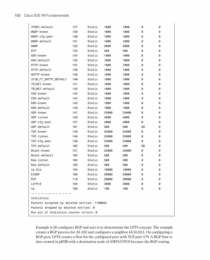
Example 6-18 configures BGP and uses it to demonstrate the LPTS concept. The examplecreates a BGP process for AS 102 and configures a neighbor 65.10.20.2. On configuring aBGP peer, LPTS creates a flow for the configured peer with TCP port 179. A BGP flow isalso created in pIFIB with a destination node of 0/RP1/CPU0 because the BGP routing
07_1587052717_ch06.qxp 5/15/09 11:21 AM Page 190
Chapter 6: Cisco IOS XR Security 191
protocol runs on the RP of the router and the active RP is the destination node for BGPpackets.
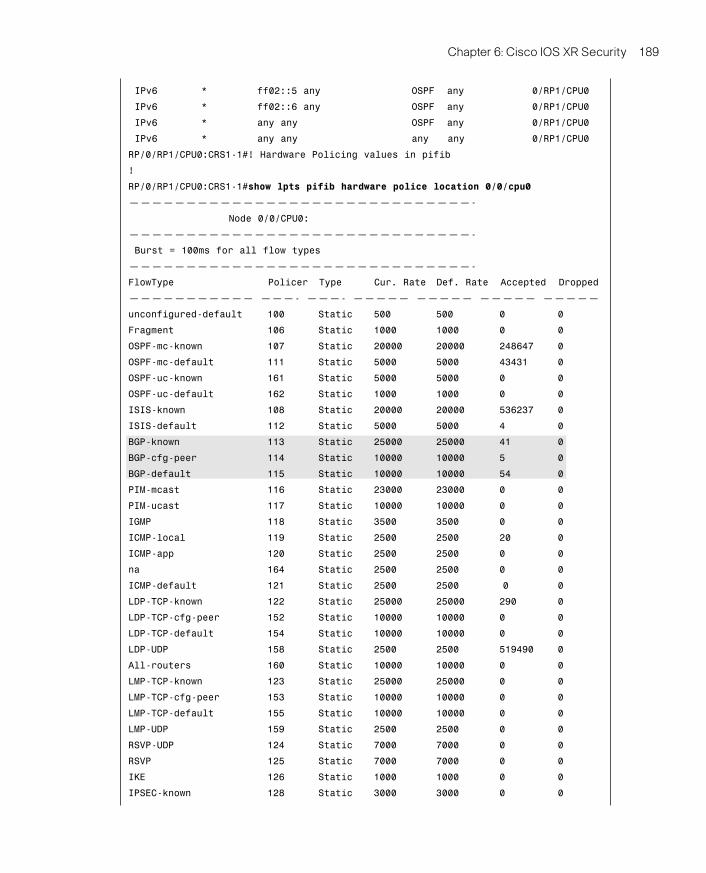
Example 6-18 shows the policer in line card hardware and shows three different policersfor BGP, which exist regardless of BGP configuration. Policer 113 in the example for BGPflow type BGP-known signifies a well established BGP session that actively participates inBGP route advertisement. Policer 114 BGP-cfg-peer represents a new session or recentlyestablished session that has not yet elevated to a level of an established session. BGP-de-fault identified by policer 115 represents a default entry for BGP flow. This flow also helpswith any latency in hardware programming for new configurations or accounts for a TCPsession that might be initiated to port 179 for debugging purposes. The example shows ahigher policer rate of 25,000 packets per second (pps) for established sessions comparedto 10,000 pps for all other categories of BGP traffic flows.
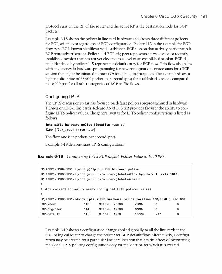
Configuring LPTS
The LPTS discussion so far has focused on default policers preprogrammed in hardwareTCAMs on CRS-1 line cards. Release 3.6 of IOS XR provides the user the ability to con-figure LPTS policer values. The general syntax for LPTS policer configurations is listed asfollows:
lpts pifib hardware police [location node-id]
flow {flow_type} {rate rate}
The flow rate is in packets per second (pps).
Example 6-19 demonstrates LPTS configuration.
Example 6-19 Configuring LPTS BGP-default Policer Value to 1000 PPS
RP/0/RP1/CPU0:CRS1-1(config)#lpts pifib hardware police
RP/0/RP1/CPU0:CRS1-1(config-pifib-policer-global)#flow bgp default rate 1000
RP/0/RP1/CPU0:CRS1-1(config-pifib-policer-global)#commit
!
! show command to verify newly configured LPTS policer values
!
RP/0/RP1/CPU0:CRS1-1#show lpts pifib hardware police location 0/0/cpu0 | inc BGP
BGP-known 113 Static 25000 25000 0 0
BGP-cfg-peer 114 Static 10000 10000 0 0
BGP-default 115 Global 1000 10000 237 0
Example 6-19 shows a configuration change applied globally to all the line cards in theSDR or logical router to change the policer for BGP-default flow. Alternatively, a configu-ration may be created for a particular line card location that has the effect of overwritingthe global LPTS policing configuration only for the location for which it is created.
07_1587052717_ch06.qxp 5/15/09 11:21 AM Page 191
192 Cisco IOS XR Fundamentals
SummaryThis chapter discussed Cisco IOS XR security aspects. In this chapter we explored theAAA feature and its configuration aspects that are used in managing access to a routerrunning the IOS XR operating system. Although the concepts of AAA are independent ofplatform and operating system, IOS XR exhibits key characteristics of a large-scale oper-ating system that has unique requirements, such as elaborate access policies. This chapterintroduced the IOS XR concepts of predefined users such as root-system, root-lr, netadmin, and cisco-support—each of which has well-defined roles and privileges.
IOS XR’s AAA model contains the notion of task permissions for any control, configure,or monitor operation. Tasks are represented as task IDs. A task ID defines the permissionto execute an operation for a given user. If the user is associated with a task ID through auser group, that user can execute any of the operations associated with that task ID. AllIOS XR CLI are associated with one or more task IDs. Task IDs always imply granted per-mission and not denied ones. Furthermore, task IDs are always associated with one of thetask classes: READ, WRITE, EXECUTE, or DEBUG.
AAA provides transparent use of local, on-the-box authentication as well as remote au-thentication done with an external TACACS+ or RADIUS server.
This chapter also briefly introduced Secure Shell (SSH), access lists, and uRPF features.This chapter elucidated the concepts behind Local Packet Transport Service (LPTS) in pro-viding an integral firewall for the IOS XR running router.
References■ Cisco. Configuring AAA Services on Cisco IOS XR Software. http://www.cisco.com/
■ Cisco. Implementing Management Plane Protection on Cisco IOS XR Software.http://www.cisco.com/
■ Cisco. Implementing LPTS on Cisco IOS XR Software. http://www.cisco.com/
■ Cisco. Implementing Access Lists and Prefix Lists on Cisco IOS XR Software.http://www.cisco.com/
07_1587052717_ch06.qxp 5/15/09 11:21 AM Page 192
Top Related