


Languages
Pages
Legal


Cisco Collaboration on Virtual ServersFirst Published: 2016-06-07
Americas HeadquartersCisco Systems, Inc.170 West Tasman DriveSan Jose, CA 95134-1706USAhttp://www.cisco.comTel: 408 526-4000 800 553-NETS (6387)Fax: 408 527-0883
Text Part Number: OL-25228-02
THE SPECIFICATIONS AND INFORMATION REGARDING THE PRODUCTS IN THIS MANUAL ARE SUBJECT TO CHANGE WITHOUT NOTICE. ALL STATEMENTS,INFORMATION, AND RECOMMENDATIONS IN THIS MANUAL ARE BELIEVED TO BE ACCURATE BUT ARE PRESENTED WITHOUT WARRANTY OF ANY KIND,EXPRESS OR IMPLIED. USERS MUST TAKE FULL RESPONSIBILITY FOR THEIR APPLICATION OF ANY PRODUCTS.
THE SOFTWARE LICENSE AND LIMITEDWARRANTY FOR THE ACCOMPANYING PRODUCT ARE SET FORTH IN THE INFORMATION PACKET THAT SHIPPED WITHTHE PRODUCT AND ARE INCORPORATED HEREIN BY THIS REFERENCE. IF YOU ARE UNABLE TO LOCATE THE SOFTWARE LICENSE OR LIMITED WARRANTY,CONTACT YOUR CISCO REPRESENTATIVE FOR A COPY.
The Cisco implementation of TCP header compression is an adaptation of a program developed by the University of California, Berkeley (UCB) as part of UCB's public domain versionof the UNIX operating system. All rights reserved. Copyright © 1981, Regents of the University of California.
NOTWITHSTANDINGANYOTHERWARRANTYHEREIN, ALL DOCUMENT FILES AND SOFTWARE OF THESE SUPPLIERS ARE PROVIDED “AS IS"WITH ALL FAULTS.CISCO AND THE ABOVE-NAMED SUPPLIERS DISCLAIM ALL WARRANTIES, EXPRESSED OR IMPLIED, INCLUDING, WITHOUT LIMITATION, THOSE OFMERCHANTABILITY, FITNESS FORA PARTICULAR PURPOSEANDNONINFRINGEMENTORARISING FROMACOURSEOFDEALING, USAGE, OR TRADE PRACTICE.
IN NO EVENT SHALL CISCO OR ITS SUPPLIERS BE LIABLE FOR ANY INDIRECT, SPECIAL, CONSEQUENTIAL, OR INCIDENTAL DAMAGES, INCLUDING, WITHOUTLIMITATION, LOST PROFITS OR LOSS OR DAMAGE TO DATA ARISING OUT OF THE USE OR INABILITY TO USE THIS MANUAL, EVEN IF CISCO OR ITS SUPPLIERSHAVE BEEN ADVISED OF THE POSSIBILITY OF SUCH DAMAGES.
Any Internet Protocol (IP) addresses and phone numbers used in this document are not intended to be actual addresses and phone numbers. Any examples, command display output, networktopology diagrams, and other figures included in the document are shown for illustrative purposes only. Any use of actual IP addresses or phone numbers in illustrative content is unintentionaland coincidental.
Cisco and the Cisco logo are trademarks or registered trademarks of Cisco and/or its affiliates in the U.S. and other countries. To view a list of Cisco trademarks, go to this URL: http://www.cisco.com/go/trademarks. Third-party trademarks mentioned are the property of their respective owners. The use of the word partner does not imply a partnershiprelationship between Cisco and any other company. (1110R)
THE SPECIFICATIONS AND INFORMATION REGARDING THE PRODUCTS IN THIS MANUAL ARE SUBJECT TO CHANGE WITHOUT NOTICE. ALL STATEMENTS,INFORMATION, AND RECOMMENDATIONS IN THIS MANUAL ARE BELIEVED TO BE ACCURATE BUT ARE PRESENTED WITHOUT WARRANTY OF ANY KIND,EXPRESS OR IMPLIED. USERS MUST TAKE FULL RESPONSIBILITY FOR THEIR APPLICATION OF ANY PRODUCTS.
THE SOFTWARE LICENSE AND LIMITEDWARRANTY FOR THE ACCOMPANYING PRODUCT ARE SET FORTH IN THE INFORMATION PACKET THAT SHIPPED WITHTHE PRODUCT AND ARE INCORPORATED HEREIN BY THIS REFERENCE. IF YOU ARE UNABLE TO LOCATE THE SOFTWARE LICENSE OR LIMITED WARRANTY,CONTACT YOUR CISCO REPRESENTATIVE FOR A COPY.
The following information is for FCC compliance of Class A devices: This equipment has been tested and found to comply with the limits for a Class A digital device, pursuant to part 15of the FCC rules. These limits are designed to provide reasonable protection against harmful interference when the equipment is operated in a commercial environment. This equipmentgenerates, uses, and can radiate radio-frequency energy and, if not installed and used in accordance with the instruction manual, may cause harmful interference to radio communications.Operation of this equipment in a residential area is likely to cause harmful interference, in which case users will be required to correct the interference at their own expense.
The following information is for FCC compliance of Class B devices: This equipment has been tested and found to comply with the limits for a Class B digital device, pursuant to part 15of the FCC rules. These limits are designed to provide reasonable protection against harmful interference in a residential installation. This equipment generates, uses and can radiate radiofrequency energy and, if not installed and used in accordance with the instructions, may cause harmful interference to radio communications. However, there is no guarantee that interferencewill not occur in a particular installation. If the equipment causes interference to radio or television reception, which can be determined by turning the equipment off and on, users areencouraged to try to correct the interference by using one or more of the following measures:
• Reorient or relocate the receiving antenna.
• Increase the separation between the equipment and receiver.
• Connect the equipment into an outlet on a circuit different from that to which the receiver is connected.
• Consult the dealer or an experienced radio/TV technician for help.
Modifications to this product not authorized by Cisco could void the FCC approval and negate your authority to operate the product
The Cisco implementation of TCP header compression is an adaptation of a program developed by the University of California, Berkeley (UCB) as part of UCB’s public domain versionof the UNIX operating system. All rights reserved. Copyright © 1981, Regents of the University of California.
NOTWITHSTANDINGANYOTHERWARRANTYHEREIN, ALL DOCUMENT FILES AND SOFTWAREOF THESE SUPPLIERS ARE PROVIDED "AS IS"WITHALL FAULTS.CISCO AND THE ABOVE-NAMED SUPPLIERS DISCLAIM ALL WARRANTIES, EXPRESSED OR IMPLIED, INCLUDING, WITHOUT LIMITATION, THOSE OFMERCHANTABILITY, FITNESS FORA PARTICULAR PURPOSEANDNONINFRINGEMENTORARISING FROMACOURSEOFDEALING, USAGE, OR TRADE PRACTICE.
IN NO EVENT SHALL CISCO OR ITS SUPPLIERS BE LIABLE FOR ANY INDIRECT, SPECIAL, CONSEQUENTIAL, OR INCIDENTAL DAMAGES, INCLUDING, WITHOUTLIMITATION, LOST PROFITS OR LOSS OR DAMAGE TO DATA ARISING OUT OF THE USE OR INABILITY TO USE THIS MANUAL, EVEN IF CISCO OR ITS SUPPLIERSHAVE BEEN ADVISED OF THE POSSIBILITY OF SUCH DAMAGES.
Any Internet Protocol (IP) addresses and phone numbers used in this document are not intended to be actual addresses and phone numbers. Any examples, command display output, networktopology diagrams, and other figures included in the document are shown for illustrative purposes only. Any use of actual IP addresses or phone numbers in illustrative content is unintentionaland coincidental.
Cisco and the Cisco logo are trademarks or registered trademarks of Cisco and/or its affiliates in the U.S. and other countries. To view a list of Cisco trademarks, go to this URL: http://www.cisco.com/go/trademarks. Third-party trademarks mentioned are the property of their respective owners. The use of the word partner does not imply a partnershiprelationship between Cisco and any other company. (1110R)

© 2017 Cisco Systems, Inc. All rights reserved.

C O N T E N T S
C H A P T E R 1 Preparation 1
Introduction 1
Installation and Migration Scenarios 1
System Requirements 3
External Media for Cisco Collaboration Applications 5
Cisco Unified Communications Manager VMware Tools and ESXi 5
Requirements for Cisco UCS Server Installation 5
C H A P T E R 2 Installation and Configuration 9
Install Cisco UCS B-Series Blade Server 9
Cisco UCS C-Series and E-Series Server Installation and Configuration Task Flow 10
Install Cisco UCS C-Series or E-Series Server 11
Configure Cisco Integrated Management Controller 11
RAID Configuration 13
Configure RAID with Preboot CLI (UCS C-Series M2 or M3 Servers) 15
Configure RAID with GUI (UCS C-Series M3 Servers) 20
Configure RAID with GUI (UCS C-SeriesM4 Servers) 21
Configure RAID with GUI (UCS E-Series M2 Servers) 22
Configure RAID with GUI (UCS E-Series M3 Servers) 22
Configure BIOS 23
Install and Configure VMware ESXi 24
Download Virtual Machine Templates (OVA Templates) 25
ISO and VM Template Delivery 26
Use vSphere to Create the VM for Servers with Optical Drives 26
Use vSphere to Create the VM for Servers Without Optical Drives 26
Install Cisco Collaboration Applications on VMs 27
Cisco Collaboration on Virtual Serversiv OL-25228-02
Contents

C H A P T E R 3 Migration 29
Migrate to Cisco UCS B-Series Blade Servers 29
Migrate to Cisco UCS Rack-Mount Server 31
Migrate Cisco Unity Connection on a Virtual Machine 33
C H A P T E R 4 Administration 35
Rack-Mount Server Daily Operations 35
Monitoring From Virtual Machine 36
Monitoring From Cisco Integrated Management Controller 36
Monitoring From vSphere Client and vCenter 36
Server Health Monitoring From ESXi 36
Disk Management for Cisco UCS Rack-Mount Servers 36
Automatic Update Statistics 37
New Identity 37
Run New Identity Process 37
New Identity Caveats 38
Deploy Cluster Nodes Using Templates 38
Licensing Cisco Unified CM on Virtualized Servers 38
New Licensing Procedure Customer Impact 39
Virtual Machine Setup and Licensing Support 40
Related Documentation 40
Cisco Collaboration on Virtual Servers OL-25228-02 v
Contents

C H A P T E R 1Preparation
• Introduction, page 1
• Installation and Migration Scenarios, page 1
• System Requirements, page 3
• External Media for Cisco Collaboration Applications, page 5
• Cisco Unified Communications Manager VMware Tools and ESXi, page 5
• Requirements for Cisco UCS Server Installation, page 5
IntroductionThis book provides an overview of how to install and migrate to virtual servers for Cisco Collaborationapplications.
For Cisco Business Edition 6000 and 7000 appliance servers, do not follow the procedures in this documentas the appliance servers ship with factory-setup hardware and factory-preloaded software and you willoverwrite the preloaded software. Instead, use the Cisco Business Edition 6000 or 7000 Installation Guideat www.cisco.com/go/be6000 or www.cisco.com/go/be7000. Follow this document only if you mustrebuild your appliance server from scratch, such as after hardware replacement or recovering from acatastrophic event.
Note
Installation and Migration ScenariosFor ordering information and part numbers, see the Business Edition datasheets at www.cisco.com/go/be6000or www.cisco.com/go/be7000 and the Tested Reference Configurations at http://docwiki.cisco.com/wiki/UC_Virtualization_Supported_Hardware#Table_1_-_UC_on_UCS_TRCs.
Cisco Collaboration on Virtual Servers OL-25228-02 1

Table 1: UCS C-Series Tested Reference Configurations
Packaged CollaborationSolution Name**
UC on UCS TRC Name*Form FactorTRC Capacity
N/AUCS C260 M2 TRC#12RU rack-mount serverExtra-Large TRC
Cisco Business Edition7000H (M4)
UCSC240M4SXTRC#12RU rack-mount serverLarge TRC
N/AUCS C240 M3S TRC#1
Cisco Business Edition7000M (M4)
UCS C240M4S2 TRC#12RU rack-mount serverMedium TRC
Cisco Business Edition7000M (M3)
UCS C240 M3S TRC#22RU rack-mount server
N/AUCS C220 M3S TRC#11RU rack-mount server
N/AUCS C210 M2 TRCs#1,2,3
2RU rack-mount server
N/AUCS C210 M1 TRCs#1,2,3,4
Cisco Business Edition6000H (M4)
UCS C220 M4S TRC#21RU rack-mount serverSmall Plus TRC
Cisco Business Edition6000H (M3)
UCS C220 M3S TRC#3
Cisco Business Edition6000M (M4)
UCS C220 M4S TRC#11RU rack-mount serverSmall TRC
Cisco Business Edition6000M (M3)
UCS C220 M3S TRC#2
Cisco Business Edition6000M (M2)
UCS C200 M2 TRC#1
* When purchased as a UC on UCS TRC, there is no factory-setup or factory-installation of the hardware orsoftware. Follow instructions in this doc for first time setup or rebuilds.
** When purchased as a Cisco Business Edition solution, the hardware is factory-setup and the software isfactory-installed. For first-time-setup, DO NOT follow the instructions in this doc or you will overwrite thepreload. Instead, follow the Cisco Business Edition Installation Guides at either www.cisco.com/go/be6000or www.cisco.com/go/be7000 . Follow the instructions in this document only if you have to rebuild a BE6000or BE7000 server from scratch.
Cisco Collaboration on Virtual Servers2 OL-25228-02
PreparationInstallation and Migration Scenarios

Table 2: UCS B-Series Tested Reference Configurations
UC on UCS TRC NameForm FactorTRC Capacity
UCS B440 M2 TRC#1Full-width blade serverExtra-Extra-Large Blade TRC
UCS B230 M2 TRC#1Half-width blade serverExtra-Large Blade TRC
UCS B200 M4 TRC#1Half-width blade serverLarge Blade TRC
UCS B200 M3 TRC#1
UCS B200 M2/M1 TRCsHalf-width blade serverMedium Blade TRCs
Table 3: UCS E-Series Tested Reference Configurations
Packaged CollaborationSolution Name**
UC on UCS TRC NameForm FactorTRC Capacity
Blade server component ofCisco Business Edition 6000S(M2) appliance
UCS E160D M2TRC#1
Double-wide bladeserver for CiscoIntegrated Services(Cisco ISR)
Extra-Small TRC
N/AUCSE160SM3TRC#1Single-wide bladeserver for CiscoIntegrated Services(Cisco ISR)
Extra-Small TRC
* When purchased as a UC on UCS TRC, the hardware definition is only for the UCS E-Series blade serverand not for the Cisco ISR router housing the server. There is also no factory-setup or factory-installation ofthe hardware or software. Follow instructions in this doc for first time setup or rebuilds of the blade server.See http://www.cisco.com/go/isr for documentation on Cisco ISR routers.
**When purchased as a Cisco Business Edition solution, the Cisco ISR router and UCS E-Series blade serverhardware are factory-setup and the software is factory-installed. For first-time-setup, DO NOT follow theinstructions in this doc or you will overwrite the preload. Instead, follow the Cisco Business Edition 6000Installation Guides at http://www.cisco.com/go/be6000. Follow the instructions in this document only if youhave to rebuild a BE6000 or BE7000 server from scratch.
System Requirements• This document is for virtualized Cisco UCS servers configured as Tested Reference Configurations(TRCs) for the UC on UCS. For more information see http://www.cisco.com/go/uconucs, and http://www.cisco.com/go/uc-virtualized.
• For newly purchased/installed Cisco Business Edition 6000 and 7000 appliance servers, do not followthe procedures in this document because your server ships with factory-setup hardware and preloaded
Cisco Collaboration on Virtual Servers OL-25228-02 3
PreparationSystem Requirements

software. If you follow the procedures in this document, you will overwrite the preloaded software andlicensing. Instead, use the Cisco Business Edition 6000 or 7000 Installation Guide at www.cisco.com/go/be6000 or www.cisco.com/go/be7000. Follow this document only if you must rebuild your serverfrom scratch such as recovering from a catastrophic event.
• If you want to deploy Cisco Collaboration on a virtualized 3rd-party Specs-based server or Cisco UCSSpecs-based server, see the application support information at http://www.cisco.com/go/uc-virtualized,and the Specs-based support information at http://docwiki.cisco.com/wiki/UC_Virtualization_Supported_Hardware. Installation procedures will vary from this document and can be found at vmware.com, http://www.cisco.com/go/ucs, or the 3rd-party server vendor's website.
• Additional detail on supported virtualization software vendors, products, versions and features can befound at http://docwiki.cisco.com/wiki/Unified_Communications_VMWare_Requirements.
To run Cisco UCS servers, your system must meet the requirements listed in the following table.
Table 4: System Requirements
ValueParameter
See the application links at http://www.cisco.com/go/uc-virtualized.
See sizing information at http://docwiki.cisco.com/wiki/Unified_Communications_Virtualization_Sizing_Guidelines and http://www.cisco.com/go/vmpt.
Supported ApplicationCo-residency andVirtual-to-Physical Sizing
Refer to the documentation at: http://www.cisco.com/go/uc-virtualized
To ensure that the VMs are correctly configured, use the Cisco-providedOVA template to create VMs. Refer to Download Virtual MachineTemplates (OVA Templates), on page 25
For more information about virtual machine configurations, refer tothe documentation at: http://docwiki.cisco.com/wiki/Unified_Communications_Virtualization_Sizing_Guidelines#OVAs.2C_VMs.2C_Users_and_Servers .
Supported Virtual MachineConfiguration
See http://docwiki.cisco.com/wiki/Unified_Communications_VMWare_Requirements
Supported virtualization softwarevendors, products, versions andfeatures
See http://www.cisco.com/go/uc-virtualized and http://docwiki.cisco.com/wiki/UC_Virtualization_Supported_Hardware.
Supported hardware
NoneCPU and RAM over subscription
See http://docwiki.cisco.com/wiki/UC_Virtualization_Supported_Hardware#Storage and the application links at http://www.cisco.com/go/uc-virtualized
Storage capacity and IOPSrequirements
To operate Cisco UCS servers successfully, you should have the experience and skills to manage a host serverrunning VMware ESXi.
Cisco Collaboration on Virtual Servers4 OL-25228-02
PreparationSystem Requirements
External Media for Cisco Collaboration ApplicationsCisco UCS servers use “soft media” such as ISO or FLP (virtual floppy) for procedures that require externalmedia (such as installation and upgrade). Physical external devices such as USB drives are not supported.
Backup and restore for Cisco Collaboration applications are not supported on soft media.Note
The virtual USB interface is not supported for Cisco Collaboration applications running on VMware. Thefollowing are examples of differences in external media support between non-virtualized Cisco MediaConvergence servers and virtualized Cisco UCS servers:
• Install logs cannot be dumped to a USB key. These logs are dumped to a file through the serial port ofthe VM.
• The answer file that is generated by the Answer File Generator (platformConfig.xml) cannot be readfrom a USB key to perform an unattended installation. Instead, you must put the answer file into an FLPimage to be mounted in the floppy drive.
• USB tape drive backup is not supported. Use SFTP instead.
• Music On Hold through a USB connection is not supported. Use multicast MOH instead.
Cisco Unified Communications Manager VMware Tools andESXi
VMware Tools are specialized drivers for virtual hardware that is installed in the UC applications when theyare running virtualized. It is very important that the VMware tools version running in the UC application bein sync with the version of ESXi being used. For information on how to upgrade the tools, see:
http://docwiki.cisco.com/wiki/VMware_Tools.
Requirements for Cisco UCS Server InstallationThis section describes how to prepare to install a Cisco UCS Server in a standalone configuration (it is not ina datacenter).
If your server is ordered as a Cisco Business Edition 6000 or Cisco Business Edition 7000, the serverships with factory-setup hardware and factory-preloaded software. DO NOT follow the configurationprocedures that are outlined in this document or you will overwrite the preloaded software. Follow thisdocument only if you must rebuild your server from scratch. Unless you are rebuilding your server fromscratch, such as recovering from a catastrophic situation, use the Installation Guides for Cisco BusinessEdition 6000 or 7000 at www.cisco.com/go/be6000 or www.cisco.com/go/be7000.
Caution
Cisco suggests that you allocate the following resources before installation:
Cisco Collaboration on Virtual Servers OL-25228-02 5
PreparationExternal Media for Cisco Collaboration Applications
• Space in a rack to receive the Cisco C-Series rack-mount server, Cisco ISR housing UCS E-Series bladeserver, or UCS 5100 Blade Server Chassis housing UCS B-Series blade server and its UCS6300/6200/6100 Fabric Interconnect Switches.
• Ethernet ports on a switch close to the Cisco UCS Server. For port details specific to your server, seethe below table.
• An IP address for Cisco IMC or UCS Manager management. If the dedicated port is used, attach it tothe appropriate LAN.
• A VLAN ID and IP address for the host. This address is the Cisco UCS Server ESXi managementaddress.
• A hostname and configured DNS, if desired, for the hostname.
• VLAN IDs and IP addresses for the VMs.
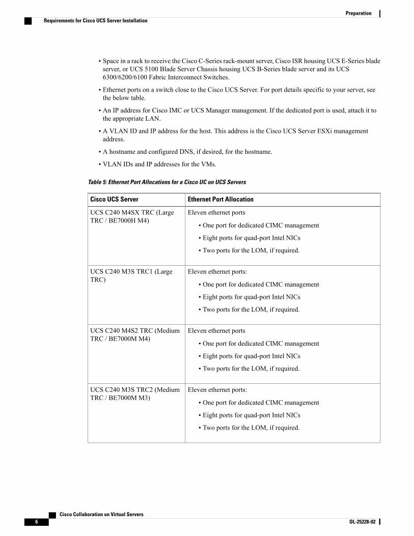
Table 5: Ethernet Port Allocations for a Cisco UC on UCS Servers
Ethernet Port AllocationCisco UCS Server
Eleven ethernet ports
• One port for dedicated CIMC management
• Eight ports for quad-port Intel NICs
• Two ports for the LOM, if required.
UCS C240 M4SX TRC (LargeTRC / BE7000H M4)
Eleven ethernet ports:
• One port for dedicated CIMC management
• Eight ports for quad-port Intel NICs
• Two ports for the LOM, if required.
UCS C240 M3S TRC1 (LargeTRC)
Eleven ethernet ports
• One port for dedicated CIMC management
• Eight ports for quad-port Intel NICs
• Two ports for the LOM, if required.
UCS C240 M4S2 TRC (MediumTRC / BE7000M M4)
Eleven ethernet ports:
• One port for dedicated CIMC management
• Eight ports for quad-port Intel NICs
• Two ports for the LOM, if required.
UCS C240 M3S TRC2 (MediumTRC / BE7000M M3)
Cisco Collaboration on Virtual Servers6 OL-25228-02
PreparationRequirements for Cisco UCS Server Installation

Ethernet Port AllocationCisco UCS Server
For Small TRC:
Three ethernet ports:
• One port for dedicated CIMC management
• Two ports for the LOM, if required.
For Small Plus or Medium TRC:
Seven ethernet ports:
• One port for dedicated CIMC management
• Four ports for quad-port Intel NICs
• Two ports for the LOM, if required.
UCSC220M4STRCs (Small TRC/ BE6000M M4 and Small PlusTRC / BE6000H M4)
For Small TRC:
Three ethernet ports:
• One port for dedicated CIMC management
• Two ports for the LOM, if required.
For Small Plus or Medium TRC:
Seven ethernet ports:
• One port for dedicated CIMC management
• Four ports for quad-port Intel NICs
• Two ports for the LOM, if required.
UCSC220M3STRCs (Small TRC/ BE6000M M3, Small Plus TRC/ BE6000HM3 andMediumTRC)
3 "external" (front of E160D M2) ethernet ports:
• One "M" port for dedicated CIMC management (CIMC is alsoaccessible via the "internal" ports described below)
• Two ports for LAN access
• The two "internal" ports of the UCS E-Series server are to ISRbackplane for connectivity to other ISR interfaces.
UCS E160D M2 TRC1(Extra-Small TRC / BE6000SM2)
3 "external" (front of E160D M2) ethernet ports:
• One "M" port for dedicated CIMC management (CIMC is alsoaccessible via the "internal" ports described below)
• Two ports for LAN access
• The two "internal" ports of the UCS E-Series server are to ISRbackplane for connectivity to other ISR interfaces.
UCSE160SM3TRC1(Extra-SmallTRC)
Cisco Collaboration on Virtual Servers OL-25228-02 7
PreparationRequirements for Cisco UCS Server Installation

Ethernet Port AllocationCisco UCS Server
Ten ethernet ports:
• One port for dedicated Cisco Integrated Management Controller(CIMC) management
• Four ports for quad-port Intel NICs
• Two ports for the LAN on Motherboard (LOM)
• Two 10-Gigabit Modular LOM
End-of-Sale UCS C260 M2 TRC1(Extra-Large TRCs)
Seven ethernet ports
• One port for dedicated CIMC management
• Four ports for quad-port Intel NICs
• Two ports for the LOM
End of Sale UCS C210 M2/M1TRCs (Medium TRCs)
Three ethernet ports:
• One port for dedicated CIMC management
• Two ports for the LOM
End of Sale UCS C200 M2 TRC1(Small TRC / BE6000M M2)
Cisco Collaboration on Virtual Servers8 OL-25228-02
PreparationRequirements for Cisco UCS Server Installation

C H A P T E R 2Installation and Configuration
The Extra-Small TRC (UCS E160D M2 TRC1), Small TRCs (UCS C220 M3S TRC2, UCS C240 M4STRC1) and the Small Plus TRCs (UCS C220 M3S TRC3, UCS C220 M4S TRC2) are preloaded withsoftware if purchased as part of Cisco Business Edition 6000.
Certain Medium TRCs (UCS C240 M3S TRC2, UCS C240 M4S2 TRC1) and Large TRCs (UCS C240M4SX TRC1) are preloaded with software if purchased as part of Cisco Business Edition 7000.
Install Cisco UCS B-Series Blade Server, on page 9
Cisco UCS C-Series and E-Series Server Installation and Configuration Task Flow, on page 10
Caution
• Install Cisco UCS B-Series Blade Server, page 9
• Cisco UCS C-Series and E-Series Server Installation and Configuration Task Flow, page 10
Install Cisco UCS B-Series Blade ServerProcedure
Step 1 Ensure that your UCS Mini or Fabric Interconnect Switches, Blade Server Chassis, and Fabric Extenders areinstalled in the rack
Step 2 Ensure that the network connections of your UCSMini or Fabric Interconnect Switches are connected to theirdesignated, trunked, switch ports.
Step 3 Ensure that your Fabric Interconnect Switches are properly connected to your Fabric Extenders.Step 4 Ensure that you are able to access the blade remotely using UCS Manager software.Step 5 For the remaining server installation, see Cisco documentation at http://www.cisco.com/go/ucs.
Cisco Collaboration on Virtual Servers OL-25228-02 9

Cisco UCS C-Series and E-Series Server Installation andConfiguration Task Flow
Perform the following tasks to install and configure a virtual machine on a Cisco UCS server.
Before You Begin
Review chapter 1 of this book for the installation requirements for your server:
• Preparation, on page 1
Procedure
PurposeCommand or Action
Install the Cisco UCS Server.Install Cisco UCS C-Series or E-Series Server , onpage 11
Step 1
Power on the server and configure CiscoIntegratedManagement Controller (CIMC)for remote management.
Configure Cisco IntegratedManagement Controller,on page 11
Step 2
Configure the RAID settings on your serverusing either the Preboot CLI or GUIindicated above.
Configure RAID using one of the followingprocedures:
Step 3
• Configure RAID with Preboot CLI (UCSC-Series M2 or M3 Servers) , on page 15
• Configure RAIDwith GUI (UCS C-SeriesM3Servers), on page 20
• Configure RAID with GUI (UCS C-SeriesM4Servers), on page 21
• Configure RAID with GUI (UCS E-Series M2Servers), on page 22
• Configure RAIDwith GUI (UCS C-SeriesM3Servers), on page 20
Configure the BIOS boot order.Configure BIOS, on page 23Step 4
Install and configure the VMware ESXi andthe vSphere client.
Install and Configure VMware ESXi, on page 24Step 5
Download an OVA for collaborationapplication software, such as Cisco Unified
Download Virtual Machine Templates (OVATemplates), on page 25
Step 6
Communications Manager, onto yourvirtual machine.
Cisco Collaboration on Virtual Servers10 OL-25228-02
Installation and ConfigurationCisco UCS C-Series and E-Series Server Installation and Configuration Task Flow

PurposeCommand or Action
Use vSphere to create the VM on the server.Map the OVA to the VM.
Use vSphere to create the VM on the server:Step 7
• Use vSphere to Create the VM for Servers withOptical Drives, on page 26
• Use vSphere to Create the VM for ServersWithout Optical Drives, on page 26
Install Collaboration applications such asCisco Unified Communications Manageron the virtual machine.
Install Cisco Collaboration Applications on VMs,on page 27
Step 8
Install Cisco UCS C-Series or E-Series Server
Procedure
Step 1 If UCS C-Series, install the server in the rack. If UCS E-Series, install the Cisco ISR in the rack and installethe UCS E-Series blade server into the ISR
Step 2 Attach the Cisco Integrated Management Controller (Cisco IMC) of the Cisco UCS C-Series or E-Seriesmanagement port to the designated switch port.
Step 3 Attach the UCS C-Series LAN on Motherboard (LOM) or NIC ports (or the UCS E-Series external ethernetports if used instead of internal ethernet ports) to their designated, trunked switch ports
Step 4 Attach a VGA console, or a KVM to the VGA and keyboard ports. This step is necessary until Cisco IMC isconfigured.
Step 5 Attach UCS C server or Cisco ISR for UCS E server to power supply
What to Do Next
Configure Cisco Integrated Management Controller, on page 11
Configure Cisco Integrated Management ControllerConfiguring the Cisco IMC allows you to perform all subsequent configuration and installation using theCisco IMC console. In addition, the Cisco IMC provides a measure of hardware monitoring.
Cisco Collaboration on Virtual Servers OL-25228-02 11
Installation and ConfigurationInstall Cisco UCS C-Series or E-Series Server

Virtualized Collaboration Applications does not prescribe any specific version of BIOS. The currentversion is assumed to be compatible with the latest release of ESXi. Business Edition appliances ship withBIOS version, configuration and settings that are compatible with the factory-preloaded release of ESXiat time of appliance build. Non-appliance servers, or appliances that have been in the field for extendedperiod of time, may require modification of these settings. See the UCSRelease, CIMC version or firmwarepackage in UCS Interoperability Matrix as well as UCS OS drivers for ESXi.
Note
Before You Begin
Install Cisco UCS C-Series or E-Series Server , on page 11
Procedure
Step 1 Power on server.Step 2 During boot, press indicated function key (e.g. F8 for a UCS C-Series) to enter Cisco IMC configuration.Step 3 In the Cisco IMC configuration screen, under IPV4 (Basic):
a) Uncheck the DHCP enabled check box using the spacebar.b) Enter values for the Cisco IMC IP, Subnet mask, and Gateway.
Step 4 Leave VLAN (Advanced) unchecked.Step 5 Under Default User (Basic), enter the default Cisco IMC user, admin, and a password.
The Cisco IMC username is not configurable and the setting is "admin."Note
Step 6 Press indicated function key (e.g. F10 for a UCS C-Series) to save your settings.Step 7 After it is configured, the Cisco IMC is accessible using http. Point a browser to the IP address configured
above and log in as admin, using the password configured above.
What to Do Next
Review the table in RAID Configuration, on page 13
Configure RAID using one of the following three methods:
• Configure RAID with Preboot CLI (UCS C-Series M2 or M3 Servers) , on page 15
• Configure RAID with GUI (UCS C-Series M3 Servers), on page 20
• Configure RAID with GUI (UCS C-SeriesM4 Servers), on page 21
• Configure RAID with GUI (UCS E-Series M2 Servers), on page 22
Cisco Collaboration on Virtual Servers12 OL-25228-02
Installation and ConfigurationConfigure Cisco Integrated Management Controller

RAID Configuration
To be supported as a Tested Reference Configuration instead of UCS Specs-based, the RAID must besetup exactly as indicated below. Do not change the RAID configuration on a server ordered as CiscoBusiness Edition 6000 or Cisco Business Edition 7000.
Caution
Refer to the following table for the RAID specifications for the type of virtual machine that you want toconfigure.
InformationTRC
• Two virtual drives (VD) with RAID-5 arrays
• Eight 300 GB hard drives for each VD
UCS C240 M3S TRC1 (Large TRC)
• Two virtual drives (VD) with RAID-5 arrays
• Six 300-GB hard drives for each VD
UCS C240 M3S TRC2 (Medium TRC /BE7000M M3)
• One virtual drive with a RAID-5 array
• Eight 300-GB hard drives
UCS C220 M3S (Medium TRC)
• One virtual drive with a RAID-5 array
• Eight 300-GB hard drives
UCS C220 M3S TRC3 (Small Plus TRC/ BE6000H M3)
• One virtual drive with a RAID-10 array
• Four 500-GB hard drives
UCS C220 M3S TRC2 (Small TRC /BE6000M M3)
• One virtual drive with a RAID-5 array
• Three 600-GB hard drives
UCSE160DM2TRC1 (Extra-Small TRC/ BE6000S M2)
• One virtual drive with a RAID-1 array- Two 900-GB harddrives
UCSE160SM3TRC1 (Extra-Small TRC)
• Two virtual drives (VD) with RAID-5 arrays
• Eight 300 GB hard drives for each VD
End of Sale UCS C260 M2 TRC1(Extra-Large TRC)
Cisco Collaboration on Virtual Servers OL-25228-02 13
Installation and ConfigurationRAID Configuration
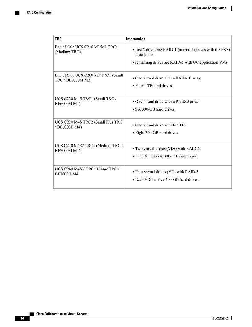
InformationTRC
• first 2 drives are RAID-1 (mirrored) drives with the ESXiinstallation.
• remaining drives are RAID-5 with UC application VMs.
End of Sale UCS C210 M2/M1 TRCs(Medium TRC)
• One virtual drive with a RAID-10 array
• Four 1 TB hard drives
End of Sale UCS C200 M2 TRC1 (SmallTRC / BE6000M M2)
• One virtual drive with a RAID-5 array
• Six 300-GB hard drives
UCS C220 M4S TRC1 (Small TRC /BE6000M M4)
• One virtual drive with RAID-5
• Eight 300-GB hard drives
UCS C220 M4S TRC2 (Small Plus TRC/ BE6000H M4)
• Two virtual drives (VDs) with RAID-5
• Each VD has six 300-GB hard drives
UCS C240 M4S2 TRC1 (Medium TRC /BE7000M M4)
• Four virtual drives (VD) with RAID-5
• Each VD has five 300-GB hard drives.
UCS C240 M4SX TRC1 (Large TRC /BE7000H M4)
Cisco Collaboration on Virtual Servers14 OL-25228-02
Installation and ConfigurationRAID Configuration

If required, use the following settings for the Read and Write policies:
If UCS C-Series, do these settings:
Important
• Set Read Policy to read ahead = always.
• Set Write Policy to one of the following:
◦write back with bbu – if you are using a RAID card with SuperCap (for example,RAID-9266CV).
This write policy is not available on the C240 M3 rack-mount server TRC2.Note
◦always write back – if you are using a RAID card with legacy Battery Backup (BBU) insteadof SuperCap (for example, RAID-9266). This option helps prevent a UC application performanceimpact if the BBU goes into learning mode or the battery dies. Whenever possible, use the newRAID cards with SuperCap and make sure the UCS is attached to an Uninterruptible PowerSupply (UPS).
If UCS E-Series M3, do these settings:
• Strip Size = 64KB
• Drives per Span = 2 (due to E160S M3 TRC1 shipping with two physical disks)
• Span Depth = 1 (due to E160S M3 TRC1 using single LV, 2-disk RAID1)
• Access Policy = Read-Write
• Cache Policy = Direct
• Read Ahead Policy = None
• Requested Write Cache Policy = Write Through
• Current Write Cache Policy = Write Through
• Disk Cache Policy = Unchanged
• Allow Background Init = true
• Auto Snapshot = false
• Auto Delete Oldest = true
Configure RAID with Preboot CLI (UCS C-Series M2 or M3 Servers)Follow this procedure to configure a RAID array using the preboot CLI for M2 or M3 servers.
Before You Begin
Configure Cisco Integrated Management Controller, on page 11
Cisco Collaboration on Virtual Servers OL-25228-02 15
Installation and ConfigurationRAID Configuration

Procedure
Step 1 Check your current RAID configuration:
• To use the Preboot CLI to configure RAID, enter Ctrl-Y.
• Type the following commands:
a) CommandTRC
• -ldinfo -l0 -a0
• -ldinfo -l1 -a0
End of Sale UCS C260 M2 TRC1(Extra-Large TRC)
• -ldinfo -l0 -a0
• -ldinfo -l1 -a0
UCS C240 M3S TRC1 (Large TRC)
UCS C240 M3S TRC2 (Medium TRC /BE7000M M3)
-ldinfo -l0 -a0UCS C220 M3S TRC1 (Medium TRC)
UCS C220M3S TRC3 (Small Plus TRC/ BE6000H M3)
UCS C220 M3S TRC2 (Small TRC /BE6000M M3)
End of Sale UCS C210 M2/M1 TRCs(Medium TRC)
End of Sale UCSC200M2TRC1 (SmallTRC / BE6000M M2)
This command displays the number of drives, RAID level, and so forth for the specified logical drive.
Step 2 Use the following sequence of commands to set the recommended RAID configuration:a) Enter CTRL-Y to enter the Preboot CLI when prompted during bootb) Enter the following Preboot CLI command to clear configuration:
CommandTRC
-cfgclr -l0End of Sale UCS C260 M2 TRC1(Extra-Large TRC)
Cisco Collaboration on Virtual Servers16 OL-25228-02
Installation and ConfigurationRAID Configuration

CommandTRC
-cfgclr -a0UCS C240 M3S TRC1 (Large TRC)
UCS C240 M3S TRC2 (Medium TRC /BE7000M M3)
UCS C220 M3S TRC1 (Medium TRC)
UCS C220M3S TRC3 (Small Plus TRC/ BE6000H M3)
UCS C220 M3S TRC2 (Small TRC /BE6000M M3)
End of Sale UCS C210 M2/M1 TRCs(Medium TRC)
End of Sale UCSC200M2TRC1 (SmallTRC / BE6000M M2)
Step 3 To determine the enclosure ID and drive numbering, which is required before you can configure RAID, runthe following commands:
CommandTRC
-encinfo -l0 -page 20End of Sale UCS C260 M2 TRC1(Extra-Large TRC)
-encinfo -a0 -page 20UCS C240 M3S TRC1 (Large TRC)
UCS C240 M3S TRC2 (Medium TRC /BE7000M M3)
UCS C220 M3S TRC1 (Medium TRC)
UCS C220 M3S TRC3 (Small Plus TRC/ BE6000H M3)
UCS C220 M3S TRC2 (Small TRC /BE6000M M3)
End of Sale UCS C210 M2/M1 TRCs(Medium TRC)
End of Sale UCS C200 M2 TRC1 (SmallTRC / BE6000M M2)
Cisco Collaboration on Virtual Servers OL-25228-02 17
Installation and ConfigurationRAID Configuration

This command can generate more than one page of output, so enter -page 20 to look at 20 lines at atime. Look for the Device ID of the enclosure that has a nonzero Number of Physical Drives. Usethis Device ID (also called Enclosure ID) in the following commands.
Note
Step 4 The Cisco UCS Rack-Mount Server enclosure ID is not predictable, so you need to substitute the Device IDacquired above for <encl> in the commands below.When all drives are in a single enclosure, the slot numberingstarts at zero. This may not be true in all cases, so verify the slot numbering with the following command:-pdinfo -physdrv [<encl>:0] -a0
If this command generates meaningful output, the drives start at zero. If it generates an error, the drives startat one.
Step 5 Use the following command to set up RAID on the existing drives on each RAID controller:CommandTRC
-cfgldadd -r5 [<encl>:1 <encl>:2, <encl>:3, <encl>:4,<encl>:5, <encl>:6, <encl>:7, <encl>:8 -a0
-cfgldadd -r5 [<encl>:9 <encl>:10, <encl>:11, <encl>:12,<encl>:13, <encl>:14, <encl>:15, <encl>:16 -a0
End of Sale UCS C260 M2 TRC1(Extra-Large TRC)
-cfgldadd -r5 [<encl>:0, <encl>:1, <encl>:2, <encl>:3,<encl>:4, <encl>:5, <encl>:6, <encl>:7] -a0
–cfgldadd –r5 [<encl>:9, <encl>:10, <encl>:11, <encl>:12,<encl>:13, <encl>:14, <encl>:15, <encl>:16] –a0
UCS C240 M3S TRC1 (Large TRC)
UCS C240 M3S TRC2 (Medium TRC /BE7000M M3)
-cfgldadd -r5 [<encl>:0, <encl>:1, <encl>:2, <encl>:3,<encl>:4, <encl>:5, <encl>:6, <encl>:7] -a0
UCS C220 M3S TRC1 (Medium TRC)
UCS C220 M3S TRC3 (Small Plus TRC/ BE6000H M3)
UCS C220 M3S TRC2 (Small TRC /BE6000M M3)
Cisco Collaboration on Virtual Servers18 OL-25228-02
Installation and ConfigurationRAID Configuration

CommandTRC
• If your drives start at slot zero, run this command:-cfgldadd -r1 [deviceID:0, deviceID:1] -a0
• If your drives start at slot one, run this command:-cfgldadd -r1 [deviceID:1, deviceID:2] -a0
• If your server contains 6 total disk drives, enter thefollowing command to configure the second RAID array:
-cfgldadd -r5 [deviceID:2, deviceID:3, deviceID:4,deviceID:5] -a0
• If your server contains 10 total disk drives, configure thesecond RAID array by entering one of the followingcommands, depending on the starting slot number:
◦If your drives start at slot zero, run this command:-cfgldadd -r5 [deviceID:2, deviceID:3, deviceID:4,deviceID:5, deviceID:6, deviceID:7, deviceID:8,deviceID:9] -a0
◦If your drives start at slot one, run this command:-cfgldadd -r5 [ deviceID:3, deviceID:4, deviceID:5,deviceID:6, deviceID:7, deviceID:8, deviceID:9,deviceID:10] -a0
End of Sale UCS C210 M2/M1 TRCs(Medium TRC)
-CfgSpanAdd -r10 -Array0[enclosureID:0,enclosureID:1]-Array1[enclosureID:2,enclosureID:3] -a0
End of Sale UCS C200 M2 TRC1 (SmallTRC / BE6000M M2)
To clear data on previously used drives and initialize a new array, use the -ldinit -start -full -l0command. Allow command to finish before exiting the Preboot CLI.
Note
Step 6 Set the Strip Size to 128 KB with the following command-line option on -cfgldadd command lines in step 5above : -strpsz 128. Also set required Read Policy andWrite Policy described above via appropriate commandline options. E.g. -cfgldadd -r5 [26:1, 26:2, 26:3, 26:4, 26:5, 26:6, 26:7, 26:8] WB RA CachedNoCachedBadBBU -strpsz 128 -a0.
Step 7 The following commands are not necessary for new drives that have not been used.
• Use the -ldinit -start -l0 -a0 and –ldinit –start –l1 –a0 commands to perform a fast initialize.
• To clear data on previously used drives and to slow (or full) initialize a new array, use the -ldinit -start-full -l0 -a0 and -ldinit -start -full -l1 -a0 commands. Allow the commands to finish before exiting thePreboot CLI. When both commands, –ldinit –showprog –l0 –a0 and –ldinit –showprog –l1 –a0, showthat initialization is not running, it is safe to exit the Preboot CLI.
Cisco has noticed that a slow initialize can take up to 95 minutes or more to fully complete forarray sizes of 1 TB+ that are used in a UCS C240 M3 Rack-Mount Server TRC1 deployment.
Note
Step 8 After you configure the logical volume, exit the Preboot CLI by entering q.
Cisco Collaboration on Virtual Servers OL-25228-02 19
Installation and ConfigurationRAID Configuration

The LSI adapter has factory default values for the drive rebuild rate, patrol read rate, and other settings.Cisco recommends leaving the default values unchanged.
Note
What to Do Next
Configure BIOS, on page 23
Configure RAID with GUI (UCS C-Series M3 Servers)Use this procedure to configure a RAID array for a virtual drive on M3 servers. For servers with more thanone virtual drive, perform these steps for each virtual drive.
Before You Begin
Configure Cisco Integrated Management Controller, on page 11
Procedure
Step 1 During the boot process, ensure that Quiet Boot is disabled, and pressCtrl-H at the LSI screen when prompted.The MegaRaid BIOS Configuration utility opens and displays the LSI MegaRAID SAS adapters. SelectAdapter 0 to begin and click Start.
Step 2 Select New Configuration and click Next.Step 3 SelectManual Configuration.Step 4 On the next screen, you need to add drives to a Drive Group. Select one drive and then select all others by
holding down Shift and the Down Arrow key. Click Add to Array.Step 5 Click Accept DG.Step 6 Add the drive group to a span. Select DG0 and click Add to Span.Step 7 After the drive group is part of a span, you can configure RAID on it.
a) Select RAID 5 or RAID 10 from the list of available options.b) Cisco recommends that you select 128KB from the Strip Size drop-down list.
Step 8 Set Read Policy to read ahead = always.Step 9 SetWrite Policy to one of the following:
• - write back with bbu–if you are using a RAID card with SuperCap (RAID-9266CV), for example.
• - always write back–if you are using a RAID card with legacy Battery Backup (BBU) instead ofSuperCap (for example, RAID-9266). This option helps prevent a UC application performance impactif the BBU goes into learning mode or the battery dies.
When possible, use the new RAID cards with SuperCap and make sure the UCS is attached to anUninterruptible Power Supply (UPS).
Note
Step 10 ClickUpdate Size to finalize the RAID 5 volume and to determine the size of the resulting volume. Awarningrelating to BBU appears. Click Yes to accept a possible performance degradation if the BBU is over-tasked.
Step 11 Click Next on the next screen to accept the Virtual Drive you just created (VD 0).Step 12 Click Next. At the next screen, you are presented with the option to initialize the array. Click:
a) Fast Initialize
Cisco Collaboration on Virtual Servers20 OL-25228-02
Installation and ConfigurationRAID Configuration

b) Goc) Set Boot Drived) Go
Step 13 The RAID configuration is now complete for the first RAID controller. Go back to the controller selectionby clicking on Controller selection. This time, select Adapter 1.
Step 14 Repeat all the steps that you performed for Adapter 0 with this new Adapter to set up the second RAID 5array.
What to Do Next
Configure BIOS, on page 23
Configure RAID with GUI (UCS C-SeriesM4 Servers)Use this procedure if you have an M4 server and want to configure a RAID 5 Array on a virtual drive. Forservers with more than one virtual drive, perform these steps for each virtual drive.
Before You Begin
Configure Cisco Integrated Management Controller, on page 11
Procedure
Step 1 At the LSI screen, press CTRL-R.The Virtual Drive Management screen displays the list of unconfigured hard drives for the virtual drive.
Step 2 Under Virtual Drive Management screen, highlight the controller, and press F2 for Operations.Step 3 Select Create Virtual Drive and press Enter.Step 4 For the RAID Level option, select RAID 5.Step 5 Tab to the Drives area. For each hard drive that you want to add to this virtual drive, select the hard drive by
pressing the space bar.When the drive is selected, an X displays in the ID box.
Step 6 Select Advanced.Step 7 Set Read Policy to read ahead = always.Step 8 For theWrite Policy, selectWrite Back with BBU.
We recommend that you select 128KB from the Strip Size drop-down list.
Step 9 For the I/O Policy, select Cached.Step 10 Tab to the Initialize option and select the option by pressing the space bar.
An X displays in the Initialize box.Step 11 Select OK. Press Enter.Step 12 When the Initialization is complete popup displays, select OK and hit Enter.
The Virtual Drive Management screen appears.Step 13 Press Ctrl-N to go to Ctrl Mgmt tab.Step 14 Select the drive that you want to use to boot the virtual drive.Step 15 Select Apply and press Enter.
Cisco Collaboration on Virtual Servers OL-25228-02 21
Installation and ConfigurationRAID Configuration

The Back Initialization process begins. It may take several minutes to initialize the virtual drive.Step 16 If your server has more than one virtual drive, repeat this process for each virtual drive.
What to Do Next
Configure BIOS, on page 23
Configure RAID with GUI (UCS E-Series M2 Servers)Use this procedure if you have an M2 server and want to configure a RAID 5 Array on a virtual drive.
Configure the UCS E160D M2 for RAID5. At the time of this writing, follow the instructions in the GUIConfiguration Guide for Cisco UCS E-Series Servers and the Cisco UCS E-Series Network Compute EngineIntegrated Management Controller located at http://www.cisco.com/c/en/us/td/docs/unified_computing/ucs/e/3-1-1/sw/gui/config/guide/b_3_1_1_GUI_Config_Guide/b_3_x_GUI_Config_Guide_chapter_0100.html#task_2F69DDBC07194A419240DD1B09A8689B
Before You Begin
Configure Cisco Integrated Management Controller, on page 11
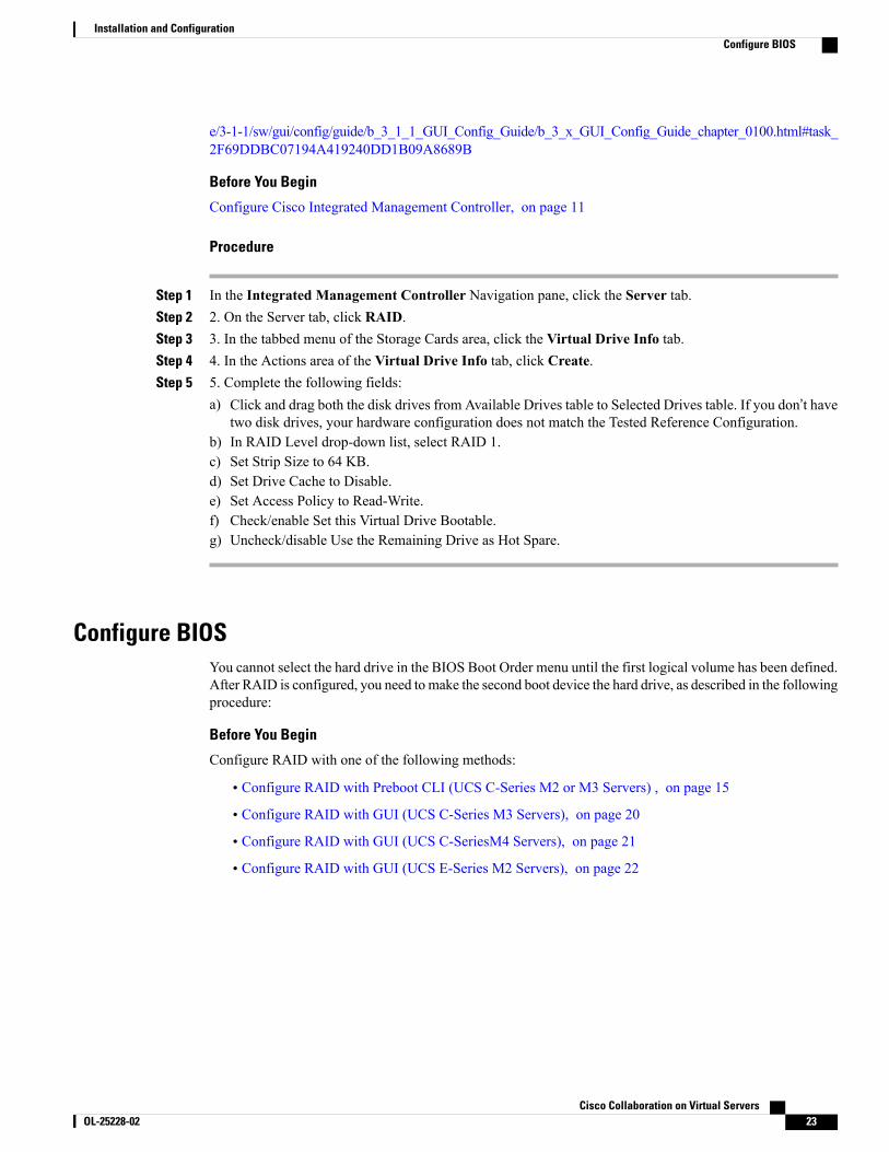
Procedure
Step 1 In the Integrated Management Controller Navigation pane, click the Server tab.Step 2 2. On the Server tab, click RAID.Step 3 3. In the tabbed menu of the Storage Cards area, click the Virtual Drive Info tab.Step 4 4. In the Actions area of the Virtual Drive Info tab, click Create.Step 5 5. Complete the following fields:
a) Click and drag all 3 disk drives from Available Drives table to Selected Drives table. If you don’t havethree disk drives, your hardware configuration does not match the Tested Reference Configuration.
b) In RAID Level drop-down list, select RAID 5.c) Set Strip Size to 64 KB.d) Set Drive Cache to Disable.e) Set Access Policy to Read-Write.f) Check/enable Set this Virtual Drive Bootable.g) Uncheck/disable Use the Remaining Drive as Hot Spare.
Configure RAID with GUI (UCS E-Series M3 Servers)Use this procedure if you have an M3 server and want to configure a RAID 1 Array on a virtual drive.
Configure the UCS E160D M2 for RAID5. At the time of this writing, follow the instructions in the GUIConfiguration Guide for Cisco UCS E-Series Servers and the Cisco UCS E-Series Network Compute EngineIntegrated Management Controller located at http://www.cisco.com/c/en/us/td/docs/unified_computing/ucs/
Cisco Collaboration on Virtual Servers22 OL-25228-02
Installation and ConfigurationRAID Configuration
e/3-1-1/sw/gui/config/guide/b_3_1_1_GUI_Config_Guide/b_3_x_GUI_Config_Guide_chapter_0100.html#task_2F69DDBC07194A419240DD1B09A8689B
Before You Begin
Configure Cisco Integrated Management Controller, on page 11
Procedure
Step 1 In the Integrated Management Controller Navigation pane, click the Server tab.Step 2 2. On the Server tab, click RAID.Step 3 3. In the tabbed menu of the Storage Cards area, click the Virtual Drive Info tab.Step 4 4. In the Actions area of the Virtual Drive Info tab, click Create.Step 5 5. Complete the following fields:
a) Click and drag both the disk drives from Available Drives table to Selected Drives table. If you don’t havetwo disk drives, your hardware configuration does not match the Tested Reference Configuration.
b) In RAID Level drop-down list, select RAID 1.c) Set Strip Size to 64 KB.d) Set Drive Cache to Disable.e) Set Access Policy to Read-Write.f) Check/enable Set this Virtual Drive Bootable.g) Uncheck/disable Use the Remaining Drive as Hot Spare.
Configure BIOSYou cannot select the hard drive in the BIOS Boot Order menu until the first logical volume has been defined.After RAID is configured, you need to make the second boot device the hard drive, as described in the followingprocedure:
Before You Begin
Configure RAID with one of the following methods:
• Configure RAID with Preboot CLI (UCS C-Series M2 or M3 Servers) , on page 15
• Configure RAID with GUI (UCS C-Series M3 Servers), on page 20
• Configure RAID with GUI (UCS C-SeriesM4 Servers), on page 21
• Configure RAID with GUI (UCS E-Series M2 Servers), on page 22
Cisco Collaboration on Virtual Servers OL-25228-02 23
Installation and ConfigurationConfigure BIOS

Procedure
Step 1 Press indicated function key (e.g. F2 for a UCS C-Series) during boot to enter BIOS setup.Step 2 Move the cursor to Boot Options.Step 3 Verify that the CD ROM, or Cisco Virtual CD/DVD (Virtual CD/DVD drive), is selected for Boot Option
#1.Step 4 Verify that the hard drive (the RAID 5 Array) is selected for Boot Option #2.Step 5 Verify that virtual threading is enabled in advanced CPU options.Step 6 Verify that VT I/O Redirection is disabled in the CPU options.
The server will now try to boot the CD ROM drive first and the hard drive second.
What to Do Next
Install and Configure VMware ESXi, on page 24
Install and Configure VMware ESXiThe following sections provide a sequence of steps for bringing ESXi into service at the customer site.
Preparation for ESXi Installation
Before you install ESXi, make sure these tasks are completed:
• The BIOS boot order is configured to boot the CD-ROM or virtual CD/DVD first..
• Each virtual drives on your servers has been configured with a RAID array. For RAID configurationdetails for your, see RAID Configuration, on page 13
For additional information about ESXi storage configurations, see http://docwiki-dev.cisco.com/wiki/UC_Virtualization_Supported_Hardware#Storage.
For servers ordered as Cisco Business Edition 6000 or Cisco Business Edition 7000, these steps have beenperformed by the factory prior to shipping.
Install ESXi
• To determine which ESXi version is required for the application you are intending to deploy, see: http://docwiki.cisco.com/wiki/Unified_Communications_VMWare_Requirements#Supported_Versions_of_VMware_vSphere_ESXi
• Install ESXi on one of the RAID arrays. If there are multiple RAID arrays, any is acceptable but it isrecommended to install ESXi on the first.
You can install ESXi on the first RAID array. It is not required that you install ESXion both arrays.
Note
Cisco Collaboration on Virtual Servers24 OL-25228-02
Installation and ConfigurationInstall and Configure VMware ESXi

• ESXi Installation takes less than 5 minutes. After installation is complete, remove the install CD or thevirtual DVD and reboot the machine.
• Following a reboot, a gray and yellow ESXi console is displayed with 2 options:
◦F2 to customize the system
◦F12 to restart or halt the system
• At this point, press F2 and configure the system in accordance with your network.
Install vSphere Client
Once the host is on the network, you can browse to its IP address to bring up a web-based interface. ThevSphere client is Windows-based, so the download and install must be performed from a Windows PC.
This installation proceeds like any other Windows application installation, and takes only a few minutes toperform. After the vSphere client is installed, you can bring it up and log into the host using the hostname orIP address, the root login ID, and the password configured above.
The host may also be joined to a vCenter if available and if you wish to manage the host through vCenter.
Configuring LAN on Motherboard (LOM) NICs and Virtual Switches
The following options may be configured:
• Simple vSwitch0 (default VMware virtual switch)
• For larger data centers using vCenter, you can configure distributed virtual switches (for example,distributed vSwitch or the Nexus 1000V distributed virtual switch)
• For all options, you must define a port group for each VLAN running on the virtual switch. These portgroups are selected when configuring a Virtual Machine network adapter, to place the virtual machineon a given LAN.
What to Do Next
Download Virtual Machine Templates (OVA Templates), on page 25
Download Virtual Machine Templates (OVA Templates)The configuration of a Cisco Collaboration application virtual machinemust match a supported virtual machinetemplate.
Before You Begin
Install and Configure VMware ESXi, on page 24
Procedure
To download OVAs for Cisco Collaboration applications, go to www.cisco.com/go/uc-virtualized.
What to Do Next
Create the VM for your server type:
Cisco Collaboration on Virtual Servers OL-25228-02 25
Installation and ConfigurationDownload Virtual Machine Templates (OVA Templates)

• Use vSphere to Create the VM for Servers with Optical Drives, on page 26
• Use vSphere to Create the VM for Servers Without Optical Drives, on page 26
ISO and VM Template DeliveryDepending on the servers and virtualization licenses that you purchase, virtualization software and Ciscoapplication software can be delivered either physically or electronically.
Use vSphere to Create the VM for Servers with Optical DrivesCisco provides templates on a URL to download and transfer to a host. Use the following procedure to usevSphere create the VM for servers with optical drives.
Before You Begin
Download Virtual Machine Templates (OVA Templates), on page 25
Procedure
Step 1 Deploy a blank virtual machine from the OVA template for your application using the Cisco.com URL as thesource.
Step 2 Make the CD-ROM drive available to the newly deployed VM.Step 3 Click onOptions >Boot Options the next time the virtual machine boots, force entry into BIOS Setup Screen.Step 4 Insert the application installation DVD from the media kit in the system CD-ROM drive.Step 5 Power on the VM, select Boot and promote CD-ROM to boot before the hard drive.Step 6 Save the BIOS settings and boot.
The installation screens for your application appear at this point.
What to Do Next
Install Cisco Collaboration Applications on VMs, on page 27
Use vSphere to Create the VM for Servers Without Optical DrivesCisco provides templates on a URL to download and transfer to a host. Use the following procedure to usevSphere create the VM for servers without optical drives.
Before You Begin
Download Virtual Machine Templates (OVA Templates), on page 25
Cisco Collaboration on Virtual Servers26 OL-25228-02
Installation and ConfigurationUse vSphere to Create the VM for Servers with Optical Drives

Procedure
Step 1 Deploy a blank virtual machine from the appropriate OVA template for your application using the cisco.comURL as the source.
Step 2 Associate the bootable application installation ISO file with the newly deployed VM.Step 3 Set up the BIOS boot order. For instructions, see the release notes for the OVA that you are deploying.Step 4 Map the ISO-format application installer file from the media kit to the physical or virtual CD/DVD drive..Step 5 Save the BIOS settings and boot.
The normal installation screen for your application opens.
What to Do Next
Install Cisco Collaboration Applications on VMs, on page 27
Install Cisco Collaboration Applications on VMs
Installing Cisco Unified Communications Manager
For details on how to install Cisco Unified CommunicationsManager, refer to the Installation Guide for CiscoUnified Communications Manager at the following URL:
http://www.cisco.com/c/en/us/support/unified-communications/unified-communications-manager-callmanager/products-installation-guides-list.html
Installing Cisco Business Edition 6000
For details on how to install Cisco Business Edition 6000, refer to the Installation Guide for Cisco BusinessEdition 6000 at the following URL:
http://www.cisco.com/go/be6000
Installing Cisco Business Edition 7000
For details on how to install Cisco Business Edition 7000, refer to the Installation Guide for Cisco BusinessEdition 7000 at the following URL:
http://www.cisco.com/go/be7000
Cisco Collaboration on Virtual Servers OL-25228-02 27
Installation and ConfigurationInstall Cisco Collaboration Applications on VMs

Cisco Collaboration on Virtual Servers28 OL-25228-02
Installation and ConfigurationInstall Cisco Collaboration Applications on VMs

C H A P T E R 3Migration
Migration of Collaboration applications from nonvirtual servers to virtualized servers uses different proceduresdepending on whether or not there is also an application version upgrade. For more information, see thefollowing documents.
For 10.x and earlier systems:
• Cisco Prime Collaboration Deployment Administration Guide
• Cisco Unified Communications Operating System Administration Guide
• Disaster Recovery System Administration Guide
• Installing Cisco Unified Communications Manager
• Replacing a Single Server or Cluster for Cisco Unified Communications Manager
• See “Changing the Cluster IP Addresses for Publisher Servers That Are Defined by Host Name” in theChanging the IP Address and Host Name for Cisco Unified Communications Manager guide.
For 11.x and later systems:
• Prime Collaboration Deployment Administration Guide for Cisco Unified Communications Manager
• Administration Guide for Cisco Unified Communications Manager
• Installing Cisco Unified Communications Manager
• Replacing a Single Server or Cluster for Cisco Unified Communications Manager
• Migrate to Cisco UCS B-Series Blade Servers, page 29
• Migrate to Cisco UCS Rack-Mount Server, page 31
• Migrate Cisco Unity Connection on a Virtual Machine, page 33
Migrate to Cisco UCS B-Series Blade ServersMigrating from aMedia Convergence Server (MCS) to a Cisco UCSB-Series Blade Server follows a procedurethat is very similar to replacing server hardware, which is described in the document Replacing a Single Serveror Cluster for Cisco Unified Communications Manager.
Cisco Collaboration on Virtual Servers OL-25228-02 29
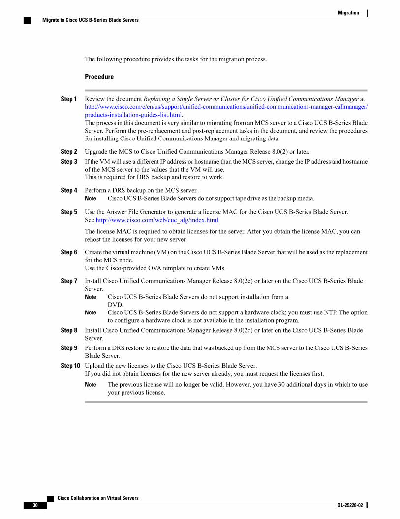
The following procedure provides the tasks for the migration process.
Procedure
Step 1 Review the document Replacing a Single Server or Cluster for Cisco Unified Communications Manager athttp://www.cisco.com/c/en/us/support/unified-communications/unified-communications-manager-callmanager/products-installation-guides-list.html.The process in this document is very similar to migrating from anMCS server to a Cisco UCS B-Series BladeServer. Perform the pre-replacement and post-replacement tasks in the document, and review the proceduresfor installing Cisco Unified Communications Manager and migrating data.
Step 2 Upgrade the MCS to Cisco Unified Communications Manager Release 8.0(2) or later.Step 3 If the VMwill use a different IP address or hostname than theMCS server, change the IP address and hostname
of the MCS server to the values that the VM will use.This is required for DRS backup and restore to work.
Step 4 Perform a DRS backup on the MCS server.Cisco UCSB-Series Blade Servers do not support tape drive as the backupmedia.Note
Step 5 Use the Answer File Generator to generate a license MAC for the Cisco UCS B-Series Blade Server.See http://www.cisco.com/web/cuc_afg/index.html.
The license MAC is required to obtain licenses for the server. After you obtain the license MAC, you canrehost the licenses for your new server.
Step 6 Create the virtual machine (VM) on the Cisco UCS B-Series Blade Server that will be used as the replacementfor the MCS node.Use the Cisco-provided OVA template to create VMs.
Step 7 Install Cisco Unified Communications Manager Release 8.0(2c) or later on the Cisco UCS B-Series BladeServer.
Cisco UCS B-Series Blade Servers do not support installation from aDVD.
Note
Cisco UCS B-Series Blade Servers do not support a hardware clock; you must use NTP. The optionto configure a hardware clock is not available in the installation program.
Note
Step 8 Install Cisco Unified Communications Manager Release 8.0(2c) or later on the Cisco UCS B-Series BladeServer.
Step 9 Perform a DRS restore to restore the data that was backed up from the MCS server to the Cisco UCS B-SeriesBlade Server.
Step 10 Upload the new licenses to the Cisco UCS B-Series Blade Server.If you did not obtain licenses for the new server already, you must request the licenses first.
The previous license will no longer be valid. However, you have 30 additional days in which to useyour previous license.
Note
Cisco Collaboration on Virtual Servers30 OL-25228-02
MigrationMigrate to Cisco UCS B-Series Blade Servers

Migrate to Cisco UCS Rack-Mount ServerMigrating from a Media Convergence Server (MCS server) to a Cisco UCS Rack-Mount Server follows aprocedure that is very similar to replacing server hardware, which is described in the document Replacing aSingle Server or Cluster for Cisco Unified Communications Manager.
The following table provides an overview of the migration process and references to other pertinentdocumentation.
Related procedures and topicsConfiguration stepsSteps
Replacing a Single Server orCluster for Cisco UnifiedCommunications Manager
Review the document Replacing a Single Server orCluster for Cisco Unified Communications Manager.This document describes how to replace server hardware,which is very similar to migrating from an MCS serverto a CiscoUCSRack-Mount Server. You should performthe document’s pre-replacement and post-replacementtasks, and review the procedures for installing CiscoUnified Communications Manager and migrating data.
Step 1
For 8.x-10.x:
• Cisco UnifiedCommunicationsOperatingSystem AdministrationGuide
For 11.x:
• Administration Guide forCisco UnifiedCommunications Manager
Upgrade the MCS server to Cisco UnifiedCommunications Manager Release 8.0(2) or later.
Step 2
Refer to the topic “Changing theCluster IP Addresses forPublisher Servers That AreDefined by Host Name” in theChanging the IP Address andHost Name for Cisco UnifiedCommunicationsManager guide.
If the VM will use a different IP address or hostnamethan the MCS server, change the IP address andhostname of the MCS server to the values that the VMwill use.
This is required for DRS backup and restore to work.
Step 3
For 8.x-10.x:
• Disaster Recovery SystemAdministration Guide
For 11.x:
• Administration Guide forCisco UnifiedCommunications Manager
Perform a DRS backup on the MCS server.Step 4
Cisco Collaboration on Virtual Servers OL-25228-02 31
MigrationMigrate to Cisco UCS Rack-Mount Server
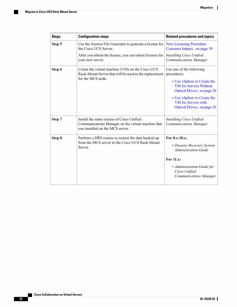
Related procedures and topicsConfiguration stepsSteps
New Licensing ProcedureCustomer Impact, on page 39
Installing Cisco UnifiedCommunications Manager
Use the Answer File Generator to generate a license forthe Cisco UCS Server.
After you obtain the license, you can rehost licenses foryour new server.
Step 5
Use one of the followingprocedures:
• Use vSphere to Create theVM for Servers WithoutOptical Drives, on page 26
• Use vSphere to Create theVM for Servers withOptical Drives, on page 26
Create the virtual machine (VM) on the Cisco UCSRack-Mount Server that will be used as the replacementfor the MCS node.
Step 6
Installing Cisco UnifiedCommunications Manager
Install the same release of Cisco UnifiedCommunications Manager on the virtual machine thatyou installed on the MCS server.
Step 7
For 8.x-10.x:
• Disaster Recovery SystemAdministration Guide
For 11.x:
• Administration Guide forCisco UnifiedCommunications Manager
Perform a DRS restore to restore the data backed upfrom the MCS server to the Cisco UCS Rack-MountServer.
Step 8
Cisco Collaboration on Virtual Servers32 OL-25228-02
MigrationMigrate to Cisco UCS Rack-Mount Server

Related procedures and topicsConfiguration stepsSteps
New Licensing ProcedureCustomer Impact, on page 39
Administration Guide for CiscoUnified CommunicationsManager
For 8.x-10.x:
• Cisco UnifiedCommunicationsOperatingSystem AdministrationGuide
• Enterprise LicenseManager User Guide
• Cisco Prime LicenseManager User Guide
For 11.x:
• Administration Guide forCisco UnifiedCommunications Manager
Upload the licenses that you generated to:
• For 8.x systems—publisher node
• For 9.x systems—Enterprise License Manager
• 10.x and up—Cisco Prime License Manager
If you did not obtain licenses for the new server already,you must request the licenses first.
The previous license will no longer be valid.However, you have 30 additional days in whichto use your previous license. See NewLicensing Procedure Customer Impact, on page39.
Note
Step 9
Migrate Cisco Unity Connection on a Virtual MachineFor information on migrating to Cisco Unity Connection on a virtual machine, see the “Migrating from aCisco Unity Connection Physical Server to a Connection 8.x Virtual Machine” chapter in the applicableReconfiguration and Upgrade Guide for Cisco Unity Connection at http://www.cisco.com/en/US/products/ps6509/prod_installation_guides_list.html.
Cisco and the Cisco Logo are trademarks of Cisco Systems, Inc. and/or its affiliates in the U.S. and othercountries. A listing of Cisco's trademarks can be found at www.cisco.com/go/trademarks. Third party trademarksmentioned are the property of their respective owners. The use of the word partner does not imply a partnershiprelationship between Cisco and any other company. (1005R)
Cisco Collaboration on Virtual Servers OL-25228-02 33
MigrationMigrate Cisco Unity Connection on a Virtual Machine

Cisco Collaboration on Virtual Servers34 OL-25228-02
MigrationMigrate Cisco Unity Connection on a Virtual Machine
C H A P T E R 4Administration
• Rack-Mount Server Daily Operations, page 35
• Monitoring From Virtual Machine, page 36
• Monitoring From Cisco Integrated Management Controller, page 36
• Monitoring From vSphere Client and vCenter, page 36
• Server Health Monitoring From ESXi, page 36
• Disk Management for Cisco UCS Rack-Mount Servers, page 36
• Automatic Update Statistics, page 37
• New Identity, page 37
• Licensing Cisco Unified CM on Virtualized Servers, page 38
• Related Documentation, page 40
Rack-Mount Server Daily OperationsAt this point the application is installed and in operation. Daily operations for applications are similar to aninstallation on a physical server, including:
• Application configuration and integration with other applications
• RTMT performance monitoring
• SNMP monitoring and alarms
• DRS backup and restore
• CDR collection
• Device, trunk, gateway configuration and monitoring
Cisco Collaboration on Virtual Servers OL-25228-02 35

Monitoring From Virtual MachineApplications running in a VM have no ability to monitor the physical hardware. Any hardware monitoringmust be done from the Cisco Integrated Management Controller, ESXi plugins, vCenter or by physicalinspection (for flashing LEDs, and so on).
Monitoring of hardware is the customer's responsibility. It is assumed the customer is familiar with virtualizedenvironments and knows how to manage hardware in these environments.
Monitoring From Cisco Integrated Management ControllerThe Cisco Integrated Management Controller (Cisco IMC) provides the following hardware monitoring:
• An overview of CPU, memory, and power supply health
• An overview of hardware inventory, including CPUs, Memory, Power Supplies, and Storage
• Monitoring of sensors for Power Supplies, Fans, Temperature, Voltage, and Current
• A system event log that contains BIOS and Sensor entries
• LSI MegaRAID controller information, which includes physical and virtual drive layout and BatteryBackup Unit information from the Inventory > Storage tab. This information was usually accessible forearlier UCS servers only by installing the MegaRAID plugin from ESXi.
For additional details, go to www.cisco.com/go/ucs .
Monitoring From vSphere Client and vCenterThe vSphere Client provides the following monitoring:
• Hardware and system alarms defined under the Alarms tab in the vSphere Client when logged in tovCenter.
• VM resource usage under the VirtualMachines tab in the vSphere Client, as well as under the Performancetab for each VM.
• Host performance and resource usage under the Performance tab for the host.
For more information, go to http://www.VMware.com.
Server Health Monitoring From ESXiYou can monitor server health from ESXi by logging into the ESXi console and inspecting system/var/log/messages for telltale entries.
Disk Management for Cisco UCS Rack-Mount ServersFor details on the drive specifications for your Cisco UCS server, refer to RAID Configuration, on page 13.
Cisco Collaboration on Virtual Servers36 OL-25228-02
AdministrationMonitoring From Virtual Machine

Disks are hot-swappable. This does not mean that you will be able to swap drives ad-hoc after a failure. Aprocess exists to swap drives. When a drive fails, you need to follow these steps:
If you have an M4 server, refer to http://www.cisco.com/c/en/us/td/docs/unified_computing/ucs/c/hw/C240M4/install/C240M4.pdf.
Note
1 Reboot and enter the Preboot CLI.
2 Mark the defective drive for removal using -PdPrpRmv -physdrv [<encl>:<slot>] -a0.
3 Replace the drive.
The RAID array is rebuilt automatically when the replacement disk is inserted.
Although Preboot CLI is recommended, you can also perform this task through the LSI MegaRaid GUI,where you can swap drives out without having to power-cycle the server to get into the preboot CLI.However, this method requires you to procure a separate machine (Windows or Linux) on the same subnetas the ESXi host, installed with the LSI MegaRaid utility.
Note
Automatic Update StatisticsCommunicationsManager uses Automatic Update Statistics, an intelligent statistics update feature that monitorsthe changes made in the database tables and updates only tables that need statistic updates. This feature savesconsiderable bandwidth, especially on VMware deployments of CommunicationsManager. Automatic UpdateStatistics is the default indexing method.
For more information about database services, see the Cisco Unified Serviceability Administration Guide.
New IdentityCisco supports the New Identity process for use with Cisco Unified Communications Manager. The NewIdentity process is designed to start with a Communications Manager application that is fully installed andconfigured with common settings. Often, the initial VM is saved as a VMware template and cloned as newCommunications Manager publisher nodes come online.
The New Identity process copies the VMware template and changes a set of primary settings, such as the IPaddress and hostname, to give a new VM a unique identity in the network.
Run New Identity Process
Procedure
Step 1 Create a new VM instance from the template of the deployed Unified CM application.Step 2 Run the CLI command utils import config.
Cisco Collaboration on Virtual Servers OL-25228-02 37
AdministrationAutomatic Update Statistics

For more information about CLI commands, see the documentation at http://www.cisco.com/en/US/docs/voice_ip_comm/cucm/cli_ref/8_5_1/cli_ref_851.html.
New Identity CaveatsWhen you run the New Identity process, note the following:
• Although you can provide a new OS administrator user ID in the XML file, you cannot change the OSadministrator user ID during the New Identity process.
• Each cloned VM has the same network configuration as the VMware template. The network must befunctional during the New Identity process. If you run the cloned VMs on the same LAN there can beduplicate IP addresses. Ensure that you do not run the VMware template, or multiple VMs from theinitial template, at the same time on the same LAN.
• The NTP server must be accessible before you can configure it on the Unified CM application. Ensurethat the VM has access to the new NTP server.
• If DNS is used, DNS servers must be accessible when you run the New Identity process.
• For Cisco Unity Connection, you must set the SMTP domain address after you run the New Identityprocess.
• For Cisco Unified Presence, you must set the postinstallation steps that configure the Unified CM systemwith which Cisco Unified Presence communicates after you run the New Identity process.
Deploy Cluster Nodes Using Templates
Procedure
Step 1 Perform a skip install.Step 2 When prompted for the floppy/USB drive in the Pre-existing Configuration Information window, power
down the VM.Step 3 Clone or convert the VM into a VM template.Step 4 For a new node, deploy the template and mount a virtual floppy drive that contains the configuration file from
the AFG tool.
Licensing Cisco Unified CM on Virtualized Servers
For more information about licensing of your operating system, see http://www.vmware.com.Note
Cisco Collaboration on Virtual Servers38 OL-25228-02
AdministrationNew Identity Caveats
New Licensing Procedure Customer Impact
Licensing for 10.x and up
CiscoUnified CommunicationsManager on Virtual Servers in Release 10.x uses Cisco Prime LicenseManager.For more information, see http://www.cisco.com/en/us/products/sw/voicesw/ps556/prod_maintenance_guides_list.html.
Licensing for 9.X
Cisco Unified Communications Manager on Virtual Servers in Release 9.x uses Enterprise License Manager.For more information, see the Enterprise LicenseManager User Guide at http://www.cisco.com/en/us/products/sw/voicesw/ps556/prod_maintenance_guides_list.html.
Licensing for 8.x
Cisco Unified Communications Manager on Virtual Servers in Release 8.x uses a different licensing modelthan Cisco Unified Communications Manager on non-virtualized servers (including 7800 Series MediaConvergence Servers). The MAC address of the physical NIC card is no longer used to associate the licenseto the server.
The license is associated to a license MAC, which is a 12 digit HEX value created by hashing the followingparameters that you configure on the server:
• Time zone
• NTP server 1 (or “none”)
• NIC speed (or “auto”)
• Hostname
• IP Address (or “dhcp”)
• IP Mask (or “dhcp”)
• Gateway Address (or “dhcp”)
• Primary DNS (or “dhcp”)
• SMTP server (or “none”)
• Certificate Information (Organization, Unit, Location, State, Country)
The ways to obtain the license MAC are as follows:
• Before installation, use the Answer File Generator (http://www.cisco.com/web/cuc_afg/index.html).When you generate the answer file, you also get the license MAC.
If you use this method, ensure that you enter the identical parameter values in the AnswerFile Generator and the Cisco Unified Communications Manager installation program,or the license will be invalid.
Note
• After installation, navigate to Show > System in CiscoUnified CommunicationsManager Administration.
Cisco Collaboration on Virtual Servers OL-25228-02 39
AdministrationNew Licensing Procedure Customer Impact

• After installation, use the CLI command show status.
Obtaining New Licenses
The process to redeem a Product Activation Key (PAK) for licenses at www.cisco.com/go/license is changedfor a license MAC. When redeeming a PAK for a license MAC at this URL, you are prompted to select thetype of license that you want to obtain:
• A physical MAC address—used when Cisco Unified Communications Manager will be installed on anMCS server.
• A licenseMAC address—used when Cisco Unified CommunicationsManager will be installed on CiscoUnified Communications Manager on Virtualized Servers.
After you make this selection, the generation and installation of the license file follows the same process.
Obtaining Rehosted Licenses When You Change License MAC Parameters
When you change any of the parameters that create the license MAC, the license that you obtained with itbecomes invalid. Youmust request a rehosting of the license to obtain a valid license. The old license continuesto work for a 30-day grace period.
To rehost your licenses, you must open a case with the licensing team to obtain a license for your replacementserver. Contact the licensing team at [email protected].
During the grace period, you can change the settings back to the licensed values to make your original licensevalid again. If you need more than 30 days of grace period, change your settings back to the licensed values,and then change them back to the new values that you want to use. You will get another 30-day grace period.
Virtual Machine Setup and Licensing SupportThe virtual machine configuration for running Cisco Unified CommunicationsManager on Virtualized Serversmust match the stated specifications to get support from Cisco.
While Cisco Unified Communications Manager can be installed and licensed in other virtual machineconfigurations, Cisco does not support these configurations.
Related Documentation• The UCS RAID Controller SMI-S Reference Guide, which describes Storage Management InitiativeSpecification (SMI-S) support in the Cisco UCS Servers, is available at the following URL:
http://www.cisco.com/en/US/docs/unified_computing/ucs/sw/utilities/raid/reference/guide/ucs_raid_smis_reference.html
• The official list of supported servers for Cisco Unified Communications Manager releases is availableat the following URL:
http://www.cisco.com/go/uc-virtualized
• Technical specifications of Cisco Unified Communications virtualized servers are available at thefollowing URL:
http://www.cisco.com/go/uc-virtualized
Cisco Collaboration on Virtual Servers40 OL-25228-02
AdministrationVirtual Machine Setup and Licensing Support

• TCP and UDP ports for vCenter Server, ESX hosts, and other management access for other networkcomponents are listed in article 1012382 at the following URL:
http://kb.vmware.com
• The Cisco Unified Communications Virtualization docwiki, which discusses deployment of other CiscoUnified Communications products on virtualized servers, is available at the following URL:
http://www.cisco.com/go/uc-virtualized
Cisco Collaboration on Virtual Servers OL-25228-02 41
AdministrationRelated Documentation

Cisco Collaboration on Virtual Servers42 OL-25228-02
AdministrationRelated Documentation
Top Related