


Languages
Pages
Legal

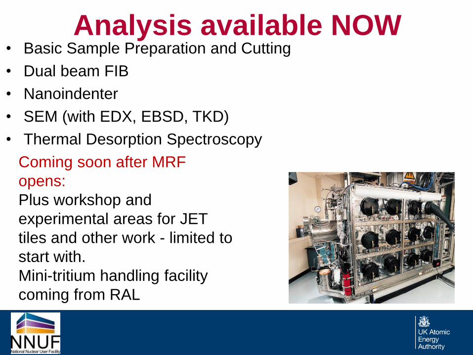
Analysis available NOW • Basic Sample Preparation and Cutting
• Dual beam FIB
• Nanoindenter
• SEM (with EDX, EBSD, TKD)
• Thermal Desorption Spectroscopy
Coming soon after MRF
opens:
Plus workshop and
experimental areas for JET
tiles and other work - limited to
start with.
Mini-tritium handling facility
coming from RAL
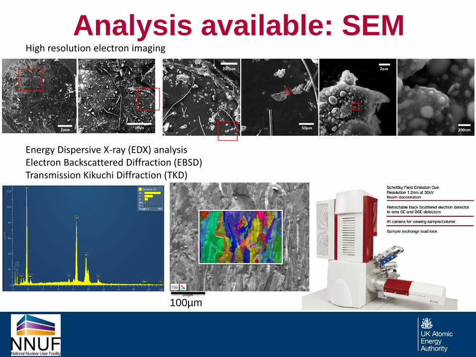
Analysis available: SEM High resolution electron imaging Energy Dispersive X-ray (EDX) analysis Electron Backscattered Diffraction (EBSD) Transmission Kikuchi Diffraction (TKD)
100µm
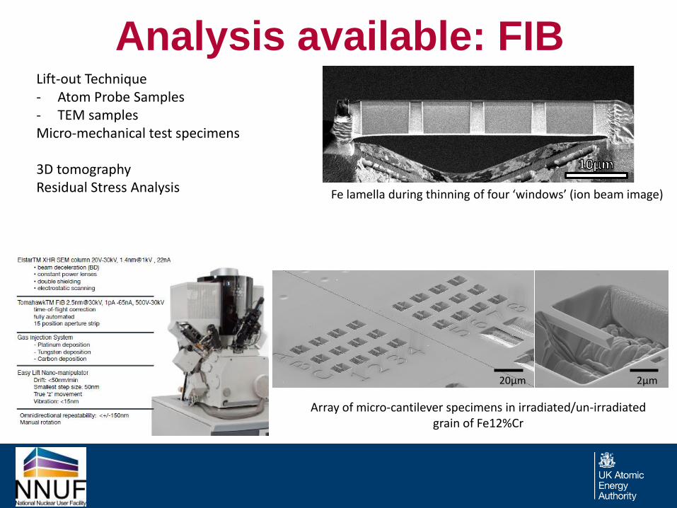
Analysis available: FIB
Fe lamella during thinning of four ‘windows’ (ion beam image)
Lift-out Technique - Atom Probe Samples - TEM samples Micro-mechanical test specimens 3D tomography Residual Stress Analysis
20µm 2µm
Array of micro-cantilever specimens in irradiated/un-irradiated grain of Fe12%Cr
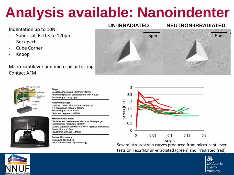
Analysis available: Nanoindenter Indentation up to 10N: - Spherical: R=0.3 to 120µm - Berkovich - Cube Corner - Knoop
Micro-cantilever and micro-pillar testing Contact AFM
0
0.5
1
1.5
2
2.5
3
0 0.05 0.1 0.15 0.2
Stre
ss (
GP
a)
Strain Several stress-strain curves produced from micro-cantilever tests on Fe12%Cr un-irradiated (green) and irradiated (red).
5µm
UN-IRRADIATED NEUTRON-IRRADIATED
5µm
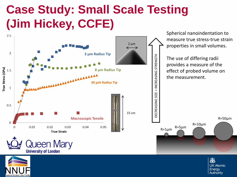
Case Study: Small Scale Testing
(Jim Hickey, CCFE)
15 cm
DEC
REA
SIN
G S
IZE
= IN
CR
EASI
NG
STR
ENG
TH
2 µm
3 µm Radius Tip
8 µm Radius Tip
30 µm Radius Tip
Macroscopic Tensile
R=1µm R=5µm
R=10µm
R=50µm
Spherical nanoindentation to measure true stress-true strain properties in small volumes. The use of differing radii provides a measure of the effect of probed volume on the measurement.
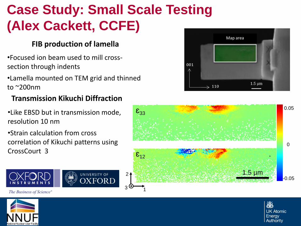
Case Study: Small Scale Testing
(Alex Cackett, CCFE)
Transmission Kikuchi Diffraction
•Like EBSD but in transmission mode, resolution 10 nm
•Strain calculation from cross correlation of Kikuchi patterns using CrossCourt 3
FIB production of lamella
•Focused ion beam used to mill cross-section through indents
•Lamella mounted on TEM grid and thinned to ~200nm
0.05
-0.05
0
ɛ33
ɛ12
1.5 µm
Map area
1
2
3
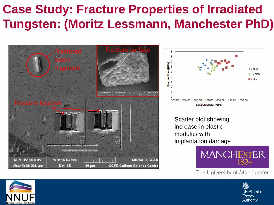
Case Study: Fracture Properties of Irradiated
Tungsten: (Moritz Lessmann, Manchester PhD)
Scatter plot showing
increase in elastic
modulus with
implantation damage
Fractured beam fragment
Fracture location
Fracture surface
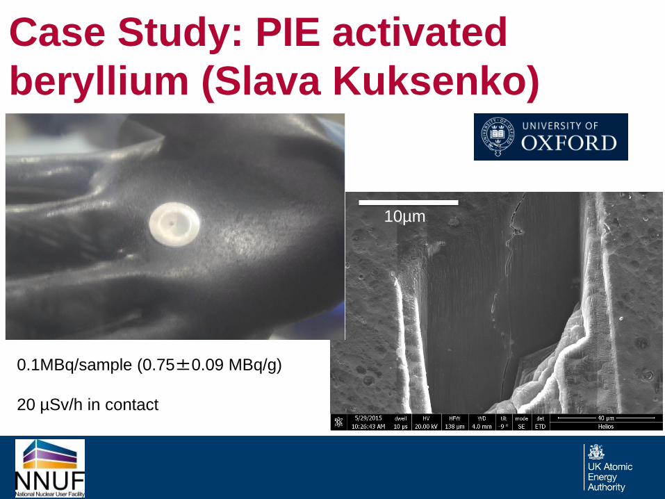
Case Study: PIE activated
beryllium (Slava Kuksenko)
10µm
0.1MBq/sample (0.75±0.09 MBq/g)
20 µSv/h in contact
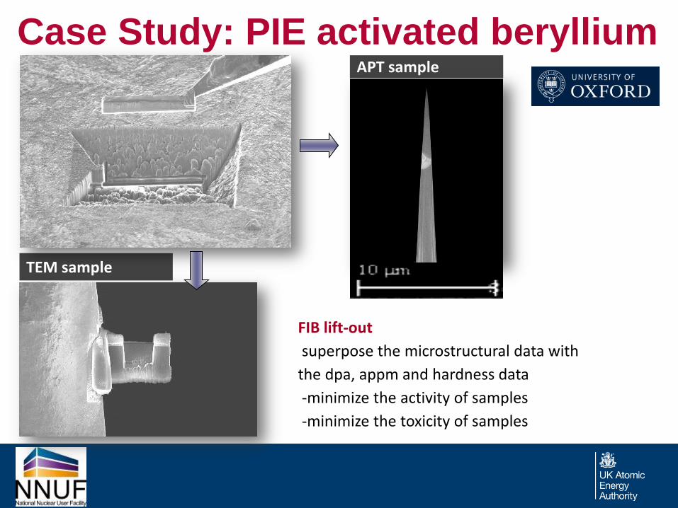
Case Study: PIE activated beryllium APT sample
TEM sample
FIB lift-out
superpose the microstructural data with
the dpa, appm and hardness data
-minimize the activity of samples
-minimize the toxicity of samples
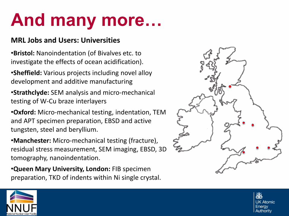
And many more… MRL Jobs and Users: Universities
•Bristol: Nanoindentation (of Bivalves etc. to investigate the effects of ocean acidification).
•Sheffield: Various projects including novel alloy development and additive manufacturing
•Strathclyde: SEM analysis and micro-mechanical testing of W-Cu braze interlayers
•Oxford: Micro-mechanical testing, indentation, TEM and APT specimen preparation, EBSD and active tungsten, steel and beryllium.
•Manchester: Micro-mechanical testing (fracture), residual stress measurement, SEM imaging, EBSD, 3D tomography, nanoindentation.
•Queen Mary University, London: FIB specimen preparation, TKD of indents within Ni single crystal.
And many more… MRL Jobs and Users: Industry
•UKAEA (MASTU): Braze composition analysis, 316SS phase analysis EBSD.
•UKAEA (JET): SEM/EDX/EBSD tie rod failure analysis, SEM/EDX JET Dust analysis, bolt testing fractography, EBSD of additive manufactured Inconel 718, SEM-EDX investigation of anomalous flywheel wearing
•UKAEA (Special Techniques Group): EDX braze filler identification, furnace contamination analysis
•ISIS Innovation: SEM imaging and EDX chemical analysis of electrode erosion
•Reaction Engines: Sample preparation for cross-sectioning miniature thin walled tubes, FIB surface preparation, SEM/EDX of nickel super alloy tubes, SEM analysis of HIP titanium components
•CEA, France: Micro-mechanical testing of Eurofer and ODS Eurofer, FIB specimen prep and nanoindentation
•AMECFW: Nanoindentation of Be-CuCrZr braze interlayer and parent materials.
Future capabilities in the MRF:
• The MRF is a user facility
– This means that the MRF must cater for the needs of
academia and industry
– Sustainability of the MRF relies on its users
• Investment in the future instrumentation and capability of the
MRF must represent the greatest demand from users.
• The MRF requires your input into making the best use of
future investment into extending capability… after lunch…!

Thank you
Top Related