


Languages
Pages
Legal


1
UNIT - 1
ELECTOCHEMISTRY AND CORROSION
Introduction
Electrochemistry is the branch of chemistry which deals with the transformation of electrical
energy to chemical energy and vice versa. In brief it deals with the chemical applications of
electricity.
Electric current is a flow of electrons generated by a battery, when the circuit is completed.
Electrolysis is one process where electrical energy causes chemical changes. It is carried out
in an apparatus called electrolytic cell. The cell contains electrolyte and electrodes. The
electrode connected to the positive pole of the current source is called anode. The electrode
connected to the negative pole of the current source is called cathode. When an electric
current is passed through the electrolytic solution, cations move towards cathode (-ve
electrode and anions move towards anode (+ve electrode)
Ex: Electrolysis of water yields H2 and O2
In other process, certain chemical reactions takes place in a vessel and produce electric
energy. The device is called electrochemical cell. Eg. Galvanic cell, batteries and fuel cells
Broadly we can classify the cells as electrolytic cells and electrochemical cells.
Electrolytic cell: A device which converts electrical energy to chemical energy
Electrochemical cell: A device which converts chemical energy to electrical energy
Types of Conductors:
Substances which allow electric current to pass through them are known as electrical
conductors. Eg. All metals, graphite, fused salts, aqueous solutions of acids and bases and
salts.
Substances which partially conduct electricity are known as semi-conductors.Eg: Silicon,
Germanium.
Substances which do not allow electricity to pass through them are known as non-conductors
or insulators. Eg. Rubber, wood, paper, all non-metals except carbon
Conductance: The capacity of a conductor to allow the passage of current through it called
conductance.
Conductance (C) = 1
𝑅
Electrical Energy Chemical Energy

2
i.e. The reciprocal of resistance is called conductance.
Units: Ohm.-1
Conductor: The substance which allows the passage of electric current through it is called
conductors. E.g.:- all metals, graphite, aqueous solution of acids and bases.
Electric conductors are two types
1. Metallic conductors: They conduct electricity by free electrons, mobile, valance electrons
and involve flow of electrons.There is no chemical decomposition during conductance. E.g.;
metals, alloys, certain solid salts and oxides.
2. Electrolytic conductors: The substance which allows the electricity to pass-through them
in their molten state or in their aqueous solution are called electrolytic conductors or
electrolytes. They undergo chemical decomposition.
Eg: Acids and bases.
Non-Electrolytes: Non-Electrolytes do not dissociate into ions even at low dilutions.
Eg: Glucose,Sugar.
Electrolytes are classified into two types:
Strong electrolytes: The electrolytes which completely dissociates in solution at all
concentrations. Their conductance is very high. Eg. NaCl, HCl, NaOH.
Weak Electrolytes: The electrolyte which partially dissociates at moderate concentration.
Their conductance is low as they dissociate only to a small extent even at very high dilutions.
Eg: CH3COOH, NH4OH, sparingly soluble salts like AgCl, AgBr, AgI, BaSO4, PbSO4 etc
Differences between metallic conductors and electrolytic conductors:
Metallic conductor
Electrolytic conductors
Conductance due to the migration of
electrons.
E.g.: metals, graphite.
Conductance due to the migration of ions
in a solution of fused electrolyte.
E.g.: Acids and bases
Passage of current due to electron flow.No
chemical reaction takes place.
Passage of current due to movement of
ions. Some chemical reaction takes place.
Free electrons are responsible for electrical
conduction.
Free ions are responsible for electrical
conduction.
Mass is not transferred Mass is transferred.
With increase of temp resistance
increasesand conductance decreases
With increase of temperature resistance
decreases and conductance increases.

3
CONDUCTANCE:
Ohm’s Law: Ohm‟s law states that the current (I) flowing through a conductor is directly
proportional to potential difference (E) applied across the conductor and is inversely
proportional to the resistance of conductor.
Thus,
Where I is the current in amperes, and E is potential difference applied across the conductor
in volts.
Thus
or
Where R is the proportionality constant and is known as the resistance of conductor in ohms.
Thus, the resistance of a conductor is directly proportional to the potential difference applied
across the conductor and inversely proportional to the current carried by the conductor.
SPECIFIC RESISTANCE:The resistance of a uniform conductor is directly proportional to
its length (l) and inversely proportional to the area of the cross- section (a).Thus
The proportionality constant (ρ) is called as the specific resistance of an electrolytic solution
of 1cm in length and 1cm2 area of cross section. i.e. resistance of 1cm
3 of the electrolytic
solution.
UNITS: specific resistance units: Ohm Cm
Specific conductance: The reciprocal of specific resistance (ρ) is called as specific
conductance. This may be defined as the conductance of 1cm3 of a material and denoted by K
(kappa). Thus
But 𝜌 = R × a
l (∵ R =𝜌 ×
𝑙
𝑎 ) ∴
E α I
E=IR
R=E
I
R α l/a
R=ρl/a
K =1
𝜌
K= 1
𝑅×
l
a

4
Units: Ohms-1
Cm.-1
Equivalence Conductance:
If one gram equivalent weight of an electrolyte is dissolved in Vml of the solvent, the
conductivity of all ions produced from one gram equivalent of an electrolyte at the
dilution V is known as equivalent conductance. This is denoted by the symbol λeq.
V = volume of electrolytic solution in milliliters containing 1g equivalent wt of an electrolyte
Let C be the concentration of a solution containing gm equivalent of electrolyte per liter and
the volume V of the solution will be 1000/C.
Units: ohm-1
cm2eq
-1 or Scm
2eq
-1
Molar conductance: Molar conductance is defined as the conductance of an electrolyte
solution containing 1 mol of an electrolyte. It is denoted by λm. If Vml is the volume of
solution containing 1 g mol of the electrolyte,
UNITS: ohm-1
cm2
mol-1
Cell constant:
It is a constant, characteristic of the cell in which the electrolyte is taken and its value
depends on the distance between the electrodes and area of cross-section of the electrodes.
λeq=K×V
λeq= K×1000
N
λeq =𝑘×1000
𝑁.
λm = K × Vm
λm= 𝐾×1000
𝑀
V=1000
𝑀=
1000
𝑀𝑜𝑙𝑎𝑟𝑖𝑡𝑦 𝑜𝑓 𝑡ℎ𝑒 𝑒𝑙𝑒𝑐𝑡𝑟𝑜𝑙𝑦𝑡𝑒 𝑠𝑜𝑙𝑢𝑡𝑖𝑜𝑛 .
V = 1000
C=
1000
𝑁𝑜𝑟𝑚𝑎𝑙𝑖𝑡𝑦 𝑜𝑓 𝑡ℎ𝑒 𝑒𝑙𝑒𝑐𝑡𝑟𝑜𝑙𝑦𝑡𝑒 𝑠𝑜𝑙𝑢𝑡𝑖𝑜𝑛 .
Cell constat =Distance between the electrodes
Area of cross − section of each electrode

5
And specific conductance, K =1
R×
l
a
∴ Specific conductance = Cellconstant
R
If area of cross-section is in cm2 and distance between the electrodes is in cm, the unit of cell
constant is cm-1
.
Effect of dilution on conductance:
Since conductivity of a solution is due to the presence of ions in solution, greater the number
of ions in a solution greater will be its conductivity. As the dilution increases more and more,
the electrolyte ionizes more and more i.e ionization increase, the conductivity of the solution
also increases on dilution. Hence dilution of solution is directly proportional to its
conductivity. Dilution ∝ conductance
Effect of dilution on Specific conductance: On dilution, the volume of electrolyte solution
increases. Thus, the number of ions present in one centimeter cube of the solution is
decreased. Hence, the specific conductance decreases on progressive dilution. Hence, dilution
is inversely proportional to specific conductance. Dilution ∝ 1/K
Effect of dilution on Equivalent conductance and molar conductance:
Equivalent and molar conductance of an electrolyte increases on dilution because
ionization increases on dilution
On dilution, the concentration of electrolyte decreases and the retarding influence of
charged ions decreases. So speed of ions increases and hence equivalent and molar
conductance increases.
The equivalent and molar conductance increases with dilution because these are the
products of specific conductance and volume of the solution containing 1 g equivalent of
the electrolyte. (λeq= K x V). Hence they are directly proportional to volume. On dilution
volume of electrolytic solution increase and therefore equivalent and molar conductance
increases with dilution.
FACTORS INFLUENCING THE MAGNITUDE OF CONDUCTANCE OF AN
ELECTROLYTIC SOLUTION:
1. Nature of electrolyte: A strong electrolyte which ionizes completely has a large
conductance while a weak electrolyte which partially ionises has low conductance.
or 𝑥 = 𝐾 × 𝑅; or 𝑥 =𝐾
𝐶 ( ∵ 𝑐 = 1/𝑅)
𝒙 =𝒍
𝒂

6
2. Concentration of electrolyte: Ifan electrolyte is diluted, the extent of ionization
increases and large number of ions are produced and hence equivalent conductance
increases withdilution.
3. Temperature:Conductance increases with increase in temperature. At higher
temperature the mobility of ions is increased and hencethe conductivity increases.
4. Size of ions: Increase in the size of ions increases ionic interaction due to solvation
and decreases the conductance.
5. Inter-ionic forces: Increase in interionic forces will inhibit the movement of ions and
the conductance of the electrolyte decreases.
6. Nature of solvent: Viscous medium restricts the movement of ions and hence the
conductivity is reduced.
APPLICATIONS OF CONDUCTANCE:
CONDUTOMETRIC TITRATIONS: Titrations involving conductivity measurements of
electrolytes to get endpoint are called conductometric titrations. The end point is generally
found out by plotting the conductance values on y-axis against the volume of electrolyte on
x-axis. The electrical conductance of an aqueous solution depends up on:
1. The number of free ions in the solution containing an electrolyte.
2. The charge on the free ions.
3. The mobility of the ions.
1. Strong acid Vs Strong base titrations:
In an acid–base titration, acid is taken in the conical flask and base is added through the
burette. Consider the titration of strong acid (HCl) with strong base (NaOH). Before the
addition of NaOH, the conductivity is mainly due to the H+ ions; hence the conductivity is
high. On the gradual addition of NaOH from the burette, the fast moving H+
ions of acid are
replaced by OH-
ions. The conductivity of the solution decreases progressively by the
addition of NaOH till the equivalence point is reached. The conductance again increases after
the equivalence point.
𝐻𝐶𝑙 + 𝑁𝑎𝑂𝐻 →NaCl + H2O

7
2. Weak acid Vs Strong basetitration:
When weak acid is titrated with strong base, the conductance of the solution is low in the
beginning, since the dissociation of weak acid is very low. On addition of base, highly
dissociated sodium acetate is formed.Due to the common ion effect, the acetate ion tends to
suppress the ionization of acetic acid. Later the conductivity begins to increase due to the
conductivity power of the highly ionized salt exceeds that of weak acid.After end point, the
addition of NaOH contributes sharp increase in the conductivity of the solution. The point of
intersection of the two cures gives the end point of the titration.
CH3COOH + NaOH→ CH3COONa + H2O
3. Strong acid Vs weak base titrations: When strong acid is titrated against a weak
base, the conductance of the solution first decrease due to the replacement of fast moving H+
ions with slow moving NH4+ions. After the end point, the addition of excess of NH4OH will
not result in any appreciable change in the conductivity.
HCl + NH4OH → NH4Cl + H2O

8
4. Weak acid Vs weak base Titration:Consider the titration of acetic acid against
ammonium hydroxide. The titration of weak acid with weak base does not give sharp end
point by volumetric titrations. The initial conductance of the solution is low due to the poor
dissociation of weak acid, but starts raising as CH3COONH4is formed. After the equivalent
point, the conductivity remains almost constant because the free base NH4OH is weak
electrolyte. The end point is quite sharp by conductometric titrations
CH3COOH + NH4OH → CH3 COONH4 + H2O
5. Precipitation titrations: In precipitation titrations, sharp endpoint is obtained, e.g.
The titration of KCl against AgNO3. There is no sharp increase in conductance after the
addition of AgNO3, because the mobility of K+ and Ag
+ is one and the same. After the end
point, there is a sharp increase in conductance due to an increase in the number of free ions in
the solution.
KCl + AgNO3→ KNO3 + AgCl (ppt)

9
Advantages of conductometric titrations:
1. The results obtained by conductometric titrations are more accurate because the end point
is obtained graphically.
2. The titrations of a weak acid with a weak base do not give a sharp end point with indicator
in volumetric titrations. Accurate results are obtained in conductometric titrations.
3. Colored solutions where no indicator is found to work satisfactorily can be successfully
titrated.
4. Conductometric titrations can be used even in case of polybasic acids.
Precautions:
1. The temperature must be kept constant throughout the experiment.
2. In acid–base titration, the titrant should be about 10 times stronger than the solution to be
titrated so that the volume change is as little as possible.
ELECTRODE POTENTIAL:
When a metal rod is dipped in its salt solution (electrolyte), the metal atom tends either to
lose electrons (oxidation) or to accept electrons (reduction).
The process of oxidation or reduction depends on the nature of metal.
In this process, there develops a potential between the metal atom and its corresponding
ion called the electrode potential.
It is a measure of tendency of a metallic electrode to lose or gain electrons when it is in
contact with its own ions in solution.
Reduction potential:The tendency of an electrode to gain electrons and to get reduced is
called reduction potential, its value is +x volts.
Oxidation potential:Similarly the tendency of an electrode to lose electrons and to get
oxidized is called oxidation potential, its value is –x volts
Single electrode potential:

10
Each electrochemical cell is made up of two electrodes, at one electrode electrons are evolved
and at other electrode electrodes used up. Each electrode which is dipped in its salt solution is
called Half Cell. The potential of half-cell i.e. the potential difference between the metal and
its salt solution in which it is dipped is called single electrode potential. It cannot be
measured directly.
The total cell E.M.F is equal to the sum of the single electrode potentials. Each electrode is
affixed with a symbol corresponding o the reaction that takes place near the electrode.
The half-cell reactions are as follows; the half-cell reaction which corresponds oxidation is
ZnZn2+
+2e-
The electrode is called oxidation electrode and potential of the electrode is oxidation potential
or the potential of left hand electrode which is represented as EOX or EL .The cell reaction
of the electrode where reduction takes place is given below
Cu2+
+ 2e - Cu
The electrode is called reduction electrode or right hand electrode and the potential of this
electrode is reduction potential and represented as E (Red) or E (R).
The total cell reaction is Zn+ Cu2+ Zn
2++ Cu.
E (cell) = E (OX) + E (Red)
E.M.F of the cell is equal to the sum of the oxidation potential and reduction potential, also
expressed as the reduction potential of the right hand electrode minus reduction potential of
the left hand electrode.
GALVANIC CELL:A galvanic cell is a system in which a spontaneous oxidation and
reduction reaction occurs and generates electrical energy. Eg. Daniel cell
Construction of Galvanic Cell
A galvanic cell is made up of two half cells. One is oxidation or anodic half- cell and other
one is reduction or cathodic half cell. Daniel cell is an example of galvanic cell having zinc
and copper electrodes. The first half cell consists of zinc electrode dipped in ZnSO4 solution
E cell = E (anode) + E (Cathode)

11
and the second half is made of copper electrode dipped in copper sulphate solution. Both half
cells are connected externally by metallic conductor and internally by a bent glass tube
having saturated solution of a strong electrolyte (KCl) called salt bridge. It acts as a bridge
between the two half cells.
Working of Galvanic cell:
When two half cells are connected externally by a wire through a voltmeter, spontaneous
redox reaction takes place at the electrode.
At anode: Oxidation takes place with the liberation of two electrons.
Zn → Zn+2
+ 2e- (oxidation or de-electronation)
At cathode: Reduction occurs and cuprous ion is reduced to metallic copper.
Cu+2
+ 2e-→ Cu (reduction or electronation)
The overall reaction isZn + Cu+2
Zn+2
+ Cu
As the connection is complete, the flow of electrons will be externally from
anode to cathode and internally from cathode to anode through the salt bridge. The flow of
current is due to the difference in electrode potentials of both the electrodes. The potential
difference in the cell is called the EMF and is measured in volts. It can be measured by the
potentiometer. The flow of current becomes slow after using the electrodes for a long time
because of the polarization of the electrodes.
At this stage, the salt bridge comes to the aid and restores the electrical neutrality of
the solution in the two half cells. When the concentration of Zn2+
ions around the anode
increases, sufficient number of Cl- ions migrate from the salt bridge to the anode half cell.
Similarly, sufficient number of K+ ions migrate from the salt bridge to cathode half cell for
neutralizing excess negative charge due to the additional SO42-
ions in the cathodic half cell.
Thus it maintans the electrical neutrality of the two solutions in the half cells.
Representation of a galvanic cell:
1. The electrode showing oxidation reaction is anode and the other electrode where reduction
occurs is cathode.

12
2. As per IUPAC convention, the anode is always represented on the left and cathode always
represented on the right side of the cell.
Anode Half-Cell || Cathode Half-Cell
Electrode | Anode Soln || Cathode Soln | Electrode
Zn(s) | Zn2+
(1 M) || Cu2+
(1 M) | Cu(s)
3. The electrode on left (i.e,anode) is written by writing the metal first and then the
electrolyte. The two are separated by a vertical line or a semicolon. The electrolyte may be
represented by the formula of the whole compound or by ionic species and concentration may
also be mentioned in bracket.
Examples of representing anode half-cell as:
Eg: Zn/Zn2+
or Zn;Zn2+
or Zn/ZnSO4(1M).
4. The cathode of the cell (at which reduction takes place) is written on the right hand side. In
this case, the electrolyte is represented first and then the metal. The two are separated by a
vertical line or a semicolon.
Examples of representing cathode half-cell as:
Cu2+
/Cu or Cu2+
; Cu or CuSO4(1M)/Cu.
5. A salt bridge is indicated by two vertical lines, separating the two half-cells.
Zn;Zn2+
(1M) // Cu2+
(1M); Cu.
Electromotive Force or Cell Potential (EMF):The flow of electricity from one
electrode to another electrode in a galvanic cell indicates that the two electrodes have
different potentials. The difference of potentials between the electrodes of a cell which causes
flow of current from an electrode at higher potential to other electrode at lower potential is
known as electromotive force or cell potential.
The EMF of the cell depends on (a) temperature (b) nature of reactants and (c) concentration
of solutions in two half cells.
Mathematically:
Where
E(cell) = e.m.f of cell
E(right) = reduction potential of right hand side electrode (cathode)
E(left) = reduction potential of left hand side electrode (anode)
Ecell= Eox(anode) + ERed(cathode)
EMF or Ecell = Ecathode−Eanode or
E(cell) = E(right) – E(left)
13
Ecell= ER - EL(both are reduction potentials)
Ecell= EL (anode) - E R(cathode) (both are oxidation potentials)
Salt bridge: Salt bridgeis a U shaped glass tube containing concentrated solution of an inert
electrolyte such as KCl, KNO3 and K2SO4 or paste of inert electrolyte (whose ions do not
take part in redox reaction and do not react with the electrolyte) in agar–agar medium or
gelatin.
Functions of salt bridge:
1. Salt bridge helps to complete the circuit by allowing the ions to flow from one solution to
the other without mixing the two solutions.
2. It helps to maintain electrical neutrality of the solution in the half cells.
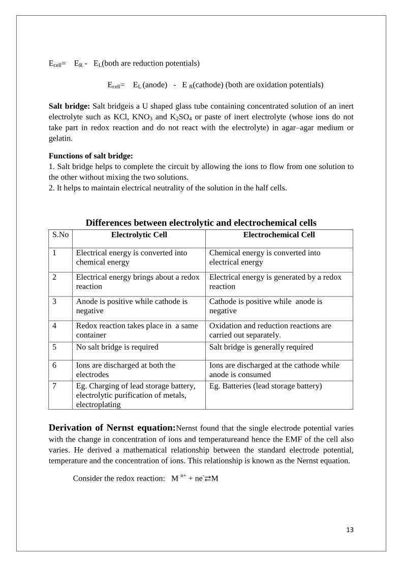
Differences between electrolytic and electrochemical cells
S.No Electrolytic Cell Electrochemical Cell
1 Electrical energy is converted into
chemical energy
Chemical energy is converted into
electrical energy
2 Electrical energy brings about a redox
reaction
Electrical energy is generated by a redox
reaction
3 Anode is positive while cathode is
negative
Cathode is positive while anode is
negative
4 Redox reaction takes place in a same
container
Oxidation and reduction reactions are
carried out separately.
5 No salt bridge is required Salt bridge is generally required
6 Ions are discharged at both the
electrodes
Ions are discharged at the cathode while
anode is consumed
7 Eg. Charging of lead storage battery,
electrolytic purification of metals,
electroplating
Eg. Batteries (lead storage battery)
Derivation of Nernst equation:Nernst found that the single electrode potential varies
with the change in concentration of ions and temperatureand hence the EMF of the cell also
varies. He derived a mathematical relationship between the standard electrode potential,
temperature and the concentration of ions. This relationship is known as the Nernst equation.
Consider the redox reaction: M n+
+ ne-M

14
In the above reversible reaction the free energy change (G) and its equilibrium
constant (K) are related by the following equation which is popularly known as Van‟t Hoff
reaction isotherm.
∆ G = RT ln K + RTln product
reactant
∆ G = ∆G0 + RTln
product
reactant
When ∆ G0
is the standard free energy change
The free energy change is equivalent to the electrical energy –nFE
Where n = valency
F = Faraday (96500 coulombs)
E = Electrode potential
R = 8.314 Joules K-1
mole-1
(Gas constant)
T = Temperature (K)
-nFE = - nFE0 + RTln([M])/([M
n+]) (Concentration of M is unity)
-nFE = - nFE0 – RTln [M
n+]
= - nFE0 – RT2.303 log10 [M
n+]
Dividing the equation by – nF
E = E0+
+2.303𝑅𝑇
𝑛𝐹 log10 [M
n+]
2.303𝑅𝑇
𝑛𝐹 =
0.0591
𝑛
Reference electrodes:
The electrode of standard potential, with which we can compare the potentials of an
other electrode is called a reference electrode. The best reference electrode used is standard
hydrogen electrodes. Its electrode potential at all temperatures is taken as zero.
The different types of electrodes are:
1) Metal-Metal ion electrode
2) Metal-Metal insoluble electrode
E = E0 +
0.0591
𝑛 log10 [M
n+]

15
3) Gas -ion electrode
4) Redox electrode
5) Glass electrode
1) Metal-Metal ion electrode: An electrode of this type consists of a metal rod dipped in to a
solution of its own salt.
E.g.: Zn rod dipped in a solution of ZnSO4 (Zn/ZnSO4)
2) Metal -Metal insoluble electrode: These electrodes consist of a metal in contact with a
sparingly soluble salt of the same metal dipped in a solution containing anion of the salt.
E.g.: Calomel electrode (Hg/Hg2Cl2/Cl-)
3) Gas-ion electrode: It consists of an inert metal dipped in a solution containing ions to
which the gas is reversible
E.g.: Hydrogen electrode
4) Redox electrode: It consists of an inert metal dipped in a solution containing ions in two
oxidation states of the substance.
E.g: Quinhydrone electrode (Pt/Q/H2Q)
5) Glass electrode: E.g: Ag/AgCl(s), HCl (0.1M)/ Glass+
Standard Hydrogen Electrode (or) Gas electrode:
It is a redox electrode which is widely used as reference electrode. It can be used as either
anode or cathode depending upon the nature of the half-cell for which it is used. The standard
hydrogen electrode consists of a platinum electrode immersed in a solution with a hydrogen
ion concentration of 1.0 M. The platinum electrode is made up of a small square of platinum
foil which is platinized and known as platinum black.
A stream of pure hydrogen is bubbled around the platinum foil at a constant pressure of one
atmosphere.The SHE may be represented as
H2 (1atm); Pt/H+ (C = 1)
The electrode potential of SHE = Zero. Depending on half-cell to which it attached hydrogen
electrode can act as a cathode or anode.
At oxidation reactions act as anode: 1
2H2 (g) (1atm) →H
+ (1M) + e
-
At reduction reaction act as cathode: H+ (1M) +e
-→1
2H2 (g) (1atm)
Nernst equation:

16
The concentration effect i.e. when H+ concentration is not 1M the EMF of the electrode
alters. To calculate the potential of the standard electrode, Nernst equation is used as given
below.
E = Eo -2.303RT/nF log10 [H
+]
Substituting all the values we get the potential of the electrode at 25oC as
E = Eo -
10
2.303 8.313 298[ ]
1 96500log H
E=Eo – 0.0591 log10 [H
+]
E=E0 – 0.0591 P
H
( ) ( ) 10
0.0591[ ]o
red oxE E E Log Hn
Saturated Calomel Electrode:

17
Calomel electrode is a metal-metal salt ion electrode.It consists of mercury, mercuous
chloride and a solution of KCl. Mercury is placed at the bottom of a glass tube having a side
tube on each side.Mercury is covered by a paste of mercurous chloride (calomel) with
mercury & KCl.
A solution of KCl is introduced above the paste through the side tube. A platinum wire
sealed in a glass tube is dipped into mercury and used to provide the external electrical
contact. The concentration of KCl used is either decinormal, normal (or) saturated.The
electrode is known as decinormal, normal, saturated calomel electrode.
The electrode whose potential is to be determined is connected to this electrode
through salt bridge. The potential of electrode depends upon the concentration of KCl
solution.
The net reversible electrode reaction is;
Hg2Cl2(s) +2e- 2Hg (l) + 2Cl-
NERNST EQUATION:
E = E0Hg2Cl2−
2303RT
2Flog[Cl-]2
= E0−2.303RT
Flog [Cl-]
= E0−0.0591log[Cl-]
The electrode potential depends up on the conc. of KCl solution(i.e.chloride ions)
At 250C For Saturated KCl solution electrode potential is 0.2415 volts.

18
For 1N KCl solution standard reduction potential is 0.281 volts.
For 0.1N KCl solution the reduction potential is 0.3338 volts.
The electrode can be coupled with hydrogen electrode containing solution of unknown
concentration.
-Pt, H2 (1atm)// H
+ =? //Hg2Cl2 (s)/Hg
+
The e.m.f. of the cell,
Ecell = Eright−Eleft= 0.2422V + 0.0592VPH
PH= Ecell −0.02422 V
0.0592V
USES:
1. It is used as a secondary reference electrode in the measurement of single electrode
potential.
2. It is the most commonly used reference electrode in all potentiometric determinations.
Quinhydrone Electrode:
C6H4 O2+2H++2e
-C6 H4 (OH) 2
Quinone (Q) Hydroquinone (QH2)
Quinone and hydroquinone form a reversible redox system in the presence of hydrogen ions.
The potential E developed when an inert electrode, e.g. platinum is immersed in this system
is given by the Nernst reduction equation.
EQ=EQ0-
2.303RT
nFlog
[QH 2]
[Q][ H+]2
19
WhereEoQ is the standard potential of the electrode.
Since [Q] = [QH2], Concentration of quinine and hydroquinone are equal. Thus,
EQ= E0Q-2.303𝑅𝑇
2𝐹log
1
[H+]2
EQ= EQ0 -
2.303RT
Flog
1
[H+]
EQ = E0
Q +2.303𝑅𝑇
𝐹log [H
+]
EQ = EQ0+ 0.05915 P
H
= 0.6994v-0.0592vPH
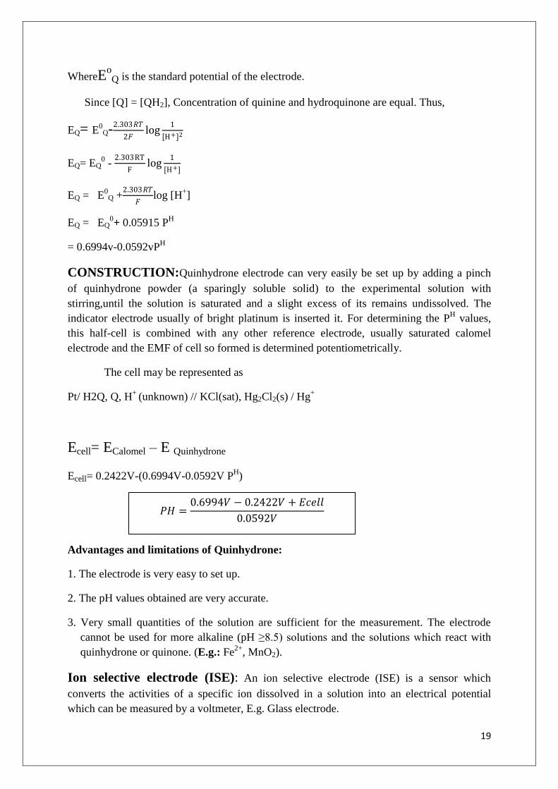
CONSTRUCTION:Quinhydrone electrode can very easily be set up by adding a pinch
of quinhydrone powder (a sparingly soluble solid) to the experimental solution with
stirring,until the solution is saturated and a slight excess of its remains undissolved. The
indicator electrode usually of bright platinum is inserted it. For determining the PH values,
this half-cell is combined with any other reference electrode, usually saturated calomel
electrode and the EMF of cell so formed is determined potentiometrically.
The cell may be represented as
Pt/ H2Q, Q, H+
(unknown) // KCl(sat), Hg2Cl2(s) / Hg+
Ecell= ECalomel – E Quinhydrone
Ecell= 0.2422V-(0.6994V-0.0592V PH)
Advantages and limitations of Quinhydrone:
1. The electrode is very easy to set up.
2. The pH values obtained are very accurate.
3. Very small quantities of the solution are sufficient for the measurement. The electrode
cannot be used for more alkaline (pH ≥8.5) solutions and the solutions which react with
quinhydrone or quinone. (E.g.: Fe2+
, MnO2).
Ion selective electrode (ISE): An ion selective electrode (ISE) is a sensor which
converts the activities of a specific ion dissolved in a solution into an electrical potential
which can be measured by a voltmeter, E.g. Glass electrode.
𝑃𝐻 =0.6994𝑉 − 0.2422𝑉 + 𝐸𝑐𝑒𝑙𝑙
0.0592𝑉

20
Glass Electrode: A glass electrode is a type of ion- selective electrode and consists of a thin-
walled glass bulb attached to a glass tube. A very low melting point and high electrical
conductivity glass are used for the construction of this bulb. The glass tube contains a dilute
solution of constant pH of HCl (0.1N) solution. A silver–silver chloride electrode or platinum
wire is immersed as reference electrode in the HCl solution. The working of glass electrode is
based upon the observation that when a glass surface is in contact with a solution, there exists
a potential difference between the glass surface and the solution, the magnitude of which
depends upon the H+
ion concentration of the solution and the nature of glass. The glass
electrode may be represented as
Ag, AgCl (s) /0.1 N HCl / glass /H+ = unknown
The electrode potential of the glass electrode depends up on the concentration of H+
ions contained in the experimental solution and are given by.
EG = Eo
G+ 2.303𝑅𝑇
𝐹log𝐻+
= Eo
G – 0.059logH+
= Eo
G + 0.0591pH

21
Eo
G is the standard electrode potential, i.e. the potential of the glass electrode when the
solution contains unit concentration of H+ions.
The value of Eo
G depends on the nature of the glass used in the construction of the bulb.
The pH of the solution can be determined if the potential of the glass electrode is
known. To determine the value of glass electrode potential (EG), the glass electrode is
combined with a reference electrode such as calomel electrode. The EMF of this cell will be
given by
E cell= E (calomel)- E (glass)
= Ec- Eg0- 0.0591P
H
PH =
Ec−Eg−𝐸𝑐𝑒𝑙𝑙
0.0591
Advantages of glass electrode:
1. Glass electrode is easy to operate and equilibrium is rapidly reached.
2. The PH value obtained is very accurate.
Limitations of glass electrode:
1. Glass electrode can be used in solutions with pH range 0-10, because electrodes are
composed of special glass that can be used up to pH 12.
2. The resistance is extremely high in the order of 10 to 100 million ohms, which cannot be
measured by ordinary potentiometers and special electronic potentiometers have to be used.
APPLICATIONS OF NERNST EQUATION:
1. It can be used to study the effect of electrolyte concentration on electrode potential.
E = Eo – RT/nFln[1/M
n+]
2. It can also be used for the calculation of the potential of a cell under non-standard
conditions.
For example,
Cu(s)/Cu2+
(aq)(0.50M)//H+(0.01)/H2(0.95atm)
Ecell= Eocell−
0.0591
2log(Cu
2+)PH2/[H
+]2
3. Determination of unknown concentration of one of the ionic species in a cell is
possible with the help of Nernst equation, provided Ecell and concentration of other
ionic species are known.
4. The pH of a solution can be calculated from the measurement of EMF and Nernst
equation.
5. Nernst equation can also used for finding the valence of an ion or the number of
electrons involved in the electrode reaction.

22
Concentration cells: In the concentration cell, the EMF is produced due to the difference
in the concentration of the electrodes or in the concentration of electrolyte, i.e., a
concentration cell is an electrochemical cell which produces electrical energy by the transfer
of a material from a system at higher concentration to a system at lower concentration. The
difference in concentration may be due to the difference in concentration of electrodes or
electrolyte. Based on this concentration, cells are classified into groups;
(i) Electrode Concentration Cells
In these cells,the potential difference is developed between two like electrodes at different
concentrations dipped in the same solution of the electrolyte. For example,two hydrogen
electrodes at different gas pressure dipped in the same solution of hydrogen ions constitute a
cell of this type.
Pt/H2 (pressure P1) / H+ (a) / ( H2 (pressure P2) /Pt
If P1>P2 oxidation occurs at L.H.S. electrode and reduction occurs at R.H.S .electrode
H2 (P1) = 2H+
+ 2e-
2H++ 2e
- = H2 (P2)
---------------------------------------
H2 (P1) = H2 (P2)
---------------------------------------
Ecell = 0.0591
2log
P1
P2

23
ELECTROLYTE CONCENTRATION CELLS:
A concentration cell consists of two half cells having identical electrodes and electrolytes at
different concentrations. The electrical energy in a concentration cell arises due to the transfer
of a substance from the solution of high concentration to solution of low concentration. The
concentration cell can represented as
Zn/ ZnSO4 (C1) // ZnSO4 (C2)/ Zn
The electrolytes are connected by a salt bridge of ammonium nitrate.
Theory: When a metal electrode is dipped in a solution of its own ions with concentration
(C) then a potential E is developed at the electrode in accordance with the Nernst equation.
0 2.303log
RTE E C
nF
0 0.0591logE E C
n
Concentration cell represented as M / Mn+
(C1) // Mn+
(C2) / M+
Where C1 and C2 are the concentration of the active metal ions (Mn+
) in contact with the same
two metal electrodes and C2> C1.
Emf of the cell (E) = E0 right - E
0 left.
0 0
2 1
2
1
2
1
0.0591 0.0591log log
0.0591log
2.303log
E C E Cn n
CE
n C
or
CRTE
nF C
Applications of concentration cell:
1. To determine the solubility of a sparingly soluble salt.

24
2. To calculate the valency of cations.
3. To determine the transition point.
4. To calculate the extent of corrosion in metals.
ELECTROCHEMICALSERIES: Metals arranged in the increasing order of standard
electrode reduction potential or decreasing order of standard oxidation potential as compared
to that of standard hydrogen electrode is called electrochemical series. These standard
electrode potentials are measured at 250C
In this series, iron lies above hydrogen and copper lies below it. Hence, if an iron rod is
dipped in CuSO4 solution a layer of copper metal will get deposited on the surface of the iron
rod.
Fe → Fe++
+2e-
Cu++
+2e-→Cu
Fe + Cu++
→ Fe++
+Cu.
The reverse of this reaction is not possible, i.e. a copper rod dipped in FeSO4solution will not
show redox reaction.
Applications of Electrochemical Series:
1. Comparison of oxidizing and reducing power: It gives information about the relative
ease with which oxidation and reduction of metal occurs. Based on the electrochemical series
the element with higher reduction potential have a greater tendency to get reduced and act as
25
good oxidizing agents. Whereas the elements with lower reduction potential have a tendency
to get oxidized and act as good reducing agents.
Ex: F2 can be reduced easily than Li+ ions. So it is a good oxidizing agent
2. Relative activities of metal: Provides information about the replacement tendencies of
metals. The greater the O.P of a metal, more easily it can lose electrons and greater is its
reactivity, i.e. the metal with higher O.P can displace the metal with lower O.P. in their salt
solution.
Ex: Mg > Zn > Fe > Cu > Ag. Zn has lower reduction potential than Cu. Hence Zn can
displace copper from CuSO4 solution
3. Any metal above hydrogen will displace hydrogen from dil.acid solution. For example,
Na reacts with water to liberate hydrogen because
E0 (Na
+/Na) = -2.714 V is less than E
0(H
+ / H2= 0).
2Na + H2SO4 → Na2SO4 +H2
2K + H2SO4 → K2SO4 + H2
Ca + H2SO4 → CaSO4 +H2
4. Provides information about the relative corrosion tendencies of metals.
5. Predicts spontaneity of redox reaction. If EMF of a cell is –ve, the reaction is non
spontaneous and if EMF is +ve then the reaction is spontaneous.
6. This series is also helpful in direct calculation of the EMF of cell formed between
electrodes.
E0= -0.76V (reduction potential)
E0= 0.34V (reduction potential)
E0 = ER-EL
= 0.34-(0.76) = 1.10V
Potentiometric titrations:
The potential of electrode depends upon the concentration of the ions to which it is reversible
in accordance with Nernst equation. Thus in a titration, the potential of an electrode is
measured by the change in ionic concentration.
The potentiometric titrations are those titrations which involve the measurement of electrode
potentials with the addition of the titrant. The end point is detected by measuring the changes
in the potential of a suitable electrode during the course of reaction. No indicator is used in
this titrations. The end point of the reaction is indicated by a sharp change in the potential of
the system.
(i) ACID BASE TITRATIONS:

26
The acid solution whose strength has to be determined is taken in a beaker and the hydrogen
electrode and calomel electrode were dipped in the solution. The electrodes were connected
to the potentiometer and the E.M.F is measured. A known volume of standard alkali solution
is added from a burette and stirred and the EMF of the cell is recorded. Like this 10-15
readings are recorded by repeating the procedure of the addition of standard alkali.
On adding alkali solution (NaOH) from the burette, the H+ concentration goes on
decreases, i.e. pH of the solution goes on increases and hence the EMF of the cell goes on
increases gradually, but at the end point the rate of change of potential will be suddenlyquite
large. After the end point, further addition of NaOH produces very little change in the H+ ion
concentration and hence there is very little change in the EMF of the cell.
The complete cell may be represented as
Pt, H2 (1atm) / H+
(unknown) //KCl (sat. soln) / Hg2Cl2.Hg
The emf of the indicator electrode (hydrogen electrode) is given as
EH2/H+ = EoH2/H+ + 0.0591 log10 [H
+]
A graph is plotted by taking volume of alkali added against EMF observed. A sigmoid curve
is obtained and the steepest portion of the curve indicates the equivalence point of the
titration
From the graph, we draw the conclusion
that the EMF increases with the decrease in
concentration of hydrogen ions because electrode potential of indicator electrode depends on
the concentration of H+ ions.
(ii) OXIDATION- REDUCTION TITRATIONS:
The procedure adopted for oxidation titration is the same as in acid-base titration; the only
difference is that the electrode reversible to hydrogen ions is replaced by a bright platinum
electrode. The EMF of the electrode is determined by the activity of ratio of the substance
being oxidized or reduced. For E.g.; Fe2+
titrated against K2Cr2O7. The Fe2+
solution is taken
in the beaker, treated with dil.H2SO4 and Pt electrode and calomel electrodes are dipped. The
electrodes are connected to the potentiometer and EMF of the solution after the addition of
K2Cr2O7 is recorded. On addition of K2Cr2O7 from the burette, EMF of the cell increase first
slowly, but at the equivalence point there will be sudden jump in potential, since change in
ratio of Fe2+
/Fe3+
ion concentration. A graph is plotted with EMF and volume of K2Cr2O7. A

27
sigmoid curve is obtained and the steepest portion of the curve indicates the end point of the
titration.
(iii) PRECIPITATION REACTION:
In precipitation reaction also an electrode reversible to one of the ions involved is
made use of, for E.g: titration of AgNO3 with NaCl, where AgCl precipitates out, Ag-
electrode is used along with calomel electrode. The silver nitrate is placed in the micro
burette and added to sodium chloride taken in the beaker, containing electrodes. The EMF of
the cell is measured and plotted against volume of silver nitrate added. The steep rise in the
curve shows the end point of the titration.
DETERMINATION OF PH
BY EMF METHOD:
The EMF of a solution depends on the concentration of H+ ions or pH of the solution. A
hydrogen electrode containing solution of unknown PH is paired with a standard calomel
electrode.
The complete cell may be represented as
Pt, H2 (1atm) / H+
(unknown) //KCl (sat. soln) / Hg2Cl2.Hg
The EMF of the above cell is measured by potentiometer, and the PH of the unknown
solution can be calculated as follows.
The EMF of the cell will be given by the expression
E cell = E right - E left
E cell = 0.2415 - (- 0.0591 PH)
E cell = 0.2415 + 0.0591 PH
BATTERIES- PRIMARY AND SECONDARY CELLS;
Battery is an electrochemical cell or often several electrochemical cells connected in series
that can be used as a source of direct electric current at constant voltages. A device which
converts chemical energy to electrical energy is called battery cells, connected together
electrically in series. Batteries are commercial electrochemical cells.

28
ADVANTAGES OF BATTERIES:
(1) Batteries act as a portable source of electrochemical energy.
(2) The portability of electronic equipment in the form of handsets has been made possible by
batteries.
(3) A variety of electronic gadgets have been made more useful and popular with the
introduction of rechargeable storage batteries having reliability, better shelf life and
tolerance to service.
(4) For all commercial applications, batteries are constructed for their service. For example
batteries for automotives and aircrafts, stand by batteries etc.
The following requirements should be possessed by the batteries.
(1) High capacity, which is very small variation of voltage during discharge.
(2) High energy efficiency, which is calculated as
% of efficiency = energy released on discharge/energy required for charge x100
(3) High cycle life is required which is the number of charging and discharging cycles before
failure.
(4) Long shelf-life is required.
(5) Tolerance to different service conditions such as variation in temperature, vibration shock
etc.
(6) Reliability is another important criteria.
Differences between Primary, Secondary and Fuel cells:
Primary cell Secondary cells Fuel Cell
It acts as a simple galvanic cell. It act as a galvanic cell
while discharging and
electrolytic cell while
charging.
It acts as a simple galvanic
cell.
Cell reaction is notreversible. Cell reaction can
bereversed.
Cell reaction is not
reversible
Cannot be recharged. Can be recharged Do not store energy
29
Can be used as long as the
materials are active in their
composition.
E.g:
Leclanche or dry cell.
Zn/NH4Cl (20%), ZnCl2/
MnO2/C. emf =1.5V.
Applications;
radios,torches,transistors,hearing
aids
.
Can be used again and
again by recharging the cell
E.g:
1. Lead storage cell 2. Nicol
or Nickel cadmium battery
emf =1.4
Applications: electronic
calculators, electronic flash
units &cordless electronic
shavers etc.
Energy can be withdrawn
indefinitely as long as
outside supply of fuel is
maintained
E.g:
H2-O2, CH3OH-O2
Applications:
Space vehicles due to their
light weight and the bi
product H2O produced is a
valuable source of fresh
water for astronauts.
PRIMARY CELLS:
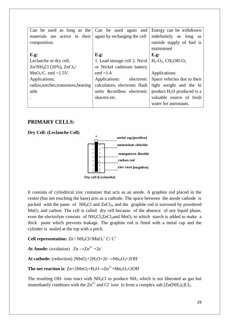
Dry Cell: (Leclanche Cell)
It consists of cylindrical zinc container that acts as an anode. A graphite rod placed in the
center (but not touching the base) acts as a cathode. The space between the anode cathode is
packed with the paste of NH4Cl and ZnCl2, and the graphite rod is surround by powdered
MnO2 and carbon. The cell is called dry cell because of the absence of any liquid phase,
even the electrolyte consists of NH4Cl,ZnCl2and MnO2 to which starch is added to make a
thick paste which prevents leakage. The graphite rod is fitted with a metal cap and the
cylinder is sealed at the top with a pitch.
Cell representation: Zn-/ NH4Cl//MnO2
+ C/ C
+
At Anode: (oxidation) Zn →Zn2+
+2e-
At cathode: (reduction) 2MnO2+2H2O+2e-→Mn2O3+2OH
-
The net reaction is: Zn+2MnO2+H2O→Zn2+
+Mn2O3+2OH-
The resulting OH- ions react with NH4Cl to produce NH3 which is not liberated as gas but
immediately combines with the Zn2+
and Cl- ions to from a complex salt [Zn(NH3)2]Cl2.

30
2NH4Cl+ 2OH- →2NH3+ 2Cl
-+2H2O
Zn2+
+ 2NH3+2Cl-→[Zn(NH3)2]Cl2
Net reaction:
Zn(s) + 2NH4Cl + 2MnO2(s) → Mn2O3(s) + [Zn(NH3)2]Cl2(s) + 2H2O.
Applications
1. These cells have voltage ranging from 1.25V to 1.50V.
2. Primary cells are used in torches, radios, transistors, hearing aids, pacemakers, watches.
3. Price is low.
Disadvantages:
1. These cells do not have a long life, because the acidic NH4Cl corrodes the container even
when the cell is not in use.
2. When current is rapidly drawn from the cell, voltage drop takes place due to the building
up of production on the electrodes.
Lithium cells:Lithium cells are primary cells in which lithium acts as anode and the
cathode may differ. Lithium metal is used as anode because of its light weight, high standard
oxidation potential (≥3V) and good conductivity.As the reactivity of lithium in aqueous
solution is more, lithium cells use non-aqueous solvents as electrolyte.
Lithium cells are classified into two categories:
(a).Lithium cells with solid cathode: The electrolyte in this system is a solid electrolyte.
The most widely used cell is lithium – manganese dioxide cell (3V).MnO2 should be heated
to over 3000C to remove water before keeping it in the cathode, thereby increasing the
efficiency of the cell.
Anode: Lithium Metal,
Cathode: MnO2 as an active material.
Electrolyte: LiBF4salt in a solution of propylene carbonate and dimethoxy ethane.
Reactions:
At anode: Li⟶ Li + + e
-

31
At cathode: e- + MnO2⟶ MnO2
-
Net reaction: Li+ MnO2⟶ LiMnO2
Applications:
1. The coin type cells are used in watches and calculators.
2. Cylindrical cells are used in fully automatic cameras.
(b) Lithium cells with liquid cathode: Lithium–sulphur dioxide cell is an example of liquid
cathode.The co-solvents used areacrylonitrile or propylene carbonate (or) mixture of the
two with SO2 in 50% by volume.
Cell reaction: 2Li + 2SO2⟶ Li2S2O4.
Lithium thionyl chloride cell is another example of liquid cathode. It consists of high
surface area carbon cathode, a non – woven glass separator. Thionyl chloride acts as an
electrolyte and as a cathode.
Cell reaction:
At anode:Li ⟶ Li+ + e
-
At cathode: 4Li+ 4e-+ 2SOCl2⟶ 4LiCl+SO2+S
Net reaction: 4Li + 2SOCl2⟶ 4LiCl+SO2+S
In this cell no co-solvent is required as SOCl2 is a liquid with moderate vapor pressure. The
discharging voltage is 3.3 -3.5V.
USES:
1. They are used for military and space applications.
2. In medicinal devices such as neuro-stimulators, drugdelivery system, lithium batteries
are widely used.
3. They are also used in electric circuit boards for supplying fixed voltage for memory
protection and standby functions.
Advantages:

32
1. The energy output of a lithium cell is 2-4 times better than that of conventional zinc
anode batteries.
2. Lithium batteries can work over temperature range of 40-700C.
3. They have higher voltages of about 4V when compared to other primary cells with 1.5 V
only.
Secondary cell: E.g.:Lead – Acid cell:
If a number of cells are connected in series, the arrangement is called a battery. The lead
storage battery is one of the most common batteries that are used in the automobiles. A 12 V
lead storage battery is generally used, which consists of six cells, each providing 2V. Each
cell consists of a lead anode and a grid of lead packed with lead oxide as the cathode. These
electrodes are arranged alternately, separated by a thin wooden piece and suspended in dil.
H2SO4 (38%), which acts as an electrolyte. Hence, it is called lead acid battery.
Anode: Pb
Cathode: PbO2
Electrolyte: H2SO4 (20-22%)
EMF = 2 V
Lead storage cells: To increase the current output of each cell, the cathode and the anode
plates are joined together, keeping them in alternate positions. The cells are connected
parallel to each other. The cell is represented as
Pb/PbSO4(s), H2SO4/PbSO4(s),Pb
In the process of discharging, i.e., when the battery produces current, the reactions at the
electrodes are as follows:
Discharging reactions:

33
At anode: Pb → Pb2+
+ 2e-
Pb2+
+ SO42-
→ PbSO4↓
At cathode:PbO2(s) +4H+ +2e
-→Pb
2++2H2O
Pb2+
+SO42-
→PbSO4
Therefore, the overall reaction is:
During discharging the battery, H2SO4 is consumed, and as a result, the density of H2SO4
falls. When it falls below 1.20 g/cm3, the battery needs recharging. In discharging, the cell
acts as a voltaic cell where oxidation of lead occurs.
Recharging: During recharging, the cell is operated like an electrolytic cell, i.e. electrical
energy is supplied to it from an external source. The electrode reactions are the reverse of
those that occur during discharge.
PbSO4 + 2e- → Pb + SO4
2-(Reaction at cathode)
PbSO4 + 2H2O→ PbO2 + 2H2SO4 + 2e- (Reaction at anode)
-------------------------------------------------------------------------
2PbSO4 + 2H2O + Energy → Pb + PbO2 + 2H2SO4
During this process, lead is deposited at the cathode, PbO2 is formed at the anode and
H2SO4 is regenerated in the cell.
Advantages: Lead-acid batteries are used for supplying current to railways, mines,
laboratories, hospitals, automobiles, power stations, telephone exchange, gas engine ignition,
UPS. Other advantages are its recharge ability, portability, and relatively constant potential
and low cost.
Disadvantages: Use of conc. H2SO4 is dangerous. Use of lead battery is fragile.
Nickel – Cadmium Cell:
It is a rechargeable secondary cell. It consists of cadmium as the negative electrode
(anode) and NiO2 as the positive electrode (cathode). Potassium hydroxide (KOH) is used as
an electrolyte. The cell reaction during charging and discharging are as follows.
Pb(s) +PbO2+4H2SO4(aq) → 2PbSO4(s) + 2H2O + Energy

34
Anode: Cd
Cathode:NiO(OH)
Electrolyte: KOH
EMF = 1.4 V
At anode: Cd + 2OH Cd(OH)2(s) + 2e-
At cathode: NiO2 + 2H2O + 2e-
2 Ni(OH)2 + 2OH-
Overall reaction:
Cd + 2NiO(OH) + 2H2O Cd(OH)2 + 2Ni(OH)2
Uses:
1. The nickel-cadmium cell has small size and high rate of charge/discharge capacity, which
makes it very useful.
2. It also has very low internal resistance and wide temperature range (up to 700C).
3. It produces a potential of about 1.4 V and has a longer life than lead storage cell.
4. These cells are used in electronic calculators, electronic flash units, electrical shavers,
transistors, etc.
5. Ni–Cd cells are widely used in medical instrumentation and in emergency lighting, toys,
etc.
6. It is also used in aircraft and space satellite power system.
Advantages:
1. Ni-Cd batteries last longer, in terms of number of charge/discharge cycles, than other
rechargeable batteries.
2. Ni-Cd batteries have much higher energy efficiency.

35
Fuel Cells:
Definition: A fuel cell is an electrochemical which converts chemical energy contained in
readily available fuel oxidant system into electrical energy.
Principle: The basic principle of fuel cell is as same as that of an electrochemical cell. The
fuel cell operates like a galvanic cell. The only difference is that the fuel and the oxidant are
stored outside the cell. Fuel and oxidant are supplied continuously and separately to the
electrodes at which they undergo redox reaction. Fuel cells are capable of supplying current
as long as reactants are replenished.
Fuel + Oxidant → Oxidation products+Electric Energy
Examples: 1. H2-O2 fuel cell
2. CH3OH-O2 fuel cell
Hydrogen oxygen fuel cell: This cell is a common type of fuel cell. Similar to a galvanic
cell, fuel cell also have two half cells. Both half cells have porous graphite electrode with a
catalyst (platinum, silver or a metal oxide). The electrodes are placed in the aqueous solution
of NaOH or KOH which acts as an electrolyte. Hydrogen and oxygen are supplied at anode
and cathode respectively at about 50 atmospheric pressure, the gases diffuse at respective
electrodes. The two half-cell reactions are as follows;
At anode: 2H2 (g) + 4OH- (aq) 4H2O (l) + 4e
-
At cathode: O2 (g) + 2H2O (l) + 4e- 4OH
- (aq)
The net reaction: 2H2 (g) + O2 (g) 2H2O (l)
The EMF of this cell is measured to be 1.23V. A number of such fuel cell are stacked
together in series to make a battery.
Advantage:
1. The energy conversion is very high (75-82%).
2. Fuel cell minimizes expensive transmission lines and transmission losses.
3. It has high reliability in electricity generation.

36
4. The byproducts are environmentally acceptable.
5. Maintenance cost is low for these fuels.
6. They save fossil fuels.
7. Noise and thermal pollution are very low.
8. They have low maintenance cost.
9. They have quick start system.
Disadvantage:
1. The major disadvantage of the fuel cell is the high cost and the problems of durability and
storage of large amount of hydrogen.
2. The accurate life time is also not known.
APPLICTIONS:
1. The most important application of a fuel cell is its use in space flight.
2. It is hoped that fuel cell technology will bring a revolution in the area of energy
production.
3. Fuel cell batteries for automotive will be a great boom for the future.
Limitation:
1.The life time of fuel cells is not accurately known
2.Their initial cost is high
3.The distribution of hydrogen is not proper
Methyl Alcohol- Oxygen (Alkaline Fuel Cell):
In this fuel cell, CH3OH is used as a fuel and O2 as oxidant to generate electrical energy. The
methyl alcohol–oxygen fuel cell has two electrodes. The anode consists of porous nickel
electrode impregnated with Pt/Pd catalyst. Porous nickel electrode coated with silver catalyst
constitutes a cathode of the cell. The electrolyte, KOH, is taken in between the two
electrodes. CH3OH and O2 are sent continuously into their respective electrodes as shown in
Fig. and the electrical energy is produced with the continuous replenishment of the fuel,
CH3OH at the anode.
At anode: CH3OH + 6OH-→ CO2 +5H2O +6e
-
At cathode: 3/2 O2 +3H2O + 6e-→ 6OH
-

37
Overall reaction: CH3OH +3/2 O2 →CO2 +2H2O
Advantage of methyl alcohol-oxygen fuel cell:
1. Methanol fuel cells are reasonably stable at all environmental conditions.
2. Easy to transport
3. Do not require complex steam reforming operation.
4. These fuel cells are targeted to portable applications.
5. Because of high hydrogen concentration in methanol.it is an excellent fuel.
6. Methanol poses less risk to aquatic plants, animals and human beings than gasoline
7. Because methanol possess lower inflammability limit than gasoline it poses less fire
riskthan gasoline.
8. There is zero emission by the cells hence the fuel cells are eco friendly.
Application of alcohol-oxygen fuel cell:
1. The major application of methyl alcohol oxygen fuel cells is a fuel for fuel cell motor
vehicles like NECAR-5 in Japan, USA etc.
Numerical Problems:
1. A solution of salt (1.0 N) surrounding platinum electrodes 2.1cm apart and 4.2 cm2 in area
was found to offer a resistance of 50 Ω. Calculate the equivalent conductivity of the
Solution.l = 2.1 cm, C= 1.0N
a= 4.2cm2
R= 50
Specific conductance (K) = 1
𝑅.𝑙
𝑎
=1
50×
2.1
4.2= 0.01Ω
-1cm-1
Equivalent conductance ( λ eq) = 𝐾 ×1000
𝐶
= 0.01 ×1000
1
=10Ω-1
cm2equiv
-1.
2.Specific conductance of a decinormal solution of KCl is 0.0112 ohm-1
cm-1
. The resistance
of a cell containing the solution was found to be 56 Ohms. What is the cell constant.
Solution: K= 0.0112Ω-1
cm-1
R=56Ω
Cell constant =Specific conductance ×Resistance
= K×R=0.0112×56 = 0.6272cm-1
.
3. The specific conductivity of a N/50 solution of a NaCl at 300C is 0.00368 ohm
-1cm
-1. If the
resistance offered by the solution when placed in a cell is 1,500 ohms, Calculate cell constant
and equivalent conductance of solution.

38
Solution: K =0.00368Ohm -1
cm-1
C=N/50=0.02
R = 1,500 ohms.
Equivalentconductance (λ eq) = K ×1000
C
K = 𝑙
𝑎.
1
𝑅
Cell constant ( 𝑙
𝑎) = 𝐾.𝑅
= 5.52 cm-1
Equivalent conductance (λ eq) = K ×1000
C
= 0.00368 ×1000
0.02
=184 ohm-cm
-1
4. Calculate the Emf for the cell,
Zn/Zn+ // Ag
+ /Ag given E
0Zn+/Zn
+2 / Zn = 0.762v and E
0Ag+/Ag = 0.8 v
Solution:Given cell is Zn/Zn+2
//Ag+/Ag.
E0
Zn+2/Zn = 0.762 v
E0
Ag+/Ag =0.8 v
E0
cell = E0
right – E0
left
= 0.8 – (-0.762)
= 1.562v
5.Calculate the E0Cu
+2/Cu, given E
-Cu
+2/Cu= 0.296 v and [Cu
+2] = 0.015M.
Solution: Cell reaction is Cu Cu+2
+ 2e-
E = E0
+ 𝟎.𝟎𝟓𝟗𝟏
𝒏 log [cu
+2]
0.296 = E0 +
𝟎.𝟎𝟓𝟗𝟏
𝟐 log [cu
+2]
E0 =0.296-
𝟎.𝟎𝟓𝟗𝟏
𝟐 log (0.015)
= 0.296 - 0.2955 (- 1.8239)
= 0.296 + 0.0538
= 0.3498V
6.Write the half cell and net cell reactions for the following cell,
Zn / ZnSO4 (aq) // CuSO4 (aq) / Cu.Calculate the standard emf of the cell given,
E0Zn
+2/Zn= 0.76 v and E
0Cu
+2/Cu= + 0.34V.

39
Solution: Half cell reactions
At anode: Zn Zn+2
+ 2e-
At cathode: Cu+2
+ 2e- →Cu.
Net cell reaction = Zn + Cu+2
Zn+2
+ Cu.
E0
cell = E0
Cathode – E0
Anode.
= E0
cu+2
/cu – E0
Zn+2
/ Zn
= 0.34 – (-0.76)
= 1.1 V
Unit1:Corrosion
Introduction:
The surface of almost all the metals begin to decay more or less rapidly when exposed to
atmospheric gases, water or other reactive liquid medium.
The process of decay of metal by environmental attack is known as corrosion.
Metals undergo corrosion and convert to their oxides, hydroxides, carbonates, sulphides,
etc.
Eg. Iron undergoes corrosion to form reddish brown colour rust [Fe2O3. 3H2O].
Copper undergoes corrosion to form a green film of basic carbonate [CuCO3 + Cu(OH)2]
Causes of corrosion:
1. The metals exist in nature in the form of their minerals or ores in the stable combined
forms as oxides, chlorides, silicates, carbonates and sulphides.
2. During the extraction of metals, these ores are reduced to metallic state by supplying
considerable amount of energy.
3. Hence the isolated pure metals are in excited states than their corresponding ores.

40
So metals have natural tendency to go back to their combined state (minerals/ores).When
metal is exposed to atmospheric gases, moisture, liquids etc, the metal surface reacts and
forms more thermodynamically stable compounds.
Effects of corrosion:
1. Wastage of metal in the form of its compounds.
2. The valuable metallic properties like conductivity, malleability, ductility etc. are lost
due to corrosion.
3. Life span and efficiency of metallic parts of machinery and fabrications is reduced
Theories of corrosion:
Dry corrosion or Chemical corrosion:
This type of corrosion occurs mainly through the direct chemical action of atmospheric gases
like O2, halogens, H2S, SO2, N2 or anhydrous inorganic liquid with the metal surface.
There are three types of chemical Corrosion:
1. Oxidation corrosion
2. Corrosion due to other gases
3. Liquid metal corrosion
(1.) Oxidation Corrosion: This is carried out by the direct action of oxygen at low or high
temperatures on metals in absence of moisture. Alkali metals and Alkaline earth metals are

41
rapidly oxidized at lower temperatures. At high temperature all metals are oxidized (except
Ag, Au, Pt).
M M2+
+ 2e- (Oxidation)
O2 + 2e-2O
2- (Reduction)
M + O2M2+
+ 2O2-
(Metal oxide)
Mechanism:Initially the surface of metal undergoes oxidation and the resulting metal oxide
scale forms a barrier which restricts further oxidation. The extent of corrosion depends upon
the nature of metal oxide. Further oxidation can continue if the metal diffuses out of the scale
or the oxygen must diffuse in through the scale to the under laying metal. Of the two types of
diffusions, the diffusion of the metal is rapid because the size of the metal ion is smaller than
oxygen ion, hence higher mobility to metal ion.
Stable metal oxide layer
(a) If the metal oxide layer is stable, it behaves as a protective layer which prevents further
corrosion.
E.g: The oxide films of Al, Sn, Pb, Cu, Cr, W etc. are stable and therefore further corrosion is
prohibited.
Unstable metal oxide layer
(b) If the metal oxide layer is unstable, the oxide layer formed decomposes back into metal
and oxygen then oxidation corrosion is not possible.

42
E.g: Ag, Au and Pt do not undergo oxidation corrosion.
Volatile Metal oxidelayer
(c) If the metal oxide layer is volatile, then the oxide layer volatilizes after formation and
leaves the underlying metal surface exposed for further attack.This causes continuous
corrosion which is excessive in molybdenum oxide (MoO3).
Porous Metal oxide layer
(d) If the metal oxide layer is porous, the oxide layer formed has pores or cracks. In this case
the atmospheric oxygen penetrates through the pores or cracks and corrode the underlying
metal surface. This cause continuous corrosion till conversion of metal into its oxide is
completed.Eg: Alkali and alkaline earth metals (Li, Na, K, Mg etc.)
Pilling Bedworth rule:
To express the extent of protection given by the corrosion layer to the underlying
metal Pilling Bedworth rule was postulated.
It is expressed in terms of specific volume ratio.

43
Specific Volume ratio = Volume of metal oxide layer formed
Volume of metal
Smaller the specific volume ratio, greater is the oxidation corrosion
Eg. The specific volume ratio of W,Cr, and Ni are 3.6,2.0 and 1.6 respectively.
Consequently the rate of corrosion is least in Tungsten(W)
If the volume of the corrosion film formed is more than the underlying metal, it is
strongly adherent, non-porous does not allow the penetration of corrosive gases.
If the volume of the corrosion film formed is less than the underlying metal, it forms
pores/cracks and allow the penetration of corrosive gases leading to corrosion of the
underlying metal.
Eg.Li, Na sand K.
(2)Corrosion due to other gases: This type of corrosion is due to gases like SO2, CO2, Cl2,
H2S, F2 etc. In this corrosion, the extent of corrosive effect depends mainly on the chemical
affinity between the metal and the gas involved. The degree of attack depends on the
formation of protective or non protective films on the metal surface which is explained on the
basis of specific volume ratio.
Eg.Ag + Cl22AgCl (protective film)
Eg: In petroleum industry, H2S gas at high temperature reacts with steel forming a FeS scale.
Fe (steel) + H2S FeS (porous, nonprotective)
(3)Liquid metal corrosion: This corrosion is due to chemical action of flowing liquid metal
at high temperatures on solid metal or alloy. The corrosion reaction involves either
dissolution of a solid metal by a liquid metal or internal penetration of the liquid metal into
the solid metal.
Eg: Liquid metal mercury dissolves most metals by forming amalgams, thereby corroding
them
Eg: Coolant (sodium metal) leads to corrosion of cadmium in nuclear reactors.
Wet Corrosion or Electrochemical Corrosion
This type of corrosion occurs when a conducting liquid is in contact with the metal.
This is due to the existence of separate anodic and cathodic parts, between which
current flows through the conducting solution.
At anodic area, oxidation reaction occurs there by destroying the anodic metal either
by dissolution or formation of compounds. Hence corrosion always occurs at anodic
parts.
Mechanism:Electrochemical corrosion involves flow of electrons between anode and
cathode.

44
The anodic reaction involves dissolution of metal liberating free electrons.
MMn+
+ ne-
The cathodic reaction consumes electrons with either evolution of hydrogen or absorption of
oxygen which depends on the nature of corrosive environment.
Wet corrosion takes place in two ways.
1.Evolution of Hydrogen
2.Absorption of Oxygen
EvolutionofHydrogen: This type of corrosion occurs in acidic medium.
Eg: Considering the metal Fe, anodic reaction is dissolution of iron as ferrous ions
withliberation of electrons.
Anode: FeFe
2+ + 2e
- (Oxidation)
The electrons released flow through the metal from anode to cathode, whereas H+ ions of
acidic solution are eliminated as hydrogen gas.
Cathode:2H+ + 2e
- H2 (Reduction)
The overall reaction is: Fe + 2H+Fe
2+ + H2
This type of corrosion causes displacement of hydrogen ions from the solution by metal ions.
All metals above hydrogen in electrochemical series have a tendency to get dissolved in
acidic solution with simultaneous evolution of H2 gas. In this case anodic area is large and
cathodic area is small.
45
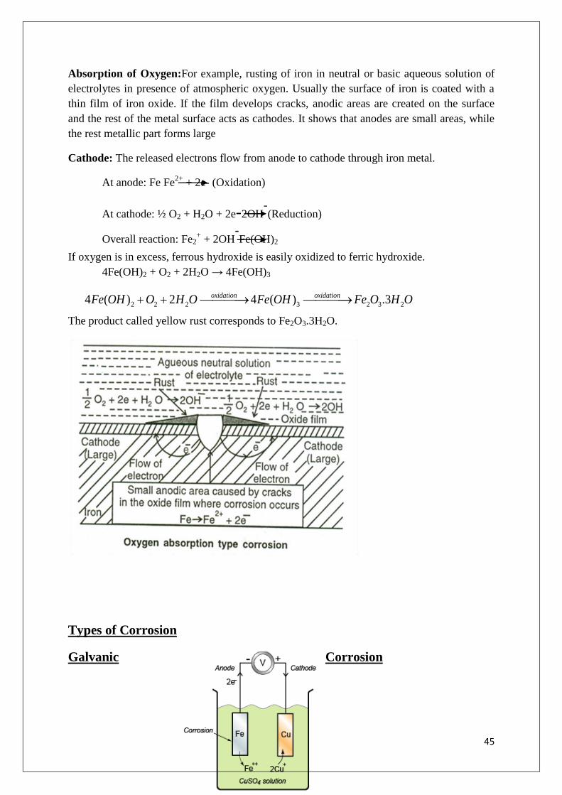
Absorption of Oxygen:For example, rusting of iron in neutral or basic aqueous solution of
electrolytes in presence of atmospheric oxygen. Usually the surface of iron is coated with a
thin film of iron oxide. If the film develops cracks, anodic areas are created on the surface
and the rest of the metal surface acts as cathodes. It shows that anodes are small areas, while
the rest metallic part forms large
Cathode: The released electrons flow from anode to cathode through iron metal.
At anode: Fe Fe2+
+ 2e- (Oxidation)
At cathode: ½ O2 + H2O + 2e-2OH-(Reduction)
Overall reaction: Fe2+ + 2OH
-Fe(OH)2
If oxygen is in excess, ferrous hydroxide is easily oxidized to ferric hydroxide.
4Fe(OH)2 + O2 + 2H2O → 4Fe(OH)3
The product called yellow rust corresponds to Fe2O3.3H2O.
Types of Corrosion
Galvanic Corrosion
2 2 2 3 2 3 24 ( ) 2 4 ( ) .3oxidation oxidationFe OH O H O Fe OH Fe O H O

46
When two dissimilar metals are electrically connected and exposed to an electrolyte,
the metal higher in electrochemical series (low reduction potential) undergoes
corrosion and the metal lower in electrochemical series (high reduction potential) is
protected. This type of corrosion is called galvanic corrosion.
Eg: When Zn an Cu are connected and exposed to corroding environment, Zinc
higher in electrochemical series forms anode,undergoes oxidation and gets corroded.
Cu lower in electrochemical series acts as cathode, undergoes reduction and protected
as the electrons released by Zn flow towards Cu.
Galvanic Series
Although electrochemical series give very useful information regarding chemical reactivity of
metals, it did not provide sufficient information in predicting the corrosion behavior under a
particular set of environmental conditions.
Hence electrode potentials of various metals and their alloys in common use are measured by
immersing them partially in sea water,and the values have been arranged in decreasing order
of activity and is called as galvanic series.
In galvanic series,oxidation potentials are arranged in the decreasing order of activity of a
series of metals.Thus galvanic series give real and useful information for studying the
corrosion tendency of metals and alloys.
Electrochemical Series Galvanic series
1. This series consists of metal and non-
metals
2. The position of metal in this series is
permanently fixed
3. It predicts relative displacement
1. This series consists of metals and
alloys
2. The position of metal is different
from that of the position of its alloy
3. It predicts the relative corrosion

47
tendencies
4. Electrode potentials are measured
bydipping the pure metal in their salt
solution of 1M concentration
tendencies
4. Electrode potentials of metals and
alloys are measured by immersing in
sea water
Galvanic Series
Concentration cell corrosion
This type of corrosion occurs due to electrochemical attack of the metal surface exposed to
electrolyte of varying concentrations or varying aeration.
This type of corrosion is due to
(i) Difference in concentration of metal ions.
(ii) Difference in the exposure to air/oxygen (Differential aeration corrosion)
(iii) Difference in temperature.
Differential aeration corrosion is the most common type of concentration cell
corrosion. When a metal is exposed to different air concentrations, it has been found
that poorly oxygenated part of the metal becomes anodic and well oxygenated part
becomes cathodic.
The potential difference is created which causes the flow of electrons from anode
(metallic part immersed in NaCl solution) to cathode (exposed to atmosphere).
Eg: Part of Zn rodimmersed deep in NaCl solution: Anode
Zn rod above NaCl solution: Cathode
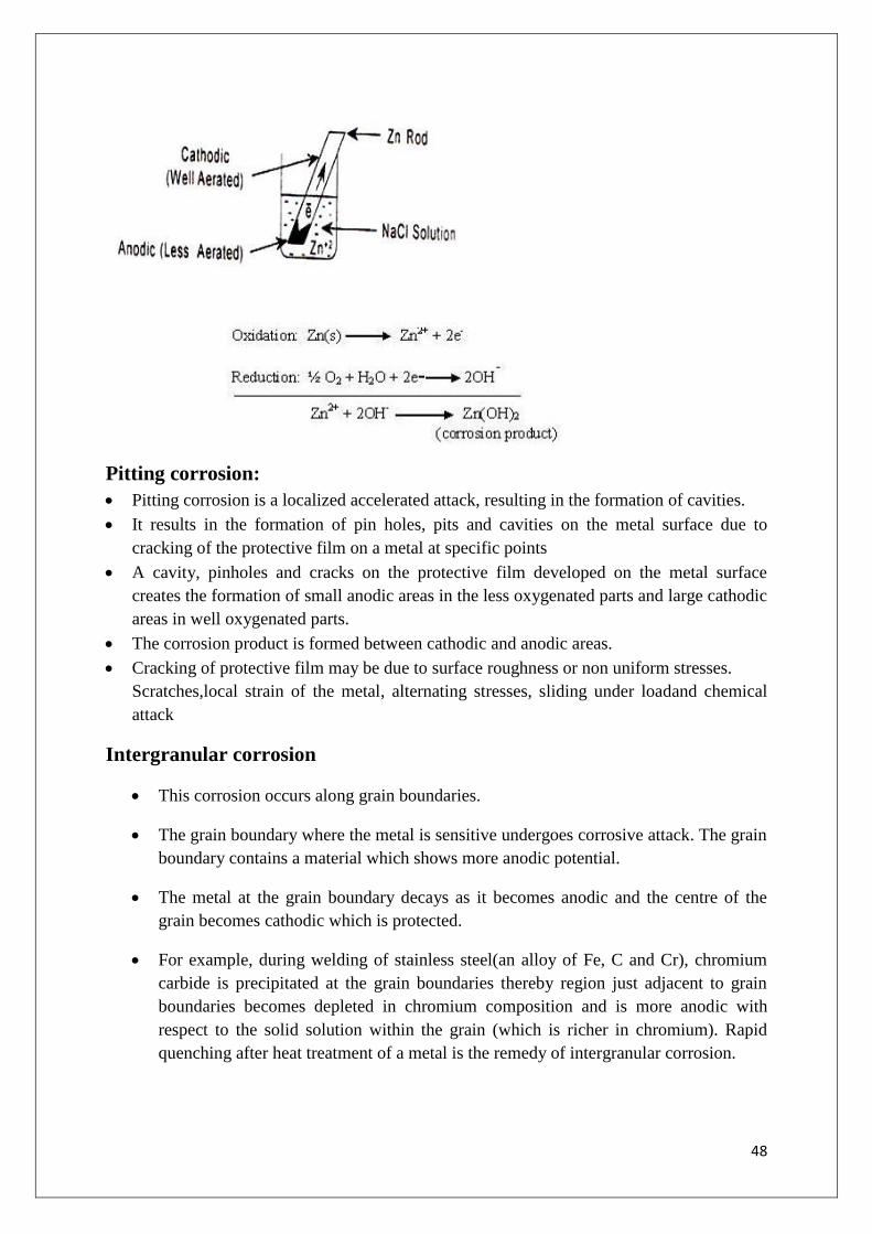
48
Pitting corrosion:
Pitting corrosion is a localized accelerated attack, resulting in the formation of cavities.
It results in the formation of pin holes, pits and cavities on the metal surface due to
cracking of the protective film on a metal at specific points
A cavity, pinholes and cracks on the protective film developed on the metal surface
creates the formation of small anodic areas in the less oxygenated parts and large cathodic
areas in well oxygenated parts.
The corrosion product is formed between cathodic and anodic areas.
Cracking of protective film may be due to surface roughness or non uniform stresses.
Scratches,local strain of the metal, alternating stresses, sliding under loadand chemical
attack
Intergranular corrosion
This corrosion occurs along grain boundaries.
The grain boundary where the metal is sensitive undergoes corrosive attack. The grain
boundary contains a material which shows more anodic potential.
The metal at the grain boundary decays as it becomes anodic and the centre of the
grain becomes cathodic which is protected.
For example, during welding of stainless steel(an alloy of Fe, C and Cr), chromium
carbide is precipitated at the grain boundaries thereby region just adjacent to grain
boundaries becomes depleted in chromium composition and is more anodic with
respect to the solid solution within the grain (which is richer in chromium). Rapid
quenching after heat treatment of a metal is the remedy of intergranular corrosion.

49
Water line corrosion
This type of corrosion is due to differential aeration corrosion.
When water is stored in a steel tank, it is generally found that the maximum amount
of corrosion takes place along a line just below the water line.
This is because the area below waterline (poorly oxygenated) acts as anode and gets
corroded.
The area above the waterline (highly oxygenated) act as cathode and is completely
unaffected by corrosion
Passivity or Passivation:
The phenomenon in which a metal or an alloy exhibits a much higher corrosion
resistance than expected from its position in the electrochemical series is called
Passivity.
It is due to formation of a highly protective, but very thin film on the surface of metal
or an alloy and makes it more noble
The film is insoluble, non porous and of self–healing nature that when broken, it will
repair itself on re-exposure to oxidizing conditions
Eg 1. Passive metals and alloys are Ti,Al,Cr and a wide variety of stain less steel
alloys containing Cr. These exhibit outstanding corrosion resistance in oxidizing
environments, but in reducing environments, they become chemically active
Eg 2.The action of more conc.Nitric acid on active metals (Fe and Al) produces a thin
protective oxide film, thereby shifting the anodic reaction and making them passive.

50
Factors effecting corrosion:
The rate and extent of corrosion depends upon various factors due to nature of metal and
nature of corroding environment.
Nature of metal:
1. Purity of the metal:
If impurities are present in a metal the corrosion rate is increased due to formation of tiny
electrochemical cells at the exposed parts and the anodic parts get corroded. A pure metal is
more corrosion resistant than impure metal. By increasing its purity the corrosion resistance
of a metal can be improved
Ex: Zn metal containing impurity undergoes corrosion of zinc, due to the formation of
electrochemical cells.The rate and extent of corrosion increases with the increasing exposure
and extent of the impurities.
2.Electrode potentials:Metals with higher reduction potentials do not corrode easily. They
are noble metals like gold, platinum and silver. Whereas the metals with lower reduction
potentials readily undergo corrosion (eg. Zn, Mg, Al etc.).
3. Position of metal in galvanic series:Metals which possess low reduction potentials and
occupy higher end of galvanic series undergo corrosion easily.
4. Metals which possess high reduction potentials and occupy lower end of galvanic series do
not undergo corrosion and they get protected.
When two metals are in electrical contact in presence of an electrolyte, then the metal
which is more active undergoes corrosion.
The rate of corrosion depends on the difference in their position in galvanic series.
Greater the difference more will be the extent of corrosion at anode.
Eg: The potential difference between Fe and Cu is 0.78V which is more than that between Fe
and Sn (0.30V). Therefore, Fe corrodes faster when in contact with Cu than that with Sn. On
this account, the use of dissimilar metals should be avoided wherever possible (Eg. Bolt &
nuts, screw & washer).
5. Relative areas of anodic and cathodic parts:If the metal has small anodic and large
cathodic area, the rate of corrosion is very high. This is because the more electrons are
liberated at smaller anodic area, which are consumed at cathode. If the cathodic area is larger,
the liberated electrons are rapidly consumed at cathode. This further enhances the anodic
reaction leading to increase in the rate of corrosion.
When two dissimilar metals or alloys are in contact,
corrosion at anodic area ∝Areaofcathodicpart
Areaofanodicpart

51
6. Hydrogen over voltage:
The difference between the potential of the electrode at which the electrolysis actually
proceeds continuously (actual decomposition potential) and the theoretical decomposition
potential for the same solution is called overvoltage.
When a metal which is at a high position in galvanic series (eg.Zn) is placed in 1N H2SO4, it
undergoes corrosion with deposition of a film on its surface and evolution of hydrogen gas.So
the initial rate of corrosion is high, but decreases after a while due to salt film and H2 film
surrounding the metal which causes high over voltage and reduces the corrosion rate.
However, if few drops of CuSO4are added, the corrosion rate of Zn is accelerated because
some copper gets deposited on the Zn metal, forming minute cathodes, where the hydrogen
overvoltage is reduced. Hence reduction in overvoltage of the corroding metal/alloy
accelerates the corrosion. So higher the over voltage, lesser is the corrosion
Rate of corrosion α1
over voltage
Physical state of metal: Metals with small grain size have more tendencies to undergo
corrosion. Metal with more stress/strain also undergoes corrosion easily.
Nature of surface film:If the corrosion product formed is more stable, insoluble and
nonporous, it acts as protective layer and prevents further corrosion (Eg. Ti, Al and Cr). If the
corrosion product is porous, volatile and soluble, it further enhances the corrosion (Fe, Zn
and Mg).
Volatility of corrosion product:
If the corrosion produced volatilizes as soon as it is formed the metal surface is exposed for
further attack. This creates rapid and excessive corrosion.
For example the corrosion product of molybdenum as molybdenumoxide is volatile.
Solubility of corrosion product:
If the oxide film formed as corrosion productis soluble in corroding medium the corrosion
proceeds at a faster rate. The corrosion product acts as a physical barrier between the metal
and environment.
For example PbSO4 film formed by Pb in sulphuric acid medium.
Nature of Environment:

52
1. Temperature:The rate of corrosion increases with increase in temperature due to increase
in diffusion rate.
2. Humidity in air:The rate of corrosion increases with the presence of moisture in
atmosphere because the moisture or humidity present in atmosphere furnishes water to the
electrolyte which is essential for setting up of an electrochemical cell. The oxide film formed
has the tendency to absorb moisture which creates another electrochemical cell.
3. Presence of impurities:Atmosphere is contaminated with gases like CO2, SO2, H2S;
fumes of H2SO4, HCl etc. and other suspended particles in the vicinity of industrial areas.
They are responsible for electrical conductivity, thereby increasing corrosion.
4. Effect of PH
:pH value of the medium has the greater effect on corrosion. Generally acidic
medium (i.e. pH < 7) is more corrosive than basic medium. Acidic pH increases the rate of
corrosion. However some metals like Al, Zn, Pb etc dissolve in alkaline solutions as complex
ions. Consequently, corrosion of metals, readily attacked by acid can be reduced by
increasing the PH of the attacking environment.
Acidic medium: PH< 7- Corrosion is more
Basic medium: PH> 7- Corrosion is less
Eg: Zn which is readily corroded in acidic solutions suffers very less corrosion in alkaline
medium, i.e PH=11. Al has less corrosion at pH=5.5 which corrodes rapidly at P
H=8.5.
5. Amount of oxygen in atmosphere: As the percentage of oxygen in atmosphere increases,
the rate of corrosion also increases due to the formation of oxygen concentration cell. The
decay of metal occurs at the anodic part and the cathodic part of the metal is protected.
Corrosion control methods
I. Cathodic protection
The method of protecting the base metal by making it to behave like a cathode is called as
cathodic protection.
There are two types of cathodic protection
(a) Sacrificial anodic protection
(b) Impressed current protection
a. Sacrificial anodicprotection
In this protection method, the metallic structure to be protected (base metal) is
connected by a wire to a more anodic metal so that all the corrosion is concentrated at
this more anodic metal.
The more anodic metal itself gets corroded slowly, while the parent structure
(cathodic) is protected. The more active metal so employed is called sacrificial anode.
The corroded sacrificial anode is replaced by a fresh one, when consumed completely.
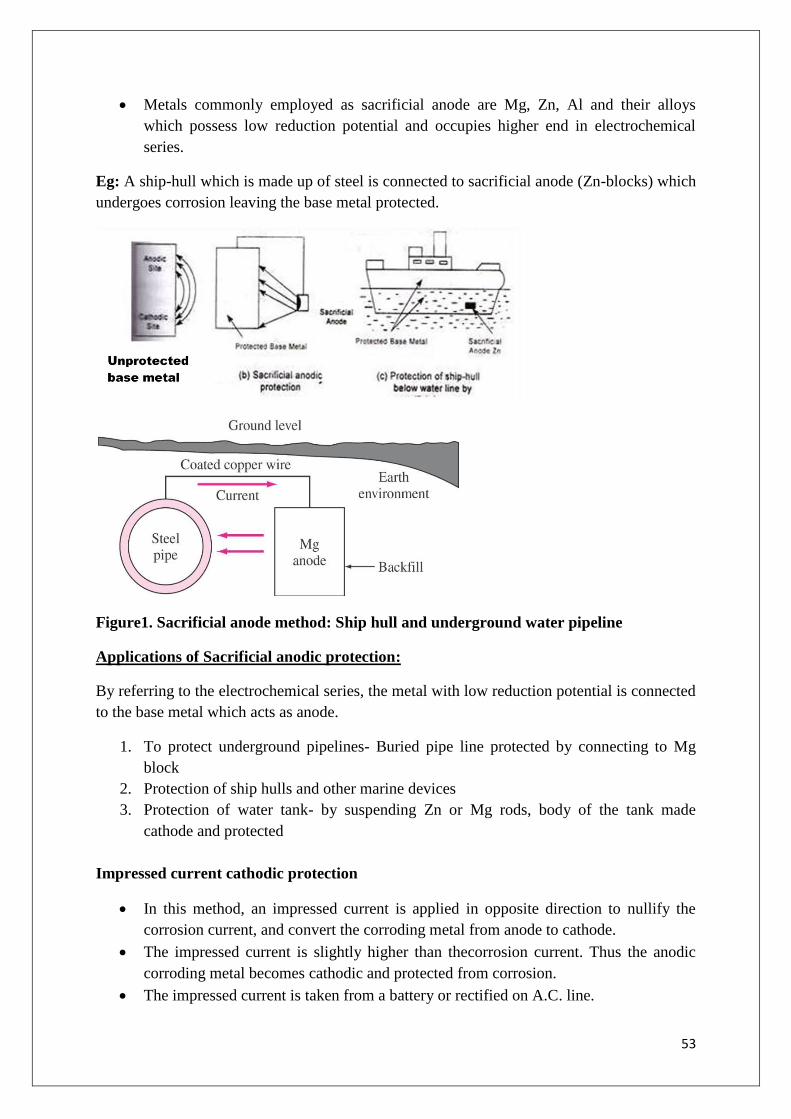
53
Metals commonly employed as sacrificial anode are Mg, Zn, Al and their alloys
which possess low reduction potential and occupies higher end in electrochemical
series.
Eg: A ship-hull which is made up of steel is connected to sacrificial anode (Zn-blocks) which
undergoes corrosion leaving the base metal protected.
Figure1. Sacrificial anode method: Ship hull and underground water pipeline
Applications of Sacrificial anodic protection:
By referring to the electrochemical series, the metal with low reduction potential is connected
to the base metal which acts as anode.
1. To protect underground pipelines- Buried pipe line protected by connecting to Mg
block
2. Protection of ship hulls and other marine devices
3. Protection of water tank- by suspending Zn or Mg rods, body of the tank made
cathode and protected
Impressed current cathodic protection
In this method, an impressed current is applied in opposite direction to nullify the
corrosion current, and convert the corroding metal from anode to cathode.
The impressed current is slightly higher than thecorrosion current. Thus the anodic
corroding metal becomes cathodic and protected from corrosion.
The impressed current is taken from a battery or rectified on A.C. line.

54
The metal to be protected is made cathode by connecting to an external battery (-ve
terminal)
The anode is usually insoluble anode like graphite, high silica iron, scrapiron,
stainless steel, or platinum. Usually a sufficient D.C current is passed on to the
insoluble anode kept in a black fill composed of coke or gypsum, so as to increase the
electrical contact with the surrounding soil.
In impressed current cathodic protection, electrons are supplied from anexternal cell,
so that the object itself becomes cathodic and not oxidized.
Applications:
The impressed current cathodic protection is used for the protection of water tanks,
water & oil pipe lines, transmission line towers etc.
b. Metallic coatings:
The surface of the base metal is coated with another metal (coating metal)is called metallic
coatings. Metallic coatings are broadly classified into anodic and cathodic coatings.
1. Anodic coating:The metal used for the surface coating is more anodic than the base metal
which is to be protected.

55
For example, coating of Al, Cd and Zn on steel surface are anodic because their
electrode potentials are lower than that of the base metal iron. Therefore, anodic
coatings protect the underlying base metal sacrificially.
The formation of pores and cracks over the metallic coating exposes the base metal
and a galvanic cell is formed between the base metal and coating metal. The coating
metal dissolves anodically and the base metal is protected.
2.Cathodic coating:
Cathodic coatings are obtained by coating a more noble metal (i.e. metals having
higher electrode potential like Sn, Au, Ag, Pt etc.) than the base metal. They protect
the base metal as they have higher corrosion resistance than the base metal due to
cathodic nature.
Cathodic coating protects the base metal only when the coating is uniform and free
from pores.
The formation of pores over the cathodic coating exposes the base metal (anode) to
environment and a galvanic cell is set up. This causes more damage to the base metal.
Cementation or Diffusion coatings:
This type of coating is obtained by heating the base metal in a revolving drum
containing powdered metal. Diffusion of the coating metal into the base metal takes
place, resulting in the formation of layers of alloy of varying composition. The layer
adjacent to base metal is solid solution and the outer layers are richer in coating metal.
Sherardising (developed by Shared Cowpercoles in 1890) is the process of
cementation, using zinc powder as coating material on the surface of iron. The iron
article to be coated is cleaned by acid pickling process and rotated for 2-3 hours in a
drum containing zinc dust at 350-370oC. During this process Zn diffuses into iron
forming Fe-Zn alloy at the junction of the base metal and coating metal and a thin
layer of zinc is deposited on the surface of iron. Sherardizing is used for coating small
steel articles like bolts, screws, nuts, threaded, washers, valves and gauge tools. The
advantage of Sherardizing is that the metal coating is uniform and there is no change
in the dimension of the article.
Colorizing: is a method of coating aluminium on the surface of iron by cementation.
The article is cleaned by sandblasting and heated in a drum tightly packed with a
mixture of aluminium powder and aluminium oxide together with traces of aluminium
chloride as flux in a reducing atmosphere of hydrogen. The layer formed has the
approximate composition of Al2Fe3 containing about 25% by weight of aluminium.
Colorizing is used for the protection of furnace parts
Chromising:The base metal is heated with a mixture of 55% Cr, and 45% Al powder
to 1300-1400oC for 3-4 hours. A mixture of volatile chromous chloride and hydrogen
with steel parts produce the protective layer of chromium diffused into iron surface.
Chromising is fairly and extensively used for the protection of turbine blades.

56
Siliconising: Coating silicon on the surface of molybdenum by cementation is called
siliconising.Silicon tetrachloride is used as a coating metal.
Methods of application of metallic coatings
1. Hot dipping:
Hot dipping process is applicable to the metals having higher melting point than the
coating metal.
It is carried out by immersing a well cleaned base metal in a bath containing molten
coating metal and a flux layer.
The flux cleans the surface of the base metal and prevents the oxidation of the molten
coating metal. Eg: Coating of Zn, Pb, Al on iron and steel surfaces.
The most widely used hot dipping processes are
(a) Galvanizing
(b) Tinning
a) Galvanizing:
Galvanizing is a process in which the iron article is protected from corrosion by
coating it with a thin layer of zinc.
It is the anodic protection offered by the zinc. In this process, at first iron or steel is
cleaned by pickling with dilute sulphuric acid solution at a temperature range of 60-
900C for 15 to 20 minutes. Therefore, it removes scale, rust and other impurities
present and then washed well in a water bath and dried.
Then after dipped in the bath containing molten zinc which is at 425-450oC. To
prevent it from oxide formation, the surface of bath is covered with an ammonium
chloride flux.Then the iron sheet is taken out which is coated with a thin layer of zinc.
To remove excess zinc, it is passed through a pair of hot rollers and then it is annealed
at a temperature of 450oC followed by cooling.
Applications: Galvanizing is widely used for protecting iron exposed to the
atmosphere (roofs, wire fences, pipes etc.) Galvanized metallic sheets are not used for
keeping eatables because of the solubility of zinc.
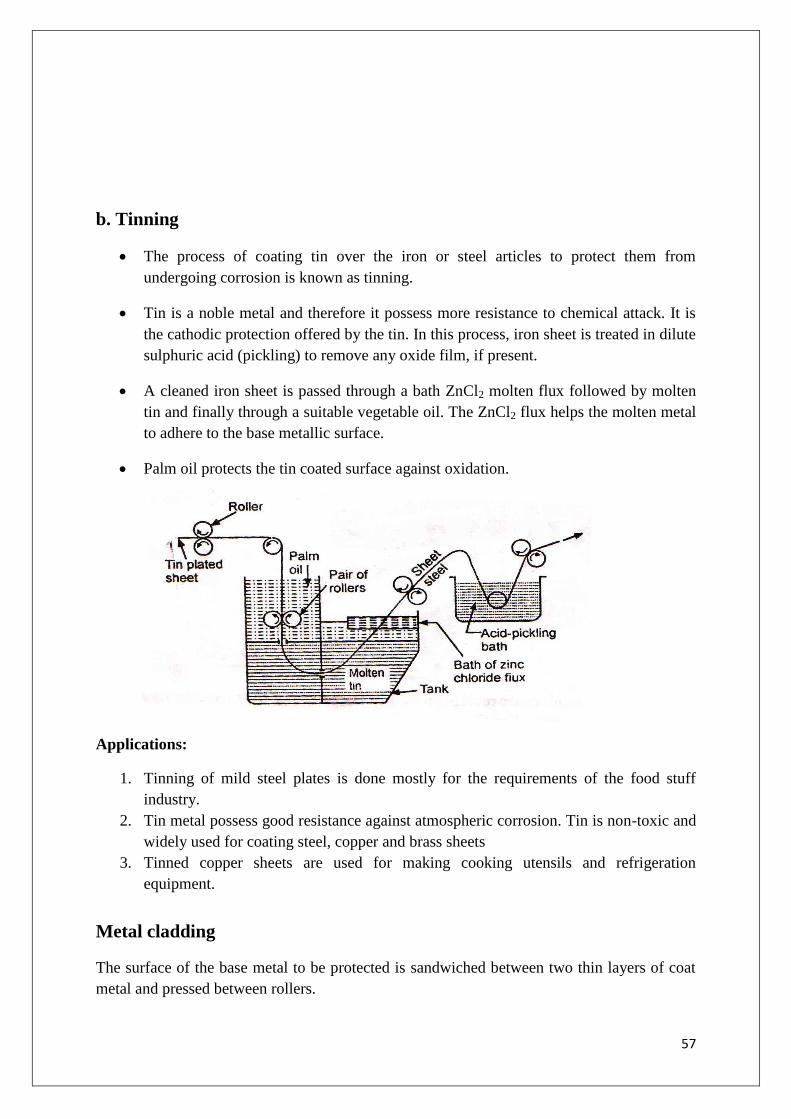
57
b. Tinning
The process of coating tin over the iron or steel articles to protect them from
undergoing corrosion is known as tinning.
Tin is a noble metal and therefore it possess more resistance to chemical attack. It is
the cathodic protection offered by the tin. In this process, iron sheet is treated in dilute
sulphuric acid (pickling) to remove any oxide film, if present.
A cleaned iron sheet is passed through a bath ZnCl2 molten flux followed by molten
tin and finally through a suitable vegetable oil. The ZnCl2 flux helps the molten metal
to adhere to the base metallic surface.
Palm oil protects the tin coated surface against oxidation.
Applications:
1. Tinning of mild steel plates is done mostly for the requirements of the food stuff
industry.
2. Tin metal possess good resistance against atmospheric corrosion. Tin is non-toxic and
widely used for coating steel, copper and brass sheets
3. Tinned copper sheets are used for making cooking utensils and refrigeration
equipment.
Metal cladding
The surface of the base metal to be protected is sandwiched between two thin layers of coat
metal and pressed between rollers.

58
Coating of a thin homogeneous layer of a coating metal on a base metal such that it
strongly binds permanently either on one side or on both sides under heat and pressure.
The finished product may be welded at the edges. The coat metal has to be anodic to the
base metal and only plain surfaces can be cladded.
This method is used for coating Al, Cr, Ni, Duralumin, etc. All corrosion-resistant metals
like Ni, Cu, Ag, Au & Pt and alloys like steel/nickel alloys can be used as cladding
materials.
Applications:
Duralumin is very light metal alloy used in aircraft industry which is cladded with
aluminum to get Alclad.
3.Electroplating:
Electroplating is the method of electro-deposition of metal by means of electrolysis
over surface of metals and alloys.
The base metal is first subjected to acid pickling to remove any scales, oxides etc. The
base metal is made as cathode of the electrolytic cell and the coating metal is made as
anode.
The two electrolytes are dipped in the electrolyte solution which contains the metal
ions to be deposited on the base metal.
When a direct current is passed from an external source, the coating metal ions
migrate towards cathode and get deposited over the surface of base metal in the form
of a thin layer.
Low temperature, medium current density, low metal ion concentration conditions are
maintained for better electro-plating.

59
Objectives of Electroplating
1. To increaseresistance to corrosion, chemical attack and wear resistance of the
plated metal
2. To improve physical appearance and hardness
3. To increase the decorative and commercial values of metals
4. To increase the strength of non-metals like plastics, wood and glass etc.
5. To make surface conductive by using light weight non-metallic materials like
wood and plastics
Electroplating-Copper plating:
For example for electroplating of copper on iron article the following are maintained
Electrolytic bath solution: CuSO4
Anode: Pure copper
Cathode: Base metal article
Temperature: 20-40oC (low temp for brighter and smooth surface)
Current density: 20-30 mA/cm2
When direct current is passed, the Cu2+
ions migrate to the cathode and deposit on the base
metal article.
Anode: Cu(s) →Cu2+
(aq) + 2e-
Cathode: Cu2+
(aq) + 2e-→ Cu(s)
Applications of electroplating
1. In internal combustion engines,an electroplated chromium coating not only avoids the
wear but also improves the running performances.
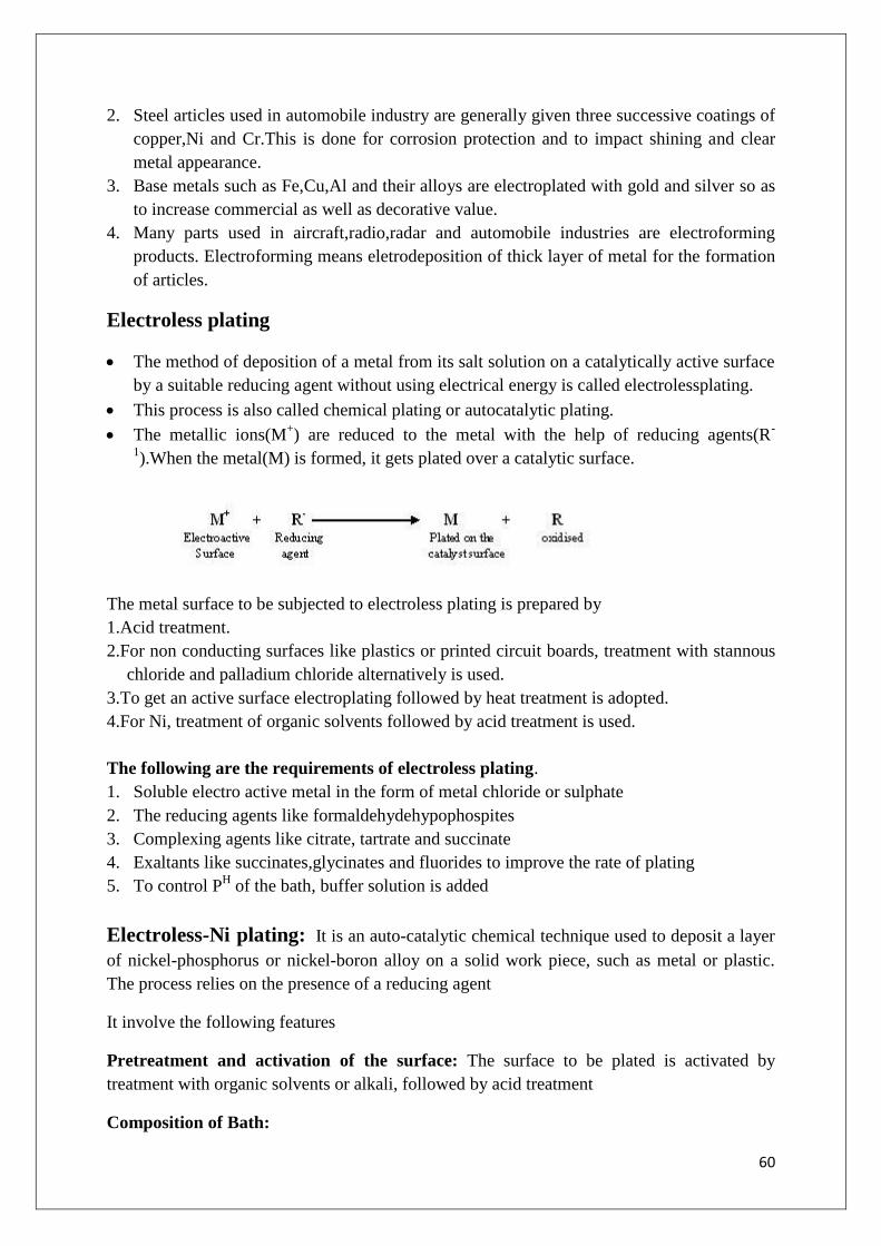
60
2. Steel articles used in automobile industry are generally given three successive coatings of
copper,Ni and Cr.This is done for corrosion protection and to impact shining and clear
metal appearance.
3. Base metals such as Fe,Cu,Al and their alloys are electroplated with gold and silver so as
to increase commercial as well as decorative value.
4. Many parts used in aircraft,radio,radar and automobile industries are electroforming
products. Electroforming means eletrodeposition of thick layer of metal for the formation
of articles.
Electroless plating
The method of deposition of a metal from its salt solution on a catalytically active surface
by a suitable reducing agent without using electrical energy is called electrolessplating.
This process is also called chemical plating or autocatalytic plating.
The metallic ions(M+) are reduced to the metal with the help of reducing agents(R
-
1).When the metal(M) is formed, it gets plated over a catalytic surface.
The metal surface to be subjected to electroless plating is prepared by
1.Acid treatment.
2.For non conducting surfaces like plastics or printed circuit boards, treatment with stannous
chloride and palladium chloride alternatively is used.
3.To get an active surface electroplating followed by heat treatment is adopted.
4.For Ni, treatment of organic solvents followed by acid treatment is used.
The following are the requirements of electroless plating.
1. Soluble electro active metal in the form of metal chloride or sulphate
2. The reducing agents like formaldehydehypophospites
3. Complexing agents like citrate, tartrate and succinate
4. Exaltants like succinates,glycinates and fluorides to improve the rate of plating
5. To control PH of the bath, buffer solution is added
Electroless-Ni plating: It is an auto-catalytic chemical technique used to deposit a layer
of nickel-phosphorus or nickel-boron alloy on a solid work piece, such as metal or plastic.
The process relies on the presence of a reducing agent
It involve the following features
Pretreatment and activation of the surface: The surface to be plated is activated by
treatment with organic solvents or alkali, followed by acid treatment
Composition of Bath:

61
Coating solution- NiCl2 solution
Reducing agent- Sodium hypophosphite (NaPO2H2.H2O)
Buffer- Sodium acetate
Complexing agent- Sodium succinate
Optimum PH- 4.5
Optimum temperature - 93
Reactions:
Ni2+
+ 2e- Ni (Cathode)
H2PO2- + H2O H2PO3
- + 2H
++2e
- (Anode)
Net Rexn: Ni2+
+ H2PO2- + H2O Ni +H2PO3
- + 2H
+
Properties
1. Electroless plated Ni objects has better corrosion resistance, deposits are pore free, hard
and wear resistant.
2. Due to excellent throwing power, this method can be applied on objects having intricate
shapes (eg; recesses, thread inside of tubing etc)
Applications:
Electroless Ni coating are used extensively in electronic components providing non magnetic
underlay in magnetic components
Advantages of Electroless plating:
1. Electrical energy is not required.
2. Even intricate parts (of irregular shapes) can be plated uniformly
3. There is flexibility in plating volume and thickness.
5. The process can plate recesses and blind holes with stable thickness.
6. Chemical replenishment can be monitored automatically.
7. Matte, semi bright or bright finishes can be obtained.
8. Plating on articles made of insulators (like plastics) and semiconductors can easily be
carried out.
Disadvantages of Electroless Plating:
1. Lifespan of chemicals is limited.
2. Waste treatment cost is high due to the speedy chemical renewal.
Applications:
1. It is commonly used in engineering coating applications where wear resistance, hardness
and corrosion protection are required.

62
2. Applications include oil field valves, rotors, drive shafts, paper handling equipment, fuel
rails, optical surfaces for diamond turning, door knobs, kitchen utensils, bathroom
fixtures, electrical/mechanical tools and office equipment
3. It is also commonly used as a coating in electronics printed circuit board manufacturing,
typically with an overlay of gold to prevent corrosion. This process is known as
electroless nickel immersion gold.
4. It is also used extensively in the manufacture of hard disk drives, as a way of providing an
atomically smooth coating to the aluminium disks, the magnetic layers are then deposited
on top of this film.
Surface coatings:
The application of surface coating is the common method to protect the surface of the metal
from the corroding environment. These surface coatings exhibit chemical inertness to
corrosive environment, adhesive properties and impermeable.
Organic surface coatings:
Organic surface coatings are applied over the metallic surfaces to prevent from the
corrosion.
Properties of Organic surface coatings.
Chemical inertness to the corrosive environment
Good surface adhesion
Impermeability to water, gases and salts
Eg. Paint
Paint:
Paint is a mechanical dispersion mixture of several constituents in a vehicle oil or drying oil.
The following are the constituents of paints and their functions.
Constituentsand Functionsof Paints
1. Pigment
It is a major constituent of the paint.
Provides desired colour to the paint
It protects the paint by reflecting harmful U.V radiation.
Gives strength and increases weather resistance of the film.
Examples: White- white lead, ZnO; Red- Red lead, Ferric oxide
2. Vehicle oil/ Drying oil
The drying oil contains a number of double bonds in their structure. The film formation and
drying of the film is the major function which takes place in the following way. When the
paint is applied in the form of a thin film the drying oil absorbs oxygen from air forming

63
peroxides, diperoxides, and hydroperoxides at the double bonds. These peroxides isomerise,
polymerise and condense to form a characteristic tough coherent hard elasticinsoluble
infusable highly cross linked structure polymer film.Hence the number of double bonds
increases the protective film forming capacity of the polymer increases
It forms the film forming constituent of the paint.
It acts as medium for the dispersion of various constituents.
It gives durability, adhesion and water proofness to the paint.
Examples: Sunflower oil, Mustard oil, Soyabean oil.
Drying of paint film
Drying oil (Gyceride of linolic acid) + O2 (from air)
Forms peroxides, hydroperoxides at the double bonds
Peroxides undergo isomerisation, polymerization and condensation
Form tough, hard elastic, insoluble, highly cross linked polymer film
3.Thinners
Reduces the viscosity and increases the elasticity of the paint film.
Enhances the dissolving the additives in vehicle medium.
Eg.Turpentine, kerosene, naphtha, mineralspirit, benzene
4. Driers
Driers are oxygen carrying catalysts.
They accelerate the drying of the paint film through oxidation, polymerization and
condensation.
Examples: Resinates, tungstates and naphthates of Pb, Zn and Co.
5. Extenders/ Fillers
Low refractive indices materials.
They reduce the cost and cracking nature of the paint film.
Increase durability
Serve to fill voids
Act as carrier pigment colour
Examples: BaSO4, gypsum, silica, china clay asbestos
6. Plasticizers

64
They provide elasticity to the film and minimize cracking.
Examples:Tributylphosphate,Triphenylphosphate
7. Anti skinning agents
The main function of the anti skinning agent is to prevent gelling and skinning of
paint film
Examples: Polyhydroxy phenols
UNIT-IIEngineering Materials
Polymers

65
Introduction:
Polymers form very important components in our daily life. The polymers are highly
useful in domestic, industrial & medical fields. The following are the reasons for the
extensive use of polymers.
1) Most of the polymers are non-toxic & safe to use
2) They have low densities (light in weight), so transportation of polymers will be easy
3) They possess good mechanical strength
4) They are resistant to corrosion and will not absorb moisture when exposed to the
atmosphere
5) They can function as good thermal & electrical insulators
6) They can be moulded and fabricated easily
7) They possess esthetic colors
But the limitations for the use of polymers are:
Some polymers are combustible.
The properties of polymers are time dependent
Some of them cannot withstand high temperatures.
It is also interesting to note that many carbohydrates, proteins & enzymes, DNA &
RNA are natural polymers.
Polymers can be defined as the large molecules (macro molecules) formed by the linking
together of large number of smaller molecules called monomers. (In Greek language „poly‟
means “many”&„mer‟ means “units”)
E.g.:- polyethyleneia polymer formed by linking together of a large number of ethylene
molecules
Polymerisation
nCH2 =CH2 ( CH2−CH2 ) n
Thus the repeated unit of polymer is called monomer. The number of repeating units in a
polymer chain is called degree of polymerization. For e.g. if 100 molecules of ethylene
polymerize to give the polymer chain, the degree of polymerization is 100.
Depending on the degree of polymerization, there are two types of polymers.
1. Oligopolymers: Those polymers whose degree of polymerization is less than 600 are
called oligopolymers.
2. High Polymers: When the degree of polymerization of a polymer is more than 600, it is
called high polymer.
Important terms:
Homopolymer:
Polymer made up of only one type of monomer. e.g.:- polyethylene, PVC

66
(-M-M-M-M-) n
Copolymer:
Polymer formed by the reaction between different monomers
eg: buna-s rubber(M1-M2 – M1 - M2 )n
Tacticity:
The arrangement of functional groups on carbon backbone of the polymer is called Tacticity.
It is manly divided into 3 types.
1) Isotactic polymers: Those polymers in which the functional groups are arranged on the
same side of polymer back bone are called isotactic polymers. Eg. PVC
2) Atactic polymers: When there is no regular arrangement of functional groups on the back
bone of the polymer chain, those polymers are called atactic polymers.
E.g.: PVC (Polyvinyl chloride)
3) Syndiotactic Polymers: The polymers with alternate arrangement of functional groups are
called syndiotactic polymers for e.g. PVC
Functionality:

67
For a substance to act as a monomer, it must have at least two reactive sites or bonding
sites. The number of reactive sites or bonding sites in a monomer is called functionality of
the monomer. If two reactive sites are there ina monomer then it is called bifunctional and
forms linear or straight chain polymers
A trifunctional monomer has three reactive sites and forms branched chain polymers.
A polyfunctional monomer has more than three reactive sites and forms three dimensional
network polymer
In olefins, the double bond can be considered as a site for free valencies. When the double
bond is broken, two single bonds become available for combination. Thus, ethylene is
considered to be bifunctional. Othe reactive groups are hydroxyl, acid, aminoacid, di-ol,
polyalcohols, di-amines, di-acids etc.
E.g.: Polyhexamethylene diamine( HN –(CH2)6 –NH )n no. of bonding sites are two. So it is
bifunctional polymer.
When the functionality of monomer is three (trifunctional), three dimensional net work polymer is
formed. E.g.:- Phenol
Synthetic high polymers classification:-
S.No Type Division
1. Structure/shape Linear Branched Cross linked
2. Tacticity Isotactic Syndiotactic Atactic
3. Physical state Amorphous Crystalline
4. Heat Thermoplastic Thermosetting
5. Conductance Insulators Conductors
6. Origin Natural Synthetic
7. Environment Biodegradable Durable
8. Monomer Polar Non-polar
9. Number of monomers Homo-polymer Co-polymer
10. Polymer chain Homo – chain Hetero – chain
11. Polymerization Addition condensation
Classification of Polymers:

68
Mechanism of polymerization (Types of polymerization)
Types of Polymerisation:
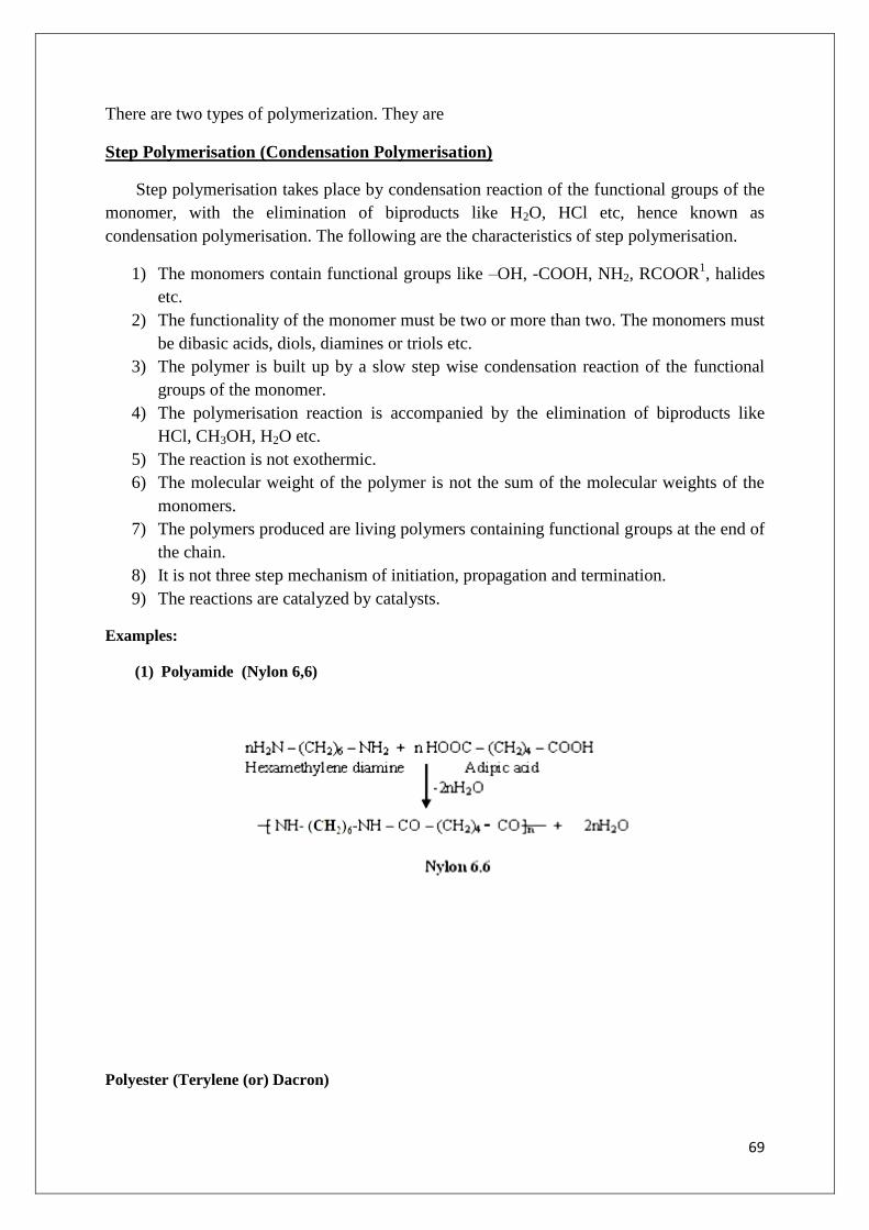
69
There are two types of polymerization. They are
Step Polymerisation (Condensation Polymerisation)
Step polymerisation takes place by condensation reaction of the functional groups of the
monomer, with the elimination of biproducts like H2O, HCl etc, hence known as
condensation polymerisation. The following are the characteristics of step polymerisation.
1) The monomers contain functional groups like –OH, -COOH, NH2, RCOOR1, halides
etc.
2) The functionality of the monomer must be two or more than two. The monomers must
be dibasic acids, diols, diamines or triols etc.
3) The polymer is built up by a slow step wise condensation reaction of the functional
groups of the monomer.
4) The polymerisation reaction is accompanied by the elimination of biproducts like
HCl, CH3OH, H2O etc.
5) The reaction is not exothermic.
6) The molecular weight of the polymer is not the sum of the molecular weights of the
monomers.
7) The polymers produced are living polymers containing functional groups at the end of
the chain.
8) It is not three step mechanism of initiation, propagation and termination.
9) The reactions are catalyzed by catalysts.
Examples:
(1) Polyamide (Nylon 6,6)
Polyester (Terylene (or) Dacron)

70
Chain Growth Polymerization: (Addition Polymerization)
A chain polymerisation is a reaction that yields a polymer product which is the exact
multiple of monomers. Thus the mechanism is also called addition polymerisation. The
following are the characteristics.
1) The functionality of the monomer is a double bond and it is bifunctional.
2) The polymerisation takes place by self-addition of the monomer molecules to each
other through a chain reaction.
3) No biproducts like H2O,CH3OH etc. are produced.
4) The polymer has the same chemical composition as that of monomer.
5) The mechanism is carried out in three steps, i.e. initiation, propagation and termination.
6) The mechanism is rapid.
7) The conversion of Π bond to 𝜍 bond takes place during the polymerisation, liberating
20 k.cal/mole of energy. Hence highly exothermic reaction.
8) An initiator is required to start the polymerisation reaction.
Mechanism of chain growth polymerization:
Addition polymerisation is classified into
(1) Free radical polymerization
(2) Cationic addition polymerization
(3) Anionic addition polymerization

71
(4) Coordination polymerization
The reactive species free radical, cation & anion undergo initiation, propagation &
termination steps.
Free radical additional polymerization: During polymerization of alkenes the presence of a
small amount of an initiator is necessary.Commonly known initiators are peroxides.
a) Chain initiation step:- Initiators are unstable compounds and undergoes homolytic
fission to produce free radicals which react with 𝜋 e‟s of the monomer to produce
monomer free radical.
H2O2 is good initiator for free radical chain polymerization.
b) Propagation:- The monomer free radical chain reacts with a number of monomers rapidly
resulting the chain growth with free radical site at the end of the chain producing a living
polymer.
By adding fresh monomer to the living polymer with free radical site, again chain growth
starts. Hence it is known as living polymer.

72
c) Termination:(To stop chain growth) The reaction is terminated by the recombination of
final free radicals producing dead polymer
Cationic chain polymerization:-
The heterolytic fission of the initiator results in cationic & anionic chain polymerization.
Monomers with electron releasing substituent‟s (CH3, -OC6H5, -C6H5) undergo cationic
polymerization in the presence of Lewis acid (e- acceptor) e.g.:- BF3, AlCl3, H2SO4 etc.The
polymerization proceeds through the formation of the carbocation and chain growth is
accompanied with the transfer of the positive charge along with the polymer chain.
Mechanism
a) Initiation:- The proton produced add to the multiple bond of the monomer molecule
and forms the monomer carbocation.
b) Propagation:The monomer carbocation attacks the 𝛱 e-s of the other monomer
resulting the chain growth with carbocation at the end of the chain.
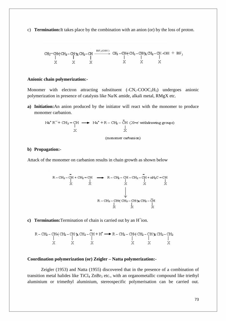
73
c) Termination:It takes place by the combination with an anion (or) by the loss of proton.
Anionic chain polymerization:-
Monomer with electron attracting substituent (-CN,-COOC2H5) undergoes anionic
polymerization in presence of catalysts like Na/K amide, alkali metal, RMgX etc.
a) Initiation:An anion produced by the initiator will react with the monomer to produce
monomer carbanion.
b) Propagation:-
Attack of the monomer on carbanion results in chain growth as shown below
c) Termination:Termination of chain is carried out by an H+ion.
Coordination polymerization (or) Zeigler – Natta polymerization:-
Zeigler (1953) and Natta (1955) discovered that in the presence of a combination of
transition metal halides like TiCl4 ZnBr3 etc., with an organometallic compound like triethyl
aluminium or trimethyl aluminium, stereospecific polymerisation can be carried out.

74
Combination of metal halides and organometallic compounds are called Zeigler Natta
catalysts. Here the mechanism is same as anionic addition polymerisation.
Difference between condensation and addition polymerisation
Condensation polymerisation Addition polymerisation
(1) It is also known as step growth
polymerisation
(1) It is also known as chain growth
polymerisation
(2) It takes place in monomers having reactive
functional groups
(2) It takes place only in monomers having
multiple bonds.
(3) It takes place with elimination of simple
molecule like H2O,NH3,HCl etc.
(3) It takes place without elimination of simple
molecule.
(4) Repeating units of monomers are different (4) Repeating units& monomers are same
(5) The polymer is formed in gradual steps (5) Reaction is fast and polymer is formed at
once
(6) The molecular mass of polymer increases
throughout the reaction
(6) There is very little change in the molecular
mass throughout the reaction
(7) Product obtained may be
thermosetting/thermoplastic
(7) Products obtained are thermoplastic
(8) E.g.: Bakelite, polyester, polyamides etc. (8) E.g: Polyethylene, PVC, polystyrene.
Plastics:Plastics are the polymers characterized by the property of plasticity (permanent
deformation in structure on applying some stress/force). They can be moulded to desired
shape when subjected to heat and pressure in the presence of catalyst.
Plastics as engineering materials:
Advantages of plastics over other engineering materials
1. Low fabrication cost, low thermal & electrical conductivities, high resistance to
corrosion & solvents.
2. The stress – strain relationship of plastics is similar to that of the metals.
3. Plastics reduce noise & vibration in machines.
4. Plastics are bad conductors of heat and are usedto make handles for hot objects, most
plastics are inflammable.
5. Plastics are electrical insulators & find large scale use in the electrical industry.
6. Plastics are resistance to chemicals.
7. Plastics are clear & transparent so they can be given beautiful colours.
Types of Plastic:(1) Thermoplastics
(2) Thermosetting plastics

75
Difference between Thermoplastic & Thermoset resins:
Thermoplastic Resins Thermoset Resins
1. These resins become soft on heating and
rigid on cooling by regaining original
properties. These can be reshaped and used.
1. They do not soften on heating and become
hard. On prolonged heating they decompose
and cannot get back its structure. Hence
cannot be reshaped and used.
2. The heating and cooling do not alter the
chemical nature of these resins but involves
changes in physical nature.
2. These resins are permanent setting resins.
3.They are formed by addition
polymerization
3.They are formed by condensation
polymerization.
4. Small molecular weight compounds with
linear structures.
4. Large molecular weight compounds with
three dimensional networks.
5. They consist of long chain linear polymer
with weak secondary vandarwaal‟s forces of
attraction in between them.
5. Highly cross-linked structure strong
covalent bonds are responsible for strength.
6. They soften on heating readily because
the secondary force of attraction between
the individual chain can break easily by
heat, pressure or both
6.The bonds retain their strength on heating,
hence do not soften on heating
7. These plastic can be reclaimed from
waste
7. Cannot be reclaimed from waste
8. They are soft, weak and less brittle 8. They are hard, strong and more brittle
9.These resins are usually soluble in organic
solvents
9. Due to strong bonds and cross links, they
are insoluble in all organic solvents.
10. Curing by cooling
Eg: PE, PS, PVC, Teflon
10. By applying heat and pressure
Eg: Bakelite, Polyester(Terylene)and
silicones
Compounding & Fabrication of plastics:-
Compounding of plastics:Compounding of plastics may be defined as the mixing of
different materials like plasticizers, fillers or extenders, lubricants, stabilizers and pigments to
the thermoplastic & thermosetting resins to increase their useful properties like strength,
toughness, etc.
Resins have plasticity or binding property, but need other ingredients to be mixed with them
for fabrication into useful shapes.
Ingredients used in compounding of plastics are
(1) Resins (2) Plasticizers (3) Fillers (4) Pigments (5) Stabilizers
76
Resins: The product of polymerisation is called resins and this forms the major portion of the
body of plastics. It is the binder, which holds the different constituents together.
Thermosetting resins are usually, supplied as linear–polymers of comparatively low
molecular weight, because at this stage they are fusible and hence, mouldable. The
conversion of this fusible form into cross-linked infusible form takes place, during moulding
itself, in presence of catalysts etc.
Plasticizers:Plasticizers are substances added to enhance the plasticity of the material and to
reduce the cracking on the surface.Plasticizers are added to the plastics to increase the
flexibility & toughness. Plasticizers also increase the flow property of the plastics.
e.g.:- Tricresyl phosphate, Dibutyl oxalate, Castor oil
Fillers (or) extenders:Fillers are generally added to thermosetting plastics to increase
elasticity and crack resistance.Fillers improve thermal stability, strength, non combustibility,
water resistance, electrical insulation properties & external appearance.
E.g.Mica, cotton, carbon black, graphite, BaSO4 etc.
Lubricants:
Lubricants make moulding of plastic easier
They impart flawlss, glossu finish to the products
They prenent moulded article from sticking to the frabrication equipment
E.g. Waxes, olis, stearates, oleates, and soap
Catalyst or accelerators:
They accelerate the polymerization of fusible resins during moulding operation into cross
linked infusible form for thermosetting resins.
E.g. Bezoylperoxide, hydrogenperoxide,metals like copper and lead and ZnO.
Dyes and pigments:These are added to impart the desired colour to the plastics and give
decorative effect.
e.g.:- Lead chromate (yellow), ferrocyanide (blue)
Stabilizers:Stabilizers are used to improve the thermal stability of plastics, e.g. PVC. At
moulding temperature, PVC undergoes decomposition & decolourisation. So during their
moulding, stabilizers are used. E.g. white lead, lead chromate etc.
Fabrication of plastics:Many methods of fabricating plastics into desired shaped articles are
employed. This production of plastics is known as fabrication of plastics.
The methods, usually depends upon the types of resins used i.e., whether thermosetting or
thermoplastic.
Compression Moulding:It is used for both thermosetting and thermoplastic resins. A desired
quantity of compounding plastic resin is filled in the cavity present in the bottom mould, the

77
top mould and the bottom mould are capable of being moved relative to each other. When
heat & pressure are applied according to specifications, the cavities get filled with fluidized
plastic. The two moulds are closed tightly and curing is done either by heating in case of
thermo set plastic resins or by cooling in case of thermoplastic resins. After curing the
moulded article is taken out by opening the mould. E.g. dinner set handles of electrical
appliances, crockery etc.
Injection Moulding:It is used for thermoplastic resins. The moulded plastic powder is heated
in a cylinder and injected at a controlled rate into the locked mould by means of screw
arrangement.
The mould is kept cold so that the hot plastic becomes solid due to the phenomenon of
curing. After sufficient curing, the mould is opened to allow the ejection of moulded object.
The advantage of this process is a high rate of production.
E.g.:- bottle caps, pocket combs, containers etc.
Chemistry of some important thermoplastic & thermoset resins:-
(1) Polyvinyl chloride (PVC):The monomer used for the manufacture of PVC is vinyl chloride.
Vinyl chloride is prepared by treating acetylene with HCl at 60-800Cand in presence of a metal
oxide catalyst

78
Polyvinyl chloride is produced by heating vinyl chloride in presence of benzyl peroxide or
H2O2.
Properties:
PVC is a colourless, non-inflammable and chemically inert powder
It has specific gravity 1.33 and melting point 148oC
Resistant to atmospheric conditions like O2, CO2 and moisture
They are rigid and flexible
It has resistance to light
Applications:
There are two kinds of PVC plastics
Rigid PVC(Unplasticized PVC): It is chemically inert & non-inflammable powder having a
high softening temperature of 1480C.
This PVC is used for making safety helmets, refrigerator components, tyres, cycle & motor
cycle mud guards.
Plasticized PVC:It is produced by mixing plasticizers like dibutyl phthalate with PVC resin
uniformly. It is used for making rain coats, table-cloths, handbags, curtains & electrical
insulators, radio, T.V components. All PVCshoes for beach wear.
2) Teflon (polytetrafluoro ethylene):Teflon is obtained by polymerization of
tetrafluoroethylene under pressure in presence of benzoyl peroxide as catalyst

79
Properties:
Teflon is also known as Fluon. Due to the presence of highly electronegative fluorine atoms,
teflon has got:
High melting point (350oC)
The strong attractive force is responsible for high toughness & high chemical resistance
towards all chemicals except hot alkali metal & hot fluorine.
High density 2.1-2.3gm/cc
It is a very good electrical insulator
It possess very good abrasion resistance
Engineering applications:
It is used in making seals & gaskets, which have to withstand high temperature.
It is also used for insulation of electrical items and for making non-sticky surface coating,
particularly for cooking utensils.
Teflon used as insulating material for motors, transformers, cables, wires, fitting etc.,
Some examples for Thermosetting Resins:
Bakelite(or) Phenol Formaldehyde Resin:
Bakelite is an important thermoset resin named after the scientist Bakeland, who synthesized
this resin in the year 1909
The condensation reaction of phenol & formaldehyde in the presence of acid or alkali catalyst
and at proper temperature produces the phenol formaldehyde resin or Bakelite resin.
I Stage: The initial reactions of phenol & formaldehyde in presence of acid or alkali produces
mono, di, trimethylol phenols depending on the phenol formaldehyde ratio (P/F ratio)

80
II Stage: Novolac Formation
When phenol and formaldehyde are heated in excess of phenol, with an acid catalyst, such as
HCl, H2SO4, a linear polymer is formed which is thermoplastic in nature and is known as
“Novolac”.
III Stage: Bakelite
On further heating, in the presence of hexamethylenetetramine, Novalac produces 3D-cross
linked thermosetting polymer which is known as “Bakelite”
Properties:
(1) Bakelites are hard, rigid and withstand very high temperatures
(2) They have excellent heat and moisture resistance
(3) They have good chemical resistance, resistance to acids, salts and many organic solvents,
but it is attached by alkalis due the presence of –OH group
(4) They have good abrasion resistance
(5) They have electrical insulation characteristics
(6) It is a good anionic exchanging resin, exchange –OH group with other anion
(7) Low molecular weight grades have excellent bonding strength and adhesive properties.
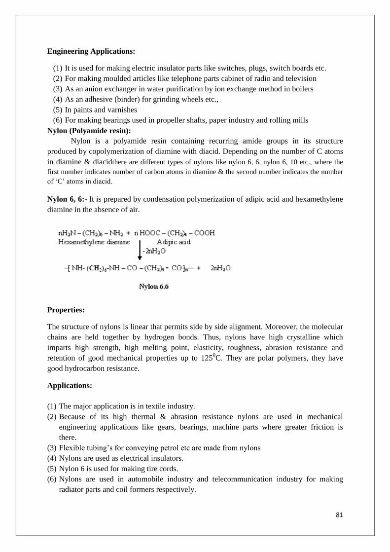
81
Engineering Applications:
(1) It is used for making electric insulator parts like switches, plugs, switch boards etc.
(2) For making moulded articles like telephone parts cabinet of radio and television
(3) As an anion exchanger in water purification by ion exchange method in boilers
(4) As an adhesive (binder) for grinding wheels etc.,
(5) In paints and varnishes
(6) For making bearings used in propeller shafts, paper industry and rolling mills
Nylon (Polyamide resin):
Nylon is a polyamide resin containing recurring amide groups in its structure
produced by copolymerization of diamine with diacid. Depending on the number of C atoms
in diamine & diacidthere are different types of nylons like nylon 6, 6, nylon 6, 10 etc., where the
first number indicates number of carbon atoms in diamine & the second number indicates the number
of „C‟ atoms in diacid.
Nylon 6, 6:- It is prepared by condensation polymerization of adipic acid and hexamethylene
diamine in the absence of air.
Properties:
The structure of nylons is linear that permits side by side alignment. Moreover, the molecular
chains are held together by hydrogen bonds. Thus, nylons have high crystalline which
imparts high strength, high melting point, elasticity, toughness, abrasion resistance and
retention of good mechanical properties up to 1250C. They are polar polymers, they have
good hydrocarbon resistance.
Applications:
(1) The major application is in textile industry.
(2) Because of its high thermal & abrasion resistance nylons are used in mechanical
engineering applications like gears, bearings, machine parts where greater friction is
there.
(3) Flexible tubing‟s for conveying petrol etc are made from nylons
(4) Nylons are used as electrical insulators.
(5) Nylon 6 is used for making tire cords.
(6) Nylons are used in automobile industry and telecommunication industry for making
radiator parts and coil formers respectively.

82
Conducting polymers:
Most polymeric materials are poor conductors of electricity because of non-availability of
large number of free electrons. Those polymers which conduct electricity are called
conducting polymer. The conduction of polymers is due to unsaturation or due to the
presence of externally added ingredients to them. Conducting polymers are classified
intofollowing types.
(A) Intrinsic conducting polymers:-
These polymers have extensive conjugation in the backbone which is responsible for
conductance.
Conducting polymers having conjugation:
Polymers have alternating double and single bond along the polymer chain and each
carbon atom is in sp2 hybridized state. One valence 𝜋e
- on carbon is in Pz orbital. The orbitals
of conjugated 𝜋e-s overlap the entire backbone of the polymer and result in the formation of
valence bands & conduction bands.
The valence band is filled band and conduction band is empty. When the energy gap between
these is low, the e-s from valence band are excited to conduction band become mobile
throughout the polymer and show conductivity.
E.g.trans-polyacetylene, polyaniline
Doped conducting polymers:
The conducting polymers having 𝜋e-s in their backbone can easily be oxidized or reduced because
they possess low ionization potential and high electron affinities. Hence their conductance can be
increased by introducing a positive charge or negative charge on polymer backbone by oxidation or

83
reduction. This process is similar to semiconductor technology and is called doping. Doping is
again two types.
(1) Creating a positive site on polymer backbone called p-doping.
(2) Creating a negative site on the polymer backbone called n-doping.
Oxidation process is done by adding some alkali metals or e- acceptor and conductivity is
enhanced by p-doping. Reduction process is done by adding reducing agents or electron
donor and conductivity is enhanced by n-doping.
p-doping:
p-doping is done by oxidation of a conducting polymer like polyacetylene with a Lewis acid
or iodine vapour. This is called oxidative doping.
During oxidation process the removal of 𝜋electrons from polymer backbone lead to the
formation of a delocalized radical ion called polaron having a hole in between valence
band and conducting band.
The second oxidation of the polaron results in two positive charge carriers in each chain
called bipolaron, which are mobile because of delocalization.These delocalized charge
carriers are responsible for conductance when placed in electric field.
n-doping:
n-doping is carried out by reduction process by the addition of an electron to polymer
backbone by using reducing agents like sodium napthalide Na+(C10H8)
-. Formation of
polaron, bipolaron takes place in two steps, followed by recombination of radicals, which
yields two charge carriers on the polyacetylene chain responsible for conduction
The electron added to polyacetylene by reductive doping doesn‟t go into the conducting band
but goes into an intermediate electronic state within the band gap of radical anion.
Bipolaroncontains electrons in the energy levels residing in the band gap

84
(B)Extrinsic conducting polymers:-
The conductivity of these polymers is due to the presence of externally added ingredients
in them. These polymers are two types.
Conducting element filled polymers:-
The polymers acting as a binder to hold the conducting element such as carbon black,
metallic fibers, metallic oxides etc., minimum concentration of filler is added so that the
polymer starts conducting. This minimum concentration of conductive filler is called
percolation threshhold. At this concentration of filler, a conducting path is formed in
polymeric material. The most preferred filler is the special conducting grade C-black has very
high surface area, more porosity and more of a filamentous properties.
Advantages:-
(1) These polymers are low cost polymers
(2) They are light in weight and mechanically durable.
(3) These polymers are strong with good bulk conductivity.
(4) They are fabricated very easily to any design.
Blended conducting polymers:- These are the polymers, which are obtained by mixing a
non-conducting polymer with a conducting polymer either physically or chemically. These
blended conducting polymers have better physical, chemical and mechanical properties.
Applications of conducting polymers:-
(1) The conducting polymers are used in rechargeable batteries, small in size (bottom
size), producing current density up to 50mA/cm2
(2) Conducting polymers are also used for making analytical sensors for PH, O2,
NOx,SO2,NH3 and glucose
(3) The conducting polymers are used for making ion exchangers. These membranes
made of conducting polymers show selective permeability for ions and gases hence
they are used for control release of drug.
(4) The conducting polymers are used for making electronic displays and optical fibres
(5) They are used for cancer chemotherapy
(6) The conducting polymers are applicable in photovoltaic devices, LED‟s and data
storage.
The role of polyacetylenes as conducting polymers:-
The conjugated polymer with simplest chemical structure is poly acetylene. Polymerization
of acetylene with Zeigler Natta catalysts gives polyacetylene which in its used form with
increasing temperature gets transformed to more stable transform. This polymer is infusible,
insoluble and becomes brittle on exposed to air. The conductivity of polyacetylene is
magnified by doping.
Exposure of the film to dry ammonia gives polymer with conductivity of 103Scm
-1,
controlled addition of p-doping agents like AgF5, Br2, I2, or HClO4 could move to still higher
conductivities.

85
Conducting Mechanism:-
The semi conducting polyacetylene (CH2)n has a typical carbon backbone structure.
The localized e-s in „S‟ bonds form the back bone of the polymer chain and dominate the
medicinal properties, while the e-s in the 𝜋 bonds are delocalized along the chain and
responsible for the electrical & optical properties of a conjugated polymer.
The σ bonds form completely filled low lying energy bands that have larger energy gap than
the 𝜋bond e-s. Before passing current, the e
-s can flow along the molecules and one or more
e-s have to be removed or inserted. In presence of an electric field, the e
-s constituting bonds
can move along the molecular chain.
Doping of polyacetylene:
Polyacetylene possesses alternate single and double bonds that give rise to mobile 𝜋-e-s when
doped, i.e., become anisotropic metallic conductors.
There are two types of doping,
They are: (1) Oxidation with halogen (p-doping)
(2) Reduction with alkali (n-doping).
The role of polyanilines as conducting polymer:
Polyaniline is conjugated polymer and is reactive.Polyaniline is considered as an organic
metal. Its specific conductivity is 55Scm-1
.
Polyaniline is transparent in thin layers. In conducting state it is green. It turns red under
reducing conditions and blue under oxidizing or basic ones.
Polyaniline is a stable conducting polymer. It has wide range of conductivity.
It shows multi-colour electrochromism and chemical sensitivity.
It can be synthesized chemically or electro chemically as a bulk powder or film. It was
prepared by the anodic oxidation of aniline in H2SO4.
Its conductivity is due to conjugated p-bond systems formed by the overlapping of carbon
p-orbital and alternating c-c bond lengths extending over large number of recurring
monomer units.
Its pzorbitals of nitrogen and carbon rings are also part of the conjugated system.
Conjugated double bonds permit the e- mobility throughout the molecule due to
delocalized e-s.
It has a conjugated double bond structure, i.e., benzenoid ring between the quininoid
imines and the benzenoid amide structure.

86
Preparation of Polyaniline:-
Polyaniline is prepared by the redox polymerization of aniline in protonic and aqueous
solution in the presence of ammonium per disulphate as oxidant.
It can be regarded as conducting polymer under certain stimulating conditions like UV light,
heat or addition of a suitable dopant to the polymer.
Doping of polyaniline:-
It can be made conductive by p-type doping or n-type doping of polymer.
In undoped state, it is a poor semi-conductor.
Properties:-
Due to the presence of extended σ – bond system of conjugated polymers, it is highly
susceptible to chemical & electrochemical oxidation or reduction.
Electronically conducting polymers are extensively conjugated molecules and
possess specially delocalized band line structure.
Disadvantages:-
(1) Polyaniline decomposes prior to melting. Hence it is difficult to process.
(2) It is insoluble in common solvents except strong acid
(3) It has poor mechanical properties.
Applications:-
Polyaniline is used for corrosion protection, sensors, smart windows, printed circuit
boards, conductive fabrics and conductive pipes for explosives.

87
Rubbers:
Those polymers which posses the property of elasticity is called rubber. Temporary
deformation in structure on applying some stress is more than 600e.u.When stress is applied
polymers chains get partially aligned with respect to another, thereby causing crystallization,
temporary deformation which makes the polymer stiff. On releasing the stress the chains get
reverted back to their original coiledstate.The elasticity of rubber is due to its coiled helix
structure
Natural Rubber:
Natural Rubber is a high molecular weight hydrocarbon polymer represented by the
formula (C5H8)x. It is obtained from a milk emulsion called latex by tapping the bark of the
tree “Hevea brasiliensis.” The main composition of natural rubber is polyisoprene which is
in the form of long coiled chains. The isoprene units polymerise to form rubber. Isoprene in
natural rubber exits in two geometrical isomeric forms, cis and trans
cis-polyisopreneis present in Natural rubber
trans-polyisoprene is present in Gutta percha rubber
Processing of Natural Rubber:-
By cutting the bark of rubber tree the milky colloidal rubber milk is obtained. The main constituent
of rubber latex is 25-45% of rubber and the remaining are water, protein & resinous materials. The
rubber latex is coagulated by using 5% acetic acid and made in to sheets. The rubber sheets are cured
under mild heat and then subjected to further processing.
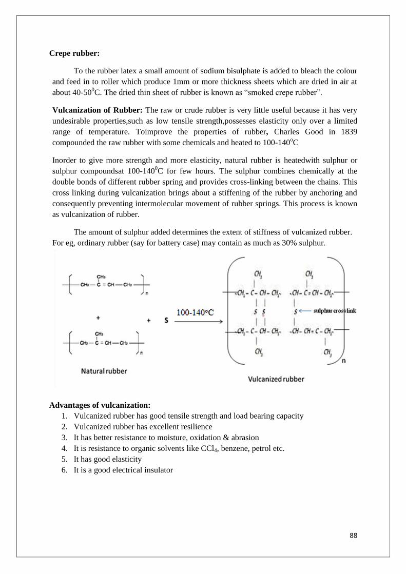
88
Crepe rubber:
To the rubber latex a small amount of sodium bisulphate is added to bleach the colour
and feed in to roller which produce 1mm or more thickness sheets which are dried in air at
about 40-500C. The dried thin sheet of rubber is known as “smoked crepe rubber”.
Vulcanization of Rubber: The raw or crude rubber is very little useful because it has very
undesirable properties,such as low tensile strength,possesses elasticity only over a limited
range of temperature. Toimprove the properties of rubber, Charles Good in 1839
compounded the raw rubber with some chemicals and heated to 100-140oC
Inorder to give more strength and more elasticity, natural rubber is heatedwith sulphur or
sulphur compoundsat 100-1400C for few hours. The sulphur combines chemically at the
double bonds of different rubber spring and provides cross-linking between the chains. This
cross linking during vulcanization brings about a stiffening of the rubber by anchoring and
consequently preventing intermolecular movement of rubber springs. This process is known
as vulcanization of rubber.
The amount of sulphur added determines the extent of stiffness of vulcanized rubber.
For eg, ordinary rubber (say for battery case) may contain as much as 30% sulphur.
Advantages of vulcanization:
1. Vulcanized rubber has good tensile strength and load bearing capacity
2. Vulcanized rubber has excellent resilience
3. It has better resistance to moisture, oxidation & abrasion
4. It is resistance to organic solvents like CCl4, benzene, petrol etc.
5. It has good elasticity
6. It is a good electrical insulator
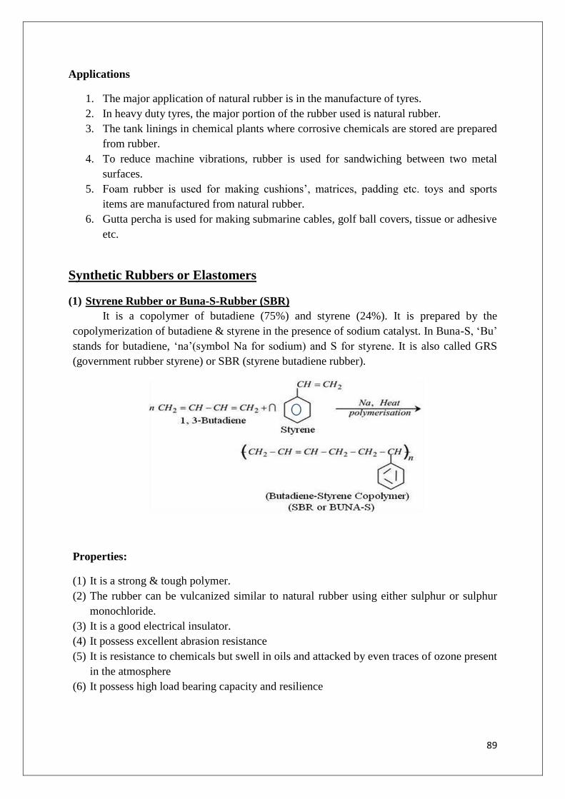
89
Applications
1. The major application of natural rubber is in the manufacture of tyres.
2. In heavy duty tyres, the major portion of the rubber used is natural rubber.
3. The tank linings in chemical plants where corrosive chemicals are stored are prepared
from rubber.
4. To reduce machine vibrations, rubber is used for sandwiching between two metal
surfaces.
5. Foam rubber is used for making cushions‟, matrices, padding etc. toys and sports
items are manufactured from natural rubber.
6. Gutta percha is used for making submarine cables, golf ball covers, tissue or adhesive
etc.
Synthetic Rubbers or Elastomers
(1) Styrene Rubber or Buna-S-Rubber (SBR)
It is a copolymer of butadiene (75%) and styrene (24%). It is prepared by the
copolymerization of butadiene & styrene in the presence of sodium catalyst. In Buna-S, „Bu‟
stands for butadiene, „na‟(symbol Na for sodium) and S for styrene. It is also called GRS
(government rubber styrene) or SBR (styrene butadiene rubber).
Properties:
(1) It is a strong & tough polymer.
(2) The rubber can be vulcanized similar to natural rubber using either sulphur or sulphur
monochloride.
(3) It is a good electrical insulator.
(4) It possess excellent abrasion resistance
(5) It is resistance to chemicals but swell in oils and attacked by even traces of ozone present
in the atmosphere
(6) It possess high load bearing capacity and resilience

90
Applications:
(1) Major application of styrene rubber is in manufacture of tyres.
(2) It is used in foot wear industry for making shoe soles and footwear components
(3) It is also used for making wires and cable, insulators.
(4) It is also used for the production of floor files, tank linings in chemical industries.
(2) Butyl rubber (GR–I or Polyisobutylene):
Butyl rubber is also is also known as GR-I (Government Rubber Isobutene) produced by
copolymerization of isobutene (98%) with butadiene (2%) or isoprene in presence of
anhydrous AlCl3.
Properties:-
1. The rubber shows extremely low permeability to air and other gases.
2. It also possesses resistance to heat, mineral acids, polar solvents etc.
3. It can be vulcanized with S, but it possesses low hardness due to less number of double
bonds.
Applications:
Butyl rubber is used for making cycle and automobile tubes.
It is also used for making hoses, conveyor belts, insulating cable, tank linings etc.
(3) Thiokol rubber (or) polysulphide rubber (or) GR-P rubber:
Thiokol rubber is prepared by the condensation polymerization of sodium polysulphide
(Na2Sx) and ethylene dichloride. In this elastomers, sulphur forms a part of the polymer
chain.

91
Properties:-
(1) These rubbers possess strength and impermeability to gases.
(2) This rubber cannot be vulcanized because its structure is not similar to natural rubber
and it cannot form hard rubber.
(3) It possesses extremely good resistance to mineral oils, fuels, oxygen, solvents, ozone &
sunlight.
Applications:-
(1) Fabrics coated with thiokol are used for barrage balloons
(2) It is mainly used as solid propellant fuel for rocket
(3) It is also used for making gaskets, hoses, cable linings, tank linings etc.
(4) It is also used for printing rolls
(5) Containers for transporting solvents
(6) Diaphragms and seats in contact with solvents.
Fibers:
Fibers are a class of materials that are continuous filaments or discrete elongated
pieces. They are crystalline, present in both plants & animals.
They are used for making textiles, ropes, utilities, strings etc.
These are of two types
(1) Natural Fibers
(2) Synthetic fibers
1. Natural fibers: Produced by plants, animals & geological materials.
a. Vegetable fibers: Cellulosic material
E.g: cotton, jute etc. used for making textiles, ropes, mats, paper, bags etc.
b. Wood fiber:The strength of a plant is due to presence of wood fiber. Wood pulp is used in
making paper and wood fibers like jute are used for making bags.
c. Animal fibers:They are largely made of protein. E.g. Pure silk, wool, hair are animal
fibers. Spider silk is used for making special bullet proof jackets.
d. Mineral fibers:Asbestos is a typical example of mineral fiber. Mica & other minerals are
used as fibers.
2. Synthetic fibers: This type fiber can be produced in large quantities and are cheaper than
some of the natural fibers like pure silk. Polyamide nylons, polyesters, PVC, phenol-
formaldehyde resin, polyethylene are often used for making textiles.
Polyester (or) Terylene (or) Polyethylene terephthalate:
This category of polymers has ester linkages in the main chain. It takes 18% of market share
of synthetic polymers.

92
Preparation:
Terylene is a polyester fiber made from ethylene glycol and terephthalic acid. Terephthalic
acid required for the manufacture of terylene is produced by the catalytic atmospheric
oxidation of p-xylene.
Properties:
1. This occurs as a colourless rigid substance.
2. This is highly resistant to mineral & organic acids but is less resistant to alkalis.
3. This is hydrophobic in nature.
4. This has high melting point due to presence of aromatic ring.
Uses:
1. It is mostly used for making synthetic fiber.
2. It can be blended with wool, cotton for better use and wrinkle resistance.
3. Other application of polyethylene terephthalate film is in electrical insulation.
Fiber Reinforced Plastics (FRP):
Combination of plastic material & solid fillers give hard plastic with mechanical
strength & impact resistant is known as reinforced plastic.
The fiber polymers with solid/fillers to impart mechanical strength & hardness
without losing plasticity are known as fiber reinforced plastics (FRP).
Fillers like carborandum, quartz & mica – impart hardness & strength.
Barium salt impervious to x-rays.
Asbestos provide heat & corrosion resistant for FRP.
Nature of polymers used for FRP:-
Composition of FRP – 50% of the mouldable mixture contain fillers.
Addition of carbon black to natural rubber increase the 40% strength of rubber & used
in the manufacture of tyres.
China clay improves the insulation property of PVC, Teflon.

93
When CaCO3 is added to PVC, then they are used for insulation of tubing, seat
covers, wires & cables.
Asbestos filled FRP → for electrical appliances‟.
FRP has good shock & thermal resistances, mouldability, dimensional stability &
reparability.
Applications:
Fiber reinforced plastics find extensive use in space crafts, aeroplanes, boat nulls, acid
storage tanks, motor cars and building materials.
Melamine FRP is used for insulation & making baskets.
Advantages of FRP:
(a) Low efficient of thermal expansion
(b) High dimensional stability
(c) Low cost of production
(d) Good tensile strength
(e) Low dielectric constant
(f) Non inflammable & non-corrode and chemical resistance
Biodegradable Polymers
Generally polymers are not affected by the environment. To some extent polymers
and plastics are degraded slowly by oxidation, uv radiations, extreme temperature etc.
Natural polymers are biodegradable, but synthetic polymers and plastics are not prone to
biodegradation and cause pollution of environment. The growing awareness on the hazards
caused by the disposal of plastics has resulted in the search for plastics which are
biodegradable
Biodegradable polymers are defined as the degradable polymers in which degradation
is caused by the action of naturally occurring micro organisms such as bacteria, fungi and
algae. During compositing they yield CO2, H2O, inorganic compounds and biomass without
leaving toxic residue
The biodegradable polymers may be naturally occurring or may be synthesized by
chemical means. In addition feed stocks to synthesis these biodegradable polymers may come
from the processing of crops grown for the purpose or the byproducts of other crops, along
with chemical and biochemical process.
1) Naturally occurring biodegradable polymers:
A wide variety of naturally occurring polymers are available, the fact that these substances
were polymers was not known. In many quarters this ignorance persists. The natural
biodegradable polymers classified in to four groups as given below.

94
2) Synthesized biodegradable polymers:
There are many polymers produced from derived from petrochemical or biological sources
that are biodegradable.
There are a number of biodegradable synthetic resins that are:
1) polylactic acid and its polymers
2) polyvinyl esters
3) polyvinyl alcohol
4) polyamide esters
Polylactic acid or Polylactide (PLA):
Polylactic acid is a biodegradablealiphaticthermoplasticpolyester
It is derived from renewable resources, such as corn starch (in the United States), tapioca
roots, chips or starch (mostly in Asia), or sugarcane (in the rest of the world).
Lactic acid is obtained by the bacterial fermentation of sugarcane or from the starch
obtained from corn.
Oligomerisation and catalytic dimerisation of lactic acid results in the formation of lactide
monomer
The lactide monomer undergoes polymerization in the presence of catalyst to give
polylactic acid
Carboxylic acid and alcohol end groups are thus concentrated in the amorphous region of
the solid polymer, and so they can react and forms poly lactic acid.
Properties
1. Due to the chiral nature of lactic acid, several distinct forms of polylactide exist: poly-L-
lactide (PLLA) is the product resulting from polymerization of L-lactide
2. PLLA has a crystallinity of around 37%, a glass transition temperature between 60-65°C, a
melting temperature between 173-178 °C
3.However, heat resistant PLA can withstand temperatures of 110°C

95
4.PLA is soluble in chlorinated solvents, hot benzene, tetrahydrofuran, and dioxane.
Applications
1. Being able to degrade into innocuous lactic acid, PLA is used as medical implants in the
form of screws, pins, rods, and as a mesh depending on the exact type used, it breaks
down within the body within 6 months to 2 years. This gradual degradation is desirable
for a support structure, because it gradually transfers the load to the body (e.g. the bone)
as that area heals.
2. It is useful for producing loose-fill packaging, compost bags, food packaging, and
disposable tableware.
3. In the form of fibers andnon-woven textiles, PLA also has many potential uses, for
example as disposable garments, awnings, feminine hygiene products, and diapers.
4. PLA is also used as a feedstock material in 3D printers such as Reprap and Makerbot.
2) Polyvinyl acetate:
Preparation:PVAc is a vinyl polymer. Polyvinyl acetate is prepared bypolymerization
ofvinyl acetate monomer(free radical vinyl polymerization of the monomer vinyl acetate).
The degree of polymerization of polyvinyl acetate typically is 100 to 5000. The ester groups
of the polyvinyl acetate are sensitive to base hydrolysis and will slowly convert PVAc into
polyvinyl alcohol and acetic acid.
Properties:
PVA, PVAc, poly(ethenyl ethanoate), is a rubberysynthetic polymer with the formula
(C4H6O2)n.
It belongs to the polyvinyl esters family.
It is water soluble, colourless and transparent.
It possess excellent mechanical properties and has good heat resistance
It is harmless if taken orally
Applications and uses:
As an emulsionin water, a PVAc emulsions are used asadhesives for porousmaterials,
particularly for wood, paper, and cloth, and as a consolidant for porous building stone, in
particular sandstone.

96
Uses:
1. As wood glue PVAc is known as "white glue" and the yellow "carpenter's glue" or PVA
glue.
2. As paper adhesive during paper packaging converting in bookbinding and book arts, due
to its flexible strong bond and non-acidic nature (unlike many other polymers) in
handcrafts
3. As envelope adhesive andwallpaper adhesive
4. PVAc can also be used as coating to protect cheese from fungiand humidity
5. Polyvinyl acetate is also the raw material to make other polymers like polyvinyl alcohol
etc.
Material Chemistry
Introduction:
The term engineering material is used to include a wide variety of materials used in
construction and fabrication. Engineering materials include cementing materials or binding
materials like, cement, gypsum and ceramics. Ceramics includes (a) glass (b) refractories (c)
clay (d)lubricants (e) rocket propellants.
Cement:
Cement is a construction material which posses adhesive and cohesive properties and used
for binding the building blocks, bricks, stones etc.
Portland Cement: Portland cement is made by the calcination of calculated amount of clay
and lime followed by gypsum for retarding setting. The setting and hardening properties
resemblesportland rock, so it is named as Portland cement. It is a mixture of calcium silicates
and calcium aluminates with small amount of gypsum. All portland cements are hydraulic in
nature, which are capable of setting and hardening under water by the interaction of water
with the constituents of cement.
Chemical Composition of Portland cement:
Cement contains silica, lime and alumina. The proportion of these constituents in cements
should be maintained to get good quality of cement.
1. The ratio of percentage of lime to that of SiO2, Al2O3 and Fe2O3 when calculated by
formula CaO −0.7SO3
2.8 Si O3+ 1.2 Al 2O3+0.65 Fe 2O3 = 0.66 to 1.02,
i.e.Itshould not be more than 1.02 and less than 0.66
2. Ratio percentage of Al2O3 to Fe2O3 should not be less than 0.66
3. Weight of MgO should not be more than 6%
4. Weight of insoluble residue should not exceed 2%

97
5. Total sulphur content should not exceed 2.75%
6. Total loss of ignition should not exceed 4%
Chemical Composition range of Portland Cement
Formula Common Name %
Composition Functions
CaO Lime 60-67 Increases strength and setting time
SiO2 Silica 17-25 Gives strength and prolongs setting
time
Al2O3 Alumina 3-8 Increases strength
Fe2O3 Iron-oxide 0.5-6 Imparts grey colour and strength
MgO Magnesia 0.1-4 Excess % contributes to unsoundness
Na2O,
K2O Alkali 0.2-1.3 Causes efflorescence
SO3 Sulphurtrioxide 1-3 Imparts soundness
Setting and Hardening of Portland Cement:
Cement is mixed with water to produce a plastic paste. The paste is subjected to hydration
and gelation and finally crystalline products are formed.
a) Initial setting of cement involves hydration of tricalcium aluminate.
3CaO.Al2O3 + 6H2O 3CaO.Al2O3. 6H2O + 880 kj/kg
b) Second step of the reaction involves gelatin in which tobermonite gel is formed. It
also produces calcium hydroxide and hydrated tricalcium aluminate.
2(2CaO.SiO2) + 4H2O 3CaO.2SiO2.3H2O + Ca(OH)2 + 250 kj/kg
c) Crystallisation of tricalcium aluminate takes place even though initial reaction involve
the formation of tetracalcium aluminate. Hardening of tricalcium aluminate takes
place finally through crystallization.
4CaO.Al2O3.Fe2O3 + 7H2O Ca3Al2O6.6H2O + CaO.Fe2O3.H2O + 420kj/kg
Setting: Stiffening of the original mass due to initial gel formation
Hardening: Development of strength due to crystallisation

98
Steps during setting and hardening
After adding water to cement hydration of tricalcium aluminate takes place within 1 day.
Next the hydration of tricalciumaluminate takes place within 1 day. Next the hydration of
tricalcium silicate begins and gets completed within 7 days. Finally the gel of calcium
aluminate begins to crystallize and at the same time dicalciumsilicate begins to hydrate in 7-
28 days. The increase in strength between 7-28 days is due to the gelation of both dicalcium
silicate and tricalcium silicate.
LUBRICANTS
Introduction:
When one solid surface is sliding past over another solid surface, friction and wear is
developed due to relative motion of two contacting surfaces which results in loss of
energy as heat. As the equipment gets heated up it is damaged and sometimes results in
welding or seizure.
Lubricant or lube is a substance introduced between the two moving surfaces to reduce
friction between them, improving efficiency and reducing wear. It functions in dissolving
(or) transporting foreign particle s & distributing heat.
One of the single largest application for lube in the form of motor oil is protecting the
internal combustion engine in motor vehicles & powered equipment.
Typically lubes contain 90% base oil (i.e. petroleum fractions called mineral oils) and less
than 10% additives, sometimes vegetable oils (or) synthetic liquids such as hydrogenated
polyolefins, esters, silicones, fluorocarbons &many others are also used as base oils.
A lubricant may thus be defined as a substance which reduces the friction when
introduced between two surfaces.

99
Functions of Lubricants:
1. Lubricants help in reducing frictional forces between two sliding surfaces.
2. Generally lubricant to surface friction is much less than surface-to-surface friction in a
system without any lubrication. It reduces heat generation and reduces formation of wear
particles and improves efficiency.
3. It reduces wear and tear and surface deformation.
4. Both gas and liquid lubricants can transfer heat. Liquid lubricants are much more
effective on account of their high specific heat capacity.
5. It reduces the loss of energy in the form of heat that is it acts as a coolant.
6. It prevents loss of heat energy produced by frictional forces between two sliding surfaces.
7. In a machine, frictional heat is produced at the point of contact between the rubbing parts.
Cool oil which is flowing on a heated surface carries away the heat.
8. It reduces running cost and maintenance cost of machines and tools.
9. A lubricant prevents corrosion and rusting of machine parts.
10. In internal combustion engines, lubricant is used as a seal between the wall of the cylinder
and piston and prevents the leakage of gases under high pressure from the cylinder.
11. It carries away contaminants and debris and prevents accumulation of dirt, foreign matter
entering the bearing.
12. It prevents welding or seizure of moving surfaces.
13. Lubricant minimizes the liberation of frictional heat and avoids welding or seizure of
moving surfaces and expansion of metal.
14. It also reduces loss of heat energy there by increasing the efficiency of the machine.
15. In chemical labs: lubricants are used in burettes, vacuum pumps, condensers etc.
16. It keeps moving parts apart.
Classification of Lubricants:
Lubricants are classified on the basis of their physical state as follows
1. Liquid Lubricants or Lubricating Oils
2. Semi-Solid Lubricants or Greases
3. Solid Lubricants.
1. Liquid Lubricants or Lubricating Oils: Lubricating oils reduce friction and wear
between two moving metallic surfaces by providing a continuous fluid film in between the
surfaces. A good lubricant must have the following characteristics.
a. It must have high boiling point or low vapour pressure.
b. Thermal stability and oxidation resistance must be high.
c. It must also have adequate viscosity for particular operating conditions.
d. The freezing point must be low.
e. It must also have non-corrosive property
100
Lubricating oils are further sub-classified as
a. Animal and Vegetable oils
b. Petroleum oils or Mineral oils
c. Blended oils or Additives for lubricating oils
d. Synthetic lubricants
Animal and Vegetable oils: Animal and vegetable oils are glycosides of higher fatty acids.
They have very good oiliness. However, they are costly, undergo oxidation very easily, and
have a tendency to hydrolyze when it contact with moist air or water.They are used as
additives to improve the oiliness of petroleum oils.
Petroleum oils or Mineral oils: They are obtained by fractional distillation of crude oil.
They are cheap and quite stable under operating conditions. They possess poor oiliness, the
oiliness of which can be improved by the addition of high molecular weight vegetable or
animal oils. Crude liquid petroleum oil cannot be used as such, because they contain lot of
impurities like wax, asphalt, colored substances and other oxidisable impurities
Blended oils or Additives for lubricating oils: No single oil serves as the most suitable
lubricant for many of the modern machineries. Specific additives are incorporated into these
oils and are called “blended oils” and give desired lubricating properties, required for
particular machinery.
Synthetic lubricants: Mineral oils cannot be used effectively as they tend to get oxidized at
very high temperature while wax separation will occur at very low temperature. So, synthetic
lubricants have been developed, which can meet the severe operating conditions such as in
aircraft engines. The same lubricants may have to be in the temperature range of -500C to
2500C. Polyglycol ethers, fluoro and chloro hydrocarbons, organophosphates and silicones
are currently used as synthetic lubricants.
2. Semi-Solid Lubricants or greases: When liquid lube oil cannot be maintained, lubrication
is done by a semi-solid lube. Greases are very good semisolid lubricant. A semi-solid
lubricant is obtained by combining lubrication oil with thickening agent. They are special
soaps of sodium, calcium, barium etc. They have resistance to friction than oils and can
support heavier loads at low speeds.
Semi-solid lubricants are used a) where oil is not suitable for machines b) when machines are
working with heavy load at low speed.
3. Solid Lubricants:
In certain aero space devices and some other environments liquid and semi-solid lubes
can‟t be used.
Solid lubricates like. MoS2, mica, chalk, wax, soap, graphite which can with stand very
heavy load and low speed can be made use of.
They consist of a number of layers. In these layers atoms are held together by weak
Vanderwalls forces which make them soft and smooth to act as lube. Because of its

101
slippery touch, non-inflammability, resistance to oxidation, graphite is widely used solid
lube. It can be used as powder or as colloidal dispersion in water (aqua dag) oil (oil dag)
Graphite is used in IC engines, lathes, air compression engines, but is ineffective in
vacuum conditions and above 370ºC. MoS2can be used up to 800ºC.
It possesses very low coefficient of friction. Hence it can be used in air frame lubrication
and wire drawing.
MECHANISMS OF LUBRICATION:
Three mechanisms have been proposed to explain the action of lubricants. They are:
1. Thin film or boundary lubrication
2. Fluid film or hydrodynamic lubrication
3. Extreme pressure lubrication
THIN FILM OR BOUNDARY LUBRICATION
A thin film of lubricant is adsorbed on the surface and held by vanderwaals forces. When the
lubricant is not viscous enough to generate a film of sufficient thickness for the separation of
surfaces under heavy loads friction is reduced by thin film lubrication.
Thin film lubrication is applied when
(1) The speed is very low
(2) The shaft moves from rest position to operation
(3) The load is heavy and
(4) The oil has low viscosity
Some peaks or asperities may have higher thickness than the film of lubricant which results
in wearing and tearing. Hence the chemical or physical forces on some metal surfaces would
avoid the direct contact of metals and absorb a thin layer of lubricating oil. The coefficient of
friction is reduced due to oiliness

102
A boundary lubricant should have the following properties
• It must have long chain hydrocarbons and lateral attraction between the chains.
• It should have high oiliness and viscosity index
• It should have polar functional groups to promote spreading and orientation over the
metallic surfaces at high pressure
• It should have low pour point and resistance to heat and oxidation.
The lubricants which satisfies the above conditions are
• Mineral oils capable of mixing with fatty acids or fatty oils
• Solid lubricants such as MoS2 and graphite as emulsion in oil (vegetable , animal
oils and their soaps)
Gears, rollers, tractors and railway track joints require thin film lubricants
FLUID FILM (OR) HYDRODYNAMIC LUBRICATION:
It is carried out with the help of liquid lubricants. In fluid film lubrication the two sliding
surfaces are separated by a thick film of about 1000Aº. It is applied to prevent direct surface
to surface contact. Wearing & tearing of metals is minimized.
In a ball bearing, the irregularities of the shaft and bearing surfaces is covered by a
thick film of lubricant and do not allow the contact of metallic surfaces with each
other.
Fluid film lubrication is useful in delicate and light machines like watches, clocks,
guns, sewing machines and scientific equipment.
Hydrocarbon oils blended with long chain polymers are useful for fluid film
lubrication

103
EXTREME PRESSURE LUBRICATION
When the moving/sliding surfaces are under heavy load and high speed conditions, high
local temperature is generated.
Under such conditions, lubricating oil may not stick, it may decompose and vaporize.
To meet extreme pressure conditions, special additives called extreme pressure additives
are added to lubricating oils to form more durable film to withstand high temp and
pressure.
Chlorinated esters, sulfurized oils, tricresyl phosphates are used as extreme pressure
additives.
These additives react with the metallic surfaces at high temp. to form metallic chlorides,
sulphides, phosphides in the form of durable film.
These films can withstand very high loads and high temperature because of their high
melting point. They do not actually reduce friction but prevent the welding between the
surfaces.
They serve as good lubricants under extreme pressure and temperature conditions
They are used as lubricants in - Wire drawing
- In machining tough metals.
Properties of Lubricants
Lubricants have several properties. Some important properties are
Viscosity:
It is the property of a liquid or fluid by virtue of which it offers resistance to its own
flow. A liquid flowing under steady state conditions may flow in a series of parallel layers
moving one above the other with different velocities.
Due to internal friction i.e., drag the bottom layer moves slower than next upper layer. If the
two layers of a liquid separated by distance„d‟ and moving with a velocity difference, V, then
the frictional force per unit area (F) required to maintain their difference of velocity is given
as
F =ŋ𝐯
𝒅
where ŋ= coefficient of viscosity.
If d = 1 cm and v= 1 cm/sec. then F = ŋ
Viscosity of lubricating oil determines the operating characteristics of oil. If the viscosity of
oil is too high, friction will not results, but if the viscosity of oil is too low, lubricating film
cannot be maintained, excessive friction develops.
Viscosity measurement is made by determining the time taken for a given volume of oil to
flow from a given height of a standard capillary under its own weight at a given temperature.
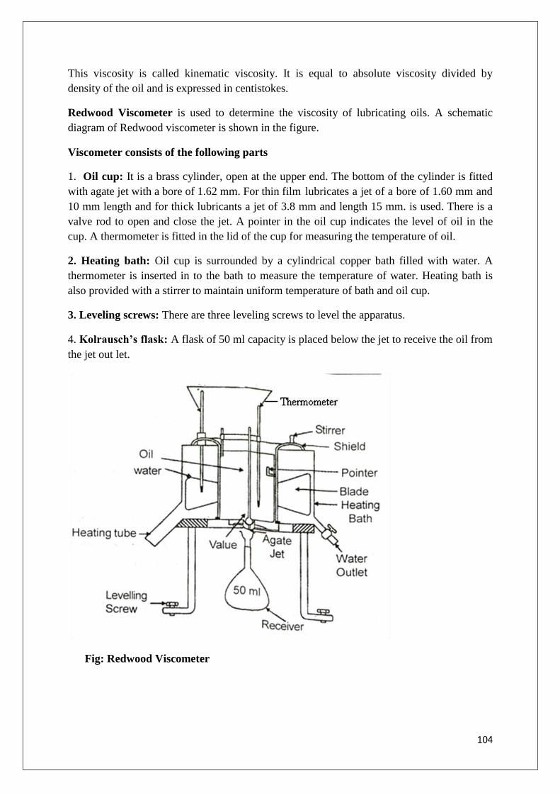
104
This viscosity is called kinematic viscosity. It is equal to absolute viscosity divided by
density of the oil and is expressed in centistokes.
Redwood Viscometer is used to determine the viscosity of lubricating oils. A schematic
diagram of Redwood viscometer is shown in the figure.
Viscometer consists of the following parts
1. Oil cup: It is a brass cylinder, open at the upper end. The bottom of the cylinder is fitted
with agate jet with a bore of 1.62 mm. For thin film lubricates a jet of a bore of 1.60 mm and
10 mm length and for thick lubricants a jet of 3.8 mm and length 15 mm. is used. There is a
valve rod to open and close the jet. A pointer in the oil cup indicates the level of oil in the
cup. A thermometer is fitted in the lid of the cup for measuring the temperature of oil.
2. Heating bath: Oil cup is surrounded by a cylindrical copper bath filled with water. A
thermometer is inserted in to the bath to measure the temperature of water. Heating bath is
also provided with a stirrer to maintain uniform temperature of bath and oil cup.
3. Leveling screws: There are three leveling screws to level the apparatus.
4. Kolrausch’s flask: A flask of 50 ml capacity is placed below the jet to receive the oil from
the jet out let.
Fig: Redwood Viscometer

105
Working:
The apparatus is leveled with leveling screws. Water bath is filled with water and a
thermometer is inserted into it. Oil cup is thoroughly cleaned and the jet is closed with ball
valve. The oil is filled in the cup upto the point, and a thermometer is inserted into the cup to
note the temperature of oil. Water bath is heated to a certain temperature with constant
stirring to maintain uniform temperature of water. When the oil acquires desired temperature,
heating is stopped and the ball valve in lifted. The time taken to fill the Kohlrausch flask of
50 ml capacity is noted. The valve is immediately closed to prevent the overflow of oil. The
experiment is repeated and the mean value of time of flow for 50 ml oil sample is reported
and the result is expressed in “Redwood No 1 seconds” at a particular temperature. Viscosity
of liquids decreases with increases in temperature. Agood lubricating oil should not undergo
change in viscosity with temperature.
Viscosity Index:
To indicate the change in viscosity with temp. an arbitrary scale, known as “viscosity
index” is used.
Viscosity index is a scale based on arbitrarily fixing a value of 100 for pennsylvanian
oils containing paraffin's.
The viscosity of paraffin oil (VH) is little affected by increasing temperature.
At lower end of scale viscosity index is fixed as „0‟ for Gulf coast oil (VL) which
contains naphthenes, whose viscosity decrease drastically with increasing
temperature.
A high value of viscosity index for an oil indicates that its viscosity is slightly
affected by increase in temperature and a low value of V.I. indicate that its viscosity
appreciably changes with temperature rise.
The mathematical expression for viscosity index (VI) is:
VI = L - U/L – H x100
Where, U = viscosity of test oil at 38oC
L = viscosity of the standard oil at 38oC having a VI of zero
H = viscosity of the standard oil at 38oC having a VI of 100
Flash Point and Fire Point
• Flash point is defined as the minimum temperature at which the lubricating oil gives off
its vapours that ignite for a moment, when a flame is brought near to it.
• Fire point is the lowest temperature at which the vapours of the oil burn continuously for
at least five seconds, when a flame is brought near to it.
• The flash point of the lubricating oil is above the operating temperature, because good
lubricating oil should not volatalize under the working conditions usually.
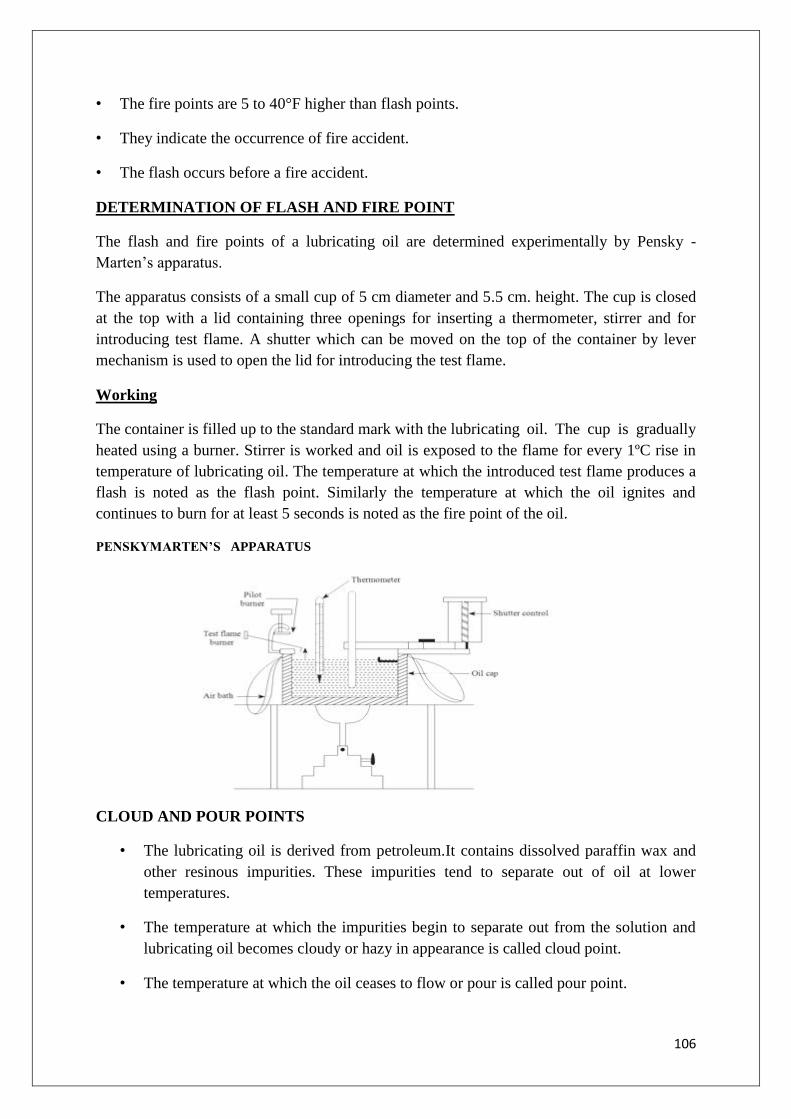
106
• The fire points are 5 to 40°F higher than flash points.
• They indicate the occurrence of fire accident.
• The flash occurs before a fire accident.
DETERMINATION OF FLASH AND FIRE POINT
The flash and fire points of a lubricating oil are determined experimentally by Pensky -
Marten‟s apparatus.
The apparatus consists of a small cup of 5 cm diameter and 5.5 cm. height. The cup is closed
at the top with a lid containing three openings for inserting a thermometer, stirrer and for
introducing test flame. A shutter which can be moved on the top of the container by lever
mechanism is used to open the lid for introducing the test flame.
Working
The container is filled up to the standard mark with the lubricating oil. The cup is gradually
heated using a burner. Stirrer is worked and oil is exposed to the flame for every 1ºC rise in
temperature of lubricating oil. The temperature at which the introduced test flame produces a
flash is noted as the flash point. Similarly the temperature at which the oil ignites and
continues to burn for at least 5 seconds is noted as the fire point of the oil.
PENSKYMARTEN’S APPARATUS
CLOUD AND POUR POINTS
• The lubricating oil is derived from petroleum.It contains dissolved paraffin wax and
other resinous impurities. These impurities tend to separate out of oil at lower
temperatures.
• The temperature at which the impurities begin to separate out from the solution and
lubricating oil becomes cloudy or hazy in appearance is called cloud point.
• The temperature at which the oil ceases to flow or pour is called pour point.

107
• Cloud point and pour points indicate the suitability of lubricants in cold conditions.
• Machines working with low temperatures like refrigerator plants, aircraft engines,
lubricants with low cloud and pour points are preferred
DETERMINATION OF CLOUD AND POUR POINTS
The cloud and pour points are determined experimentally using pour point apparatus.
The apparatus consists of flat bottomed glass tube filled with lubricating oil of standard
height enclosed in an air jacket. The jacket is surrounded by freezing mixture (ice + CaCl2).
A thermometer is introduced in the oil. As the cooling proceeds slowly, the temperature falls
continuously. For every 1ºC fall of temperature, the tube is withdrawn from air jacket for a
moment and observed for cloudiness.
The temperature at which cloudiness is noticed is recorded as cloud point. Similarly after
sometime the temperature at which the lubricating oil solidifies and resists to flow is recorded
as the pour point.
Fig: Pour point apparatus
REFRACTORIES
Refractories are inorganic materials which can withstand very high temperatures without
softening or suffering deformation. They are used for the construction of kilns ,oven ,
crucibles, retorts, furnaces, The main function of refractories varies depending on the
purpose to which they are subjected like confining heat within the furnace, transmitting or
storing heat in regenerators. The selection of a refractory for a particular purpose depends on
the service conditions, like working temperature to which it is exposed, the nature of the
materials which come into contact with it, temperature fluctuations, load applied and the
nature of chemical reactions which occur.

108
Classification of Refractories:
Refractories are broadly classified into three categories.
1.On the basis of their chemical nature
a) Acidic refractories: They are made from acidic materials such as alumina (Al2O3) and
silica (SiO2). They are resistant to acid slags, but attacked by basic materials such as
CaOMgO.
Examples: Silica, Alumina and (fireclay refractories contain silicate mineral kaolinite.
Silicate refractories which rank next to fireclay refractories are produced from quartzite and
quartz pebbles).
b) Basic refractories: Basic refractories are those which consist of basic materials. They
are not attacked by basic materials, but attacked by acidic materials
Examples: Magnetite, dolomite, chrome magnetite refractories.
c) Neutral refractories; they are not completely neutral in chemical since. They consists of
weakly basic/
Acidic materials such as carbon, zirconia (ZrO2), Chromite (FeOCrO2), graphite and silicon
carbide.
2. On the basis of fusion temperature:
a) Normal refractory: Fusion temperature is 1580-1780 C
Examples: fire clay refractory.
b) High refractory: Fusion temperature is 1780-2000 C
Examples: chromite refractory
c) Super refractory: Fusion temperature is above 2000 C
Examples: zirconia
3. On the basis of oxide content:
a) Single oxide refractory.
Examples: Alumina, magnesia and zirconia refractory.
b) Mixed oxide refractory.
Example: Spinel and mullite.
c) Non–oxide refractory.
Examples: Borides, carbides and silicates.
Characteristics of a Refractory:

109
A good refractory material should possess:
1. High temperature resistance under working conditions.
2. Good abrasion resistance by dusty gases and molten metals.
3. Low permeability or ability to contain heat.
4. High mechanical strength, structural strength and crack resistance to withstand overlying
load
5.Thermal strength to withstand thermal shock due to rapid and repeated temperature
fluctuations.
6. High resistance to change in physical, chemical and mechanical properties.
PROPERTIES OF REFRACTORIES:
Chemical inertness:The refractory materials used as lining for furnace should be chemically
inert. It should not react with slags, reagents, furnace gases, fuel ashes and products
produced inside the furnace. Acidic refractories should not in contact with alkaline product,
vice versa.
Examples: silica bricks being acidic cannot be used in a basic furnace and magnetite
bricks being basic cannot be used in acidic furnace.
Refractoriness:It indicates the ability of a refractory to bear its own weight at high
temperature. The refractory materials should not undergo deformation with increase in
temperature. Higher the softening temperature, more valuable is the refractory.
Refractoriness is expressed in pyrometric cone equivalents (PCE). The material whose
refractoriness is to be tested is taken in the form of cone and similar sized standard cone is
also taken. Then both the cones are heated uniformly at 100C per minute. The standard cones
possess definite softening temperature, standard cones are given the number 22 to 42 with
increasing softening temperature. When the test cone gets softened and loses its shape, one
of the standard cones whose refractoriness is close to that of the test cone will also
soften. The serial number of that standard cone is noted and this number is the PCE of test
cone. The softening temperature range of this pair is also noted. For example, silica bricks
has PCE of 33 with a softening temperature range of 1700-17500C.This indicates that
particular refractory can be used in the temperature range of 1700oC
.
Thermal expansion and contraction:The expansion and contraction of a good refractory
should be negligible with change in temperature. Repeated contractions and expansion of

110
refractory materials will lead to the breakdown of refractory materials. The lower the thermal
expansion and contraction, the better the quality of the refractory.
Porosity Combustible materials like sawdust when used as raw materials for making bricks
make them porous. Certain foaming agents are added to make the refractory porous. The
porosity of a refractory is the ratio of its pore volume to the total or bulk volume. Porosity
influences the strength of a refractory. If it is highly porous, molten reactants, gases, slags.
etc., penetrate and damage the brick. As a result, its abrasion resistance and mechanical
strength decrease. Contrary to it, in a porous brick the pores act as an insulator for the furnace
porosity decreases thermal spalling.
Thermal Spalling: The breaking, cracking, peeling of a refractory can be reduced by (1)
using materials with low porosity and low coefficient of expansion, (2) avoiding sudden
changes in temperatures and (3)Avoiding over firing during construction and finishing of
internal lining of refractories.
Refractoriness under load (RUL): Refractories used in metallurgical operations and
industries should withstand overlying load. They should have high mechanical strength at
operating temperature. Load – bearing capacity of a refractory is measured by RUL test. In
RUL test, a constant load (1.75Kg/cm2).is applied to a test material and heated at a rate of
10oC per minute in a furnace. The temperature at which at least 10% of specimen starts
getting deformed is taken as RUL value.
Examples: When appreciable load is applied, fire clay refractories collapses at a temperature
below fusion temperature. On the other hand, silica refractories withstand load even at high
temperature. RUL test is performed to know the safe upper temperature limit up to which the
refractory can be used.
Dimensional stability: It is defined as the resistance of material to any volume changes
which may occur because of its exposure to high temperature over a prolonged period of
time. These dimensional changes may be reversible or irreversible. Further the irreversible
changes may result in contraction or expansion, due to transformation of one crystalline form
into another.
For ex: a) Conversion of magnesite bricks into more dense periclase
b) Conversion of quartz in silica bricks to cristobalite.
Thermal conductivity: In many of the industrial operations, refractory materials of both
high thermal conductivity and low thermal conductivity are required depending upon the type
of furnace. The conductivity of a refractory primarily depends on its chemical composition
and porosity. As porosity increase, the thermal conductivity decreases because the entrapped
air in the pores function as insulator. In contrast dense refractories have high thermal
conductivity.

111
Most of the furnaces are lined inside with refractory materials of low thermal conductivity
in order to reduce heat losses to the outside environment by radiation. Refractories which can
be used under these circumstances are fire clay and silica, on the other hand in muffle
furnaces, construction of retorts, the heat should be efficiently transmitted and therefore
carbon and silicon carbide refractories which are poor insulators can be employed
Applications of Refractories
1.The main objective of a refractory is to resist heat losses and also to resist the abrasive and
corrosive action of molten metals, slags and gases at higher temperatures, without softening
or deformation in shape.
2. Refractories are mostly used for the construction of the lining of the furnaces, tanks,
converters, kilns crucibles, ladles, etc. They are employed for the manufacture of cement,
glass, ceramics, paper, metals (both ferrous and non-ferrous), etc.
Ex.Alumina bricks or fire clay refractories.
It is used in lining of cement rotary kilns soaking pita, reheating furnaces, hearts and
walls, etc., which are subjected to high abrasion.
It is used in hottest zone of cement rotary kilns, lower parts of soaking pits, brass
melting reverberatories, aluminium melting furnaces, etc.,
Ex. Fireclay refractories
They are used where high temperature is required to be maintained, together with
great resistance to basic materials.
They are used in steel industry for the lining of basic converters and open–hearth
furnaces.
They are also used in hot mixer linings, copper converters and reverberatory furnaces.
Ex. Zirconia bricks
They are used only where very high temperature is maintained, e.g., high – frequency
electric furnaces.
Nanomaterials
Introduction:
Nanomaterials are the materials of nano-metre (10-9
m) dimension.
The properties of nano materials significantly differ from bulk materials.
For e.g.: The electronic structure of metals and semi conductor crystals greatly differs
from those of isolated atoms and bulk materials.
Some of the nano materials like gold particles of 1-2nm size exhibit unusual catalytic
properties. Large pieces of gold and silver show inert (noble) behavior.
Silver is widely used in jewellery because of its inert nature, but it shows anti-
bacterial activity at nano scale.
Now-a-days nano particles of silver are used in wound dressing.

112
The uniqueness of nano particles is due to two factors.
Smaller particles have a relative large surface area than their volume,
Below 100nm size, quantum effects can change the magnetic and electronic
properties.
Nano particle reinforced polymeric materials could replace structural metallic
components in the automobile industry.
Wide spread use of the nano composites could reduce the consumption of 1.5 billion
liters of gasoline by the vehicles in 1 year thereby reducing CO2 emission by about 5
billion Kg annually.
Nanotechnology is the latest technology in which the materials are used in nano size, i.e.
atoms are in the order of 1 to 100nm.
Nanoscale: 1nm = 10-9
m = 10-7
cm
Nano means 10-9
m i.e. a billionth part of a meter. Atoms are extremely small & the diameter
of a single atom can vary from 0.1 to 0.5nm depending on the type of the element.
Ex: Carbon atom – 0.15 in diameter, water molecule – 0.3nm
Red blood cell – 7,000nm, Human hair-80,000nm wide
White blood cell-10,000nm, Virus – 100nm, Hydrogen atom-0.1nm
Bacteria range – 1,000 to 10,000nm, proteins – 5 to 50nm
DNA – 2nm Width, Quantum dots – 8nm
Nano particles – 1 to 100nm, Fullerenes – 1nm
Nano Materials: The materials in which the atoms are in the order of 1 to 100nm and these
atoms will not move away from each other, called as Nano materials.
Ex: C, ZnO, Cu – Fe alloys, Ni, Pd, Pt etc.
1. Materials that are nanoscale in one dimension called as nano layers [Thin
films, surface coatings].
2. Two dimensional nanomaterials are called as nano tubes and nano wires.
3. Three dimensional nano-materials are called as nano particles.
Ex: Precipitates, Colloids & quantum dots, tiny particles of semi-conductor
materials.
Classification of Nano-materials:
Generally, nano materials are categorized into two types. They are
1. Fullerenes
2. Inorganic nano particles

113
1) Fullerenes: The fullerenes are class of allotropes of carbon which are graphene sheets
rolled into tubes or hollow spheres. Fullerenes are again divided into two types
a) Bucky balls
b) Carbon nano-tubes or bucky tubes.
a) Buckyballs: Spherical fullerenes are called as buckyballs. The first fullerene
“buckminister fullenrene C60” was discovered by “Richard Buckminister Fuller”, a
famous arichetectural modeller in 1985.
b) Carbon nano tubes or bucky tubes:
Cylindrical fullerenes are called as carbon nano tubes or bucky tubes. Fullerenes are
similar to graphite structure, but they contain pentagonal rings.
Carbon nano tubes are of two types,
i) Single walled nano tubes ( SWNT )
ii) Multi Walled nano tubes ( MWNT )
3) Nano particles: Nano particles sized 1 & 100 nm are available in different forms such as
clusters, metal nano particles, Colloids, nano crystals, quantum dots etc.
Nano clusters have dimension between 1 & 100nm
Nano powders are agglomerates of nano particles (or) clusters.
Nano sized single crystals are called as nano crystals.
When nano particles are in suspended form in liquid phase, it is called as nano
colloids.
Quantum dots are tiny particles of semiconductor materials.
Nanomaterials exhibit different properties when compared to bulk materials. For example,
opaque substances become transparent(copper), inert materials become catalysts (Platinum),
Solids change into liquids at room temperature (gold), semiconductors become conductors
(silicon).
Basic principles /properties of Nanomaterials:
Two principal factors can cause the properties of nanomaterials to differ significantly from
bulk materials. They are
(i) Increase in surface area to volume ratio
(ii) Quantum confinement
Preparation of Nanomaterials:

114
SOL-GEL method: Sol-gel method one of the important methods for processing fine nano
particles with nano size distribution with controlled chemical composition at low
temperatures
The solution in which the molecules of nanometer are dispersed appear clear. The
colloids in which molecules of size ranging from 20 nm to 100 nm appear milky. A colloid
suspended in a liquid is called as Sol. A suspension that keeps its shape is called gel. This sol
gels are suspensions of colloids in liquids that keep their shape.
The materials used in the preparation of sol are metal alkoxides and alkoxy silanes. The most
widely used are tetramethoxysilanes (TMOS) and tetraethoxysilanes. Sol-gel formation
occurs in different stages.
Step1: Hydrolysis:
TEOS is a molecule which displays 4 functional arms (O-C2H5). During hydrolysis, addition
of water results in the replacement of (O-C2H5) group with OH group. Formation of different
stable solutions of alkoxide or solvated metal precursor (the sol)
(C2H5O)3-Si-OC2H5 + H2O (C2H5O)3-OH + C2H5OH
Step 2: Condensation:
Gelation resulting from the formation of an oxide or alcohol bridged network (the gel) by
polycondensation reaction.
(C2H5O)3-Si-OH + HO-Si-(OC2H5)3 (C2H5O)3–Si-O-Si-(OC2H5)3
The continuous formation of bridges (Si-O-Si bridges), induces the formation of a polymetric
tri-dimensional network. This results in dramatic increase in the viscosity of the solution.
Step 3: Growth and Agglomeration:
As the number of siloxane bonds increase, the molecules aggregate in the solution. Ageing of
the gel, during which the polycondensation reactions continue until the gel transforms into
solid mass. This is accompanied by contraction of the gel network and expulsion of solvent
from gel pores
Step 4: Drying of the gel when water and other volatile liquids are removed from the gel
network
Step 5: Dehydration, during which surface bound M-OH groups are removed. This is
normally achieved by calcination.
The typical steps that are involved in sol gel processing are shown by different process, one
can get either nanofilm coating or nanopores or dense ceramic with nanograins
Advantages of sol gel method:
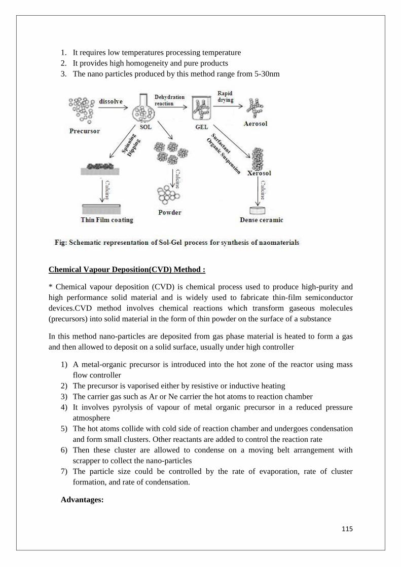
115
1. It requires low temperatures processing temperature
2. It provides high homogeneity and pure products
3. The nano particles produced by this method range from 5-30nm
Chemical Vapour Deposition(CVD) Method :
* Chemical vapour deposition (CVD) is chemical process used to produce high-purity and
high performance solid material and is widely used to fabricate thin-film semiconductor
devices.CVD method involves chemical reactions which transform gaseous molecules
(precursors) into solid material in the form of thin powder on the surface of a substance
In this method nano-particles are deposited from gas phase material is heated to form a gas
and then allowed to deposit on a solid surface, usually under high controller
1) A metal-organic precursor is introduced into the hot zone of the reactor using mass
flow controller
2) The precursor is vaporised either by resistive or inductive heating
3) The carrier gas such as Ar or Ne carrier the hot atoms to reaction chamber
4) It involves pyrolysis of vapour of metal organic precursor in a reduced pressure
atmosphere
5) The hot atoms collide with cold side of reaction chamber and undergoes condensation
and form small clusters. Other reactants are added to control the reaction rate
6) Then these cluster are allowed to condense on a moving belt arrangement with
scrapper to collect the nano-particles
7) The particle size could be controlled by the rate of evaporation, rate of cluster
formation, and rate of condensation.
Advantages:

116
1) Increased yield of nanoparticles
2) A wide range of ceramics including nitrides and carbides can be synthesised
3) More complex oxides such as BaTiO3 can be formed
4) In addition to the formation of single phase nanoparticles by a single precursor, doped
nanoparticles and coated nanoparticles are synthesised by supplying two precursors
Fig: Chemical Vapour Deposition Method
Applications of Nanomaterials:
Nano chemistry undertakes the synthesis of precisely defined nano particles to achieve novel
materials for specific applications in the field of medicine, advanced catalysis, control
pollution, storage devices, optical and electronic devices.
In Electronic Devices:
(1) The potential application of nano particles is in the design of new super computers,
includes zero dimensional quantum dots, one dimensional quantum dot, nano scale
circuits etc.
(2) In communication technology, nanowires 20times thinner and longer than
conventional wires are used
In Solar Cells:
Nanotechnology improves energy efficiency, storage and production of solar cells.
Solar cells are expensive and nano-meter sized solar cells provide more energy at a
cheaper price.
This would reduce the usage of fossil and nuclear fuels.
In Food:
Silver nanoparticles embedded in plastic for storage bins to kill bacteria, minimizing health
risks from harmful bacterial
Clay nanoparticles used in bottles, cartons and films to act as barrier to the passage of gasses
and odours

117
A combination of nanomaterials with enzymes improves the durability of enzymes, creates
localized high concentration of proteins and reduces cost by minimizing losses.
In Automobiles:
Nylon nanocomposites containing small amount of clay are capable of withstanding high
temperature environments and used in automobile air intake covers.
High power switches in ignition devices
On-line sensors for the measurement of wear and abrasion
Create more efficient ultra-thin hydrocarbon membranes which allow to build light-weight
fuel cells
To Control Pollution:
Nanotechnology helps in reducing chemical pollution.
Nanoparticles as catalysts to transform vapours escaping from cars or industrial plants
into harmless gases
Nanostructures menbranes to separate CO2 from industrial plant exhaust streams
Eg. TiO2 nanocrystals for air purification, manganeseoxide nanoparticles containing
catalysts for removal of volatile organic compounds in indudtrial air emissions.
Water Pollution
Nanotechnology helps in reducing water pollution
Iron nanoparticles convert the contaminating chemicals to harmless compound
Usage of electrodes composed of nano-sized filters to remove salts or metals
Usage of filters of few nanometer in diameter to remove virus cells from water. Eg.nanofibres
As Catalyst:
Catalyst are stable at high temperatures and can be used in smaller possible amount
have been discovered.
Eg: Rhodium hydrosols are the effective catalysts for the hydrogenation of olefins in
organic phase.
The complex oxide barium hexaaluminate BaO3 Al2O3 retains its catalytic activity at
high temperature.
Nano chemical routes catalyze the chemical reactions at much lower temperature,
pressure and in a very short period of time.

118
In Medical field:
In the field of medicine and surgery nano technology possesses several potential
applications
Mutations in DNA could be repaired and cancer cells, toxic chemicals, viruses could
be destroyed with the help of nano devices.
Sensor systems which detect the emerging diseases in the body would shift the focus
from the treatment of disease to early detection and prevention.
eg: Nano scale devices smaller than 50nm can easily enter most cells and those
smaller than 20nm can move through the walls of the blood vessels. As a result, a
nano-scale device can interact with molecules on both the cell surface and within the
cell.
Eg. Nanocrystalline silver as antimicrobial agent in the treatment of wounds
Biomarkers to disease identification, for targeteddelivery of drugs to tumors
Nanoparticles that target tumor cells such as iron and gold
Aluminosilicate nanoparticles in medical gauze which help blood clot fater in open
wounds
Consumer products
Increasing the strength of tennis rackets by adding nanotubes to the frame which
increases control and power
Using nao-sized material to fill any voids in golf shafts
Cleaning products:
TiO2 nanoparticles spary on film that uses energy fromlight to kill bacteria onn
surfaces
Silver manoparticles used in household appliances such as refrigerator or washing
machines for cloths to kill bacteria and reduce odour.
In Space
Nanotechnology helps in creating lighter, stronger and thermally stable materials for aircrafts,
rockets and exploratory platforms
Employing materials made from CNTs to reduce the weight of space ships while even
increasing the structural strength.
In Defence
Nanotechnology has tremendous potential in defence applications. Nanosensors are used in
aircrafts for vibration damping, noise reduction and life monitoring of missiles

119
Fullerenes:
Fullerenes, carbon nano materials were under study for potential medicinal use.
Fullerenes are classes of allotropes of carbon which conceptually are graphene sheets
rolled into tubes or spheres.
Fullerenes are the classic three-dimensional carbon nano materials.
This is made of 60 carbon atoms arranged in a soccer ball like shape and is less than
1nm in diameter.
It has a hollow interior. There are now thirty or more forms of fullerenes up to and
beyond C120. The important fact for nanotechnology is that atoms can be placed inside
the fullerene.
Eg: The hollow structure can fit a molecule of a particular drug inside, while outside
buckyball is resistant to interaction with other molecules in the body.
So, they can be safe functional drug „containers‟ that can enter cancer cells without
reacting with them.
Buckminster fullerene C60, also known as buckyball, the smallest member of the fullerene
family.
Buckminster fullerene was prepared in 1985 by Richard Smalley, Robert Curl, James
Health, Sean O‟ Brien and Harold Kroto.
This is a football like structure made of carbon atoms.
It contains 12 pentagons and 20 hexagon rings joined together to produce C60.
It contains 60 carbon atoms in 32 rings.It is hollow inside.The average bond length is
1.4A0.
Medicinal use of fullerenes are binding specific antibiotics to the structure of resistant
bacteria and even certain types of cancer cells such as melanoma.
A common method used to produce fullerenes is to send a large current between two
nearby graphite electrodes in an inert atmosphere.
The resulting carbon plasma are between the electrodes cools into sooty residue from
which many fullerenes can be isolated.
The applications include catalysts, drug delivery systems, optical devices, chemical
sensors and chemical separation devices.
The molecule can absorb hydrogen with enhanced absorption when transition metals
are bound to the fullerenes, leading to potential use in hydrogen storage.
To replace steel in suspension bridges.
To produce nano wires of gold and zinc oxide
To replace indium-tin oxide in LCDs, touch screens
As artificial muscles
To be used in cancer therapy.
These are some other applications of fullerenes.

120
Fig: Fullerene/buckyball
Quantum Dots:
Quantum dots are referred as artificial atoms.
Quantum dot is a semiconductor that exhibits quantum confinement properties in all
three dimensions.
The size is in the range of 1-10nm.
E.g.: cadmium selenide, lead selenide etc.
They display any chosen colour in UV-region.
Because of this property multi colour lasers are developed.
Quantum dots absorb photons from solar radiation and release electrons to generate
electricity.
Used to manufacture extremely efficient thin-film photo voltaic cells
Used in transistors, LEDs and diode layers as agents for medical imaging.
In communication technology, nano wires 20-times thinner and longer than
conventional wires are used.
The magnetic nano metal particles are widely used in magnetic separation, magnetic
drug transport and magneto-optical data storage.

121
UNIT III - Water
Introduction
For the existence of all living beings (humans, animals and plants) water is very crucial.
Without water we cannot survive and almost all human activities–domestic,agricultural and
industrial demand use of water. Although water is nature‟s most wonderful and abundant
compound but only less than1% of the world‟s water resources are available for the ready
use. As engineering material water is used for producing steam in boilers to generate
hydroelectric power, furnishing steam for engines,for refrigeration and air conditioning, for
construction of concrete structures for manufacturing purposes and as a solvent in the
chemical process
Hardness
Hardness of water is defined as the property which prevents the lathering of soap. This is due
to presence of certain salts of Ca+2
, Mg+2
and other heavy metals dissolved in it. Soaps are
sodium or potassium salts of higher fatty acids like oleic acid or palmitic acid or stearic acids
(C17H35COONa).Hard water does not give lather with soap while soft water gives lather
readily with soap.
Soap with hard water reactions
When soap comes in contact with soft water lather is produced due to sodium stearate.
C17H35COONa+H2O → C17H35COOH +NaOH
(Sodium stearate) (Stearic acid)
When soap comes in contact with hard water, sodium stearate will react with dissolved
calcium and magnesium salts and produce calcium stearate or magnesium stearate which is
white precipitate. This insoluble white precipitate prevents lathering of soap.
2C17H35COONa+CaCl2→ (C17H35COO)2Ca+2NaCl
(Sodium stearate) (insoluble scum)
2C17H35COONa+MgSO4 → (C17H35COO)2Mg+Na2SO4
(Sodium stearate) (insolublescum)
Different types of water have different degrees of hardness.The different types of water are
commercially classified on the basis of degree of hardness as follows:
Hardness Name of water
0-70mg/liter Soft water
70-150mg/liter Moderate hard water
150-300mg/liter Hard water
300mg/liter Very hard water
Degree of hardness:

122
The total hardness of water is caused by eight different dissolved salts of calcium and
magnesium,[Ca(HCO3)2,Mg(HCO3)2, CaCl2,MgCl2,CaSO4,MgSO4,Ca(NO3)2and Mg(NO3)2].
Hence the hardness of water is expressed in terms of calcium carbonate equivalents. The
weight of different hardness salts causing hardness are converted to weight equivalent to that
of calcium carbonate. CaCO3 is selected for expression of hardness because the molecular
weight of CaCO3 is 100,which is easy for calculation and it is the most insoluble salt and all
the dissolved salts of calcium are precipitated as CaCO3.
Name of the salt Molecular weight
Ca(HCO3)2 162
Mg(HCO3)2 146
CaCl2 111
MgCl2 95
CaSO4 136
MgSo4 120
CaCO3 100
The method for calculating degree of hardness will be clear from the following formula:
Hardness of water in terms of calcium carbonate equivalents
Amount of hardness causing salts
= × 100
Molecular weight of hardness causing salts
Causes of hardness
The natural water is usually contaminated by different types of impurities.
They are mainly 3 types
1. Physical impurities
2. Chemical impurities
3. Biological impurities
Expression of hardness – Units
Units of Hardness:
1Parts Per Million: Parts of CaCO3 equivalent hardness per 106parts of water.
1 ppm = 1 part of CaCO3 equivalent hardness present in 106parts of water.
Milligram per liter: Number of milligrams of calcium carbonate equivalent hardness
present in 1 liter of water.
1mg / L = 1 mg of CaCO3 equivalent hardness present in 1 liter of water.
1 L = 1 Kg = 1000 g = 1000 x 1000 mg = 106 mg.
1mg /L= 1 mg of CaCO3eq per 106 mg of H2O = 1ppm

123
Degree Clark: (°Cl):It is the number of grains (1/7000 lb) of CaCO3 equivalent
hardnessper 70,000 parts of water.
1Clark = 1 grain of CaCO3 equivalent hardness per gallon of water.
= 1 part of CaCO3 of hardness per 70,000 parts of water.
Degree French (°Fr): It is the parts of CaCO3 equivalent hardness per 105 parts of water.
10French =1 part of CaCO3per 10
5parts of hard water
Milliequivalents per litre : - No of milliequivalentsof hardness present per liter of
water.
1m eq/L= 1 m eq of CaCO3 per / liter of water.
= 50 mg /L of CaCO3eq = 50ppm
Relation between various units of hardness:
Types of Hardness
Hardness of water is mainly two types
1. Temporary Hardness
2. Permanent Hardness
1.TemporaryHardnessmainly caused by the presence of dissolved bicarbonates of
calcium, magnesium and other heavy metals.
The salts mainly responsible for temporary hardness of water are
1. Calcium bicarbonate Ca(HCO3)22. Magnesium bicarbonate Mg(HCO3)2
When bicarbonates are decomposed, yielding insoluble carbonates or hydroxides,which gets
deposited as a crust at the bottom of vessel.Temporary hardness can be largely removed by
mere boiling of water.On boiling bicarbonates converts into corresponding carbonates which
are insoluble. They can be removed by filtration.
Ca(HCO3)2→CaCO3+H2O+CO2
(Calcium bicarbonate)
Mg(HCO3)2→Mg(OH)2+2CO2
(Magnesium bicarbonate)
2. Permanent Hardness: It is due to the presence of dissolved chlorides and sulphates of
calcium, magnesium, iron and other metals.The salts responsible for permanent hardness are
CaCl2, MgCl2, CaSO4, MgSO4, FeSO4, Al2(SO4)3. Permanent hardness cannot be removed by
boiling but it can be removed by the use of chemical agents.
1 ppm = 1mg /L = 0.10Fr = 0.07
0Cl = 0.02 meq /L

124
Estimation of temporary & permanent hardness of water
Estimation of Hardeness of Waterby EDTA method(Complexometric titration)
This is a complexometric titration where ethylene diamine tetra acetic acid [EDTA] isused as
a complexing agent. EDTA form complexes with different metal ions at different PH9-10.To
maintain the PH
9-10 ammonical buffer is used. An alcoholic solution of Eriochrome black –T
is used as an indicator.The disodium salt of EDTA is used for complexation since solubility
of EDTA is very low.
Structure of EDTA:
Principle: In this complexometric titration, the water sample is titrated with standard
solution of Di-sodium salt of EDTA using EBT indicator. First EDTA solution is
standardized with a standard solution of calciumcarbonate, prepared by dissolving a known
weight of cacium carbonate in dil.HCl and then making up the solution to a known volume
with distilled water .The permanent hardness of water can be determined by titrating the
water after boiling well to remove the temporary hardness as carbonates of calcium and
magnesium against EDTA by adding EBT and buffer solution.Temporary hardness can be
determined by subtracting total hardness of water from permanent hardness of water.
Reactions involved: EBT indicator when added to hard water at pH = 10, forms weak
complexes with calcium and magnesium present in hard water. It results in the formation of
unstable wine red Ca-EBT or Mg-EBT complexes. During titration with EDTA, calcium first
reacts to form relatively stable complex followed by magnesium to give Mg+2
-EDTA
complex releasing the free indicator(blue).The colour changes from wine-red to blue at the
endpoint.

125
Various steps involved in this method are…
1. Preparation of standard hard water: Dissolve 1g of pure, dry CaCO3 in minimum
quantity of dil.HCl and then evaporate the solution to dryness on a water bath. Dissolve the
residue in distilled water to make 1 liter solution. Each mL of this solution thus contains 1mg
of CaCO3 equivalent hardness.
1 mL hard water solution = 1mg of CaCO3 equivalent hardness.
2. Standardization of EDTA solution: Rinse and fill the burette with EDTA solution.
Pipette out 50mL of standard hard water in a conical flask. Add 10-15mL of buffer solution
and 4 to5 drops indicator. Titrate with EDTA solution till wine-red colour changes to clear
blue.
3.Titration of unknown hard water:
Rinse and fill the burette with EDTA solution. Pipette out 50 ml of unknown sample hard
water in a conical flask. Add 10-15mL of buffer solution and 4 to 5 drops of indicator. Titrate
with EDTA solution till wine-red colour changes to clear blue. Let volume used be V1mL.
4. Titration of Permanent hardness: Take 250mL of the water sample in a large
beaker. Boil it till the volume is reduced to about 50mL, filter it, wash the precipitate with
distilled water, collect filtrate and washing in a 250mL measuring flask. Finally make up the
volume to 250mL with distilled water. Then, titrate 50mL of boiled water sample just as in
Step (2). Let volume used be V2mL.
Experimental Procedure:
To a knownvolume of the sample of hard water (Vml) 10ml of a buffer solution and 5 drops
of Eriochrome –Black T indicator are added.This solution is then titrated against the standard
EDTA solution. The end point is the colour change from wine-red to blue.
Let the volume of EDTA consumed =V1ml
1ml of EDTA=1mg of CaCO3
V1 ml of EDTA=V1mg of CaCO3
This hardness is present in V1ml of hard water
Total hardness of the sample=V1x1000ppm of CaCO3
V
A known volume of (Vml) of sample water is taken in a beaker and boiled for 15
minutes.After cooling it is filtered and the filtrate is collected and make upto a known volume
(Vml).This solution is titrated against EDTA. Hence the volume of EDTA consumed is V2ml.
Permanent hardness of the sample = V2x1000 ppm of CaCO3 equivalents
V
Hence temporary hardness= (Total hardness- Permanent hardness)
Hardness-Numerical Problems:
1) One liter of water from an underground reservoir in Nalgonda town in Andhra Pradesh
found to have the fallowing dissolved salts.Mg(HCO3)2=14.6mg, NaCl=11.7mg.

126
MgCl2=48mg, CaSO4=13.6mg, Ca(HCo3)2=32.4mg. Find the total hardness
temporary&permanent hardness of water in degree French.
Solution:
S.No Salt Amount (mg) Multiplication
factor
CaCO3
equivalents
1 Mg(HCO3)2 14.6 100/146 14.6x100/146
=10
2 NaCl 11.7 ------ -----------------
3 MgCl2 48 100/95 48x100/95 =50
4 CaSO4 13.6 100/136 13.6x100/136
=10
5 Ca(HCO3)2 32.4 100/162 32.4x100/162
=20
Temporary hardness = Mg(HCO3)2+ Ca(HCO3)2
= 10 + 20 = 30 ppm
Permanent hardness = CaSO4 + MgCl2
= 10 + 50 = 60 ppm
Total Hardness = Temporary hardness + Permanent hardness = 30 + 60 = 90 ppm
In degree French= 90×0.07=6.3oFr
2) One liter of water from Khammam Dist. in Andhra Pradesh showed the following
analysis: Mg(HCO3)2 = 0.0256gms, Ca(HCO3)2= 0.0156gms, NaCl = 0.0167gms, CaSO4
= 0.0065gms, and MgSO4 = 0.0054gms. Calculate temporary, permanent and total
hardness.
Solution:
S.No Salt Amount (mgs) Multiplication
factor
CaCO3 equivalents
1 Mg(HCO3)2 25.6 100/146 25.6x100/146=17.5
2 Ca(HCO3)2 15.6 100/162 15.6x100/162 =9.6
3 NaCl 16.7 ------------- --------------
4 CaSO4 6.5 100/136 6.5x100/136 =4.77
5 MgSO4 5.4 100/120 5.4x100/120 =4.5
Temporary hardness = Mg (HCO3)2 + Ca (HCO3)2
= 17.5 + 9.6 = 27.1ppm
Permanent hardness = CaSO4+ MgSO4
= 4.77 + 4.5 = 9.27ppm
Total Hardness = Temporary hardness + Permanent hardness
= 27.1 + 9.27 =36.37ppm
127
Boiler Troubles:
Water finds a great use in various industries for generation of steam in boilers. When water is
continuously evaporated to generate steam, the concentration of the dissolved salts increase
progressively causing bad effects for steam boilers. The boiler troubles that arise are
1. Carryover – Priming and Foaming
2. Scale formation
3. Boiler corrosion and
4. Caustic embrittlement
Carryover - priming & foaming
Priming: It may be defined as the violent or rapid boiling of water occurring in the boiler
which results in carrying out of water with steam in the form of a spray. When a boiler is
producing steam rapidly, some particles of liquid water are carried along with the steam. The
steam carrying water droplets is called wet steam.This process of wet steam formation is
called priming.
Reasons:
(i) Priming is mainly due to very high water level.
(ii) Presence of large amount of dissolved solids, high steam velocities, sudden increase in
steam production rate.
(iii)Sudden steam demand which leads to sudden boiling, presence of excessive foam filling
the foam spare, and due to faulty boiler design.
Priming can be controlled by
1. Proper boiler design,
2. Fitting mechanical steam purifier
3. Avoiding rapid change in steam-rate.
4. Proper evaporation and adequate heating surfaces,
5. Uniform distribution of fuel and providing anti priming pipes, keeping the water level
low and avoid sudden steam demands.
Foaming: Foaming is the formation of small but stable bubbles above the surface of water.
Reasons:
(i) The main reason for foaming is being presence of fatty acids and other impurities.
(ii)The presence of large quantity of suspended impurities and the oils lowers the surface
tension of boiler water producing foam.
Foaming can be controlled by
1. Using anti-foaming chemicals like castor oil. The amount of castor oil to be added
varies with the boiler.Excess of castor oil can cause foaming.
2. Removal of concentrated boiler water and replacing it by fresh feed water.
3. Removing oil from boiler water by adding compounds like sodium aluminate.
Disadvantages of priming and foaming:
Priming and foaming may cause the following boiler troubles:
1)The actual height of the water in boiler cannot be judged.

128
2) Wastage of heat with the result that it becomes difficult to keep up steam pressure and
efficiency of the boiler is lowered.
3)Water concentrated with dissolved salts may deposit on parts of the machinery, which
cause corrosion due to the formation of concentration cell in that part resulting the decay
of metal on that spot.
Scale and Sludge formation in boilers:
In boilers, because of continuous evaporation of water, the concentration of salts increases
progressively and after the saturation point is reached,salts are thrown out as precipitate on
the inner walls of boiler.
The precipitation can be takes place in two ways
i) Sludge ii)Scale
Sludge: Sludge is a soft, loose and slimy precipitate formed within the boiler. It is formed at
comparatively colder portions of the boiler and collects in the area where flow rate is slow.
Eg.MgCO3, MgCl2, CaCl2, MgSO4.
Dis-advantages:
a. As the sludges are poor conductor of heat they cause loss of heat.
b. The working of the boiler is disturbed because of chocking of pipes by the sludge.
Prevention:
a. By using well softened water.
b. By blow down operation i.e. by drawing off a portion of concentrated water frequently.
Scales: Scales are hard, adhering precipitates formed on the inner walls of the boilers. They
stick very firmly on to the inner wall surface.
Sludges and Scales in boilers
Causes of scale formation:
Following are the causes:
a. Decomposition of calcium bicarbonate:
Ca(HCO3)2→CaCO3 + H2O + CO2

129
In low pressure boilers, CaCO3causes scale formation.
In high pressure boilers, CaCO3becomes soluble.
CaCO3 +H2O →Ca(OH)2 + CO2
b. Decomposition of calcium sulphate:
The solubility of CaSO4in water decreases with rise of temperature. In super heated water
CaSO4 is insoluble. This is the main cause in high-pressure boilers.
c. Hydrolysis of Magnesium salts:
Dissolved Magnesium salts undergo hydrolysis forming Mg(OH)2precipitate causing scales.
MgCl2 + 2H2O →Mg(OH)2 + 2HCl
d. Presence of Silica: Silica present in small quantities deposits as silicates like CaSiO3 and
MgSiO3. These are very difficult to remove.
Disadvantages:
a. Wastage of fuel: The scale formation causes decreases of heat transfer. As a result over
heating is required this causes consumption of fuel.
b.Lowering of boiler safety: The hot scale cracks because of expansion and water suddenly
comes in contact with overheatediron plates. This causes in formation of large amount of
steam suddenly. This results in high pressure, causing boiler to burst.
c.Decrease in efficiency: Deposition of scales in the valves and condensers of the boiler,
choke them partially. This results in decrease in efficiency of boiler.
Removal of scales:
1. Scales can be removed by applying thermal shocks
2. Using scrapers, wire brush etc. scales can be removed.
3. Using certain chemicals scales can be removed.For example using 5-10% HCl.
Calcium carbonate scales can be removed. Calcium sulphate scales can be removed
using EDTA solution.
4. By blow down operation the scale formation can be avoided.
Prevention of scales or softening of hard water:
a. External treatment: Efficient softening of water is to be carried out by
i) Lime-soda process (ii) Zeolite process (iii) ion-exchange process
b. Internal treatment: Suitable chemicals are added to the boiler water either to precipitate
or to convert the scale into sludge.
1. Colloidal conditioning
2. Phosphate conditioning
3. Carbonate conditioning
4. Aluminates conditioning
5. Calgon conditioning
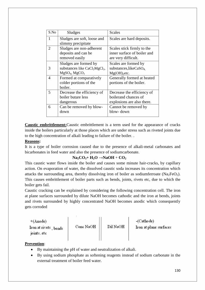
130
S.No Sludges Scales
1 Sludges are soft, loose and
slimmy precipitate
Scales are hard deposits.
2
Sludges are non-adherent
deposits and can be
removed easily
Scales stick firmly to the
inner surface of boiler and
are very difficult.
3
Sludges are formed by
substances like CaCl2MgCl2,
MgSO4, MgCO3
Scales are formed by
substances,likeCaSO4,
Mg(OH)2etc.
4
Formed at comparatively
colder portions of the
boiler.
Generally formed at heated
portions of the boiler.
5
Decrease the efficiency of
boiler butare less
dangerous
Decrease the efficiency of
boilerand chances of
explosions are also there.
6 Can be removed by blow-
down
Cannot be removed by
blow- down
Caustic embrittlement:Caustic embrittlement is a term used for the appearance of cracks
inside the boilers particularly at those places which are under stress such as riveted joints due
to the high concentration of alkali leading to failure of the boiler. .
Reasons:
It is a type of boiler corrosion caused due to the presence of alkali-metal carbonates and
bicarbonates in feed water and also the presence of sodiumcarbonate.
Na2CO3+ H2O →NaOH + CO2
This caustic water flows inside the boiler and causes some minute hair-cracks, by capillary
action. On evaporation of water, the dissolved caustic soda increases its concentration which
attacks the surrounding area, thereby dissolving iron of boiler as sodiumferroate (Na2FeO2).
This causes embrittlement of boiler parts such as bends, joints, rivets etc, due to which the
boiler gets fail.
Caustic cracking can be explained by considering the following concentration cell. The iron
at plane surfaces surrounded by dilute NaOH becomes cathodic and the iron at bends, joints
and rivets surrounded by highly concentrated NaOH becomes anodic which consequently
gets corroded
Prevention:
By maintaining the pH of water and neutralization of alkali.
By using sodium phosphate as softening reagents instead of sodium carbonate in the
external treatment of boiler feed water.

131
Caustic embrittlement can also be prevented by adding tannin or lignin or
Sodiumsulphate which prevents the infiltration of caustic-soda solution blocking the
hair-cracks.
Boiler Corrosion: The chemical or electro chemical eating away of metal by its environment
in a boiler is known as boiler corrosion. The main reason for this problem is the presence of
excess of oxygen in water. It can be prevented by mechanical deaerator, pre-heating and
chemical treatment.The main reasons for boiler corrosion are
(i) Dissolved oxygen
(ii) Dissolved carbondioxide
(iii)Acids produced by hydrolysis
a. Dissolved oxygen: Water usually contains about 8 ml of dissolved oxygen per liter at room
temperature. Dissolved oxygen in water, in presence of prevailing high temperature, attacks
boiler material:
2Fe + 2H2O + O2 →2Fe(OH)2
4Fe(OH)2 + O2→2[ Fe2O3.2H2O]
Removal of dissolved oxygen: By adding calculated quantity of sodium sulphite or hydrazine
or sodium sulphide.
2Na2SO3+ O2→2Na2SO4
N 2H4+O2→N2 + 2H2O
Na2S + O2→Na2SO4
Hydrazine is an ideal internal treatment chemical for the removal of dissolved oxygen. It
reacts with oxygen, forming nitrogen and water.
Mechanical De-aeration method: Dissolved oxygen can be removed from the water by
mechanical de-aeration .In this process water is allowed to fall slowly by the perforated plates
fitted inside the tower .The sides of the tower are heated and vacuum pump is also attached to
it.The high temperature and low pressure produced inside the tower considerably reduce the
oxygen content of the water.

132
b. Dissolved carbondioxide: Dissolvedcarbondioxide in water formscarbonic acid which is
corrosive in nature.
CO2 + H2O →H 2CO3
This has a slow corrosive effect on the boiler material. Carbon dioxide is also released inside
the boiler, if water used for steam generation contains bicarbonate,
Mg(HCO3)2→MgCO3 + H2O + CO2
Removal of carbondioxide:
1) By adding calculated quantity of ammonium hydroxide
2NH 4OH + CO2→(NH4)2CO3 + H2O
2) By mechanical–deaeration process:Same process is employed as in the case of
removal of oxygen.
c. Acids from dissolved salts: Water containing dissolved magnesium salts liberates acids on
hydrolysis.
MgCl2 + 2H2O →Mg (OH) 2 + 2HCl
The liberated acid reacts with iron in chain – like reactions producing HCl again and again.
Fe + 2HCl →FeCl2+ H2
FeCl2 + 2H2O →Fe (OH) 2 + 2HCl
Fe (OH2) + H2O+1/2O2→Fe2O3.3H2O (rust)
Prevention of acid corrosion:
(1)Softening of boiler water to remove MgCl2 from the water.
(2)By frequent blow down operation.
Treatment of water:
Internal treatment:
Internal treatment of boiler water is carried out by adding proper chemicals to precipitate the
scale forming impurities in the form of sludge and to convert the scale forming chemicals
into compounds which will stay in dissolved form in water.
1. Colloidal conditioning
2. Phosphate conditioning
3. Carbonate conditioning
4. Aluminates conditioning
5. Calgon conditioning
Colloidal conditioning: The addition of organic substances such as kerosene, tannin, gel etc.,
to the surface in low pressure boilers may prevent the scale formation. These substances gets
coated over the scale forming precipitates and gives a loose and non-sticky precipitates which
can be removed by blow-down operation.
Phosphate conditioning: The addition of sodium phosphate in hard water reacts with the
hardness causing agents and gives calcium and magnesium phosphates which are soft and
non-adhere and can be removed easily by blow-down operation. In this way, scale formation
is removed in high-pressure boilers.

133
3CaCl2 + 2 Na3PO4→Ca3(PO4)2 + 6NaCl
3MgCl2 +2Na3PO4→ Mg3(PO4)2 +6NaCl
The calcium phosphate and magnesium phosphate complexes were removed by blow down
operation.
The three phosphates employed for conditioning are
1. NaH2PO4 –sodium dihydrogen phosphate (acidic)
2. Na2HPO4–Di sodium hydrogen phosphate (weakly alkaline)
3. Na3PO4-Trisodium phosphate (alkaline)
Trisodium phosphate is the most preferred reagent because it not only form complex with
Ca+2
and Mg+2
ions,but also maintains the pH of water between 9-10,where the calcium and
magnesium ions undergo complexation.
Calgon conditioning: Involves in adding calgon to boiler water. It prevents the scale and
sludge formation by forming soluble complex compound with CaSO4.
Calgon = Sodium hexametaphosphate = Na 2 [Na4 (PO3)6]
Na 2[Na4 (PO 3)6] 2Na+ + [Na4 (PO3)6]
2CaSO4+ [Na4 (PO3)6] →[Ca2(PO3)6 ]-2
+ 2Na2SO4
Sodiumaluminate conditioning: Sodium aluminate gets hydrolyzed yielding NaOH and a
gelatinous precipitate of aluminum hydroxide.
Thus NaAlO2+ 2H2O → NaOH + Al (OH)3
The sodium hydroxide, so-formed, precipitates some of the magnesium as Mg (OH)2, i.e.,
MgCl2 + 2NaOH →Mg (OH)2 + 2NaCl
The flocculent precipitate of Mg(OH)2plus aluminum hydroxide, produced inside the boiler,
entraps finely suspended and colloidal impurities, including oil drops and silica. The loose
precipitate can be removed by predetermined blow-down operation.
Carbonate conditioning:
In low-pressure boilers, scale-formation can be avoided by adding sodium carbonate to
boiler water, where CaSO4 is converted into calcium carbonate.
CaSO4 + Na 2SO4→ CaCO3 + Na2 SO4
Consequently, deposition of CaSO4as scale doesn‟t take place and calcium is precipitated as
loose sludge of CaCO3 which can be removed by blow-down operation.
External treatment: The treatment given to water forthe removal of hardness causing salts
before it is taken into the boiler is called external treatment or softening of water. In industry
three main external treatment methods employed for softening of water are.

134
1. Lime-Soda process
2. Zeolite process
3. Ion-Exchange process
Lime-soda process: In this method, the soluble calcium and magnesium salts in water are
chemically converted in to insoluble compounds, by adding calculated amount of lime and
soda. CaCO3and Mg(OH)2 so precipitated, these precipitates are filtered off.
Lime → It removes temporary hardness due to Ca(HCO3)2, Mg(HCO3)2,and permanent hardness
due to MgCl2,MgSO4. It also removes dissolved gases like CO2, and acids HCl,H2SO4, and
bicarbonates and alums
Soda→Itremoves permanent hardness due to CaSO4, CaCl2, MgCl2 and MgSO4
Lime soda process mainly two types, they are
1. Cold Lime-soda process
2. Hot Lime-soda process
Calculation of Lime and Soda required for the process
Dissolved salt Chemical reaction Treatment
required
Ca(HCO3) Ca(HCO3)+Ca(OH)2 → 2CaCO3+2H2O
Lime
Mg(HCO3)2 Mg(HCO3)2+2Ca(OH)2→Mg(OH)2+2CaCO3 +2H2O 2×L
CaCl2 CaCl2+Na2CO 3 → CaCO3+NaCl Soda
CaSO4 CaSO4+Na2CO3 → CaCO3+Na2SO4 Soda
MgCl2 MgCl2+Ca(OH)2 → Mg(OH)2+2CaCl2 L+S
MgSO4 MgSO4+Ca(OH)2 → Mg(OH)2+2CaSO4 L+S
Mg(NO3)2 Mg(NO3)2+Ca(OH)2 → Mg(OH)2+2Ca(NO3) L+S
CO2 CO2+ Ca(OH)2 → CaCO3+ H2O L
HCl and
H2SO4
2HCl+ Ca(OH)2→ CaCl2 + H2O 1/2L+1/2S
H2SO4 +Ca(OH)2 → CaSO4 + H2O L+S
FeSO4 FeSO4+Ca(OH)2 → CaSO4+Fe(OH)2
2Fe(OH)2+H2O+O2→2Fe(OH)3
L+S
Na(HCO)3 Na(HCO)3+Ca(OH)2 →CaCO3+ 2H2O+ Na2CO3 1/2L+(-1/2S)
KHCO3 KHCO3+Ca(OH)2 → CaCO3+ 2H2O+ K2CO3
Al2(SO4)3
(coagulant)
Al2(SO4)3+3Ca(OH)2→ 2Al(OH3) + 3CaSO4+H2O
3L+3S
NaAlO2(coag
ulants)
NaAlO2+2H2O→Al(OH3)+ NaOH
NaOH+2CaCl2→Ca(OH)2 +2NaCl
-1/2L

135
Amount of lime required for softening =
74/100[temporary Ca+2
hardness + (2×temporary Mg+2
hardness)+permanent Mg+2
hardness
+CO2+1/2HCl+H2SO4 +1/2NaHCO3 +1/2KHCO3 +FeSO4 +(3×Al2 (SO4)3)-1/2NaAlO2]
Amount of soda required=
106/100[permanent Mg+2
hardness+ permanent Ca+2
hardness+1/2HCl+H2SO4 ++FeSO4 +
(3×Al2 (SO4)3)-1/2NaHCO3 -1/2KHCO3 -all the hardness in terms of CaCO3 equivalents].
Cold lime soda process:
In this method, calculated quantity of chemicals like lime and soda are mixed with water at
room temperature. At room temperature, the precipitates formed are finely divided, so they
do not settle down easily and cannot be filtered easily.
Consequently, it is essential to add small amounts of coagulants like alum, aluminum
sulphate, sodium aluminate, etc. which hydrolyze to flocculent, gelatinous precipitate of
aluminum hydroxide, and entraps fine precipitates. Use of sodium aluminate as coagulant
also helps the removal of silica as well as oil, if present in water. Cold L-S process provides
water, containing a residual hardness of 50 to 60 ppm.
METHOD: Raw water and calculated quantities of chemicals ( Lime + soda + Coagulants)
are fed from the top into the inner vertical circular chamber, fitted with a vertical rotating
shaft carrying a number of paddles. As the raw water and chemicals flow down, there is a
vigorous stirring and continuous mixing, whereby softening of water reaches up. The
softened water comes into the outer co-axial chamber, it rises upwards. The heavy sludge or
precipitated floc settles down the outer chamber by the time the softened water reaches up.
The softened water then passes through a filteringmedia this is usually made of wood fibres
to ensure complete removal of sludge. Filtered soft water finally flows out continuously
through the outlet at the top. Sludge settling at the bottom of the outer chamber is drawn of
occasionally.

136
Hot lime-soda process:In this process ground water is treated with softening chemicals at
80-150
a. The reaction proceeds faster
b. The precipitate and sludge formed settle down rapidly and hence, no coagulants are needed
c. Much of the dissolved gases such as CO2and air driven out of the water.
d. Viscosity of softened water is lower, so filtration of water becomes much easier. This in-
turn increases the filtering capacity of filters, and
e. Hot lime-soda process produces water of comparatively lower residual hardness of 15 to
30ppm.
Hot lime-soda plant consists essentially three parts
1. A reaction tank in which raw water, chemicals and steam are thoroughly mixed.
2. A conical sedimentation vessel in which sludge settles down, and
3. A sand filter which ensures complete removal of sludge from the softened water.
ADVANTAGES OF LIME-SODA PROCESS:
1. It is very economical
2. If this process is combined with sedimentation with coagulation, lesser amounts of
coagulants shall be needed.
3. The process increases the pH value of the treated-water; thereby corrosion of the
distribution pipes is reduced.
4. Besides the removal of hardness, the quantity of minerals in the water is reduced.
5. To certain extent, iron and manganese are also removed from the water.
6. Due to alkaline nature of treated-water, amount of pathogenic bacteria in water is
considerablyreduced.
Dis-advantages of lime-soda process:
1. For efficient and economical softening, careful operation and skilled supervision is
required.
2. Disposal of large amounts of sludge or insoluble precipitates poses a problem. However,
thesludge may be disposed off in raising low-lying areas of the city.
3. This can remove hardness only up to 15ppm, which is not good for boilers.

137
ZEOLITE PROCESS (PermutitProcess)
Zeolite is a 3D silicate. The chemical composition of zeolites is hydrated sodium aluminium
silicate, represented as Na2O.Al2O3.xSiO2.yH2Owhere x=2-10 and y=2-6.Zeolites are
capable of exchanging reversibly its sodium ions for hardness causing Ca2+
and Mg2+
in water.
Hence zeolites are cation exchangers.
Zeolites are of two types
1) Natural zeolites are natural and non-porous having the composition
Natural zeolite: Na2O Al2O3 .4SiO2 .2H2O
Synthetic zeolites are porous and posses gel structure and are prepared from china clay,
feldspar and a soda ash. Synthetic zeolites posses higher exchange capacity.Zeolites have
cage like structure.It is derived from SiO4
Process: The hard water is passed through a zeolite bed fixed in a cylinder at a specific
rate.The hardness causing ions Ca2+
,Mg2+
etc are retained by the zeolite as CaZe and MgZe
respectively
The reactions taking place during softening process are
Na2Ze +Ca(HCO3)2 → CaZe+2NaHCO3
Na2Ze+Mg(HCO3)2→MgZe+2NaHCO3
Na2Ze+CaCl2→2NaCl+CaZe
Na2Ze + MgCl2→2NaCl+MgZe
Regeneration: After the use of this process for certain time zeolite is exhausted i.e. all
Na+ions of the zeolite are replaced by Ca
+2 and Mg
+2 ions and hard water will not be further
softened.
138
Regeneration:
Exhausted zeolite can be regenerated by heating it with brine solution (10% NaCl)
CaZe+2NaCl→ Na2Ze+CaCl2
MgZe+2NaCl→Na2Ze+MgCl2
Limitations of Zeolite process:
1. Raw water should not contain turbidity.Turbidity will clog the pores of zeolite bed and
makes it inactive.Turbidity of water must be removed by coagulation, filtration etc.
2. Mineral acids if present in the water will destroy the zeolite bed permanently. Water must
be neutralized with soda before it is fed into zeolite bed.
Advantages of Zeolite process:
1) It removes hardness almost completely and treated water contains hardness upto 10ppm.
2) No precipitation of the product takes place.Hence no disposal of sludge is required.
3) The equipment is compact and requires less skilled assistance.
4) The process adjusts itself for variation of hardness of incoming water.
Disadvantages of zeolite process:
1)The treated water contains more sodium salts than in lime-soda process.
2)This method replaces only Ca2+
and Mg+2
ions by Na+
ions,leaves acidic ions like HCO3-
and CO32-
as NaHCO3 and Na2CO3.
3) These NaHCO3 salt decompose and liberate CO2 which cause corrosion.
Ion exchange process:
Ion-exchange process includes the exchange of the cations and anions of the dissolved salts
with H+and OH
- respectively. For this two types of ion-exchangers are used, which are
insoluble,cross–linked long chain organic polymers with microporous structure. In de-
ionization process all the ions present in water are eliminated by using ion-exchange resins.
Basically resins with acidic functional group are capable of exchanging H+ ions with other
cations. Resins with basic functional groups are capable of exchanging OH- ions with other
anions.
Resins are classified as
1. Cation Exchange Resins
2. Anion Exchange Resins

139
1. Cation Exchange Resins:
These are mainly styrene divinyl benzene co-polymers,which contains sulphonic or
carboxylic functional groups. They are capable of exchanging their hydrogen ions with
cations present in water.
2. Anion Exchange Resins:
Anion exchange resins are styrene-divinyl benzene oramine-formaldehyde copolymers,
which contains amino, quaternary ammonium or quaternary phosphonium or tertiary
sulphonium groups as an internal parts of the resin matrix. These after treatment with dilute
NaOH solution become capable of exchanging their OH- ions with anions present in water.
In ion-exchange process hard water is allowed to pass through cation exchange resins, which
remove Ca+2
and Mg+2
ions and exchange equivalent amount of H+ ions. Anions exchange
resins remove bicarbonates, chlorides and sulphates from water and exchange equivalent
amount of OH- ions. Thus by passing hard water through cation exchanger hardness is
removed by the following reactions.
Cation Exchange Resins
2RH+ + Ca
+2R2Ca
+2 + 2H
+
2RH+ + Mg
+2R2Mg
+2 + 2H
+ (RH
+= cation exchange resin)

140
Anion Exchange Resins
2R1OH + Cl
-22R
1Cl+ 2OH
-
2R1OH
- + SO4
-2R
12SO4
-2 + 2OH
-
2R1OH +CO3
-2R
12CO3
-2 +2OH
-
Regeneration:
When cation exchanger losses capacity of producing H+ ions and anion exchanger losses
capacity of producing OH- ions, they are said to be exhausted. The exhausted cation
exchanger is regenerated by passing it through dilute sulphuric acid.
R2Ca+2
+ 2H+ 2RH
+ + Ca
+2
The exhausted anion exchanger is regenerated by passing a dilute solution of NaOH.
R21SO4
-2 + 2OH
- 2R
1OH
- + SO4
-2
Merits of Ion-exchange process:
1. This process can be used to soften highly acidic or alkaline water.
2. It produces water of very low hardness (2ppm). So it is very good for treating water for
use in high-pressure boilers.
Demerits of Ion-exchange process:
1. The equipment is costly and more expensive chemicals are needed.
2. If water contains turbidity, the output of the process is reduced. The turbidity must be
below 10 ppm; else it has to be removed by coagulation and filtration.
Numerical problems:

141
1)Calculate the lime and soda needed for softening 50,000 litres of water containing the
following salts: CaSO4 = 136 mg/lit; MgCl2 = 95 mg/lit; Mg(HCO3)2 = 73 mg/lit;
Ca(HCO3)2=162 mg/lit. Given that the molar mass of Ca(HCO3)2 is 162 and that of MgCl2 is
95.
SOLUTION:
S.No component mg/lit Multiplication factor CaCO3 equivalents Treatment
required
1 CaSO4 136 100/136 136x100/136=100 S
2 MgCl2 95 100/95 95x100/95=100 L+S
3 Mg(HCO3)2 73 100/146 73x100/146=50 2×L
4 Ca(HCO3)2 162 100/146 100/146 x162=100 L
Lime required = 74/100 [Ca(HCO3)2 + 2 Mg (HCO3)2 + MgCl2]
=74 /100[100 + 2 x 50 + 100 + 100]
=74/100[400]
= 296mg/lit = 296 x10-6
= 0.000296 Kg/lit
For 50000 lit of water: 50000 x 296 x10-6
= 14.8 Kg /50000litres of lime required.
Soda required = 106/100 [CaSO4 + MgCl2]
=106/100[200]=212mg/lit
For 50000 lit of water: 50000 x 212 x10-6
= 10.6 kg/50000litres of soda required.
2)Calculate the amount of lime and soda required for softening 10,000 litres of water
containing the fallowing salts per litre.Ca(HCO3)2=162 mgs, CaSO4=136 mgs,MgCl2=95mgs
and NaCl=56.1 mgs. Purity of lime is 93% and that of soda is 99%.
Sol:
S.No Constituent mgs Multiplication
factor
CaCO3 Treatment
required
1 Ca(HCO3)2 162 100/162 162x100/162=100 L
2 CaSO4 136 100/136 136x100/136=100 S
3 MgCl2 95 100/95 95x100/95 L+S
4 NaCl Not required ----------------- ---------------- --------------
Lime required = 74/100 [ Ca(HCO3)2 + MgCl2]
=74/100[200]
=148 mg/l
For 10,000 lit of water= 10,000 x 148 /106= 1.48 Kg /10000 litres of lime required.
Purity of lime is 93%
Total amount of lime required =1.48×100 =1.59 kg/10,000 lit
93

142
Soda required = 106/100 [CaSO4 + MgCl2]
=106/100[200]=212mg/lit
For 10000 lit of water: 10000 x 212 /1000= 2.12 kg/ 50000 litres of soda required.
Purity of soda is 99%
Total amount of soda required =2.12×100 =2.14 kg/10,000 lit
99
S.No PERMUTIT/ZEOLITE ION-EXCHANGE RESIN
1 Zeolite is used for softening water. Cation and anion exchangers are used for
softening water
2 Water treatment plant occupies less
area.
Water treatment plant occupies less area.
3 Capital cost is high Capital cost is very high
4 Exchanges only cations present in
water.
Exchanges both cations and anions
5 Raw water should be non-turbid Raw water should be non-turbid
6 This method of softening the water
is not used for treating acidic water
It can be used for treating acidic and
alkaline water also.
7 It required less skill for maintenance
as well as operation
It required less skill for maintenance as
well as operation.
8 There is no problem of settling,
coagulation and removal of sludge
There is problem of turbidity.
9 It can even operate in under pressure It can even operate in under pressure
10 Residual hardness is low about 10 to
15 ppm
Residual hardness is low about 0 to 2 ppm
11 It is not good for boilers It is very good for treating water for use in
high pressure boilers
12 Operation expenses are low Operation expenses are higher

143
POTABLE WATER: Drinking water or potable water is safe enough to be consumed by
humans or used with low risk of immediate or long term harm. In most developed countries
the water supplied to households, commercial and industry needs drinking water standards,
even though only a very small proportion is actually consumed or used in food preparation.
As water flows over the surface of earth it picks up a number of impurities in the form of
dissolved particles of soil, garbage, pesticides and other human, animal or chemical wastes.
Some of these impurities may make water more useful and potable and some of these render
it harmful and unfit.
Drinking or potable water, fit for human consumption, should satisfy the following essential
requirements:
1. It should be sparkling clear and odour less.
2. It should be pleasant in taste.
3. It should be perfectly cool.
4. Its turbidity should not exceed 10ppm.
5. It should be free from objectionable dissolved gases like hydrogen sulphide.
6.It should be free from minerals such as lead, arsenic, chromium and manganesesalts.
7. Its alkalinity should not be high.
8. Its pH should be about 8.0.
9. It should be reasonably soft.
10. Its total dissolved solids should be less than 500 ppm.
S.No Lime Soda Process Zeolite Process
1 Soda and lime are used for softening
water
Zeolite is used for softening water
2 Water treatment plant occupies more
area or place.
Water treatment plant occupies less area
3 Capital cost is low Capital cost is high
4 No exchange of ions Exchanges only cations present in water
5 Operation expenses are higher Operation expenses are low
6 It can be used for treating acidic water
also
This method of softening the water is not
used for treating acidic water
7 Skilled persons required It required less skill for maintenance as
well as operation
8 There is a problem of settling,
coagulation and removal of sludge
There is no problem of settling, coagulation
and removal of sludge
9 Residual hardness is low about 15 to
50ppm
Residual hardness is low about 0 to 2 ppm
10 It is not good for boilers It is not good for boilers
11 It cannot operate in under pressure It can even operate in under pressure
12 Residual hardness is low about 15 to
50ppm
Residual hardness is low about 10 to
15ppm

144
11. It should be free from disease-producing micro-organisms.
12.Chloride, fluoride and sulphide contents should be less than 250ppm,1.5ppm and 250ppm
respectively.
Steps involved in treatment of potable water:
Natural water from rivers, canals, etc., does not confirm to all the required specifications of
drinking water.
For removing various types of impurities, the following treatment processes are employed:
a. Removal of suspended impurities:
Screening: The raw water is passed through screens, having large number of holes, when
floating impurities like wood pieces, leaves etc are retained by them.
Sedimentation with coagulation: The suspended and colloidal impurities are allowed to
settle under gravitation. The basic principle of this treatment is to allow water to flow to a
very slow velocity, so that heavier particles settle down under gravitation. For settling of fine
particles, coagulants like alums, sodium aluminate and salts of iron are added, which
produces gelatinous precipitates called floc which easily settles down.
Filtration: It is the process of removing colloidal matter and most of the bacteria, micro-
organisms etc, by passing water through a bed of fine sand and other proper-sized granular
materials. Filtration is carried out by using sand-filter. Sandfilter is used for removing
suspended particles, micro-organisms, bacteria etc., by passing through a finely graded sand
bed. All the colloidal matter and sedimentsgets accumulated and water is purified.
In slow sand filter, the filter bed consists of three layers of sand of different particle size.
During the filtration process the fine pores of sand bed gets seized and clogged. In order to
continue the filtration process, 2-3 cm of fine sand at the top is scrapped, replaced and leveled
with makeup sand.
Disinfection of surface water / Removal of micro-organisms in water:
Disinfection: The process of destroying/killing the disease producing Bacteria,
microorganisms, etc. from the water and making it safe for use, is called disinfection.
Disinfectants: The chemicals or substances which are added to water for killing the bacteria
are called disinfectants.
The disinfection of water can be carried out by following methods:

145
A). Boiling: When water is boiled for 10-15 minutes, all the disease-producing bacteria are
killed and water becomes safe for use.
B)Bleaching power: Bleaching powder contains 80% chlorine. When bleaching powder is
mixed with water, the result of chemical reaction produces a powerful germicide called
hypochlorous acid. The presence of chlorine in the bleaching powder produces disinfecting
action, kills germs and purifies the drinking water effectively.
CaOCl2 + H2O Ca(OH)2 + Cl2
H 2O + Cl2HCl + HOCl
C) Chlorine: Chlorination is the process of purifying the drinking water by producing a
powerful germicide like hypochlorous acid. When this chlorine is mixed with water it
produces hypochlorous acid which kills the germs present in water.
H2O + Cl2HOCl + HCl
Chlorine is basic (means pH value is more than 7) disinfectant and is much effective over the
germs. Hence chlorine is widely used all over the world as a powerful disinfectant.
Chlorinator is an apparatus, which is used to purify the water by chlorination process.
D) Ozonisation: Ozone is a powerful disinfectant and is readily dissolved in water. Ozone
being unstable decomposes by giving nascent oxygen which is capable of destroying the
bacteria. This nascent oxygen removes the colour and taste of water and oxidizes the organic
matter present in water.
O3O2 + [O]
(Nascent Oxygen-disinfectant)
The nascent oxygen is very powerful oxidizing agent and kills all the bacteria‟s as well as
oxidizes the organic matter present in water. For carrying out the disinfection by ozone,
ozone is released/injected into the water and the two are allowed to come in contact in
sterilizing tank. The disinfected water is removed from the top. The contact period is about
minutes andthe usual dose strength is 2-3 ppm.
Advantages: Disinfection by ozone is costlier than chlorine, but it simultaneously removes
colour, odour and taste without giving any residue. Its excess is not harmful, since it is
unstable and decomposes into oxygen.
Dis-advantages: This method is quite expensive and hence, not employed for disinfection of
municipal water supply.
Break point chlorination:
The amount of chlorine required to kill bacteria and to remove organic matter is called break
point chlorination.
A typical relationship between the amount of chlorine added to water and the experimentally
determined free residual chlorine is shown in the graph below which explains the break point
chlorination.
(i) First (between points 1 and 2), the water reacts with reducing compounds in the water,
such as hydrogen sulfide. These compounds use up the chlorine, producing no chlorine
residual.

146
(ii) Between points 2 and 3, the chlorine reacts with organics and ammonia naturally found in
the water and forms chloro-organics and chloramines.
(iii)Between points 3 and 4, the added chlorine will break down most of the chloramines in
the water, leaving behind free chlorine which destroys pathogenic bacteria, actually
lowering the chlorine residual.
(iv) Finally, the water reaches the breakpoint, at point 4 (minima). The breakpoint is the point
at which the chlorine demand has been totally satisfied - the chlorine has reacted with all
reducing agents, organics, ammonia and pathogenic bacteriain the water. After minima
when more chlorine is added, it is not used in any reaction. Thus,the residual chlorine
keeps on increasing in proportion to added chlorine. Hence for effective killing of
microorganisms, sufficient amount of chlorine has to be added. Addition of chlorine in
such dosages is known as break point chlorination.
Advantages of break –point chlorination:
1. It ensures complete destruction of organic compounds which imparts colour, bad odour
and unpleasant taste to water.
2. It completely destroys all the disease producing bacteria.
3. It prevents the growth of any weeds in water.
Desalination of Brackish water: The process of removing common salt from the water, is
known as desalination. Water containing high concentration of dissolved solids with peculiar
salty or brackish taste is called brackish water.Sea water is an example for brackish water as
it contains about 3.5% of dissolved salts.
Commonly used methods for the desalination of brackish water is:
1. Reverse Osmosis 2. Electrodialysis

147
Reverse Osmosis: When two solutions of unequal concentrations are separated by a semi
permeable membrane, flow of solvent takes place from dilute to concentrated sides, due to
osmosis. If, however, a hydrostatic pressure in excess of osmotic pressure is applied on the
concentrated side, the solvent flow is reversed, i.e. solvent is forced to move from
concentrated side to dilute side across the membrane. This is the principle of reverse osmosis.
This membrane filtration is also called ‘super-filtration‟ or „hyper – filtration.The membrane
consists of very thin films of cellulose acetate, affixed to either side of a perforated tube.
However, more recently superior membranes made of polymethacrylate and polyamide
polymers have come into use.
Method of purification: The reverse osmosis cell consists of a chamber fitted with a
semipermeable membrane, above which sea water / impure water is taken and a pressure of
15to 40 kg/cm2 is applied on the sea water / impure water. The pure water is forced through
the semi-permeable membrane which is made of very thin films of cellulose acetate.
Advantages:
1. Reverse osmosis possesses a distinct advantage of removing ionic as well as non-ionic,
colloidal and high molecular weight organic matter.
2. It removes colloidal silica, which is not removed by demineralization.
3. The maintenance cost is almost entirely on the replacement of the semi permeable
membrane.
4. The life time of membrane is quite high, about 2 years.
5. The membrane can be replaced within a few minutes, thereby providing nearly
uninterrupted water supply.
6. Due to low capital cost, simplicity, low operating cost and high reliability, the reverse
osmosis is gaining ground at present for converting sea water into drinking water and for
obtaining water for very high pressure boilers.

148
UNIT 4: Fuels and Combustion
INTROUDUCTION:
In recent years the dependency on energy by mankind has tremendously increased because of
increase in standard of living and rapid technological advances. The energy needed today is
derived from fossil fuels such as petroleum, coal and natural gas. Owing to the growing
demands of these fuels, a proper knowledge of various fuels, their utilization and
conservation is necessary.
Fuel:
A fuel can be defined as a combustible substance containing carbon as the major constituent
which is capable of releasing a large amount of heat that can be used for domestic and
industrial needs. The main sources of fuel are coal and petroleum oils. For example, coal is
used in locomotives and as reducing agent in blast furnaces. Petrol is used in internal
combustion engines and for doing mechanical work.
Combustion is the process of chemical reaction between fuel and oxygen. During
combustion heat and products of combustion are released. The combustion process is an
exothermic chemical reaction.
Fuel Heat energy + Light + Combustion products
Heating value of a fuel is the amount of energy or heat released per unit mass during
combustion of that fuel. The main elements of combustion are carbon, hydrogen, sulphur,
oxygen and nitrogen.
CLASSIFICATION OF FUELS:
Fuels can be classified into 2 types
a) On the basis of their occurrence
b) On the basis of physical state of aggregation
On the basis of Occurrence:
1) Natural or primary fuels, which are found in nature such as e.g., wood, peat, coal,
petroleum, natural gas etc.
2). Artificial or secondary fuels are those which are prepared from the primary fuels. For
example, charcoal, coke, kerosene, diesel, petrol, coal gas, oil gas, producer gas, blast furnace
gas, etc.

149
On the basis of physical state of aggregation
a) Solid fuels; b) Liquid fuels, and c) Gaseous fuels.
Type of
fuel
Natural or primary Artificial or secondary
Solid Wood, peat, lignite,
dung, bituminous coal
and anthracite coal
Charcoal, coke etc.
Liquid Crude oil Petrol, diesel and various other fractions of
petroleum
Gaseous Natural gas Coal gas, oil gas, bio gas, water gas etc.
Comparision of solid, liquid and gaseous fuels
S.NO Characteristic
property of a
fuel
Solid fuels Liquid fuels Gaseous fuels
1 Example Coal Crude oil Coal gas
2 Cost Cheap Costlier than solid
fuels
Costly
3 Storage Easy to store Closed containers
should be used for
storing
Storage space required is
huge and should be leak
proof.
4 Risk towards fire
hazards
Less More Very high, since these
fuels are highly
inflammable
5 Combustion rate It is a slow
process
Fast process Very rapid and efficient
6 Combustion
control
Cannot be
controlled
Cannot be controlled or
stopped when
necessary
Controlled by regulating
the supply of air
7 Handling cost High since labour
is required in their
storage &
transport.
Low, since the fuel can
be transported through
pipes
Low, similar to liquid
fuels, these can be
transported through pipes
8 Ash Ash is produced
and its disposal
also possess
problems
No problem of ash No problem of ash
9 Smoke Produce smoke
invariably
Clean, but liquids
associated with high
carbon and aromatic
fuels produce smoke
Smoke is not produced
10 Thermal
efficiency
Least High Highest
11 Calorific value Least High Highest
12 Use in internal
combustion
engine
Cannot be used Can be used Can be used

150
Characteristics of a good fuel: A good fuel should satisfy the following requirements:
It should have a high calorific value per unit weight i.e. it should evolve a large
amount of heat when a unit weight of it is burnt under the conditions in which it is to
be used as a fuel.
Its moisture content should be low, so that its heating value should be high.
Its should not produce harmful products like CO2, SO2, H2S and other poisonous
gases on burning since they pollute the atmosphere.
A fuel should have low content of non-combustible matter in the form of ash or
clinker. The presence of non-combustible matter will enhance the cost of storage,
handling and disposal of the waste.
In case of solid fuel, the fire should be controllable so that it can be started or stopped.
It should be economical and easily available.
It should not give any offensive odour.
An ideal fuel should have moderate ignition temperature. Normally low ignition
temperature during storage and transport of fuel leads to fire hazards on the other
hand, fuel with high ignition temperature is safe for storage, handling and transport.
SOLID FUELS:
Coal: It is highly carbonaceous matter and is regarded as a fossil fuel produced from large
accumulations of vegetable debris and alternation of vegetable matter like plants etc. under
certain favorable conditions by the action of heat and pressure over millions of years. Coal is
mainly composed of carbon, oxygen, hydrogen and nitrogen.
Its formation can be explained by the following theories.
i) In-situ theory: This theory states that the coal formation took place at the same
area where vegetation grew and accumulated originally. The great purity of coal
can be explained on the basis of this theory.
ii) Drift theory: According to this theory, the organic matter, vegetables, trees tec.
when uprooted due to climatic conditions are transported by rivers to lakes and get
deposited in the deeper parts of the soil.During a period of time they undergo
gradual decomposition due to high temperature, pressure, absence of oxygen and
presence of bacteria and transformed into highly carbonaceous matter
Coal has been classified in several ways. The most common method of classification is on the
basis of rank. From the origin of coal it is clear the wood, after a long interval of time and
under certain conditions was converted into coal. The successive stages in the transformation
of vegetable matter into coal are wood, peat, lignite, bituminous coal and anthracite coal.
Coal is classified based on the carbon content. The following is sequence of conversion.
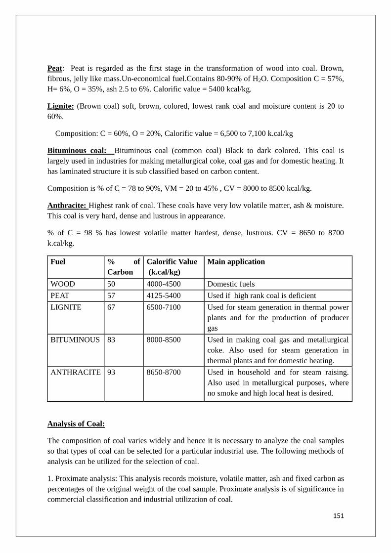
151
Peat: Peat is regarded as the first stage in the transformation of wood into coal. Brown,
fibrous, jelly like mass.Un-economical fuel.Contains 80-90% of H2O. Composition C = 57%,
H= 6%, O = 35%, ash 2.5 to 6%. Calorific value = 5400 kcal/kg.
Lignite: (Brown coal) soft, brown, colored, lowest rank coal and moisture content is 20 to
60%.
Composition: C = 60%, O = 20%, Calorific value = 6,500 to 7,100 k.cal/kg
Bituminous coal: Bituminous coal (common coal) Black to dark colored. This coal is
largely used in industries for making metallurgical coke, coal gas and for domestic heating. It
has laminated structure it is sub classified based on carbon content.
Composition is % of C = 78 to 90%, VM = 20 to 45% , CV = 8000 to 8500 kcal/kg.
Anthracite: Highest rank of coal. These coals have very low volatile matter, ash & moisture.
This coal is very hard, dense and lustrous in appearance.
% of C = 98 % has lowest volatile matter hardest, dense, lustrous. CV = 8650 to 8700
k.cal/kg.
Fuel % of
Carbon
Calorific Value
(k.cal/kg)
Main application
WOOD 50 4000-4500 Domestic fuels
PEAT 57 4125-5400 Used if high rank coal is deficient
LIGNITE 67 6500-7100 Used for steam generation in thermal power
plants and for the production of producer
gas
BITUMINOUS 83 8000-8500 Used in making coal gas and metallurgical
coke. Also used for steam generation in
thermal plants and for domestic heating.
ANTHRACITE 93 8650-8700 Used in household and for steam raising.
Also used in metallurgical purposes, where
no smoke and high local heat is desired.
Analysis of Coal:
The composition of coal varies widely and hence it is necessary to analyze the coal samples
so that types of coal can be selected for a particular industrial use. The following methods of
analysis can be utilized for the selection of coal.
1. Proximate analysis: This analysis records moisture, volatile matter, ash and fixed carbon as
percentages of the original weight of the coal sample. Proximate analysis is of significance in
commercial classification and industrial utilization of coal.

152
2. Ultimate analysis: This consists of determination of C, H, S, N and O. The ultimate
analysis is essential for calculating heat balances in any process for which coal is employed
as a fuel.
1. Proximate analysis: It is a quantitative analysis of the following parameters.
1. Moisture
2. Volatile matter
3. Ash
4. Fixed carbon
Moisture: About 1 gram of finely powdered air-dried coal sample is weighed in a crucible.
The crucible is placed inside an electric hot air-oven, maintained at 105 to 1100C. The
crucible is allowed to remain in oven for 1 hour and then taken out, cooled in a desiccator and
weighed. Loss in weight is reported as moisture.
Volatile Matter: The dried sample is taken in a crucible and then covered with a lid and
placed in an electric furnace or muffle furnace, maintained at 9250C. The crucible is taken out
of the oven after 7 minutes of heating. The crucible is cooled first in air, then inside
desiccator and weighed again. Loss in weight is reported as volatile matter on percentage-
basis.
Ash: The residual coal sample taken in a crucible and then heated without lid in a muffle
furnace at 750oC for ½ hour. The crucible is then taken out, cooled first in air, then in
desiccator and weighed. Heating, cooling and weighing is repeated, till a constant weight is
obtained. The residue is reported as ash on percentage-basis.
Fixed carbon: After the determination of moisture, volatile matter and ash contents, the
remaining material is known as fixed carbon. It is determined indirectly by deducting the sum
of the percentages of moisture, volatile matter and ash from 100

153
% of Fixed carbon = 100 - % of (Moisture + Volatile matter + ash)
Significance of Proximate Analysis: Proximate analysis provides following valuable
information in assessing the quality of coal.
1. Moisture: Moisture in coal evaporates during the burning of coal and it takes some of the
liberated heat in the form of latent heat of evaporation. Therefore, moisture lowers the
effective calorific value of coal. More over, it quenches the fire in the furnace, hence, lesser
the moisture content, better the quality of coal as a fuel.
2. Volatile matter: High volatile matter content means that a high proportion of fuel will
distil over as gas or vapour, a large proportion of which escapes un-burnt, So, higher volatile
content in coal is undesirable. A high volatile matter containing coal burns with a long flame,
high smoke and has low calorific value. Hence, lesser the volatile matter, better the rank of
the coal.
3. Ash: Ash is a useless, non-combustible matter, which reduces the calorific value of coal..
Hence, lower the ash content, better the quality of coal. The presence of ash also increases
transporting, handling and storage costs. It also involves additional cost in ash disposal.
4. Fixed carbon: Higher the percentage of fixed carbon, greater is its calorific value and
better is the quality of coal.
Ultimate analysis: This is the elemental analysis and often called as qualitative analysis of
coal. This analysis involves the determination of carbon and hydrogen, nitrogen, sulphur and
oxygen.
Carbon and Hydrogen:
About 1 to 2 grams of accurately weighed coal sample is burnt in a current of oxygen in a
combustion apparatus. C and H of the coal are converted into CO2 and H2O respectively. The
gaseous products of combustion are absorbed respectively in KOH and CaCl2 tubes of known
weights. The increase in weights of these are then determined.
C + O2 CO2
2KOH + CO2 K2CO3 + H2O
H2 + ½ O2 H2O
CaCl2 + 7 H2O CaCl2.7H2O
% of Carbon = Increase in weight of KOH
Weight of coal sample taken×
12
44× 100
% of Hydrogen = Increase in weight of CaCl 2 tube
Weight of coal sample taken×
2
18× 100

154
Nitrogen:
About 1 gram of accurately weighed powdered coal is heated with concentrated H2SO4 along
with K2SO4 (catalyst) in a long-necked Kjeldahl‟s flask. After the solution becomes clear, i.e,
when whole nitrogen is converted into ammonium sulphate, it is treated with excess of NaOH
and the liberated ammonia is distilled over and absorbed in a known volume of standard acid
solution. The unused acid is then determined by back titration with standard NaOH solution.
From the volume of acid used by liberated ammonia, the percentage of N2 in coal is
calculated as follows:
% of N2 = Volume of acid ×Normality of acid ×1.4
Weight of coal taken

155
Sulphur:
Sulphur is determined from the washings obtained from the known mass of coal, used in
bomb calorimeter for determination of a calorific value. During this determination, S is
converted into sulphates. The washings are treated with barium chloride solution, when
barium-sulphate is precipitated. This precipitate is filtered, washed and heated to constant
weight.
% of Sulphur =Wei ght of BaSO 4 obtained × 32
Weight of coal sample taken × 233× 100
Ash: The residual coal is taken in a crucible and then heated without lid in a muffle furnace
at 7500C for ½ hour. The crucible is then taken out, cooled first in air, then in a desiccator
and weighed. Heating, cooling and weighing is repeated, till a constant weight is obtained.
The residue is reported as ash on percentage-basis.
Thus,
Oxygen:
It is determined indirectly by deducting the combined percentage of carbon, hydrogen,
nitrogen, sulphur and ash from 100.
% of Oxygen = 100 – % of ( C + H + S + N + Ash)
Significance of Ultimate analysis:
Carbon and Hydrogen: Greater the percentage of carbon and hydrogen, better is the
coal in quality and calorific value. However, hydrogen is mostly associated with the
volatile mater and hence, it affects the use to which the coal is put.
Nitrogen: Nitrogen has no calorific value and hence, its presence in coal is undesirable.
Thus, a good quality coal should have very little nitrogen content.
Sulphur: Sulphur, although contributes to the heating value of coal, yet on combustion
produces acids like SO2, SO3, which have harmful effects of corroding the equipments
and also cause atmospheric pollution.
Ash: Ash is a useless, non-combustible matter, which reduces the calorific value of coal.
Moreover, ash causes the hindrance to the flow of air and heat, thereby lowering the

156
temperature. Hence, lower the ash content, better the quality of coal. The presence of ash
also increases transporting, handling and storage costs.
Oxygen; Oxygen content decreases the calorific value of coal. High oxygen-content coals
are characterized by high inherent moisture, low calorific value, and low coking power.
Moreover, oxygen is a combined form with hydrogen in coal and thus, hydrogen
available for combustion is lesser than actual one. An increase in 1% oxygen content
decreases the calorific value by about 1.7% and hence, oxygen is undesirable. Thus, a
good quality coal should have low percentage of oxygen.
LIQUID FUELS:
Petroleum or Crude oil
The crude oil or petroleum also known as rock oil or mineral oil is a dark colored
liquid found well deep in the earth.
It is mainly composed of hydrocarbons which may be solids, liquids or gases.
Some optical active compounds having S and N also present.
On average the composition of petroleum is
C= 79.5-87.1% H= 11.5-14.8%
S = 0.1-3.5% N and O = 0.1-0.5%
Origin of petroleum
The two theories which explain the formation of petroleum are
1. Carbide theory or Mendeleev‟s theory
2. Engler‟s theory or Organic theory
Carbide theory or Mendeleev’s theory:
This theory is known as inorganic theory of petroleum.
According to this theory the carbides which are formed from a reaction between carbon and
metals at high temperature and pressure are acted upon by steam to give hydrocarbons.
Ca+2C CaC2
4Al+3C Al4C3
CaC2 + 2H2O Ca(OH)2 + C2H2
Al4C3+12H2O 4Al(OH)3 + 3CH4
The unsaturated hydrocarbons which are produced along with the saturated hydrocarbons
react with hydrogen to produced saturated hydrocarbons.
C2H2 +H2 C2H4
C2H4 + H2 C2H6
The unsaturated hydrocarbons also get polymerized in the presence of metals.
3C2H2 C6H6

157
C2H4C6H12
This theory was unable to explain the presence of nitrogen, sulphur and optical active
compounds found in petroleum. This theory provides us a proof for the inorganic origin of
petroleum.
Engler’s Theory or Organic Theory
Organic matter, animals, vegetation and marine animals died and get accumulated in sea.
They were decomposed under high temperature and pressure by anaerobic bacteria to
give a dark viscous liquid called petroleum.
The existence of brine layer under petroleum and fossil remains of marine animals in
that areas suggest the organic origin of the petroleum
Refining of Petroleum:
Crude oil obtained from the mines contains lot of soluble and insoluble impurities
which must be removed. Refining can be defined as the processby which crude oil is
separatedinto various useful fractions by fractional distillation and finally converted into
desired specific products. The industry where the refining of crude oil takes place is called oil
refinery.
Refining of petroleum is done in different stages:
a. Removal of solid impurities: The crude oil is a mixture of solid, liquid and gaseous
substances. This is allowed to stand undisturbed for some time, when the heavy solid
particles settle down and gases evaporate. The supernant liquid is then centrifuged where
in the solids get removed.
b. Removal of water (Cottrell’s process): The crude oil obtained from the earth‟s crust is
in the form of stable emulsion of oil and brine. This mixture when passed between two
highly charged electrodes will destroy the emulsion films and the colloidal water droplets
coalesce into bigger drops and get separated out from the oil.
c. Removal of harmful impurities: In order to remove sulphur compounds in the crude oil,
it is treated with copper oxide. The sulphur compounds get converted to insoluble copper
sulphide, which can be removed by filtration.
d. Fractional distillation: Heating of crude oil around 4000C in an iron retort, produces hot
vapours which is allowed to pass through fractionating column. It is a tall cylindrical
tower containing a number of horizontal stainless trays at short distances and is provided
with small chimney covered with loose cap. As the vapours go up they get cooled
gradually and fractional condensation takes place. Higher boiling fractions condenses first
later the lower boiling fractions

158
Name of Fraction Boiling
range
Approx- composition
in terms of
hydrocarbon ‘C’
atoms
Uses
(1) Uncondensed gas
(2) Petroleum ether
(3)Gasoline or petrol
(4)Naphtha or solvent
spirit
(5) Kerosene
(6) Diesel oil
(7)Heavy oil on
refraction
(a) Lubricating oil
(b) petroleum jelly
c) Paraffin wax
d) Greases
8)Residue(asphalt,
petroleum coke)
Below
300C
300-70
0C
400-120
0C
120-180oC
1800C-
2500C
250-320oC
320-400oC
---
-----
C1toC4
C5-C7
C5-C9
C9-C10
C10-C16
C10-C18
C17-C30
…….
…….
A domestic or industrial fuel.
As a solvent.
As motor fuel, solvent, in dry
cleaning
As solvent, in dry cleaning
As an illuminant ,Engine fuel
Diesel engine fuel
Gasoline by cracking
As lubricant
As lubricant and in cosmetics
and ointments
In candles, boot polishes
As lubricant
Used for making tar roads,
water proof roofing

159
Synthetic petrol:
Because of increasing demand for petrol, the synthetic methods for preparation of petrol gain
more importance. The important processes commonly used for synthesis of petrol are
1. Fischer-Tropsch‟s method &
2. Bergius process.
1. Fischer-Tropsch’s method: This method was developed by Franz Fischer & Hans
Tropsch (German scientists). The raw material is the hard coke which is converted into water
gas (CO + H2) by passing steam over red hot coke.
In general, the mechanism of the reactions can be represented as
Ni or Co
nCO + 2nH2CnH2n + nH2O
nCO + (2n + 1) H2 CnH2n+2 + nH2O
Water gas (CO + H2)s is mixed with hydrogen gas (H2) in the presence of catalyst
Catalyst consists of mixture of 100 parts of Co, 5 parts of Th, 8 parts of MgO and 200
parts of Kieselguhr earth
Water gas and hydrogen gas mixture is purified by passing through Fe2O3 and Fe2O3
+ Na2CO3
Pressure is maintained to 5-25 atmosphere
Passed through a convertor where the catalyst and temperature are maintained at 200-
300oC.
In the convertor polymerization takes place
Hot gases are passed through a cooler where crude oil produced
Crude oil is fractionated in a fractionating column and the gasoline fraction is
produced in the top fraction

160
The high boiling heavy oil is obtained at the bottom can be used for cracking to get
more gasoline
Bergius Process
Low ash content coal is powdered and mixed with heavy oil to make paste along with
a catalyst (Ni or Sn oleate)
Paste is heated with H2 at 450oC and 200-250 atmospheric pressure in the convertor
The polymerized gases are passed through a cooler to get heavy oil
It is then subjected to fractional distillation to get the gasoline fraction at the top
portion
At the bottom heavy oil fraction left out can be made use for making the coal paste
again
The yield of gasoline obtained by this process is 60%
Cracking of Petrol :The quality and yield of petrol produced by the fractionation of
petroleum is low. Hence, the middle oil and heavy oil fractions are cracked to give petrol
Cracking is defined as the “decomposition of bigger hydrocarbon molecules into simpler, low
boiling hydrocarbons of low molecular weight”.
Cracking
Ex. C10H12C5H12 + C5H10
Decane Pentane Pentene
Advantages
The yield of petrol is higher.
The quality of petrol produced is better.
No external fuel is necessary for cracking.
Cracking can be easily controlled, so we can get desired products.
Evolution of by-product gases can be minimized.

161
Product contains very less quantity of undesirable sulphur content. So it is very
useful.
Objectives:
A product from crude oil, gasoline has greater demand as motor fuel. But yield is only upto
20%, more over fractional distillation have high content of sulphur. To overcome these
problems middle and heavy oil fractions are cracked to get petrol. The main objective of
cracking is to get desired products. Petrol made by cracking as good characteristics than
straight run petrol
Cracking is mainly two types:
a. Thermal cracking:In this process, heavier hydrocarbon molecules are converted into
lighter hydrocarbon molecules at high temperatures and pressures. Thermal cracking is
carried out in two ways. The cracked products are then separated by fractional distillation.
Generally, the yield is from 7to 30%. 1) Liquid phase thermal cracking 2) Vapour phase
thermal cracking
Liquid phase thermal cracking: In this method, cracking takes place at 4750C to 530
0C and
at a high pressure of 100kg/cm2. The cracked components have octane number up to 70.
Vapour phasethermal cracking: It is conducted for oils having low boiling
temperatures.The cracking occurs at 600 to 6500C and comparatively at low pressure of 10 to
20 kg/cm2. It requires less time and the petrol obtained has better antiknock properties and
poor stability than the petrol obtained from liquid phase thermal cracking.
Catalytic cracking: In this type of cracking catalysts are used. The suitable catalysts used
are Al2O3 and Al2(SiO3). This process completes at lower temperatures and low pressures
compared to thermal cracking (300-450oC;1-5kg/cm
2 pressure). The petrol sample produced
contains higher content of aromatics, hence quality of petrol with better antiknock
properties.The petrol sample contains less percentage of sulphur, hence less corrosive.
Catalytic cracking may be:
1) Fixed bed catalytic cracking
2) Moving bed catalytic cracking
Fixed bed catalytic cracking:
The oil vapours are heated in a pre-heater to cracking temperatures (420 – 4500C)
then forced through a catalytic chamber maintained at 425 – 4500C and 1.5 kg/cm
2
pressure.
During their passage through the tower, about 40% of the charge is converted into
gasoline and about 2 – 4% carbon is formed. The latter adsorbed on the catalyst bed.
The vapour produced is then passed through a fractionating column, where heavy oil
fractions condense.
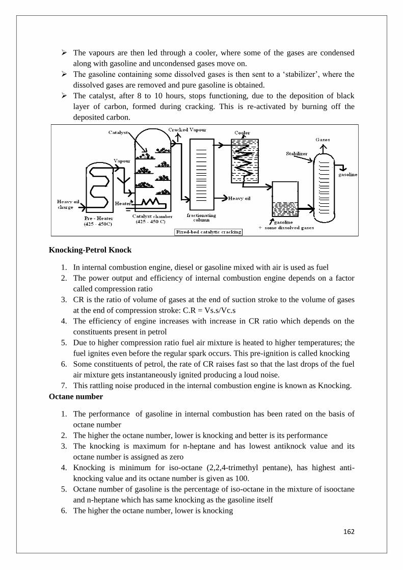
162
The vapours are then led through a cooler, where some of the gases are condensed
along with gasoline and uncondensed gases move on.
The gasoline containing some dissolved gases is then sent to a „stabilizer‟, where the
dissolved gases are removed and pure gasoline is obtained.
The catalyst, after 8 to 10 hours, stops functioning, due to the deposition of black
layer of carbon, formed during cracking. This is re-activated by burning off the
deposited carbon.
Knocking-Petrol Knock
1. In internal combustion engine, diesel or gasoline mixed with air is used as fuel
2. The power output and efficiency of internal combustion engine depends on a factor
called compression ratio
3. CR is the ratio of volume of gases at the end of suction stroke to the volume of gases
at the end of compression stroke: C.R = Vs.s/Vc.s
4. The efficiency of engine increases with increase in CR ratio which depends on the
constituents present in petrol
5. Due to higher compression ratio fuel air mixture is heated to higher temperatures; the
fuel ignites even before the regular spark occurs. This pre-ignition is called knocking
6. Some constituents of petrol, the rate of CR raises fast so that the last drops of the fuel
air mixture gets instantaneously ignited producing a loud noise.
7. This rattling noise produced in the internal combustion engine is known as Knocking.
Octane number
1. The performance of gasoline in internal combustion has been rated on the basis of
octane number
2. The higher the octane number, lower is knocking and better is its performance
3. The knocking is maximum for n-heptane and has lowest antiknock value and its
octane number is assigned as zero
4. Knocking is minimum for iso-octane (2,2,4-trimethyl pentane), has highest anti-
knocking value and its octane number is given as 100.
5. Octane number of gasoline is the percentage of iso-octane in the mixture of isooctane
and n-heptane which has same knocking as the gasoline itself
6. The higher the octane number, lower is knocking

163
7. The octane number of poor fuels can be raised by the addition of extremely poisonous
materials such as tetraethyl lead (C2H5)4Pb and diethyl-telluride (C2H4)2Te
8. The tendency of knocking is based on the chemical structure of hydrocarbons
n-paraffins> isoparaffins > Olefins > cycloparaffins > naphthalenes > aromatics
decreasing order of knocking
(isooctane) octane number 100 (good fuel) octane number zero (bad fuel)
Diesel Knock
Cetane Number
1. The quality or rating of diesel is expressed by cetane number. Cetane is n-
Hexadecane (C16H34)
2. Diesel knock is due to post-ignition (delayed ignition) of fuel air mixture with the
application of heat and pressure but not by spark as in petrol I.C engine
3. n-Hexadecane has a short ignition lag as compared to any commercial diesel fuel. Its
cetane number is 100
4. α -methyl naphthalene has very long ignition lag as compared to any commercial
diesel oil. Its cetane number is taken as zero
5. Cetane Number is the percentage of n-hexadecane in a mixture of n- hexadecane
and α-methyl naphthalene which has the same ignition characteristics as that of the
sample under test.
6. The order of cetane number for the following is given as:
7. n-alkanes > naphthalenes > alkenes > branched alkanes > aromatics
8. n-alkanes have good anti-knock value and aromatics have least anti-knock value
2-methyl naphthalene n-hexadecane
Cetane number = 0 (bad fuel)Cetane number = 100 (good fuel)
Petrol knocking is defined as the rattling sound produced in petrol engine due to
pre-ignition of fuel air mixture
Diesel knocking is defined as the rattling sound produced in diesel engine due to
ignition lag of fuel air mixture

164
Knocking is due to improper ignition of fuel –air mixture.
Knocking decreases the efficiency of engine.
Petrol Knock is maximum in open chain straight paraffins and least in aromatics
For internal combustion engine a fuel is said to be a good fuel if it has least knocking
S. No Petrol Knocking Diesel Knocking
1 Petrol knocking is due to pre-ignition of
the fuel
Diesel knocking is due to post-
ignition (ignition–lag) of the fuel
2. Octane number is the rating of petrol
knock
Cetane number is the rating of
diesel knock
3 Straight chain hydrocarbons causes
maximum petrol knock where as
aromatics causes least knock
Aromatic hydrocarbons causes
maximum diesel knock where as
straight chain hydrocarbons
causes least knock
4 To improve anti-kock value TEL, and
diethyl telluride are added
To improve antiknock value pre-
ignition dopes like ethyl nitrite,
isoamyl nitrite and acetane peroxide
are added
Prevention of Knocking: To improve the antiknock value of the petrol sample, Tetraethyl
lead (TEL) and diethyl telluride [(C2H5)2Te] are added
Knocking can be prevented by using:
i) Good quality fuel with higher octane number
ii) By adding anti-knocking agents like tetraethyl lead, diethyl telluride etc.
iii) By retarding spark plug ignition
Leaded petrol:The variety of petrol in which tetra ethyl lead is added is called leaded petrol.
Advantages: Usually petrol with low octane number is not good quality petrol. It often
knocks (i.e., produces huge noise due to improper combustion). As a result of knocking,
petrol is wasted; the energy produced cannot be used in a proper way.
When tetraethyl lead is added, it prevents knocking, there by saves money and energy.
Usually 1 to 1.5 ml of TEL is added per 1lit of petrol.
The mechanism of action is as follows:

165
First TEL will be transformed into finely divided particles of PbO which looks like a cloud.
This takes place in the cylinder. Then the PbO particles react with hydrocarbon peroxide
molecules formed, thus slowing down the oxidation process and prevent early detonation.
Thus either knocking may be stopped or greatly reduced.
Disadvantages: Deposits of PbO are harmful to engine. So PbO must be eliminated from the
engine. For this purpose, little amount of ethylene dibromide is added to petrol. It converts
the harmful PbO to volatile PbBr2 and eliminated through exhaust. Presence of any sulphur
compounds reduces the efficiency of TEL. However lead bromide is harmful to environment
Gaseous fuels
Eg: Natural Gas
1. Natural gas is primary gaseous fuel. It is a fossil fuel
2. It is obtained from oil wells dug in the earth crust during mining of petroleum
3. It is mainly composed of methane and small quantities of ethane along with other
hydrocarbons
4. It is also known as methane gas or marsh gas as it majorly contains methane
5. Composition of Natural gas:
CH4 - 88.5% C2H6 - 5.5% Propane - 3.7%
Butane - 1.8% H2, CO, CO2 - 0.5%
6.Calorific value varies from 12000-14000 Kg/m3
7. It is used as a very good domestic fuel
8. It is used in the preparation of ammonia
9. It is used to prepare carbon black for rubber industry
10. It is used to prepare some synthetic proteins which are used as animal feed
Secondary Gaseous fuels
LPG (Liquified Petroleum Gas): Characteristics
1. LPG is obtained as byproduct during refining of crude oil or from natural gas
2. It mainly contains n-butane , isobutane, butylene and propane
3. It has high calorific value: 27800 kcal/m3
4. It gives less CO and least un-burnt hydrocarbons. So it causes least pollution
5. It gives moderate heat which is very useful for cooking
6. It has a tendency to mix with air easily
7. Even though it is toxic, on combustion it gives no toxic gases
8. It neither gives ash or smoke content
9. It is cheaper than gasoline. Hence used as motor fuel
10. It is dangerous when leakage is there. It is highly knock resistant
11. LPG is used as domestic fuel and as a fuel in internal combustion engines
12. It is used as fuel in some industries

166
LPG can be compressed under pressure in containers and sold under the trade
name like Indane gas, Bharath gas etc.
Traces of smelling organic sulphides (mercaptons)are added to LPG for safety
measures(to give warning of gas leakage)
CNG (Compressed Natural Gas)
1. Natural gas mainly contains CH4. CNG is made by compressing natural gas to less
than 1% of the volume it occupies at STP
2. It is stored in a cylinder made of steel at a pressure of 200-248Kg/cm3
3. It is odourless, non toxic gaseous mixture
4. Composition of CNG is CH4 (90%), other constituents are ethane, propane and gases
like N2, CO etc.
5. Calorific value of CNG is 900KJ/mole
Advantages:
1. Due to higher temperature of ignition, CNG is better fuel than petrol and diesel
2. Operating cost is less
3. It releases least pollutants like CO and unburnt hydrocarbons
4. It mixes with air easily and undergoes regular combustion
5. No anti-knocking agent is required as it has high octane number
6. It is used as fuel in automobiles like cars, trucks, buses etc.
7. It is also used as fuel for locomotive diesel generators to generate electricity that drive
the motors of train
Flue gas Analysis
Gases after combustion contain CO, CO2, N2 etc. In order to know the exact details about any
fuel it is essential to analyze the flue gases. The mixture of gases mostly CO2 issuing out of
the combustion chamber is called flue gas. The efficiency of combustion can be well
understood by the analysis of flue gas. For instance, if the presence of CO is indicated then
carbon is suffering incomplete combustion due to insufficient supply of oxygen. But if the
analysis shows the excess of CO2, more of O2, it implies that oxidation is complete and the
supply of oxygen may be excessive. The analysis of flue gases is carried out with the help of
Orsat‟s apparatus.
1. Flue gas is a mixture of gases produced from the products of combustion of a fuel
2. Its major constituents are CO, CO2,O2, and N2
3. The efficiency of combustion can be understood by the qualitative analysis of flue
gases
4. Orsat‟s apparatus is used for flue gas analysis

167
Fig: Orsat’s Apparatus
Flue gas KOH sol Alk.Pyrogallic sol ammm.Cu2Cl2 sol
-CO2 –O2 -CO
Orsat’s apparatus: It consists of water – jacketed measuring burette, connected in series to a
set of three absorption bulbs, through stop cocks. The other end is provided with a three way
stop cock, the free end of which is further connected to a U – tube packed with glass wool
(for avoiding the incoming of any smoke particles, etc.) The graduated burette is surrounded
by a water jacket to keep the temperature constant of gas during the experiment. The lower
end of the burette in connected to a water reservoir by means of along rubber tubing. The
absorption bulbs are usually filled with glass tubes, so that the surface area of contact
between the gas and the solution is increased.
The absorption bulbs have solutions for the absorption of CO2, O2 and CO respectively. First
bulb has potassium hydroxide solution (250g KOH in 500ml of boiled distilled water), and it
absorbs only CO2. The second bulb has solution of alkaline pyrogallic acid (25g pyrogallic
acid + 200g KOH in 500 ml of distilled water) and it can absorb CO2 and O2. The third bulb
contains ammonium cuprous chloride (100g cuprous chloride + 125ml liquor ammonia + 375
ml of water) and it can absorb CO2, O2 and CO.
Hence, it is necessary that the flue gas is passed first through potassium hydroxide bulb,
where CO2 is absorbed, then through alkaline pyrogallic acid bulb, where only O2 will be
absorbed (because CO2 has already been removed) and finally through ammonical cuprous
chloride bulb, where only CO will be absorbed.
Working:
Step 1:
To start with, the whole apparatus is thoroughly cleaned, stoppers are greased and
then tested for air tightness. The absorption bulbs are filled with their respective

168
solutions to level just below their rubber connections. Their stop cocks are then
closed.
The jacket and leveling reservoir are filled with water. The three way stop cock is
opened to the atmosphere and reservoir is raised, till the burette is completely filled
with water and air is excluded from the burette.
The three way stop cock is now connected to the flue gas supply and the reservoir is
lowered to draw in the gas, to be analyzed, in the burette.
However, the sample gas mixed with some air present in the apparatus. So the three
way stop cock is opened to the atmosphere, and the gas expelled out by raising the
reservoir. This process of sucking and exhausting of gas is repeated 3-4 times, so as to
expel the air from the capillary connecting tubes etc.
Finally, gas is sucked in the burette and the volume of the flue gas is adjusted to
100ml at atmospheric pressure.
For adjusting final volume, the three way stop cock is opened to atmosphere and the
reservoir is carefully raised, till the level of water in it is the same as in the burette,
which stands at 100ml mark. The three ways stop cock is then closed.
Step 2: The stopper of the absorption bulb, containing caustic potash solution, is opened and
all the gas is forced into the bulb by raising the water reservoir. The gas is again sent to the
burette. This process is repeated several times to ensure complete absorption of CO2 [KOH
solution]. The unabsorbed gas is finally taken back to the burette, till the level of solution in
the CO2 absorption bulb stands at the fixed mark and then its stop cock is closed. The levels
of water in the burette and reservoir are equalized and the volume of residual gas is noted.
The decrease in volume gives the volume of CO2 in 100ml of the gas sample.
Step 3: The volumes of O2 and CO are similarly determined by passing the remaining gas
through alkaline pyrogallic acid bulb and ammonical cuprous chloride bulb respectively. The
gas remaining in burette after absorption of CO2, O2 and CO is taken as nitrogen.
Knowing the volume of the gases absorbed and volume of original gases, their
percentages can be calculated
Percentage of gas in the bulb, g = 𝑎/𝑚
𝑉 x100
Where a = amount of gas in the bulb (a = a1, a2, a3 - amount of gas in bulbs 1,2,3
respectively)
m = mass of gas in bulb (m = m1, m2, m3 – mass of gas in bulbs 1,2,3,respectively)
Calorific value: The prime property of a fuel is its capacity to supply heat. Fuels essentially
consists of carbon, hydrogen, oxygen and some hydrocarbons and the heat that a particular
fuel can give is due to the oxidation of carbon and hydrogen. Normally when a combustible
substance burns the total heat depends upon the quantity of fuel burnt, its nature, air supplied

169
for combustion and certain other conditions governing the combustion. Further the heat
produced is different for different fuels and is termed as its calorific value.
Calorific value of a fuel may be defined as “the total quantity of heat liberated, when
a unit mass (or volume) of a fuel is burnt completely”. Or
“Calorific value is the amount of heat liberated by the complete combustion of a unit
weight of the fuel and is usually expressed as cal gm-1
or kcal gm-1
or B.Th.U. Or
The calorific value of a fuel can be defined as “the total quantity of heat liberated
when a unit mass of the fuel is completely burnt in air or oxygen”.
There are different units for measuring the quantity of heat. They are:
1. Calorie
2. Kilocalorie
3. British thermal unit (B.Th.U)
4. Centigrade heat unit (C.H.U)
1. Calorie: It is the amount of heat required to increase the temperature of 1 gram of water
through one degree centigrade.
2. Kilocalorie: This is the unit of heat in metric system, and is defined as the quantity of heat
required to raise the temperature of one kilogram of water through one degree centigrade.
1 k.cal = 1000 cal
1 k.cal = 3.968 B.Th.U
3. British thermal unit (B.Th.U): This is the unit of heat in English system, it is defined as
“the quantity of heat required to increase the temperature of one pound of water through one
degree Fahrenheit.
1 B.Th.U = 252 cal = 0.252 k.cal
4. Centigrade heat unit (C.H.U): It is the quantity of heat required to raise the temperature
of one pound of water through one degree centigrade.
1 k.cal = 3.968 B.Th.U = 2.2 C.H.U
Inter conversion of various units of heat:
1 k.cal = 1000 cals = 3.968 B.Th.U = 2.2 C.H.U1 B.Th.U = 252 cals
Units of calorific value:
For solid or liquid fuels: cal/g or k.cal/kg, B.Th.U/lb

170
For gaseous fuels: k.cal/cubic meter or k.cal/m3
B.Th.U/ft3 or B.Th.U/cubic feet
There are two types of calorific values of a fuel
1) Higher Calorific value (HCV) or Gross calorific value (GCV)
2) Lower Calorific value (LCV) or Net calorific value (NCV)
Higher or Gross calorific value(HCV):
It is defined as the total amount of heat produced when unit mass or unit volume of fuel is
completely burnt and the products of combustion are allowed to cool to room temperature.
When a fuel containing hydrogen is burnt, the hydrogen present is converted to steam. As the
products of combustion are cooled to room temperature, the steam gets condensed into water
and the latent heat is evolved. Thus the latent heat of condensation of steam, so liberated, is
included in the gross calorific value.
Net calorific value or lower calorific value (LCV)
Whenever a fuel is subjected to combustion, the water vapour and moisture etc., escape along
with the hot combustion gases and hence there is no chance for them to condense. So the net
or lower calorific value is defined as “the net heat produced, when unit mass or unit volume
of the fuel is burnt completely and the combustion products are allowed to escape.
Relationship between HVC and LCV
LCV or NCV = HCV – Latent heat of water vapour formed
H2 + 1/2O2 H2O
2 gm 18 gm
1 gm 9 gm
Since 1 part by mass of hydrogen produces 9 parts by mass of water
Hence LCV = HCV – mass of hydrogen x 9 x latent heat of steam
Latent heat of steam is 587kcal/g.
Net calorific value = Gross calorific value – 9 x H/100 x 587
Where H = % of hydrogen in the fuel
Determination of Calorific Value:
The calorific value of a fuel is determined by an apparatus called calorimeter
NCV = GCV – 0.09 x H x 587
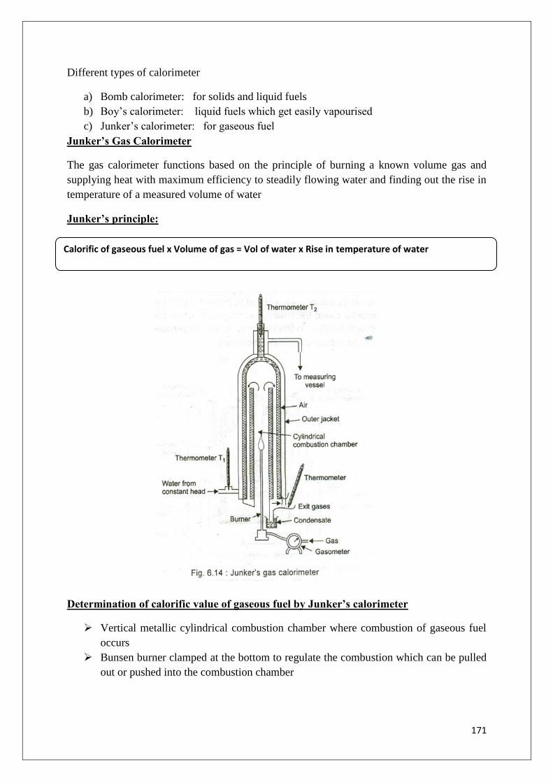
171
Different types of calorimeter
a) Bomb calorimeter: for solids and liquid fuels
b) Boy‟s calorimeter: liquid fuels which get easily vapourised
c) Junker‟s calorimeter: for gaseous fuel
Junker’s Gas Calorimeter
The gas calorimeter functions based on the principle of burning a known volume gas and
supplying heat with maximum efficiency to steadily flowing water and finding out the rise in
temperature of a measured volume of water
Junker’s principle:
Determination of calorific value of gaseous fuel by Junker’s calorimeter
Vertical metallic cylindrical combustion chamber where combustion of gaseous fuel
occurs
Bunsen burner clamped at the bottom to regulate the combustion which can be pulled
out or pushed into the combustion chamber
Calorific of gaseous fuel x Volume of gas = Vol of water x Rise in temperature of water

172
Supply of gas is regulated with the help of manometer which controls the supply of
gas at a given pressure andgasometer is used to measure the volume of gas flowing in
a particular time
Combustion chamber is surrounded by annular space for water circulation
Heat loss is prevented with the help of an outer jacket made of chromium plate
Two thermometers are placed to measure the temperature of outlet and inlet water.
Procedure:
A known volume of gas is burned in excess of air at a constant rate in combustion chamber
in such a manner that all the heat produced is absorbed in water. Water is flowing at a
constant rate in annular space around the combustion chamber. The increase in the
temperature of the water is measured and the heat evolved from the burning of the gas can
be readily calculated. The weight of water flowing is also recorded for the calculation of
calorific value of gaseous fuel.
Experimental caluculations
V = Volume of gas burnt in certain time „t‟
W = Weight of water collected in time „t‟
t1 = Temp of incoming water
t2 = Temp of outgoing water
Rise in temp = t2 - t1
If L kcal/m3
is the calorific value of gaseous fuel,
Heat produced by fuel = V x L
Heat absorbed by water = W x (t2 – t1)
By principle, Heat given = Heat absorbed
V x L = W x (t2 –t1)
C.V of gas (L) HCV = W x (t2 –t1) kcal/m3
V
Mass of steam condensed in certain time„t‟ = m/v
If Latent heat of steam = 587kcal/kg,
= m/v x 587
LCV = HCV – m/v x 587 kcal/m3
Theoretical Calculation of Calorific value:
The calorific value of a fuel can be approximately calculated by noting the amount of the
components constituting the fuel.
173
C + O2CO2 + 96960 calories
12 gm 32 gm 44gm
1 gm 96960/12 = 8080 calories
So 1 gm of carbon gives 8080 calories of heat. Similarly, H2 burns in the presence of O2,
resulting in the formation of water
H2 + ½ O2 H2O + 69000 calories
2gm 32gm 18gm
1gm 69000/2 =34500 calories
So 1gm of hydrogen when burnt gives 34500 calories of heat. The end products of the fuels
mostly happen to be water and CO2. Hence with the knowledge of their heats of combustion,
we can approximately find the calorific value of any fuel.
Dulong’s Formula
In this formula the higher calorific value of a fuel is the total of the calorific value of
each of the components. Secondly 8 parts of O2 combine with one part by weight of
hydrogen. So if oxygen is present, it must be present in combined form with hydrogen as
water thereby decreasing the amount of hydrogen available for combustion by O/8. The
formula is then:
GCV or HCV = 1/100[8080 C + 34500 (H-O/8) + 2240 S] cal/gm
Where C, H, O, S are percentages of carbon, hydrogen, oxygen, and sulphur respectively.
Combustion
Combustion is an exothermic chemical reaction accompanied by the increase of heat.
The gaseous products of combustion are mainly CO, CO2, N2, O2, SO2, which are mainly
known as flue gases
Calculations on combustion:
The main elements present in most of the fuels are C, H, O and S. On combustion of
fuel these elements are converted into gases like CO2, H2O, SO2.
1) Combustion of Carbon:
C + O2 CO2
12 32 44
12 kg of carbon requires 32 kg of oxygen for complete combustion
∴C kg of carbon requires oxygen for complete combustion = 32/12 x C kg ……(1)

174
2) Combustion of Hydrogen:
2H2 + O2 2H2O
4 32 36
4 kg of Hydrogen requires oxygen for complete combustion = 32 kg
∴H kg of Hydrogen requires oxygen for complete combustion = 32/4 x H
From the total amount of hydrogen in the fuel, part of Hydrogen are non combustible
in the form of water.
8 parts of oxygen combines with 1 part of Hydrogen
∴The amount of Hydrogen available for combustion = (H – O/8)
Hence oxygen required for combustion of Hydrogen = 32/4 (H – O/8)
= 8(H – O/8) kg….(2)
3) Combustion of Sulphur:
S + O2 SO2
32 32 64
32 kg of sulphur requires oxygen for complete combustion = 32 kg
∴S kg of sulphur in the fuel requires oxygen for complete combustion = 32/32 x S kg
= S kg….. (3)
On combining the above three combustion equations we get the equation for the
theoretical oxygen required for the combustion of C, H and S
= 32/12 x C + 8(H - O/8) + S
Air contains 23% by weight of oxygen and 21% by volume of oxygen
∴Minimum weight of air required for combustion
= 100/23 x [32/12 + 8(H – O/8) + S]
∴Minimum volume of air required for combustion
= 100/21 x [32/12 + 8(H – O/8) + S]
Numerical Problems:
Example 1: A sample of coal contains the following composition; Carbon= 84%; Hydrogen
= 12%, Oxygen = 2%, Sulphur = 1% and the remainder being ash. Calculate the gross and net
calorific values of the fuel.
Solution:
HCV = 1/100[8080 C + 34500 (H-O/8) + 2240 S] kcal/kg
= 1/100[8080 x 84 + 34500 (12-2/8) + 2240 x1] kcal/kg
= 1/100[ 678720 + 34500 x 11.75 + 2240]
= 1/100[ 678720 + 52875 + 2240]
= 1/100 x 733835 = 7338.35 kcal/kg
LCV = HCV – 0.09 x H x 587
= 7338.35 – 0.09 x 12 x 587

175
= 7338.35 – 633.96 = 6704.39 kcal/kg
Example 2:A sample of coal was found to have the following percentage composition: C =
85% H = 10% O = 3%. Calculate the minimum wt of air required for complete combustion of
1 kg of coal.
Solution:
1 kg of coal contains:
85% C = 0.85 kg
10% H = 0.1 kg
3% O = 0.03 kg
The net O2 required for complete combustion
= [32/12 x C + 8(H - O/8) + S] – O2 present in 1 kg of coal
= [ 32/12 x 0.85 +8(0.01 – 0.03/8) + 0 ] – 0.03
= 3.028 kg
∴ Minimum wt of air required for complete combustion of 1 kg of coal
= 100/23 x Net O2 required
= 100/23 x 3.028
= 13.165 kg

176
UNIT 5
PHASE RULE AND SURFACE CHEMISTRY
Introduction:
Phase rule is an important tool used for quantitative treatment of systems in equilibrium. It
enables to predict the conditions that must be specified for a system to exhibit equilibrium.
Phase diagrams are of considerable significance both industrially and commercially,
particularly for steels, alloys ceramics and semiconductors. These are the basis of separation
procedures in petroleum industry, food formulations and in the preparation of cosmetics.
Phase diagrams are an important tool to deal with the behavior of heterogeneous systems.
Phase rule helps in predicting the effect of temperature, pressure and concentration on
heterogeneous system in equilibrium
Phase Rule: The phase rule is a generalization put forward by Willard Gibbs in 1847 which
explains the equilibrium existing in heterogeneous system.
The phase rule is defined as if an equilibrium is dependent only on temperature,
pressure and concentration variations and is not influenced by gravity, surface forces,
electrical or magnetic forces then the number of degrees of freedom(F) of the system is
related to the number of components(C) and phase(P) by the phase rule equation.
Where,
F = number of degree of freedom or variables
C = no. of components of the system
P = no. of phases of the system
Terms Involved in Phase Rule
Phase: Phase can be defined as a homogenous, physically distinct and mechanically
separable portion from other parts of the system by definite boundary surfaces.
Examples:
1) At freezing point water exists in three phases
Ice ↔ water ↔ water vapour
(solid) (liquid) (vapour)
2) If two liquids are completely miscible it is said to exist in one phase only.
Ex: water- alcohol – homogenous system.
3) If two liquids are immiscible they are said to exist in two phases.
F = C- P + 2

177
Ex: Benzene – water – heterogonous system.
4) A solution of a substance in a solvent is said to exist in a single phase.
Ex: sugar dissolved in water
5) A gaseous mixture is said to exist in a single phase only
Ex: mixture of nitrogen and hydrogen
6) Different solid components constitute separate phase while different gaseous
constituents are considered as single phase
Ex: CaCO3(s) ↔ CaO(s) + CO2(g) → 3 phases
Component(C) :
The number of components in a system is the minimum no. of independently variable
chemical species by means of which the composition of each phase can be expressed.It is an
element or compound present in a system.
Eg:1. In water system all three phases ice, water and vapour has the same chemical
composition H2O. The composition of each phase can be expressed in terms of single
constituent represented byH2O.Hence it is a one- component system.
Eg:2. If we take Na2SO4-water system to describe the composition of different phases two
independently variable chemical species Na2SO4 and H2O are required Hence it is a two –
component system.
Na2SO4(s) + 7H2O ↔ Na2SO4.7H2O(s)
Phase Component
Na2SO4.7H2O = Na2SO4+7H2O
Na2SO4 = Na2SO4+OH2O
Solution = xNa2SO4+yH2O
3) Dissociation of ammonium chloride, which is in equilibrium with its products
ammonia and hydrochloric acid
NH4Cl ↔NH3(g) + HCl(g)
The composition of all the phases can be stated in terms of NH4Cl only. Hence C=1
4) Decomposition of CaCO3: There are 3 chemical species CaCO3, CaO and CO2. But the
composition of each phase can be expressed in terms of any two of the species.

178
PHASE COMPONENT
CaCO3 → CaO + CO2
CO2 → CaCO3 – CaO
CaO → CaCO3 –CO2
Components (C):
In a chemically reactive system involving reactions between various species, the number of
components of a system may be defined as the number of chemical constituents of the system
minus the number of equations relating to these constituents in a equilibrium state.
In a chemically reactive system, the number of components is given by
Where N: No. of chemical species
E: No. of independent equations relating the conc. of N species.
Examples:
(1). Dissociations of NH4Cl in a closed vessels
NH4Cl(s)↔NH3(g) + HCl(g)
The proportions of NH3 and HCl are equivalent
[NH3] = [HCl]
∴ N = 3 (NH4Cl,NH3 and HCl)
E = 2
∴C = N – E
= 3-2 = 1, i.e. it is a one component system.
(2). When NH4Cl is heated in a closed vessel along with NH3 or HCl.
NH4Cl(s)↔xNH3(g) + y HCl(g) – (i)
[NH3] ≠ [HCl]
∴Only one equations (i) relates the concentration of constituents
∴ C = 3 – 1 = 2
∴ The system has two components.
C = N – E

179
(3). KCl – NaCl – H2O system
N = 3 (i,e. KCl, NaCl, H2O)
Since there is no independent equation relating their concentrations.
∴ E = O
∴ C = 3 – 0 = 3
∴ System is a 3- component system
For KCl – NaBr – H2O system
N = 5 (i,e. KCl, NaBr, NaCl, KBr, H2O)
E= 1 (i,e. KCl + NaBr↔KBr + KCl
∴ C =N – E = 5 – 1 = 4
This system is regarded as a 4component system.
Degree of freedom:
It is defined as, “the minimum number of independently variables such as pressure
temperature and composition that must be specified in order to define the state of the system
completely.
If degree of freedom F=0, the system is known as non-variant or invariant
If F=1, then the system is invariant
If F=2, then system is bivariant
Examples:
1) In the water system
Ice (s) ↔ Water (l) ↔ Vapour (g)
Three phases will be in equilibrium only at particular temperature and pressure. The system
is, zero variant, or non-variant or invariant and has no degree of freedom.
2) For a system consisting of water in contact with its vapour.
Water (l) ↔ Vapour (g)
We must state either temperature or pressure to define the system completely. Hence the
degree of freedom is one (or) the system is univariant.
3)For a gaseous mixture of N2 and H2, we must state both the temperature and pressure.
Hence, the system is bivariant (degree of freedom is two).

180
Merits of phase rule
1. It is applicable to both physical and chemical equilibria.
2. It is a convenient method of classifying the equilibrium states in terms of phases,
components and degree of freedom.
3. It indicates different system with same degree of freedom behave similarly.
4. It helps us to predict the behaviors of a system, under different sets of variables.
5. It helps in deciding whether the number of substances remains in equilibrium or not.
Limitations of phase rule
1. It can be applied only for heterogeneous systems in equilibrium.
2. Only three variables like P, T, & C are considered, but not electrical, magnetic and
gravitational forces.
3. It is applied only to a single equilibrium system.
4. It requires utmost care in deciding the number of phases existing in equilibrium.
5. Solid and liquid phases must not be in finely divided state, otherwise deviations occur.
6. Only three degrees of freedom are allowed to influence the equilibrium system.
Applications of Phase rule:
1. Useful in understanding the properties of materials such as metals, alloys and composites
2. Used in several metallurgical processes, solvent extraction and steam distillation
3. In quality control of ultra pure materials like semiconductors, it is used to check impurity
concentration
Derivation of Phase Rule:
Consider a heterogeneous system in equilibrium of „C‟ components in which „P‟ phases are
present.
To determine of degree of freedom of this system i.e. the number of variable which
must be arbitrarily fixed in order to definethe system completely, we must know the
minimum number of variables. But the number of these variables is equal to the total
number of variables minus the number of relations between them at equilibrium
The state of the system will depends upon the temp &pressure, these two variables are
considered always. The concentration variables however depend upon the number of
phases.
In order to define the composition of each phase it is necessary to specify the
concentration of (C-1) constituent, the concentration of the remaining component
being determined by difference.
For „P‟ phase the total no. of concentration variables will be P(C-1) and these along
with the two variables they are temp & pressure.
Hence, total No. of variables = 1(for temp) +1 (for pressure) +P(C-1) [For
composition]
= [P(C-1) +2]

181
According to thermodynamics, when a system is in equilibrium the chemical potential
(𝜇) of the given component must the same in every phase.
Suppose the system consists of three phases a,b and c in equilibrium at a definite pressure
&temp , then the chemical potential of the given components is the same in each phase.
The components are designated by 1, 2, 3 then
𝜇1(a) = 𝜇1(b)−−−−−−−− −−−
𝜇2(a) = 𝜇2(b)−−−−−−−− −−−
𝜇3(a) = 𝜇3(b)−−−−−−−− −−−
And also
𝜇1(a)= 𝜇1(b)=𝜇1(c)
In general for the system of „P‟ phases and „C‟ components the system being in equilibrium
may be
𝜇1(a)= 𝜇1(b)= 𝜇1(c)=--------------------------=𝜇1(p)
𝜇2(a)= 𝜇2(b)= 𝜇2(c) = ------------------------ =𝜇2(p)
--------------------------------------------------------------
--------------------------------------------------------------
𝜇c(a)= 𝜇c(b)= 𝜇c(c)=--------------------------=𝜇c(p)
Hence for P phases the number of relationships for each component are (P-1)
For each component, there are P-1 separate equations. Hence for „C‟ components the number
of such equations are “C(P-1)”
Degree of freedom, F = Total No. of variables- No. of relationships between these variables
F = [P(C-1) +2]-[C (P-1)]
= PC- P + 2 – CP + C
F = C – P + 2
This is phase rule equation as stated by W. Gibbs
For a one component system, the phase rule equation is:
F= C−P + 2 = 1−P + 2 = 3−P
182
PHASE DIAGRAM
A diagram which illustrates the conditions of equilibrium between various phases of a
substance is called a phase diagram or equilibrium diagram.
A polyphasic equilibrium which can be studied with the help of any two intensive
properties, temperature and pressure and pressure or temperature and composition or
pressure and composition are represented by a two dimensional phase diagram
A diagram which illustrates the condition of equilibrium between various phases of a
substance is called a phase diagram.
A phase diagram is a graphical representation of chemical equilibrium.
Hence a phase diagram is a plot showing the conditions of pressure and temperature
under which two or more physical states can exist together in a state of dynamic
equilibrium.
The diagram consists of
a) the regions or areas
b) the lines or curves and
c) the point
One-component system:
In any system, the minimum number of phases is one. It is evident from the phase rule
equation
F = C-P+2
=1-1+2=2
For one component system the maximum number of degree of freedom is two.
The maximum number of phases in any system is three, from the phase rule equation
F = C – P+2
=1-3+2=0
The minimum number of degree of freedom is zero for one component system.
From the above calculations, it is clear that for any one-component system the maximum
number of degree of freedom is two. Therefore, such a system can be presented completely
by a two dimensional diagram. Hence, we may draw the phase diagram by taking pressure
and temperature as the two axes. These are known as pressure-temperature (P-T) diagrams,
concentration (or) compositionremains constant.
Water system:
Water can exist in three possible phases, namely, solid, liquid and vapour. Water system is a
typical example for one component system. It shows the following different equilibria

183
1. Liquid ↔ Vapour
2. Solid ↔ Vapour
3. Solid ↔ Liquid
Phase diagram for water system
Phase diagram consists of
Curves Areas Point
OA = Vapourisation curve AOB = vapour only O = Triple point
OB = Sublimation curve BOC = Ice only
OC= Fusion curve AOC = Liquid only
OA1= Meta stable curve
Each equilibrium involves two phases. It shows the relation between the solid, liquid and
gaseous states of a substance as a function of temp and pressure
Vapourisation curve OA:
It is called the vaporization curve of water
It represents the equilibrium between liquid water and vapour.
At any point on the curve the following equilibrium will exist.
Liquid water ↔ vapour

184
Water at any given temperature is associated with vapour pressure. With increase in
temperature, there is an increase in vapour pressure. The rate of increase is higher at higher
temperature than at lower temperature. This increasing trend continues till the system reaches
a critical temperature of 374oC and a critical vapour pressure of 218 atm. Beyond point A, the
two phase liq water and vapour merge into each other and only vapour phase exists. It is not
possible to liquefy water vapour beyond 374oC by the application of any amount of pressure.
The degree of freedom of the system is one, i.e., invariant. This is predicted by the phase rule.
F=1-2+2; F=1
Sublimation Curve ‘OB’:
It is called the sublimation curve or vapour pressure curve of ice.
It represents the equilibrium between ice and vapour.
At any point on the curve the following equilibrium will exist.
Ice ↔ Vapour.
With decrease in temperature initially the vapour pressure drops steeply followed by slow
decrease. Therefore this curve has positive slope. The curve starts at „O‟ and ends at „B‟ i.e.is
at absolute zero (-273oC). At this point no vapour can exist and therefore only ice is present.
The degree of freedom of the system is one i.e. univariant. This is predicted by the phase rule.
∴F = C-P+2; F = 1-2+2; F = 1
Fusion Curve OC:
It is called the fusion curve or melting point curve of ice
It represents the equilibrium between ice and water.
At any point, on the curve the following equilibrium will exist.
Ice ↔ water
It indicates the effect of pressure on the melting point of ice. As ice occupies more volume
than liquid water, according to Le-Chatelier‟s principle any rise in pressure shifts the
equilibrium in favour of liquid water. This is seen by the sloping of the curve OC towards the
vapour pressure axis indicating melting point of ice is decreased by increasing pressure.
Therefore the fusion curve has a negative slope.
∴F = C – P+2
= 1 -2 +2 = 1
∴It has one degree of freedom and the system is univariant
Metastable curve OA1:
Water always does not freeze at 0oC.Some times, water can be cooled below its freezing
temperature, ie water can be super cooled by carefully eliminating solid particles.
185
The curve OA represents vapour pressure curve of super cooled water.
Along the OA1, the super cooled liquid is in metastable equilibrium with vapour. As
soon as small particle of ice is kept in contact with super cooled liquid, it changes into ice and
the curve merges in OB.
At any point on the curve the following equilibrium will exist.
Super-cool water ↔ vapour
The degree of freedom of the system is one i.e., univariant.
Triple point:
The curves OA, OB, OC and OA1 meet at point O, and this point of intersection is
called the Triple point where all three phases, ice, water and vapour are in equilibrium.
The Temperature and pressure at the triple point of water are 0.0098oC and 4.58 mm
respectively.
According to phase rule, the degree of freedom is zero i.e., invariant.
∴F = C-P+2; F=1-3+2; F = 0
Thus the triple point represents an invariant system, i.e. any variation in even one of the
variable (either pressure or temperature) breaks the three phase equilibria and transforms into
a two phase equilibria represented by the curves
Areas:
AOB, AOC and BOC contain vapour, liquid and ice phases respectively, within these single
phase areas, the system is bivariant. This is predicted by the phase rule.
∴F=C-P+2; F=1-1+2; F=2
To locate any point in an area, temperature and pressure needs to be known.
Two – Component system:
In a two-component system, when P=1
Then F= C- P+2
= 2 – 1 + 2 = 3
This means that three variables must be specified in order to describe the state of the phase.
For graphical representation of these variables on a phase diagram requires a 3-dimensional
solid model phase diagram of a binary system should be represented by a three dimensional
diagram of temperatures, pressure and composition, which cannot be drawn on paper. In
order to simplify the system, the phase diagrams are represented in a two-dimensional way-
considering only two variables, the third one being a constant.

186
If pressure is kept constant, the phase diagram is called Isobaric
If temperature is kept constant, it is called isothermal and
If composition is kept constant, the phase diagram is called isoplethal.
Condensed system
For two- component solid/liquid system, the gas phase is usually absent and the effect of
pressure on the equilibrium is very small. Then it is necessary to consider the other two
variables, i,e. temperature & concentration. Such a solid/liquid system with the gas phase
absent is called a condensed system. The degree of freedom in such system is reduced to one
and the corresponding phase rule equation is called reduced or condensed phase rule and it is
written as
Types of two-component system:
TYPE A: When the components are completely miscible with one another in liquid state and
they do not form any compound and on solidification they give rise to intimate mixture
known as eutectic.
Eg: Pb – Ag, Pb – Sn, KI – water system
TYPE B: System in which the two components form a stable compound.
Eg: FeCl3 – water system, Zn – Mg system
NaCl - water system
SILVER – LEAD SYSTEM:
Silver – lead system is an example for two – component system.
The four possible phases of silver – lead system are
(i) solid silver (ii) solid lead (iii) solution of silver & lead in molten state (iv) vapour.
The boiling points of silver and lead being very high, vapour phase is practically
absent. Thus Ag/Pb system can be considered as condensed system with three phases. In such
condensed system, pressure changes have negligible impact on the system. Hence phase
diagram is plotted between temperature and composition at constant pressure of 1 atm. So for
silver – lead system „P‟ is negligible.
∴Isobaric phase diagram are studied and condensed phase rule equation is applied.
F1 = C – P + 1

187
Phase diagram-Ag/Pb system
The phase diagram consists of
(1) Two curves OA, & OB
(2) Five areas: AOB, BOD, AOC, COE, & DOE
(3) Eutectic point „O‟
Curve ‘OA’: It is the melting point curve or freezing point curve of Ag. The point A
represents the melting point of pure silver (M.P = 961oC). The melting point of silver falls
gradually by the addition of lead till the silver melt gets saturated with lead as represented by
the curve OA. Any further addition of lead beyond O, it simply separates out as solid Pb. This
saturation limit is represented by „O‟ is called the eutectic point.
Along „OA‟ solid silver & melt of silver & lead are in equilibrium. So the system is
two phase, two component system.
∴ F1
= C – P + 1
= 2 – 2 + 1 = 1
Hence the curve „OA‟ represent a univariant system, where fixing any one of the variable,
automatically fixes the other variable and even a slight variation of the variable leads to the
total disappearance of one of the phases.
Curve ‘OB’:
This is freezing point or melting point curve of Pb. The point B represent the melting
point of pure lead (M.P = 327oC). By the gradual addition of silver, melting point of lead
falls, till the lead melt gets saturated with silver. Any further addition of silver beyond O,
simply separate out as solid Ag.

188
Along curve OB, solid lead and melt of silver & Pb are in equilibrium.
∴ F1 = C – P + 1
= 2 – 2 + 1 = 1
∴ The system is univariant.
EUTECTIC POINT’O’:
The curves OA & OB meet at eutectic point „O‟. At „O‟ the silver solution becomes
saturated with lead and lead solution becomes saturated with silver. On further addition of
silver or lead, solid will get separated out. This saturation limit is represented by „O‟
called eutectic point.
At this point all 3 phases i.e; solid Pb, solid Ag and liquid solution are in equilibrium
On applying reduced phase rule equation
F1 = C – P + 1
= 2 – 3 + 1 = 0
Hence point „O‟ represents an invariant system, where any minor variation in one of the
variables disturb the three phase equilibrium resulting ina atom phase equilibrium.
The temperature and composition of the eutectic mixture corresponding to eutectic point
O at 1atm Pressure are 303oC and 2.4% Ag + 97.6% Pb respectively.
The eutectic point refers to lowest freezing point of liquid mixture of two metals.
If the temperature is raised above eutectic temperature, the solid phases Ag & Pb
disappear and if the system is cooled below the eutectic point, only solid Ag/Pb exists
where solution phase is non-existent.
Area AOB: This area represents a homogenous solution of Ag &Pb.
∴ F1 = C – P + 1
= 2 – 1 + 1 = 2
The system is bivariant
Area AOC: The area AOC has solid Ag & liquid melt in equilibrium.
∴ F1 = C – P + 1
= 2 – 2 + 1 = 1
System is univariant
Area BOD: The area BOD has solid lead & liquid melt in equilibrium.
∴ F1 = C – P + 1

189
= 2 – 2+ 1 =1
System is univariant
Area COE: The area COE has solid eutectic and solid Ag in equilibrium and the system is
univariant (F1 = 2 – 2 + 1 = 1)
Area DOE: The area has solid lead &solid eutectic in equilibrium. This is also a univariant
system like area COE.
EUTECTIC SYSTEM:
1. Eutectic means easy to melt (Greek: eutectos = easy melting)
2. A system in which two components are miscible in all proportions in the liquid state, but
do not react chemically and each component reduces the melting point of other is called
eutectic system.
3. A solid solution of two- component system having the lowest freeing point is called
„Eutectic mixture‟.
4. The lowest freezing point that can be obtained corresponding to eutectic mixture is known
as „Eutectic point‟. At the eutectic point three phases co-exist.
∴F1 = C – P + 1 = 2 – 3 + 1 = 0 (a non-variant or invariant point)
Characteristics of Eutectic Point:
1. Eutectic point refers to lowest freezing point of a liquid mixture of any two metals at
agiven pressure.
2. Below the eutectic temperature, no liquid phase of any composition can exist in the
system.
3. The system is invariant at the eutectic point and it has definite values of temperature and
composition.
4. Similar to molten metal, eutectic mixture freezes at a constant temperature. The solid
eutectic so formed has a fixed composition and is called an alloy.
5. If the liquid melt of the two components is cooled just below the eutectic point, both the
components solidify in the form of small crystals without any change in composition.
6. Because of their crystal characteristics, the eutectic mixtures of alloys have greater
strength than their components.
7. Inspite of having a definite composition and fixed freezing point eutectic mixture is never
considered as a compound as the crystals of components are clearly under microscope.
Applications of Eutectic system:
1. Eutectic mixture composed of alloys are used as safety devices in boilers, as plugs in
automobiles.
2. Because of their low melting points eutectics are also used in preparing solders which are
used in joining two metal pieces together. Eg: lead – tin solders.
3. They are also used in safety fuses used in building to protect them against fire hazards.

190
Eg: Wood metal, which is an alloy of 50%, Bi + 25%, Pb + 12.5%, Sn + 12.5% Cd.
Application of Ag-Pb System in Desilverisation of Pb (or) Pattinson’s
Process:
The principle of (Ag-Pb) system is utilized in the pattinson‟s process of
desilverisation of lead.
During extraction of Pb from its ore PbS (Galena), a very small amount of Ag remains
associated with Pb.
Ag is soluble in Pb to some extent. Thus obtained is known as Argentoferrous lead.
The process of removing this traces of Ag from Argentoferrous lead is known as
desilverisation of Pb.
If a sample of argentoferrous lead containing less than 0.5% Ag, is allowed to cool
gradually, lead will separate out and the solution will become progressively richer in Ag, till
the percentage 2.6% of Ag is reached and on further cooling the whole mass will solidify as
such, on the other hand, if lead –silver alloy containing Ag greater than 2.6% is allowed to
cool, then pure silver separated along curve BC, till the eutectic composition O is reached
Iron–Carbon System:
Iron-carbon system represents an interstitial solid solutions, which are formed when the
alloying elements differ widely in their atomic sizes.
Pure iron is not suitable for fabrication of structural components because of its weak
mechanical properties. Carbon, though a non-metallic element forms alloys with iron to give
various types of steel and improves the mechanical properties of the base metal to a large
extent. The size of carbon atom is small compared to that of iron atoms and hence occupies
interstitial position in crystal structure of iron, which in turn depends on the temperature.
Iron has 3 allotropic forms
α – iron BCC exists up to 9100C
𝛾 - iron FCC exists from 910 – 14000C
𝛿 - iron BCC exists from 14000C – 1539
0C

191
Cooling curve of Iron:
Fig: Cooling curve of Pure Iron
Depending on temperature, iron may exist in BCC (or) FCC structures.
At room temperature iron is in BCC and at 9100C it changes to FCC and then at 1400
0C back
to BCC. 7700C is called the curie point. At this temperature, the magnetic properties of iron
disappear, when the temp drops below the curie point then the magnetic properties reappear.
Iron – carbon phase diagram:
The Fe-C phase diagram consists of various important microconstituents, they are:
∝ - Ferrite:
1. It is the solid solution of carbon in ∝ - iron
2. It contains carbon up to 0.25% at 7230C
3. Possess BCC structure.
4. Exist at room temperature.
5. Soft, ductile and weak.
Austenite:
1. It is the solid solution of carbon in 𝛾- iron
2. It has FCC crystal structure.
3. Possess higher solubility carbon up to 2% at 11300C
4. Does not exists below 723oC
5. Maximum concentration of carbon is 0.83% at 723oC.

192
6. Very soft and ductile at temp at which it exists.( i.e: 723oC to 1400
oC).
𝜹- Ferrite:
1. It is solid solution of carbon in 𝛿- iron.
2. Maximum concentration of carbon in ferrite is 0.99% at 1493oC
3. It has BCC structure
4. It has soft structure.
Cementite:
1. It is an iron- carbide compound with composition of Fe3C
2. It has complex orthorhombic structure
3. It exist at all temperatures studied from 0 to 18000C
4. It is hard & brittle
5. Effects the properties of steel & cast iron
6. Its presence in steel along with ferrite makes them tough, hard & strong.
Pearlite:
1. It consists of alternate layers of ferrite and cementite
2. It is the product of decomposition of austenite by an eutectoid reaction.
3. It contains 0.8% carbon
4. Properties are in between those of ferrite and cementite. Softer and more ductile than
cementite but harder and stronger than ferrite.
Martensite:
1. It is transformed form of austenite.
2. It is supersaturated interstitial solid solution of carbon in ∝- ferrite with a distorted BCC or
tetragonal structure.
3. Hard & brittle and has very little ductility
The melting point of pure iron is 1539oC. At this temp, pure iron is called 𝛿- ferrite
having BCC structure.

193
The phase diagram extends form pure iron to the compound iron carbide (Fe3C)
1. The region above the curve ABC represents the liquid state. ∴ The line ABC is known
as liquidus line above which only one liquid phase exists.
2. The region below the curve ADBE represents only one phase i.e. solid state of various
composition of iron and carbon.∴ The curve ADBE is known as solidus line
3. The region between the curves ABC & ADBE i.e. liquidus & solidus line represents a
two phase system since it is a mixture of solid and liquid.
4. Pure iron melts at 15390C. By progressive addition of carbon to iron, the melting
point of iron is decreased up to point „B‟, where the carbon content is 4.3% at 11340C.
On further increase in carbon content, melting point again rises, i.e. up to point ‟C‟
where carbon content is 6.67% and it is known as cementite (Fe3C).
5. The region ADBE represent the existence of austenite and liquid and the area BCE
consists of cementite + liquid.
6. The region ADGEA represents the condition in which a solid solution of carbon in 𝛾-
iron known as austenite exists.
7. The maximum amount of carbon that can be held in austenite is 2% at 11300C
indicated by point D, which marks the limit (2%) of carbon content in steel.
8. FG represent the beginning of the change of γ –iron to ∝- iron which completes along
HG line.
9. The beginning of separation of cementite from austenite is represented by the line
DG, and its completion is represented by GI.

194
10. The transformation temperature of 9100C for γ – to ∝- change is lowered down to
7230C as the carbon content goes up to 0.8%, i.e. at point „G‟ which is in solid state.
The point G is similar to B, but it represents changes taking place in solid state. Hence
it is known as “eutectoid point”.
11. At this point „G‟ austenite is transformed into pearlite. This is called eutectoid
transformation. At this point three phases austenite, ferrite & cementite co-exist in
equilibrium.
12. The eutectic mixture austenite and cementite is called ledeburite. The eutectic liquid
freezes to ledeburite at 11300C with composition of 4.3% carbon at point „B‟.
13. Further cooling transforms austenite to cementite, then to ferrite gradually and again
at the eutectoid point „G‟ the remaining austenite is transformed into pearlite at
7230C.
Features of Fe – C phase diagram:
* Upto 0.088% C are regarded as pure iron.
* 0.088% to 2% C represents steel.
* Above 2% C represents cast iron.
Steel are further divided into two parts
(i) Hypo- eutectoid steel (0.08 to 0.8% C )
(ii) Hyper – eutectoid steel(0.8 to 2% C)
Eutectoid steel – steel containing 0.8% carbon.
Heat treatment of Steel:
Heat treatment is combined operations of heating and cooling of metal (or) an alloy in solid
state in order to get desired properties.
During heat treatment, the size and shape of grain or the composition of the phase undergoes
change with respect to the micro constituents and internal stress will be relieved.
Heat treatment aims at
(i) Increasing strength, toughness, hardeness, ductility to steel.
(ii) Relieving internal stress and strain.
(iii) Normalizing steel which has been subjected to mechanical or heat treatment.

195
The heat treatment methods include:
1) Transformation hardening
2) Tempering
3) Annealing
4) Normalizing
5) Case hardening
Transformation Hardening (Hardening)
When plain carbon steel is heated to a temperature above 7230C for long time, dissolution
of more carbon takes place with the formation of austenite phase in FCC structure.
This on slow cooling FCC changes to BCC and excess carbon forms cementite.
If the steel is quenched by plunging into water at 2040C, the carbon atoms do not have
sufficient time to form cementite, but remain trapped in the BCC lattice.
Excess carbon gets precipitated in the hot metal and, prevents slipping of planes.
Thus quenched steel is quite hard and strong and has lower ductility.
This transformation of austenite to martensite which is hard steel, by heat treatment
is known as “Transformation Hardening”.
Tempering:
If simple carbon steel, which is in austenite state is quenched by plunging into water (or)
brine, the unstable 𝛾- iron in FCC and held carbon in solid solution changes to stable ∝-
iron at that temperature.
Quenched steel is not useful for construction purpose because of its brittleness. Therefore
quenching is always followed by another heat treatment process called tempering.
The quenched steel is tempered by reheating to below ∝ - to 𝛾 - iron transition
temperature.
At elevated temp, there is greater atomic mobility. The stresses and strains are relieved
and excess carbon is rejected as Fe2.4C.
The sample is then cooled in air, water, oil etc to get resistance to abrasion and the steel is
capable of withstanding shock loads.
Annealing:
Annealing involves heating and holding the steel at the critical temperature for some time
to facilitate the dissolution of carbon in 𝛾-iron followed by a slow cooling in a controlled
manner in a furnace.
By annealing the steel becomes soft, ductile and machineable.
However annealing decreases the hardness and strength of steel.
Annealed hypereutectoid steels contain cementite. They are not soft but can be machined
easily. In contrast annealed hypo eutectoid steels contain ferrite and are relatively soft and
malleable.

196
Annealing consists of 3 stages:
(i) Heating to the right temperature
(ii) Keeping at that temperature for some time
(iii) Slow cooling in a furnace.
Advantages:
1) Annealing removes internal stresses
2) It changes ductility, toughness, electrical and magnetic properties
3) It removes gases entrapped within the mass
4) It improves machinability.
Normalising:
Normalising means bringing back the structure and properties that are normal for a
sample.
It is another heat treatment involving cooling of the hot steel more rapidly as compared to
annealing but less rapidly when compared to quenching.
It produces steel with high tensile strength, yield strength & impact resistance.
Normalising is the corrective treatment for grain refinement in steel after it has been
subjected to rolling, forging etc.
Case Hardening:
This technique is used for surface modification. In case hardening carbon is
introduced into a solid ferrous alloy by heating the metal in contact with a carbonaceous
solid, liquid or gas.
In case hardening, the material is placed in carburizing cases of about 1cm thick layer
of placing material. It gives its carbon to steel. Charcoal, charred leather and barium
carbonate are used. The box is sealed and heated to 900-9500C where α- iron is converted to γ
– iron which absorbs carbon at its surface. This process is called pack carburising

197
Surface Chemistry
Introduction:
The process of accumulation or concentration of liquid or gas molecules on the
surface of a solid is called adsorption. It is surface phenomenon
Desorption is the reverse process of adsorption. In this process the adsorbate is
removed from the surface of the adsorbent by change in temperature and pressure
The solid surface where adsorption takes place is called adsorbent
The substance that concentrates at the surface is called adsorbate.
Good adsorbents are solids in a finely divided state, while an adsrobate may be a gas
or liquid
Important examples of adsorbents are charcoal, silica gel , clay, fullers earth , alumina
gel etc.,
The adsorption of gases on the surface of solids is called occlusion.
EXOTHERMIC NATURE OF ADSORPTION
Adsorption results in decrease in the residual forces, thereby resulting decrease of
surface energy, appears in the form of heat.
The amount of heat evolved when 1 mole of any gas is adsorbed on a solid adsorbent
surface is called ENTHALPY OF ADSORPTION.
The driving force for adsorption is the natural tendency of the solid to decrease the
surface energy.
It is a spontaneous process occurring with a negative free energy change.
Examples:
1. Adsorption of dye by charcoal
2. Ammonia gas is adsorbed by charcoal
3. In sugar industry animal charcoal adsorbs the colouring substance and thus
decolorizes the sugar. The resulting sugar solution becomes white.

198
Absorption:
The term absorption refers to passing of the substance through the surface in to interior of the
solid
The process in which a substance is distributed uniformly through out the body of a solid or
liquid is called absorption. It is a bulk phenomenon.
Ex: Water absorbed by plug of cotton or sponge
When a chalk is kept in contact with ink, ink is absorbed into the chalk
Differences between Adsorption and Absorption:
Adsorption Absorption
1. It is a phenomenon of concentration or
accumulation of a gas or a liquid at the
surface of a solid or liquid.
2. It is a surface phenomenon.
3. It is a fast process as adsorption takes
place on the surface only
4. Equilibrium is attained easily.
5. It depends upon the surface area of the
adsorbent. Consequently, adsorption is
more rapid on finely divided or more
surface of adsorbent.
It is the phenomenon in which the substance
is assimilated uniformly distributed
throughout the body of the solid or liquid.
It is a bulk phenomenon.
It is a slow process as absorption involves
diffusion of the adsorbed substance into the
interior.
Attainment of equilibrium takes some time.
Independent of surface area. No such effect is
there
Types of Adsorption:
Depending on the nature of force existing between adsorbate molecules and adsorbent,
Adsorption is classified into two types.
Adsorption is mainly two types, 1. Physical adsorption, 2.Chemical adsorption.
Physical Adsorption:
The adsorption in which the gas molecules are held on the surface of a solid by physical or
vanderwaal‟s force is known as physical adsorption.

199
Ex: Adsorption of H2 or O2 on charcoal is physical adsorption
Chemical Adsorption
The adsorption in which the gas molecules are held on the surface of solid by chemical
forces is known as chemical adsorption or chemisorption
Ex: Adsorption of H2 on Nickel is chemisorption
Physical Adsorption Chemical Adsorption
1. This is caused by intermolecular or
vanderwaal,s forces. It is a weak adsorption
2. Forces responsible for such adsorption are
very weak.
3. Heat of adsorption is low, i.e. 4-40KJ/mole
4. Adsorption is completely reversible since
the molecules are not tightly retained by the
adsorbent.
5. It is not very specific in nature.
6. Multilayer adsorption occurs.
7. The rate of adsorption increases with the
increase in pressure or concentration of the
adsorbate.
8. It does not require any activation energy.
9. The equilibrium is established rapidly.
10. Increase of pressure increases adsorption.
11. It occurs at low temperatures and
decreases with increasing temperature
12. It depends on nature of adsorbate
1. This is caused by chemical bond
formation. It is a strong adsorption
2. Forces responsible for such adsorption are
quite strong.
3. Heat of adsorption is high, i.e. 40-
400KJ/Mole
4. Adsorption is irreversible. Since molecules
are tightly retained by adsorbent.
5. It is highly specific in nature.
6. Adsorption leads to mono-layer.
7. The rate of adsorption decrease with the
increases of pressure or concentration of the
adsorbent
8. It requires activation energy.
9. Establishment of equilibrium requires
time.
10. Change of pressure has no effect
11. It occurs at high temperatures and
increases with temperature
12. It depends on the nature of both adsorbate
and adsorbent
200
Factors affecting the Adsorption:
The amount of gas adsorbed on a solid surface depends on the following factors:
1) Nature of Adsorbent: The extent of adsorption depends upon the surface area. Increase in
the surface area of the adsorbent increases. Metals and porous substances provide a large
surface area and are best solid adsorbents.
2) Nature of the gas: Amount of gas adsorbed by a solid depends on the nature of the gas,
In general, more easily liquefiable a gas the more rapidly will it be adsorbed. Further there
will be less possibility of chemisorption if any chemical reaction occurs between the gas
adsorbed and the solid.
3) Heat of adsorption:
Heat of adsorption is defined as the energy liberated when 1gm mole of a gas is adsorbed on
the solid surface. Adsorption like condensation is an exothermic process. Since the attraction
between gas molecules and solid surface are due to weak vanderwaal‟s forces, heat of
adsorption are small. In chemisorption the attractive forces are due to the formation of true
chemical bonds and hence the heat of adsorption are large.
4) Reversible character:
Physical adsorption is reversible. The gas adsorbed on the solid surface can be removed
under reverse conditions of temperature and pressure. Chemisorption on contrary is not
reversible because a surface compound is formed.
5) Effect of temperature: Physical adsorption occurs rapidly at low temperature and
decreases with increasing temperature. Chemisorption, like most of the chemical changes,
generally increases with temperature, thus a rise of temperature can often causes physical
adsorption changes into chemisorption.
Adsorption∝𝟏
𝐓𝐞𝐦𝐩𝐞𝐫𝐚𝐭𝐮𝐫𝐞
6) Effect of pressure: Increase of pressure leads to increase of adsorption and decrease of
pressure causes desorption, since a dynamic equilibrium exists between the adsorbed gas and
the gas in contact with the solid.
Adsorption ∝Pressure
Adsorption Isotherm
The amount of gas adsorbed by a given amount of adsorbent depends on temperature and
pressure of a gas
A graph which shows the relationship between the amount of gas adsorbed by a solid and
the equilibrium pressure (P) at constant temperature (T) is called adsorption isotherm

201
It can be obtained by plotting a graph between magnitude of adsorption( x/m) on y-axis
and pressure (P) on x-axis
Freundlich Adsorption Isotherm
Freundlich gave an empirical relationship between the quantity of gas adsorbed by a given
amount of solid adsorbent surface and pressure of a gas at constant temperature by a
mathematical equation,
where, x/m = amount of gas adsorbed per unit mass of adsorbent
P = pressure of the gas
K, n = constants (depends on nature of gas)
The extent of adsorption x/m increases with increase of pressure (P) and becomes maximum
at saturation pressure PS. At PS, the rate of adsorption becomes equal to the rate of desorption.
Further increase of pressure has no effect on adsorption.
From the adsorption isotherm (Fig), the following observation can be made
Freundlich adsorption isotherm
a) At low pressure, the graph is a straight line.
x/m∝ P or x/m = KP
where k is a constant
b) At high pressure, the graph becomes almost parallel to X-axis. It indicates
x/m = constant
x/m =KP1/n

202
c) At intermediate pressure, x/m depends on fractional power of pressure,
i.e. x/m = KP1/n
………….. (1)
where n is the whole number. Its value depends on the nature of adsorbate and adsorbent
By taking logarithms on both sides of equation 1:
log x/m = log K + 1/n logP
The plot of log x/m vs logP should be a straight line with slope 1/n and intercept log k
Limitations:
1. It fails when the pressure is high and when the concentration of adsorbent is very high. It
is valid only limited range of pressure
2. The constants k and n changes with temperatures
3. It has no theoretical foundation. It is only an empirical formula
Langmuir Adsorption Isotherm:
Freundlich adsorption isotherm is only empirical without any theoretical explanation and
even it fails at high pressures. Langmuir proposed a better equation to explain adsorption
isotherm on the basis of theoretical consideration
Postulates of Langmuir Theory
1. The surface of the solid consists of a fixed number of adsorption sites per unit area of the
surface
2. Each site can adsorb only one gas molecule. Hence the solid surface could be covered by
a single layer or monolayer of gas molecules.
3. According to this theory all the adsorption sites are considered to be equivalent i,e, the
surface of the solid is homogenous so that each adsorption site has the same affinity for
the gas molecules.
4. Further adsorption of a gas molecule at a site was assumed to beindependent of whether
the neighboring sites are vacant or occupied.
5. The adsorbed gas molecules remain localized without any interaction between them.
6. Initially the rate of adsorption is high as the number of vacant sites is quite large
compared to the filled sites.
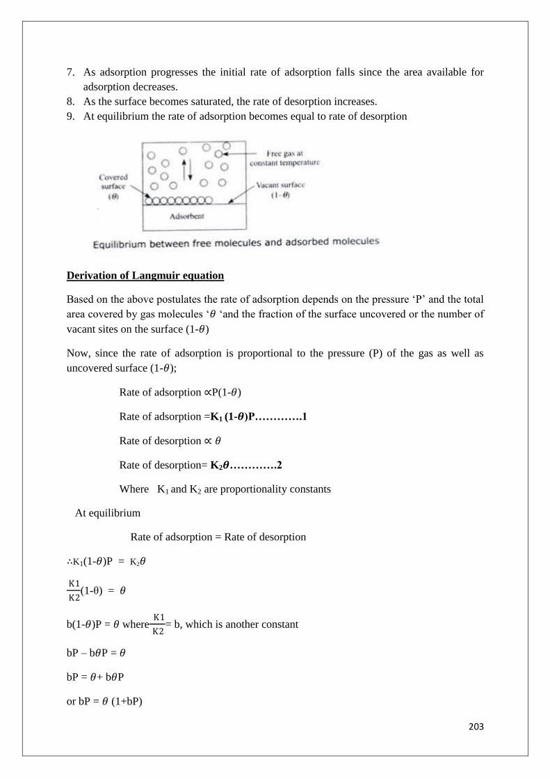
203
7. As adsorption progresses the initial rate of adsorption falls since the area available for
adsorption decreases.
8. As the surface becomes saturated, the rate of desorption increases.
9. At equilibrium the rate of adsorption becomes equal to rate of desorption
Derivation of Langmuir equation
Based on the above postulates the rate of adsorption depends on the pressure „P‟ and the total
area covered by gas molecules „𝜃 „and the fraction of the surface uncovered or the number of
vacant sites on the surface (1-𝜃)
Now, since the rate of adsorption is proportional to the pressure (P) of the gas as well as
uncovered surface (1-𝜃);
Rate of adsorption ∝P(1-𝜃)
Rate of adsorption =K1 (1-𝜽)P………….1
Rate of desorption ∝ 𝜃
Rate of desorption= K2𝜽………….2
Where K1 and K2 are proportionality constants
At equilibrium
Rate of adsorption = Rate of desorption
∴K1(1-𝜃)P = K2𝜃
K1
K2(1-θ) = 𝜃
b(1-𝜃)P = 𝜃 where K1
K2= b, which is another constant
bP – b𝜃P = 𝜃
bP = 𝜃+ b𝜃P
or bP = 𝜃 (1+bP)

204
∴𝑏𝑃
1+𝑏𝑃= 𝜃……………….. (1)
Since, the adsorbed gas molecules form unimolecular layer, the amount of gas adsorbed per
unit mass of adsorbent must be proportional to the fraction of the surface covered, i.e.,
∴x/m∝ 𝜃
x/m = K𝜃
x/m = K.𝑏𝑃
1+𝑏𝑃
x/m = 𝑎 .𝑃
1+𝑏𝑃 …………..(2) (a = Kb)
Verification of Langmuir adsorption isotherm:
Dividing eq (2) by P, then
𝑥/𝑚
𝑃=
𝑎.𝑃
1 + 𝑏𝑃.1
𝑃
𝑥/𝑚
𝑃=
𝑎
1+𝑏𝑃 ……….. (3)
Taking reciprocal of eq (3), we have
𝑃
𝑥/𝑚=
1 + 𝑏𝑃
𝑎
or𝑃
𝑥/𝑚 =
1
𝑎 +𝑏
𝑎P
Since a and b are constants, a plot of P/x/m against P should give a straight line with slope
equal to b/a and intercept on y-axis is equal to 1/a

205
Advantages of Langmuir theory:
1. Langmuir explained chemisorption
2. This theory is more satisfactory than Freundlich, while explaining physical adsorption
of gases on different adsorbents when saturation is approached
Limitations
1. According to Langmuir, adsorption is independent of temperature, but it actually
decreases with temperature
2. It explains theory of unimolecular adsorption
APPLICATIONS OF ADSORPTION
1. Activated charcoal is used in gas masks in which all undesirable toxic gases are adsorbed
selectively by charcoal; while purified air passes through its pores.
2. Activated charcoal is used removing coloring matter of sugar solution and the
decoloration of vinegar.
3. Silica and alumina gels are used as adsorbent for removing moisture and for controlling
humidity of room. Silica gel has been employed for drying air, used in blast furnaces.
4. Charcoal adsorption filters are used for removing organic matter from drinking water.
5. Selective adsorption by alumina, magnesia, etc., has been used for separating different
pigments by adsorption chromatography.
6. During arsenic poisoning, colloidal ferric hydroxide is administered. The latter adsorbs
the arsenic poison and retains it and can thus be removed from the body by vomiting.
7. Fuller‟s earth is used in large quantities for refining petroleum and vegetable oils, due to
its good adsorption capacity for unwanted materials.
8. The phenomenon of adsorption is useful in heterogeneous catalysis, e.g., finely divided
iron in the manufacture of ammonia and Ni in the hydrogenation of oil.
9. In Permutit (Zeolite) process, the Permutit adsorbs Ca2+
and Mg2+
ions in hard water and
thus water coming out of Permutit is free from Ca2+
and Mg2+
ions
10. Mordant (like alum) used in dying cloth, adsorb the dye particles, which otherwise do not
stick to the cloth.
11. Adsorption plays an important role in chromatographic analysis. Mixtures of small
quantities of organic substances can be separated by chromatography based on the
principle of adsorption
COLLOIDAL CHEMISTRY:
Thomas Graham (1861), classified all the soluble substances into two classes: “crystalloids”
and “colloids” on the basis of their ability of diffusion through vegetable or animal membrane
1. Crystalloids, which diffuse readily in solution and whose solution can readily pass
through animal or vegetable membranes, e.g., urea, sugar, salts, acids, bases and other
crystalline substances.

206
2. Colloids (from the Greek words kollaand eidos, which means glue and like respectively),
which diffuse very slowly in solution and whose solution cannot pass through animal or
vegetable membranes, e.g; starch, glue, albumin, gelatin, silicic acid, proteins and other
amorphous substances.
In recent years, Graham‟s view about the classification of substances has undergone a great
change, because it has been shown that every substance, irrespective of its nature, can be
colloid under suitable conditions. Thus, we now talk of colloidal state, which may be defined
as follows: A substance is said to be in the colloidal state, when it is dispersed in another
medium in the form of very small particles having diameter of 2x10⁻⁴
to 1x10⁻⁷
cm.
Types of solutions: On the basis of size of particle dispersed size, the solutions may be
following three types:
1. True solution is a “homogenous” solution containing dispersed particles of molecular
size (i.e., less than 10 A° or 1 nm), e.g., sodium chloride or glucose solution in water. The
particles of solute(molecules/ions) are invisible even under ultramicroscope and can pass
through an ordinary filter paper as well as animal/vegetable membrane.
2. Suspension is a “heterogeneous” mixture containing suspended insoluble particles of
size greater than1000 A° or 100 nm. The particles of a suspension cannot pass through an
ordinary filter paper as well as animal/vegetable membrane. The particles may be visible
even to the naked eye, but are visible under a microscope.
3. Colloidal solution is a “heterogeneous” two phase system, in which a substance is
distributed in colloidal state (i.e., of diameter 2x10⁻⁴
to 1x10⁻⁷
cm) in an insoluble medium.
The particles of the dispersed substance in internal or discontinuous phase, are called
dispersed phase; while insoluble medium or external phase, in which they are dispersed, it is
called dispersion medium. Besides these, a colloidal solution may also contain a stabilizing
agent – a substance which tends to keep the colloidal particles apart thereby avoiding their
coalescence and consequent settling.
Eg: NaCl in water acts as crystalloid but in benzene it acts as colloid
Similarly soap acts as a colloid in water and crystalloid in alcohol
Phases of Colloidal Solution
A colloidal solution is a heterogeneous system and consists of two phases. They are dispersed
phase and dispersion medium
Dispersed Phase:The phase which is present in the form of extremely small particles
dispersed in a solvent is called “dispersed phase.” It is also called internal or discontinuous
phase.
Eg. In the colloidal solution of starch in water, starch acts as dispersed phase

207
Smoke is a colloidal solution of carbon particles in air, here carbon particles act as
dispersed phase
Dispersion medium: The medium in which the colloidal particles are dispersed is called
“dispersion medium”. It is also called external or continuous phase.
Eg: In the colloidal solution of starch in water, water acts as dispersion medium
Smoke is a colloidal suspension of carbon particles in the air, air acts as dispersion medium
Classification of colloidal Solutions:
2. Base on the state of aggregation of two phases
Dispersion
Phase
Dispersion
medium
Colloidal
system
Examples
Solid Solid Solid sols Gems, ruby glass, minerals, alloys
Solid Liquid Colloidal sol Gold sol, Fe(OH)3 sol
Solid Gas Solid Aerosol Smoke, Haze(dust in air)
Liquid Solid Gels Jellies, curd, cheese
Liquid Liquid Emulsions Milk, cream, oil in water
Liquid Gas Liquid Aerosols Fog, Mist, cloud
Gas Solid Solid foam Foam rubber, pumic stone
Gas Liquid Foam Soap lather, lemonade froth soda
water
3. Base on the nature of Dispersion medium:
1. The colloidal system is known as sol, when the dispersion medium is liquid
2. When the dispersion medium is gas, then the colloidal system is known as Aerosol
3. When the dispersion medium is water, then the colloidal system is known as hydrosol.
4. If the dispersion medium is alcohol, it is called alcohosol. If the dispersion medium is
benzene, it is called benzosol
4. Based on the affinity of Dispersed phase for Dispersion medium
Depending upon the interaction between the dispersed phase and the dispersion medium, the
colloidal solutions are classified into two types
a) Lyophilic sols or solvent – loving sols
b) Lyophobic sols or solvent – hating sols.
Lyophilic Sols: (lyo-solvent, philic-loving)
The colloidal solutions in which the particles of dispersed phase have great affinity for the
dispersion medium are called “Lyophilic sols
Examples: Starch, gelatin, albumin, glue, and agar sols in water.

208
Characteristics:
They have tendency to pass directly into colloidal sol from, when dispersed phase is
brought in contact with the dispersion medium.
They are quite stable sols.
They are reversible sols, i.e., solid residue of a lyophilic sol (obtained by evaporation) can
be brought back to the sol form by merely shaking it with the dispersion medium.
They are self-stabilized, due to the existence of strong attractive forces between the two
phases.
They are not easily precipitated by addition of electrolytes.
The affinity of colloidal particles for the medium is due to hydrogen bonding with water
Lyophobic sols (lyo-solvent, phobic-hating)
The colloidal solutions in which the dispersed phase has no affinity for the dispersion
medium are called “Lyophobic sols”.
Examples: Gold sol, silver sol, and arsenic sulphide sol in water
Characteristics:
They cannot be prepared by bringing the dispersed phase in direct contact with dispersion
medium. They are formed by substances like As2S3, Fe(OH)3 sol, gold and other metals
which are sparingly soluble.
They are irreversible sols, since on evaporating the dispersion medium (water), the
residue can not readily be reconverted into sol.
They are comparatively much less stable, and are coagulated (or precipitated) more easily
by addition of even a little electrolyte.
Their surface tension is almost identical to that of dispersion medium.
For their stability, addition of stabilizer is essential.
Characteristics of Lyophilic and Lyophobic Sols
Property Lyophilic sols Lyophobic sols
Ease of
preparation
Formed easily by mere shaking or
warming the disperse phase in the
dispersion medium (i.e., solvent). No
stabilizer is needed to preserve them.
They are difficult to prepare. They
are formed only by special
methods. Addition of stabilizer is
essential for their stability.
Nature of
particles
Particles are solvent-loving and in the
form of single molecules
Particles are solvent-hating and
consist of aggregates of large
number of associated molecules.
Solvation Highly solvated Less solvated

209
Surface tension Surface tension is generally, lower than
that of the medium itself.
Surface tension is almost the same
as that of dispersion medium
Viscosity Viscosity is higher than that of solvent Viscosity is about the same as that
of medium.
Visibility under
ultramicroscoe
The particles cannot be detected readily,
even under ultra microscope, since they
are highly solvated
The particles can be readily
detected under ultra microscope
Charge on
particles
The charge on the particles depends
upon the pH of the medium and it may
be +ve, or -ve or even neutral.
The particles have a characteristic
either +ve charge, or –ve charge
e.g., As2S3 sol particles possess
–ve charge
Tyndall effect Due to small particle size, they do not
scatter light and hence they show very
weak Tyndall effect
Particles are large enough to
exhibit Tyndall effect
Migration in
the electric
field
The particles may migrate in either
direction or even not at all, under the
influence of an electric field.
The particles move in definite
direction, i.e., either towards anode
or cathode, depending on the type
of their charge.
Stability Very stable Less stable
Action of
electrolyte
Coagulation can be brought about only
by the addition of large quantities of
electrolytes.
The addition of even small
quantity of electrolyte can cause
coagulation.
Reversibility Reversible Irreversible
Example Gelatin sol in water As2S3 or Au sol in water
Optical properties -Tyndall effect:
If a powerful beam of light is passed through a colloidal solution(contained in a glass cell),
placed in a dark room, the path of the beam becomes visible, when viewed through a
microscope placed at right angles to the path of light. The colloidal particles appear as pin-
points of light moving against the dark background. This phenomenon is known as Tyndall
effect and the microscope with a dark background, used for viewing the colloidal particles, is
called ultra microscope. Cause of Tyndall effect is believed to be due to scattering of light by
the colloidal particles. The colloidal particles absorb the incident light energy, become self-
luminous and scatter this absorbed light from their surfaces. As the intensity of scattering is
maximum in the plane at right angles to the direction of incident beam, so the path becomes
visible, when viewed from the sides. The molecules constituting a true solution do not scatter
light, as their size is comparatively very small.

210
The colloidal particles appear as bright spots against a dark background in an area resembling
a cone. This area in which the colloidal particles are visible under microscope is called
Tyndall cone.
The appearance of dust particles in a semi-darkened room when a sun beam enters or when a
light is thrown from a projector in cinema hall are well known examples of Tyndall effect.
The dust particles are large enough to scatter light which makes the path of light visible
Conditions for the system to show Tyndall effect:
1. The diameter of particles of the dispersed phase must not be much smaller than the
wavelength of light used
2. The intensity of the scattered light depends on the difference between the refractive
indices of the dispersed phase and the dispersion medium. In lyophobic sols, the
difference is appreciable and therefore the Tyndall effect is quite well defined. But in
lyophilic sols, the particles are largely solvated and this lowers the differences in the
refractive indices of two phases and hence the Tyndall effect is much weaker
Origin of charge on colloidal particles
For any given colloidal system, the charge present on it is considered to be neutral. This is
because, the dispersed phase and dispersion medium in a colloidal system carry equal and
opposite charges. As a result the colloidal system as a whole appears as neutral
The origin of charge on colloidal particles is mainly due to:
1. Adsorption of ions from dispersion medium
2. Self dissociation or ionization of surface groups
Adsorption of ions from dispersion medium
Colloidal particles acquire charge as a result of adsorption of ions of electrolyte
during the method of preparation. The charge on colloidal particles is due to preferential
adsorption of either positive or negative ions on their surface. If the particles have a
preference to adsorb positive ion, they acquire positive charge and if they prefer to adsorb
negative ions, they acquire a negative charge

211
Example:
1. The positive charge on ferrichydroxide sol prepared by hydrolysis of FeCl3 is due to
preferential adsorption of common ion Fe3+
from the aqueous medium. The ferric ions come
from the ionization of ferric chloride
2. In the preparation of arsenic sulphide (As2S3) sol, the particles adsorb sulphide ions
which are negative and hence it is negatively charged. The sulphide ions are furnished by
ionization of H2S
As the dispersion medium and dispersed phase carry equal and opposite charges a double
layer is formed at the surface of colloidal particles. The theory of electrical double layer was
proposed by Helmholtz
The ions adsorbed by the colloidal particles forms fixed part of the double layer and the ions
present in the medium forms diffused layer of the electrical double layer
Due to the existence of charges on fixed layer and diffused layer a potential difference exists
between the two layers known as zeta potential or electro kinetic potential

212
Electrical properties of colloids:
Electrokinetic effect: In any colloidal system both dispersed phase and dispersion medium
are having equal and opposite charges. So when electric field is applied, the dispersed phase
and dispersion medium move in opposite directions. This effect is known as electrokinetic
effect.
If by applying electric field, only dispersed phase is moving then the process is known as
Electrophoresis.
On the other hand, if dispersion medium is moving, then the process is known as Electro-
osmosis. Both the processes are used to determine the charge on colloidal particles.
Electrophoresis:
When a colloidal solution is subjected to the influence of an electric field, the colloidal
particles move to one of the electrode. This movement is called Electrophoresis.
Silver sol, Gold sol, Arsenic sulphide sol move towards the anode. Therefore these colloidal
particles are positively charged. This phenomenon of movement of colloidal particles towards
anode is called”Anaphoresis”.
But Fe(OH)3 sol is positively charged. Hence it moves towards the cathode. This
phenomenon of movement of colloidal particles towards cathode is called “Cataphoresis”
The apparatus is a U-tube filled with small amount of water and the rest of the tube is filled
with colloidal solution. Two Pt electrodes are dipped in water. If electric current is applied
across the electrodes, the dispersed particles move towards one or the other electrodes. If sol
particles move towards anode, then the sol level rises on the anode side and falls on the
cathode side. This movement of the particles towards +ve electrode (anode) shows the charge
on particle is negative

213
Electro-osmosis:
When an electric current is passed through colloidal solution in such a way that the dispersed
particles are prevented from movement, it is observed that the dispersion medium moves.
This phenomenon of movement of the dispersion medium of a colloidal solution, under the
influence of an electric field, when the dispersed particles are prevented from moving, is
known as electro-osmosis.
The sol is placed in the central compartment A, separated from compartments B and
C by dialyzing membranes M and M1. The two compartments and their corresponding side
tubes T and T1 are filled with water. When a potential difference is applied across the two
electrodes placed close to the membranes M and M1 in compartments B and C, water
beginning to rise on one of the side tube and falls in the other depending upon the charge of
the sol placed in the compartment A. Ex: If the sol particles carry +ve charge, the medium
(i.e) water will cary –ve charge and hence it will move towards the anode with the result the
level of water in the side tube „T‟ will rise and that of T1 fall.
Electro-osmosis may be calculated using the formula P = hdg
Where P = Pressure, h = difference in water level, d = density of the particles, g =
acceleration due to gravity
Kinetic property-Brownian movement:
The molecules of dispersion medium are in a constant motion. These molecules keep on
bombarding thecolloidal particles. Occasional difference of impact forces causes a translator
motion to the colloidal particles.These colloidal particles keep on moving in straight line until
they encounter other collisions. Because of thefrequent collisions, there is no preference of
direction, direction changes with every collision. Thus, colloidalparticles execute continuous,
zigzag and random motion. This phenomenon was first noticed by Robert Brown(an English
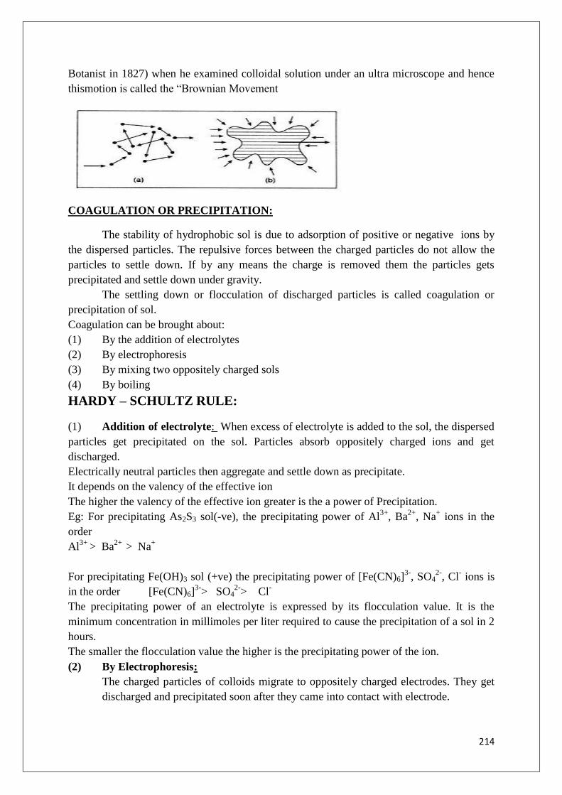
214
Botanist in 1827) when he examined colloidal solution under an ultra microscope and hence
thismotion is called the “Brownian Movement
COAGULATION OR PRECIPITATION:
The stability of hydrophobic sol is due to adsorption of positive or negative ions by
the dispersed particles. The repulsive forces between the charged particles do not allow the
particles to settle down. If by any means the charge is removed them the particles gets
precipitated and settle down under gravity.
The settling down or flocculation of discharged particles is called coagulation or
precipitation of sol.
Coagulation can be brought about:
(1) By the addition of electrolytes
(2) By electrophoresis
(3) By mixing two oppositely charged sols
(4) By boiling
HARDY – SCHULTZ RULE:
(1) Addition of electrolyte: When excess of electrolyte is added to the sol, the dispersed
particles get precipitated on the sol. Particles absorb oppositely charged ions and get
discharged.
Electrically neutral particles then aggregate and settle down as precipitate.
It depends on the valency of the effective ion
The higher the valency of the effective ion greater is the a power of Precipitation.
Eg: For precipitating As2S3 sol(-ve), the precipitating power of Al3+
, Ba2+
, Na+ ions in the
order
Al3+
> Ba2+
> Na+
For precipitating Fe(OH)3 sol (+ve) the precipitating power of [Fe(CN)6]3-
, SO42-
, Cl- ions is
in the order [Fe(CN)6]3-
> SO42-
> Cl-
The precipitating power of an electrolyte is expressed by its flocculation value. It is the
minimum concentration in millimoles per liter required to cause the precipitation of a sol in 2
hours.
The smaller the flocculation value the higher is the precipitating power of the ion.
(2) By Electrophoresis:
The charged particles of colloids migrate to oppositely charged electrodes. They get
discharged and precipitated soon after they came into contact with electrode.

215
(3) By mixing oppositely charged sol:
Positive particles of sols are attracted by negative particles of second sol. Mutual
adsorption and precipitation of both the sols occurs.
(4) By Boiling:
On boiling, the collision between sol particles and water molecules removes adsorbed
layer, charges from particles are taken away and precipitation occur.
Protection of Colloids/Stability of Colloids (Gold Number)
Lyophilic colloids are stable and reversible. The stability depends on the degree of hydration.
They achieve extraordinary stability due to solvation of colloidal particles.
Lyophobic sols are easily precipitated when small amount of electrolyte is added. The
property of lyophilic sols to prevent precipitation of a lyophobic sol is called protection. The
lyophilic sol used to protect a lyophobic sol from precipitation is known as protective colloid.
Eg: Lyophilic colloids such as gelatin, starch etc, acts as a protective colloid for Gold sol and
prevent their precipitation by the addition of limited amount of NaCl. It is because the
particles of lyophobic sol adsorb the particles of lyophilic sol, and lyophilic colloid forms a
protective cover around lyophobic sol
Gold Number
The protective power of lyophilic sol is expressed in terms of “Gold Number”.
Gold number is defined as the number of milligrams of a lyophilic colloid that prevent the
precipitation of 10 ml of gold sol on addition of 10% NaCl solution.
The smaller the gold number, the greater is the protective action of lyophilic colloid
If a protective colloid is having more gold number it indicates that it is having less
protective power
Both gold number and protective power are inversely proportional to each other
Lyophilic colloid Gold number
Gelatin
Heamoglobin
Gum-Arabic
Potato starch
0.005-0.01
0.03-0.07
0.1-0.15
15-25
Gelatin is having maximum protective nature as it is having less gold number.
Starch is having minimum protective nature as it‟s gold number is high.
Gelatin is a very effective protective colloid
Gold number∝ 1/Protective nature

216
Micelles:
Colloidal molecules can cluster together simultaneously at reasonably high concentration to
from thermodynamically stable bigger particles of colloidal dimension, called as association
colloids. These associated colloids may be called as „micelles‟. These molecules at lower
concentration behave as strong electrolytes. In concentrated solutions, these substances
exhibit particles of colloidal size. Therefore the colloidal size aggregates of soap or detergent
molecules formed in a concentrated solution are referred to as micelles. The number of
micelles decreases with dilution since the ionic micelles dissociates into individual ions on
dilution. Therefore the minimum concentration at which the micelle formation starts is
designated as the critical micellisation concentration. Hence micelles are stable above critical
micellisation and below they dissociate into individual ions.
Some of the substance which form micelles in concentrated solutions are:
i) Sodium stearate (soap): C17H35COO-Na
+
C17H35COO-Na
+ C17H35COO
- + Na
+
Sodium stearate stearate ion
As many as 70 stearate ions aggregate to form a micelle of colloidal size. The stearate ion has
a long hydrocarbon chain with a polar-coo- group at one end. The zigzag hydrocarbon tail is
shown by a wavy line and the polar head by a hollow circle. In the micelle formation, the tails
being insoluble in water are directed towards the center, while the soluble polar heads are on
the surface in contact with water. The charge on the micelle is due to the polar heads
whichaccounts for the stability of the particles.
Applications of Colloids
In everyday life: Colloids play an important role in our daily life. Protoplasm (out of which
the plant cells and animal tissues are made) and blood (which flows through our veins) are all
colloidal in character. The food (milk, butter, cheese, fruits, etc.) that we eat, the clothes and

217
shoes that we wear are based on colloids. In fact, there is hardly any product that we use in
everyday life, which does not depend on colloids.
Analytical Applications:
A knowledge of the behavior of colloids and their mode of formation plays an important role
in analytical chemistry.
1. Identification of traces of noble metals: The traces of the noble metals are identified by
the colloidal nature of some metals. When noble metal is present in colloidal form they
produce very bright and intense colors. For example, the cassius purple test for gold is due to
the production of colloidal gold.
2. Detecting the natural honey from artificial honey: The distinction between natural and
artificial honey is made by Leys‟ test. A few drops of honey are mixed with ammonical silver
nitrate solution. In the case of pure and natural honey the metallic silver acquires the reddish
yellow colour due to the albumin or ethereal oils. A greenish precipitate is obtained with
artificial honey.
3. Qualitative and quantitative analysis:
(i) Colloidal S, obtained by passing H2S in qualitative analysis, cannot be ordinarily filtered
off, but it is coagulated by heating with the electrolyte like NH4NO3 or NH4Cl.
(iii) Silica and alumina gels are used as adsorbent for gases and as drying agents in
laboratory.
In gravimetric analysis of BaSO4, a little HCl is added before adding the
precipitating agent.This is to avoid the colloidal formation during analysis.
In volumetric analysis hydrophilic colloids alter the end point i.e. in the titration of
HCl and NaOH, the duration of end point is increased with increasing amount of
colloid.
In medicine:Because of their easy assimilation and adsorption, the colloidal medicines are
found to be much more effective, e.g.
(i) argyrols and protargrol are colloidal sols of Ag and used as eye-lotions
(ii)colloidal gold, calcium and iron are used as oral medicines as well as injectables for
raising the vitality of human system
(iii) colloidal antimony is an effective medicine for Kalazar
(iv) Blood from minor wounds, cuts is stopped, by coagulation with alum or ferric chloride.
The trivalent Al3+
or Fe3+
ions neutralize the negative charge on the albuminoid
particles,whichconstitute the blood, and thus coagulate it.
In industry:
(a) Electrophoresis has been utilized in the following:
(i) Smoke precipitation:
In big industrial cities, smoke is a nuisance, as it pollutes the atmosphere as well as injurious
to health. Smoke is a negatively charged colloidal solution, consisting of carbon particles

218
dispersed in air. For the precipitation of carbon particles of the smoke, it is passed through a
chamber, provided with a highly positively charged metallic knob. The negatively charged
smoke (or carbon)particles, on coming in contact with the knob, lose their charge and settle
down on the floor of the chamber; while hot gases (free from the smoke) passes out through
the chimney. The precipitated carbon is used as a by-product for making Indian ink, paints,
etc.
(ii) Removal of dirt from sewage:
The sewage of the towns consists of charged dirt particles dispersed in water. For effecting
separation of dirt particles, sewage is passed through a system of two tanks, fitted with
oppositely charged metallic electrodes. The suspended dirt particles get coagulated and
deposited on the oppositely charged electrodes. The deposited dirt is the used as good
manure.
(iii)Purification of water:
When alum is added to impure water containing suspended negatively charged clay particles,
bacterial, etc., the Al3+
ions (furnished by alum) brings about precipitation of negatively
charged colloidal impurities; while the clear water is decanted off.
(iv)Electroplating of rubber:
Latex (obtained from saps of certain trees, from which rubber is made) is a colloidal
suspension of negatively charged rubber particles in water. Metals and wooden articles can be
rubber- plated by making them anode in the electrophoresis of latex, when the negatively
charged rubber particles get deposited on the articles.
(v) Leather tanning
Tanning of leather is based on the mutual coagulation of oppositely charged colloids. The
raw animal skin is positively charged colloidal system, consisting of proteins in the colloidal
form. The extract of barks, wood, leaves, etc., is a negatively charged colloidal solution of
tannin. When the two are mixed, inadequate proportions, mutual coagulation of two
oppositely charged sols takes place and the surface of leather becomes hard, which does not
putrefy easily.
In laundry:
Cleaning action of Soap: Most of the dirt or dust sticks on greasy or oily materials which
somehow gather on cloth. As grease is not readily wetted by water, it is difficult to clean the
garment by water alone. The cleaning action of soap may be explained as:
(a) Soap, etc., used for washing, yields a colloidal solution in water, which removes the dirt
of the cotton, etc., by adsorption of greasy materials by emulsion formation.
(b) It lowers the interfacial tension between water and grease and this causes the
emulsification of grease in water. The mechanical action such as rubbing, releases the
dirt.

219
Artificial rains
Artificial rainshave been obtained by throwing electrically charged sand into clouds.
In warfare
Animal charcoal is used in gas masks for adsorption of poisonous gases. Smoke screens, used
in warfare, consist of colloidal titanium oxide particles dispersed in air.
In nature:
i) Blue color of the sky:Sun light falling on the earth is partially reflected back by
the earth‟s surface. On its way back this light hits the dust particles present in the
atmosphere. The colloidal particles of dust are quite small and are capable of
reflecting only blue radiation while the radiations of other colors escape through
the sky and therefore the sky looks bluish. If there was no such scattering, the sky
would have appeared totally dark. Sea water is also blue in colour due to
scattering of light by impurities present in sea water.
ii) Rain: Cloud consists of water particles dispersed in air. As the air reaches to a
cool region the condensation in the form of tiny drops occurs. Further cooling and
condensation forms bigger drops which fall down under the action of gravity in
the form of rain.
iii) Tail of comets: Comets are celestial bodies moving at tremendous speed.During
their motion they leave behind tiny solid particles suspended in air. The light
falling on them is scattered leaving a Tyndall cone like structure which we call as
tail of comets.
iv) Formation of Delta: When river water meets the sea water, some sand is
collected at the point of their meet. This is known as delta. Formation of delta can
be explained as follows; the river water is colloidal suspension of clay or sand in
water. Sea water contains a number of electrolytes dissolved in it, so when sea
water comes in contact with sea water, the electrolytes present in sea water
coagulate the colloidal particles of clay or sand which deposit in the form of delta.
Top Related