


Languages
Pages
Legal


CH6701 CHEMICAL REACTION ENGINEERING – II
PART A
1.Define the following and give an example: Catalyst support and Promoter.(Nov/Dec 2017)
Catalyst support is the material, usually a solid with a high surface area, to which a catalyst is affixed.
The activityof heterogeneous catalysts and nanomaterial-based catalysts occurs at the surface atoms.
Consequently, great effort is made to maximize the surface area of a catalyst by distributing it over the
support. The support may be inert or participate in the catalytic reactions. Typical supports include
various kinds of carbon, alumina, and silica.
Catalyst promoters (or) activator are substances which do not act as catalyst but enhance the efficiency
or activity or selectivity or stability of catalyst and prolong catalyst life. For example, the catalytic
activity of V2O5 in oxidation of SO2 is enhanced appreciably when sulphates of alkali metals are added
in small amounts.
2. List the general characteristics of catalysts. (Nov/Dec 2017)
The important characteristics of a catalyst are:
(i) Activity
(ii) Kindling point
(iii) Specificity
(iv) Porous and crystalline structure of a catalyst.
Activity of a catalyst indicates its usefulness and is a measure of the accelerating effect it can have on the
rate of reaction. The choice of a catalyst is done on the basis of its activity.
Kindling point indicates the minimum temperature at which a catalytic process proceeds on a rate
sufficient for commercial operation. The catalyst needs to have low kindling point so that less energy is
required to preheat the reaction mixture.
Specificity also means selectivity of the catalyst. Specificity is a property of a catalyst and its indicates
its property to speed up the main reaction by suppressing other side reactions.
Porous structure is an important quality of the catalyst. A commercial catalyst needs to have an
extended external surface for maximum rate of reaction. Crystalline structure of the same catalyst
strongly reduces the catalyst activity. For example conversion of - Al2O3 to α - Al2O3 reduces its
activity by several orders of magnitude as a dehydrogenation catalyst.
UNIT I CATALYSTS
Nature of catalysts, surface area and pore-volume distribution, catalyst preparation.

3. What are the importance of pores in a catalyst particle?(Apr/May 2017) (or) Write about an
importance of surface area in catalyst. (Nov/Dec 2016)
(a)Porous structure is an important quality of the catalyst. A commercial catalyst needs to
have an extended external surface for maximum rate of reaction. Crystalline structure of the same
catalyst strongly reduces the catalyst activity. For example conversion of - Al2O3 to α - Al2O3
reduces its activity by several orders of magnitude as a dehydrogenation catalyst.
(b)The pores in a catalyst particle have a large surface area available for solid-fluid
interaction is highly useful in attaining a significant reaction rate.
(c)When the pores are considerably large and the gas is relatively dense or if the pores are
filled with liquid. If free cross section of the porous mass is θ, then diffusion flux per unit total cross
section of the porous catalyst is θ times the diffusion flux under similar conditions with no solid
present.
For Example,
(i)Alumina-silica cracking catalyst. It has a pore volume 0.6 cm3/gm. The average pore radius is
4nm. The corresponding surface area is around 300m2/gm.
(ii)Raney Nickel catalyst in the hydrogenation of vegetable and animal oils and platinum-on-alumina
catalyst in reforming of petroleum naptha to produce high octane rating are other good example of
porous and high surface area catalysts.
4. Differentiate micro and macro pore. (Nov/Dec 2016)
S.No. MICROPORE MACROPORE
1 Pores with diameter less than 2nm
(20 A0) are called micropores
Pores in the range of greater than 50 nm are called
macropores
5. What is bidispersed catalyst? (May/June 2016)
In some porous catalysts having macro-micro pore size distribution is seen.
It is called as bimodal pore size distribution.
Pelletized catalysts or extruded or porous carbon shows such bidispherse structure. In such cases,
mean pore radius re calculated by equation has very less significance. The micropore on have radius
as small as 23 – 25 A. The mean macropore radius can vary from 15000 A to 375 A as the catalyst
pellet density increases. Pellets with greater density show micropore diffusion characteristics. While
least density pellets show macropore diffusion characteristics.
6. Explain the crude way to find out pore volume of a porous catalyst.( Nov/Dec 2015)
(a) differential (b) cumulative

Pore size distribution can be represented both in differential and cumulative ways. The Fig. 4(a)
shows the differential BJH pore distribution of titania sample calcined at 4000C. The figure shows
that for the given sample pores were in the range of 2-10 nm. The corresponding cumulative pore
distribution is shown in Fig. 4(b).
(b) By mercury intrusion
For macropores materials with pore diameter greater than 50 nm, the mercury intrusion method is
preferred. Due to non-wetting nature of mercury on oxide supports, intrusion is met with resistance
and mercury is forced to enter the pores of material under pressure. The pore radius ‘r' is related to
the applied pressure P as
----------------------------(5)
The wetting or contact θ angle between mercury and solid is on average lies in the range 130-1400and surface
tension of mercury is 0.48 N/m2. p is in atm and r in nanometers.
7. Differentiate catalyst promoter and deactivator. ( Nov/Dec 2015) (Apr/May 2017)
S.No. CATALYST PROMOTER CATALYST DEACTIVATOR
1 Catalyst which increases the rate of a
reaction is a catalyst promoter
Catalyst which decreases the rate of a reaction is a
catalyst deactivator.
2 It is also called catalyst activator. It is also called catalyst inhibitor.
3 They can speed up slow reactions in a
sufficient manner to make them
commercially feasible.
They can slow down the fast reactions in a
sufficient manner to make them commercially
feasible.
4 For example,
In the catalytic activity of V2O5 in
oxidation of SO2 is enhanced
appreciably when sulphates of alkali
metals are added in small amounts.
For example,
In the oxidation of ethylene, ethylene oxide is the
desirable product. At the same conditions CO2 and
H2O are also formed by complete oxidation, but
this reaction is undesirable and needs to be
suppressed. In this process silver supported alumina
is a good catalyst but if halogen compound is
added, CO2 and H2O formation is reduced.
8.What are promoters and inhibitors? (NOV/DEC 2014) (Apr/May 2016)
Catalyst promoters (or) activator are substances which do not act as catalyst but enhance the
efficiency or activity or selectivity or stability of catalyst and prolong catalyst life. For example, the catalytic

activity of V2O5 in oxidation of SO2 is enhanced appreciably when sulphates of alkali metals are added in
small amounts.
Catalyst inhibitors(or) deactivators are substances which decrease the rate of reaction, or activity or
selectivity or stability of the catalyst. For example in the oxidation of ethylene, ethylene oxide is the
desirable product. At the same conditions CO2 and H2O are also formed by complete oxidation, but this
reaction is undesirable and needs to be suppressed. In this process silver supported alumina is a good catalyst
but if halogen compound is added, CO2 and H2O formation is reduced.
9. What is meant by catalyst?
A Catalyst is a substance that alters the rate of reaction, but remains unchanged after the
reaction. Many chemical reactions which are not feasible under normal conditions can be carried out
in the presence of catalyst.
10. What are the characteristics of catalyst in catalytic reactions?
(i) Catalyst remains unchanged at the end of reaction.
(ii) Very small quantity of catalyst is sufficient to enhance the rate of reaction.
(iii) Catalyst activates the molecules and reduces the activation energy necessary for a chemical
reaction to occur.
(iv) Catalyst develops new mechanism for a reaction.
(v) Catalyst does not alter the chemical equilibrium.
(vi) The activation energy of a catalyzed reaction is comparatively less as compared to non
catalyzed reaction.
(vii) Catalysts plays a specific role in chemical reaction. Therefore a good catalyst for one
reaction may be totally ineffective in other reaction.
(viii) Catalyst can reduce the cost of production.
(ix) Catalyst can affect yield and selectivity of a chemical reaction because of its ability to
change the reaction mechanism.
11. Define Effectiveness Factor of a catalyst. (May 2015).
Effectiveness Factor of a catalyst can be defined as:
Effectiveness factor = Actual mean reaction rate within pore /Rate if not slowed by pore diffusion.
12. What is meant by catalyst Deactivation?
Activity of catalysts normally decreases with time.
During the course of operation, the activity of catalyst gets reduced and it is not able to provide
expected performance. The catalyst needs to be reactivated. Catalyst deactivation may be caused by
ageing phenomena. Catalyst deactivation may be very fast. The life of any catalyst generally depends

on type of reactions as well as reaction conditions.
For example, catalysts for catalytic cracking lose much of their activity within seconds due to carbon
deposition on the surface and carbon has blocked catalyst pores while promoted iron catalysts used
in ammonia synthesis have a lifetime of years
13. What are types of catalyst Deactivation? (May 2012).
Catalyst Deactivation can be divided into following three categories:
(i) Deactivation by sintering (also called as ageing),
(ii) Deactivation by fouling or coking
(iii) Deactivation by poisoning.
14. Name the methods of preparing solid catalyst.
1. Bulk preparation method.
2. Impregnation method
3. Physical mixing of components
15. Name the three categories of Industrial catalysts.
1. Bulk catalysts.
2. Supported catalyst.
3. Mixed Agglomerates.
16. How will represent pore-volume distribution?
Pore size distribution can be represented both in differential and cumulative ways.
17. Define Catalysis.
“Catalysis” is a term refers to a process in which the rate of reaction is influenced by a substance
(catalyst) that remains chemically unaffected.
18. What is homogeneous catalysis? Give one example.
Homogeneous catalysis is one in which the reactants, the catalyst and the products are in same or
single.
The basis for the any catalytic theory is that first the catalyst and one or more of the reactants form an
intermediate complex, a loosely bound compound – which is unstable. This complex then takes part
in subsequent reactions which results in the final products and the regenerated catalyst.
The kinetics of the hydrolysis of ethyl acetate catalyzed by hydrochloric acid can be explained by the
following mechanism.
CH3COOC2H5 + H+ → CH3C00C2H5 [H+]
CH3C00C2H5 [H+] + H2O → C2H5OH + CH3C00H + H+
19. Does a catalyst alter equilibrium conversion of a chemical reaction? Explain.
No. With a reversible reaction, a catalyst which increases the rate will increase the rate of both the
forward and the backward reaction. This is useful because the catalyst will, cause the reaction

mixture to reach its equilibrium composition more quickly. So, the catalyst will not change the
equilibrium composition of the substance and hence the conversion.
20. Is the selectivity of multiple reactions affected by catalysts? Explain.
Yes, the selectivity of multiple reactions is affected by catalysts. It means that the selectivity changes
only the rate of desired and undesired materials in the multiple reactions. Thus, in the presence of
appropriate catalyst, products containing predominantly the materials desired can be obtained from a
given feed.
21. Give the classification of catalyst.
There are two broad classes of catalyst;
Biochemical catalysts, called Enzymes, are found everywhere in the biochemical world and in
living creatures and operate at close to ambient temperature.
Man-made catalysts, mostly solids, usually aim to cause the high-temperature rupture or synthesis of
materials.
22. State the types of catalyst poisoning.
The decrease in the activity of catalyst due to poisons, which will be defined as substances (either in
the reactants stream or produced by reaction) which lower the activity of catalyst.
The types of catalyst poisoning are;
(i) Deposited poisons
(ii) Chemisorbed poisons
(iii)Selectivity poisons
(iv) Stability poisons
(v) Diffusion poisons
23. Define Effectiveness Factor of a catalyst. (May 2015).
Effectiveness Factor of a catalyst can be defined as:
Effectiveness factor = actual mean reaction rate within pore /rate if not slowed by pore diffusion.
24. What are types of catalyst deactivation? (May 2012).
Activity of catalysts normally decreases with time. The life of any catalyst generally depends on type
of reactions as well as reaction conditions. For example, catalysts for catalytic cracking lose much of
their activity within seconds due to carbon deposition on the surface while promoted iron catalysts
used in ammonia synthesis have a lifetime of years.
25. Name the components present in catalyst.
1. Catalytic agent
2. Support /carrier
3. Promoters and Inhibitors

26. Classify catalytic agents.
Catalytic agents may be broadly divided in the following categories:
Metallic conductors ( E.g Fe, Pt, Ag, etc.)
Semiconductors (E.g. NiO, ZnO, etc.)
Insulators (E.g. Al2O3, SiO2, etc.)
27. How will represent pore-volume distribution?
Pore size distribution can be represented both in differential and cumulative ways.
28. What are the carriers or support used and why they are used with catalyst?
A catalyst support is the material, usually a solid with a high surface area, to which a catalyst
is affixed. The reactivity of heterogeneous catalysts and nanomaterial-based catalysts occurs at the
surface atoms. Catalyst support results in highly porous nature - increase of available surface area
improve stability improves the heat transfer characteristics. Some of Alumina, Asbestos,
Carborundum, Iron oxide, Manganese, Activated carbon, Zinc oxide.
29. What is sol gel method of preparation of catalyst?
The sol-gel process is a wet-chemical technique (Chemical Solution Deposition) for the fabrication of
materials starting from a chemical solution that reacts to produce colloidal particles (sol).
Typical precursors are metal alkoxides and metal chlorides, which undergo hydrolysis and
polycondensation reactions to form a colloid, a system composed of solid particles (size ranging from
1 nm to 1 μm) dispersed in a solvent. The sol evolves then towards the formation of an inorganic
network containing a liquid phase (gel). Formation of a metal oxide involves connecting the metal
centers with oxo (M-O-M) or hydroxo (M-OH-M) bridges, therefore generating metal-oxo or metal-
hydroxo polymers in solution. The drying process serves to remove the liquid phase from the gel thus
forming a porous material, then a thermal treatment (firing) may be performed in order to favor
further polycondensation and enhance mechanical properties.
30. Which catalyst properties can be influenced by promoters?
Activity, selectivity and stability.
31. What is co-precipitation method of preparation of catalyst?
Catalyst based on more than one component can be prepared by co precipitation. According to
IUPAC nomenclature this term is used for the simultaneous precipitation of normal soluble
component with macro component from the same solution by the formation of mixed crystal by
adsorption, occlusion or by mechanical entrapment. Co-precipitation is very suitable for the
generation of homogeneous distribution of catalyst or for the creation of precursor of definite
stoichiometry which can be easily converted into active catalyst.
32. What is incipient wetness method of preparation of catalyst?

Incipient wetness impregnation is a commonly used technique for the synthesis of
heterogeneous catalysts. Typically, the active metal precursor is dissolved in an aqueous or
organic solution.
Then the metal-containing solution is added to a catalyst support containing the same pore
volume as the volume of solution that was added.
Capillary action draws the solution into the pores. The catalyst can then be dried and calcined to
drive off the volatile components within the solution, depositing the metal on the catalyst
surface
33. What are the main interactions that can occur between metals and support materials?
Electronic interactions; reduced support species on the metal surface; phase formation at interfacial
surfaces.
PART B
1) Discuss in detail the nature of catalyst and how it increases the rate of reaction.(Nov/Dec2015,
Apr/May 2017) (16 marks)
General characteristics of catalysts.
The important characteristics of a catalyst are:
(v) Activity
(vi) Kindling point
(vii) Specificity
(viii) Porous and crystalline structure of a catalyst.
Activity of a catalyst indicates its usefulness and is a measure of the accelerating effect it can
have on the rate of reaction. The choice of a catalyst is done on the basis of its activity.
Kindling point indicates the minimum temperature at which a catalytic process proceeds on a
rate sufficient for commercial operation. The catalyst needs to have low kindling point so that
less energy is required to preheat the reaction mixture.
Specificity also means selectivity of the catalyst. Specificity is a property of a catalyst and its
indicates its property to speed up the main reaction by suppressing other side reactions.
Porous structure is an important quality of the catalyst. A commercial catalyst needs to have an
extended external surface for maximum rate of reaction. Crystalline structure of the same
catalyst strongly reduces the catalyst activity. For example conversion of - Al2O3 to α - Al2O3
reduces its activity by several orders of magnitude as a dehydrogenation catalyst

2) Derive an expression for the critical pore radius of a catalyst. Also derive an equation to
estimate the average pore radius of a cylindrical pore of length ‘L’ and Radius ‘R’. (Nov/Dec
2017) (16 marks) (or)
Describe the method of finding (Nov/Dec2015)
(i) Surface area of catalyst. (8 marks)
(ii) Pore volume and pore volume distribution.(8 marks)
(i) Surface area of catalyst.
Surface area, pore size, pore volume determination
Determination of surface area and pore distribution of catalysts is important to understand the extent of
dispersion possible for the active metals. Higher surface area of support results in higher dispersion of the
active metals. Hence supports of higher surface area are desirable. Pores are usually formed during drying or
calcination of hydroxides precipitates or gel. The size and number of pores determines the internal surface
area. Pore size also determines the accessibility of reactants to the active sites and the ability of diffusion of
products back to the bulk fluid. Hence pore structure and surface area must be optimized to provide
maximum utilization of active sites for a given feed stock.
Working principle and instrumentation
The basic components of volumetric physical adsorption analyzer as shown in Fig. 1 are:
1) Analysis manifold of accurately known volume and temperature
2) Vacuum system with valve to manifold
3) Source of adsorptive gas (typically, N2) with valve to manifold
4) Pressure transducer and temperature sensor
5) Sample tube connected to analysis manifold
6) Liquid nitrogen bath
Determination of internal surface area is based on adsorption and condensation of N2 at liquid N2temperature,
77K. Initially, the sample is e vacuated at 293-523 K (120-250°C) followed by c ooling to 77 K by liquid N2.
Then gradually the partial pressure of nitrogen above the sample is increased. S ome quantity of gas will be
adsorbed by the sample and removed from the gas phase. After stabilization the equilibrated pressure is
recorded and a mount of nitrogen adsorbed at each equilibrated pressure is noted. The isotherm, volume
adsorbed as function of relative pressure p/po, is plotted from the data. The pressure over the sample is
gradually increased until pressure reaches near saturation pressure, by when the complete adsorption
isotherm is developed. The desorption isotherm is measured by a step-wise reduction in pressure until a low
pressure over the sample is achieved. Although the volumes are adsorbed at different conditions, the values

are reported at STP conditions. Fig. 2 shows a typical N2 adsorption and desorption isotherm at 77 K for
alumina.
Fig. 1. Basic components of volumetric physical adsorption analyzer
Fig. 2. A typical N2 adsorption and desorption isotherm at 77 K for alumina
Adsorption using Argon and Krypton
Krypton is used as adsorbate at 77 K for low surface area analysis while, Argon adsorption at 77 K and liquid
argon temperature (87K) is often used for micro and mesopores analysis.
To measure very low surface area the number of molecules trapped in the void volume of sample cell needs
to be reduced. The number of molecules left in void volume can be reduced by using adsorbate such as
Krypton with low vapor pressure at liquid nitrogen temperature. The saturation pressure of Krypton at liquid

nitrogen temperature is 0.35 kPa which is much lower compared to that of N2 (101.3 kPa). Consequently the
number of Krypton molecules in free space of sample cell, at any given relative pressure, is significantly
reduced compared to that of nitrogen at liquid nitrogen temperature, though amount of adsorption will be
only slightly less. Hence, Krypton adsorption at 77 K is much more sensitive and can be applied to measure
surface areas down to 0.05 m2. The cross sectional area used for Krypton is 0.202 nm2.
For analysis of ultramicropores less 0.7 nm, the nitrogen adsorption at 77 K is not satisfactory. The pore
width of 0.7 nm corresponds to bilayer thickness of nitrogen molecule. For ultramicropores, pore filling
occurs at relative pressure of 10-7 to 10-5, where the rate of diffusion and attainment of adsorption
equilibration is very slow. Consequently measurement becomes time consuming and may also cause non-
equilibrated adsorption isotherms with erroneous results. On the other hand argon fills the micropores of
dimension 0.4-0.8 nm in most cases at much higher relative pressure as compared to nitrogen. This leads to
accelerated diffusion and equilibration process and result in reduction of analysis time as well as increase in
accuracy. Argon adsorption is advantageous for pore size analysis of zeolites and other microporous
materials.
The typical surface area values of different supports and catalysts are summarized in Table 1.
Table 1. Typical surface area values of different support and catalyst.
Determination of surface area using BET Equation
As discussed earlier (lecture 4), the BET equation describes the relationship between volume adsorbed at a
given partial pressure and the volume adsorbed at monolayer coverage. BET equation can be written in the
form :
p = partial pressure of N2; p0 = saturation pressure at the experimental temperature;
v = volume adsorbed at p; vm = volume adsorbed at monolayer coverage; c = constant

Monolayer coverage is determined using BET equation. The is plotted as a function of .
The plot is linear in the range of relative pressures = 0.05 - 0.3. At higher relative pressure p/po, the BET
plot deviates from linearity as non-ideality or pore condensation was not accounted for the derivation of BET
equation.
Slope and intercept of this linear plot is used for determination of monolayer capacity vm.
The intercept and slope from the plot is given as
Then the monolayer volume vm is given as,
The total number of N2 molecules adsorbed corresponding to monolayer volume vm can be calculated as
Now each adsorbed N2 molecule occupies an area of surface comparable to its cross section area 0.162 nm2.
or
Pore size
(a) By gas adsorption
Pore size and pore size distribution can be determined using Kelvin equation. Kelvin equation relates
equilibrium vapor pressure (P) of a liquid contained in a capillary to equilibrium pressure of the same liquid
over a free surface (Po) :

At any equilibrium pressure, P, pore of radius less than ‘r' will be filled with the condensed vapor.
Application of Kelvin equation to all points of an isotherm at relative pressure greater than that
corresponding to monolayer volume where capillary condensation begins to occur, will yield information
concerning the volume of gas adsorbed in pores of different radii. For nitrogen as adsorbate and substituting
values of various constants the Kelvin equation can be written as
or -------------------------------(2)
The ‘rk' is the radius into which condensation occurs at the required relative pressure. This radius is called
Kelvin radius. However, Kelvin radius is not the actual pore radius since some adsorption has already
occurred on the pore wall prior to condensation leaving a central core of radius rk. Conversely an adsorbed
film remains on the wall when evaporation of the centre core takes place.
Fig. 3. Schematic showing Kelvin radius and actual pore radius during pore condensation
Then if ‘r' is the actual pore radius and the thickness of the adsorbed film is t ( Fig 4) then
---------------------------------(3)
Pore size distribution can be obtained by the analysis of either adsorption or desorption isotherm branches.
Kelvin equations as described is applied to the desorption branch of hysteresis loop as it is more appropriates
to assign wetting angle to a pore filled with liquid that possess a well defined meniscus. If ‘ h ' is the effective
height of a monolayer then thickness of adsorbed layer ‘ t ' is given as . Here ‘V' is the volume of

gas adsorbed and ‘Vm' is the volume of adsorbed monolayer. When the packing of adsorbate is in hexagonal
mode then for nitrogen h = 3.6A0 and for cubic packing h= 4.3 A0 = 0.43 nm . The ‘t ' at a given relative
pressure can also be calculated using Halsey equation
-----------------------------(4)
Pore size distribution
Most common method for determination of pore size distribution is BJH (Barrett-Joyner-Halenda) method.
Assumptions are:
(i) Condensation occurs in pores when a critical relative pressure is reached corresponding to the Kelvin
radius ‘rk'
(ii) When evaporation or condensation occurs, a multilayer of adsorbed film exist on the pore wall and this
film has same depth/thickness as the adsorbed film on a non porous surface
(iii) Actual pore volume evaporation is composed of the volume evaporated out of the central core plus the
volume desorbed from the film left on the pore walls
Steps in for determination of pore size distribution are as follows:
1. P/P0 and Vgas (STP, cm3/g) data obtained directly from isotherm
2. Then Kelvin radius ‘rk' is calculated from Kelvin equation using zero wetting angle for N2 from
equation(2)
3. Then the film thickness t calculated from Halsey equation(4) at each P/P0
4. Then the pore radius rp calculated from equation (3)
5. Mean values of rk and rp in each decrement are calculated from successive entries
6. Change in film thickness Δt is calculated from difference of successive values of t
7. Then ΔVgas, that is the change in adsorbed volume between successive P/P0 values, is determined by
subtracting successive values
8. Thereafter ΔVliq that is the volume of liquid corresponding to ΔVgas is calculated as follows

9. Then ΔtΣS is determined. This represents the volume change of the adsorbed film remaining on the walls
of the pores from which the central core has previously evaporated. This volume is the product of the film
area ∑S and the decrease in film depth Δt
10. Actual pore volume evaporated, Vp. is then determined. Actual pore volume evaporated is composed of
the volume evaporated out of the centre core plus the volume desorbed from the film left on the pore walls,
For a pore of length L,
Now , By combining
11. The surface area of the pores walls can be calculated from pore volume by:
Vp in cm3/g and r in A0
An elaborate example of pore size distribution work table can be seen in Lowell et al. for more
understanding.
Fig. 4. Pore volume distribution of titania samples calcined at 4000C
(a) differential (b) cumulative
Pore size distribution can be represented both in differential and cumulative ways. The Fig. 4(a) shows the
differential BJH pore distribution of titania sample calcined at 4000C. The figure shows that for the given
sample pores were in the range of 2-10 nm. The corresponding cumulative pore distribution is shown in Fig.
4(b).
(b) By mercury intrusion

For macropores materials with pore diameter greater than 50 nm, the mercury intrusion method is preferred.
Due to non-wetting nature of mercury on oxide supports, intrusion is met with resistance and mercury is
forced to enter the pores of material under pressure. The pore radius ‘r' is related to the applied pressure P as
----------------------------(5)
The wetting or contact θ angle between mercury and solid is on average lies in the range 130-1400and surface
tension of mercury is 0.48 N/m2. p is in atm and r in nanometers.
As can be observed from equation (5) smaller the pore radius higher is the pressure needed for mercury to
intrude in the pore. At low pressure of 0-2 atm, mercury penetrates voids between particles. At moderate
pressure range of 3-500 atm large macro pores are filled. At further higher pressure range of 500-2000 atm,
smaller macro pores and large mesopores are progressively filled. This technique is satisfactory for pores
down to 3-5 nm dia. Maximum diameter that can be measured is usually 105 nm. Mercury intrusion method
is carried out in the instrument known as mercury porosimeter. In a typical mercury porosimeter data,
volume of mercury penetrating into pores is plotted as a function of applied pressures.
Fig. 5. Intrusion of mercury into pores of various sizes. Here ‘r' represents the radius of pores.
The pressure required for filling up the pores as a function of pore size is schematically shown in Fig.5. As
pore radius decreases in the order r1> r2> r3, requried pressure for filling the pores increases in order of
Pressure 1< Pressure 2 < Pressure 3. The available instruments can measure pore size up to 2 nm using a
maximum operating pressure of about 400 MPa.
Table 1. Typical pore volume values of different support and catalyst.
2. (i) Explain the nature of catalytic surface with suitable examples.
(ii) Discuss in detail about different types of adsorption.

A catalyst is effective in increasing the rate of reaction because it makes possible an alternative
mechanism, each step of which has a lower free energy of activation than that for an un-catalyzed
process.
The combination of reactant and the catalyst is a widely accepted basis for explaining the
catalysis.
A relatively small amount of catalyst can cause conversion of a large amount of reactant.
The position of equilibrium in a reversible reaction is not changed by the presence of the catalyst.
(ii)Types of Adsorption:
Depending on the nature of interaction, the adsorption can be of two types:
1. Physisorption
2. Chemisorption
The phenomenon of adsorbate molecules attaching themselves to adsorbent surface under the
influence of van der Waals forces is called physisorption or physical adsorption. The van der Waals
forces mainly consist of dipole –dipole interactions. This is an exothermic process with a low enthalpy
change known as heat of adsorption. This process resembles liquefaction and heat of adsorption for
physisorption is also known as heat of liquefaction.
At higher temperature, the adsorbed molecules can undergo electronic rearrangement with the
surface molecules. This phenomenon is called chemisorption. The electronic rearrangement may
include formation and breaking of chemical bonds. The electronic rearrangement occurs only when
there is significant interaction between adsorbate and the adsorbent molecules. Hence all adsorbate
will not be chemisorbed on all adsorbent surfaces. Chemisorption process is selective and an adsorbate
molecule will chemisorbed only on selected adsorbent. The adsorption processes are shown in Fig 2.
The Fig. 2(a) depicts the situation when the adsorbate molecule approach any adsorbent surface under
the influence of attractive forces created by the unbalanced molecular forces on adsorbent surfaces.
The Fig. 2(b) represents the phenomenon, when any molecule is physisorbed on surface by van der
Waals forces. No bond formation occurs in this situation. A chemisorption situation is represented in
Fig. 2(c) when there is a weak bond formation between adsorbate and adsorbent molecule. As
discussed above, the adsorbate molecule will be chemisorbed only on selected adsorbent surface with
which it can interact significantly.

Fig. 2. Schematic representation of different adsorption processes
Physisorption versus Chemisorption
1. Since physisorption involves only weak molecular interaction, the associated enthalpy changes are
small ( in the range of 10 to 40 kJ /mol). On the other hand, in case of chemisorption, enthalpy change
is quite large and can range from 80-400 kJ /mol.
2. The Fig. 3 compares the volume of gas adsorbed as a function of temperature under physisorbed
and chemisorbed conditions. In physisorption, the molecules are adsorbed on surface by weak
interaction. With increase in temperature, adsorbed molecules gain excess energy and their tendency to
escape from the surface increases. Hence volume of gas adsorbed on the surface decreases with
temperature as shown in Fig. 3. However, the chemisorption involves higher interaction energy
between adsorbate and adsorbent molecules and hence is favored by temperature rise. Hence at low
temperature range volume of adsorbed gas increases with temperature. However, at higher temperature
range as the adsorbed molecules gains excess energy, rate of desorption becomes higher resulting in
decrease in adsorbed gas volume as shown in Fig. 3.

Fig. 3. Volume of gas adsorbed as a function of temperature for physisorption and
chemisorption processes
3. In case of chemisorption , since there is electronic interaction between adsorbate and adsorbent
molecules, only a monolayer of adsorbate can be formed on the adsorbent surface. In case of
physisorption, the first monolayer formed on the surface of the adsorbent can act as adsorbing surface
for formation of next layer of adsorbate and so on. This phenomenon is called multilayer adsorption.
The formation of monolayer and multilayers of the adsorbed molecules on a surface is shown in Fig. 4.
For the physisorption, volume of gas adsorbed increases with pressure due to increase in concentration
of adsorbate and formation of multilayers. However for chemisorption process which corresponds to
monolayer formation, the effect of pressure is not significant.
Fig. 4. Monolayer and multilayer formation of the adsorbed molecules on a surface
4. Chemisorption is specific for adsorbate and adsorbent pair. Specific solid adsorbent can undergo
electronic interaction only with specific adsorbate gas molecule.
5. Physisorption is highly reversible while chemisorption can be irreversible.
6. Physisorption is important for estimating the total surface area. It also provides a basis for
estimating the pore volume and pore size distributions. On the other hand, chemisorption is important
in estimation of area of catalytic active sites as well as its dispersion.
Examples :
Physisorption : Adsorption of nitrogen on carbon or alumina.
Chemisorption : Adsorption of hydrogen on active platinum sites on any support.

3. Describe in detail the Nitrogen adsorption method for the determination of Surface area of a
catalyst.
By the application of Langmuir adsorption isotherm for mono-molecular layer of adsorption,
Brunauer-Emmett-Teller (BET) extended the Langmuir isotherm to apply it for the multilayer
adsorption. As a result, the BET equation is
{P/[v (po – p)]} = [1 / (vm c)] + [(c – 1)/(c vm)] (p/po)
Where p - partial pressure of adsorbed gaseous molecule p0 -
saturation or vapor pressure
v- volume of gas adsorbed
vm - volume adsorbed when all the active sites are covered
c - Constant for the particular temperature and gas-solid system
The above equation will give a linear plot with vm = 1/[Slope + Y-int)
For the N2 adsorption at -195.5oC, the surface area
Sg = 4.3653 vm (m2/g-cat)
3. Discuss the determination of Pore volume and Pore-volume distribution. [Dec 2102]
The pore volume of a catalyst particle can be estimated by boiling a weighed sample
immersed in a liquid such as water. After the air in the pores has been displaced, the sample is superficially
dried and weighed. The increase in weight divided by the density of the liquid gives the pore volume.

Since the effectiveness of the internal surface for catalytic reactions depends not only on the volume of void
spaces but also on the radius of the void regions, it is necessary to know the distribution of void volume in a
catalyst according to size of the pore.
There are two established methods for measuring the distribution of pore volumes;
Mercury-penetration method
Nitrogen-desorption method
3) 4. Explain in detail the method of preparation of catalysts with relevant examples. (Nov/Dec
2017, Apr/May 2017) (16 marks)(or) Discuss in detail the catalyst preparation. (Nov/Dec2015)
(10 marks) (or)Explain in detail about the Preparation of Catalyst.
Preparation of solid catalyst
The catalyst preparation methods can broadly categorized as follows:
1. Bulk preparation process:
Bulk catalysts and supports are prepared by this method. Bulk preparation is mainly done by the following
methods:
a. Precipitation process
b. Solgel process
2. Impregnation process:
Supports are first prepared by bulk preparation methods and then impregnated with the catalytically active
material. The active materials can be deposited on the supports by various methods. Most of the methods
involve aqueous solutions and liquid solid interface. In some cases, deposition is done from the gas phase
and involve s gas- solid interface.
3. Physical mixing :
Mixed agglomerated catalysts are prepared by this method. These catalysts are prepared by physically
mixing the active substances with a powdered support or precursors of support in ball mill. The final mixture
is then agglomerated and activated.

Basic unit operations involved in preparation of solid catalyst is shown in Fig 11. Each step is discussed in
details in the following sections.
Fig. 1. Basic unit operations in solid catalyst preparation
(a)Precipitation and co-precipitation
In this process the desired component is precipitated from the solution. Co precipitation is used for
simultaneous precipitation of more than one component. Catalysts based on more than one component can be
prepared easily by co-precipitation. The precipitation process is used for preparation of bulk catalysts and
support material such as Al2O3, SiO2, TiO2, ZrO2 etc.
Process
In general, the metal hydroxides are precipitated from their precursor salt solution because of their low
solubility. The precipitation of hydroxides can be performed either by starting from an alkaline solution
which is acidified or from acidic solution by raising the pH. However, most hydroxides for technical
application are precipitated from an acidic solution by the addition of an alkaline precipitating agent.
Usually, ammonia or sodium bicarbonate is used as the precipitating agent. Highly soluble inorganic salts
such as nitrates, carbonates or chlorides are generally used as metal precursors. For example, preparation of

alumina is done by precipitating aluminium hydroxide from aluminium nitrate solution by addition of
ammonium hydroxide.
During precipitation, several processes occurs and the major steps are :
1. liquid mixing/supersatuartion
2. nucleation
3. crystal growth to form primary products
4. aggregation of the primary particles
Initial mixing or interdispersing of components in the solution has a significant effect on the precipitation.
Good mixing result in a more homogeneous product particularly in case of co- precipitation. Rate of stirring
primarily affects the nucleation whereas growth rate is much less influenced by this factor. Stirring rate also
affect the aggregation. Aggregate size can be influenced by changing the stirring rate and the manner of
mixing.
For nucleation to occur the solution must be super saturated with respect to the components which is to be
precipitated. Parameters affecting supersaturation is shown in Fig. 1. In supersaturated region the system is
unstable and precipitation occurs with any small disturbance. The supersaturaton region is approached either
by increasing the concentration through evaporation, lowering the temperature or by increasing pH. The
solubility of a component increases with temperature as shown in Fig. 1. The solubility curve is also function
of pH. As pH increases solubility decrease and curve shift from 1 to position 2. Then the point which was
initially in solution region becomes in supersatured region. The increase in pH is the most convenient method
for precipitation. The reaction during precipitation, , is controlled by increasing the
pH through addition of a basic solution. Hence by raising the pH value of a solution by addition of alkaline
or ammonium hydroxide the corresponding metallic hydroxide compounds can be made insoluble and
precipitated from solution. Commonly used reagents are NaOH, KOH, NH4OH, carbonates and bicarbonates.
Particles within supersaturated region develop in two steps : nucleation and growth.

Fig 1. Parameters affecting supersaturation
If nucleation is faster than growth, the system produces a narrow distribution of small particles. Fast growth
results in narrow distribution of large particles.
Several equations are proposed for nucleation rate and the most used is :
where β is the pre-exponential term, σ is solid –fluid interfacial energy, is solid molecular volume and T is
the temperature. The super saturation ‘s’ is defined as the ratio of actual concentration to solubility;
s
The equation can be simplified as
Thus nucleation depends strongly both on concentration and temperature. There is a critical super saturation
concentration below which nucleation is very slow and above which nucleation is very fast.

Fig. 2. Different schemes of addition of starting materials in precipitation process
Advantages and disadvantages: The main advantages of the precipitation process is the possibility of
creating pure and homogenous material. However the major disadvantages include necessity of the product
separation after precipitation and generation of the large volume of salt containing solutions. There is also
difficulty in maintaining a constant product quality throughout the whole precipitation process if the
precipitation is carried out discontinuously.
Process parameters
In addition to the process variations discussed above there are many other parameters that affect the final
product properties as shown in Fig.2. The properties of the final product that are affected include phase
formation, chemical composition, purity, particle size, surface area, pore size and pore volumes. It is
necessary to optimize the parameters to produce desired products.
Fig. 3. Parameters affecting the properties of the precipitate

(b)Sol gel method
In sol gel process initially a stable colloidal solution called sol is formed. The sol is a liquid suspension of
solid particles ranging in size from 1 nm to 1 micron. It can be obtained by hydrolysis and partial
condensation of precursors such as an inorganic salt or a metal alkoxide. The further condensation of sol
particles into a three dimensional network produces a gel material. The gel is a diphasic material in which the
solids encapsulate the solvent. The molecular weight of the oxide species produced continuously increases.
The materials are referred to aqua sol or aqua gels when water is used as a solvent and aquosol or alcogel
when alcohol is used.
The encapsulated liquid can be removed from a gel by either evaporative drying or with supercritical drying
/extraction. The resulting solid products are known as xerogel and aerogel respectively. When gels are dried
by evaporation, the dried product is called xerogel. When the gels are dried by supercritical drying, the dried
gel is called aerogels. The aerogel retains high porosity and has very high pore volume.
Fig. 1. General scheme of preparation by solgel method
The sol gel method is distinguished from other routes of material preparation from solutions or melts such as
precipitation and crystallization by two main characteristics:
1. Formation of clear colloidal solution due to primary condensation of dissolved molecular precursors.
2. These colloidal particles merge during subsequent gelation stage into polymeric chain by chemical
bonding between local reactive groups at their surface.
Both stages are controlled by condensation chemistry that can include as a first step, hydrolysis of hydrated
metal ions or metal alkoxides molecules. The condensation chemistry in this case is based on
olation/oxolation reactions between hydroxylated species. Olation is a condensation process in which a
hydroxyl bridge “–OH--” bridge is formed between two metal centers.
The oxolation is a condensation reaction in which an oxo bridge “-O-” is formed between two metal centers.

Fig. 2. Basic steps in sol gel processing
Parameters affecting any of the two reactions will affect the properties of the final product. Two of the
main parameters that affect are (1) amount and rate of water addition and (2) pH of the solution. The amount
of water added is expressed in terms of hydrolysis ratio ‘h’ and defined as

Fig. 3. Schematic diagram showing effect of relative rates of hydrolysis and condensations reactions on
gel structure.
Gelation: After a period of time the sol experiences a transition from liquid solution to a cross-linked gel
state where it can support an elastic stress. This period of time is known as gel time or gelation time, and
during this time the viscosity of the solution undergoes a rapid increase corresponding to the transition from
a viscous fluid to an elastic gel.
The gel structure is determined by the ionic character of the M-O bond and the relationship between the
hydrolysis and condensation rate.
Fig. 4 : Double layer structure for particles
Effect of zeta potential on gelation: The particle surface may be positively or negatively charged depending
on the pH. With an acidic solution, that is low pH, the equilibrium is driven towards positive surfaces. As pH
increases, the surfaces become less positively charged and finally negatively charged. However, the effective
charge on the surface is partially neutralized by the counter- ions in the solution that may originate from the
bases used during precipitation or electrolytes added during aging. Theses counter- ions form a space charge,
part of which is held sufficiently strongly to be carried along as the particles move with Brownian motion

(Fig. 4). The result is an effective charge called Zeta potential. Both the original charge and the neutralizing
counter- ions respond to pH changes. This zeta potential determines the rate of gelation. If the charge is high,
particles effectively repel one another and avoid contact. If it is low, then thermal motion leads to collision
and coalescence. These rates are highest at the isoelectric point where the zeta potential is zero. The variation
of zetapotential with pH for alumina is shown in Fig. 5.
Fig. 5. Effect of pH on zeta potential of alumina
Two other important parameters are temperature and solvent. Varying temperature is most effective when it
can alter the relative rate of the competing reactions. Solvent can change the nature of an alkoxide through
solvent exchange or affect the condensation reaction directly.
Aging: After visible formation of gel, processing proceeds to the aging step where the structure and the
properties of the formed network continue to change up to the point that yields the target density. It
represents the time between the formation of the gel and the removal of solvent. As long as the pore liquid
remains in the matrix, a gel is not static and can undergo many transformations. This step includes four
processes: polycondensation, syneresis, coarsening, and phase transformation.
Zirconium propoxide is used as precursor for zirconium. The sol prepared from precursor solution is aged for
2h and then supercritically dried. In this example calcination is done in two steps.

Fig. 6. Solgel parameters in preparation of zirconia aerogels
5. Explain the support Catalyst components in detail?
Supported catalysts
Supported catalysts are prepared by deposition of the active metal on the support materials. The main
purpose of using a support is to achieve an optimal dispersion of the catalytically active component and to
stabilize it against sintering. But in many reactions the support is not inert and the overall process consists of
two catalytic functions both for active components and support.
Supported catalysts are prepared in two main steps :
1. Deposition of the precursor of the active component on the support.
2. Transformation of this deposited precursors to catalytically active site.
The final active component can be in metallic state, oxide form or reduced from depending on the
requirements.
There are various deposition methods. Most of these involve aqueous solutions and liquid solid interface. In
some cases deposition is also done from the gas phase and involve gas- solid interface. The methods most
frequently used are:
a. impregnation
b. ion exchange

Impregnation
Impregnation can be classified in two categories according to the volume of solution used.
Dry or incipient impregnation
In this method a previously dried support is contacted with volume of solution equal to its pore volume. The
solution contains the required amount of the precursors of the active phase. As soon as the support is placed
in contact with the solution, the solution is drawn into the pores by capillary suction. In case of proper
wetting no excess of solution remains outside the pore space. Part of the air present in the pores is
imprisoned and compressed under the effect of capillary forces. The pressure developed inside the
imprisoned gas bubbles depend on the radius, r, of the curve of the liquid-gas meniscus and may reach
several MPa when r<100 nm as a result of young Laplace law, , where γ is the liquid gas
interfacial tension. Considerable forces will thus be exerted on the portions of the pore walls in contact with
these bubbles. The walls that are not strong enough may break down causing a degradation of the mechanical
properties. Occasionally, even bursting of the catalyst grains occurs. However, the development of the high
pressure is a transitory phenomenon. Under highly compressed conditions, air dissolves and progressively
escapes from the solid.
Wet / diffusional impregnation
In this method the pore space of the support is first filled with the same solvent as used in the impregnating
precursor solution. The wetted support is then treated with the impregnating precursor solution. Here the
actual impregnation takes place in diffusional condition when solvent filled support is dipped in the precursor
solution.
The first phase of saturation of the support by solvent involves the characteristics of the dry impregnation.
But in the second phase, when solvent saturated support is added to the impregnating solution, high pressure
is not developed within the pores. The precursor salt migrates progressively from the solution into the pores
of the support. The driving force at all times is the concentration gradients between the bulk solution and the
solution with in the pores. The impregnation time is much longer than for dry impregnation.
Wet impregnation should be avoided when the interaction between the precursors and the support is too
weak to guarantee the deposition of the former.
Mechanism of impregnations: The mechanism of wet impregnation is simpler compared to dry
impregnation. In wet impregnation the distribution of the solute inside the pores is assumed to be governed
by two phenomena (Fig. 1):
1. Diffusion of the solutes within the pores. It is described by Fick’s law
2. Adsorption of the solute onto the support. This depends on the adsorption capacity of the surface and on the
adsorption equilibrium constant.

The distribution of the precursors within the pellets depends on the balance between these diffusion and
adsorption phenomenon.
Fig. 1. Schematic representation of basic processes involved during impregnation of precursors on
porous support.
Drying
Impregnation is followed by elimination of the solvent. The impregnated sample is heated in an oven in flow
of gas as discussed earlier. The gas may be air, oxygen, nitrogen or any other gas depending on the
requirement. The temperature is generally maintained slightly higher than the boiling point of the solvent e.g
110-120°C for water. The elimination of water from the pores leads to the increase of precursor
concentration up to saturation and consequent crystallization, preferably on the seeds resulting from the
interaction with the support. Apart from temperature, heating rate affects the drying process.
Fig. 2. Schematic representation of drying process during impregnation method
Table: Distribution of precursors at different conditions of impregnation and drying.

6. Explain the solid Catalyst components in detail?
A solid catalyst consists of mainly three components :
1. Catalytic agent
2. Support /carrier
3. Promoters and Inhibitors
Catalytic agent:
These are the catalytically active component in the catalyst. These components generate the active sites that
participate in the chemical reaction. Activity of any catalyst is proportional to the concentration of these
active sites. Though concentration of the active sites depends on the amount of catalytically active
component, however, it is not always directly proportional. Availability of active sites depends mainly on the
dispersion of catalytic agent. The dispersion is defined as ratio of total number of exposed atoms/molecules
of catalytic agent available for reaction to total number of atoms/molecules of catalytic agent present in the
catalyst sample.
Catalytic agents may be broadly divided in the following categories:
i.Metallic conductors ( e.g Fe, Pt, Ag, etc.)
ii.Semiconductors (e.g. NiO, ZnO, etc.)
iii.Insulators (e.g. Al2O3, SiO2, etc.)
Metallic conductors: The metals that have strong electronic interaction with the adsorbates are included in
this category. The metals are used in various catalytic reactions such as methanol synthesis, oxidation,
hydrogenation and dehydrogenation processes.
Examples of metal catalysts:
Cu for water gas shift reaction and methanol synthesis; Ag for oxidation of ethylene to ethylene oxide, Au
for oxidation of methanol to formaldehyde; Fe for ammonia synthesis; Pd and Pt for hydrogenation of

olefins, dienes, aniline or nitriles as well as dehydrogenation of alkanes, alcohols, cyclohexanes,
cyclohexanols etc.
Semiconductors:
The oxides and sulfides of transition metals that have catalytic activity are included in this category. Similar
to conducting metals, they are also capable of electronic interaction with adsorbed species and catalyze the
same type of reactions. Usually the lower valence band electrons participate in bonding. The upper
conduction band separated by band gap energy is empty unless electrons are promoted by heat or radiation.
Semiconductor characteristics may be intrinsic or induced by addition of foreign ion, creating cationic or
anionic vacancies. Common transition oxides and sulfides such as CuO, AgO, NiO CoO, Fe2O3, MnO,
Cr2O3, FeS, V2O5 show conductivity. These materials participate in catalytic reactions and reaction occurs
through acceptation or donation of electrons between the reactant material and catalysts. Few applications of
semiconductor catalysts are: CuO for oxidation of nitric oxides, NiO for dehydrogenation of alkanes,
MnO2 for oxidation of alcohols, and V2O5 for oxidation of hydrocarbons.
Insulators: Catalytic functions of insulators are different from that of conductor and semi conductor
materials. Insulators have large values of band gap energy and very low concentration of impurity levels. The
electrons remain localized in valence bonds and redox type reactions involving electronic interaction as
observed for metal or semiconductor catalysts does not occur. However, insulators have sites that generate
protons, thereby, promote carbonium ion based reactions such as cracking, isomerization or polymerization.
Al2O3, SiO2, SiO2-Al2O3, zeolites, MgO, CaO, MgAl2O4, SiO-MgO are few examples of the insulators used
as catalysts.
Support or carrier
Support or carrier provides large surface area for dispersion of small amount of catalytically active agent.
This is particularly important when expensive metals, such as platinum, ruthenium, palladium or silver are
used as the active agent. Supports give the catalysts its physical form, texture, mechanical resistance and
certain activity particularly for bifunctional catalysts. Area of the support can range from 1 - 1000 m2/gm.
Common supports are alumina, silica, silica-alumina, molecular sieves etc. The surface area of α - alumina is
in the range 1-10 m2/gm whereas the surface area for γ or η - alumina can be in the range 100 – 300 m2/gm.
Support may be inert or interact with the active component. This interaction may result in change in surface
structure of the active agent and thereby affect the catalyst activity and selectivity. The support may also
exhibit ability to adsorb reactant and contribute to the reaction process.
Promoters:
Promoters are generally defined as substances added during preparation of catalysts that improve the activity
or selectivity or stabilize the catalytic agents. The promoter is present in a small amount and by itself has
little or no activity.

Promoters are termed as physical or chemical promoter depending on the manner they improve the catalyst
performance.
The additives that maintain physical integrity of the support and/or deposited catalytic agents are termed as
physical promoters. For example, addition of small quantities of alumina to an iron catalyst employed in
ammonia synthesis prevents sintering of the iron crystallites. Thus, for this catalyst, alumina is a physical
promoter. The addition of K2O to the same catalyst increases the intrinsic activity of the iron crystallites and
therefore acts as a chemical promoter. The promoter can be added during catalyst preparation or during
reaction.
Negative promoters or inhibitors: Inhibitors act opposite to promoters. When added in small amount it can
reduce catalysts activity, selectivity or stability. Inhibitor is particular useful to prevent or reduce the activity
of a catalyst for undesirable side reactions. In oxidation of ethylene, ethylene dichloride is added to inhibit
CO2 formation thus acting as an inhibitor.
7. Explain the Characterization of catalyst in detail?
Characterization of heterogeneous catalyst refers to the determination of its physical and chemical
characteristics, which are responsible for its performance in a reaction. Characteristics of catalysts include:
Chemical composition of the bulk and surface of the solids
Surface area and porosity (micro, meso and macro)
Bulk solid structure, phase composition, crystallite size
Surface morphology
Surface chemical properties such as:
o location and oxidation state of active metals
o acid-base property
o reducible – oxidizable property
Aggregate properties such as aggregate or particle size, density, mechanical strength and attrition resistance
Catalytic properties: activity, selectivity, stability
Objectives of characterizations
The primary objective of catalyst characterization is to understand the relationship among physical, chemical
and catalytic properties. For this purpose, the physical and chemical properties are determined by various
characterization techniques and related to its activity and selectivity. This is essential for design and process
optimization. The characterization is also done to monitor the changes in physical and chemical properties of
the catalyst during preparation, activation and reaction stages for better understanding and quality control.
Determination of the extent of deactivation of catalysts during the reaction process is also important.
Characterization of used catalysts can help to determine the causes of deactivation and minimize it. It also
helps to design procedures for catalysts regeneration.

Characterization Techniques
In this section some of the characterization techniques that are most commonly used will be discussed. These
techniques are summarized below.
1. Structural analysis
a. Surface area
widely accepted BET ( Brunauer, Emmet and Teller) method used for analyzing multilayer
physisorption isotherms of inert gases to determine the surface area
b. pore analysis by
BJH method
mercury intrusion method
c. X-Ray Diffraction (XRD):
can detect crystalline materials having crystal domains greater than 3-5 nm.
characterization of bulk crystal structure and chemical phase composition.
2. Chemisorption technique
o determines dispersion of metal in catalysts
o determination of surface metal area
3. Thermal analysis
. temperature programmed reduction (TPR):
measures the rate of reduction of active metals as function of temperature.
can be correlated with activity of catalysts
a. temperature programmed desorption (TPD):
measurement of rate of desorption of adsorbed molecules as function of temperature
mainly used to of study acid – base property of catalysts
b. Thermo Gravimetric Analysis (TGA):
measurement of weight loss (or gain) as a function of temperature in a controlled gaseous
atmosphere;
process associated with mass change can be detected and analyzed
c. Differential Thermal Analysis (DTA):
monitoring the temperature difference between sample and reference
process associated with latent heat of transition can be detected and analyzed
4. Spectroscopic techniques
. Infrared spectroscopy
identify compounds and investigate sample composition
Study of structure and bonds
a. Raman spectroscopy:

study of oxidation state and interaction of metal oxides
5. Microscopic technique
. Scanning electron microscopy (SEM):
image the topography of solid surface
resolution better than 5 nm.
a. transmission electron microscopy (TEM):
determines the micro –texture and micro structure
resolution better than 0.2 nm
8. What is catalyst deactivation? How and why it occurs? What are the factors that are responsible for
deactivating a porous catalyst pellet? (May 2014)

Mechanism of catalyst Deactivation:


CH6701 CHEMICAL ENGINEERING THERMODYNAMICS II
UNIT II HETEROGENEOUS REACTORS Rate equations for heterogeneous reactions, adsorption isotherms, rates of
adsorption and desorption, surface reaction analysis of rate equation and rate controlling steps
1. What are heterogeneous reactions?
Heterogeneous reactions are those in which more than one phase is involved to proceed. Accordingly,
there may be two phase and three phase reaction systems.
A heterogeneous reaction involves substances which exist in different phases and reaction usually takes
place at an interface between the phases or in one of the phases.
Heterogeneous reactions may be catalytic or non-catalytic. In catalytic heterogeneous reactions usually
the catalyst is a solid.
2. Give some examples of catalytic heterogeneous reactions.
(i) Gas-solid reactions:
Synthesis of ammonia, catalytic cracking of crude oil, oxidation of SO2 to SO3 using V2O5 catalyst in
manufacture of sulphuric acid.
(ii) Gas-liquid-solid reactions:
Catalytic oxidation of liquid hydrocarbons (e.g. ethanol) using air or oxygen to acetic acid, catalytic
hydrogenation of acetone to propanal.
A heterogeneous catalytic reaction occurs at the interface (between the phases) which is the surface of a
solid catalyst immersed in a gaseous or liquid reaction mixture.
3. Give some examples of Gas-solid and liquid solid heterogeneous reaction?
Gas-solid reactions: Roasting of sulphide ores, combustion of coal.
Liquid-solid reactions: production of acetylene by the action of water on calcium carbide.
4. Give some examples of Gas-liquid and liquid-liquid heterogeneous reactions.
Gas-liquid reactions: chlorination of liquid aromatic hydrocarbons using chlorine gas, purification of
gas mixtures, manufacture of ammonium nitrate by absorption of ammonia in aqueous nitric acid.
Liquid-liquid reactions: nitration of organic compounds with aqueous nitric acid, formation of soaps by
the action of aqueous alkalies on fats or fatty acids.
5. What are the factors to be considered for heterogeneous reaction system?
For a heterogeneous systems we have to consider the following factors in addition to those, normally
considered in homogeneous systems:
(i) The modification of the rate equation resulting from the mass transfer between phases,
(ii)The contacting patterns for the reacting phases.
6. What is the overall rate of the heterogeneous reaction of the reaction consists of parallel steps.
If a heterogeneous reaction consists of parallel steps, then the overall rate is equal to the sum of all the individual
rates:
7. What is the overall rate of the heterogeneous reaction consists of steps in series.

If, on the other hand, a heterogeneous reaction consists of several consecutive steps (i.e., if the overall change
results from a number of steps that take place in series), then at steady-state conditions, the rate of the individual
steps in series are all the same and equal to the overall rate of reaction:
8. Give the various expression for rate of a chemical reaction?
Based on unit volume of reacting fluid:
Based on unit mass of solid:
Based on unit interfacial surface / unit surface of solid:
9. How are various rates of the reaction related to each other?
10. Give the expression for overall rate equation for a heterogeneous reaction.
11. What are the various contacting patterns for heterogeneous reaction?
In heterogeneous reactions, contacting patterns affect both physical and chemical rate processes. There are many
ways in which two phases can be contacted. Each of the contacting pattern is having unique design equation. In
ideal contacting of the phases, each phase may be in one of the two ideal flow patterns,

12. What do you mean by rate controlling step in heterogeneous reactions?
The slowest possible step in the sequence of steps involved in heterogeneous processes is said to be rate
controlling step. Note: The sequence of steps involved in heterogeneous processes is;
Transport of reactants from the bulk fluid to the fluid-solid interface.
Intraparticle transport of reactants into the catalyst particle (if it is porous).
Adsorption of reactants at interior sites of the catalyst.
Chemical reaction of adsorbed reactants to adsorbed products (surface reaction - the intrinsic chemical step.
Desorption of adsorbed products.
Transport of products from the interior sites to the outer surface of the catalyst particle.
Transport of products from the fluid-solid interface into the bulk-fluid stream. (Mostly the reaction step is the
rate controlling one)
13. Define adsorption and adsorbent. (NOV/DEC 2013)
It is a surface phenomenon, in which accumulation of any substance (Adsorbate) on the surface of another
substance (Adsorbent) takes place. Two types of adsorption may occur;
Physical adsorption: It is non-specific and somewhat similar to the process of condensation. The forces
attracting the fluid molecules to the solid surface are relatively weak.
Chemisorption: It is specific and involves forces much stronger than in physical adsorption.
14. What is Chemisorption?
a. It is specific and involves forces much stronger than in physical adsorption.
b. The process is often irreversible.
c. The energy of activation is low for non-activated adsorption and high for activated adsorption.
15. Explain two characteristics of physical adsorption. [Dec 2012]
Some of the important characteristics of physisorption are as follows;
(i) Deficient of specificity: since the van der Waal forces are universal, a given surface of adsorbent does not
show any preference for any specific gas. It can adsorb all the gases but to a different extent.
(ii) (ii) Reversible nature: physical adsorption of a gas by the solid is reversible and thus equilibrium is reached
rapidly Solid + Gas gas/solid + Heat Thus, according to Le-chatelier's principle, - Increase of pressure pushes
the equilibrium in forward direction leading to more adsorption of gas and decrease of pressure cause desorption
to occur. - Since process is exothermic, therefore, lowering of temperature favors more adsorption and increase
of temperature leads to desorption.
16. What do you mean by adsorption isotherm.
A relation between the amount of adsorbate adsorbed on a given surface at constant temperature and the
equilibrium concentration of the substrate in contact with the adsorbent is known as Adsorption Isotherm.
17. Write about Freundlich adsorption isotherm.
Freundlich Adsorption Isotherm It is an empirical relation between the amount of an adsorbate adsorbed per unit
weight (x/m, mg g-1) of adsorbent and the adsorbate equilibrium concentration (Ce, moles L-1) in the fluid. The
relation is given below x/m = K Ce n
18. State the assumptions of Langmuir adsorption isotherm.
The assumptions made over Langmuir treatment of adsorption are;
✓ All the surface of the catalyst has the same activity for adsorption.
✓ There is no interaction between adsorbed molecules (or) the amount adsorbed has no effect on the rate of
adsorption per site.
✓ All the adsorption occurs by the same mechanism, and each adsorbed complex has the same structure.
✓ The extent of adsorption is less than on complete monomolecular layer on the surface.

19. Derive the Langmuir isotherm for the adsorption of a single species.
Since the adsorption is limited to complete coverage by a monomolecular layer, the surface may be
divide into two parts; the fraction ‘θ’ covered by the adsorbed molecule and the fraction (1 – θ), which is bare.
Since only those molecules striking the uncovered part of the surface can be adsorbed, the rate of adsorption
per unit of total surface will be proportional to (1 – θ);
that is rad = k p (1 – θ)
The rate of Desorption will be proportional to the fraction of covered surface. That is rde = kI θ At
equilibrium, rad = rde or k p (1 – θ) = kI θ
Solving for ‘θ’, we get θ = k p/(kI + k p) = K p/(1 + K p) = v/vm
The above equation is called ‘Langmuir isotherm’. Where K = k/kI is the adsorption equilibrium
constant, expressed in units of (pressure)-1.
20. Write the B E T equation for multilayer adsorption.
The Brunauer-Emmett-Teller (B E T) equation is P / [v (po – p)] = [1 / (vm c)] + {[(c – 1) p] / (c vm po)}
Where p - partial pressure of adsorbed gaseous molecule p0 - saturation or vapor pressure v - volume of gas
adsorbed vm - volume adsorbed when all the active sites are covered c - a constant for the particular temperature
and gas-solid system
21. A non-porous catalyst particle is of size 2 microns and density is 2 g/cm3. Calculate the external
surface area per gram of the particle.
The external surface area per gram of the particle, Sg = 6 / [(Size of the particle, dp) (Density of the particle, ρp)]
= 6 / {[2 x 10⁻⁴ (cm)] [2 (g/cm3)]} Or Sg = 1.5 x 104 cm2/g
22. Explain the principle of mercury-penetration method for the determination of pore-size distribution in
a catalyst particle.
The mercury-penetration method for the determination of pore size distribution in a catalyst particle depends on
the fact that mercury has a significant surface tension and does not wet most catalytic surfaces. This means that
the pressure required to force mercury into the pores depends on the pore radius.
23. List the advantages of the Langmuir-Hinshelwood method in developing rate equations.
The advantages of the Langmuir-Hinshelwood method are;
✓ The resultant rate equation may be extrapolated more accurately to concentrations beyond the range of
experimental measurements used.
✓ The method does take into account adsorption and surface reactions (which must occur) in a consistent
manner.
. 24. What do you mean by desorption?
Desorption is a phenomenon whereby a substance is released from or through a surface. The process is the
opposite of sorption (that is, either adsorption or absorption). This occurs in a system being in the state of
sorption equilibrium between bulk phase (fluid, i.e. gas or liquid solution) and an adsorbing surface (solid or
boundary separating two fluids).
25. What is heterogeneous reaction?
Heterogeneous reaction, any of a class of chemical reactions in which the reactants are components of
two or more phases (solid and gas, solid and liquid, two immiscible liquids) or in which one or more reactants
undergo chemical change at an interface, e.g., on the surface of a solid catalyst.
26. Difference between physical adsorption and chemical adsorption (May 2015) & (Nov. 2013)

27. Write the Freundlich Isotherm.
Freundlich gave an empirical expression representing the isothermal variation of adsorption of a quantity of gas
adsorbed by unit mass of solid adsorbent with pressure. This equation is known as Freundlich Adsorption
Isotherm or Freundlich Adsorption equation or simply Freundlich Isotherm.
x/m = K P1/n
Where x is the mass of the gas adsorbed on mass m of the adsorbent at pressure p and k, n are constants whose
values depend upon adsorbent and gas at particular temperature. Though Freundlich Isotherm correctly
established the relationship of adsorption with pressure at lower values, it failed to predict value of adsorption at
higher pressure.
28. Write the Langmuir Adsorption isotherm.
Langmuir isotherm was based on different assumptions one of which is that dynamic equilibrium exists between adsorbed
gaseous molecules and the free gaseous molecules.
Where A(g) is unadsorbed gaseous molecule, B(s) is unoccupied metal surface and AB is Adsorbed gaseous
molecule. Based on his theory, he derived Langmuir Equation which depicted a relationship between the number
of active sites of the surface undergoing adsorption and pressure.
Where θ the number of sites of the surface which are covered with gaseous molecule, P represents pressure and
K is the equilibrium constant for distribution of adsorbate between the surface and the gas phase.
29. Brief the Langmuir Hinshelwood mechanism.
Langmuir-Hinshelwood mechanism. The two molecules A and B both adsorb to the surface. While adsorbed to the surface,
the A and B "meet," bond, and then the new molecule A-B desorbs.
30. Write the steps involved in heterogeneous catalytic reactions.

First the reactants adsorb onto the surface. Through a series of bonds being formed and being broken, adsorbed
intermediates are produced and destroyed. Then the final product(s) is produced and it desorbs from the solid.
31. Write about physical adsorption.
It is nonspecific (similar to the process of condensation) and forces attracting the fluid molecules to the solid surface are
relatively weak. Equilibrium between the solid and the gas molecules is usually rapidly attained and easily reversible.

PART – B
1. The irreversible reaction.
A(g) + B(s) R(g) first order with respect to and takes place on a flat surface
an shown in figure below. Dilute A diffuses through stagnant gas film onto a plain
surface consisting of B. On the surface A reacts with B to give R which diffuses back
to surface. Develop a rate expression for above reaction.
Figure:
Solution: A(g) + B(s) R(g)
Given: Irreversible first order G/S reaction with respect to A.
Figure:
This overall process comprises of two steps in series:
1. Mass transfer step: Diffusion of A through a gas film to the surface of B
2. Reaction step: The reaction of A and B on the surface of B.
3. Diffusion: The mass transfer step: The flux of A (by diffusion) to the surface
is given by,

" AA1 Ag As g Ag As
1 dN Dr (C C ) k (C C )
S dt X
"A1r is in mole/m2.h), CAg is in mol/m3.
Kg is in m/s [m3 gas/(m2 surface . s)] – mass transfer coefficient of the gas film.
CAg is the coefficient of A in the main gas stream, mol/m3.
(ii) Reaction step: The reaction is first order with respect to A. The rate of reaction
based on unit surface is given by,
" AA2 As
1 dNr k"C
S dt -
"A2r is in mol A/(m2 surface . time), k” is in m/s and CAs is in mol/m3.
Now, we will obtain the overall rate of reaction in terms of kAg, k” and CAg (as
the concentration of A on the surface i.e. CAs cannot be measured).
As both steps – diffusion and reaction are taking place in series, at steady
state, these steps will proceed at the same rate. Thus
overall
" " "A A1 A2
g Ag As As
g Ag As g
g
As Ag
g
r r r
k (C C ) k"C
k C C (k k")
k C C
k k"
Putting value of CAs from equation (1) into equation (2), we get
g" "A2 A Ag
g
" " "A1 A2 A Ag
g
k" kr r C
k k"
1r r r C
1 1
k k"
Let, overall
g
1k
1 1
k k"

" " "A2 A1 A Ag overall Ag
g
1r r r C k C
1 1
k k"
This is the overall rate expression accounting for both the mass transfer and
reaction steps.
2. Dilute A diffuses through a stagnant liquid film onto plane surface of solid B.
On this plain surface A and B react to field liquid product B which diffuses leak.
Develop the overall rate of expression.
A(l) B(s) A(l) second order with respect to A – all else remain
unchanged.
Solution: A(g) + B(s) R(g) ………… Irreversible G/S reaction with
second order rate.
Diffusion-mass transfer step: Diffusion of A to the surface through a gas film.
The diffusional flux of A to the surface is given by,
" AA1 g Ag As
1 dNr k (C C )
S dt
Reaction step: The reaction at the surface is second order with respect to A.
The rate of reaction based on unit surface is given by,
" 2AA2 As
1 dNr k"C
S dt
As the processes – diffusion and reaction at the surface occur in series, at
steady state, these two steps will proceed at the same rate. Thus,
" " "A A1 A2
"g Ag As As
2As g Ag
-r r r
k (C C ) k"C
k"C k C 0

This is a quadratic in CAs.
2g g g Ag
As
k k 4k"( k CC
2k"
The positive root is
2g g g Ag
As
k k 4k"k CC
2k"
Putting the value of CAs (as it cannot be measured from equation (3) into
equation (1), we get the following overall rate expression:
2g g g Ag"
A1 g As
2g g Agg" " "
A1 A2 A g Ag
k k 4k"k C r k C
2k"
k 4k"k Ckr r r k C
2k" 2k"
Taking 2k” common from denominator,
Equation is the desired overall rate expression that takes into account both the
mass
transfer and reaction steps.
3. The slurry reactors pure reactant gas is bubbled through liquid containing
suspended catalyst particles. In term of the two-film theory, these kinetics can be
viewed as shown in figure. Hence, to reach the surface of solid, the reactant must
diffuse the catalyst particle. At the surface of the catalyst particle, reactant gives
product according to first order kinetics. Develop an expression for the rate of
reaction in terms of these resistances.
g" 2A Ag g g g Ag
kr 2k"C k k 4k"k C
2k"

Figure:
Solution: Here three resistances act in series – liquid film surrounding gas bubble,
liquid film surrounding the catalyst particle and reaction. [As pure A is used there is
no gas film resistance (and for this CAg = CAi)]
The rate of transfer of A from gas to the surface of the catalyst particle is given
by the rate expressions:
(i) Liquid film-surrounding gas bubble:
""A Al i Ai Alr k a (C C )
Where ""Ar is in mol A/(m3 reactor’s)
2 3i
gas liquid interfacea ,m / m
volume of reactor
kAl – liquid film mass transfer coefficient in m3 liquid/(m2 surface . s) i.e. in m/s. kAl ai
is in m3 liquid/(m3 reactor’s)
(ii) Liquid film-surrounding the catalyst particle:
""A Ac c Al Asr k a (C C )
Where kAc is the film coefficient about catalyst particle in m3 liquid/(m2 cat.s)
2 3c
external surface of particlea ,m / m
volume of reactor

(iii) The reaction step: The surface reaction is first order with respect to A.
The rate of reaction is given by,
""A 1 c Asr k a C
CAs is in mol/m3 liquid, ac is in m2/m3 of reactor,
k1 is in m3 of liquid/(m2 cat.s).
At steady state:
""A Al i Ai Al Ac c Al As 1 c As
""A
Ai As
Al i
""A
Al As
Ac c
""A
As
1 c
r k a (C C ) k a (C C ) k a C
-rC C
k a
-rC C
k a
-rC
k a
Summing equations (5), (6) and (7), we get
"" "" ""A A A
Ai Al Al As As
Al i Ac c 1 c
""A Ai
Al i Ac c 1 c
""A Ai
Al i Ac c 1 c
r r rC C C C C
k a k a k a
1 1 1r C
k a k a k a
1 r = C
1 1 1
k a k a k a
Equation is the desired rate expression for the rate of reaction in terms of
three resistances in series.
4. For the reaction
A(g) + B(s) R(g)
Mass transfer step –r1” = kg (Cg – Cs)
-r1””=k” C22

(i) Linearise second order rate expression
(ii) With this approximation obtain a rate expression.
Hint: It is decided to operate at conditions such that the concentration of gaseous
reactant at the surface is somewhere in the viscinity of CO = 2.5.
The Taylor expansion of any function f(C) in the viscinity of CO is
2
o oo o o
C C (C C )f(C) f(C ) f '(C ) f "(C ) ...........
1! 2!
Solution: A(g) + B(s) R(g)
Irreversible G/S reaction …………second order with respect to A.
1. Mass transfer step:
"1 g g sr k (C C )
2. Reaction step:
" 22 s
"2
2o o
"2 s
o o
"2
o
r k"C
f(C) r
f(C ) k"C
( r )' 2k"C .................... first derivative
f'(C ) 2k"C
( r )" 2k" .....................second derivative
f"(C ) 2
k"
Now, we will make the Taylor expansion about C0 and retain linear terms.
2o o
o o o
2" 2 s o s o2 o o
C C (C C )f(C) f(C ) f '(C ) f "(C ) ...........
1! 2!
C C (C C )r k"C (2k"C ) (2k") ...........
1 1 2
Ignoring the third term on the RHS of the above equation, we get the linear
approximation to the non-linear rate expression

" 22 0 o s o
2 2 2o o s o o s o
"2 o s o
r k"C 2k"C (C C )
= k"C +2k"C C -2k"C = 2k" C C k"C
r k"C (2C C )
At steady state (as steps are in series) we have
" "1 2
g g s o s o
2g g g s o s o
2s g o g g o
2g g o
s
g o
r r
k (C C ) k"C (2C C )
k C k C 2k"C C k"C
C (k 2k"C ) k C k"C
k C k"C C
k 2k"C
Combine equation (1) and (3) to eliminate Cs
2g g o"
1 g g
g o
2g g g o g g o
g
g o
g o g o
g o
(k C k"C )r k C
k 2k"C
k C 2k"C C k C k"C = k
k 2k"C
k k"C (2C C ) =
k 2k"C
Dividing the numerator and denominator of the above equation by kgk”Co
gives
g o"
1
o g
2C C -r
1 2
k"C k
" "1 2 g o
g o
1r r r " (2C C )
2 1
k k"C

5. What are the characteristics of catalyzed reaction?
1. A catalyst remains unchanged in its amount and chemical composition at the
end of the reaction.
2. A small amount of a catalyst is often sufficient to catalyse a reaction.
3. A catalyst does not change the state/position of chemical equilibrium (since it
does not depend on the pathway of the reaction).
4. A catalyst is usually specific in nature.
5. A catalysed reaction generally has a lower activation energy than non-
catalysed reaction. Consequently, the catalysed reaction proceeds at a faster
rate.
6. What is the mechanism of solid catalyzed reaction?
The steps involved in solid catalysed fluid-phase reactions (in converting the
reactants into products) are as follows:
1. Diffusion of the reactant(s) (e.g., species A) from the bulk fluid phase to the
external surface of the catalyst through the fluid film external or surface
diffusion step.
2. Diffusion of the reactant from the pore mouth into the catalyst pores.
The greater proportion of reactant molecules diffuse inside the pores of the
catalyst ………. The pore diffusion step.
3. Adsorption of reactant A onto the catalyst surface (external and pore
surfaces).
4. Chemical reaction of the adsorbed reactant on the surface of the catalyst (e.g.
A R) to form product (surface reaction).
5. Desorption of the products (e.g., R) from the surface (to the fluid phase near
the surface)
6. Diffusion of the desorbed products from the interior of the catalyst (pores) to
the pore mouth at the external surface, i.e., to the external surface
………reverses pore diffusion.
7. Diffusion of the products from the external surface into the bulk fluid phase
through the fluid film surrounding the catalyst …………… reverse external
diffusion.
Steps 1, 2, 6 and 7 ………… diffusion steps.
Steps 3, 4, and 5 ……………reaction steps.
Collectively, steps 3, 4 and 5 may be regarded as surface chemical reaction.

The overall rate of reaction is equal to the rate of the slowest step in the
mechanism. With porous catalyst diffusion within the catalyst pores may limit the
rate of reaction.
When a porous catalyst particle is soaked by reactant A, the rate of reaction of
A depends upon:
1. Surface kinetics
2. Pore (diffusion) resistance. This resistance may cause the interior of the
particle to be starved for reactant. We can reduce the resistance to pore
diffusion by reducing the catalyst particle size, which thus shortens the
diffusion path.
3. Particle T – temperature gradient within the catalyst particle (internal
temperature gradient). This is caused by evolution or absorption of large
amount of heat during reaction. It causes the reaction rate of vary inside the
catalyst (i.e., with position).
4. Film T – temperature differences between the outer surface of the catalyst
particle and the bulk gas stream (external temperature gradient) – resistance
to heat transfer is within the gas film enveloping the catalyst particle.
5. Film (diffusion) resistance – external diffusion resistance – concentration
gradient across the gas film surrounding the catalyst particle.
In the majority of cases with porous catalyst particle the rate is influenced by
surface reaction and pore diffusion. Therefore, here we will consider surface kinetics
and pore diffusion resistance. Also, we will use a simple empirical rate expression –
first order of nth – order rate expression, which adequately fits the data, to represent
the surface reaction.
7. Describe about Langumir adsorption isotherm.
The langumir treatment of adsorption: The derivations may be carried out by using
as a measure of the amount adsorbed either the fraction of the surface covered or the
concentration of the gas adsorbed on the surface. Both procedures will be
illustrated, although the second is the more useful for kinetic developments. The
important assumptions are as follows:
All the surface of the catalyst has the same activity for adsorption; i.e., it is
energetically uniform. The concept of nonuniform surface with active centers
can be employed if it is assumed that all the active centers have the same
activity for adsorption and that the rest of the surface has none, or that an
average activity can be used.

There is no interaction between adsorbed molecules. This means that the
amount adsorbed has no effect on the rate of adsorption per site.
All the adsorption occurs by the same mechanism and each adsorbed complex
has the same structure.
The extent of adsorption is less than one complete monomolecular layer on
the surface.
In the system of solid surface and gas, the molecules of gas will be continually
striking the surface and a fraction of these will adhere. However, because of their
kinetic, rotational, and vibrational energy, the more energetic molecules will be
continually leaving the surface. Equilibrium will be established such that the rate at
which molecules strike the surface, and remain for an appreciable length of time,
will be exactly balanced by the rate at which molecules leaves the surface.
The rate of adsorption ra will be equal to the rate of collision rc of molecules
with the surface multiplied by a factor F representing the fraction of the colliding
molecules that adhere. At a fixed temperature the number of collisions will be
proportional to the pressure p of the gas (or its concentration), and the fraction F will
be constant. Hence the rate of adsorption per unit of bare surface will be rcF. This is
equal to kp, where k is a constant involving the fraction F and the proportionality
between rc and p.
Since the adsorption is limited to complete coverage by a monomolecular
layer, the surface may be divided into two parts: the fraction covered by the
adsorbed molecules and the fraction 1 - , which is bare. Since only those molecules
striking the uncovered part of the surface can be absorbed, the rate of adsorption per
unit of total surface will be proportional to 1 - ; that is,
ar kp(1 )
The rate of desorption will be proportional to the fraction of covered surface.
dr k'
The amount adsorbed at equilibrium is obtained by equating ra and rd and
solving for . The result, called the Langmuir isotherm, is
m
kp kp
k' kp 1 Kp

Where K = k/k’ is the adsorption equilibrium constant, expressed in units of
(pressure)-1. The fraction is proportional to volume of gas adsorbed, v, since the
adsorption is less than a monomolecular layer. Hence equation may be regarded as
a relationship between the pressure of the gas and the volume adsorbed. This is
induced by writing = /m, where m is the volume of adsorbed when all the active
sites are covered, i.e., when there is a complete monomolecular layer.
The concentration form of equation can be obtained by introducing the
concept of an adsorbed concentration C , expressed in moles per gram of catalyst. If
mC represents the concentration corresponding to a complete monomolecular layer
on the catalyst, then the rate of adsorption, mol/(s)(g catalyst) is, by analogy with
equation,
a c g mr k C (C C)
Where kc is the rate constant for the catalyst and Cg is the concentration of
adsorbable component in the gas. Similarly equation becomes.
d cr k ' C
At equilibrium the rates given by equations are equal, so that
c m g
c g
K C CC
1 K C
Where now the equilibrium constant Kc is equal to Kc/K’c and is expressed in
units of (concn)-1, centimeters per gram mole. Since mC / C , equation may also be
written
c g
c g
K C
1 K C
Which is a form analogous to equation, since Cg is proportional to p?
Equation predicts that adsorption data should have the general form shown
in figure. Note that at low values of Cg (or low surface coverages ) the expression
becomes a straight line with a slope equal to Kc mC . The data points in figure are for
the physical adsorption of n-butane on silica gels (Sg = 832 m2/g) at 50C. The solid
line represents equation, where
3mC 0.85 10 g mol/g silica gel

And the equilibrium constant of adsorption is
5 3cK 4.1 10 cm / g mol
For this instance of physical adsorption equation fits the data rather well. The
measurements were made on mixtures of n-butane in helium (at 1 atm total
pressure) to vary Cg. The percentage of n-butane in the gas corresponding to the
concentration Cg is shown as a second abscissa in the figure. Also, is shown as a
second ordinate. This was calculated from = C / mC . It is interesting to note that the
isotherm is linear up to about = C / mC . It is interesting to note that the isotherm is
linear up to about = 0.10, or a gas concentration of 1% n-butane in He. This means
that the denominator in equation is nearly unity at low concentrations. The region of
linearity depends upon the adsorbent-adsorbate system. For example, for the same
silica gel at 50C, the linear isotherm was applicable up to 2% for adsorption of
propane and to more than 4% for ethane.
Chemisorption data often do not fit equation. However, the basic concepts on
which the Langmuir isotherm is based (the ideas of a dynamic equilibrium, between
rates of adsorption and desorption and a finite adsorption time) are sound and of
great value in developing the kinetics of fluid-solid catalytic reactions. Equations
form the basis for the rate equations presented.
8. How will you determine the surface area of a catalyst pellet. Explain?
The standard method for measuring catalyst areas is based on the physical
adsorption of a gas on the solid surface. Usually the amount of nitrogen adsorbed at
equilibrium at the normal boiling point (-195.8C) is measured over a range of
nitrogen pressures below 1 atm. Under these conditions several layers of molecules
may be adsorbed on top of each other on the surface. The amount adsorbed when
one molecular layer is attained must be identified in order to determine the area.
The historical steps in the development of the Brunauer-Emmett-Teller whether the
values given by this method correspond exactly to the surface area. However, this is
relatively unimportant, since the procedure is standardized and the results are
reproducible. It should be noted that the surface are so measured may not be the
area effective for catalysis. Only certain parts of the surface, the active centers, may
be active for chemisorption of a reactant, while nitrogen may be physically adsorbed
on much more of the surface. When the catalyst is dispersed on a large-area support,
only part of the support area may be covered by catalytic active forms and this area
may be several atoms in depth. Thus, the active atoms may be together in clusters so
that the catalytic surface is less than if the atoms may be together in clusters so that

the catalytic surface is less than if the atoms were more completely dispersed or
separated. For example a nickel-on-kieselguhr catalyst was found to have a surface
of 205 m2/s as measured by nitrogen is adsorption. To determine the area covered by
nickel atoms was calculated to be about 40 m2/g. It would be useful to know surface
areas for chemisorption of the reactant at reaction conditions. However this would
require measurement of relatively small amounts of chemisorption at different, and
often troublesome, conditions (high temperature and/or pressure), for each reaction
system. In contrast, nitrogen can be absorbed easily and rapidly in a routine fashion
with standard equipment.
In the classical method of determining surface area an all-glass apparatus is
used to measure the volume of gas adsorbed on a sample of the solid material.
Figure: Adsorption isotherms for various gases on a 0.606-g sample of silica gel
[by permission from P.H. Emmett (e.d), “Catalysis,” vol. I, Reinhold Publishing
Corporation, New York, 1954]
The apparatus operates at a low pressure which can be varied from near zero
up to about 1 atm. The operating temperature is in the range of the normal boiling
point. The data obtained are gas volumes are normally corrected to cubic
centimeters at 0C and 1 atm (standard temperature and pressure) and plotted
against the pressure in millimeters, or as the ratio of the pressure to the vapor
pressure at the operating temperature. Typical results from Brunauer and Emmett’s
work are shown in figure for the adsorption of several gases on a 0.606 – g sample of
silica gel. To simplify the classical experimental procedure a flow method has been
developed in which a mixture of helium (or other nonadsorbed gas) and the gas to
be adsorbed is passed continuously over the sample of solid. The operating total

pressure is constant, and the partial pressure of adsorbable gas is varied by changing
the composition of the mixture. The procedure is to pass a mixture of known
composition over the sample until equilibrium is reached, that is, until the solid has
adsorbed an amount of adsorbable component corresponding to equilibrium at its
partial pressure in the mixture. Then the gas is desorbed by heating the sample
while a stream of pure helium flows over it. The amount desorbed is measured with
a thermal-conductivity cell or other detector. This gives one point on an isotherm,
such as shown in figure. Then the process is repeated at successively different
composition of the mixture until the whole isotherm is obtained.
The curves in figure are similar to the extent that at low pressures they rise
more or less sleepy and then flatten out for a linear section at intermediate pressures.
After careful analysis of much data it was concluded that the lower part of the linear
section at intermediate pressures. After careful analysis of much data it was
concluded that the lower part of the linear region corresponded to complete
monomolecular adsorption. If this point could be located with precision, the volume
of one monomolecular layer of gas, m, could then be read from the curve and the
surface area evaluated. The Brunauer-Emmett-Teller method locates this pint from
an equation obtained by extending the Langmuir isotherm to apply to multilayer
adsorption. The development is briefly summarized as follows: Equation can be
rearranged to the form
m m
p p1
K
Brunauer, Emmett, and Teller adapted this equation for multilayer adsorption and
arrived at the result.
0 m m 0
p (c 1)p1
(p p) c c p
Where p0 is the saturation or vapor pressure and c is a constant for the particular
temperature and gas-solid system.
According to equation a plot of p/v(p0-p) vs. p/p0 should give a straight line.
The data of figure are replotted in this fashion in figure. Of additional significance is
the fact that such straight lines can be accurately extrapolated to p/p0 = 0. The
intercept I obtained from this extrapolation, along with the slope s of the straight
lines, gives two equations from which m can be obtained.

0
m
m
1I at p/p 0
c
c 1s
c
Figure: Plot of Brunauer-Emmett-Teller equation for data of figure.
Solving these equations for the volume of adsorbed gas corresponding to a
monomolecular layer gives
m
1
I s
The volume m can be readily converted to the number of molecules
adsorbed. However, to determine the surface area it is necessary to select a value for
the area covered by one adsorbed molecule. If this is , the total surface area is
given by
m 0g
NS
V
Where N0 is Avogadro’s number, 6.02 1023 molecules/mol, and V is the
volume per mole of gas at conditions of m. Since m is recorded at standard
temperature and pressure, V = 22,400 cm3/g mol. The term is brackets represent the
number of molecules adsorbed. If m is based on a 1.0 g sample, then Sg is the total
surface per gram of solid adsorbent.

Emmett and Burnauer proposed that is the projected area of a molecule on
the surface when the molecules are arranged in close two-dimensional packing. This
value is slightly larger than that obtained by assuming that the adsorbed molecules
are spherical and their projected area on the surface is circular. The proposed
equation is
2 / 3
0
M1.09
N
Where M is the molecular weight and is the density of the adsorbed
molecules. The term in brackets represents the volume of one adsorbed molecule.
The density is normally taken as that of the pure liquid at the temperature of the
adsorption experiment. For example, for N2 at – 195.8C, = 0.808 g/cm3 and the area
per molecule from equation is 16.2 10-16 cm2, or 16.2 A 2. If this result is used in
equation along with the known values of N0 and V, the surface area per gram is
4 2g mS 4.35 10 cm /g solid adsorbent .
9. How will you determine the pore volume distribution of a catalyst pellet?
Explain.
We shall that the effectiveness of the internal surface for catalytic reactions
can depend not only on the volume of the void spaces (Vg), but also on the radius of
the void regions. Therefore it is desirable to know the distribution of void volume in
a catalyst according to size of the pore. This is a difficult problem because the void
spaces in a given particle are nonuniform in size, shape, and length and normally are
interconnected. Further, these characteristics can change from one type of catalyst
particle to another. Figure shows electron-microscope (Scanning type) photographs
of porous silver particles (Sg = 19.7 m2/g). The material was prepared by reducing a
precipitate of silver fumarate by heating at 350C in a stream of nitrogen. The larger
darker regions probably represent void space between individual particles, and the
smaller dark spaces are intraparticle voids. The light portions are solid silver. The
complex and random geometry shows that it is not realistic to describe the void
spaces as pores. It is anticipated than other highly porous materials such as alumina
and silica would have similar continuous and complex void phases. For a material
such as Vycor, with its relatively low porosity and continuous solid phase, the
concept of void spaces as pores is more reasonable.
In view of evidence such as that in figure, it is unlikely that detailed
quantitative descriptions of the void structure of solid catalysts will become
available. Therefore, to account quantitatively for the variations in rate of reaction

with location within a porous catalyst particle, a simplified model of the pore
structure is necessary. The model must be such that diffusion rates of reactants
through the void spaces into the interior surface can be evaluated. More is said
about these models in chapter. It is sufficient here to note that in all the widely used
models the void spaces are simulated as cylindrical pores. Hence the size of the void
volume is defined in terms of this variable. However, as the example of the silver
catalyst indicates, this does not mean catalyst indicates, this does not mean that the
void spaces are well-defined cylindrical pores.
There are two established methods for measuring the distribution of pore
volumes. The mercury-penetration method depends on the fact that mercury has a
significant surface tension and does not wet most catalytic surfaces. This means that
the pressure required to force mercury into the pores depends on the pore required
to fill pores for which a = 10,000 A , and 10,000 lb/in2 (approximately) is a = 100 A .
Simple techniques and equipment are satisfactory for evaluating the pore-volume
distribution down to 100 to 200 A , but special high-pressure apparatus is necessary
to go below a = 100 A , where much of the surface resides. In the second method, the
nitrogen-adsorption experiment for surface area measurement) is continued until the
nitrogen pressure approaches the saturation value (1 atm of the normal boiling
point). At p/p0 1.0, where p0 is the saturation pressure, all the void volume is
filled with adsorbed and condensed nitrogen. Then the desorption isotherm is filled
with adsorbed and condensed nitrogen. Then the desorption isotherm is established
by lowering the pressure in increment and measuring the amount of nitrogen
evaporated and desorbed for each increment. Since the vapor pressure of a liquid
evaporating from a capillary desorbed vs. pore radius. Thus this procedure also
gives the distribution of pore volumes. The vapor pressure is not affected
significantly by radii of curvature greater than about 200 A . Hence, this method is
not suitable for pores larger than 200 A .
If a high pressure mercury porosimeter is not available a combination of the
two methods is necessary to cover the entire range of ore radii (10 to 10,000 A ) which
may exist in a bidisperse catalyst or support, such as alumina pellets. For a
monodisperse pore distribution, such as that in silica gel, the nitrogen-desorption
experiment is sufficient, since there are few pores of radius greater than 200 A . In a
biodisperse pore system the predominant part of the catalytic reaction occurs in the
surface resides. However, the transport of reactants to these small pores occurs in
primarily in pores of 200 to 10,000 A (the macro pore region). Hence the complete

distribution of pore volume is required in order to establish the effectiveness of the
interior surface, that is, the global rate of reaction. Calculation procedures and
typical results are discussed briefly in the following paragraphs.
Mercury-penetration method: By equating the force due to surface tension (which
tends to keep mercury out of a pore) to the applied force, Ritter and Drake obtained
2a p 2 a cos
Or 2 cos
ap
Figure: Mercury penetration in a pore of radius a.
Where is the contact angle between the mercury and pore wall. While probably
varies somewhat with the nature of the solid surface, 140 appears to be a good
average value. Then the working equation for evaluating the radius corresponding
to a given pressure is
5
2
8.75 10a(A)
p(lb / in. )
.

Nitrogen desorption method: As the low-temperature nitrogen-adsorption
experiment is continued to higher pressures multilayer adsorption occurs, and
ultimately the adsorbed films are thick enough to bridge the pore. Then further
uptake of nitrogen will result in capillary condensation. Since the vapor pressure
decreases as the capillary size decreases, such condensation will occur first in the
smaller pores. Condensation will be complete, as p/p0 1.0, when the entire void
region is filled with condensed nitrogen. Now, if the pressure is reduced by a small
increment, a small amount of nitrogen will evaporate from the meniscus formed at
the ends of the largest pores. Pores which are emptied of condensate in this way will
be those in which the vapor pressure of nitrogen is greater than the chosen pressure.
The Kelvin equation gives the relationship between vapor pressure and radius of the
concave surface of the meniscus of the liquid. Since some of the nitrogen is adsorbed
on the surface, and therefore not present because of capillary condensation, the
Kelvin relationship must be corrected for the thickness of the adsorbed layers.
With this correction, the pore radius is related to the saturation-pressure ratio (vapor
pressure p in the pore divided by the normal vapor pressure p0) by
1
g 0
2 V cosa
R T ln(p/p )
Where V1 = molal volume of the condensed liquid
= Surface tension
= contact angle between surface and condensate
Since nitrogen completely wets the surface covered with adsorbed nitrogen,
= 0 and cos = 1. The thickness depends on p/p0. The exact relationship has been
the subject of considerable study, but Wheeler’s form
0p(A) 9.52 log 1/ n
P
Is generally used.
For nitrogen at -195.8C (normal boiling point) equation, for a - in
angstroms, becomes
1
0pa 9.52 log
P
With determined from equation.

For a chosen value of p/p0, equations give the pore radius above which all
pores will be empty of capillary condensate. Hence, if the amount of desorption is
measured for various p/p0, the pore volume corresponding to various radii can be
evaluated. Differentiation of the curve for cumulative pore volume vs. radius give
the distribution of volume as described in example. Descriptions of the method of
computations are given by several investigators. As in the mercury-penetration
method, errors will result unless each pore is connected to at least one larger pore.
Figure shows the result of applying the method to a sample of Vycor (porous
glass). This material, which contained only microprocessor, had the properties.
3p
3g
p
2g
1.46 g/cm
V 0.208 cm / g
0.304
S 90 m / g
The surface area was determined from nitrogen-adsorption data in the low
p/p0 range, as described in section, while the distribution results in figure were
established from the desorption curve in the capillary-condensation (high p/p0)
region.
Figure:Pore-volume distribution in Vycor; 3 3 2
p g g1.46g / cm ,V 0.208cm /g,S 90m /g.

By combining mercury-penetration and nitrogen-desorption measurements,
pore-volume information can be obtained over the complete range of radii in a
pelleted catalyst containing both macro- and micropores. Figure shows the
cumulative pore volume for two alumina pellets, each prepared by compressing
porous particles of boehmite (Al2O3.H2O). The properties of the two pellets are given
in table. The only different in the two is the pelleting pressure. Increasing this
pressure causes drastic reductions in the space between particles (macro pore
volume) but does not greatly change the void volume within the particles or the
surface area. The derivative of the volume curves in figure gives the pore volume
distribution, and these results are shown in figure. In this figure the bidisperse pore
system, characteristic of alumina pellets, is clearly indicated. The micropore range
within the particles is narrow, with a most probable radius of 20 A has been
squeezed out, while the most probable radius for the low pressure pellet is 8000 A .
Pelting pressure seems to have little effect on the micropores, which suggests that
the particles themselves are not crushed significantly during the pelleting process.
Figure: Pore volume in alumina (boehmite) pellets
Some models for quantitative treatment of the effectiveness of the internal
catalyst surface require only the average pore radius a
Table – Properties of boehmite (Al2O3.H2O) pellets

Pelleting
pressure
Macropore volume,
cm3/g
Micropore
volume, cm3/g
Surface are,
m2/g
Low 1.08 0.56 389
High 0.265 0.49 381
Notes: Volume and surface area refer to mass of Al2O3 obtained by ignition of
boehmite. The pore volume distribution is given in figure. Average particle size
from which pellets were made was 85 microns.
Figure: Pore-volume distribution in alumina pellets
Which requires only surface-area and pore-volume measurement. Suppose, all the
pores in a hypothetical particle are straight, cylindrical, not interconnected, and have
the same radius a and length L . The average pore radius may be found by writing
equations for the total surface and volume in the hypothetical particle and equating
these quantities to the surface mpSg and volume mpVg in the actual particle; i.e.
p g
2p g
m S (2 aL)n
m V ( a L)n
Where mp and n are the mass and number of pores per particle. Dividing the two
equations gives the average pore radius,
g
g
2Va
S

This expression agrees well with volume-average values obtained from the
distribution curve from monodisperse pore system. For example, from the data for
the Vycor sample equation gives
8
4
2(0.208)a 46 10 cm or A
90 10
The volume-average value is calculated from the pore volume data used to
obtain the distribution curve and the expression.
gV
0
g
a dVa
V
.
By this method a = 45 A .
10. How will you prepare a catalyst pellet?
Catalyst preparation
Experimental methods and techniques for catalyst manufacture are
particularly important because chemical composition is not enough by itself to
determine activity. The physical properties of surface area, pore size, particle size,
and particle structure also have an influence. These properties are determined to a
large extent by the preparation procedure. To begin with, a distinction should be
drawn between preparations in which the entire material constitutes the catalyst and
those in which the active ingredient is dispersed on a support or carrier having a
large surface area. The first kind of catalyst is usually made by precipitation, gel
formation, or simple mixing of the components.
Precipitation provides a method of obtaining the solid material in a porous
form. It consist of adding a precipitating agent to solutions of the desired
components. Washing, drying, and usually calcinations and activation (or
pretreatment) are subsequent steps in the process. For example, a magnesium oxide
catalyst can be prepared by precipitating the magnesium form nitrate solution by
adding sodium carbonate. The precipitate MgCO3 is washed, dried and calcined to
obtain the oxide. Such variables as concentration of the aqueous solutions,
temperature, and time of the drying and calcining steps may influence the surface
area, pore structure, and intrinsic activity of the final product. This illustrates the
difficulty in reproducing catalysts and indicates the necessity of carefully following
tested recipes. Of particular importance is the washing step to remove all traces of
impurities, which may act as poisons.

A special case of the precipitation method is the formation of the colloidal
precipitate which gels. The steps in the process are essentially the same as for the
usual precipitation procedure. Catalysts containing silica and alumina are especially
suitable for preparation by gel formation, since their precipitates are of a colloidal
nature. Detailed techniques for producing catalysts through gel formation or
ordinary precipitation are given by Ciapetta and Plank.
In some instances a porous material can be obtained by mixing the
components with water, milling to the desired grain size, drying, and calcining.
Such materials must be ground and sieved to obtain the proper particle size. A
mixed magnesium and calcium oxide catalyst can be prepared in this fashion. The
carbonates are milled wet in a ball machine, extruded, dried, and reduced by heating
in an oven.
Catalyst carriers provide a means of obtaining a large surface area with a
small amount of active material. This is important when expensive agents such as
platinum palladium, ruthenium and silver are used. Berkman et al, have treated the
subject of carriers in some detail.
The steps in the preparation of a catalyst impregnated on a carrier may
include (1) evacuating the carrier, (2) contacting the carrier with the impregnating
solution, (3) removing the excess solution, (4) drying, (5) calcinations and activation.
For example, a nickel hydrogenation catalyst can be prepared on alumina by soaking
the evacuated alumina particles with nickel nitrate solution, draining to soaking the
evacuated alumina particles with nickel nitrate solution, draining to remove the
excess solution, and heating in an oven to decompose the nitrate to nickel oxide. The
final step (activation), reduction of the oxide to metallic nickel, is best carried out
with the particles in place in the reactor by passing hydrogen through the
equipment. Activation in situ prevents contamination with air and other gases
which might poison the reactive nickel. In this case no precipitation of all the
interior surface of the carrier particles is relatively simple. However, if the solution
used to soak the carrier contains potential poisons such as chlorides or sulfates, it
may be necessary to precipitate the required constituent and wash out the possible
poison.
The nature of the support can affect catalyst activity and selectivity. This
effect presumably arises because the support can influence the surface structure of
the atoms of dispersed catalytic agent. For example, changing from a silica to
alumina carrier may change the electronic structure of deposited platinum atoms.
This question is related to the optimum amount of catalyst that should be deposited

on a carrier. When only a fraction of a monomolecular layer is added, increases in
amount of catalyst should increase the rate. However, it may not be helpful to add
large amounts to the carrier. For example, the conversation rate of the ortho to para
hydrogen with a NiO catalyst deposited on alumina was found to be less for 5.0 wt%
NiO than for 0.5 wt% NiO. The dispersion of the catalyst on the carrier may also be
an important factor in such cases. The nickel atoms were deposited from a much
more concentrated NiNO3 solution to make the catalyst containing 5.0 wt% NiO.
This may have led to larger clusters of nickel atoms. That is, many more nickel
atoms were deposited on top of each other, so that the dispersion of nickel on the
surface was less uniform than with the 0.5 wt% catalyst. It is interesting to note that
a 5.0 wt% NiO catalyst prepared by 10 individual depositions of 0.5 wt% was much
more active (by a factor of 11) than the 5.0 wt% added in a single treatment. The
multiple deposition method presumably gave a much larger active nickel surface,
because of better dispersion of the nickel atoms on the Al2O3 surface. Since the total
amount of nickel was the same for the two preparations, one would conclude that
the individual particles of nickel were smaller in the 10-application catalyst. These
kinds of data indicate the importance of measuring surface areas for chemisorption
of the reactants involved. A technique based on the chemisorption of H2 and CO has
been developed to study the effect of dispersion of a catalyst on its activities and the
effect of interaction between catalyst and support on activity.
11. The mechanism of decomposition of cumene on catalyst surface is given by
C6C5CH(CH3)2 C6H6 + C3H6
C(g) B(g) + p(g)
Mechanism:
C S C.S (adsorption)
C.S B.S.+P(surface reaction)
B.S B+S(adsorption)
CC
Derive the rate of expression if surface reaction controls.
Solution:
The catalytic decomposition of cumene is given by following overall reaction:
C6C5CH(CH3)2 C6H6 + C3H6
C(g) B(g) + p(g)

[The catalytic reaction is not diffusion limited.]
The mechanism of cumene decomposition (with no adsorbing inert in the feed) is
A
A
S
S
k
k
k
k
C S C.S ............... adsorption of cumene on the surface
C.S B.S P ............... surface reaction
[surface reaction forms adsorbed benzene and propylene in the gas phase]
D
D
k
kB.S B S ...............desorption of benzene from surface
[while writing rate expressions for these steps we will consider each step as
an elementary reaction and we will replace the species concentration in the gas
phase by their respective partial pressures].
(1) Adsorption of cumene on the surface:
A
A
k
CkC S C.S, [C(g) .......use P ]
The rate of attachment of molecules (C) is proportional to (i) partial pressure
of C in the gas phase, PC and (ii) the concentration of vacant sites,
Rate of attachment = A C Vk P C
The rate of detachment of molecules from the surface is directly proportional
to the concentration of sites occupied by the molecules, CC.S
Rate of detachment = k-A CC.S
The net rate of adsorption of cumene (the rate expression for the adsorption of
cumene is)
r AD A C V A C.Sr K P C k C
where kA is the adsorption rate constant (the constant of proportionality for
the attachment process). k-A is the desorption constant.
AC
A
KK
k
the adsorption equilibrium constant for C
S – represents active site.

C.S – means one unit of C is adsorbed on the site S
Pi – partial pressure of species I in the gas phase
Ci.s – surface concentration of sites occupied by species i in mol/g
cat
CC.S – surface concentration of sites occupied by species C
(surface concentration of adsorbed species i) in mol/g cat.
CV – molar concentration of vacant sites per unit mass of catalyst
divided by Avogdro’s number (mol/g cat)
rAD - AA C V C.S
A
kk P C C
k
C.SAD A C V C A A
C
Cr k P C , as K k / k
K
If rAD has units of mol/(g cat.s) and CC.S has units of mol cumene adsorbed/g cat then
kA has units of (kPa.s)-1
k-A has units of s-1
KC has units of (kPa)-1 or atm-1
(2) Surface reaction : The rate expression for the surface reaction step yielding
adsorbed benzene and propylene in the gas phase (surface reaction is a single site
mechanism) is
s
s
k
Pk
S S C.S S P B.S
P B.SS S C.S
S
C.S B.S P , [P(g) ....... use P ]
r k C k P C
P C r k C
K
[concentration of species P in the gas phase is replaced by its partial pressure]
SS
S
kK
K
surface reaction equilibrium constant
(3) Desorption:
D
D
k
BkB.S B S, [B(g) ...... use P ]
The rate of benzene desorption is

RD = kD CB.S – k-D PB CV
and KDB = D
D
k
k
KDB is the desorption equilibrium constant for benze
B VD D B.S
DB
P Cr k C
K
Units of kS (and kD) and KS and (KDB) are s-1 and atm or kPa respectively.
The desorption of benzene is just the reverse of the adsorption of benzene.
KB = 1/KDB
Putting value of KDB from equations we get
D D B.S B Br k (C K P CV)
As we cannot measure CC..S and CB.S we have to replace these variables in
terms of measurable quantities-partial pressures PC and PB.
For doing this we have to make use of –
(i) Rate expressions for adsorption of C and desorption of B.
(ii) Fact – for surface reaction as rate limiting both kA and kD are very large
compared with kS. So rAD/kA 0 and rD/kD 0.
Evaluation of the surface concentration of adsorbed cumene (CC.S) using rate
expression for adsorption of cumene:
When surface reaction is controlling kA is large (and kS is small) and therefore
the ratio rAD/kA is very small (approximately zero).
A
A
k
kC S C.S
C
The rate of adsorption of cumene is given by,

C.SAD A C V
C
C.SADC V
A V
Cr k P C
K
CrP C 0
k K
CC.S = KCPCCV
Evaluation of the surface concentration of adsorbed benzene (CB.S) using rate
expression for desorption of benzene:
When surface reaction is rate controlling kD is very large and therefore the
ratio rD/kD is very small (approximately zero).
D
D
k
kB.S B S
The rate expression for adsorption for desorption of benzene is
D D B.S B B V
DB.S B B V
D
B.S B B V
r k (C K P C )
r (C K P C ) 0
k
C K P C
Substituting CS.S and CB.S from equations
P B B VS S C C V
S
B P BS S C C V
S
P K P Cr k K P C
K
K P Pr k P K C
K
For the reaction
C B P
The overall partial pressure equilibrium constant KP is

S CB PP
C B
B P BS S C C V
S
B P BS C C V
S C
P BS S C C V
P
K KP PK
P K
K P P r k K P C
K
K P P = k K P C
K K
P P r k K P C
K
We can not measure CV so we will eliminate it from the above expression. In
the present case a site balance is/the total concentration of sites is
t v B.S C.S
t v C C V B B V V C C B B
tv
C C B B
C C C C
C C K P C K P C C 1 K P K P
CC
1 K P K P
Substituting value of Cv from equations, we get
S C t C P B PS
C C B B
k K C (P P P / K )r
1 K P K P
Let, k = kSKCCt
The rate law for the catalytic decomposition of cumene, assuming the surface
reaction as the rate limiting step, is
Equation is the desired rate expression.
Where k = kSKCCt
and Ct – total molar concentration of active sites per unit mass of catalyst and is
equal to the number of active sites per unit mass divided by Avogadro’s number
(mol/g.cat).
' C C B PC S
C C B B
k(P P P / K )r r
1 K P K P

12. The mechanism of decomposition of cumene on the catalyst surface is given
by,
Reaction:
6 3 6 6 3 62C H5CH CH C H C H
C g B g P g
Mechanism:
C S C.S.... adsorption
C.S B.S P g .... surface reaction
B.S B g S.... desorption
I S I.S
Where the last step represents adsorption of an inhibitor I present along with
reactant in the feed (I is an adsorbing inert in the feed that occupies sites on the
catalyst surface). Find the rate expression nif surface reaction controls.
Solution:
The overall reaction for decomposition of cumene on the catalyst surface is
6 5 3 6 6 3 62C H CH CH C H C H
C g B g P g
with adsorbing inert (I) in the feed the mechanism of decomposition is
1. A
A
k
kC S C.S.... adsorption of cumene on the surface
2. S
s
k
kC.S B.S P..... surface reaction
3. D
D
k
kB.S B S.... desorption of benzene from surface
4. AI
AI
k
kI S I.S.... adsorption of inert of the surface
[While writing rate expressions for these steps we will consider each step as
an elementary reaction and we will replace species concentrations in the gas phase
by partial pressures of respective species].

1. Adsorption of benzene:
A
A
k
kC S C.S
Rate expression for adsorption of cumene is
AD A C v A C.sr k P C C 1
The adsorption equilibrium constant for C is
AC A / kK k 2
Combining Equation (1) and (2), we get
C SAD A C v
C
Cr k P C
K
Where rAD – rate of adsorption of species C.
PC – partial pressure of species C in the gas phase
Pi – partial pressure of species I in the gas phase
CC.S – surface concentration of sites occupied by species C
(surface concentration of adsorbed C) in mol/g cat.
Cv – molar concentration of vacant sites – number of vacant sites
per unit mass of catalyst divided by Avogadro’s number (mol/g
cat)
S – active site and C.S –means one unit of C is adsorbed on the
site S
KA – adsorption rate constant and k-A – desorption rate constant
Ci.S – surface concentration of sites occupied by species I in
mol/g cat
2. Surface reaction to form adsorbed benzene and propylene in the gas phase
s
s
k
kC.S B.S P
(After adsorption the adsorbed C decomposes on the site – surface reaction –
single-site mechanism).
The rate of surface reaction is

s s C.S s p B.Sr k C k P C
and S S sK k / k
Ks is the surface reaction equilibrium constant.
Combining Equation (4) and (5), we get
P B.Ss s C.S
S
P Cr k C
K
PP is the partial pressure of species P in the gas phase and CB.S is the surface
concentration of sites occupied by species B (surface concentration of adsorbed B) in
mol/g cat.
3. Desorption of benzene from the surface:
D
D
k
kB.S B S
The rate of desorption of benzene is
D D B.S D B vr k C k P C
And DB D DK k / k
KDM is the desorption equilibrium constant for benzene
Combining Equation (7) and (8), we get
B vD D B.S
DB
P Cr k C 9
K
PB is the partial pressure of species B in the gas phase.
The desorption of benzene is just the reverse of the adsorption of benezene.
B DB BK 1/ K ,K adsorption equilibrium constant for benzene Equation 9 then becomes,

D D B.S B B vr k C K P C 10
4. Adsorption of inert (I) on the surface:
AI
AI
k
kI S I.S
The rate of adsorption of I is given by
ADI AI I v AI I.Sr k P C k C 11
And I AI AIK k / k 12
K1 is the adsorption equilibrium constant for I.
Combining Equation (11) and (12), we get
I.SADI AI I v
I
Cr k P C 13
K
Given: Surface reaction is the rate controlling step.
Now we will obtain rate equation for decomposition of cumene for the case of
– surface reaction controls.
The rate expressions for the surface reaction is
P B.Ss s C.S
S
P Cr k C 14
K
As we cannot measure CC.S and CB.S we have to replace these variables in
terms of measurable quantities – partial pressure PC and PB.
For doing this we have to make use of rate expressions for adsorption of C
and desorption of B and the fact that for surface reaction as rate limiting step both kA
and kD are very large compared with kS.
Evaluation of CC.S – surface concentration of adsorbed cumene:
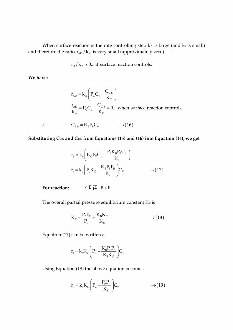
When surface reaction is the rate controlling step kA is large (and ks is small)
and therefore the ratio AD Ar / k is very small (approximately zero).
D Ar / k 0....if surface reaction controls.
We have:
C.SAD A C v
C
C.SADC v
A C
Cr k P C
K
CrP C 0....when surface reaction controls
k K
B.S B B vC K P C 16
Substituting CC.S and CB.S from Equations (15) and (16) into Equation (14), we get
P B B vS s C C v
s
B P Bs s c C V
s
P K P Cr k K P C
K
K P Pr k P K C 17
K
For reaction: C B P
The overall partial pressure equilibrium constant KP is
B CB PP
C B
K KP PK 18
P K
Equation (17) can be written as
B P Bs s C C v
S C
K P Pr k K P C
K K
Using Equation (18) the above equation becomes
P PS s C C v
P
P Pr k K P C 19
K

We can not measure Cv so we will eliminate it from the above expression by
performing a site balance.
In the present case a site balance is (the total concentration of sites is)
t v C.S B.S I.SC C C C C 20
Where Ct is the total molar concentration of active sites per unit mass of
catalyst and is equal to the number of active sites per unit mass divided by
Avogadro’s number (mol/g cat).
Now we will determine the concentration of sites occupied by the inert (CI.S)
to make use of Equation (20) to eliminate Cv from Equation (19).
I.SADI AI I v
I
CWe have, r k P C
K
When surface reaction is rate controlling kAI is very large compared to kA and
therefore the ratio rADI/kAI is very small (approximately zero).
I.SADI AI I v
I
Cr / k P C 0
K
I.S I I vC K P C 21
Putting values of CC.S, CB.S and CI.S from Equation (15), (16) and (21) into
Equatio n(20), we get
t v C C v B B v I I v
t C C B B I I v
tv
C C B B I I
C C K P C K P C K P C
C 1 K P L P K P C
CC 22
1 K P K P K P
Putting value of Cv from Equation (22) into Equation (19), we get
tP Bs S C C
P C C B B I I
S C t C P B PS
C C B I I
CP Pr k K P
K 1 K P K P K P
kk K C P P P / Kr
1 K P K K P

Let, k = ks KC Ct
The rate law (rate expression) for the catalytic decomposition of cumene
(with an inhibitor in the feed), assuming the surface reaction as the rate controlling
step, is
C P B P'C s
C C B B I I
k P P P / Kr r 23
1 K P K P K P
Where
Equation (23) is the desired rate expression for the catalytic decomposition of
cumene.
Typical units of various constants are:
13. Derive the equation of rate of adsorption of cumene with adsorption of
cumene as rate linking step?
To answer this question we shall assume that the adsorption of cumene is indeed
rate-limiting, derive the corresponding rate law, and then check to see if it is
consistent with experimental observation. By assuming that this (or any other) step
is rate-limiting, we are considering that the reaction rate constant of this step (in the
case kA) is small with respect to the specific rates of the other steps (in this case kS
and kD)Strictly speaking one should compare the product KAPc with ks and kD. (See
Summary Notes for Lecture 19 on CD-ROM. The end result is the same however.
The rate of adsorption is
Need to express Cv and Cc in terms of Pc, PB amd Pp
' .cC AD A C v
c
C sr r k P C
K
Since we cannot measure either Cv or Cc,s . We must replace these variable in the rate
law with measurable quantities for the equation to be meaningful.
For steady-state operation we have
'
C AD s Dr r r r

For adsorption limited reactions, KA is small and ks and kD are large. Consequently,
the ratios rs/ks and rD/kD are very small (approximately zero), whereas the ratio rAD/kA
is relatively large. The surface reaction rate expression is
.
.
B S p
S s c s
s
C Pr k C
K
For adsorptions limited reactions the surface specific reaction rate kg is large
by comparison and we can set
0s
s
r
K
And solve Equations for Cc,s
.
.
B s p
c s
s
C PC
K
To be able to express Cc solely in terms of the partial pressures of the species present,
we must evaluate CB-s. the rate of desorption of benzene is
.D D B s B B vr k C K P C
However, for adsorption limited reactions, kD is large by comparison and we can set.
Using 0s D
s D
r r
k K to find CB.s and Cc.s in terms of partial pressures.
0D
D
r
k
And then solve Equation for CB.s:
.B s B BC K P C
After combining Equations , we have
.
B p
c s B
s
P PC K C
K
Replacing Cc.s in the rate equation and then factoring C
We obtain
B B p B p
AD A C A C
s C p
K P P P Pr k P C k P C
K K K

Observe that by setting rAD =0, the term (KSKC/KB) is simply the overall partial
pressure equilibrium constant, Kp for the reaction
s C
P
B
C B P
K Kk
K
The equilibrium constant can be determined from thermodynamic data and is
related to the change in the Gibbs free energy G , by the equation .
In K= GRT
Where R is the ideal gas constant and T is the absolute temperature
The concentration of vacant sites, C, can now be eliminated from equation by
utilizing the site balance to give the total concentration of sites Ct,which is assumed
constant:
Since cumene and benzene are adsorbed on the surface, the concentration of
occupied sites is (Cc.s+ CB.s), and the total concentration of sites is
Site balance 1 . .c s B sC C C C
Substituting Equation into Equation, we have
1B
B P B B
s
KC C P P C K P C
K
Solving for C, we have
/B P B s B B
CC
P P K K K P
Combining Equations we find that the rate law for the catalytic decomposition of
cumene, assuming that the adsorption of cumene is the rate-limiting step, is
Cumene reaction rate law if adsorption were limiting step
1'( / )
1 /
A C p B p
C AD
B p B s B B
C k P P P Kr r
K P P K K P
Total sites = vacant sites +occupied sites

We nowwish to sketch a plot of the initial rate as a function of the partial
pressure of cumene, Pco. Initially, no product are present, consequently, Pp= PB =0.
the initial rate is given by
'
co t A co cor C K P kP
In the cumene decomposition is adsorption limited, then the initial rate will be linear
with the initial partial pressure of cumene as shown in figure.
Before checking to see if figure is consistent with experimental observation,
we shall derive the corresponding rate laws and initial rate plots when the surface
reaction is rate-limiting and then when the desorption of benzene is rate –limiting.
If adsorption were rate-limitn , the data should show '
0r increasing linearly with Pco
Figure Uninhibited adsorption limited reaction
14. Derive the equation of rate of adsorption of cumene with desorption of
Benzene as rate limiting step?
The rate expression for the desorption of benzene is
.D D B s B Br k C K P C
From the rate expression for surface reaction, equation we set
For desorption limited reactions, both kAD and ks are very large compared with kD,
which is small
0s
s
r
k
To obtain

..
C sB s s
p
CC K
P
Similarly, for the adsorption step, Equation we set
0
AD
A
r
k
To obtain
.c s c cC K PC
Then substitute for Cc.s in Equation
.
c s cB s
p
K K PCC
P
Combining Equation and gives us
c BD B c s
p p
P Pr k K K C
P K
Where Kc is the cumene adsorption constant, Ks is the surface reaction equilibrium
constant, and Kp is the gas-phase equilibrium constant for the reaction. To obtain an
expression for C, we again perform a site balance.
Site balance Ct = Cc.s +CB.s + C
After substituting for the respective surface concentrations, we solve the site balance
for C
1 /
t
c s c p c c
CC
K K P P K P
Replacing C in Equation by Equation and multiplying the numerator and
denominator by obtain the rate expression for desorption control
Cumene decomposition rate law if adsorption were limiting
1'
/
k
D s C c B p p
X D
p C C s c p C
k C K K P P P Kr r
P P K K K P P

To determine the dependence of the initial rate on partial pressure of cumene,
we again set PP =PB=0; and the rate law reduces to
If desorption controls , the initial rate is independent of partial pressure of cumene
'
Co D tr k C
With the corresponding plot of '
Cor shown in figure. If desorption were controlling.
We would see that the initial would be independent of the initial partial pressure of
cumene.
15. Derive the equation of rate of reaction of cumene with surface reaction as rate
limiting step?
The rate of surface reaction is
.
.
p B s
s s c s
s
P Cr k C
K
Since we cannot readily measure the concentration of the adsorbed species, we must
utilize the adsorption and desorption steps to eliminate CC.s and CB.s from this
equation.
From the adsorption rate expression in Equation and the conditions that kA is
large by comparison when surface reaction is controlling (i.e. / 0).AD Ar k We obtain
a relationship for the surface concentration for adsorbed cumene.
.C s c cC K PC
In a similar manner, the surface concentration of adsorbed benzene can be
evaluated from the desorption rate expression [Equation ] together with the
approximation.
Using 0AD D
A D
r r
k k to find CB.s and Cc.s in terms of partial pressures.
When B.s0 then CDB B
D
rK P C
k
Substituting for CB.s and Cc.s in Equation gives us
B pB B Ps s C C s c c
S P
P PK P Pr k P K C k K P C
k K

The only variable left to eliminate is C:
Site balance . .t B S c sC C C C
Substituting for concentrations of the adsorbed species, CB.s and CC.s yields
1 B B C C
CC
K P K P
Cumene rate law for surface reaction-limiting
'/
1
k
s t C C p B p
C s
B B C C
k C K P P P Kr r
P K K P
The initial rate is
' 1
01 1
k
s c Co CoCO
C C C Co
k C K P kPr
K P K P
At low partial pressure of cumene
1 C CoK P
And we observe that the initial rate will increase linearly with the initial partial
pressure of cumene.
'
Co Cor kP
At high partial pressures
Kc PCO 1
And Equation becomes
' PCoVCo
C co c
K kr
K P k
And the rate is independent of the partial pressure of cumene. Figure shows the
intial rate of reaction as a function of initial partial pressure of cumene for the case of
surface reaction controlling.

If surface reaction were rate-limiting, the data would show this behaviour
Figure Surface-reaction limited.

CH6701 CHEMICAL REACTION ENGINEERING – II
PART-A
1. Explain Knudsen diffusion. (NOV/DEC 2013)
If the pore size of a solid catalyst is small and as the gas is less dense, then in such cases, molecules
collide more frequently with the catalyst pore walls as compared to collisions among each other. This type of
diffusion phenomena is called Knudsen diffusion.
2. Distinguish between Knudsen diffusion and Bulk diffusion.
Bulk diffusion occurs when the pores of a solid catalyst are considerably large and the gas is
relatively dense or if the pores are filled with liquid. If the pore size of a solid catalyst is small and as the gas
is less dense, then in such cases, molecules collide more frequently with the catalyst pore walls as compared
to collisions among each other. This type of diffusion phenomena is called Knudsen diffusion. When the
reaction mixture in the pore is liquid, Knudsen diffusion does not occur.
3. Write short notes on surface diffusion.
The transport by movement of adsorbed molecules over the catalyst surface is called Surface
Diffusion. The direction of diffusion is that of the increasing surface concentration. Surface diffusion
contributes little to overall transport through a porous mass unless appreciable adsorption occurs.
4. Define Effective diffusivity. (May 2015) / (NOV/DEC 2014)
In a porous catalyst, the pores in a catalyst are not straight and they follow tortuous (zig-zag),
interconnecting paths having varying cross sectional area. To account this variation, effective diffusivity is
considered. Effective diffusion coefficient accounts for the average diffusion taking place at any position in
the catalyst pellet and it is the function of both bulk diffusivity and Knudsen diffusivity. It is denoted by
‘De’. Effective diffusivities in porous catalysts are usually measured under conditions where the pressure is
maintained constant by external means.
5. What is a Parallel pore model?
This is a geometric model of the pore system, used to convert ‘D’ to ‘De’ for the porous pellet. It is
the model based on the properties (ρs, Vg, εp), to represent the mono-disperse pore-size distribution in a
catalyst pellet. By this model, the effective diffusivity is De = εD/δ. Where ‘δ’ is the tortuosity factor, ‘ε’ is
the porosity of the pellet and ‘D’ is the diffusivity (in the absence of surface diffusion).
6. What is Random pore model?
This model was originally developed for pellets containing a bi-disperse pore system (considering
both Macro and Micro pores) to convert ‘D’ to ‘De’. By this model, the effective diffusivity is
. UNIT-III (GAS-SOLID CATALYTIC REACTORS)
Diffusion within catalyst particle, effective thermal conductivity, mass and heat transfer within catalyst
pellets, effectiveness factor, Thiele Modulus, fixed bed reactors.

De = [εM2] DM + [εµ
2 (1 + 3 εM)/ (1 - εM)] Dμ Where DM & Dμ are the diffusivities for macro and
micro pore regimes and εM & εM are the porosities for the macro and micro pore regimes.
7. What are the resistances in porous catalyst?
The resistances in porous catalyst are;
reactants (gas or liquid) into the pores of the solid catalyst
(Pore diffusion resistance or diffusional mass transfer resistance)
8. Define Thiele modulus. Give its significance. (May/June 2014) (Nov/Dec 2016)
It is a dimensionless number (denoted by ‘MT or Ф’), defined as the ratio of the intrinsic chemical
reaction rate in the absence of mass transfer limitation to the rate of diffusion through the particle. Thiele
Modulus is useful in predicting the reactor behavior from known kinetic information.
The Thiele modulus was developed by Ernest Thiele in his paper 'Relation between catalytic
activity and size of particle' in 1939. Thiele reasoned that with a large enough particle, the reaction rate is so
rapid that diffusion forces are only able to carry product away from the surface of the catalyst particle.
Therefore, only the surface of the catalyst would be experiencing any reaction. The Thiele Modulus was
then developed to describe the relationship between diffusion and reaction rate in porous catalyst pellets with
no mass transfer limitations. This value is generally used in determining the effectiveness factor for catalyst
pellets.
Thiele modulus = Reaction rate / Diffusion rate
9. Define Effectiveness factor. (May 2015) & (NOV/DEC 2014) (Nov/Dec 2016)
The effectiveness factor (denoted by ‘η’) is defined as the ratio of actual rate for the whole pellet to
the rate evaluated at outer surface conditions. (OR) It is the ratio of reaction rate with diffusion to the rate
without diffusion resistance.
The effectiveness factor η relates the diffusive reaction rate with the rate of reaction in the bulk
stream. For a first order reaction in a slab geometry,this is:
η = tan hT / hT
10. Explain the significance of effectiveness factor.
For diffusion in single cylindrical pore, follows a first order kinetics, the effectiveness factor is η =
tanh (ФL) / ФL Where ‘ФL’ is the Thiele modulus and is given by ФL = L / (k ρp / De)1/2
‘L’ is the thickness of cylindrical pore.
For small ФL (ФL < 0.4), η ≈ 1, the concentration of reactant does not drop appreciably within the
pore; thus pore diffusion offers negligible resistance. For large ФL (ФL > 4), η = 1/ФL, the reactant
concentration drops rapidly to zero on moving into the pore, hence diffusion strongly influences the rate of
reaction.
11. What is the effect of catalyst pellet size on the effectiveness factor?

In the regime of strong diffusion resistance, the rate (thus the effectiveness factor) varies inversely
proportional to the catalyst pellet size. So, Increase in pellet size will decrease the value of effectiveness
factor and vice-versa.
12. Can effectiveness factor of a catalyst be greater than one? Explain.
Yes. For exothermic reactions (only), where pore resistance just begins to intrude, the effectiveness
factor can become greater than unity; because heat is released and catalyst particles are hotter than the
surrounding fluid. (Hence, non-isothermal rate is always greater than the isothermal rate as measured by the
bulk fluid stream conditions).
13. ‘In a catalyst pellet, if the rate of diffusion through the pores is much higher than the rate of
reaction, then the value of Thiele modulus will approach unity’. Justify this statement.
By the definition, we know that the Thiele modulus is the ratio of the intrinsic chemical reaction rate
in the absence of mass transfer limitation to the rate of diffusion through the particle. If the rate of diffusion
through the pores (denominator term) is much higher than the rate of reaction (numerator term), then the
value of Thiele modulus will approach unity.
14. Write short notes on ‘Non-isothermal effectiveness factor’.
For an exothermic reaction, the temperature rises going into the pellet, the increase in rate of reaction
accompanying the temperature rise can more than offset the decrease in ate due to drop in reactant
concentration. Then „η‟ values are greater than unity. While η > 1 increase the rate per pellet, and therefore
the production per unit mass of catalyst, there may also be some disadvantages. With larger „η‟ there will be
a large increase in temperature toward the center of the pellet, resulting in sintering and catalyst deactivation.
The desired product may be subject to further reaction of unwanted product or undesirable side reactions may
occur. If these reactions have higher activation energies than the desired reaction, the rise in temperature
would reduce selectivity. For an endothermic reaction, there is a decrease in temperature and rate into the
pellet. Hence ‘η’ is always less than unity. Since the rate decreases with drop in temperature, the effect of
heat-transfer resistance is diminished.
15. Explain ‘Wagner Modulus’.
It is the modulus which accounts the pore resistance effects on the solid catalyzed reaction, which is
given by MW = MT2 η = L
2 (-rA
||| / CA)obs / De Where „MT‟ is the Thiele modulus, ‘η’ is the effectiveness
factor, ‘L’ is the characteristic size of the catalyst, (-rA|||) is the reaction rate based on the volume of the
catalyst pellet, ‘CA’ is the fluid concentration at absolute conditions and ‘De’ is the effective diffusivity.
16. When is it said that a reaction follows ideal mechanism in gas-solid catalytic reactions
If η → 1 (‘MT or Ф’ is large enough) then it is said that the gas solid catalytic reaction follows ideal
mechanism. That is, this condition means that diffusion into the pellet is relatively slow, so that reaction
occurs before the reactant has diffused far into the pellet.

17. What is Channeling?
When the gas is not evenly distributed in the catalyst bed cross section and is concentrated in
channels through the catalyst bed, the phenomena is called as Channeling of fluidized bed.
18. Define Effective thermal conductivity. (NOV/DEC 2013)
The effective thermal conductivity (ke) is the energy transferred per unit of total area of pellet
(perpendicular to the direction of heat transfer).
19. Compare fixed and fluidized - bed reactors for gas-solid catalytic operation.
pressure drop. High pressure increases the operating cost.
It is possible to use fine size catalyst particles in fluidized bed reactor. Fine size particles provide large
interfacial / contact area.
done, this problem will be bottleneck in operation.
Catalyst particle regeneration is quite easy in fluidized bed reactors. If the regeneration needs to be done
frequently, the catalyst particles can be entrained with the product stream, separated in cyclone separator and
then sent to the regenerator
20. List some of the problems that would be encountered in the operation of a fluidized catalytic
reactor.
In operation of a fluidized catalytic reactor, some difficulties can occur. They are;
Slugging of fluidized bed.
channels through the catalyst bed, the phenomena is called as Channeling of fluidized bed.
21. What is effective diffusivity?(Nov/Dec 2016) (or) Express the relationship between diffusion
coefficient and effective diffusivity with units. (Nov/Dec 2017)
The pores in the pellet are not straight and cylindrical; rather, they are a series of tortuous,
interconnecting paths of pore bodies and pore throats with varying cross-sectional areas. It would not be
fruitful to describe diffusion within each and every one of the tortuous pathways individually; consequently,
we shall define an effective diffusion coefficient so as to describe the average diffusion taking place at any
position r in the pellet. Consider only radial variations in the concentration; the radial flux WAr will be based
on the total area (voids and solid) normal to diffusion transport (i.e., 4πr2) rather than void area alone. This
basis for WAr is made possible by proper definition of the effective diffusivity De .
The effective diffusivity accounts for the fact that:
1. Not all of the area normal to the direction of the flux is available (i.e., the area occupied by solids) for the
molecules to diffuse.

2. The paths are tortuous.
3. The pores are of varying cross-sectional areas. An equation that relates De to either the bulk or the
Knudsen diffusivity is
The constriction factor, accounts for the variation in the cross-sectional area that is normal to diffusion. It is a
function of the ratio of maximum to minimum pore areas
22. What is effective thermal conductivity? Explain. (Apr/May 2017)
The effective thermal conductivity of each layer is the weighted arithmetic mean of solid and
fluid conductivities as follows:
Keff = ε kf + (1- ε)ks
In order to simplify, keff is formulated based on the following nondimensionless relationships:
d = R/L
e = r/L
24. Differentiate fluidized bed and Mixed flow reactor. (Apr/May 2017)
S.No. Fluidized bed Reactor Mixed flow Reactor
1 Fluidized bed reactor (FBR) is a type of
reactor device that can be used to carry out a
variety of multiphase chemical reactions.
MFR is also called CSTR and usually are
equipped with an agitating device (stirrer,
agitator) for mixing the reactants.
2 In this type of reactor, a fluid (gas or liquid) is
passed through a granular solid material
(usually a catalyst possibly shaped as tiny
spheres) at high enough velocities to suspend
the solid and cause it to behave as though it
were a fluid.
MFR composition of the reactant mixture
is uniform throughout the reactor and same
as that in the exit
line MFR can be both batch or
continuous.
3 Advantages The increase in fluidized bed reactor use in
today's industrial world is largely due to the
inherent advantages of the technology.
a) Uniform Particle Mixing
b) Uniform Temperature Gradients
c) Ability to Operate Reactor in
Continuous State
Advantages
a) Easy in controlling temperature in each
stage since each operates in a stationary state
b) This reactor can be readily adapted for
automatic controlling general that allowing
fast response to changes in operating
conditions for examples, feed rate and its
concentration.

c) Mixed flow reactor also have efficient
stirring and viscosity that is not too high that
good to beused.
4 Disadvantages
a) As in any design, the fluidized bed reactor
does have it draw-backs, which any reactor
designer must take into consideration.
b) Increased Reactor Vessel Size:
c) Particle Entrainment:
d)Lack of Current Understanding:
e) Erosion of Internal Components:
f) Pressure Loss Scenarios:
Disadvantages
a) For this reactor is its conversion per unit
volume of the reactor is smallest
compared to other flow reactors
b) Principle stems from the fact that the
outlet stream is the same as the contents
of the vessel. This implies that all
reaction takes place at the lowest
concentration (of reactant A, say, cA)
between inlet and outlet.
c) For normal kinetics, in which rate
of reaction ( rA) decreases as cA
decreases, this means that a greater
volume of reactor is needed
to obtain a desired conversion
25. Define effectiveness factor for diffusion through the catalyst pores.
The magnitude of the effectiveness factor (ranging from 0 to 1) indicates the relative importance of diffusion and
reaction limitations. The internal effectiveness factor is defined as

PART B

PART – B
1. With a neat sketch explain how to obtain the diffusivity of a catalyst pellet?
Considerable experimental data has been accumulated for effective
diffusivities in gas-filled pores. Since reactors normally are operated at steady state
and nearly constant pressure, diffusivities have also been measured under these
restraints. The usual apparatus is of the steady-flow type, illustrated in figure for
studying diffusion rates of H2 and N2. The effective diffusivity is define din terms of
such rates (per unit of total cross-sectional area) by the equation.
A AA e ee
g
dC dyN D D
dr R T dr
…(1)
Where the subscript e on NA emphasizes that this I a diffusion flux in a porous
catalyst rather than for a single pore, as given by Eq. (11-1). If we use the
concentration-independent diffusivity D given by Eq. De for a porous pellet will also
be constant. Then Eq. can be integrated to give
2 1A A
A eeg
y yN D
R T r
…(2)
Where r is the length of the pellet. If the flow rates and concentrations are
measured for the experiment pictured in figure. (NA)e can be calculated. Then this
flux and the measured concentrations and pellet length are substituted in eq. to
obtain an experimental effective diffusivity.
A- Mixing chambers
C-Detector for determining composition of N2 , in H2 stream
D- Detector for determining composition of H2 in N2 stream
H2
N2

E- Flow meters
P- Catalyst pellet
G- Pressure equalization gauge
Figure: Constant pressure apparatus for measuring diffusion rates in porous
catalysts.
Dynamic methods have also been used to measure De. for example, a pulse
input of diffusing component A can be inserted into a stream of helium flowing
through the upper chamber as indicated in figure. Pure helium also flows through
the lower chamber. Some of the pulse of A diffuses through the pellet and is
measured as a response pulse at the detector in the lower steam. For high flow rates
of a nonadsorbing component, the effective is given by
2
16e
rD
…(3)
Here , 1 is the first moment (retention time) of the diffusing component in the pellet.
It is obtained from the measured response pulse CA (t) by the equation.
01
0
dtA
A
C t t
C t dt
…(4)
Where CA (t) = Concentration (function of time, t) in the response pulse
p = porosity of pellet
r= length of pellet
Other equations have been developed, both for adsorbing components and
for lower flow rates across the pellet faces .
Comparison of diffusivities from steady-state and dynamic experiments can,
in principle, provide information about pore structure. For example, dead-end pores
should not affect diffusion at steady state, but would influence the results in
dynamic experiments. Actually, uncertainties of experimental results has
prevented, as yet, meaningful comparisons. Another method of evaluating effective
diffusivities, provided the rate equation for the chemical step is known, is
comparison of the observed and predicted global rates by combining the equation
for the chemical step with the intraparticle mass-transport resistance (see example
for a variation of this method)

Figure: Dynamic method for measuring diffusivities in porous catalysts
In the absence of experimental data it is necessary to estimate De from the
physical properties of the catalyst. In this case the first step is to evaluate the
diffusivity for a single cylindrical pore, that is, to evaluate D from Equation. Then a
geometric model of the pore system is used to convert D to De for the porous pellet.
A model is necessary because of complexity of the geometry of the void spaces. The
optimum model is a realistic representation of the geometry of the voids (with
tractable mathematics) that can be described in terms of easily measurable physical
properties of the catalyst pellet. As noted in Chapter, these properties are the surface
area and pore volume per gram, the density of the solid phase, and the distribution
of void volume according to pore size.
2. Describe the parallel pone and Random pore model?
The Parallel-pore Model Wheeler proposed a model, based on the first three of
these properties, to represent the monodisperse pore-size distribution in the catalyst
pellet. From s and V the porosity p is obtained from equation. Then a mean pore
radius a is evaluated by writing equations for the total pore volume and total pore
surface in a pellet. The result, developed as Equation, is
2V
aS
…(1)

By using V, S and s, Wheeler replaced the complex porous pellet with an assembly
(having a porosity, ) of cylindrical pores of radius a . To predict De from the model
the only other property necessary is the length xL of the diffusion path. If we assume
that, on the average, the pore make an angle of 45 with the coordinate r in the
resultant direction of diffusion (for exmple, the radial direction in a spherical pellet),
xL = 2 r. Owing to pore interconnections and non-cylindrical shape, this value of xL
is not very satisfactory. Hence, it is customary to define xL in terms of an adjustable
parameter, the tortuosity factory , as follows:
XL =r
An effective diffusivity can now be predicted by combining Eq. for a single
pore with this parallel-pore mode. To convert D, which is based on the cross-
sectional area of the pore, to a diffusivity based upon the total area perpendicular to
the direction of diffusion, D should be multiplied by the porosity. In equation , x is
the length of a single, straight cyclindrical pore. To convert this length to the
diffusion path in a porous pellet xL from Equation should be substituted for x. with
these modifications the diffusive flux in the porous pellet will be
Ady A e
g
DN
R T dr
…(2)
Comparison with Eq. shows that the effective diffusivity is
e
DD
…(3)
Where D is given (in the absence of surface diffusion) by Eq. The use of Equation to
predict De is somewhat limited because of the uncertainty about . Comparison of
De from equation with values obtained from experimental data for various catalysts
using Eq. shows that varies from less than unity to more than 6.
The Random-Pore Model
This model was originally developed for pellets containing a bidisperse pore
system, such as the alumina described in chapter. It is supposed that the pellet
consists of an assembly of small particles. When the particles themselves contain
pores (micropores). There exists both a macro and a micro void-volume distribution.
The voids re not imagined as capillaries, but more as an assembly of short void
regions surrounding and between individual particles, as indicated in figure. The
nature of the interconnection of macro and micro void regions is the essence of the

model. Transport in the pellet is a assumed to occur by a combination of diffusion
through the macro regions (of void fraction M)., the micro regions (of void fraction
), and a series contribution involving both regions. It is supposed that both macro
and macro regions can be represented as straight, short cylindrical pores of average
radii and aMa . The magnitude of the individual contributions is dependent on
their effective cross-sectional areas (perpendicular to the direction of diffusion). The
details of the development are given elsewhere, but in general these area are
evaluated from the probability of pore interconnections. The resultant expression
for De may be written.
2
21 3
...(4)1
MMe M
M
D D D
Here and DMD are obtained by applying Eq. to macro and micro regions Thus
1 1 1 ....(5)
1 1 1 .....(6)
D
KM ABM
AB K
D D D
D D
No tortuosity factor is involved in the mode. The actual path length is equal to the
distance coordinate in the direction of diffusion. To apply Equation requires void
fractions and mean pore radii for both macro and micro regions. The mean pore
radii can be evaluated for the micro region by applying Equation to this region.
However, Ma must be obtained from the pore-volume distribution as described in
sec. The mean pore radii are necessary in order to calculate (DK)M and (DK)µ from
Equation . Thus the random-pore model does not involve an adjustable parameter
Figure: Random-pore model.
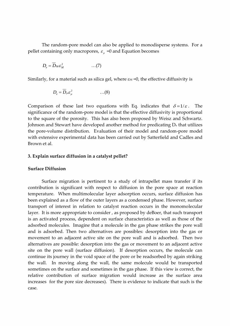
The random-pore model can also be applied to monodisperse systems. For a
pellet containing only macropores, =0 and Equation becomes
2Me MD D …(7)
Similarly, for a material such as silica gel, where M =0, the effective diffusivity is
2
eD D …(8)
Comparison of these last two equations with Eq. indicates that 1/ . The
significance of the random-pore model is that the effective diffusivity is proportional
to the square of the porosity. This has also been proposed by Weisz and Schwartz.
Johnson and Stewart have developed another method for predicating De that utilizes
the pore-volume distribution. Evaluation of their model and random-pore model
with extensive experimental data has been carried out by Satterfield and Cadles and
Brown et al.
3. Explain surface diffusion in a catalyst pellet?
Surface Diffusion
Surface migration is pertinent to a study of intrapellet mass transfer if its
contribution is significant with respect to diffusion in the pore space at reaction
temperature. When multimolecular layer adsorption occurs, surface diffusion has
been explained as a flow of the outer layers as a condensed phase. However, surface
transport of interest in relation to catalyst reaction occurs in the monomolecular
layer. It is more appropriate to consider , as proposed by deBoer, that such transport
is an activated process, dependent on surface characteristics as well as those of the
adsorbed molecules. Imagine that a molecule in the gas phase strikes the pore wall
and is adsorbed. Then two alternatives are possibles: desorption into the gas or
movement to an adjacent active site on the pore wall and is adsorbed. Then two
alternatives are possible: desorption into the gas or movement to an adjacent active
site on the pore wall (surface diffusion). If desorption occurs, the molecule can
continue its journey in the void space of the pore or be readsorbed by again striking
the wall. In moving along the wall, the same molecule would be transported
sometimes on the surface and sometimes in the gas phase. If this view is correct, the
relative contribution of surface migration would increase as the surface area
increases for the pore size decreases). There is evidence to indicate that such is the
case.

Experimental verification of surface diffusion is usually indirect, since
concentrations of adsorbed molecules on a surface are difficult to measure. When
gas concentrations are obtained , the problem arises of separating the surface and
pore-volume transport rates. One solution is to measure both NA and NB in the
apparatus shown in figures, using a nonadsorbable gas for A. If the diffusion rate of
B is greater than that calculated from NA by Equation, the excess is attributable to
surface migration. Barrer and Barrier used this procedure with Vycor at room
temperature and found surface migration significant for such gases as CO2,CH4, and
C2 H4 and negligible for helium and hydrogen Rivarolas found that for CO2 the
surface contribution on an alumina pellet increased from 3.5 to 54% of the total mas-
transfer rate as the macropore properties changed from Ma =1.710
M M and 0.33 to a 348 A and 0.12MA
By analogy to Fick’s law, a surface diffusivity Ds may be defined in terms of a
surface concentration Cs in moles of adsorbate per square centimeter of surface.
...(1)sS s
dCN D
dx
Where Ns is the molal rate per unit perimeter of pore surface. In order to combine
surface and pore-volume contributions in a catalyst pellet, the surface flux should be
based on the total area of the catalyst perpendicular to diffusion and on the
coordinate r. If this flux is (Ns)e , then
s s pe
dCN D
dr …(2)
Where r is the density of the catalyst and C now represents the moles adsorbed per
gram of catalyst. To be useful, Equation must be expressed in terms of the
concentrations in the gas phase. If the adsorption step is fast with respect to surface
transfer from site to site on the catalyst, we may safety assume equilibrium between
gas and surface concentration. Otherwise the relation between the two
concentrations depends on the intrinsic rates of the two processes. If equilibrium is
assumed, and if the isotherm is linear, then
' AA mA g A
g
yC K C C K
R T
…(3)
Where the subscript A refers to the adsorbate and K’ is the linear form of the
equilibrium constant, in cubic centimeters per gram. The latter is obtained from the

Langmuir isotherm. Equation, when adsorption is small enough that the linear form
is valid. Now, applying Equatin to component A.
' .... 4As p A se
e
dyN K D
R T dr
Equation gives the surface diffusion of A in the same form as Eq. applied earlier to
transport in the gas phase of the pores. From these equations the total flux and total
effective diffusivity are given by
e
' ...(6)
D ' ...(7)
AA e p A st
g
e p A St
dyN D K D
R T dr
D K D
If the density of the catalyst and the adsorption equilibrium constant are
known. Equation permits the evaluation of a total effective diffusivity from Ds, Data
for Ds have been reported in the literature in a variety of ways, depending on the
definitions of adsorbed concentrations and equilibrium constants. Schneider has
summarized much of the information for light hydrocarbons on various catalysts in
the form defined by Eq. such Ds values ranged from 10-3 to 10-6, depending on the
nature of the adsorbent and the amount adsorbed. Most values were in the interval
10-4 to 10-5 cm2/s. Data for other adsorbates have similar magnitudes and show that
the variation with adsorbed concentration can be large.
The effect of temperature on Ds, given an activated process, is described by an
Arrhenius type expression.
/s sE R T
sD Ae
Where Es is the activation energy for surface diffusion. The variation of K’A with
temperature is given by van’t Hoff equation.
'
A
2
' '
A
In K
K /
g
e g
d H
dT R T
or
A H R T
The observed rate of surface diffusion, according to Eq. will be proportional to the
product K’A Ds. Substituting the above expression for K’A and DS in Equation.

1/' g sR H E A
s peg
dyN AA e
R T dr
The exponential term express a much stronger temperature dependency than the
coefficient 1/T. If we neglect the latter ,we may express the temperature effect on the
rate as
1/
A
"
dy A"= AA'
dr
g sR T H E
s ee
p
g
N A
whereR T
This equation shows that the observed or apparent activation energy for surface
diffusion is related to Es by
E’=H+Es ..(8)
From a available data it appears that Es is only a few kilocalories per mole. The heat
of adsorption H is generally greater than this, particularly for chemisorption, and is
always negative. Therefore the observed effect is a decrease in rate of surface
diffusion with increase in temperature. Note that H is negative.
From the assumption and approximation presented, it is clear that surface
diffusion is not well understood. It is hoped that improved interpretations of surface
migration will permit a more accurate assessment of its effect on global rates of
reaction. When we consider the effect of intraparticle resistances in secs. We shall
suppose that the De, used is the most appropriate value and includes, if necessary, a
surface contribution.
4. Explain the concept of effective Thermal Conductivity
Concept of Effective Thermal Conductivity
The effective thermal conductivities of catalyst pellets are surprisingly low.
Therefore significant intrapellet temperature gradients can exist, and the global rate
may be influenced by thermal effects. The effective conductivity is the energy
transferred per unit of total area of pellet (perpendicular to the direction of heat
transfer). The defining equation, analogous to Eq. (11) for mass transfer, may be
written.

e e
dTQ k
dr …(1)
Where Qe is the rate of energy transfer per unit of total area
A major factor contributing to small values of ke is the numerous void spaces
that hinder the transport of energy. In addition, the path through the solid phase
offers considerable thermal resistance for many porous materiasl, particularly pellets
made by compressing microporous particles. Such behavior is readily understood if
these materials are viewed as an assembly of particles which contact each other only
through adjacent points. There is strong experimental evidence that such point
contacts are regions of high thermal resistance. For example, the thermal
conductivity of the bulk solid (zero porosity) from which the particles are prepared
does not have a large effect on ke. Masume found that the effective thermal
conducitivity of pellets of microporous particles of silver was only two to four times
that of alumina pellets, at the same macropore void fraction, pressures and
temperature. In contrast, the thermal conductivity of solid silver is about 200 times
as large as that of solid alumina. Furthermore , Ke is a strong function of the void
fraction, increasing as p decreases. Materials such as alumina pellets may be
regarded as a porous assembly within a second porous system. Each particle from
which the pellet is made contains a microporous region. These particles are in point
contact with like particles and are surrounded by macroporous regions. When
viewed in the way, the thermal conductivity of the bulk solid should have little
influence on ke.
The pressure and nature of the fluid in the pores has an effect on the effective
thermal conductivity. With liquids the effect of pressure is negligible and ke is of the
same magnitude as the true conductivity of the liquid. For gases at low pressures,
where the mean free path is the same or larger than the pore size free molecule
conduction controls the energy transfer. In this region ke increases with pressure. At
higher pressures ke is about independent of pressure. The transition pressure
depends on the gas as well as on the pore size. For air the transition pressure is
about 470 mm in a silver pellet with mean pore diameter of 1500 A. For helium the
value would be above 760 mm. For alumina pellets, at 120F and a macropore void
fraction of M= 0.40, ke was 0.050 in vacuum, 0.082 with pores filled with air, and
0.104 Btu /(h) (ft) (F)with helium, at atmospheric pressure. Temperature does not
have a strong influence. The effect is about what would be expected for the
combination of variations of thermal conductivity with temperature for the solid and
fluid phases.
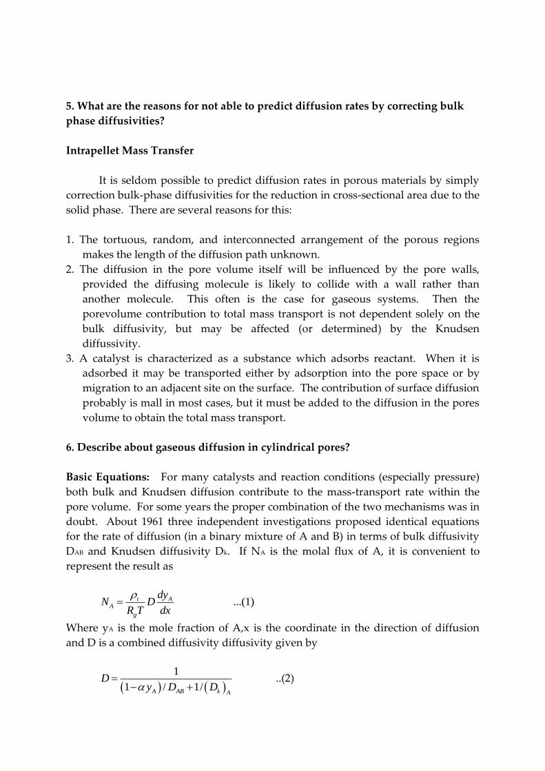
5. What are the reasons for not able to predict diffusion rates by correcting bulk
phase diffusivities?
Intrapellet Mass Transfer
It is seldom possible to predict diffusion rates in porous materials by simply
correction bulk-phase diffusivities for the reduction in cross-sectional area due to the
solid phase. There are several reasons for this:
1. The tortuous, random, and interconnected arrangement of the porous regions
makes the length of the diffusion path unknown.
2. The diffusion in the pore volume itself will be influenced by the pore walls,
provided the diffusing molecule is likely to collide with a wall rather than
another molecule. This often is the case for gaseous systems. Then the
porevolume contribution to total mass transport is not dependent solely on the
bulk diffusivity, but may be affected (or determined) by the Knudsen
diffussivity.
3. A catalyst is characterized as a substance which adsorbs reactant. When it is
adsorbed it may be transported either by adsorption into the pore space or by
migration to an adjacent site on the surface. The contribution of surface diffusion
probably is mall in most cases, but it must be added to the diffusion in the pores
volume to obtain the total mass transport.
6. Describe about gaseous diffusion in cylindrical pores?
Basic Equations: For many catalysts and reaction conditions (especially pressure)
both bulk and Knudsen diffusion contribute to the mass-transport rate within the
pore volume. For some years the proper combination of the two mechanisms was in
doubt. About 1961 three independent investigations proposed identical equations
for the rate of diffusion (in a binary mixture of A and B) in terms of bulk diffusivity
DAB and Knudsen diffusivity Dk. If NA is the molal flux of A, it is convenient to
represent the result as
...(1)t AA
g
dyN D
R T dx
Where yA is the mole fraction of A,x is the coordinate in the direction of diffusion
and D is a combined diffusivity diffusivity given by
1
1 / 1/A AB k A
Dy D D
..(2)

The quantity is related to the ratio of the diffusion of A and B by
1 B
A
N
N …(3)
Fore reactions at steady state, is determined by the stoichimetry of he reaction. For
example, for the reaction A—B, reaction and diffusion in a pore would require
equimolal counter diffusion; that is, NB =-NA. Then =0, and the effective diffusivity
is
1 ...(4)
1/ 1/AB K A
DD D
When the pore radius is large, Eqs reduce to the conventional constant-
pressure form for bulk diffusion. For this condition (Dk)A . then combining
Equations gives
t AA AB A A B
g
dyN D y N N
R T dx
…(5)
When the pore radius is large, Equs. (1) and (2) reduce to the conventional constant-
pressure form form for bulk diffusion. For the condition (DK)A . Then combining
Eqs. (1) and (3) gives
D t AA AB A A B
g
dyN y N N
R T dx
…(6)
If, in addition, the diffusion is equimolal, NB =_NA, Eq may be written
....(7)t AA AB
g
dyN D
R T dx
If the pore radius is very small, collisions will occur primarily between gas
molecules and pore wall, rather than between molecules. Then the Knudsen
diffusivity becomes very low, and Equation(1) and (2) reduce to
t AA k
g
dyN D lA
R T dx
…..(8)
This equatinis the usual one expressing Knudsen diffusion in a lon capillary.

Although Equation is the proper one to use for regins where both Knudsen
and bulk diffusion are important, it has a serious disadvantage: the combined
diffusivity D is a function of gas composition yA in the pore. This dependency on
composition carries over to the effective diffusivity in porous catalysts and makes it
difficult later to integrate the combined diffusion and transport equations. The
variation of D with yA is usually not strong (see example) Therefore it has been
almost in assessing the importance of intrapellet resistances, to use a composition –
independent form for D, for example equation. In fact, the concept of a single
effective diffusivity loses its value if he composition dependency must be retained.
Note also that the problem disappear when the reaction stoichimetry in such that
diffusion is countercurrent and equimolal.
Effective diffusivities in porous catalysis are usually measured under
conditions where the pressure is maintained constant by external means
(experimental methods are described in section) Under this condition, and for a
binary counterdiffusing systems, the ratio NB/NA is the same regardless of the extent
of Knudsen and bulk diffusion. Evans et al have shown this constant ratio be fat
constant pressure).
B
A
A
B
N
N
or
M =1 -
M
A
B
M
M
..(9)
Where M represents the molecular weight. Equations applies for nonreacting
conditions. When reactions occurs, stoichiometry determines .
7. Describe about liquid diffusion in cylindrical pores?
Diffusion in Liquids
The mean free path in liquids is to small that Knudsen diffusion is not
significant, Thus the diffusion rate is unaffected by a pore diameter and pressure (in
the absence or surface diffusion). The effective diffusivity is determined by the
molecular diffusivity and the pore structure of the catalyst pellet. Since the
molecules in liquids are close together, the diffusion of one component is strongly
affected by the force fields of nearby molecules and at the pore wall. As a result,
diffusivities are concentrations dependent and difficult to predict. As an
approximation, we may express the diffusion flux of component A in a single
cylindrical pore as:

...(1)AA AB
dCN D
dx
Where DAB is the molecular diffusivity of liquid A in a solution of A and B and
dCA/dx is the concentration gradient in the direction of diffusion.
Values of DAB are much les than those for gases and are, in general, of the
order of 1 ×10⁻⁵ cm2 /s. for gases (for example, hydrogen) dissolved in liquids the
diffusivity can be an order of magnitude larger, as noted in Examples. Several
correlations are available for estimating diffusivities in liquids at low concentrations
(infinite dilution). These may be used as approximation values in reactor problems
but he uncertain and sometimes large effect of concentrations on DAB should not be
forgotten.
The major need for liquid-phase diffusivities is in problems involving slurry
or trickle-bed reactors. Even though a gas phase is present, the wetting of the
catalyst particles by the liquid means that the pores will be essentially filled with
liquid. Since diffusivities in liquids are lower than those in gases, internal trans[part
resistances can have a large effect on the global rate for trickle-bed reactors than for
gas-solid (two phase), fixed-bed reactors. The effect is illustrated in example. Even
in slurry reactors employing catalyst particles of the order of 100 microns diameter,
intraparticle diffusion can affect the global rate.
8. Write about Surface diffusion?
Surface Diffusion:
Surface migration is pertinent to a study of intrapellet mass transfer if its
contribution is significant with respect to diffusion in the pore space at reaction
temperature. When multimolecular-layer adsorption occurs, surface diffusion has
been explained as flow of the outer layers as a condensed phase. However, surface
transport of interest in relation in catalytic reaction occurs in the monomolecular
layer. It is more appropriate to consider, as proposed by deBoer, that such transport
is an activated process, dependent on surface characteristics as well as those of the
adsorbed molecules. Imagine that a molecule in the gas phase strikes the pore wall
and is absorbed. Then two alternatives are possible: desorption into the gas or
movement to an adjacent active site on the pore wall (surface diffusion). It
desorption occurs, the molecule can continue its journey in the void space of the
pore or be readsorbed by again striking the wall.

In moving along the wall, the same molecule would be transported
sometimes on the surface and sometimes in the gas phase. If this view is correct, the
relative contribution of surface migration would increase as the surface area
increases (or the pore size decreases). There is evidence to indicate that such is the
case.
Experimental verification of surface diffusion is usually indirect, since
concentrations of adsorbed molecules on a surface are difficult to measure. When
gas concentrations are obtained, the problem arises of separating the surface and
pore-volume transport rates. One solution is to measure both NA and NB in the
apparatus shown in figure using a nonadsorable gas for A. if the diffusion rate of B
is greater than that calculated from NA by Equation, the excess is attributal to surface
migration. Barrer and Barrer used this procedure with vycor at room temperature
and found surface migration significant for such gases as CO2, CH4 and C2H4 and
negligible for helium and hydrogen. Rivarolas found that for CO2, the surface
contribution on an alumina pellet increased from 3.5 to 54% of the total mass-
transfer rate as the macropore properties changed from
Ma =1.710 A and M = 0.33 to Ma =348 A and M = 0.12
BY analogy to Fick’s law, a surface diffusivity Ds may be defined in terms of
surface concentration Cs in moles of adsorbate per square centimeter of surface.
..(1)ss s
dCN D
dx
Where N, is the molal rate per unit perimeter of pores surface. In order to combine
surface and pore-volume contributions in a catalyst pellet, the surface flux should be
based on the total area of the catalyst perpendicular to diffusion and on the
coordinate r. If the flux is (Ns)e, then
s s p
dcN D
dr (2)
Where p is the density of he catalyst and C now represents the moels adsorbed per
gram of catalyst. To be useful, equation must be expressed in terms of the
concentration in the gas phase. If the adsorption step is fast with respect to surface
transfer from site to site to the catalyst. We may safely assume equilibrium between
gas and surface concentration. Otherwise the relation between the two

concentrations depends on the intrinsic rates of the two processes. If equilibrium is
assumed, and if the isotherm is linear, then
' AA mA g A
g
yC K C C K
R T
(3)
Where the subscript A refers to the adsorbate and K’ is the linear from fo the
equilibrium constant, in cubic centimeters per gram. The latter is obtained from the
Langmuir isotherm. Equation, when adsorption is small enough that the linear form
is valid. Now, applying Equation to component A.
' ...(2)As p A
g
dyN e K
R T dr
Equation gives the surface diffusion of A in the same form as Equation applied
earlier to transport in the gas phase of the pores. From these equation the total flux
and total effective diffusivity are given by
e
' ..(3)
D ' ...(4)
AA e p A st
g
e p A st
dyN D K D
R T dr
D K D
If the density of the catalyst and the adsorption equilibrium constant are
known, equation permits the evaluation of a total effective diffusivity from Ds, Data
for Ds have been reported in the literature in a variety of ways. Depending on the
definition of adsorbed concentrations and equilibrium constants. Schneider’s has
summarized much of the information for light hydrocarbons on various catalysts in
the form defined by Equation. Such Ds values ranged from 10-3 to 10-6, depending on
the nature of the adsorbent and the amount adsorbed. Most values were in the
interval 10-4 to 10-5 cm2/s. Data for other adsorbates have similar magnitudes and
show that the variations with adsorbed concentration can be large.
The effect of temperature on Ds, given an activated process, is described by an
Arhenius –type expression.
/s gE R T
sD Ae
Where Es is the activation energy for surface diffusion. The variation of K’A with
temperatue is given by van’t Hoff equation

'
A
2
In K
dT g
d H
R T
Or
/' ' gH R T
AK A e
The observed rate of surface diffusion, according to Equation will be proportional to
the product '
A sK D , Substituting the above expression for '
AK and Ds in equation
1/
'A
g s
dyR T H E
drs pe
g
N AA eR T
The exponential term expresses a much stronger temperature dependency than the
coefficient 1/T. If we neglect the latter, we may express the temperature effect on
the rate as
1/
A
"
dy A" =AA'
dr
g sR T H E
s e
p
g
N A e
whereR T
This equation shows that the observed or apparent activation energy for surface
diffusion is related to Es by
E’=H+Es
From available data it appears that Es is onlya few kilocalories per mole. The heat of
adsorption H is generally greater than this, particularly for chemisorption, and is
always negative. Therefore the observed effect is a decease in rate of surface
diffusion with increase in temperature. Note that H is negative.
From the assumption and approximation presented, it is clear that surface
diffusion is s not well understood. It is hoped that improved interpretations of
surface migration will permit a more accurate assessment of its effect on global rates
of reaction. When we consider the effect of intraparticle resistance in secs. 11-7 to 11-
12 we shall suppose that the De used in the most appropriate value and includes, if
necessary, a surface contribution.

9. Derive the general expression for effectiveness factor
Effectiveness Factors
Suppose that an irrevisible reaction A B is first order, so that for isothermal
conditions r=f(CA) =k1 CA. then Equation becomes
rp = k1 (CA)s
We want to evaluate in terms of Ds and k1. The first step is to determine the
concentrations profile of A in the pellet. This is shown schematically in figure for a
spherical pellet (also shown is the external profile from Cb to Cs). The differential
equation expressing CA vs. r is obtained by writing a mass balance over the spherical
shell volume of thickness r. According to Equation at steady state the rate of
diffusion into the element less the rate of diffusion out will equal the rate of
disappearance of reactant within the element. This rate will be pk1 CA per unit
volume, where p is the density of the pellet Hence the balance may be written,
omitting subscript A on C.
2 2 2
p 14 4 4 re e
r r r
dC dCr D D r k C
dr dr
The diffusive flux into the element is given by Equation. Note that for Ab there is
equimolal counter diffusion of A and B (=0). The rate of diffusion is the product of
the flux and the area. 24 r . If we take the limits as 0r assume that the effective
diffusivity in independent of the concentration of reactant (see sec), this difference
equation becomes.
2
1
2
20
p
e
kd C dCC
dr rdr D
At the center of the pellet symmetry requires
0 at r=0dC
dr
And at the outer surface
C=Cs at r= rs
Linear differential equation with boundary conditions (11-47) and (11-48) may be
solved by conventional methods to yield

s
sinh 3 /
sin h 3
s s s
s
r r rC
C
Where , is a dimensionless group (a Thiele-type modulus for a spherical pellet)
defined by
1
3
pss
e
kr
D
The second step is to use the concentrations profile given by Equation, to evaluate
the rate of reaction rp for the whole pellet. We have two choices for doing this:
calculating the diffusion rate of reactant into the pellet at rs, integrating the local rate
over the whole pellet, Choosing the first approach.
21 34
s
p s e e
r rs r rp s p
dC dCr r D D
m dr r dr
Where the mass of the pellet is mp = 24
3s pr . Then from Equation
=1
3
s
e
r rs p s
D dC
r k C dr
Differentiating equation evaluating the derivative at r=rs, and substituting this into
Eq. gives
s
1 1 1
tan h 3 3s s
If this equation for the effectiveness factor is used in Equatin, the desired rate for the
whole pellet in terms of the concentrations at the outer surface is
1
s
1 1 1
tan h 3 3p s
s
r k C

10. Derive the equation for diffusion and reaction in a catalyst pellet?
We now perform a steady-state mole balance on species A as it enters, leaves
and reacts in a spherical shell of inner radius r and outer radius r+ r of the pellet
(figure). Note that even though A is diffusing inward toward the center of the pellet,
the convention of our shell balance dictates that the flux be in the direction of
increasing r, We choose the flux of A to be positive in the direction of increasing r
(i.e., the outward direction). Because A is actually diffusing inward, the flux of A
will have some negative value, such as -10 mol/m2., indicating that the flux is actually
in the direction of decreasing r.
First we will drive the concentration profile of reactant A in the pellet
Figure: Shell balance on catalyst pellet
We now proceed to perform our shell balance on A. The area that appears in
the balance equation is the total area (void and solids) normal to the direction of the
molar flux.
Rate of A in at r = WAr , area = WA × 4r2 r
Rate of R at (r+ r) = WAr ‘ area = WA,r ×4r2 r r
'
A
of
generation of of reaction catalyst of shell
A withing a shell of catalyst
thickness of r
= r
rate
rate massvolume
mass volume
2
c m 4 rr

Mole balance for diffusion and reaction inside the catalyst pellet
Where rm is some mean radius between r and r that is used to approximate the
volume Vof the shell.
The mole balance over the shell thickness r is
(in at r) – (out at r +r)+ (generation within r) =0
2 2 ' 24 4 4 0Ar Ar A c mr r rW r W r r r r
After dividing by (-4r) and taking the limit as r 0, We obtain the
following differential equation.
2
' 2 0Ar
A c
d W rr r
dr
Because 1 mole of A reacts under conditions of constant temperature and
pressure to form 1 mol of B, We have EMCD at constant total concentrations
The flux equation
A AAr e e
dy dCW cD D
dr dr
Where CA is the number of moles of A per dm3 of open pore volume (i.e.,
volume of gas) as opposed to (mol/vol of gas and solids). In systems where we do
not have EMCD in catalyst pores, it may still be possible to use Equation if the
reactant gases are present in dilute concentration.
After substituting Equation into equation we arrive at the following
differential equation describing diffusion with reaction in a catalyst pellet.
2
2 '/
0e A
c A
d D dC dr rr r
dr
We now need to incorporate the rate law. In the past we have based the rate
of reaction in terms of either per unit volume.

3[ ] / .Ar mol dm s
Inside the pellet
-rA = c (-rA’)
-rA’=Sa (-rA”)
-rA = c Sa _rA”)
Or pet unit mass of catalyst
-rA’[=] (mol/g cat.s)
When we study reactions on the internal surface area of catalysts, the rate of reaction
and rate law are often based on per unit surface area,
" 2[ ]( / . )Ar mol m s
As a result , the surface area of the catalyst per unit mass of catalyst.
Sa [=] (m2/g cat).
Is an important property of the catalyst. The rate of reaction per unit mass of
catalyst – rA’ and the rate of reaction per unit surface area of catalyst are related
through the equation.
Sa: 10 grams of catalyst may cover as much surface area as a football field
-rA’ =- r”A Sa
A typical value of S0 might be 150 m2/g of catalyst.
The rate law- As mentioned previously at high temperature, the denominator of the
catalytic rate law approaches 1: Consequently, for the moment, it is reasonable to
assume that the surface reaction is nth order in the gas-phase concentration of A
within the pellet.
" n
A n Ar k C
Where
1
3
n: k
n
n
A
m mr
kmol s
Similarly,

1
3 3'
a1
2
1
1
1
a first catalystic reaction S
per unit surface Area : / .
unit Mass of catalyst k' [ / . ]:
unit volume k=k
n
A n
a
Aa c
For m mr k
k m s kmol kg s
Per k S m kg sr
Per S p s
13
c
1
n
a n
mS k
kmol s
Substituting the rate law equation into equation gives
2
2/
0e A n
n a c A
d r D dc drr k S C
dr
By differentiating the first terms and dividing through by –r2 D2, Equation becomes
Differential equation and boundary conditions describing diffusion and reaction in
catalyst pellet
2
2
20nn a cA A
A
e
k Sd C dCC
dr r dr D
11. Derive the equation for effectiveness factors for a first order reaction?
Single Cylindrical Pore + First Order Reaction: Consider a single cylindrical
catalyst pore of length L as shown in figure. Further consider that reactant A
diffuses into the pore, reacts on the surface (walls of pore) by a first order reaction
and product diffuses out of the pore.
The reaction and rate based as unit surface are given by
PrA oduct " 1"A
A A
dNr k C
S dt

Figure: A straight cylindrical pore and reactant concentration distribution along
pore length
Figure: Elementary slice of catalyst pore
Figure: shows the elementary section of the catalyst pore of length x. A steady state
material balance for a reactant A across this elementary section is
Input of A= output of A + disappearance of A by reaction
Output of A – input of A+ disappearance of A by reaction =0
The individual terms in mol A/s are as follows:
Reactant A entering by diffusion (at xin ,i.e. at x):
2 2AdC D - sectinal area of the section
dxin In
dNr r cross
dt

Reactant A leaving by diffusion (at xout, i.e. , at x+x):
2A
outout
dN dCr D
dt dt
Disappearance of reactant A on surface by reaction:
rate of dissappearance of A of A by reaction=
surface
1 = -
S
A
Disappearance surfaceunit
dNsurface
dt
A =k"C (2 . )r x
The surface on which reaction is occurring = S= D .x= 2r x
Entering all these terms in Equation gives
2 2 " 2 0AA
out in
dCdCr D r CD k C r x
dx dx
Changing sign and dividing by r2 D x throughout gives
2 "0
A A
out InA
dC dC
kdx dxC
x Dr
[For any quantity Q which is a smooth continuous function of x
lim 2 12 1
02 1
lim ]x
Q Q Q dQx x
x x x dx
So taking the limit as 0,x we obtain the following second order
differential equation.
2
2
2 "0A
A
d C kC
dx Dr
Here as the rate is based on unit surface area of the wall of the catalyst pore k” has
the unit of length per time (m/s)
The interrelation between rates on different bases is given by
(-rA) V= (-rA’) w= (-rA”) S
In terms of rate constant it becomes

kV=k’W =k’s
Therefore for cylindrical catalyst pore
K= k”2
area 2 2 "" " ..
S surface rL kk k
V volume r L r
So in terms of volumetric units, Equation (6.3 becomes)
[substituting k for 2k “/r in Equation , we get
With this equation becomes
2
2
20A
A
d Cm C
dx
We seek the particular solutions of the above equation in the form:
22A
2
dC
dx
Ax
A
Ax AxA
C e
d Cthen Ae and A e
dx
So equation becomes
A2 eAx – m2 eAx =0
Hence , A= ±m
Thus, the particular solutions of Equation are:
CA = emx and CA = e-mx
General solution of Equation is the linear combination of the particular solution
CA = M1 emx +M2 e-mx
(Where M1 and M2 are constant) of integration
General solution of the linear differential equation[Equation (6.7) us
CA = M1 emx + M2 e-mx
2
2
2
d 0
k/D =m
AA
C kC
dx D
Let

Where, m= / = 2k"/Drk D
And where M1 and M2 are arbitrary constants of integration
Let us evaluate M1 and M2 using the boundary conditions
The boundary conditions are:
(i) At the pore entrance, the concentration is CAS:
CA =CAs at x=0
(ii) There is no flux or movement of material through the interior end of he pore
0 at x=LAdC
dx
With CA = CAs as x=0 Equation becomes
CAs = M1 + M2
We have CA = M1 emx + M2 e-mx
1 2 M Mmx mxAdCm e m e
dx
With dCA/dx =0 at x=L the above becomes
0= mM1 emL – m M2 e-mL
M1 emL – M2 e-mL =0
Combining Equations gives
1 1
1
1
2
0
0
M
, M
mL
mL As
mL mL mL
As
mL
As
mL mL
mL
As
mL mL
M e C M e
M e e C e
C e
e e
C eSimilary
e e
Substituting M1 and M2 from Equation into Equation gives

. .mL mx mL mx
As AsA mL mL mL mL
m L x m L x
A As mL mL
C e e C e eC
e e e e
e eC C
e e
The dimensionless concentration profile of reactant A within the proe is
cosh m L-x
cosh mL
m L x m L x
A
mL mL
As
C e e
C e e
[As cosh mL = 2
mL mLe e
Cosh m(L-x) =
2
m L x m L xe e
xe
cosh x= ]2
xe
Figure shows the concentrations profile of reactant within the pore and it is seen to
be dependent on the dimensionaless quantity mL, or MT, called the Thiele modulus.
Figure: Distribution and average concentration of reactant is a catalyst pore as a
function of mL (Thiele modulus) for first order surface reaction.
Now, we define the quantity called the effectiveness factor to measure how
much the reaction rate is lowered due to the resistance of pore diffusiom.

It is defined as the ratio of actual average reaction rate within the pore to the
reaction rate in the absence of pore diffusion resistance.
average reaction rate within pore
rate in the absence of pore diffusion resistance
actual average reaction rate within pore =
rate that would result of enterire pore surface
actual
reaction
reaction
As
wree exposed
to condition at the external surface /pore mouth C , sT
The rate of reaction in the absence of pore diffusion resistance is the
maximum rate of reaction. The rate of reaction will be maximum when the
concentration of reactant along the pore is the same as that at the external surface ,
CAS
with diffusion
without diffusin resistance
A
A
r
r
The actual rate is also referred to as the observed rate of reaction, (-rA)obs.
The effectiveness factor ranges from 0 to 1.
For first order reactions as the rate is proportional to the concentration, the
effectiveness factors is given by
order /Afirst AsC C
Evaluating the average rate in the pore from Equation yields the following
relationship
order
order
tanh mL
Let us obtain the realtinship given by Equations
For first-order reactions:
A
first
As
A A
first
As As
C
mLC
kC C
kC C

0
0
0
is given by
1 C
A
L
A L
A AL
C
C dx
C dxL
dx
With this , becomesAC Equation
order
0
1L
first A
As
C dxLC
We have,
A
cosh m L-x
cosh mL
m L-x C
cosh mL
A
AS
AS
C
C
CoshC
Substituting CA into Equation in terms of CAs gives
order
0
As
As 0
0
0
cosh ( )1
cosh mL
C = cosh m L-x
LC cosh mL
1 = cosh
L cosh mL
1 1 = sinh m L-x
Lcosh mL
-1 = 0
mL cosh mL
L
Asfirst
AS
L
L
L
C m L x dx
LC
dx
m L x dx
m
sh
first order
sin h mL =
cosh mL
tanh mL
in mL
mL
mL

12. What is the effect of heat transfer during reaction for a catalyst pellet?
Heat Effects (Exothermicity/ endothermicity) During reaction:
In faster reactions, there heat released (or absorbed) in the pellet can not be
removed rapidly enough to keep the pellet close to the temperature of the
surrounding fluid and consequently non-thermal conditions prevail. In such cases,
the following types of temperature effects may he encountered.
(i) particle T: A temperature gradient may exist within the pellet –
temperature varies within the catalyst pellet.
(ii) Film T: A temperature gradient may exist across the fluid film (between
the outer surface of pellet and main gas stream). The whole pellet may be
hotter (or colder) than the surrounding fluid, though uniform in
temperature.
In case of exothermic reactions, heat is generated and particles are hotter tan the
surrounding fluid. Consequently, the non-isothermal rate (of reaction) is higher
than the isothermal rate which is based on the bulk stream condition conditions. On
the other hand, in case of endothermic reactions, heat is absorbed and the particles
are cooler than the surrounding fluid. Consequently, the non-isothermal rate is
lower than the isothermal rate.
Thus we would encourage nonisothermal behaviour in exothermic reactions
provide no harmful effects of thermal shock, or sintering of the catalyst, or drop in
selectivity occur with hot particles. On the other hand , we would like to depress
nonisothermal behaviour in endothermic reactions.
The following simple calculation will give us idea regarding the form of non-
thermal effect that may present if at all.
(i) Film T: To find maximum T across the film, the rate of heat generation by
reaction within the pellet is set equal to the rate of heat removal through the film.

""
generated obs
"" 3
"
Aobs
r
=Q
[ . . ] cat 's / A
-r reaction rate
- H of reaction/enthalpy change re
pellet A
pellet Aobs r
V r Hr
kJV r H m kJ s
mol
observed
heat
pellet pellet p
'
generated
sulting from reaction
V of pellet =S L =V /
L- Characteristics size of the pellet
Q .
p
Aobs
Volume L as S
Spellet L r Hr
Rate of heat removal through the film- Qremoved = h. Spellet (Tg –Ts)
h= film heat transfer coefficient , kJ/ (m2,s.K)
Tg – temperature of main gas stream /bulk gas,K
Ts – temperature at the outer surface of the pellet , K
Qremoved = Q generated
h- Spellet (Tg –Ts) = Spellel . L "' .Aobe rr H
"'
film
Aobs r
g s
L r HT T T K
h
(ii) Particle T: In steady state, the heat flux within an elementary thickness of the
particle is balanced by the heat generated by chemical reaction. At any point in the
pellet,
Aeff e r
dCdTK D H
dx dx
For the pellet as w whole, integrating above equation from the exterior surface
where T=TB and Ca = CAs to the centre of the particle where say T= Tcentre and CA = CA
centre we obtain.
centre = Te As Acentre r
s
eff
D C C HTparticle T
k

Where keff is the effective thermal conductivity of the particle, J/s.m.cat.K).
When Thiele modulus is large, CAcentre is zero and consequently the maximum
temperature difference between the centre and exterior surface of the particle is DE (-
Hr) CAs / Keff.
13. The result of kinetic runs on the reaction A R made in an experimental
packed bed reactor using a fixed feed rate FAo = 10 kmol/h are as follows
W, kg
catalyst
1 2 3 4 5 6 7
XA 0.12 0.20 0.27 0.33 0.37 0.41 0.44
(i) Find the reaction rate at 40% conversion
(ii) For a feed rate of 400 kmol/ h to large scale packed bed reactor find the
amount of catalyst needed for 40% conversion.
(iii) Find the amount of catalyst that would be needed in part (II) if the
reactor employed a very large recycle of product stream.
Solution:
A R
(i) Finding the reaction rate at 40% conversion in an experimental packed bed
reactor.
The kinetic data provided at fixed feed rate (FA0 = 10 kmol/h) are:
The conversion as a function of the amount of catalyst used
For a packed bed reactor, the performance equation is
'
0
A
A A
dXW
F r
In differential form, it becomes
' A
Ao A
dXdW
dF r

In differential form, it becomes
'
0
'
A
A A
A
Ao A
dXdW
dF r
dxWd
R r
'
0
AA
A
dXr
Wd
F
If we construct a plot of XA 0
/ the given kinetic data thenA
Wv s from
F
'
0
AA
A
dXr
Wd
F
is the slope of the curve
So plot XA v/s 0A
W
F and find the slope of the curve at 40% conversion to get the
reaction rate ' at Ar 40% conversion
For’ FA0 = 10 kmol/h
W 1 2 3 4 5 6 7
Ac
W
F
0.10 0.20 0.30 0.40 0.50 0.60 0.70
XA 0.12 0.20 0.27 0.33 0.37 0.41 0.44
Draw tangent to the curve at a point P i.e. at XA = 0.40 and measure the slope
From figure.
' kmol converted at a point P=0.38
catalyst.hAr slope
kg
'
A reaction rate=-r 40% 0.38 ...( ) catalyst.h
kmol convertedThe at conversion i
kg
(ii) Determination of amount of catalyst needed in a packed bed reactor for FA0 = 400
kmol/h to achieve 40% conversion.
Refer fig (b)

Read x- coordinate of a point P i.e. 0
W
FlA for XA = 0.40 [ 40 % convension]
0
A0
A0
0.57 at 40% conversion
F 400 /
0.57 F
=0.57 400 =228 kg
A
W
F
kmol h
W
…(ii)
(iii) Find the amount of catalyst needed in a packed bed reactor employing a very
large recycle of product stream.
With a very large recycle of product stream (i.e large recycle ration) mixed flow is
approached so here we will use the performance equation for mixed flow.
'
0
A
A Aout
XW
F r
'
out A
kmol X 0.40 = 0.38
kg catalyst.hAr at
0
0.40
400 kmol/h
A
A
X
F
0
'
out
.A A
A
F XW
r
400 0.40
0.38
= 421 kg
….(iii)
Amount of catalyst needed in the large scale packed bed reactor = 228
kg
Amount of catalyst needed in a packed bed reactor employing a very large recycle of
product stream = 421 kg

Figure(a)
Figure (b)

14. The following kinetic data are obtained in a basket type mixed reactor. The
catalyst is porous. Assuming isothermal behaviours interpret the data interms of
controlling resistances.
Data:
Pellet diameter Concentration in
reactant in the
exit stream
Spinning rate
of baskets
Measured
reactions rate '
Ar
1 1 High 3
2 1 Low 1
3 1 High 1
Solution:
Run dp CA RPM Rate
1 1 1 High 3
2 3 1 Low 1
3 3 1 High 1
Examine the data for its interpretation in terms of controlling resistances
Look at run -2 and run-3 (for large particles)
These two runs use different spinning rates but have the same reaction rate.
For diffusion to control higher the spinning rate higher will be the kg and hence rate.
But for run-3 though the spinning rate is higher compared to run-2 the measured
reaction rate is same as that for run-2 (not higher than that for run-2). Therefore ,
film diffusion is not controlling resistance for large particles.
Since the film diffusion is not controlling for a large pellets, it will not
controlling in case of small pellets (run-1)
First conclusion: Film diffusion resistance is not controlling i.e. film diffusion
resistance does not influence the rate.
Now we will check for pore diffusion resistance (to be controlling resistance)

In the regime of strong pore diffusion resistance
'
A
A1 21 2
A2 1
1 -r
R
-r. . ................. be satisfied for particles of sizes R R
-r
Ri e should and
R
Compare run-1 with either run -2 or -3
Run -1 and -2:
'
1 1
'
2 2
'
1
'
2
13 R
2
31 R
2
33
1
A
A
A
A
r
r
r
r
And
2
1
'
A1 2
'
A2 1
3
2 and 31
2
-r ........ satisfied
-r
R
R
Ris
R
Same result in obtained by comparing run - 1
3 with run -3
'
31
'
3 1
3R3 23 and 3
11 R
2
A
A
r
r
As the rate is inversely proportional to particle size, the pore diffusion
resistance is controlling the rate. Therefore, the runs are conducted in the regime of
strong pore resistance.
Final conclusion/final interpretation of data:
Negligible film diffusion resistance
Strong pore diffusion resistance.

15. The observed rate using a cube of 2 cm catalyst pellet is 10-3 mol/ (s.cm3 cat).
Calculate the value of firs: order reaction rate constant. The effective diffusivity is
0.1 cm2/s and concentration of reactant at the exterior surface of pellet is 2 × 10⁻⁴
mol/cm3.
Solution:
The characteristic size of cube of side 2 cm is
3
of particle pellet
surface availeble for reactant penetration
a 3 = , of cube
6 6
VolumeL
Exterior
a sidea
Given: Side of cube = a= 2 cm
2 L= 0.333
6cm
For first order reaction A R
"'
A
T
"' TA
-r "'
tanh M =
tanh M -r "
As
T
As
T
k C
whereM
k CM
We have MT =
0.5
"'... order reaction
e
KL first
D
0.5
e"'
A 0.5
e
K'""' tanh L
D -r
K"'L
D
Ask C
Given :

"' 3 3
2
e
4 3
0.05
4
3
0.5
0.5
0.5
0.5 0.5
10 /( . cat)
L= 0.333 cm, D 0.01 /
2 10 /
k"'2 10 "' tanh 0.333
0.0110
k'''0.333
0.01
"' tanh 3.33 k"'5
3.33 '"
"' tanh 3.33 k"' 1
A
As
r mol s cm
cm s
C mol cm
k
k
k
k
6.65
We can obtain value of k”’ by trial and error procedure. Assume k”’ and check for
LHS = RHS
K’” = 200 LHS =14.14 RHS = 16.65
K”’ = 270 LHS = 16.43 RHS = 16.65
K’” = 278 LHS = 16.67 RHS = 16.65
K”’ = 277.2 LHS = 16.649 RHS = 16.65
LHS = RHS for k”’ = 277.2s-1
… Ans
Units of k”’ cm3 gas/ (cm3 cat.s) = s-1
As tanh [ 3.33 (k”)0.5 for k “’ > 2.3 is 1, we can use easy approach (for getting k”’) as
given below
A R ……. First order reaction
-rA”’ = k”’ CAs
Assume strong pore resistance
For strong pore resistance
First order rate constant = k”’ = 277.2 s-1

"
0.50
'''
0.50
1
"
"'
"'
"'
T
AsA
T
T
e
AsA
e
M
k Cr
M
kM L
D
k Cr
kL
D
"'
0.50
0.50
2"'
A
2-3
4
-1
"'
-r 1 k"'=
10 0.333 1 =
2 10 0.01
= 277.2 s
A
As e
As e
r Lk
C D
L
C D
First order rate constant = k”’ = 277.2 s-1
Units of k”’ cm3 gas/ cm3. cat. s)

CH6701 CHEMICAL REACTION ENGINEERING – II
1. Give the industrial importance of Gas-Solid non-catalytic reactions.
Gas-Solid non-catalytic reactions are employed in; (Solids does not appreciably change in size during the
reaction)
Roasting of ores.
The preparation of metals from their oxides in reducing atmospheres.
The platting of metals.
Reactions of carbonaceous materials.
Reactions in which solids change in size
Manufacture of carbon disulfide [CS2 (gas)]
Manufacture of sodium cyanide [NaCN (liquid)]
Manufacture of sodium thio sulfate [Na2S2O3 (solution)]
Dissolution reactions
Attack of metal chips by acids
Rusting of iron
2. Give two examples of fluid-solid reaction in which the particles do not change their size on reaction.
form crushed and sized magnetic ore in continuous-countercurrent, three stage, fluidized bed
reactors according to the reaction
Fe3O4 (s) + 4 H2 (g) → 3 Fe (s) + 4 H2O (g)
C (s) + H2O (g) → CO (g) + H2 (g)
C (s) + 2 H2O (g) → CO2 (g) +2 H2 (g)
3. Name the models used in gas-solid non-catalytic reactions. (NOV/DEC 2013) For the Gas-Solid non-catalytic reactions, two idealized models are available; (i) Progressive-conversion model
[PCM] (ii) Shrinking-core model [SCM]
4. Briefly explain the Progressive Conversion Model for the gas-solid non-catalytic reactions.
Solid reactant is converted continuously and progressively throughout the particle.
The reaction rates are different at different locations within the particle.
This model does not match with the real situations.
5. Explain Progressive Conversion Model. [Dec 2012]
Solid reactant is converted continuously and progressively throughout the particle.
The reaction rates are different at different locations within the particle.
This model does not match with the real situations.
6. In the ‘Shrinking Core Model’ for gas-solid non-catalytic reactions, explain the term ‘Shrinking Core’. Shrinking Core means, at any time, there exists an unreacted core of material which shrinks in size during
reaction.
7. Explain the mechanism of Shrinking Core Model.
At any time there exists an unreacted core of material which shrinks in size during reaction.
UNIT-IV (GAS-SOLID NON-CATALYTIC REACTORS)
Models for explaining kinetics; volume and surface models; controlling resistances and rate controlling
steps; time for complete conversion for single and mixed sizes, fluidized and static reactors.

The reaction rate depends on the movement of unreacted core and the resistances involved in it.
Most of the practical situations (burning of coal, wood, briquettes, etc.) show that this model
approximately matches with reality.
8. What are the limitations of Shrinking Core Model? (May 2015) (NOV/DEC 2014) (May June 2014)
It is the best simple representation for the majority of reacting gas-solid systems. However, there are two broad
exceptions to this statement;
First, Slow reaction of a gas with a very porous solid will not fit to the reality.
Second, when solid is converted by the action of heat and without needing contact with gas – Such as
baking bread, roasting chickens are mouth watering examples of such reactions.
9. What are the advantages of FBR? (NOV/DEC 2013)
Uniform Particle Mixing: Due to the intrinsic fluid-like behavior of the solid material, fluidized beds do not
experience poor mixing as in packed beds. This complete mixing allows for a uniform product that can often be
hard to achieve in other reactor designs. The elimination of radial and axial concentration gradients also allows
for better fluid-solid contact, which is essential for reaction efficiency and quality.
Uniform Temperature Gradients: Many chemical reactions require the addition or removal of heat. Local hot
or cold spots within the reaction bed, often a problem in packed beds, are avoided in a fluidized situation such as
an FBR. In other reactor types, these local temperature differences, especially hotspots, can result in product
degradation. Thus FBRs are well suited to exothermic reactions. Researchers have also learned that the bed-to-
surface heat transfer coefficients for FBRs are high. Ability to Operate Reactor in Continuous State: The
fluidized bed nature of these reactors allows for the ability to continuously withdraw product and introduce new
reactants into the reaction vessel. Operating at a continuous process state allows manufacturers to produce their
various products more efficiently due to the removal of startup conditions in batch processes.
10. Bring out the differences between ‘Progressive Conversion Model’ and ‘Shrinking Core Model’ used in
gas-solid non-catalytic reactions. Progressive-conversion model:
converted continuously and progressively throughout the particle.
Shrinking-core model:
nreacted core of material which shrinks in size during reaction.
model approximately
matches with reality.
11. Explain the characteristics of Fluidized bed reactor. [Dec 2012]
A fluidized bed reactor (FBR) is a type of reactor device that can be used to carry out a variety of multiphase
chemical reactions. In this type of reactor, a fluid (gas or liquid) is passed through a granular solid material
(usually a catalyst possibly shaped as tiny spheres) at high enough velocities to suspend the solid and cause it to
behave as though it were a fluid. This process, known as fluidization, imparts many important advantages to the
FBR. As a result, the fluidized bed reactor is now used in many industrial applications. Today fluidized bed
reactors are still used to produce gasoline and other fuels, along with many other chemicals. Many industrially
produced polymers are made using FBR technology, such as rubber, vinyl chloride, polyethylene, styrenes, and
polypropylene. Various utilities also use FBR's for coal gasification, nuclear power plants, and water and waste
treatment settings. Used in these applications, fluidized bed reactors allow for a cleaner, more efficient process
than previous standard reactor technologies.

12. What are the three rate controlling steps assumed in the Shrinking Core Model for gas-solid non-
catalytic reactions? The three rate controlling steps assumed in the Shrinking Core Model for gas-solid non-catalytic reactions are;
usion of A through the blanket of ash to the surface of the unreacted core.
13. State all the assumptions made in the Shrinking Core Model used for gas-solid non-catalytic reactions. The assumptions made in the Shrinking Core Model used for gas-solid non-catalytic reactions are;
The pellet retains its shape during reaction.
There is no gaseous region between the pellet and the product layer.
The temperature is uniform throughout the heterogeneous region.
The densities of the porous product and the reactant (solid) are the same, so that the total radius of the
pellet does not change with time.
14. Explain the resistances that would encountered during the burning of coal. The resistance that would be encountered during the burning of coal are;
Diffusion resistance offered by the gas film surrounding the surface of the solid (coal) particle.
Diffusion resistance offered by the blanket of ash surrounding the unreacted core of the (coal) particle.
Reaction resistance on the surface of the unreacted core (coal).
15. Explain how the rate determining step is calculated in gas-solid non-catalytic reactions. The kinetic runs with different sizes of particles can distinguish between reactions in the chemical and physical
steps control (for gas-solid non-catalytic reactions) as,
t α R1.5 to 2.0 for film diffusion controlling
t α R2 for ash layer diffusion controlling
t α R chemical reaction controlling.
16. In a gas-solid non-catalytic reaction, a 4mm solid is 7/8th converted. What is the diameter of the
shrinking core? Solution: Given D = 4 mm and XB = 7/8 or 0.875.
We know, the fraction unconverted is 1 – xB = (dc/D)3
Where ‘dc’ & ‘D’ are the diameters of the unreacted (shrinking) core and the original diameter of the solid
particle. Substituting the given data into the above equation,
we get 1 – 0.875 = (dc/4)3
On solving the above, we get dc = 2 mm
17. Sketch the concentration profile for the gas-solid non-catalytic reaction in which the resistance through
the ash layer is rate controlling.

18. Find the rate controlling mechanism, form the following data
Solution: Since ‘dp’ is same for the two given data’s, we try to find the rate controlling mechanism by
considering the time‘t’ and conversion ‘XB’. By assuming G-film surrounding the particles is rate controlling, we
have t/T = XB Where ‘T’ is the time for complete conversion. Sub. the given first data into the above, we get T1 =
2/0.3 = 6.6667 hr Sub. the given second data into the above, we get T2 = 5/0.75 = 6.6667 hr Since T1 = T2, our
assumption is correct. That is, G-film surrounding the particles controls this reaction.
19. A gas-solid non-catalytic reaction taking place in a constant environment. It was found that the time for
complete conversion of 2mm particle is four times the time for complete conversion of 1mm particle. What
resistance is rate controlling?
Solution: Given D1 = 1mm, D2 = 2 mm and T2 = 4 T1. From the given data, it was observed that
(T2 / T1) = (D2 / D1)2 or (R2 / R1)
2
(Or) T α R2. Thus, Diffusion through ash layer controls this reaction.
20. State how to reduce the gas film resistance for non-catalytic chemical reaction.
By increasing the mass transfer coefficient (kg), the gas film resistance (1/kg) can be reduced for non-catalytic
chemical reaction.
21. How can the fluid solid reaction are represented. A (fluid) + bB (solid) ―› Fluid products
Solid products
Fluid and solid products
22. What are the 2 cases to be considered for fluid particle reactions? The particle size remains unchanged during reaction. In fluid-solid reactions this will happen when.

(a) Solid particles contain large amount of inert material which remain as a non flaking ash. Or
(b) a firm product material is formed by the reactions of equation
23. Give examples of fluid-solid reaction in which solid does not appreciably change during reaction? (i) The roasting of sulphide ores in air to yield metal oxides.
(ii) The reduction of metal oxides to corresponding metals. The reduction of magnetite, by hydrogen.
Fe3O4 , by hydrogen.
24. Give some examples of fluid solid reaction in which particle size changes. Example of fluid-solid reactions in which the size of solid changes are:
(i) The production of carbon disulphide from the elements
(ii) The production of water gas by the action of steam on coal (with low ash content).
(iii) The burning of pure carbon in air.
25. When will the particle size change in the case of fluid solid reaction?
In fluid-particle reactions this w3ill happen when-
(a) a flaking ash or product material is formed or
(b) pure B is used in the reaction
26. What are the factors one has to consider before selecting a kinetic model? Every conceptual picture of model describing the progress of reaction has its own mathematical
representation, its rate equation. Therefore, if we select a model we have to accept its rate equation and vice versa.
27. What are the two models to describe kinetics of non catalytic reaction of particles with surrounding
fluid? Progressive conversion model, surrounding model.
28. Briefly describe progressive conversion model. This model assumes that the reactant gas enters and reacts throughout the particle at all times (reaction proceeds
continuously throughout the particle). The rate of reaction is different at different locations within the particle.
29. Briefly describe SCM? This model assumes that the reaction first begins at the outer surface of the solid particle and the deeper
layers do not take part in the reaction until all the outer layer has transformed into solid or gaseous product.
Gradually, the reaction zone then moves inward (into the solid), constantly reducing the size of core of unreacted
solid and leaving behind completely converted solid (solid product) and inert material (inert constituent of the
solid reactant).
30. Sketch the concentration profile for a solid reactant according to SCM.

Figure: Sketch of a solid particle and concentration profile of solid reaction-unchanging size-the shrinking-
core model
31. What are the rate controlling steps according to SCM? I. Diffusion through the gas film
II. Diffusion through the ash (converted solid and inert material) / ash layer.
III. Chemical reaction.
32. What is the expression for time taken for the product size to reach rc according to SCM when diffusion
through gas film controls?
33. What is the expression for conversion for the above case?
34. What is the expression for time for time taken for complete conversion when diffusion through ash
layer controls?
35. Give the expression for conversion in the above case.
36. What is the expression for time required for complete conversion when chemical reaction controls?

37. Give the expression for conversion in the above case.
38. When does the particle size shrink according to SCM? When no ash forms
39. What steps occur in reactions when no ash layer for SCM? In case of such reactions as no ash layer is present, the following three steps occur in succession:
I. Diffusion of gaseous reactant A through the gas film to the surface of the solid from the main body of gas.
II. Reaction on the surface between gaseous reactant A and solid reactant B.
III. Diffusion of reaction products from the surface of the solid back into the main body of gas through the gas
film.
Here the rate controlling step may be gas film diffusion or chemical reaction.
40. Give the expression for conversion when chemical reaction controls for particles of changing size.
41. One what parameters does the film resistance of a particle depend.
I. Size of particle,
II. Properties of fluid,
III. Relative velocity between particle and solid.
42. What is the correlation for mass transfer of a component? With made function of in a fluid to freely falling solids is:
43. How does kg very with particle size.

44. What is the expression for time for small particle of changing size?
45. Give expression SCM, for cylindrical particles of unchanging size/fired size for diffusion through gas
film controls.
46. Give expression for cylindrical particles under chemical reaction controls.
47. Give expression under diffusion through ash layer controls.
48. What is the overall late expression for the reaction when all the resistance act together?
Film resistance ash resistance reaction resistance
49. What are the various contacting patterns for non catalytic fluid-solid reaction? Solid and gas both in plug flow, solids in mixed flow, plug flow of gas and stationary phase.
50. How will the plug flow of contacting phases be achieved? I. Counter current flow of phases
II. Counter flow of phases.
III. Cross flow of phases.
51. What is the assumption for designing of fluid-solid systems? Uniform composition of fluid through the reaction.
52. Draw the bar diagram showing size distribution of feed rate for mixture of particles.

Figure: Bar diagram showing particle size distribution of the feed rate of a mixture of particles.
53. What is the mean value of fraction of B uncounted? Mean value for the fraction of reactant B uncounted
54. What is the conversion in case of mixed flow of solids?
55. What is the conversion in case of under fluid film resistance controls?
56. Give the expression for conversion when chemical reaction control the rate of reaction.
57. Give the expression for conversion under ash layer resistance controls.

58. Give the expression for conversion for mixed flow of solids under diffusion through gas film controls.
59. Give expression for conversion under chemical reaction controls.
60. When does the carryover of solids f occur? When the feed to a fluidized bed consists of a wide size distillation of solids carry over of sines may occur.
61. Give the expression for mean residence time of particle of given size.
62. Give the expression for mean conversion under chemical reaction controls for the above case.
63. Give the expression under ash diffusion is controlling resistance.
64. Obtain the expression for f1 for case of elutriation.
65. Give examples of process under fixed bed reactors are used.
Consider first a fixed bed in which the solid particles constitute or contain one of the reactants, while a second
reactant is in the fluid phase. In the general case the reactant concentration in the bulk fluid will decrease along
the reactor length z.

CH6701 CHEMICAL REACTION ENGINEERING – II
1. When the heterogeneous fluid-fluid reactions take place?
Heterogeneous fluid-fluid reactions are made to take place for one of the three reasons;
The product of reaction may be a desired material.
To facilitate the removal of an unwanted component from a fluid.
To obtain a vastly improved product distribution.
2. Give the importance of equilibrium solubility in gas-liquid operations.
The solubility of the reacting components will limit their movement from one phase to other. This factor will
certainly influence the form of the rate equation since it will determine whether the reaction takes place in one or both
phases.
3. Define Enhancement factor. (NOV/DEC 2014)
The liquid enhancement factor (E) is defined as the ratio of rate of take up of gaseous „A‟ when reaction occurs to the rate of take up of gaseous „A‟ for straight mass transfer, at same CAi, CA, CBi, CB in the two cases. Or Enhancement
factor E is defined as the ratio between the Sherwood number with chemical reaction and that without reaction.
4. ‘Enhancement factor is always greater than or equal to one’. Justify this statement.
Since the rate of take up of „A‟ when reaction occurs is greater than or equal to the rate of take up of „A‟ for straight mass transfer, the enhancement factor is always greater than or equal to one.
5. Define Hatta number. (NOV/DEC 2013)
Hatta number (MH) is defined as the square root of the ratio of maximum possible conversion in the liquid film to
maximum diffusion transport through the liquid film.
6. Explain the significance of Hatta number. The significance of Hatta number (MH) is;
If MH>2, reaction occurs in the liquid film and are fast enough.
If 0.02 < MH < 2, reaction is influenced by all the resistances.
If MH < 0.02, reactions are infinitely slow.
7. Does the enhancement factor decrease or increase with Hatta number? Explain.
Yes, Enhancement factor (E) decrease or increases with Hatta number (MH). Because the evaluation of „E‟ depends on two quantities;
The enhancement factor for an infinitely fast reaction (Ei)
Maximum possible conversion in the film compared with maximum transport through the film (MH2).
8. How do you classify the kinetic regimes in gas-liquid reactions? The classification of kinetic regimes in a Gas-Liquid reaction based on the relative rates of reaction and mass
transfer. According to two-film theory, the reaction may occur in liquid film or in both liquid film and main body of liquid
or in main body of liquid. Based on the above three factors of reactions, we have eight special cases from infinitely fast to
slow reaction as;
- with low Cliquid & high Cliquid
- with low Cliquid & high Cliquid
UNIT-V (GAS-LIQUID REACTORS)
Absorption combined with chemical reactions; mass transfer coefficients and kinetic constants; application
of film, penetration and surface renewal theories; Hatta number and enhancement factor for first order
reaction, tower reactor design.

- with & without mass transfer resistance.
9. What do you mean by instantaneous reactions in the gas-liquid operations?
In instantaneous reactions, the absorbing component of the gas and the liquid phase reactant can not co-exist in the
same region. In such reactions, the concentration of the liquid phase reactant at the gas-liquid interface is zero.
10. What do you mean by slow reactions in the gas-liquid operations? In slow reactions, occurs in the main body of the liquid, mass transfer resistance is negligible and the composition
of liquid phase and gas phase reactants are uniform. Thus, the rate is determined by chemical kinetics alone.
12. In a gas-liquid reaction, it was observed that the reaction occurs on a plane with in the liquid film. Is the reaction
slow, fast or instantaneous? Explain. The reaction is either instantaneous of fast, with low concentration of liquid.
13. What are the advantages of surface renewal theory? The biggest advantage arises from the square root dependence on the diffusion coefficient. This allows one to better
predict the behavior of various solutes with different diffusion coefficients based on measured behavior of one particular
solute. The square root dependence gives more accurate prediction than the linear dependence found with the two-film
model. Recognize however that surface renewal is really most accurate when surface renewal rates are high.
14. Brief the mechanism of Surface renewal theory. (May 2015) & [Dec 2012]
This approach tries to apply the mathematics of the penetration theory to be more plausible physical picture. The
liquid is pictured as two regions, a large well mixed bulk and an interfacial region that is renewed so fast that it behaves as a
thick film. The surface renewal theory is caused by liquid flow.
15. What are the various resistances involved in developing rate equations for gas-liquid reactions? The various resistances involved in developing rate equations for gas-liquid reactions are;
16. Sketch the concentration profile for an instantaneous gas-liquid non-catalytic reaction

17. Write short notes on slurry reactors.
solid catalyst particles. The solution may be either a reactant or a product or an inert.
is that temperature control and heat recovery are easily achieved. In addition, constant overall catalytic activity
can be maintained by the addition of small amounts of catalyst with each reuse during batch operation or with
constant feeding during continuous operation.
alyst, hydro-
formation of CO with high-molecular-weight olefins on either a cobalt or ruthenium complex bound to polymers,
etc.
18. What are the advantages of slurry reactors over fixed beds?
The advantages of slurry reactors over fixed beds are
a. It usually has a higher rate
b. It holds good for fast reactions on porous catalyst
Note: Slurry reactors can use very fine particles, and this lead to problems of separating catalyst from liquid.
(Only disadvantage of slurry reactor)
19. Explain Film penetration theory. (May 2015), [Dec 2012] (May/June 2014)

The penetration theory for mass transfer. Here the interfacial region is imagined to be very thick continuously generated by
flow. Mass transfer now involves diffusion in to this film. In this and other theories the interfacial concentration in the liquid
is assumed to be in equilibrium with that in the gas
20. Write short notes on trickle bed reactors. c. A trickle bed reactor is a three-phase version in which gas and liquid reactants are brought into contact with solid catalyst
particles.
d. In this gas and liquid flow counter-currently downward over a fixed-bed of catalyst particles contained in a tubular
reactor.
e. These reactors are widely used for hydro-desulphurization of liquid petroleum fractions and hydro-treating of lubricating
oils.
21. List the types of flow regime that are possible in trickle bed reactors.
In trickle bed reactor, four types of flow regimes are possible;
e bubbles.
e.

PART – B
1. Describe progressive conversion model with diagram.
Progressive-Conversion Model (PCM):
This model assumes that the reactant gas enters and throughout the particle
at all times (reaction proceeds continuously throughout the particle). The rate of
reaction is different at different locations within the particle.
Hence, the whole p[article is continuously and progressively converted into
the product as shown in Fig. (which also shows (in diagrammatic form) how the
concentration of the solid reactant changes throughout the solid particle at different
instants after the onset of the reaction). [If the product is itself is a firm solid, the
particle size remains unchanged, but if the product is volatile or flaking, the particle
size decreases until it disappears.]
Figure: Sketch of a solid particle and concentration profile of solid reactant (B)
with progress of reaction – unchanging size – progressive-conversion model.

2. Describe shrinking core model with example.
Shrinking-Core Model (SCM)
This model assumes that the reaction first begins at the outer surface of the
solid particle and the deeper layers do not take part in the reaction until all the outer
layer has transformed into solid or gaseous product. Gradually, the reaction zone
then moves inward (into the solid), constantly reducing the size of core of unreacted
solid and leaving behind completely converted solid (solid product) and inert
material (inert constituent of the solid reactant).
We refer to converted solid (i.e. solid product) and inert material as ash. An
unreacted core of solid continuously decreases in size / shrinks in size during
reaction until it is entirely consumed (Here the amount of solid material to be
consumed by reaction is shrinking with the time).
At any given instant, the solid particle comprises of a core surrounded by an
envelope. The core is the unreacted reactant (that shrinks with time) so this model is
referred to as shrinking unreacted-core model. The envelope consists of a solid
product and inert material.
The shrinking of size of unreacted core of solid with reaction time is shown in
Fig.
Figure: Sketch of a solid particle and concentration profile of solid reactant –
unchanging size – the shrinking – core model

3. What are the steps occurring accounting to SCM
Shrinking – Core Model (SCM) for Spherical of Unchanging Size / Fixed Size:
According to this model, the following five steps occur in succession during
reaction:
i Diffusion of the gaseous reactant A through the gas film surrounding the
particle to the surface of solid particle… reactant A diffuses to the external
surface of the solid particle from the bulk gas phase through the gas film…..
external diffusion.
ii Penetration of A by diffusion through pores and cracks in the blanket (layer)
of ash to the surface of the unreacted core…. Pore or internal diffusion.
iii Reaction of gaseous A with solid B at the surface of the unreacted core
(reaction surface).
iv Diffusion of any gaseous products back to the exterior surface of solid
through the ash (ash layer)…. Reverse internal diffusion.
v Diffusion of gaseous products through the gas film back into the body of gas
…. Reverse external diffusion.
Fig. shows the concentration profile of a gaseous reactant A reacting with a
solid particle-the concentration of reactant A at different points of the reaction space.
Figure: Concentration profile of a gaseous reactant A reacting with a solid particle-
A(g)+bB(s) solid product-particle of unchanging size-shrinking-core model

4. Deriver the equation for SCM when diffusion through gas film controls.
Diffusion through Gas film Controls (Controlling resistance-gas film diffusion):
Whenever the resistance of the gas film controls the overall reaction rate, the
concentration profile for gaseous reactant A will be as shown in Fig.
Figure: Representation of a reacting particle when the controlling resistance is
diffusion through the gas film
It is clear from Fig. that no gaseous reactant A is present at the surface of
particle and thus, the concentration driving force, Ag AsC C , becomes CAg and is
constant during the course of reaction.
As the rate of mass transfer is defined as the rate of flow of material normal to
a unit surface, we base the rate on the unchaning exterior surface of a particle. The
rate of reaction of A per unit surface is equal to the molar flux of A from the main
body of gas (the bulk gas phase) to the surface of the particle.
A Ag Ag As g Ag2
ex
1 dN 1 dNk C C k C cons tan t 1
S dt 4 R ft
[as CAg and kg both are constant for a given case]

From the stoichiometry of the reaction:
A B B
B A
A g bB s products
dN 1 dN 1 dN
dt b dt b dt
dN dN - b 2
dt dt
Combining Equations (1) and (2), we get
B B Ag Ag2 2
ex
1 dN 1 dN b dNbk C cons tan t 3
S dt 4 R dt 4 R dt
The amount of B present in a particle is given by
B BN V 4
When B is the molar density of B in solid in moles/m3 solid and V is the
volume of a particle (m3 solid).
The decrease in volume or radius of unreacted core as a result of
disappearance of dNB moles of solid reactant is given by
3B A B B B c
2B c c
4dN bdN d V dV d r
3
4 r dr 5
Putting value of – dNB from Equation (5) in Equation (3) we get an expression
for the rate of reaction in terms of the shrinking radius of unreacted core:
2 2
B c c B c cBg Ag2 2
ex
4 r dr r dr1 dNbk C 6
S dt 4 R dt R dt
where kg is the mass transfer coefficient between fluid and particle,
3 2m / m .s. .
Rearranging Equation (6), gives
2Bc c g Ag2
r dr bk C dtR

Integrate the above equation between the limits:
c
c c c
r t2Bc c g2
R 0
At t=0... r R, At t=t, ... r r
r dr bk dtR
2 33 2cB B
c2 3
3
cBg Ag
r R RR r
R 3 3 3R
rR 1 bk C t
3 R
3
cB
g Ag
rRt 1 7
3bk C R
Equation (7) give us idea regarding how the unreacted core shrinks with time.
Let the time for complete conversion of a particle be . At compete
conversion cr 0, so by putting rc = 0 in Equation (7) we obtain an expression for
(replace t by ).
3
B
g Ag
B
g Ag
R 0 1
3bk C R
R = 8
3bk C
Dividing Equation (7) by Equation (8), we get,
3
crt1 9
R
Equation (9) expresses the radius of unreacted core in terms of fractional time
for complete conversion.
The radius of unreacted core in terms of fractional conversion is given by

B
23c
c
3
1 X fraction of B unreacted
Volume of unreacted core =
Total volume of particle
4r
r3 104 RR3
Combining Equation (9) and (10), we get,
3
cB
rt1 X 11
R
Equation (11) expresses the relationship of time with the radius of unreacted
core and fractional conversion of B.
5. Derieve the equation for SCM under chemical reaction controls?
Diffusion through Ash Layer Controls (Controlling resistance-ash layer
diffusion):
Whenever the resistance of the ash layer controls the overall rate of reaction,
the concentration profile of the gaseous reactant A will be as shown in Fig.
Figure: Representation of a reacting particle when the controlling resistance is
diffusion through the ash layer

Under this condition, the instantaneous rate of reaction of A at any time is
given by the rate of diffusion of A to the reaction surface, that is,
2 2 2AA As c Ac
dN4 r Q 4 R Q 4 r Q cons tan t 1
dt
Where QA is the flux of A through a spherical surface of any radius r in the ash layer,
QAs is the flux of A through the exterior surface of particle and QAc is the flux of A to
the reaction surface.
The flux of A through the ash layer may be represented by Fick’s law:
AA e
dCQ D 2
dr
(Please note both QA and dCA/dr are positive)
Where De is the effective diffusion coefficient of A in the ash layer.
Combining Equations (1) and (2), we get for any r,
2A Ae
dN dC4 r D cons tan t 3
dt dr
Limits of integration:
A As Ag c A AcAt r=R ... C C C and at r=r ...C C 0
Integrated Equation (3) across the ash layer.
c
Ag
r 0
Ae A2
R C
Ae Ag
c
Ac Ag
c
dN dr4 D dC
dt r
dN 1 14 D C
dt R r
dN 1 14 D C 4
dt r R
Equation (4) represents the condition of a reacting particle at any time.

We have A BdN 1 dN
dt b dt (from the stoichiometry of reaction)
Replacing A BdN / dt by-1/b dN / dt in Equation (4) we obtain
Be Ag
c
B e Ag
c
1 dN 1 14 D C
b dt r R
1 1dN 4 bD C dt 5
r R
We have 2 2B B B c c c
4dN dV d r 4 r dr
3
Replacing – dNB in Equation (5) by its value given above, we get
2B c c e Ag
c
2B c c e Ag
c
2c
B c c e Ag
1 14 r dr 4 bD C dt 6
r R
1 1r dr bD C dt
r R
rr dr bD C dt
R
Limits of integration: c c ct 0 r R and t=t r r
cr t2c
B c c e Ag
R 0
2 3c c
B e Ag
2 3 2 32 3 2c c c c
B B e Ag
2 22c c
B e Ag
2 32c cB
e Ag
rr dr bD C dt
R
r rbD C t
2 3R
r r r rR R RbD C t
2 2 3R 3R 6 2 3R
r rRbD C t
6 2 3R
r rR t
bD C 6 2 3R
Taking 2R 6 common from RHS of the above equation, we get

2 32
c cB
e Ag
r rRt 1 3 2 7
6bD C R R
Equation (7) relates the radius of unreacted core with time when the diffusion
through ash layer controls the overall reaction rate.
The time required for the complete conversion of a particle () is obtained by
putting cr 0 in Equation (7) as for the complete conversion of a particle rc = 0.
2 32B
e Ag
2B
e Ag
R 0 01 3 2
6bD C R R
R 8
6bD C
Dividing Equation (7) by Equation (8), we get
2 3
c cr rt1 3 2 9
R R
Equation (8) gives idea regarding the progress of reaction in terms of the time
required for complete conversion.
We have, 3
cB
r1 X
R
1
c3B
r1 X
R
Equation (9) in terms of fractional conversion becomes
2
3B B
t1 3 1 X 2 1 X 10

6. Derieue the equation for SCM under chemical reaction controls?
Chemical Reaction Controls (controlling resistance-chemical reaction step):
Whenever the resistance of chemical reaction step controls the overall rate of
reaction, the concentration profile for gaseous reactant A will be as shown in Fig. In
this case, diffusion steps – diffusion of A through the gas film and the ash layer – are
rapid with respect to the surface reaction (slow reaction) and thus virtually no
concentration gradients exit in the gas film and in the ash layer i.e. as neither the gas
film nor the ash layer offers any significant resistance to mass transfer, the
concentration of A at the reaction surface at the radial position rc will be CAg, the
same as in the bulk of the gas.
Figure: Representation of a reacting particle when controlling resistance is
chemical reaction –A(g) + b B(s) products.
Here the overall rate of reaction is proportional to the available surface of
unreacted core. Thus, taking unit surface of unreacted core of radius rc as the basis
for the reaction rate (i.e. to define the rate), the rate of reaction of A i.e. the rate at
which moles of A are consumed in the reaction per unit surface is given by
AAg2
c
1 dNk"C
4 r dt
From the stoichiometry of the reactions represented by Equation and
Equaiton,

A BdN 1 dB A g bB s Pr oducts
dt b dt
Combining Equation and
B AAg2 2
c c
1 dN b dNbk"C
4 r dt 4 r dt
Where k” is the first order rate constant for the surface reaction, m/s.
Also we have
B BN V ... amount of B present in a particle
2 2B B B c B c c
4dN dV d r 4 r dr
3
2 cBB c
drdN4 r
dt dt
Replacing BdN / dt in Equation by its value in terms of the shrinking radius
given by Equation, we get
2 c cB c B Ag2
c
dr dr14 r bk"C
4 r dt dt
Integrate the above equation within limits:
c c cAtt 0...r R and t=t ... r r
cr t
B c Ag
R 0
B c B c Ag
dr bk"C dt
r R R r bk"C t
Bc
Ag
t R rbk"C

The time required for complete conversion corresponds to rc = 0 (zero radius
of the unreacted core) and is obtained by replacing t by and putting rc = 0 in
Equation.
B
Ag
R
bk"C
Dividing Equation by Equation we get
c cR r rt1
R R
We have 3
cB
r1 X
R
1
c3B
r1 X
R
Combining Equation and
1
c 3B
rt1 1 1 X
R
Equation gives the time t at which the core has a radius rc and the fractional
conversion XB for the particle in terms of .
7. Derive the expression for SCM for particle of varying size under diffusion
through gas film controls.
Diffusion through Gas Film Controls (Controlling resistance-film diffusion):
When diffusion through the gas film controls, the situation becomes more
involved because of the changing particle size in turn changing the film resistance.
Film resistance at the surface of a particle depends upon the following parameters:
i Size of particle.
ii Properties of fluid,
iii Relative velocity between particle and solid.

Figure: Concentration profile of a gaseous reactant A for the reaction between a
shrinking solid particle and gaseous reactant A as per the stoichiometry: A (g) +
bB (s) rR (g)
The parameters have been correlated for various ways of contacting fluid with solid.
The correlation for mass transfer of a component with mole fraction y in a fluid to
free falling solids is:
1g 2Re
sc
Re
1 13 2
g
k dpy2 0.6N
D
N ....Schmidt numberD
dpupN ....Reynolds number
k dpy dpu2 0.6
D D
This relationship is referred to as the Froessling correlation.
Since a particle changes in size with time, kg varies during reaction. In
general, kg increases with increase in gas velocity and with smaller particles.
g
12
g 12
p
1k ... for small dp and low u
dp
uk ... for large dp and high u
d

Equation represents particles in the Stokes law regime dpu
0.3
Let us derive conversion-time relationship for such particles.
Stokes Regime-Small Particles:
At the time when a particle of original size Ro has shrunk to size R, we can
write
B B B B
3 2B B
dN d d V dV
4 d R 4 R dR
3
The rate of reaction in terms of size R of shrinking unreacted particle is given
by an expression similar to Equation.
2BB2
ex
B g Ag
1 dN 1 dR4 R
S dt 4 R dt
dR bk C
dt
In the Stokes regime Equation reduces to
g
2D Dk
dp R
Therefore, Equation becomes
Ag
B
bDCdR
dt R
Integrating, we get
Ag
B
Ag
B
bC DdR
dt R
bC DRdR dt

Limits of integration:
0
0
R tAg
BR 0
22Ag0
B
220B
Ag
At t=0...R=R and at t=t ... R=R
bC D R dR=- dt
bC DtRR
2 2
RR t = -
bC D 2 2
2 2B0
Ag
22
B 0
Ag 0
t= R R2bC D
R R t= 1
2bC D R
The time for complete disappearance of a particle () id obtained by putting t
= and R = 0 in Equation. Therefore,
2
B 0
Ag
R
2bC D
Dividing Equation by Equation we get
2
0
t R1
R
This can be written in terms of fractional conversion by noting that
3
B
0
R1 X
R
1
3B
0
R1 X
R
Therefore 2
23
B
0
t R1 1 1 X
R

Equation expresses the relationship of size with time for shrinking particles in
the Stokes regime. The relationship is given by Equation well represents small
burning solid particles as well as small burning liquid droplets.
9. A watch of spherical solids (of single size) is treated by gas in a uniform
environment. Solid is connected to a firm non-faking product according to scm.
The concession is 87.5% in a reaction time of 14 and concession is complete in 24.
determine rate controlling mechanism.
For chemical reaction controls:
BAc2
c
Ac Ae Ac Ae
2c AcB
ex ex
2 2c Ac c AcB2 2
ex
2
Ac2 2 2c c B
ex
1 dNbk"C
4 r dt
C C C as C 0 for irreversible reaction
4 br k"C1 dN-
S dt S
4 bk"r C bk"r C1 dN
S dt 4 R R
1 R bC
r k"/ R r k" 1 dN.
S dt
Adding Equations and, we get
2c A As As Ac Ac Ac
2g e c c B B B B
ex ex ex ex
R R r b C C b C C bC bC1 R
k D r r k" 1 dN 1 dN 1 dN 1 dN. . . .
S dt S dt S dt S dt
2c A As As Ac Ac
2g e c c B B B
ex ex ex
2c
A As As Ac Ac2g e c c B
ex
2c A
2Bg e c c
ex
R R r b C C b C C bC1 R
k D r r k" 1 dN 1 dN 1 dN. . .
S dt S dt S dt
R R r1 R bC C C C C
k D r r k" 1 dN.
S dt
R R r1 R bC1 dNk D r r k" .
S dt

Rearranging above equation, we get
B A2
cex2
g e c c
1 dN bC.
R R rS dt 1 R
k D r r k"
10. Calculate the time required for complete burning of particles of graplute (size
R0=5mm, eB = 2.2g/cm3) in an 8% oxygen stream at 900oC and 1 am for the high gas
velocity used assume film diffusion does not offer any resistance to transfer and
reaction. Data: k”20cm/s.
Calculate the time required for complete burning of particles of graphite (size:
R0 = 5 mm, density: B = 2.2 g/cm3) in an 8% oxygen stream at 900oC and 1 atm.
For the high gas velocity used assume that film diffusion does not offer any
resistance to transfer and reaction.
Data: Rate constant k” = 20 cm/s
Solution:
In burning of particles of graphite (pure C) there is no ash formation. The
reacting particle shrinks in size as reaction progresses and finally disappears (no
complete combustion).
As ash layer is absent there are only two possible resistances:
i resistance offered by film diffusion.
ii Resistance offered by chemical reaction
But we are provided with: film diffusion does not offer any resistance.
So in our case we have only one resistance : resistance offered by chemical
reaction i.e. in our case chemical reaction controls the rate.
For small spherical particles when chemical reaction controls rate the time
required for complete conversion (i.e. time required for complete burning of particle
of graphite) is given by
B 0
Ag
R
bk"C

Combustion Reaction:
2 2
0
C s O g CO g .....compare.....A g bB s fluid product.
b=1 stoichiometric coefficient of C: Carbon
R 5mm 0.5cm
Density of graphite = 3B 2.2g / cm
Rate constant = k” = 20 cm/s
Evaluate CAg : bulk gas phase concentration of A.
Here A is O2.
Ag
Ag
pC
RT
A in gas stream – 8% by volume, total pressure = 1 atm.
For an ideal gas : volume % A = pressure % A
Pressure % Agp
A 8 100P
Ag
8 1p 0.08 atm.
100
o
3
7 3Ag
3 3B
3B
T 900 C 1173K
R 82.06 cm atm / mol.K
0.08C 8.31 10 mol / cm
82.06 1173
2.2 g/cm convert this mass density into molar density mol/cm
2.20.183 mol/cm , At.Wt.C 12
12
7
0.183 0.505505.4s
1 20 8.31 10
Time required for complete burning of particles of graphite = 5505.4 s or =
1.53 h….

11. Two small samples of solids are kept in a constant environment over for 1hr
under the conditions prevailing in a over the 4mm particles are 57.8% converted &
2mm particles are 87.5% converted
(a) Find the rate controlling mechanism for conversion of solids.
(b) Find the time required for complete conversion of 1mm particle in this
oven.
Solution:
For constant size spherical particles the possible mechanisms controlling the
rate are:
(1) film diffusion
(2) ash diffusion and
(3) chemical reaction.
Data given:
R,mm t,h XB
1
4R 2
2 1 B1X 0.578
2
2R 1
2 1 B2X 0.875
(i) For film diffusion controlling we have for constant size spherical particles:
B
tX
And R
B1
1
B2
2
1 1 1 1
2 2 2 2
tX ....... 1 .....for 4 mm particle
tX ...... 2 .....for 2 mm particle
R cR , c = constant
R cR
From equations (1) and (2) we get:
B1 1 B2 2t X X

B1 1 B2 2X c R = X c R
B1 1 B2 2
B1 1
B2 2
X R X R ......this should be satisfied
X R 0.578 2 1.158
X R 0.875 1 0.875
B1 1 B2 2X R X R ......
………..so film diffusion does not control the rate.
OR:
We have:
B1
1
B2
2
B12
B2
2
2 B11
1 1 B2
2
2
2
1
B1
B2
2 B1
1 B2
tX
tX
t
Xt X
t
t R XcRt R X
t cR
R 10.5
R 2
X 0.5780.66
X 0.875
R X........
R X
...........so film diffusion does not control the rate.
(B) For Ash diffusion controlling we have:
2
3B B
t1 3 1 X 2 1 X
And 2 R

2
3B B1
1
t1 2 1 X 2 1 X ........4mm particle
2 21 1 1 1
23
B2 B2
2
2 22 2 2 2
222 3
B1 B121 122
31 B2 B22
2 2
R cR
t1 3 1 X 2 1 X .......2 mm particle
R cR
t t
1 3 1 X 2 1 XRcRt t R 1 3 1 X 2 1 X
cR
222
221
2 23 3
B1 B1
2 23 3
B2 B2
1R 10.25
R 42
1 3 1 X 2 1 X 1 3 1 0.578 2 1 0.578
1 3 1 0.875 2 1 0.8751 3 1 X 2 1 X
0.312
0.25 0.312
22 3
B1 B12122
31 B2 B2
2
t
1 3 1 X 1 XR
t R 1 3 1 X 2 1 X
……… so ash diffusion does not control rate:
(C) For chemical reaction controlling we have:
1
3B
t1 1 X
And R
13
B1
1
1 1 1 1
13
B2
2
2 2 2 2
t1 1 X ...... 1 .....4mm particles
R cR
t1 1 X ..... 2 .....2 mm particles
R cR

From equations (1) and (2) we get:
1 13 3
1 B1 2 B2
1 13 3
1 B1 2 B2
1 13 3
1 B1 2 B2
1 13 3
1 B1
t= 1 X 1 1 X
cR 1 1 X = cR 1 1 X
R 1 1 X = R 1 1 X
LHS : R 1 1 X 2 1 1 0.578
1 1
3 32 B2
0.50.
RHS : R 1 1 X = 1 1- 1-0.875
0.50
LHS = RHS
As LHS = RHS ..... Chemical reaction controls t
he rate
Rate of controlling mechanism : Chemical reaction
Or
13
B121 11
31 B2
2 2
t t
1 1 XRcRt t R 1 1 X
cR
2
1
1 13 3
B1
1 13 3
B2
R 1LHS : 0.50
R 2
1 1 X 1 1 0.578RHS :
1 1 0.8751 1 X
0.25 0.50
0.5 LHS = RHS
So chemical reaction controls the rate
We have for 2 mm particle:
Bt 1h, X 0.875
For chemical reaction controlling, we have,

13
B
13
t 1 1 X
1 1 1 0.875
= 2h
Time required for 2 mm particle (R = 1 mm) for complete conversion is 2 h.
Now we have to find out the time required for complete conversion of 1 mm
particle.
For chemical reaction controlling we have
R
Let 2 1........for 2 mm particle R 1mm
2 2
1 1
2 2
.......for 1 mm particle R 0.5mm
R
R
1 1
2 2
R
R
22 1
1
R 0.52 1h
R 1
Time required for complete conversion for 1 mm particle = 1h
12. Spherical particles of Zns (R = 1 mm) are reasted in 8% oxygen stream at 900oC
and 1 atm. The reaction that proceeds as per SCM is as follows.
2 22ZnS 2O 2ZnO+2SO
Using the following data calculate:
(i) time required for complete conversion of a particle
(ii) Relative resistance of ash layer diffusion
Data:

3 3B
2
2e
4.13 g/cm 0.0425 mol/cm
k" 2.2 cm / s
D 0.08cm / s
Film resistance can safely be neglected as long as growing ash layer is present.
Solution: 2 22ZnS 3O 2ZnO+2SO
Specific: 2 2
2 2 2ZnS O ZnO SO
3 3 3
General: A (fluid) + b B (Solid) Fluid and solid products
Comparing the above two reactions,
3B
o
2e
2b
3R 1mm 0.10cm
4.13g / cm
T 900 C 1173K, P=1 atm
k"=2.2 cm/s, D 0.08 cm / s
In our case : A = O2
Volume % of O2 in gas stream = 8
Mole % O2 = Volume % O2 (for ideal gas mixture)
Mole % O2 = 8
Mole % O2 = 8
Mole fraction O2 = 8
0.08100
P 1 atm
Agp 0.08 1 0.08 atm
Ag
Ag
Ag
3
7 3Ag
C concentration of A in bulk gas phase
pC
RT
R 82.06 cm atm. / mol.K
0.08C 8.31 10 mol/cm
82.06 1173

Given:
Neglect gas film resistance i.e. film diffusion is not to be considered.
We have to find out time required for complete conversion of a particle.
Here we have to consider following resistances:
i resistance offered by ash layer.
ii Resistance offered by chemical reaction (chemical step)
Time required for complete conversion is given by
total ash alone reaction alone
Now calculate ash alone reaction aloneand
1. For ash diffusion alone:
For constant size spherical particle ash is given by
2B
ash
e Ag
2
7
R
6bD C
0.0425 0.1
26 0.08 8.31 10
3
1598s
2. For chemical reaction alone:
Time for complete conversion is given by
3Breaction B
Ag
7
total
R, 0.0425 mol/m
bk"C
0.0425 0.10
22 8.31 10
3 3836s
1598 3836 5434s
Time required for complete conversion of the particle = 5434 s

Resistance of ash layer 1598
100 29.4%5434
Re sistnace of ash layer = 29.4%
13. Solid particles of uniform size are 80% converted, according to the shrinking
core model (SCM) with ash diffusion step as rate as rte controlling, on passing
through a reactor with uniform gas environment. What would be the conversion
of solids if the reactor is made twice as large – all else remaining unchanged?
(1) Case – I: The solids are in plug flow.
(2) Case – II: The solids are in mixed flow.
Solution:
Case – I : The solids are in plug flow.
Given: Ash diffusion step is rate controlling.
For ash diffusion controlling, particles of single unchanging (uniform) size
and plug flow of solids, the conversion-time expression is
2 / 3p
B B
23
B B
t1 3 1 X 2 1 X
t1 3 1 X 2 1 X .....ash diffusion controls
Given: B
80X 0.80
100
2p 3
p
t1 3 1 0.80 2 1 0.80
t0.374.....for original reactor
We have to determine the conversion of solids in the new reactor.
The size of the new reactor is twice that of the original reactor. This is the only
difference between these reactors.

For the new reactor with all other parameters except size remaining
unchanged
p p
new original
t t2
2 0.374 0.748
Conversion in the new reactor:
2p 3B B
23
B B
t 1 3 1 X 2 1 X
0.748 1 3 1 X 2 X
Find XB by a trial and error procedure.
LHS = 0.748
2
3B BRHS = 1-3 1-X 2 1 X
For B BX 0.94, RHS = 0.66, X = 0.96, RHS = 0.729
For BX 0.965, RHS = 0.749
For BX 0.9648, RHS = 0.7482=LHS
BX 0.9648 as for this value LHS = RHS
Conversion of solids in the new reactor of size twice as large for the solids
in plug flow = 0.9648 or 96.48%
Case – II : The solids are in mixed flow:
For original reactor : BX 0.80
Given: ash diffusion step is rate controlling. For mixed flow of particles of
single unchanging size, uniform gas composition and ash resistance controlling we
have:

2 3
B
2 3
2 3
1 19 411 X .......
5 t 420 t 4620 t
1 19 411 0.2
5 t 420 t 4620 t
LHS 0.20
1 19 41 RHS =
5 t 420 t 4620 t
Let xt
2 3 3RHS 0.2x 0.04524x 8.87 10 x
For
x = 1 … RHS = 0.1636 , x = 1.3 … RHS = 0.203
x = 1.5 … RHS = 0.228 , x = 1.29 … RHS = 0.2017
x = 1.4 … RHS = 0.2157 , x = 1.28 … RHS = 0.20 =
LHS
LHS = RHS for x 1.28t
x 1.28......for original reactort
t 1
0.78125....for original reactor.1.28
For the new reactor of size twice as large
new originalW 2W
And W
t , F is same in both casesF
new original
t t2
= 2 x 0.78125 = 1.5625

1
for the new reactor = 0.64t 1.5625
Conversion in the new reactor (for ash resistance controlling):
2 3
B
2 3B
B
1 19 411 X
5 t 420 t 4620 t
1 19 411 X 0.64 0.64 0.64
5 420 4620
X 0.9362
Mean conversion of solids in the reactor of
size twice as large,for mixed flow of solids = 0.9362 or 93.62%
14. In a fluidized bed reactor, particles of iron sulphide of uniform size are to be
roasted. The time required for complete conversion is 20 min. The mean
residence time of particles in the fluidized bed is 60 min. The particles remained
as hard solids during reaction. and R relationship found to be 1.5R .
Calculate the fraction of original iron sulphide remaining unreacted.
Solution:
As hard material is formed during reaction we can rule out safely the
possibility of film diffusion to be the controlling resistance.
With this we are diffusion, and
(1) ash layer diffusion, and
(2) chemical reaction – as the controlling resistance.
Given: and R are related by R1.5
1. For chemical reaction controlling, and R are related by R.
2. For ash layer diffusion controlling, and R are related by R2.
As the given relationship between and R lies between 1 and 2, both these
mechanisms offer resistance to conversion.
So we will first calculate the conversion by considering:
(1) Chemical reaction as the controlling resistance.

(2) Ash layer diffusion as the controlling resistance and then we will find
average of the conversion values obtained for (i) and (ii) to get the result.
Given: time required for complete conversion = = 20 min.
Mean residence time of particles in the bed t 60 min.
20 t 60
0.333 and 3 larg e valuet 60 20
(i) Chemical reaction controlling:
2 3
B
2 3
1 1 11 X .....
4 t 20 t 120 t
1 1 1 0.333 0.333 0.333
4 20 120
0.078 i.e 7.8%
(ii) Ashy layer diffusion controlling:
2 3
B
2 3
1 19 411 X ....
5 t 420 t 4620 t
1 19 41 0.333 0.333 0.333
5 420 4620
0.0619 0.062 i.e. 6.2%
Fraction of sulphide remaining unconverted:
(1) Chemical reaction controlling: B1 X 0.078
(2) Ash layer diffusion controlling: B1 X 0.062
Lower limit to expect conversion is given by (i) and
Upper limit to expect conversion is given by (ii)
The fraction remaining unconverted is between 0.062 (i.e. 6.2%) and 0.078 (i.e.
07.8%)
Average of fraction remaining unconverted = 0.062 0.078
0.072
BFraction of the original sulphide remaining unreacted = 1-X 0.07 i.e.7%

15. A fluidized bed reactor of size 20 cm ID x 2 – m long operates at steady state
with a solid fed consisting of
30% of 50 m radius particles
40% of 100 m radius particles
30% of 200 m radius particles
The fluidizing gas is in the gas phase reactant and has uniform composition.
The time required for complete conversion is 5, 10 and 20 minutes for three sizes of
feed under planned operating conditions. The feed rate to the reactor is 1 kg
solid/min and fluidsed bed contains 10 kg of solids.
The solids are hard and remain unchanged in size and weight during reaction.
The change in gas phase composition in the bed is negligible.
Calculate the conversion of solids.
Solution:
Here we have mixed flow of a size mixture of unchanging size and uniform
gas composition.
For mixed flow of solids, the mean residence time it R of material of any
size Ri is equal to the mean residence time of all solids in the bed.
Given: W = weight of all solids in the reactor = 10 kg
F = feed rate of all solids to the reactor = 1 kg/min
i
W 10t t R 10 min
F 1
iF R Wt. fraction of particles of size i
Wt.%R F
100
iR is the time required for complete conversion of particles
of size Ri
F 50 m 0.30 1 0.3kg / min, 50 m 5min
[A solid feed consisting of 30% of 50 m – radius particles]
F 100 m 0.4 1 0.4kg / min, 100 m 10 min
F 200 m 0.3 1 0.3kg / min, 200 m 20 min

For 50m radius particles…. = 5 min
For 100 m radius particles…. = 10 min
For 200 m radius particles…. = 20 min
We see from above data that
1 2 1 2
2 3 2 3
R
R R
R R
5 10 50 1000.50
10 20 100 200
As R, chemical reaction step is rate controlling.
So for chemical reaction controlling in a fluidized bed reactor with no
elutriation of fine particles, the mean value for value for fraction of B unconverted is
given by
m2 3
Ri i i i
B
2 3
2 3
R R R F R1 1 11 X
4 t 20 t 120 t F
50 50 50 F 501 1 1
4 t 20 t 120 t F
100 100 100 F 1001 1 1
4 20 120 t F
2001 1
4 t 2
2 3
2 3
B
2 3
2 3
200 200 F 2001
0 t 120 t F
1 5 1 5 1 5 0.31 X
4 10 20 10 120 10 1
1 10 1 10 1 10 0.40
4 10 20 10 120 10 1
1 20 1 20 1 20
4 10 20 10 120 10
0.30
1
B
B
1 X 0.03406 0.0833 0.11 0.22736 0.2274
X 0.7726
Mean conversion of solids = 0.7726 x 100 = 77.26%
Mean conversion of solids in the fluidised bed reactor = 77.26%

CH6701 CHEMICAL REACTION ENGINEERING – II
1. When the heterogeneous fluid-fluid reactions take place?
Heterogeneous fluid-fluid reactions are made to take place for one of the three reasons;
The product of reaction may be a desired material.
To facilitate the removal of an unwanted component from a fluid.
To obtain a vastly improved product distribution.
2. Give the importance of equilibrium solubility in gas-liquid operations.
The solubility of the reacting components will limit their movement from one phase to other. This factor will
certainly influence the form of the rate equation since it will determine whether the reaction takes place in one or both
phases.
3. Define Enhancement factor. (NOV/DEC 2014) The liquid enhancement factor (E) is defined as the ratio of rate of take up of gaseous „A‟ when reaction occurs to
the rate of take up of gaseous „A‟ for straight mass transfer, at same CAi, CA, CBi, CB in the two cases. Or Enhancement
factor E is defined as the ratio between the Sherwood number with chemical reaction and that without reaction.
4. ‘Enhancement factor is always greater than or equal to one’. Justify this statement. Since the rate of take up of „A‟ when reaction occurs is greater than or equal to the rate of take up of „A‟ for
straight mass transfer, the enhancement factor is always greater than or equal to one.
5. Define Hatta number. (NOV/DEC 2013)
Hatta number (MH) is defined as the square root of the ratio of maximum possible conversion in the liquid film to
maximum diffusion transport through the liquid film.
6. Explain the significance of Hatta number. The significance of Hatta number (MH) is;
If MH>2, reaction occurs in the liquid film and are fast enough.
If 0.02 < MH < 2, reaction is influenced by all the resistances.
If MH < 0.02, reactions are infinitely slow.
7. Does the enhancement factor decrease or increase with Hatta number? Explain. Yes, Enhancement factor (E) decrease or increases with Hatta number (MH). Because the evaluation of „E‟ depends on two
quantities;
The enhancement factor for an infinitely fast reaction (Ei)
Maximum possible conversion in the film compared with maximum transport through the film (MH2).
8. How do you classify the kinetic regimes in gas-liquid reactions? The classification of kinetic regimes in a Gas-Liquid reaction based on the relative rates of reaction and mass
transfer. According to two-film theory, the reaction may occur in liquid film or in both liquid film and main body of liquid
or in main body of liquid. Based on the above three factors of reactions, we have eight special cases from infinitely fast to
slow reaction as;
- with low Cliquid & high Cliquid
- with low Cliquid & high Cliquid
UNIT-V (GAS-LIQUID REACTORS)
Absorption combined with chemical reactions; mass transfer coefficients and kinetic constants; application
of film, penetration and surface renewal theories; Hatta number and enhancement factor for first order
reaction, tower reactor design.

- with & without mass transfer resistance.
9. What do you mean by instantaneous reactions in the gas-liquid operations? In instantaneous reactions, the absorbing component of the gas and the liquid phase reactant can not co-exist in the
same region. In such reactions, the concentration of the liquid phase reactant at the gas-liquid interface is zero.
10. What do you mean by slow reactions in the gas-liquid operations? In slow reactions, occurs in the main body of the liquid, mass transfer resistance is negligible and the composition
of liquid phase and gas phase reactants are uniform. Thus, the rate is determined by chemical kinetics alone.
12. In a gas-liquid reaction, it was observed that the reaction occurs on a plane with in the liquid film. Is the reaction
slow, fast or instantaneous? Explain. The reaction is either instantaneous of fast, with low concentration of liquid.
13. What are the advantages of surface renewal theory? The biggest advantage arises from the square root dependence on the diffusion coefficient. This allows one to better
predict the behavior of various solutes with different diffusion coefficients based on measured behavior of one particular
solute. The square root dependence gives more accurate prediction than the linear dependence found with the two-film
model. Recognize however that surface renewal is really most accurate when surface renewal rates are high.
14. Brief the mechanism of Surface renewal theory. (May 2015) & [Dec 2012]
This approach tries to apply the mathematics of the penetration theory to be more plausible physical picture. The
liquid is pictured as two regions, a large well mixed bulk and an interfacial region that is renewed so fast that it behaves as a
thick film. The surface renewal theory is caused by liquid flow.
15. What are the various resistances involved in developing rate equations for gas-liquid reactions? The various resistances involved in developing rate equations for gas-liquid reactions are;
16. Sketch the concentration profile for an instantaneous gas-liquid non-catalytic reaction

17. Write short notes on slurry reactors.
solid catalyst particles. The solution may be either a reactant or a product or an inert.
is that temperature control and heat recovery are easily achieved. In addition, constant overall catalytic activity
can be maintained by the addition of small amounts of catalyst with each reuse during batch operation or with
constant feeding during continuous operation.
alyst, hydro-
formation of CO with high-molecular-weight olefins on either a cobalt or ruthenium complex bound to polymers,
etc.
18. What are the advantages of slurry reactors over fixed beds? The advantages of slurry reactors over fixed beds are
a. It usually has a higher rate
b. It holds good for fast reactions on porous catalyst
Note: Slurry reactors can use very fine particles, and this lead to problems of separating catalyst from liquid.
(Only disadvantage of slurry reactor)
19. Explain Film penetration theory. (May 2015), [Dec 2012] (May/June 2014)

The penetration theory for mass transfer. Here the interfacial region is imagined to be very thick continuously generated by
flow. Mass transfer now involves diffusion in to this film. In this and other theories the interfacial concentration in the liquid
is assumed to be in equilibrium with that in the gas
20. Write short notes on trickle bed reactors. c. A trickle bed reactor is a three-phase version in which gas and liquid reactants are brought into contact with solid catalyst
particles.
d. In this gas and liquid flow counter-currently downward over a fixed-bed of catalyst particles contained in a tubular
reactor.
e. These reactors are widely used for hydro-desulphurization of liquid petroleum fractions and hydro-treating of lubricating
oils.
21. List the types of flow regime that are possible in trickle bed reactors. In trickle bed reactor, four types of flow regimes are possible;
e bubbles.
e.

Total resistance to mass transfer = R gR Rl
3
1.25 120
121.25(Pa.m .h)mol
Resistance in the gas film = 1.25
100 1.03%121.25
Resistance in the gas film =1.25
100 98.97%121.25
So 1.03% of the resistance is offered by the gas film and 98.97% of the resistance is
offered by the liquid film.
… Ans. (i)
Relative resistance:
120 96Resis tance of the liquid film relative to that of gas film =
1.25 1
… Ans. (i)
Here the gas film resistance is very very small (1.03%) in comparison with
that of the liquid film (98.97%). As the main resistance is in the liquid film (and with
little error ignoring the gas film resistance-being very very small), we can safely say
that the absorption is liquid film controlling with rate equation:
"A Al Ai Ar k (C C )
…Ans. (ii)
" AA Al A
A
Pr k ( C )
H
… Ans. (ii)
[With negligible gas phase resistance with little error, Ai A Ai Ai AP P and C P / H ].
Since the major resistance resides in the liquid film, the rate of transfer of A is
liquid film resistance controlled. So anything which lowers this resistance would be
helpful. The reaction in the liquid phase lowers this resistance and hence can speed
up the absorption of A.

2. 2CO is to be removed from air. We plan to use NaOH solution to hasten (speed
up) the removal of 2CO from air at 250C (instead of pure water).
The reaction between 2CO and NaOH is instantaneous.
2 2 3 2CO 2NaOH Na CO H O
(i) Suggest and form of rate equation that we would use when
2Pco 1000Pa and the solution is 2N.
(ii) How much can absorption be speeded compared to physical absorption
using water /
Data: 8gk a 0.80 mol/(h.m .Pa)
-1
3
kl a = 25 h
H = 3000 (Pa.m ) / mol
Solution: The reaction is
2 2 3 2CO 2NaOH Na CO H O
A + b B = products, b = 2
We have to use 2N NaOH solution to speed up the absorption operation i.e.,
removal of 2CO from air.
We have,
Concentration is g/l = Normality Equivalent weight
For NaOH, valence = 1
So equivalent weight = molecular weight = 40
Concentration = 240 = 80 g/l
Concentration of NaOH
Solution (in molar units) Concentration in g/l
Molecular weight of NaOH
380 2 mol/ = 2000 mol/m
40 BC
2Pco = PA=1000 Pa
It is a case of instantaneous reaction with respect to mass transfer.
Now, let us have a check for instantaneous reaction with low BC or high BC . For
this, we have to estimate Agk a PA and Bl Bk a C / b

3
Ag
-1Al
a = k a = 0.80 mol/(h.m . )
a = k 25 h
gk Pa
kl a
Assuming Al BlD = D , we have
-1Bl Al k a = k a 25 h
b = 2, PA = 1000 Pa 3
Ag
3Bl B
k a PA = 0.80 1000 = 800 mol/(h.m )
k a C 25 2000 = 25000 mol/(h.m )
b 2
It is clear that Ag Bl Bk a PA < k a C / b
As Ag Bl Bk a PA < k a C / b , it is a case of instantaneous reaction with high CB .
The form of rate equation for this case is :
" AA Ag
1 dNr = - = k PA
S dt …Ans.
(i)
" " " A A Agr = r a = Rate with reaction = k a PA
For removal of 2CO (A) using pure water for a case of straight mass transfer
of A, the rate of transfer of A across the gas and liquid films is given by,
Rate for straight mass transfer " " A A AA
A
Ag Al
p H C( r )
1 H
k a k a
Maximum rate for straight mass transfer A
A
Ag Al
p1 H
k a k a
Ag A
A
A
Ag Al
k a pRate with reactionpRate for straight mass transfer
1 H
k a k a

Ag
A
Ag Al
AAg
Ag Al
k a
11 H
k a k a
1 Hk a
k a k a
1 30000.80
0.8 25
97
By using 2N NaOH solution, the rate increases by 97 times than it for pure
water. By using 2N NaOH solution, the absorption is speeded 97 times compared
to physical absorption using pure water.
… Ans. (ii)
3. For highly water soluble gas such as ammonia at 10 0C
3H 1.0 (Pa.m )/ s
For sparingly soluble gases such as o2 2 4 2O , N , NO, CH , H etc., at 10 C
5 3H 10 (Pa.m )/ s
For straight absorption of these gases in water, assuming no chemical reaction,
determine:
(i) The relative resistances of the gas and liquid films.
(ii) The resistance that controls the absorption process.
(iii) The form of rate expression to be used for design in these two cases.
(iv) How does the solubility of the slightly soluble gas affect its rate of
absorption ?
(v) In which case would chemical reaction be more helpful in speeding the
process?
Give justification
ata : 5l gk 10 m/ s, k RT 0.10m/ s

Solution :
(a) Highly soluble gas : 3H 1 (Pa.m )/ mol
(b) Sparingly soluble gas : 5 3H 10 (Pa.m )/ mol
5l
g
3 3
o
-5g 2
k 10 m / s
k RT = 0.10 m/s
R = 8.314 (kPa.m ) mol.K 8.314(Pa.m )mol.K
T 10 C 283 K
0.10 0.10 mol k = =4.25 10
RT 8.314 283 (Pa.m .s)
It is a straight mass transfer (ahbsorption) of A across the gas and liquid films.
So there are two resistance (of gas film and liquid film) for mass transfer of A.
The rate expression for straight mass transfer of A across the gas and liquid
films is :
" AA A
A
Ag Al
1 dN 1r P
1 HS dtk k
Gas film resistance Ag g
1 1
k a k
Liquid film resistance = Al l
1 H
k k
(a) Highly soluble gas:
Gas film resistance g
1
k
2
5
123529.4(Pa.m s) / mol
4.25 10
Liquid film resistance l
H
k
5 2
5
110 (Pa.m .s) / mol
10

Relative resistance :
Liquid film resistance relative to the gas film resistance for highly soluble gas
l
g
5
H / k
1/ k
10
23529.4
4.25
(b) Sparingly (slightly) soluble gas :
5 3H 10 (Pa.m )/ mol
Gas film resistance 5
g
1 1
k 4.25 10
223529.4(Pa.m s) / mol
Liquid film resistance l
H
k
5
10 2
5
1010 (Pa.m .s) / mol
10
Relative Resistance :
Liquid film resistance relative to the gas film resistance for sparingly soluble gas
l
g
10
H / k
1/ k
10
23529.4
54.25 10
…Ans. (i)
(a) Highly soluble gas:
Gas film resistance 223529.4(Pa.m .s) / mol ... (19%)
Liquid film resistance = 5 210 (Pa.m .s) / mol ...(81%)

Referring to the above values (cited in % ), it is clear that we have to take into
account both the resistances to find the rate of absorption. None of the resistances
can be ignored. Thus we have to consider both the phases. None of the resistances
separately control the absorption process.
(b) Sparingly soluble gas :
Gas phase resistance 2 -423529.4(Pa.m .s) / mol ... (2.35 10 %)
Liquid phase resistance = 10 210 (Pa.m .s) / mol ... (99.9997 %)
Referring to the above values (cited in %), it is clear that the gas film
resistance is almost zero i.e. it does not offer resistance to mass transfer. The liquid
film resistance is almost 100%. Hence, the entire resistance to mass transfer is
offered by the liquid film. So for this case, liquid phase resistance controls the
absorption process, It is a liquid film controlling process.
(a) Highly soluble gas :
As here we have to take into account both the resistances, the form of rate
expression for straight mass transfer for this case is :
"A A
A
Ag Al
1r P
1 H
k k
… (Ans. (iii)
g Ag l Alk k and k k
Or "A A overall
Ag Al
1r C
1 1
Hk k
A AP or C …. Across the gas and liquid films.
(b) Sparingly soluble gas:
Here the entire resistance is the resistance offered by the liquid film. No gas
phase resistance. So the form or rate expression to be used is :

" AiA Al Ai A A
A
Pr k (C C ) C
H
… Ans. (iii)
No gas phase resistance - Ai AP P
" AA Al A
A
Pr k C
H
… Ans. (iii)
g" "
A l
Por -r =-r =kl C
H
For sparingly soluble gas (slightly soluble gas) absorbed by water we have
" AA Al A
A
Pr k C
H
" Al AA A
A
k Pr , C very low.
H
"A
A
1r
H
Thus the absorption is inversely proportional to AH . i.e. absorption is
proportional to the solubility of gas.
…Ans. (iv)
In case of sparingly soluble gas/slightly soluble gas (i.e. gas difficult to
absorb) since almost all resistance to mass transfer is in the liquid phase and
reaction in liquid phase lowers this resistance we can definitely say that in this
case the reaction in the liquid phase would be more helpful (i.e. this system
would benefit greatly by a reaction in the liquid phase). Ans. (v)
4. Hydrogen sulfide (0. 10% by volume) in a carrier gas at 2 MPa is to be absorbed
at 20 0C by a solution containing 250 mol/ 3m methanolamine (MEA). sH S reacts
with MEA as follows:
s 2 3H S RNH HS RNH

.......... ...........
A B
This acid-base neutralization reaction can be regarded as irreversible and
instantaneous.
(i) Determine the form of rate equation which is applicable to our case.
(ii) Find the rate of absorption of 2H S in MEA solution.
(iii) Determine how much faster is absorption with MEA solution compared to
physical absorption in pure water (required to find whether it is
worthwhile using MEA absorbent).
Data : -1Al ak = 0.03 s
-4 3Ag
3A
k a = 6 10 mol /(s.m .Pa)
H = 10 (Pa.m ) / mol
AH is Henry’s law constant for 2H S in water. The diffusivity of MEA in
solution is 0.64 times that of 2H S .
Solution :
2 2 3H S RNH HS RNH
A bB products, b = 1
Given : It is an instantaneous reaction.
For instantaneous reaction we have two cases.
Cases :
(i) Instantaneous reaction with low BC
(ii) Instantaneous reaction with high BC
In order to suggest a appropriate form equation for give situation we have to find
out whether this instantaneous reaction is with low BC or with high BC / b
For deciding this we have to evaluate : Ag A Bl Bk a p and k a C / b
B Ag A Bl B
B Ag A Bl B
For high C : k a p k a C / b
For low C : k a p k a C / b
-1 -4 3
Al Agk a = 0.03 s , k a = 6 10 mol/(pa.m .S),

3 3A B
6
2
H 10(Pa.m )mol, b = 1, C 250 mol / m ,
P = 2 MPa 2 10 Pa (gas pressure)
H S in gas = 0.1 % by volume (i.e. by mole)
A 2
6
p = mole fraction H S P
0.1 = 2 10 2000 Pa
100
Diffusivity of MEA (B) in solution is 0.64 times that 2H S (A)
Bl Al
Bl
Al
D 0.64 D
D 0.64
D
As per two- film theory :
Al Al
Bl Bl
k a D
k a D
BlBl Al
Al
Dk a = k a
D
10.03(0.64) 0.0192s -4 3
Agk a Pa = 6 10 2000 1.2 mol/(m .s)
3Bl Bk a C 0.0192 250= 4.8 mol/(m .s)
b 1
Referring to above two calculated values :
Bl BAg
k a Ck a Pa <
b
Ag A Bl B B.As k a p k a C / b,it is a instantaneous reaction with high C
For instantaneous reaction with high BC , the form of rate equation is
" AA Ag A
1 dNr k p
s dt
…Ans. (i)
" " " A A Agr = r a = k a PA

= 46 10 2000
31.2 mol/(m .s)
… Ans. (ii)
Rate for straight mass transfer " " A A AA
A
Ag Al
p H Cr
1 H
k a k a
Awith C = 0
Rate for straight mass transfer "" AA
A
Ag Al
pr
1 H
k a k a
-4
2000
1 10
6 10 0.03
= 31 mol/(m .s)
Rate with reaction 1.2
1.2Rate for straight mass transfer 1
So with MEA solution absorption of 2H S is 20 % faster than it with pure water.
… Ans. (iii)
Ag
A
Ag Al
AAg
Ag Al
k a
11 H
k a k a
1 Hk a
k a k a
1 30000.80
0.8 25
97

5. Gaseous A absorbs and reacts with B in liquid according to
Al CA BA g l B l R l ,r k C in packed bed.
(i) Calculate the rate of reaction.
(ii) Determine the location of the major resistance (gas film, liquid film and
bulk liquid) and behavior in the liquid film (pseudo first order
reaction, instantaneous etc.) at a point in the reactor where pA = 100 Pa
and CB 100 mol/m3 liquid.
Data:
8
3A
3Ag
3 3Al
3 3l
2 3
-6 2Al Bl
k 10 m liquid /(mol.h)
H 1.0 (pa.m liquid )/mol
k a 0.10 mol/h.m of reactor pa)
k a 100 m liquid/(m reactor.h)
f = 0.01 m liqui / m reactor
a = 100 m / m reator
D D = 10 m / h
Hint : for i HE M / 5, we have instantaneous reaction and iE E
Solution : A + bB product, b = 1
3 3
Al
2 3
K a = 100 m /(m .h)
a = m /m
Al Al
-6 2Al Bl
A Ai
B
k a 100 k =1.0m.h
a 100
D D = 10 m / h
P = P = 100 Pa
C = 100 mo
3l/m
Evaluate i HE and M

Al BH
Al
6 8
D k CM
k
10 10 100 = 100
1
Bl B Ai
Al Ai
-6
6
D C HE 1+
b D P
10 100 1 = 1+ 2
1 10 100
From above calculated values we have :
i H iE < M / 5 E = E (Given)
Behaviour in liquid film :
So we have instantaneous second order reaction in the liquid film.
… Ans. (ii)
3
Ag A
3 3Al Bl Al Bl
4Bl B
Bl BAg A
k a p = 0.1 100 = 10 mol/(h.m )
k a = k a = 100m (m .h) as D D
k a C 100 100 10
b 1k a C
k a p < b
It is the case of instantancous reaction with high BC for4 which the
suggested rate form is
" AA Ag A
" "A A
"A Ag A
3
1 dNr = - k P
S dt
r = a -r
r = k a P
= 0.1 100=10 mol/(h.m reactor)
The general rate expression is

"" AA
A A
Ag Al B l
A8
3 8
pr =
1 H H
k a k a E k C f
100 =
1 H 1
0.10 100 2 10 100 0.01100
= 10 5 10 1 10
31009.995 10 mol/(h.m reactor)
10.005
3The reate of reaction = 10 mol/(h.m reactor)
…Ans. (i)
Total resistance = 3 810 5 10 10.005, (considering 1 10 0)
Gas film resistance 10
100 99.95%10.005
Liquid film resistance 35 10
100 0.0499 0.05%10.005
Gas film resistance = 99.95%
… Ans. (ii)
Major resistance is in the gas film.
… Ans. (iii)
6. Gaseous A absorbs and reacts with liquid B in liquid according to
A A BA(g l) B(l) R(l), -r = k C C in a packed bed.
At a point in the reactor where 3A BP 100 Pa and C 1 mol/m liquid.
(i) Calculate the rate of reaction in 3mol /(h.m ofreactor)
(ii) Resistance offered by the main body of liquid.
Data: 3Agk a 0.10 mol/h.m reactor . Pa)
3 3lf 0.01 m liquid / m reactor
33Alk a 100m liquid/(m reactor.h)

2 3
-6 2Al Bl
a = 100 m / m reator
D D = 10 m / h
3
5 3A
k = 10 m liquid /(mol.h)
H = 10 (pa.m liquid) / mol
Hint : For HM 0.02, we have infinitely slow reaction.
Solution :
A A B, A bB R, -r k C C b 1
2 3
-6 2Al Bl
a = 100 m / m reator
D D = 10 m / h
First we have to determine whether it is very fast, fast, slow or very slow
reaction. For this we have to evaluate M iH and E
1
2
H Al BM = (D k C ) -6 2 3 3
Al BD = 10 m / h, k = 10 m /(mol.h), C 1 mol/m
AlAl
6 0.5
H
Bl B Ai
Al Ai
k a 100k 1.0m/h
a 100
(10 10 1)M 0.00316
1D C H
E = 1+ b D p
6 2 5Ai A Bl Al Ap p 100 Pa, D D 10 m / h, H 10 (Pa.m) / mol
-6 5
3i 6
10 1 10E = 1+ 10
1 10 100
As HM 0.02, ( HM calculated = 0.00316), we have infinitely slow reaction
(without mass transfer resistance) occurring in the bulk of liquid.
…Ans.
For infinitely slow reaction, the rate is determined by kinetics alone. The form
of rate expression for this case is

"" lA A B l A B
A
kfr p C k f C C
H
…Ans.
We have, 3 3lf 0.01 m liquid / m reactor
3k = 10 m liquid /(mol.h)
""A l A Br = k f C C
lA B
A
k fp C
H
4 3
5
10 0.01100 1 1 10 mol(m reactor.h)
10
-4 3Rate of reaction = 1 10 mol /(m reactor.h)
…Ans. (i)
The general rate expression is
""A A
A A
Ag Al B l
1r = p
1 H H
k a k a E k C f
… (1)
In our case for infinitely slow reaction,
`
"" lA A B l A B
A
A
A
l B
k fr p C = k f C C
H
1 = p
H
k f C
…(2)
Comparing Equation (2) and with Equation (1), there is no mass transfer resistance.
Liquid bulk resistance = A
l B
H
k f C
510
10 0.01 1
-6 3Liquid bilk resistance = 1 10 (Pa.m h)mol
…Ans. (ii)

7. Derive the equation of enhancement factor for 1st order reaction.
AA AB
dcN D
dz
A A
AAB A
d(N ) r 0
dz
-d dc (D kc 0dz dz
2
AAB A
A 1 2
AB AB
A Ao A
d cD kc 0
dz
k kC C Cosh z c sin h z
D D
At z= 0, C C ,z s C 0
AO1 AO 2
AB
CC C and C
ktan h z
D
ABA AO AO
AB
AB
ksin h z
Dk C C Cos h z C
D ktanh z
D
Ad C at z= o
d z
ABAB AOA
AB
k
DD CN / z o
ktan h
D
AB AOA
AB
AB
D CN
k
D E =
ktan h
D

8. The concentration of an underscrable impursety a in air 5at 10 pa is to be
reduced from 0.1% (100pa) to (0.02%) 20pa by absorptum in pure water. Estimate
the height of tower needed fro counter current operation.
Data:
For packing used:
3
Ag
-1Al
k a 0.32 mol/ h.m .Pa
k a 0.10 h
The solubility of A in water is given by Henry’s loaw constant: HA = 12.5
(Pa.m3)/mol
The flow rates of gas and liquid per m2 of tower cross-section are:
5 2g cs
5 2l ca
F / A 1 10 mol / h.m
F / A 7 10 mol / h.m
The molarity of liquid under all conditions is:
3TC 56000 mol/m
Solution:
Figure: Countercurrent tower for straight mass transfer
As impurity A is to be removed by using pure water, it is a case of:
Straight mass transfer (absorption) of A

A (gas) (liquid)
Also we are provided with dilute systems.
We will wriyte first material balance for dilute solutions to find CA2 in the exit
water stream and then we will determine tower height.
For any point in the tower pA and CA are related by
l cs
A A1 A A1
g cs T
F / Ap p C C
F / A C
5A1 A1p 20Pa, C 0, =10 Pa
CT = 56000 mol/m3
5 2l cs
5 2g cs
5 5
A A5
A A
F / A 7 10 mol / h.m
F / A 7 10 mol / h.m
7 10 10p 20 C 0
1 10 56000p 20 12.5C
Or A AC 0.08p 1.6
In the inlet air stream to the tower we have:
A2p 100Pa
The concentration of A in the water leaving the tower is
A2 A2
3
C 0.08p 1.6
0.08 100 1.6
6.4mol / m
The concentration of A in air entering the tower is 0.10% and 510 Pa
5A2
0.10 p 10 100Pa
100

The concentration of A in air leaving the tower is 0.02%
5A1
0.02 p 10 20Pa
100
This procedure is to be used when concentration of A is given in %.
The height of tower is given by
A 2
A1
A 2
A1
pg A
r cs *Ag A Ap
pg cs A
*Ag A Ap
F dpV hA
K a p p
F / A dph
K a p p
Now we will evaluate *A Ap p (overall gas phase driving force)
Select a few values of Ap in the tower, usually A1 A2p ,p and one or two
intermediate values are sufficient.
Evaluate: CA corresponding to *A A A Ap p p p .
CA – concentration of A in the liquid corresponding to pA.
*Ap - equilibrium partial pressure of A corresponding to liquid phase
concentration CA.
Evaluate CA from pA by using
CA = 0.08 pA – 1.6
3
A A
3A A
3A A
3A A
For p 200Pa, C 0 mol/m
For p 100Pa, C 6.4mol / m
For p 60Pa, C 3.2mol/m
For p 80pa, C 4.8mol / m
Calculate *Ap using Henry’s law:
A
*AC A A Ap H C 12.5C and tabulate.

PA CA *A A Ap H C *
A A Ap p p ,Pa
20 0 0 20
60 3.2 40 20
80 4.8 60 20
100 6.4 80 20
Here we have constant Ap so graphical procedure is not required.
AgNow evaluate K a
A
Ag Ag Al
1 1 H
K a k a k a
1 12.5
0.32 0.10 3.125 125 128.125
Gas film resistance = (3.125/128.125) 100=2.5%
Liquid film resistance = (125/128.125) 100=97.5%
Ag1/ K a 128.125
3Ag
1K a 0.0078mol h.m .Pa
128.125
A 2
A1
pg cs A
A1 A2*Ag A Ap
100g cs
A
Ag A 20
1005
A5
20
5
F / A dph , p 20p 100Pa
K a p p
F / A dp
K a p
1 10 dp
10 0.0078 20
1 10 100 20
10 0.0078 20 512.82 513m
Height of tower needed = 513 m
Comment: Tower is unacceptably high. Here most of the resistance (97.5%)
resides in the liquid film so we can with little error consider this to be a liquid-film
controlling process.
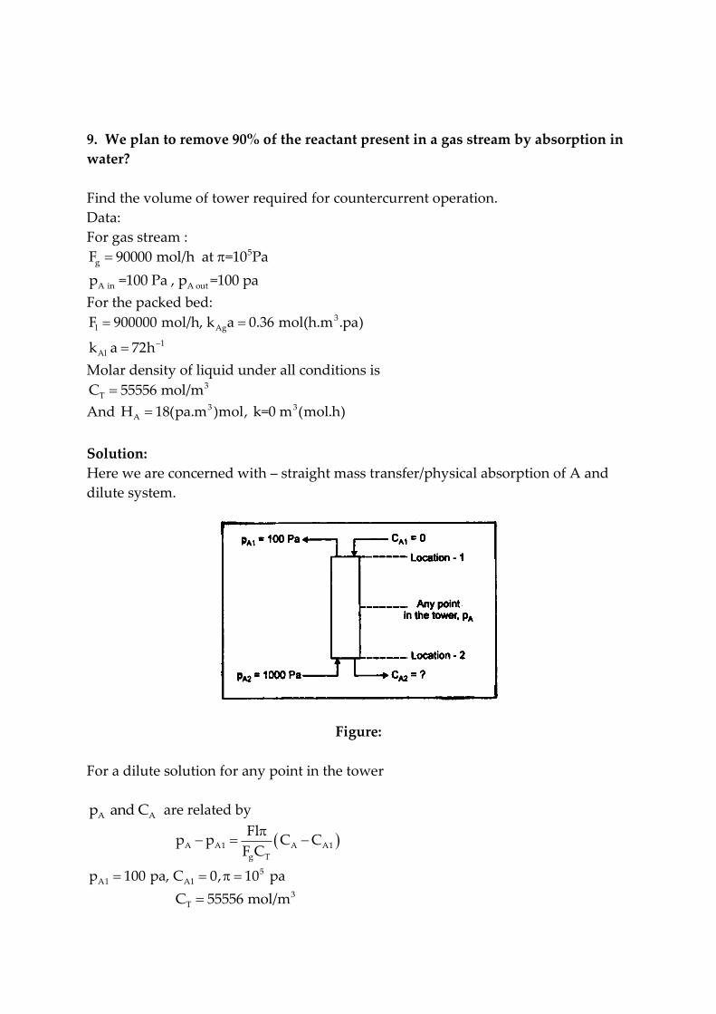
9. We plan to remove 90% of the reactant present in a gas stream by absorption in
water?
Find the volume of tower required for countercurrent operation.
Data:
For gas stream : 5
g
A in A out
F 90000 mol/h at =10 Pa
p =100 Pa , p =100 pa
For the packed bed: 3
l Ag
1Al
F 900000 mol/h, k a 0.36 mol(h.m .pa)
k a 72h
Molar density of liquid under all conditions is 3
TC 55556 mol/m
And 3 3AH 18(pa.m )mol, k=0 m (mol.h)
Solution:
Here we are concerned with – straight mass transfer/physical absorption of A and
dilute system.
Figure:
For a dilute solution for any point in the tower
A A p and C are related by
A A1 A A1
g T
Flp p C C
F C
5A1 A1p 100 pa, C 0, 10 pa
3TC 55556 mol/m

i gF 900000 mol/h, F = 90000 mol/h 5
A A
900000 10p 100 = (C 0)
90000 55556
A Ap 100 18C
A Aor C 0.05556 p 5.5556
The concentration of A in water leaving the tower is given by
A2 A2C 0.05556 p 5.5556
A2 For p 1000 pa
A2
3
C 0.05556(1000) 5.5556
= 50 mol/m
Now select a few values of Ap in addition to A1p and A2p in the tower and determine * *
A A A AC p (p p )
Take :
A A
A
A A
Take : p 550 Pa to p 800 Pa
For p 550 Pa
C 0.05556 p 5.5556
3
AC 0.05556(550) 5.5556 25mol / m
* 3A A A A
*A
* *A A A
p H C , H 18(pa.m ) / mol
p 18 25 450Pa
p p p 550 450 100 Pa
Ap AC *A A AP H C *
A A AP P P
100 0 0 100
550 25 450 100
800 38.89 700 100
1000 50 900 100
Here we have constant Ap so graphical procedure is not required (as is constant
it can be taken out of the integral sign).

Next evaluate AgK a :
-1Ag Al
Ag Ag Al
Ag
1 1 1 k a 0.36mol / 0 k a=72 h
K a k a k a
1 18
0.36 72 2.78 0.25
3.03
K a = 1/3.03=
30.33 mol/(h.m Pa)
The volume of tower is given by
A 2
A1
pg *A
r A A A*Ag A A AP
1000g
A
Ag A 100
5
5
3
F dpV , P P P
K a p P P
F dp
K a p
90000 (1000 100)
10 0.33 10090000
(1000 100)10 0.33 100
24.54 m
10. Repeat the above problem for 3
AH 1.8 Pa m / mol
Solution :
From the solution of previous example.
For any point in the tower, AP and AC are related by
A AC 0.05556 p 5.5556
3A2and C 50 mol/m
Now select few values of Ap in addition to A1p and A2p and determine * *
A A A AC P (p p )
Now 3AH 1.8(P.am )/ mol

For Ap 550 Pa
A A
3A
*A A A
*A A A
C 0.05556 p 5.5556
C 0.05556(550) 5.5556 25 mol/m
p H C 1.8 25 45Pa
p p p 550 45 505 Pa
For Ap 275 Pa
3
A
*A
C 0.05556(275) 5.5556 9.7234 mol/m
p 1.8 9.7234
= 17.5 Pa
For AP 800 Pa
A
3
*A
C 0.5556(8000) 5.5556
= 38.89 mol/m
P 1.8 38.89 = 70 Pa
3 *A A AFor p 1000 Pa, C 50 mol/m and p 90 Pa.
Ap AC *A A AP H C *
A A AP P P
100 0 0 100
275 9.7234 17.5 257.5
550 25 45 505
800 38.89 70 730
1000 50 90 910
Here AP is not constant.
The volume of tower is given by
From Ex. 3.2 : 3AgK 0.33 mol/(h.m .Pa)
A 2
A1
pg A
r ""AP
"" *A Ag A A
F dpV
-r
-r K a (p P )

A 2
A1
p
Ar""
g AP
dpV
F -r
Evaluate the integral on RHS graphically.
A""A
1v / s p
( r ). The area under the curve between Alp and ---- integral and is equal to
r gV / F .
r
g
V
F
= area under curve scale x-axis scale y-axis.
Now evaluate ""Ar for each Ap and tabulate.
For *A a A Ap 100 p , p P 0 and p 100 Pa
"" *A Ag A A Ag A-r K a (p P ) K a P
3 0.33 100=33 mol/(h.m )
"" 3A
11/(-r ) 0.0303 (h.m ) / mol
33
Ap *AP *
A A AP P P ""Ar
100 `0 100 33
275 17.5 257.5 84.975
550 45 505 166.65
1000 90 910 300.3
A""A
1Plot v/s p
(-r )
We have A1 A2: P 100 Pa and p 1000 Pa
Measure the area under the curve between A A1 Ap p 100 Pa and p ------
Refer Figure. 3.3.
------------------

r
g
g 3r 5
VArea scale y-axis scale x-axis
F
0.005 100 = 29.5 7.375
2 17.375 F 7.375 90000
V 6.64 m10
3Volume of tower = 6.64 m
…Ans.
Figure: E.33
11. An undesired impurity is to be removed from air in a counter current tower.
Impurity in inlet air = 0.5% (500 Pa)
Impurity in outlet air = 0.1% (100 Pa)
Flow rates of gas and liquid are :
5 2
g cs
5 2l cs
3Ag
-1Al
F / A 1 10 mol/(h.m )
F / A 10.6 10 mol/(h.m )
k a 0.60 mol/(h.m .Pa)
k a = n0.5 h

Molar density of liquid, assumed constant, is
3
TC = 56000 mol/m
And 3AH 15(Pa.m )/ mol
Calculate the height of tower required.
Solution:
Here we are concerned with – straight mass transfer of A an---------------------
Figure: E 3.4 (a)
For any point in the tower AP and AC are related by
l csA Al A A1
g cs T
(F / A )(p p ) (C C )
(F / A )C
5Al A1p 100 Pa, C 0, -10 Pa
3TC = 56000 mol/m
5l csF / A 10.6 10 mol /
---
A Ap 100 18.928 C
A Aor C 0.05283 p 5.283
… (1)
The concentration of impurity (A) in the water entering the tower A[C 2] is
obtained by using above relation.
A2 A2C 0.05283 p 5.583

We have A2P 500 Pa 3
A2 C 0.05283(500) 5.283 21.132 mol/m
3
AH 15 (Pa.m )/ mol
Now select few values of Ap , determine the corresponding concentration of A
A(C ) in liquid using Equation (1), calculate the equilibrium partial pressure of A, *Ap , corresponding to AC and then calculate *
A A Ap p p , overall gas phase driving
force.
Take
A
A A
3A
*A A A
p 300 Pa
C 0.05283 p 5.283
C 0.05283(300) 5.283 10.566 mol/m
p H C
= 15 10.566 = 158.49 158.5 Pa
*A A Ap p p 300 158.5 141.5 Pa
Ap AC *A A AP H C *
A A AP P P
100 0 0 100
200 5.283 79.24 120.76
300 10.566 158.5 141.5
400 15.849 237.7 162.3
500 21.132 317 183
Here AP is not constant so we will adopt a graphical procedure for the
determination of height of the tower.
We have : A 2
A1
A 2
A1
Pg A
R cs ""AP
P
A
""g cs AP
F dpV h A
r
dph
(F A ) r
3Ag
-1Al
3A
k Ea 0.60mol /(h.m Pa)
k a = 0.5h
H 15(Pa.m ) / mol

A
Ag Ag Al
1 1 H
K a k a K a
1 15
0.6 0.5 1.667 30 31.667
3ag
1 K a = 0.0316 mol/(h.m .Pa)
31.667
Gas film resistance = (1.667/31.667) 100 = 5.26%
Liquid film resistance = (30/31.667) 100= 94.74%
So it is a liquid film controlling process (as major resistance film).
A
""A Ag A *r = K a(p p )
Now evaluate ""Ar for each value of Ap and tabulate.
Ap *A AP P ""
Ar ""A1/( r )
100 100 3.16 0.316
200 120.76 3.82 0.262
300 141.5 4.47 0.224
400 162.3 5.13 1.195
500 183 5.78 0.173
A 2
A1
P
A
""g cs AP
500
A
""A100
dph
(F A ) r
dp
r
= Area under the curve scale y-axis scale x-axis
A""A
1Plot v/s p
(-r ) and measure area under curve between A1p 100 Pa and
A2p 500 Pa.
Refer Figure. E 3.4 (b):
Area under the curve = 1829 2 2mm 18.29 cm

g cs
g cs
g cs
hArea Scaley axis Scale x-axis
(F / A )
h 0.1 10018.29
(F / A ) 2 1
91.45
91.45(F / A ) h
91.45
Height of tower = 91.45 m
… Ans.
Figure E 3.4 (b)
12. We plan to remove about 80% of the A present in a gas stream by absorption
in water containing reactant B. Material B reacts with A as per the following
reaction:
A(g l) + B(l) R(l)
The reaction is extremely rapid so k= .
Determine the height of tower for countercurrent operation using following data.
Data:
The gas and liquid flow rates are:

5 2 5g cs
5 2l cs
3A
F / A 1 10 mol(h.m )at 10 Pa
F / A 7 10 mol(h.m )
H 12.5(Pa.m )mol
TC (molar density of liquid ) = 56000 mol/m3
A
3Ag
-1Al
p in = 100 Pa
k a = 0.32 mol/(h.m .Pa)
k a = 0.10 h
BC = concentration of reactant B in water entering the tower = 800 mol/ 3m . 3 800 mol/m .
Assume that the diffusitivities of A and B in water are the same.
Solution:
A(g l) + B(l) R(l) , k= .
It is extremely rapid reaction (instantaneous reaction)
Here b= 1 (Stoichiometric coefficient of B)
A A2P in p 100Pa
0% of QA is removed from air
A out Al P P 100(1 0.80) 20Pa
Figure: E 3.6

First find B2C with the help of material balance.
B2C is the concentration of B in exit stream from the tower.
For dilute solutions the simplified material balance yields :
l csA Al Bl B
g cs T
(F / A )(p p ) (C C )
(F / A )b C
5 3
Al TP = 20 Pa, =10 Pa, b=1, C 56000mol / m
3
BlC 800mol / m
5 2
l cs
5 2g cs
A B
B A
F / A 7 10 mol(h.m )
F / A 1 10 mol(h.m )
P -20 =10020-12.5 C
or C = 801.6-0.08 P
The above equation relates B AC to p at any point in the tower.
At the bottom of the tower :
TC (molar density of liquid ) = 56000 mol/m3
A A2
A2B2
3B2
p p = 100 Pa
C = 801.6 - 0.08 p
C 801.6 0.08 100 793.6 mol/m
It is given that the reaction is extremely rapid (instantaneous).
To find the appropriate form of rate equation we have to determine whether it is
instantaneous reaction with low or high BC and for this estimate
Ag A Bl Bk a p and k a C / b at both ends of the tower.
Bl AlAs D D (same diffusivit6ies in water)
We have
-1
Al Blk a = k a = 0.10 h
Al Blk a k a

3Agk a = 0.32 mol/(h.m .Pa)
At top of the tower:
3
A Al B Bl
3Ag A
3Bl B
Ag A Bl B
p p 20 Pa, C C 800mol / m
k a p = 0.32 20 = 6.4 mol/(h.m )
k aC 0.10 800 80 mol/(h.m )
b 1 k a p < k a C / b
At bottom of the tower :
3
A A2 B B2
3Ag A
3Bl B
Ag A Bl B
Ag A Bl
p p 100 Pa, C C 793.6 mol / m
k a p = 0.32 100 =32 mol/(h.m )
k aC 0.1 793.16 79.32 mol/(h.m )
b 1At both ends of tower k a p k a C / b
As k p k a we have:
Instantaneous reaction with high BC . Gas phase resistance controls. Reaction zone
is at the interface and so the form of rate equation is
"" "A A Ag Ag A
""A A
r ( r ) a k a k a P
r = 0.32 p
The height of tower is given by
A 2
A1
Pg cs A
""AP
100g cs A
A20
F /A dph =
r
F /A dp=
(0.32) p
5
5
1 10 ln (100/20)1 10 0.32
= 5.03 m
Height of tower for counter current operation = 5.03 m
….(Ans).

13. Derive the rate expression for instantaneous Reaction (…with low CB) :
For low BC we have the situation as shown in Fig. 2.4. Here an element of liquid
contains either A or B not both. Consequently, reaction will occur at a plane
between A- containing and B- containing liquid (in the liquid film). As reactants A
and B must diffuse to this reaction plane for reaction to occur, the general rate will
be decided by ithe rate of diffusion A and B to this reaction plane.
Figure: Concentration profiles of reactants for an infinitely fast irreversible
reaction for case A- low BC - (two-film theory)
At steady state, the flow rate of B toward the reaction zone will be b times that
of A. Thus the rate of disappearance of A and B based on the unit interfacial surface
are given by ""
"" BA Ag A Ai Al Ai B 0
r Xo Xor k (p p ) = k (C 0) (C ) ...(2.17)
b X Xo x
----------------------------- --------------------------
A through gas film A through liquid film B through liuqid film
Where , Agk gas film mass transfer coefficient for A, 2mol /(m .Pa.s)
Alk liquid film mass transfer coefficient for A, 3 2m liqid/(m surface.s)
Blk - liquid film mass transfer coefficient for B.
The liquid side coefficients are based of flow through the whole will of thickness xo .
The equilibrium relationship between A Ap and C at the interface is given by Henry’s
law

Ai A Aip H C
According to the two-film theory the liquid phase mass transfer coefficients
for A and B are given by
Al BlAl Bl
o o
D Dk and k =
x x
Al oAl Al
Bl Bl o Bl
D xk D =
k D /x D …(2.19)
Now we will eliminate the unknowns x, ox , AiC , and Aip from the above
equations to obtain desired rate equation is terms of known quantities.
From Equation (2.17) we have
""A Ag A Air k (P P ) ""A
A Ai
Ag
rP P
k
Dividing the above equations by AH gives
""A A Ai
A Ag A A
r P P
H k H H
…(2.20)
"" oA Al Ai
xr k (C 0)
x
""oA
Ai
Al
xrC
k x
…(2.12)
Also, o oBlAl Ai B
o
x xkk (C 0) (C 0)
x b x x
Ai Bl B
Al o
C k C
x b k (x x)
BlAi o Ai B
Al
BlAi o B Ai
Al
kC x C x C x
b k
kC x C C x
b k

BlB Ai
Alo
Ai
kC C
b kx
x C
..(2.22)
Using Equation (2.22) to substitute for ox / x , Equation (2.21) becomes
"A Bl
Ai B Ai
Al Al
r kC C C
k b k
"A Bl
B Ai
Al Al
r kC C
k b k
…(2.23)
Henry’s law is
Ai A AiP H C
AiAi
A
PC
H …(2.24)
Substituting AiC form Equation (2.24) into Equation (2.23) yields
"A Bl Ai
B
Al Al A
r k P C
k b k H
…(2.25)
Adding Equations (2.20) and (2.25) gives
"" ""A A A Ai Bl Ai
B
Ag Al A A Al A
r r P P k P C
H k k H H b k H
"" A BlA B
Ag Al A Al
1 1 P kr C
H k k H b k
….(2.26)
We have,
Ai oAl
Bl Bl o
Bl Bl
Al Al
D / xk
k D / x
k D
k D

Replacing Bl Al Bl Alk / k by D / D in Equation (2.26) gives
"" A Bl BA
A Ag Al A Al
1 1 P D Cr
H k k H D b
Bl B A
"" A Al AA
A Ag Al
D C P
1 dN D b Hr
1 1S dtH k k
….(2.27)
…….for Bl BAg A
k Ck p
b
…. Reaction takes place within the liquid film ……….liquid film controls.
14. Derive the rate expression for slow reaction with respect to mass transfer?
Here all reaction occurs in the main body of the liquid with the liquid film still
offering a resistance to transfer of A into the main body of liquid. So the gas film,
the liquid film and the main body of he liquid act as resistance in series and all the
resistances will enter into the overall rate expression.
For these three steps we can write:
(a) Gas film: ""A Ag A Air k a(p p )
(b) Liquid film: ""A Al Ai Ar k a(C C )
(c) Main body of liquid: AAl A B
l
1 dNr kC C
V dt
but ""A r Al l( r )V ( r )V
"" lA Al
r
V( r ) ( r )
V
""A A B l l l r (-r ) kC C f , f V / V
""A
A Ai A
A
rp p ...step (a) ......... dividing by H we get
k a

""A Ai AA
Ai Ai A Ai
Ag A A A
""A
Ai A
Al
""A
A
B l
p p prC , as p H C
H k a H H H
-r C C ......... step (b)
k a
-r C ......... step (c)
k C f
Adding Equations gives
"" A AA Ai Ai Al
A Ag Al B l A A
"" AA
A Ag Al B l A
""A A
A Ag Al B l
p p1 1 1( r ) C C C
H k a k a k C f H H
p1 1 1 ( r ) .
H k a k a k C f H
1 1 1 ( r ) p
H k a k a k C f
Figure: Slow reaction (Case G) – showing liquid-film resistance.
15. Derive the equation for volume of tower required for mass transfer with
reaction?
Mass Transfer + Reaction in a Countercurrent Tower – Plug flow G + Plug flow L:

The material balance for a differential element of tower (absorber – reactor)
volume dVr is
‘A’ lost by gas = 1
(' B' lost by liquid)b
1 2
lg A B B
FF dY (X X )
b
Composition at any point in the tower from point 1 is given by
lg A A1 B1 B
FF (Y Y ) (X X )
b
For dilute systems (for the case where all participants in the reaction are dilute)
U U Tp and C C .
dilute
AA A U
U
dpdY d(p / p )
p
and CU CT dXA = dCA/CT
Equation for dilute systems simplifies to
g l
A A
T
F Fdp dC
bC
Integrating for the whole tower gives
g l
A2 A1 B1 B2
T
F F(p p ) (C C )
bC
Integrating equation from point 1 to any point in the tower gives
g l
A A1 B1 B
T
F F(p p ) (C C )
bC

The volume of tower or the height of tower is found by combining the
material balance and the rate equation for a differential element of tower volume
dVr.
A reacted in element - A reacted in element -
from material balance from rate expression
disappearance of A 1 ('A' lost by gas) = (B lost by liquid) =
by reactionb
""l Bg A A r
"" ""A A
FdX F dY r dV
b
But, (-r ) (-r )a
""A(-r ) is the rate based on unit interfacial area.
With ""A(-r ) = ""
A(-r ) a, Equation becomes
""l Bg A A r
FdX F dY r a dV
b
This on integration gives,
A2 B1
A1 B2
Y X
A l Br cs g " "
A AY X
dY F dXV hA F
( r )a b ( r )a
For dilute systems,
g " "l B
A A r A r
T
F FdCdp ( r )dV ( r )a dV
bC
Integrating equation, we get
A 2 B1
A1 B2
p Cg A l B
r cs " "A T Ap C
F dp F dCV hA
( r )a bC ( r )a
******************
Top Related