


Languages
Pages
Legal


8/31/2015 Centrifugal Compressor Design and Rerating in Turbochargers
http://articles.compressionjobs.com/articles/engineering/3458centrifugalcompressordesignreratingturbochargers?tmpl=component&print=1&page= 1/8
Centrifugal Compressor Design and Rerating in TurbochargersWritten by Leonid Moroz
Monday, 05 April 2010 08:17
Leonid Moroz
SoftInWay, Inc.Burlington, MA 01803, USA
Sergey Gnezdilov JSC «SKBT» Penza, 440034, Russia
Contact author: Leonid Moroz, [email protected]
Abstract
Special numerical research is carried out to study the effects of different centrifugal compressor design and reratingstrategies needed for flow path components standardization during manufacturing and retrofitting processes inturbochargers.
Experimental data vs calculation results comparisons for several centrifugal compressor designs are used to confirmthe validity of calculations in predicting performance and operating range.
Numerical calculations allowed to estimate the influence of impeller and vaned diffuser geometry modificationsacceptable within selected constraints.
The strategy gives possibility to design highly efficient centrifugal compressors or use existing centrifugal compressorflow paths instead of new ones that can be created by
trimming the impeller wheel at trailing edgevarying impeller blade heights at leading and trailing edgesmodifying vaned diffuser height and its stagger angle
Accurate offdesign flow predictions are made to find stable operation ranges of upgraded centrifugal compressorflow paths.
The described study is carried out in collaboration with large turbochargers’ manufacturer engaged in locomotive,marine, heavyduty trucks, drilling rigs, power, and pipeline stations appliances.
Nomenclature
8/31/2015 Centrifugal Compressor Design and Rerating in Turbochargers
http://articles.compressionjobs.com/articles/engineering/3458centrifugalcompressordesignreratingturbochargers?tmpl=component&print=1&page= 2/8
D1, D2 Impeller inlet/outlet diameter
l1, l2 Impeller inlet/outlet blade height
η Compressor efficiency
ω Rotational speed
πC Compressor pressure ratio
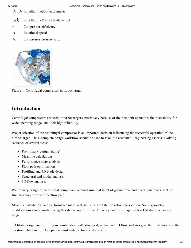
Figure 1. Centrifugal compressor in turbocharger
Introduction
Centrifugal compressors are used in turbochargers extensively because of their smooth operation, their capability forwide operating range, and their high reliability.
Proper selection of the centrifugal compressor is an important decision influencing the successful operation of theturbocharger. Thus, complete design workflow should be used to take into account all engineering aspects involvingsequence of several steps:
Preliminary design (sizing)Meanline calculationsPerformance maps analysisFlow path optimizationProfiling and 3D blade designStructural and modal analysis3D flow analysis
Preliminary design of centrifugal compressor requires minimal input of geometrical and operational constraints tofind acceptable sizes of the flow path.
Meanline calculations and performance maps analysis is the next step to refine the solution. Some geometrymodifications can be made during this step to optimize the efficiency and meet required level of stable operatingrange.
3D blade design and profiling in combination with structural, modal and 3D flow analyses give the final answer to thequestion what kind of flow path is most suitable for specific needs.
8/31/2015 Centrifugal Compressor Design and Rerating in Turbochargers
http://articles.compressionjobs.com/articles/engineering/3458centrifugalcompressordesignreratingturbochargers?tmpl=component&print=1&page= 3/8
Centrifugal compressor rerating is often required to meet new design flow rate or head. These changes, in many cases,need the compressor to be "redesigned".
It includes anything from a simple speed change to trimming of impellers. In the case of vaned diffuser being used inthe compressor, the compressor surge margin is greatly reduced because of changes in suction pressures [1]. This isdue to the flow angle at the exit of the impeller having a large incidence angle on the diffuser blade.
In this article some ways to change the head and flow of existing compressors are discussed and investigated.Compressor rerating requires an indepth knowledge of the compressor and its components.
The requirements for a different head at approximately just the same flow would require changes in machine speedand, in some cases, the trimming of the wheels.
It is also known that trimming the compressor wheels would also reduce head produced. A speed increase after thewheels have been trimmed would then increase the head delivered at a higher flow [2].
Experimental Test Facility
Centrifugal compressor performance was evaluated using an experimental test facility. Centrifugal compressor wasdriven by the axial turbine stage utilizing the power of exhaust gases supplied by converted aeroderivative combustionchamber. This method was used because of high power input level that has been needed for driving the centrifugalcompressor in selected turbocharger.
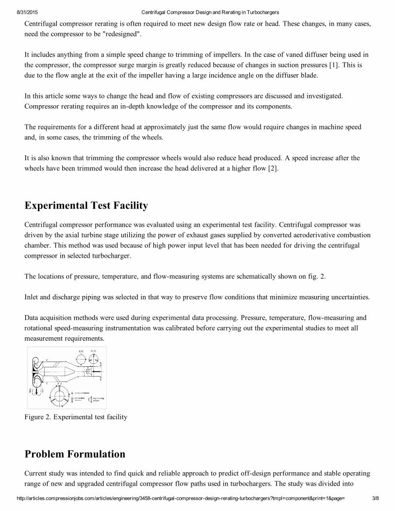
The locations of pressure, temperature, and flowmeasuring systems are schematically shown on fig. 2.
Inlet and discharge piping was selected in that way to preserve flow conditions that minimize measuring uncertainties.
Data acquisition methods were used during experimental data processing. Pressure, temperature, flowmeasuring androtational speedmeasuring instrumentation was calibrated before carrying out the experimental studies to meet allmeasurement requirements.
Figure 2. Experimental test facility
Problem Formulation
Current study was intended to find quick and reliable approach to predict offdesign performance and stable operatingrange of new and upgraded centrifugal compressor flow paths used in turbochargers. The study was divided into
8/31/2015 Centrifugal Compressor Design and Rerating in Turbochargers
http://articles.compressionjobs.com/articles/engineering/3458centrifugalcompressordesignreratingturbochargers?tmpl=component&print=1&page= 4/8
several phases:
Validation of centrifugal compressor flow prediction tool using performance data obtained during experimentalstudies of several compressor flow pathsPerformance and stable operating range predictions for different alternative centrifugal compressor flow pathmodifications
Preliminary Design
The first step of the study was to carry out the preliminary design from the ground and find optimal solution usinggeometrical constraints and operational boundary conditions close to values of design parameters used in centrifugalcompressor (TK23 series) manufactured by JSC «SKBT».
Preliminary design in 1D inverse problem formulation was used to find the solution taking into account specifieddesign conditions (ω= 32000 rpm ,πC = 3.5 ).
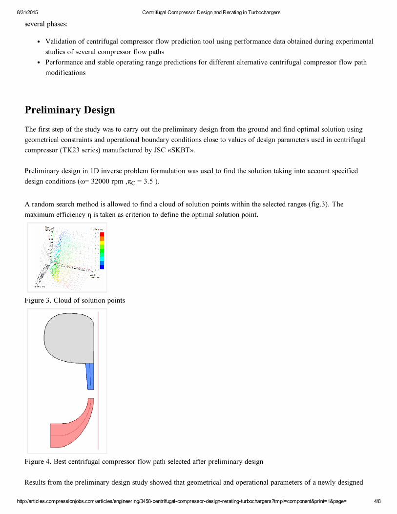
A random search method is allowed to find a cloud of solution points within the selected ranges (fig.3). Themaximum efficiency η is taken as criterion to define the optimal solution point.
Figure 3. Cloud of solution points
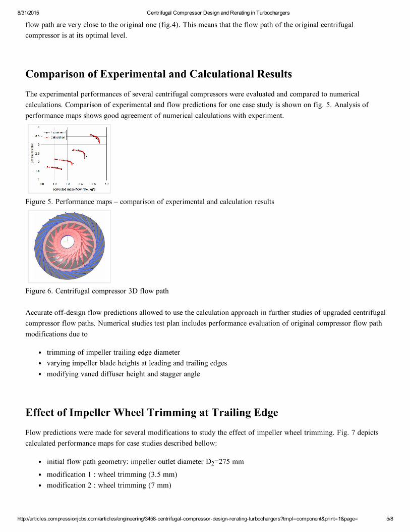
Figure 4. Best centrifugal compressor flow path selected after preliminary design
Results from the preliminary design study showed that geometrical and operational parameters of a newly designed
8/31/2015 Centrifugal Compressor Design and Rerating in Turbochargers
http://articles.compressionjobs.com/articles/engineering/3458centrifugalcompressordesignreratingturbochargers?tmpl=component&print=1&page= 5/8
flow path are very close to the original one (fig.4). This means that the flow path of the original centrifugalcompressor is at its optimal level.
Comparison of Experimental and Calculational Results
The experimental performances of several centrifugal compressors were evaluated and compared to numericalcalculations. Comparison of experimental and flow predictions for one case study is shown on fig. 5. Analysis ofperformance maps shows good agreement of numerical calculations with experiment.
Figure 5. Performance maps – comparison of experimental and calculation results
Figure 6. Centrifugal compressor 3D flow path
Accurate offdesign flow predictions allowed to use the calculation approach in further studies of upgraded centrifugalcompressor flow paths. Numerical studies test plan includes performance evaluation of original compressor flow pathmodifications due to
trimming of impeller trailing edge diametervarying impeller blade heights at leading and trailing edgesmodifying vaned diffuser height and stagger angle
Effect of Impeller Wheel Trimming at Trailing Edge
Flow predictions were made for several modifications to study the effect of impeller wheel trimming. Fig. 7 depictscalculated performance maps for case studies described bellow:
initial flow path geometry: impeller outlet diameter D2=275 mm
modification 1 : wheel trimming (3.5 mm)modification 2 : wheel trimming (7 mm)
8/31/2015 Centrifugal Compressor Design and Rerating in Turbochargers
http://articles.compressionjobs.com/articles/engineering/3458centrifugalcompressordesignreratingturbochargers?tmpl=component&print=1&page= 6/8
Figure 7. Effect of impeller wheel trimming at trailing edge
Effect of Impeller Inlet Height Variation
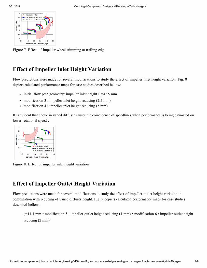
Flow predictions were made for several modifications to study the effect of impeller inlet height variation. Fig. 8depicts calculated performance maps for case studies described bellow:
initial flow path geometry: impeller inlet height l1=47.5 mm
modification 3 : impeller inlet height reducing (2.5 mm)modification 4 : impeller inlet height reducing (5 mm)
It is evident that choke in vaned diffuser causes the coincidence of speedlines when performance is being estimated onlower rotational speeds.
Figure 8. Effect of impeller inlet height variation
Effect of Impeller Outlet Height Variation
Flow predictions were made for several modifications to study the effect of impeller outlet height variation incombination with reducing of vaned diffuser height. Fig. 9 depicts calculated performance maps for case studiesdescribed bellow:
2=11.4 mm • modification 5 : impeller outlet height reducing (1 mm) • modification 6 : impeller outlet height
reducing (2 mm)
8/31/2015 Centrifugal Compressor Design and Rerating in Turbochargers
http://articles.compressionjobs.com/articles/engineering/3458centrifugalcompressordesignreratingturbochargers?tmpl=component&print=1&page= 7/8
Figure 9. Effect of impeller outlet height variation
Effect of Vaned Diffuser Stager Angle Variation
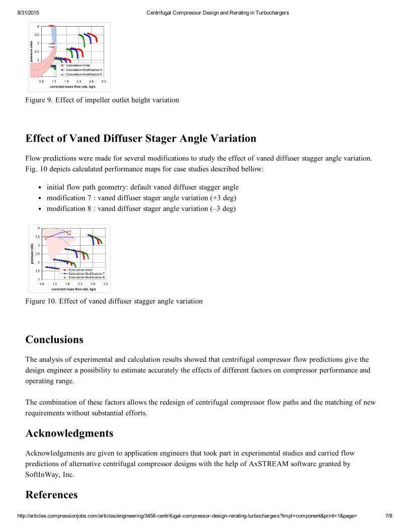
Flow predictions were made for several modifications to study the effect of vaned diffuser stagger angle variation.Fig. 10 depicts calculated performance maps for case studies described bellow:
initial flow path geometry: default vaned diffuser stagger anglemodification 7 : vaned diffuser stager angle variation (+3 deg)modification 8 : vaned diffuser stager angle variation (–3 deg)
Figure 10. Effect of vaned diffuser stagger angle variation
Conclusions
The analysis of experimental and calculation results showed that centrifugal compressor flow predictions give thedesign engineer a possibility to estimate accurately the effects of different factors on compressor performance andoperating range.
The combination of these factors allows the redesign of centrifugal compressor flow paths and the matching of newrequirements without substantial efforts.
Acknowledgments
Acknowledgements are given to application engineers that took part in experimental studies and carried flowpredictions of alternative centrifugal compressor designs with the help of AxSTREAM software granted bySoftInWay, Inc.
References

8/31/2015 Centrifugal Compressor Design and Rerating in Turbochargers
http://articles.compressionjobs.com/articles/engineering/3458centrifugalcompressordesignreratingturbochargers?tmpl=component&print=1&page= 8/8
1. Aungier Ronald H., "Centrifugal compressors: a strategy for aerodynamic design and analysis", New York,ASME Press, 2000.
2. Watson N. Turbocharging the Internal Combustion Engine, John Wiley & Sons Inc, 1982.
Top Related