


Languages
Pages
Legal


CCNA v3.0 Semester 3
CCNA v3.0Module 1
Introduction to Classless Routing
CCNA v3.0 Semester 3 2
What is VLSM?
A Variable Length Subnet Mask (VLSM) is a means of allocating IP addressing resources to subnets according to their individual need rather than some general network-wide rule.
VLSM allows an organization to use more than one subnet mask within the same network address space. It is often referred to as ‘subnetting a subnet’, and can be used to maximize addressing efficiency.
Large subnets are created for addressing LANs and small subnets are created for WAN links (a 30 bit mask is used to create subnets with only two host).
CCNA v3.0 Semester 3 3
Subnetting vs. VLSM
• Subnetting allows you to divide big networks into smaller, equal-sized slices.
• VLSM allows you to divide big networks into smaller, different-sized slices. This enables you to make maximum use of your valuable IP address space.
• So basically, you are now utilizing subnet masks in the same IP address space.
CCNA v3.0 Semester 3 4
Routing Protocols Supporting VLSM
• RIP v2
• EIGRP
• OSPF
CCNA v3.0 Semester 3 5
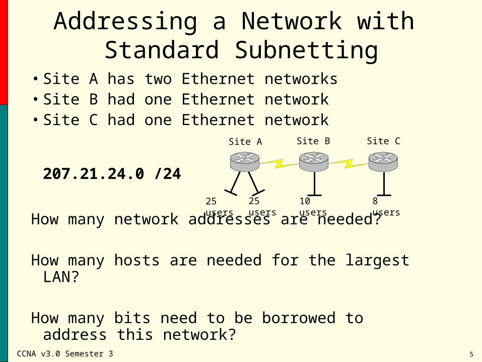
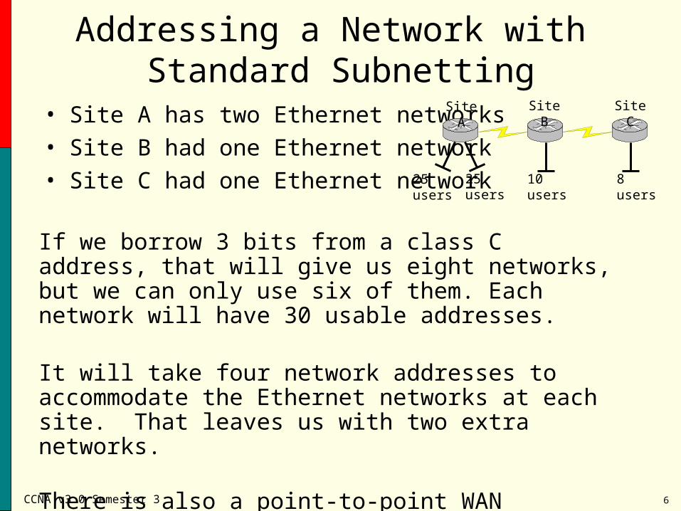
Addressing a Network with Standard Subnetting
• Site A has two Ethernet networks• Site B had one Ethernet network• Site C had one Ethernet network
207.21.24.0 /24
How many network addresses are needed?
How many hosts are needed for the largest LAN?
How many bits need to be borrowed to address this network?
Site A Site B Site C
25 users 25 users 10 users 8 users
CCNA v3.0 Semester 3 6
Addressing a Network with Standard Subnetting
• Site A has two Ethernet networks• Site B had one Ethernet network• Site C had one Ethernet network
Site A Site B Site C
25 users 25 users 10 users 8 users
If we borrow 3 bits from a class C address, that will give us eight networks, but we can only use six of them. Each network will have 30 usable addresses.
It will take four network addresses to accommodate the Ethernet networks at each site. That leaves us with two extra networks.
There is also a point-to-point WAN connection between each site. These two connections will take up the remaining two networks.
CCNA v3.0 Semester 3 7
Addressing a Network with Standard Subnetting
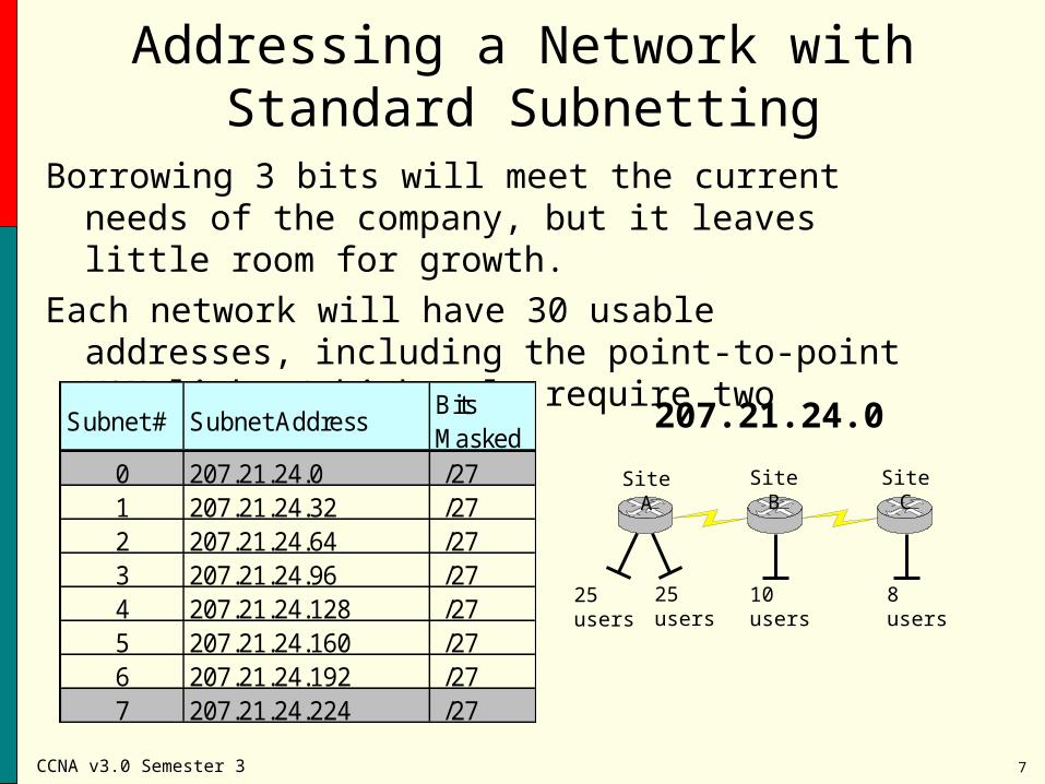
Borrowing 3 bits will meet the current needs of the company, but it leaves little room for growth.
Each network will have 30 usable addresses, including the point-to-point WAN links (which only require two addresses).
Site A Site B Site C
25 users 25 users 10 users 8 users
Subnet # Subnet AddressBits Masked
0 207.21.24.0 /271 207.21.24.32 /272 207.21.24.64 /273 207.21.24.96 /274 207.21.24.128 /275 207.21.24.160 /276 207.21.24.192 /277 207.21.24.224 /27
207.21.24.0
CCNA v3.0 Semester 3 8
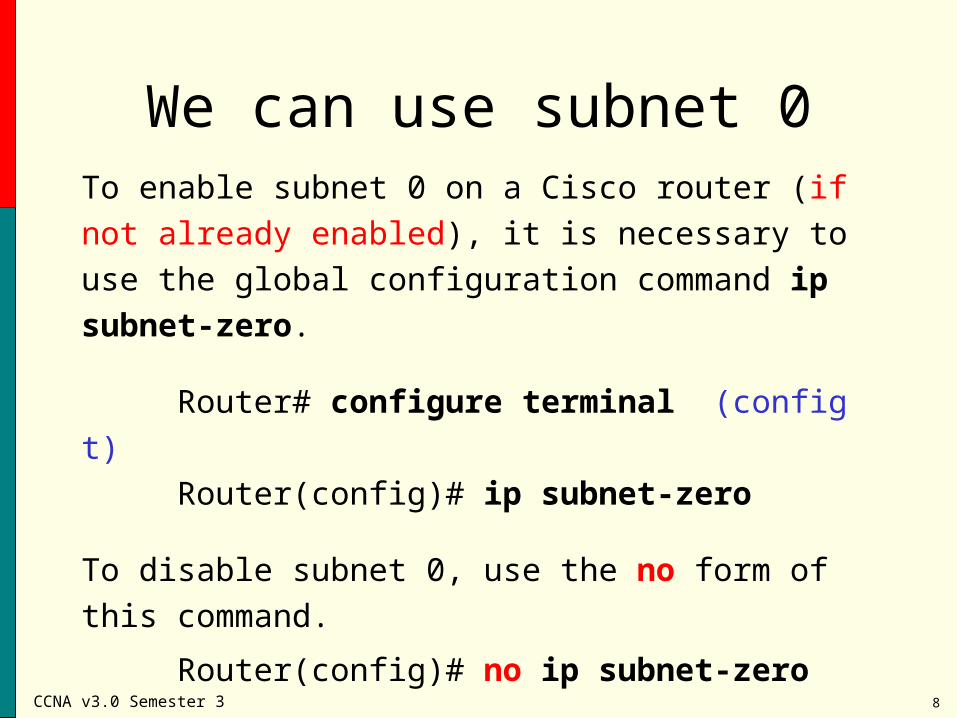
We can use subnet 0To enable subnet 0 on a Cisco router (if not already
enabled), it is necessary to use the global configuration
command ip subnet-zero.
Router# configure terminal (config t)
Router(config)# ip subnet-zero
To disable subnet 0, use the no form of this command.
Router(config)# no ip subnet-zero
CCNA v3.0 Semester 3 9
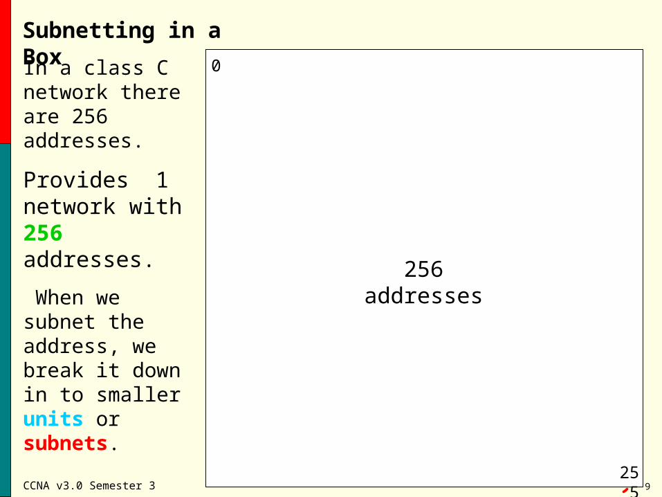
Subnetting in a Box
0
255
In a class C network there are 256 addresses.
Provides 1 network with 256 addresses.
When we subnet the address, we break it down in to smaller units or subnets.
Subnet mask: 255.255.255.0
256 addresses
CCNA v3.0 Semester 3 10
Subnetting in a Box
0
255
128
127
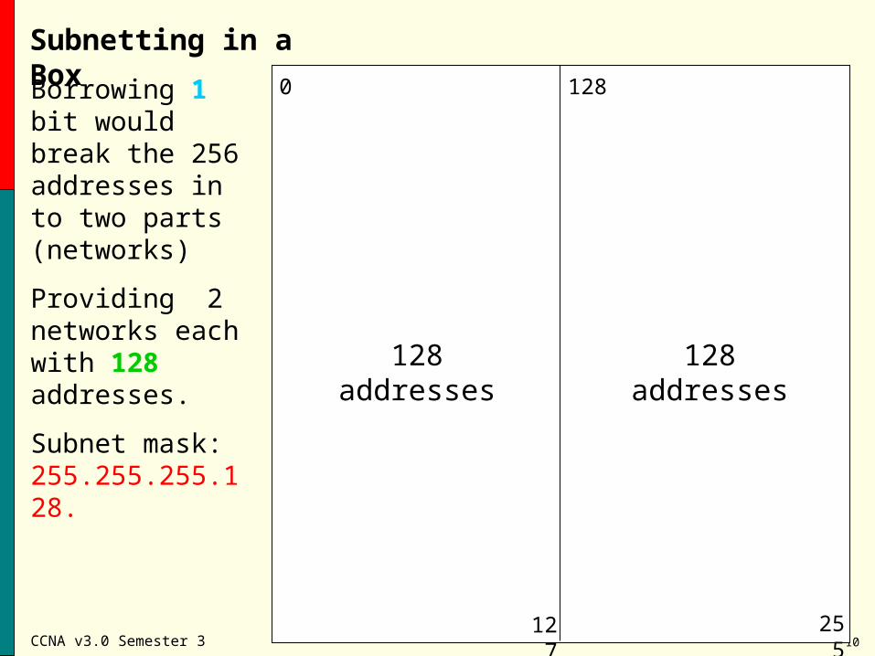
Borrowing 1 bit would break the 256 addresses in to two parts (networks)
Providing 2 networks each with 128 addresses.
Subnet mask: 255.255.255.128.
128 addresses 128 addresses
CCNA v3.0 Semester 3 11
Subnetting in a Box
0
255
128
127
64
63
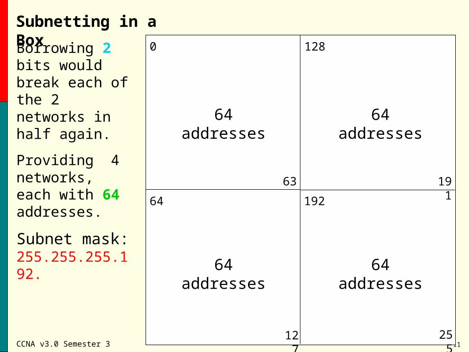
Borrowing 2 bits would break each of the 2 networks in half again.
Providing 4 networks, each with 64 addresses.
Subnet mask: 255.255.255.192.
64 addresses
64 addresses
64 addresses
64 addresses
192
191
CCNA v3.0 Semester 3 12
Subnetting in a Box
0
255
128
127
64 192
63 191
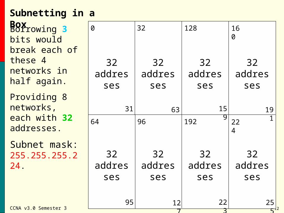
Borrowing 3 bits would break each of these 4 networks in half again.
Providing 8 networks, each with 32 addresses.
Subnet mask: 255.255.255.224.
32addresses
32addresses
31
32
32addresses
32addresses
95
96
32addresses
32addresses
159
160
32addresses
32addresses
223
224
CCNA v3.0 Semester 3 13
Subnetting in a Box
0
255
128
127
64 192
63 191
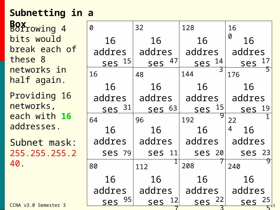
Borrowing 4 bits would break each of these 8 networks in half again.
Providing 16 networks, each with 16 addresses.
Subnet mask: 255.255.255.240.
31
32
95
96
159
160
223
224
16addresses
16addresses
16addresses
16addresses
16addresses
16addresses
16addresses
16addresses
16addresses
16addresses
16addresses
16addresses
16addresses
16addresses
16addresses
16addresses
16
15
48
47
144
143
176
175
80
79
112
111
208
207
240
239
CCNA v3.0 Semester 3 14
Addressing a Network Using VLSM
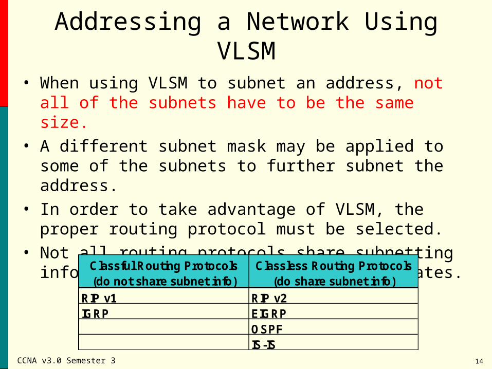
• When using VLSM to subnet an address, not all of the subnets have to be the same size.
• A different subnet mask may be applied to some of the subnets to further subnet the address.
• In order to take advantage of VLSM, the proper routing protocol must be selected.
• Not all routing protocols share subnetting information in their routing table updates.
Classful Routing Protocols(do not share subnet info)
Classless Routing Protocols(do share subnet info)
RIP v1 RIP v2IGRP EIGRP
OSPFIS-IS
CCNA v3.0 Semester 3 15
Addressing a Network Using VLSM
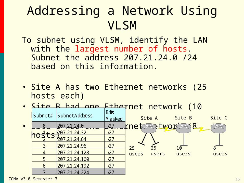
To subnet using VLSM, identify the LAN with the largest number of hosts. Subnet the address 207.21.24.0 /24 based on this information.
• Site A has two Ethernet networks (25 hosts each)• Site B had one Ethernet network (10 hosts)• Site C had one Ethernet network (8 hosts)
Site A Site B Site C
25 users 25 users 10 users 8 users
Subnet # Subnet AddressBits Masked
0 207.21.24.0 /271 207.21.24.32 /272 207.21.24.64 /273 207.21.24.96 /274 207.21.24.128 /275 207.21.24.160 /276 207.21.24.192 /277 207.21.24.224 /27
CCNA v3.0 Semester 3 16
Addressing a Network Using VLSM
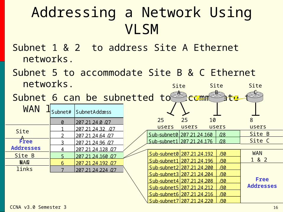
Subnet 1 & 2 to address Site A Ethernet networks.
Subnet 5 to accommodate Site B & C Ethernet networks.
Subnet 6 can be subnetted to accommodate the WAN links.Site A Site B Site C
25 users 25 users 10 users 8 users
Free Addresses
Site A
Subnet # Subnet Address
0 207.21.24.0 /271 207.21.24.32 /272 207.21.24.64 /273 207.21.24.96 /274 207.21.24.128 /275 207.21.24.160 /276 207.21.24.192 /277 207.21.24.224 /27
Site B & C
Sub-subnet 0 207.21.24.160 /28Sub-subnet 1 207.21.24.176 /28
Site BSite C
Subnet # Subnet Address
0 207.21.24.0 /271 207.21.24.32 /272 207.21.24.64 /273 207.21.24.96 /274 207.21.24.128 /275 207.21.24.160 /276 207.21.24.192 /277 207.21.24.224 /27
WAN links
Sub-subnet 0 207.21.24.192 /30Sub-subnet 1 207.21.24.196 /30Sub-subnet 2 207.21.24.200 /30Sub-subnet 3 207.21.24.204 /30Sub-subnet 4 207.21.24.208 /30Sub-subnet 5 207.21.24.212 /30Sub-subnet 6 207.21.24.216 /30Sub-subnet 7 207.21.24.220 /30
Free Addresses
WAN 1 & 2
Subnet # Subnet Address
0 207.21.24.0 /271 207.21.24.32 /272 207.21.24.64 /273 207.21.24.96 /274 207.21.24.128 /275 207.21.24.160 /276 207.21.24.192 /277 207.21.24.224 /27
CCNA v3.0 Semester 3 17
Addressing a Network Using VLSM
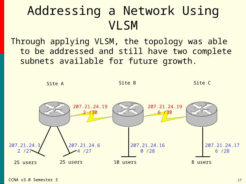
Through applying VLSM, the topology was able to be addressed and still have two complete subnets available for future growth.
Site A Site B Site C
25 users 25 users 10 users 8 users
207.21.24.32 /27 207.21.24.64 /27 207.21.24.160 /28
207.21.24.176 /28
207.21.24.192 /30
207.21.24.196 /30
CCNA v3.0 Semester 3 18
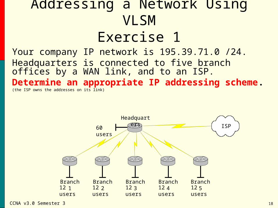
Addressing a Network Using VLSMExercise 1
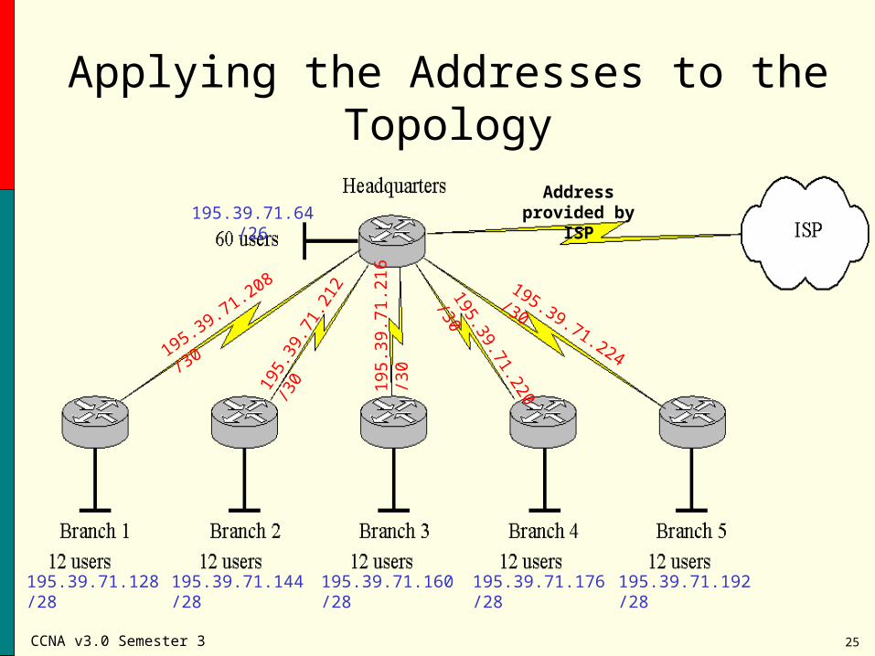
Your company IP network is 195.39.71.0 /24. Headquarters is connected to five branch offices by a WAN link, and to an ISP. Determine an appropriate IP addressing scheme. (the ISP owns the addresses on its link)
Headquarters
Branch 1
60 users
12 users 12 users 12 users 12 users 12 usersBranch 2 Branch 3 Branch 4 Branch 5
ISP
CCNA v3.0 Semester 3 19
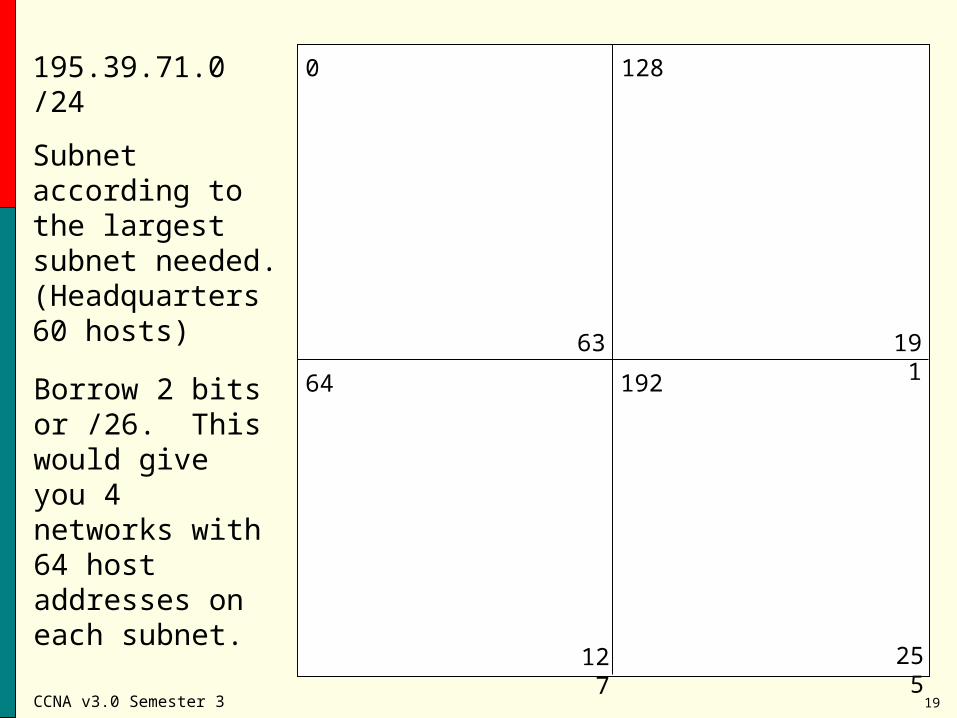
195.39.71.0 /24
Subnet according to the largest subnet needed. (Headquarters 60 hosts)
0
255
128
127
64 192
63 191
Borrow 2 bits or /26. This would give you 4 networks with 64 host addresses on each subnet.
CCNA v3.0 Semester 3 20
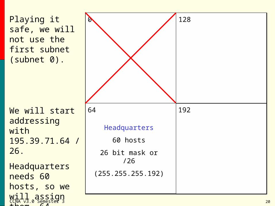
Playing it safe, we will not use the first subnet (subnet 0).
0
64
128
192We will start addressing with 195.39.71.64 /26.
Headquarters needs 60 hosts, so we will assign them .64 - .127.
Headquarters
60 hosts
26 bit mask or /26
(255.255.255.192)
CCNA v3.0 Semester 3 21
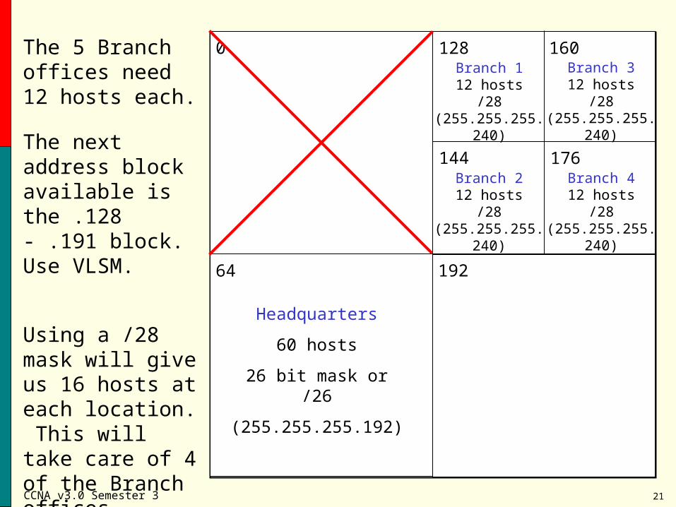
The 5 Branch offices need 12 hosts each.
0
64
128
192
The next address block available is the .128 - .191 block. Use VLSM.
Headquarters
60 hosts
26 bit mask or /26
(255.255.255.192)
Using a /28 mask will give us 16 hosts at each location. This will take care of 4 of the Branch offices.
160
144 176
Branch 112 hosts
/28(255.255.255.240)
Branch 212 hosts
/28(255.255.255.240)
Branch 312 hosts
/28(255.255.255.240)
Branch 412 hosts
/28(255.255.255.240)
CCNA v3.0 Semester 3 22
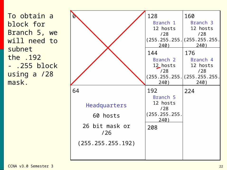
To obtain a block for Branch 5, we will need to subnet the .192 - .255 block using a /28 mask.
0
64
128
192
Headquarters
60 hosts
26 bit mask or /26
(255.255.255.192)
160
144 176
Branch 112 hosts
/28(255.255.255.240)
Branch 212 hosts
/28(255.255.255.240)
Branch 312 hosts
/28(255.255.255.240)
Branch 412 hosts
/28(255.255.255.240)
224
208
Branch 512 hosts
/28(255.255.255.240)
CCNA v3.0 Semester 3 23
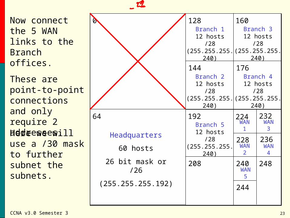
Now connect the 5 WAN links to the Branch offices.
These are point-to-point connections and only require 2 addresses.
0
64
128
192
Here we will use a /30 mask to further subnet the subnets.
Headquarters
60 hosts
26 bit mask or /26
(255.255.255.192)
160
144 176
Branch 112 hosts
/28(255.255.255.240)
Branch 212 hosts
/28(255.255.255.240)
Branch 312 hosts
/28(255.255.255.240)
Branch 412 hosts
/28(255.255.255.240)
224
208
Branch 512 hosts
/28(255.255.255.240)
232
228 236
WAN 1
WAN 2
WAN 3
WAN 4
248
244
WAN 5
240
CCNA v3.0 Semester 3 24
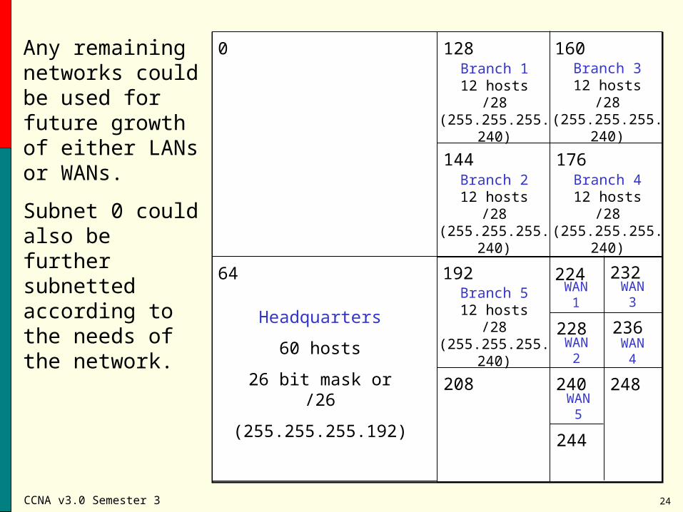
Any remaining networks could be used for future growth of either LANs or WANs.
Subnet 0 could also be further subnetted according to the needs of the network.
0
64
128
192
Headquarters
60 hosts
26 bit mask or /26
(255.255.255.192)
160
144 176
Branch 112 hosts
/28(255.255.255.240)
Branch 212 hosts
/28(255.255.255.240)
Branch 312 hosts
/28(255.255.255.240)
Branch 412 hosts
/28(255.255.255.240)
224
208
Branch 512 hosts
/28(255.255.255.240)
232
228 236
WAN 1
WAN 2
WAN 3
WAN 4
248
244
WAN 5
240
CCNA v3.0 Semester 3 25
Address provided by ISP195.39.71.64 /26
195.39.71.128 /28 195.39.71.144 /28 195.39.71.160 /28 195.39.71.176 /28 195.39.71.192 /28
195.39.71.208 /3019
5.39
.71.
212
/30
195.
39.7
1.21
6 /3
0
195.39.71.220 /30
195.39.71.224 /30
Applying the Addresses to the Topology
CCNA v3.0 Semester 3 26
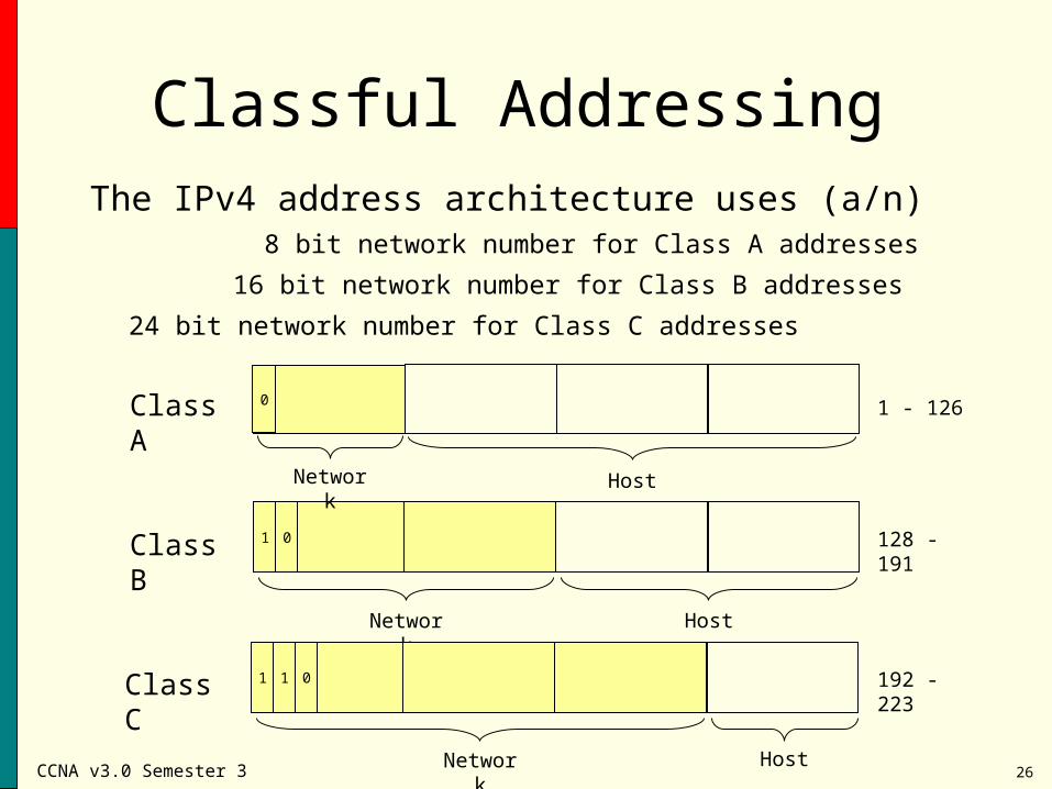
Classful AddressingThe IPv4 address architecture uses (a/n)
8 bit network number for Class A addresses
16 bit network number for Class B addresses
24 bit network number for Class C addresses
1 - 126
128 - 191
192 - 223
Class B
Network Host
1 0
Class C
Network Host
1 1 0
Class A
Network Host
0
CCNA v3.0 Semester 3 27
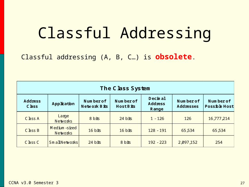
Classful Addressing
Classful addressing (A, B, C…) is obsolete.
Address Class
ApplicationNumber of
Network BitsNumber of Host Bits
Decimal Address Range
Number of Addresses
Number of Possible Host
Class ALarge
Networks8 bits 24 bits 1 - 126 126 16,777,214
Class BMedium-sized
Networks16 bits 16 bits 128 - 191 65,534 65,534
Class C Small Networks 24 bits 8 bits 192 - 223 2,097,152 254
The Class System
CCNA v3.0 Semester 3 28
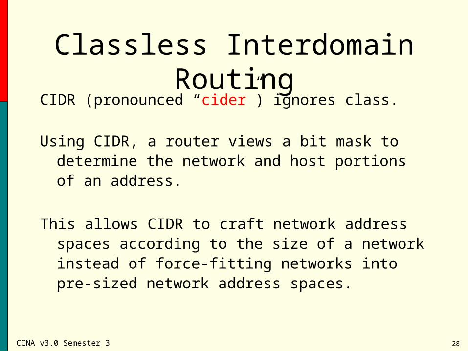
Classless Interdomain RoutingCIDR (pronounced “cider”) ignores class.
Using CIDR, a router views a bit mask to determine the network and host portions of an address.
This allows CIDR to craft network address spaces according to the size of a network instead of force-fitting networks into pre-sized network address spaces.
CCNA v3.0 Semester 3 29
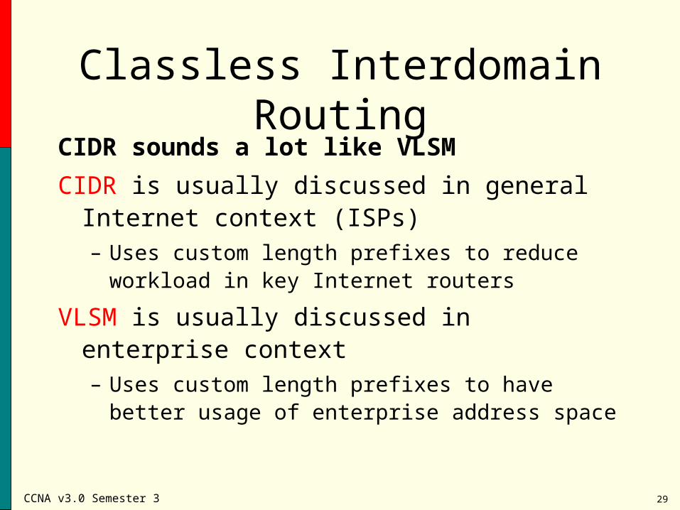
Classless Interdomain RoutingCIDR sounds a lot like VLSM
CIDR is usually discussed in general Internet context (ISPs)– Uses custom length prefixes to reduce workload in
key Internet routers
VLSM is usually discussed in enterprise context– Uses custom length prefixes to have better usage
of enterprise address space
CCNA v3.0 Semester 3 30
Classless Interdomain RoutingRouters use the network-prefix, rather than the first 3
bits of the IP address, to determine the dividing point between the network number and the host number.
In the CIDR model, each piece of routing information is advertised with a bit mask or prefix-length ( /x ). The prefix-length is a way of specifying the number bits in the network-portion of each routing table entry.
CCNA v3.0 Semester 3 31
Classless Interdomain RoutingFor example, a network with 20 bits of network-number
and 12 bits of host-number would be advertised with a 20 bit prefix (/20).
The clever thing is that the IP address advertised with the /20 prefix could be a former Class A, Class B, or Class C.
All addresses with a /20 prefix represent the same amount of address space (212 or 4,096 host addresses).
20 bits network + 12 bits host
CCNA v3.0 Semester 3 32
Classless Interdomain RoutingAddress space can now be assigned in “chunks” that fit
the need.
If an organization needs 254 host addresses, what difference does it make whether they are given:– a Class C (200.23.76.0 /24)
– 1/256th of a Class B (145.38.20.0 /24)
– 1/65,536th of a Class A (91.187.7.0 /24)
Using a /24 prefix, each of these specifies eight host bits which will support 254 hosts.
CCNA v3.0 Semester 3 33
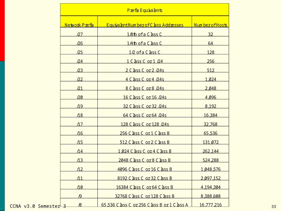
Network Prefix Equivalent Number of Class Addresses Number of Hosts
/27 1/8th of a Class C 32
/26 1/4th of a Class C 64
/25 1/2 of a Class C 128
/24 1 Class C or 1 /24 256
/23 2 Class C or 2 /24s 512
/22 4 Class C or 4 /24s 1,024
/21 8 Class C or 8 /24s 2,048
/20 16 Class C or 16 /24s 4,096
/19 32 Class C or 32 /24s 8,192
/18 64 Class C or 64 /24s 16,384
/17 128 Class C or 128 /24s 32,768
/16 256 Class C or 1 Class B 65,536
/15 512 Class C or 2 Class B 131,072
/14 1,024 Class C or 4 Class B 262,144
/13 2048 Class C or 8 Class B 524,288
/12 4096 Class C or 16 Class B 1,048,576
/11 8192 Class C or 32 Class B 2,097,152
/10 16384 Class C or 64 Class B 4,194,304
/9 32768 Class C or 128 Class B 8,388,608
/8 65,536 Class C or 256 Class B or 1 Class A 16,777,216
Prefix Equivalents
CCNA v3.0 Semester 3 34
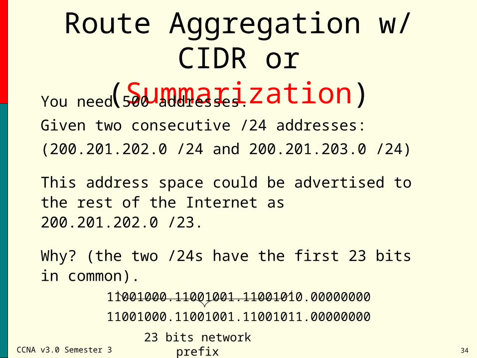
Route Aggregation w/ CIDR or (Summarization)
You need 500 addresses.
Given two consecutive /24 addresses:
(200.201.202.0 /24 and 200.201.203.0 /24)
This address space could be advertised to the rest of the Internet as 200.201.202.0 /23.
Why? (the two /24s have the first 23 bits in common). 11001000.11001001.11001010.00000000
11001000.11001001.11001011.00000000
23 bits network prefix
CCNA v3.0 Semester 3 35
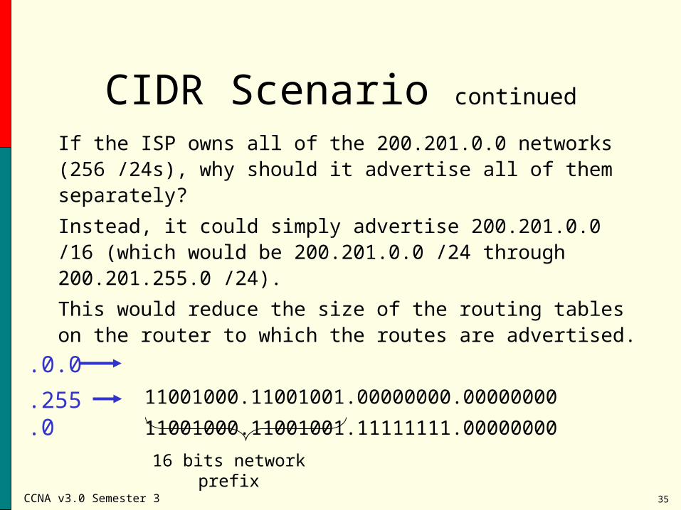
CIDR Scenario continued
If the ISP owns all of the 200.201.0.0 networks (256 /24s), why should it advertise all of them separately?
Instead, it could simply advertise 200.201.0.0 /16 (which would be 200.201.0.0 /24 through 200.201.255.0 /24).
This would reduce the size of the routing tables on the router to which the routes are advertised.
11001000.11001001.00000000.00000000
11001000.11001001.11111111.00000000
16 bits network prefix
.0.0
.255.0
CCNA v3.0 Semester 3 36
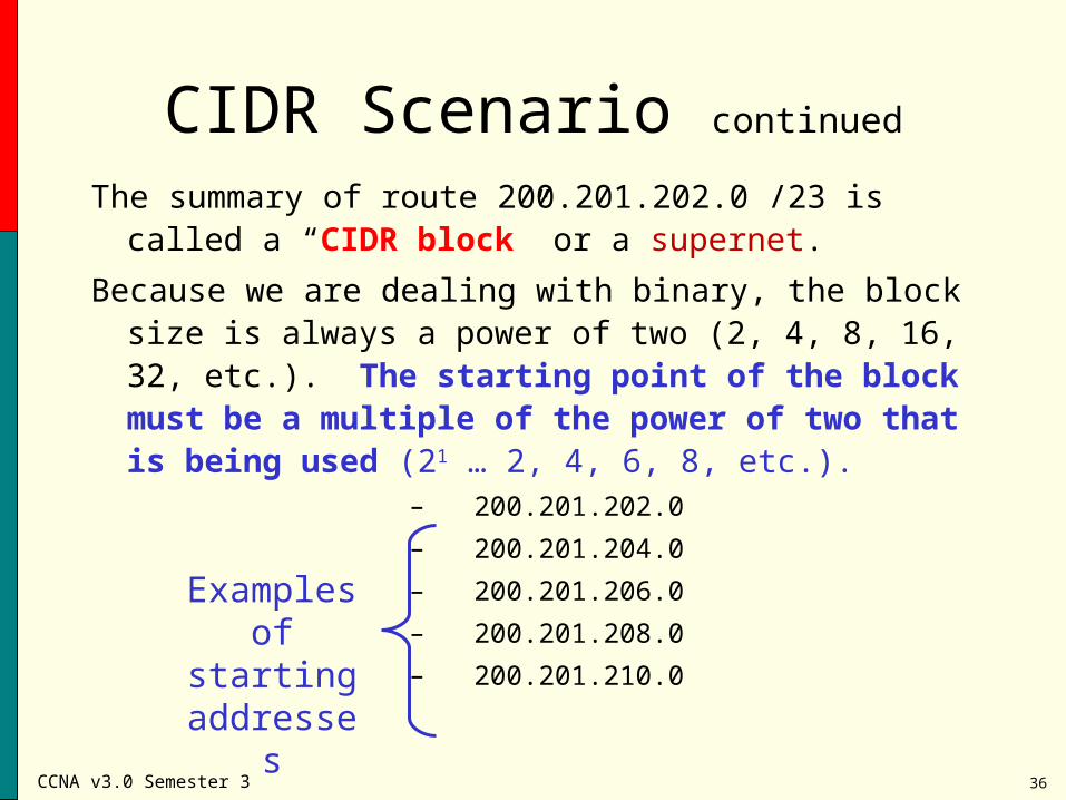
CIDR Scenario continued
The summary of route 200.201.202.0 /23 is called a “CIDR block” or a supernet.
Because we are dealing with binary, the block size is always a power of two (2, 4, 8, 16, 32, etc.). The starting point of the block must be a multiple of the power of two that is being used (21 … 2, 4, 6, 8, etc.).
– 200.201.202.0
– 200.201.204.0
– 200.201.206.0
– 200.201.208.0
– 200.201.210.0
Examples of starting addresses
CCNA v3.0 Semester 3 37
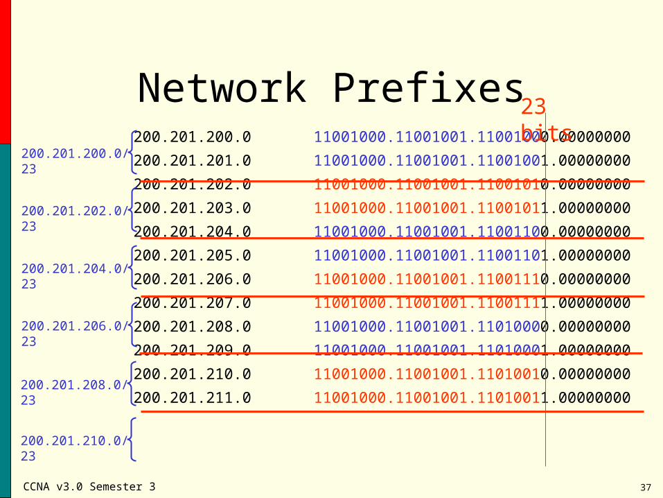
Network Prefixes200.201.200.0 11001000.11001001.11001000.00000000
200.201.201.0 11001000.11001001.11001001.00000000
200.201.202.0 11001000.11001001.11001010.00000000
200.201.203.0 11001000.11001001.11001011.00000000
200.201.204.0 11001000.11001001.11001100.00000000
200.201.205.0 11001000.11001001.11001101.00000000
200.201.206.0 11001000.11001001.11001110.00000000
200.201.207.0 11001000.11001001.11001111.00000000
200.201.208.0 11001000.11001001.11010000.00000000
200.201.209.0 11001000.11001001.11010001.00000000
200.201.210.0 11001000.11001001.11010010.00000000
200.201.211.0 11001000.11001001.11010011.00000000
23 bits
200.201.200.0/23
200.201.202.0/23
200.201.204.0/23
200.201.206.0/23
200.201.208.0/23
200.201.210.0/23
CCNA v3.0 Semester 3 38
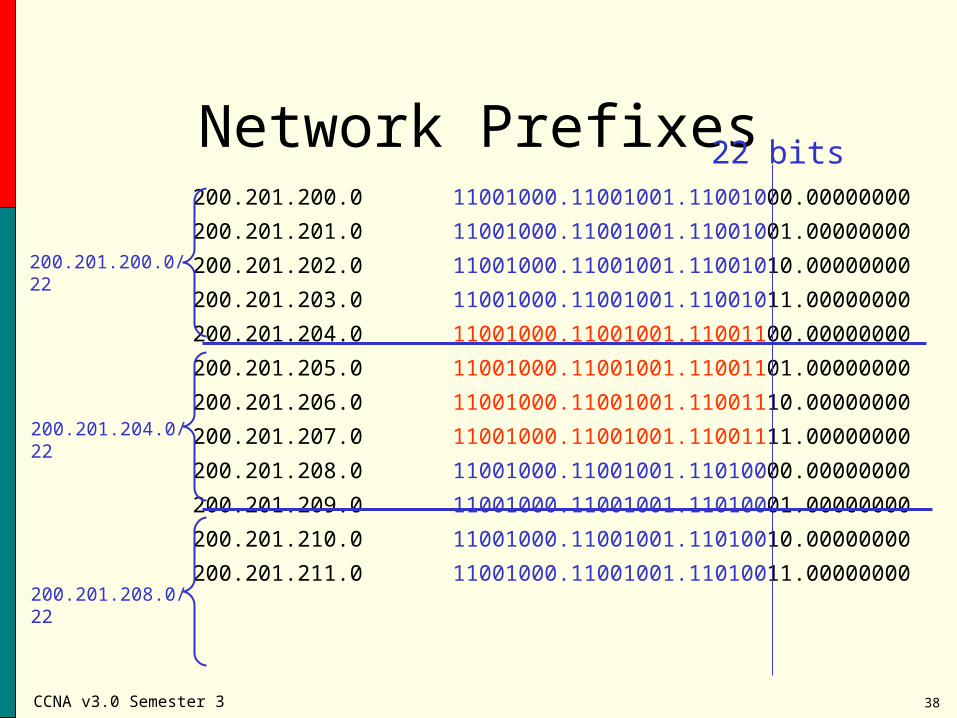
Network Prefixes200.201.200.0 11001000.11001001.11001000.00000000
200.201.201.0 11001000.11001001.11001001.00000000
200.201.202.0 11001000.11001001.11001010.00000000
200.201.203.0 11001000.11001001.11001011.00000000
200.201.204.0 11001000.11001001.11001100.00000000
200.201.205.0 11001000.11001001.11001101.00000000
200.201.206.0 11001000.11001001.11001110.00000000
200.201.207.0 11001000.11001001.11001111.00000000
200.201.208.0 11001000.11001001.11010000.00000000
200.201.209.0 11001000.11001001.11010001.00000000
200.201.210.0 11001000.11001001.11010010.00000000
200.201.211.0 11001000.11001001.11010011.00000000
22 bits
200.201.204.0/22
200.201.200.0/22
200.201.208.0/22
CCNA v3.0 Semester 3 39
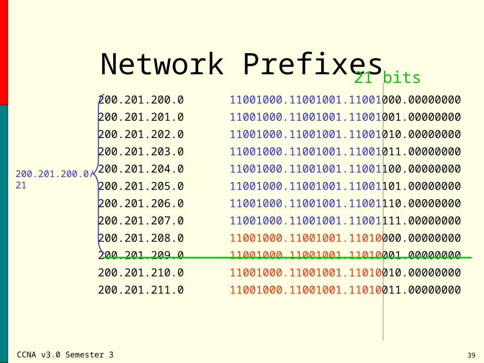
Network Prefixes200.201.200.0 11001000.11001001.11001000.00000000
200.201.201.0 11001000.11001001.11001001.00000000
200.201.202.0 11001000.11001001.11001010.00000000
200.201.203.0 11001000.11001001.11001011.00000000
200.201.204.0 11001000.11001001.11001100.00000000
200.201.205.0 11001000.11001001.11001101.00000000
200.201.206.0 11001000.11001001.11001110.00000000
200.201.207.0 11001000.11001001.11001111.00000000
200.201.208.0 11001000.11001001.11010000.00000000
200.201.209.0 11001000.11001001.11010001.00000000
200.201.210.0 11001000.11001001.11010010.00000000
200.201.211.0 11001000.11001001.11010011.00000000
21 bits
200.201.200.0/21
CCNA v3.0 Semester 3 40
CIDR in a NutshellHand out pieces of classful networks (to avoid wasting
addresses)
Identify the network portion of an address with a network prefix ( /x)
Advertise blocks of networks (to reduce the size of routing tables).
CCNA v3.0 Semester 3 41
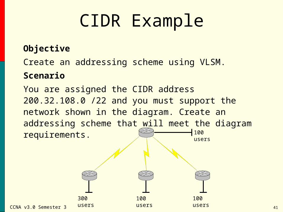
CIDR Example
Objective
Create an addressing scheme using VLSM.
Scenario
You are assigned the CIDR address 200.32.108.0 /22 and you must support the network shown in the diagram. Create an addressing scheme that will meet the diagram requirements.
300 users 100 users 100 users
100 users
CCNA v3.0 Semester 3 42
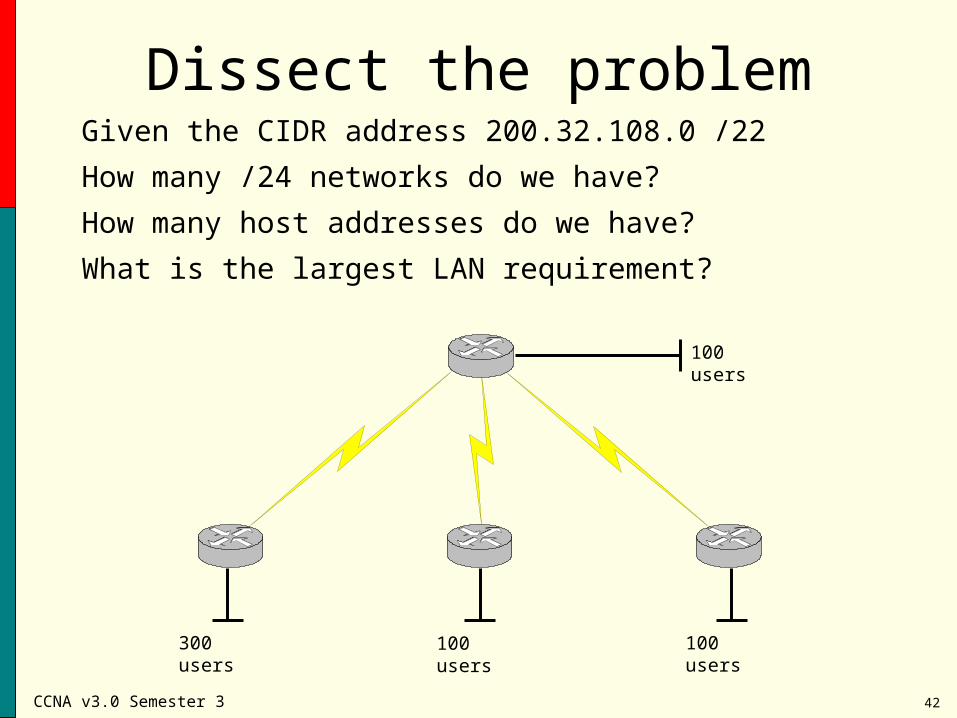
Dissect the problemGiven the CIDR address 200.32.108.0 /22
How many /24 networks do we have?
How many host addresses do we have?
What is the largest LAN requirement?
300 users 100 users 100 users
100 users
CCNA v3.0 Semester 3 43
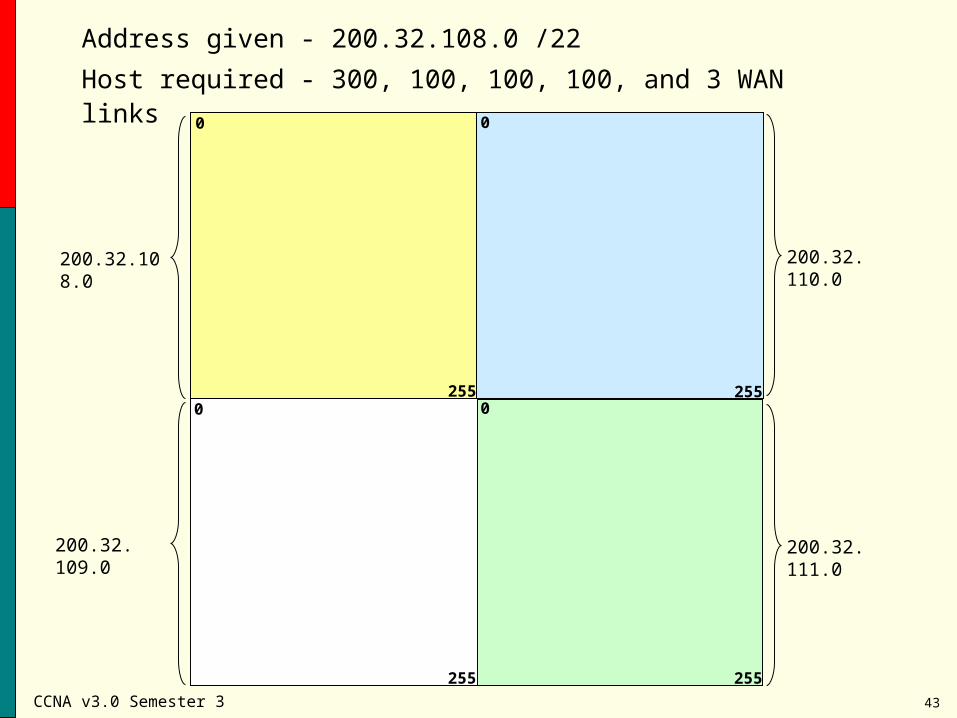
Address given - 200.32.108.0 /22
Host required - 300, 100, 100, 100, and 3 WAN links
200.32.108.0 200.32. 110.0
0 0
0 0255 255
255 255
200.32. 109.0 200.32. 111.0
CCNA v3.0 Semester 3 44
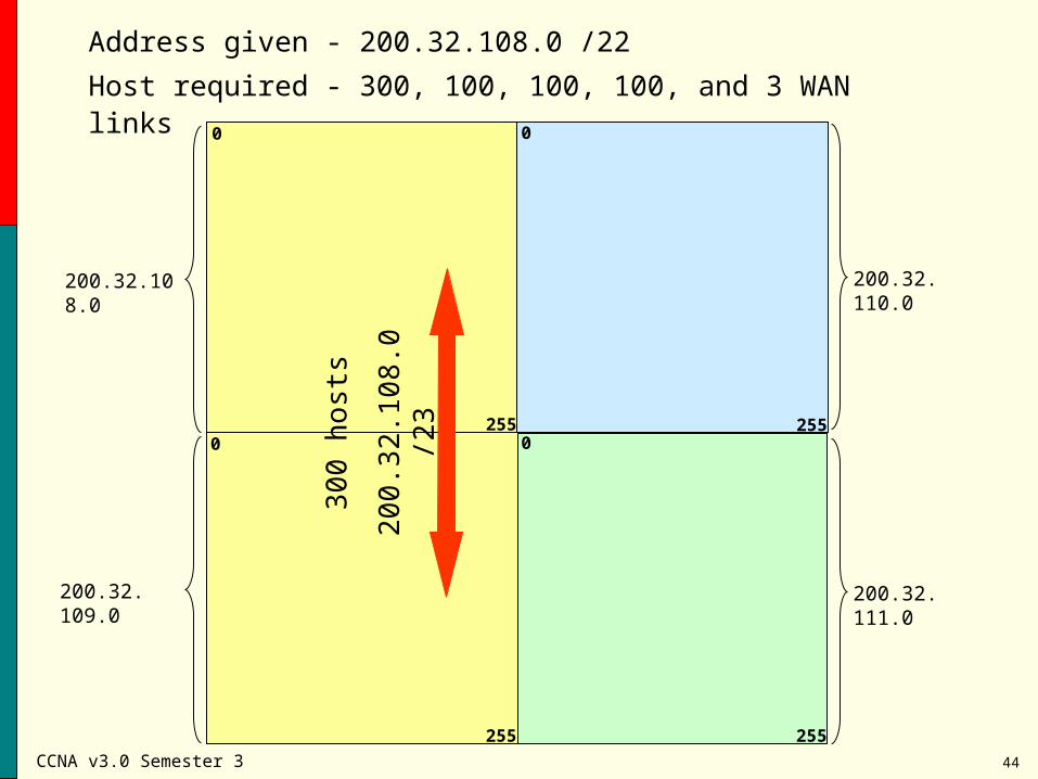
Address given - 200.32.108.0 /22
Host required - 300, 100, 100, 100, and 3 WAN links0 0
0 0255 255
255 255
300
hos
ts
200
.32.
108
.0 /2
3
200.32.108.0 200.32. 110.0
200.32. 109.0 200.32. 111.0
CCNA v3.0 Semester 3 45
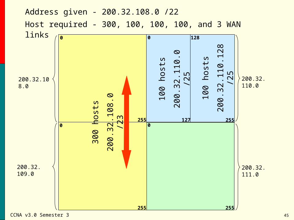
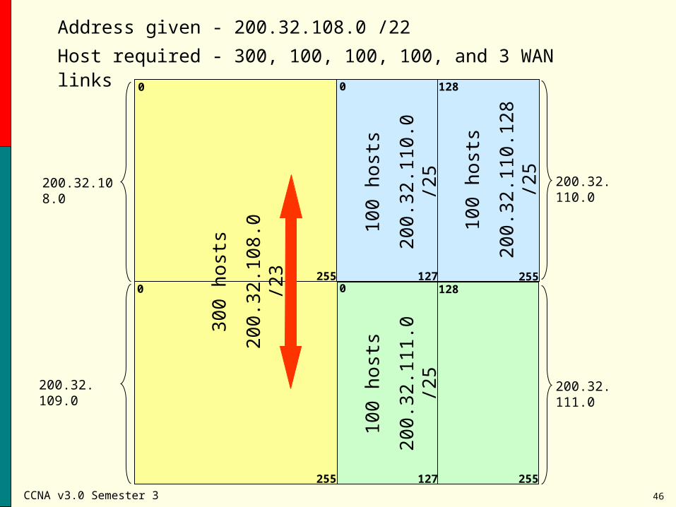
Address given - 200.32.108.0 /22
Host required - 300, 100, 100, 100, and 3 WAN links0 0
0 0255 255
255 255
300
hos
ts
200
.32.
108
.0 /2
3127
128
100
hos
ts
200
.32.
110
.0 /2
5
100
hos
ts
200
.32.
110
.128
/25
200.32.108.0 200.32. 110.0
200.32. 109.0 200.32. 111.0
CCNA v3.0 Semester 3 46
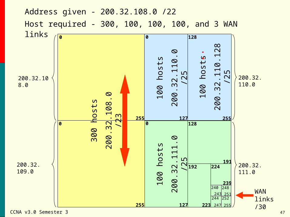
Address given - 200.32.108.0 /22
Host required - 300, 100, 100, 100, and 3 WAN links0 0
0 0255 255
255 255
300
hos
ts
200
.32.
108
.0 /2
3127
128
100
hos
ts
200
.32.
110
.0 /2
5
100
hos
ts
200
.32.
110
.128
/25
127
128
100
hos
ts
200
.32.
111
.0 /2
5
200.32.108.0 200.32. 110.0
200.32. 109.0 200.32. 111.0
CCNA v3.0 Semester 3 47
Address given - 200.32.108.0 /22
Host required - 300, 100, 100, 100, and 3 WAN links0 0
0 0255 255
255 255
300
hos
ts
200
.32.
108
.0 /2
3127
128
100
hos
ts
200
.32.
110
.0 /2
5
100
hos
ts
200
.32.
110
.128
/25
127
128
100
hos
ts
200
.32.
111
.0 /2
5
191192
223
224
248
247
243252
251244
WAN links /30
240239
200.32.108.0 200.32. 110.0
200.32. 109.0 200.32. 111.0
CCNA v3.0 Semester 3 48
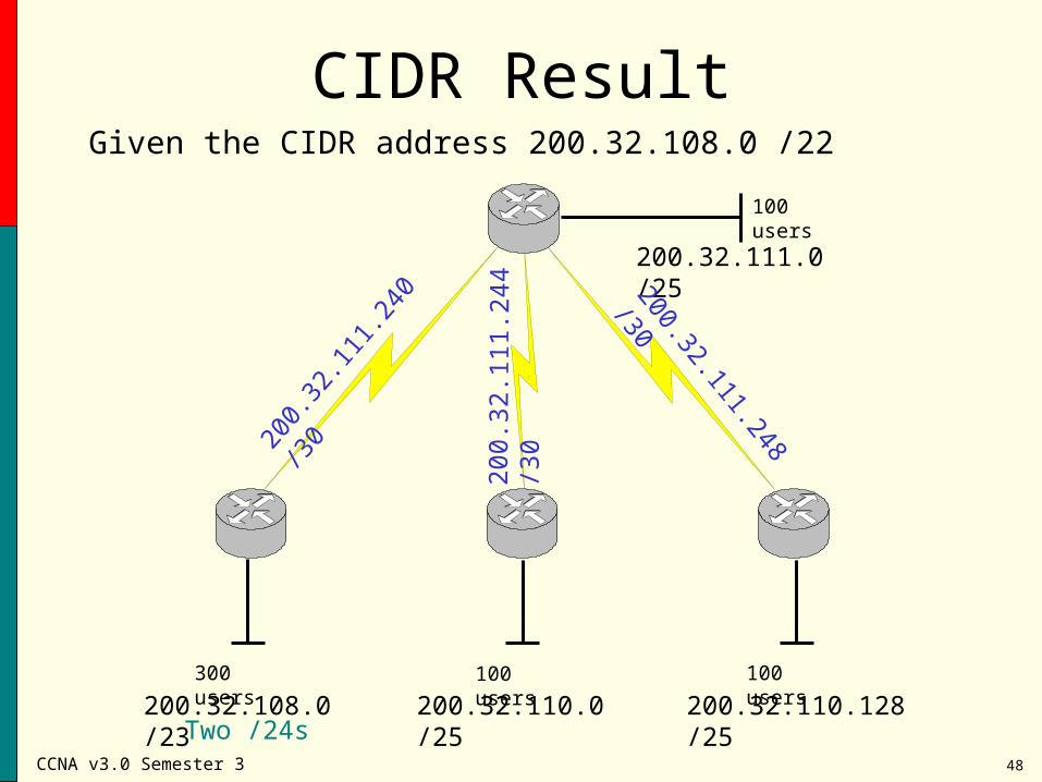
CIDR ResultGiven the CIDR address 200.32.108.0 /22
300 users 100 users 100 users
100 users
200.32.108.0 /23 200.32.110.0 /25 200.32.110.128 /25
200.32.111.0 /2520
0.32
.111
.240
/30 200.32.111.248 /30
200.
32.1
11.2
44 /
30
Two /24s
CCNA v3.0 Semester 3 49
Classless Interdomain RoutingFor the router to operate in a classless manner and match destination IP addresses to a CIDR network address,
The global command: ip classless must be configured.
Router(config)# ip classless
CCNA v3.0 Semester 3 50
Routing Information Protocol(RIP)
•RIP is a relatively old, but still commonly used interior gateway protocol (IGP).
•It was created for use in small homogeneous networks.
•It is a distance-vector protocol that is used with classful IP addressing only.
•RIP v1 sends routing update messages at regular intervals (30 seconds) and when the network topology changes.
•RIP uses hop count as its only metric and maintains only the best route to a destination.
CCNA v3.0 Semester 3 51
RIP Version 2
•Known as RIP V2
In RIP v2 all of the operation procedures, timers, and
stability functions of RIP v1 remain the same in version
2, with the exception of the broadcast updates.
RIP v2 has become the standard version of RIP used
in networks today.
CCNA v3.0 Semester 3 52
RIP V2 is RIP V1 with extensions
• Subnet masks carried with each route entry
• Authentication of routing updates
• Next-hop addresses carried with each route entry
• External route tags
• Multicast route updates
CCNA v3.0 Semester 3 53
RIP v2
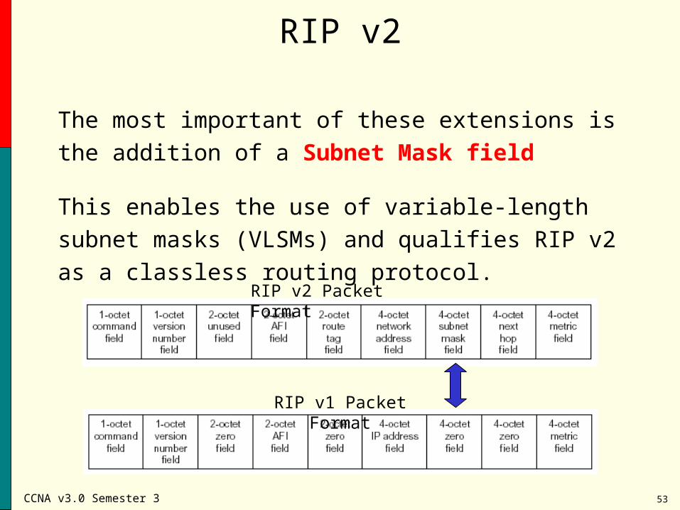
The most important of these extensions is the addition
of a Subnet Mask field
This enables the use of variable-length subnet masks
(VLSMs) and qualifies RIP v2 as a classless routing
protocol.RIP v2 Packet Format
RIP v1 Packet Format
CCNA v3.0 Semester 3 54
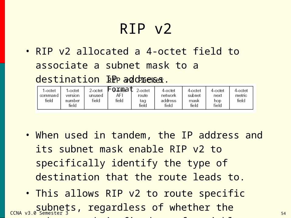
RIP v2
• RIP v2 allocated a 4-octet field to associate a subnet
mask to a destination IP address.
• When used in tandem, the IP address and its subnet
mask enable RIP v2 to specifically identify the type of
destination that the route leads to.
• This allows RIP v2 to route specific subnets,
regardless of whether the subnet mask is fixed or of
variable length.
RIP v2 Packet Format
CCNA v3.0 Semester 3 55
RIP v2
RIP v2 differs from RIP v1 in the way update aresent out.
• RIP v1 sends updates as a broadcast (all stations
receive the broadcast message)
• RIP v1 does not send subnet mask information in
its updates.
• RIP v2 sends updates as a multi-cast. Multi-casting
is a technique for simultaneously advertising routing
information to multiple RIP devices via the class D
address 224.0.0.9
CCNA v3.0 Semester 3 56
RIP v1 & RIP v2 comparisons
• Both use hop count as a metric
• Both have the same metric value for infinite distance (16)
• Both use split horizon to prevent routing loops.
• RIP v1 broadcasts routing table updates, while RIP v2 multicasts its updates
CCNA v3.0 Semester 3 57
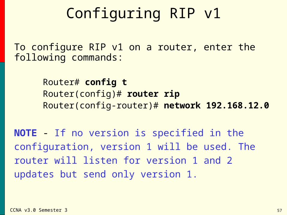
Configuring RIP v1
To configure RIP v1 on a router, enter the following commands:
Router# config tRouter(config)# router ripRouter(config-router)# network 192.168.12.0
NOTE - If no version is specified in the configuration, version
1 will be used. The router will listen for version 1 and 2
updates but send only version 1.
CCNA v3.0 Semester 3 58
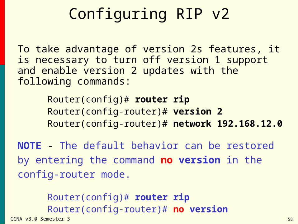
Configuring RIP v2
To take advantage of version 2s features, it is necessary to turn off version 1 support and enable version 2 updates with the following commands:
Router(config)# router ripRouter(config-router)# version 2
Router(config-router)# network 192.168.12.0
NOTE - The default behavior can be restored by entering the
command no version in the config-router mode.
Router(config)# router ripRouter(config-router)# no version
CCNA v3.0 Semester 3 59
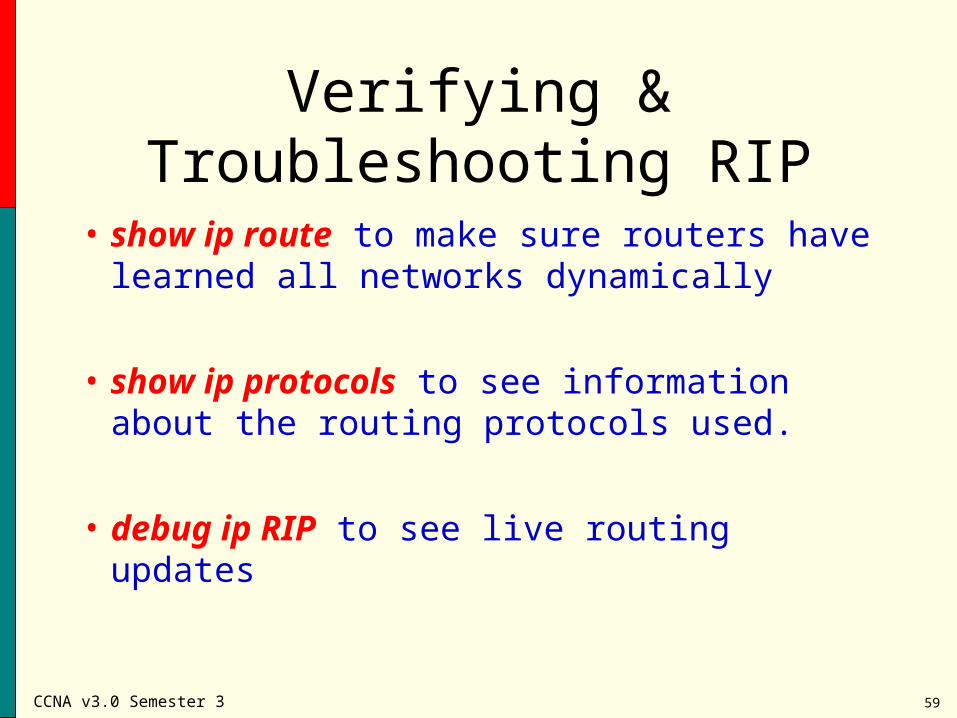
Verifying & Troubleshooting RIP
• show ip route to make sure routers have learned all networks dynamically
• show ip protocols to see information about the routing protocols used.
• debug ip RIP to see live routing updates
CCNA v3.0 Semester 3 60
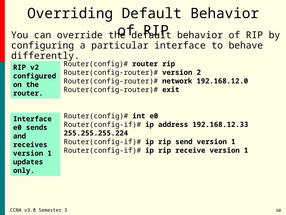
You can override the default behavior of RIP by configuring a particular interface to behave differently.
Overriding Default Behavior of RIP
Interface e0 sends and receives version 1 updates only.
RIP v2 configured on the router.
Router(config)# router ripRouter(config-router)# version 2Router(config-router)# network 192.168.12.0Router(config-router)# exit
Router(config)# int e0Router(config-if)# ip address 192.168.12.33 255.255.255.224Router(config-if)# ip rip send version 1Router(config-if)# ip rip receive version 1
CCNA v3.0 Semester 3 61
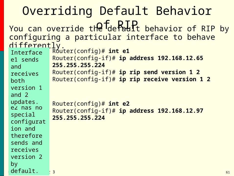
You can override the default behavior of RIP by configuring a particular interface to behave differently.
Interface e2 has no special configuration and therefore sends and receives version 2 by default.
Overriding Default Behavior of RIP
Interface e1 sends and receives both version 1 and 2 updates.
Router(config)# int e1Router(config-if)# ip address 192.168.12.65 255.255.255.224 Router(config-if)# ip rip send version 1 2 Router(config-if)# ip rip receive version 1 2
Router(config)# int e2Router(config-if)# ip address 192.168.12.97 255.255.255.224
CCNA v3.0 Semester 3 62
Review of Static & Default Routing
CCNA v3.0 Semester 3 63
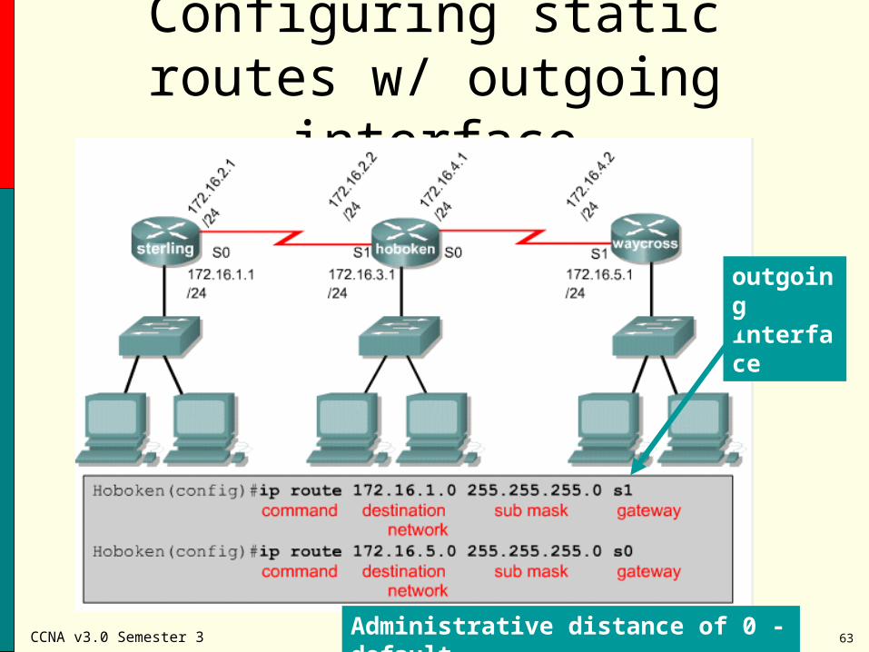
Configuring static routes w/ outgoing interface
Administrative distance of 0 - default
outgoing interface
CCNA v3.0 Semester 3 64
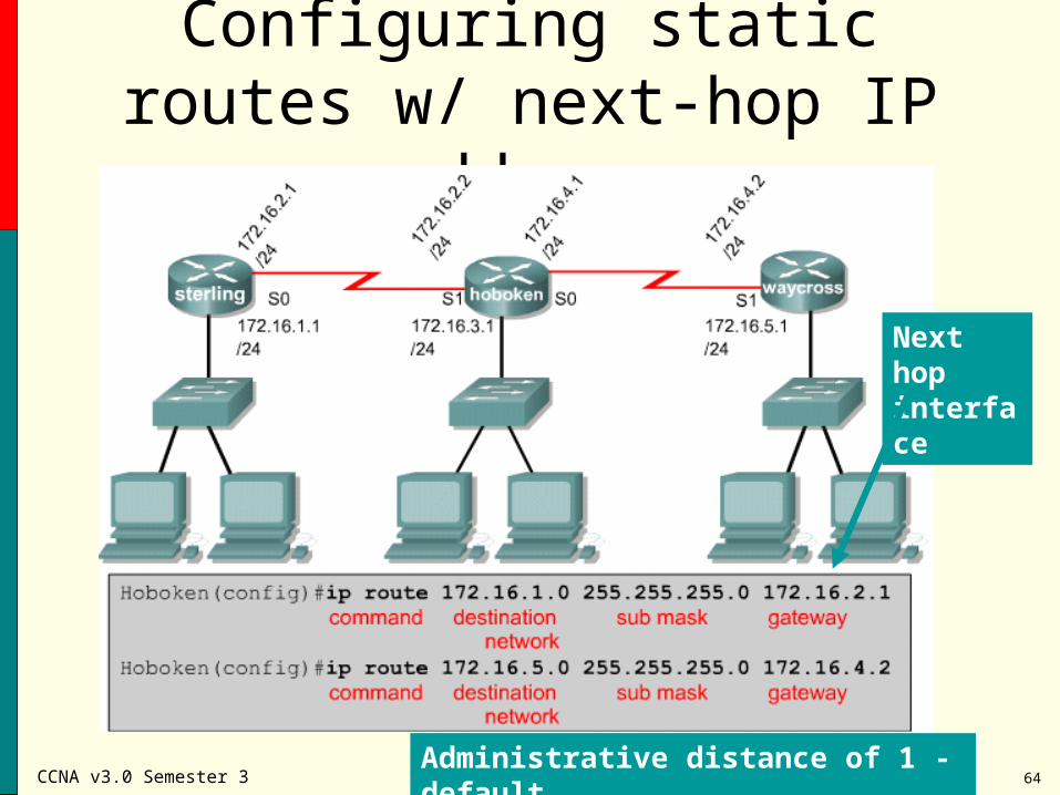
Configuring static routes w/ next-hop IP address
Administrative distance of 1 - default
Next hop interface
CCNA v3.0 Semester 3 65
Configuring Static RoutesRemember, an administrator actually enters these routes into the
routing table.That makes them static route entries – because the router is not
“discovering” those routes.If for some reason that outgoing interface goes down or is not
available for some reason, then at that time the route will be removed from the routing table.
Show ip route shows the routing table.The route would still be in the configuration (because it was entered
globally), but that route could now no longer be used by the router because the interface it refers to is down for some reason.
CCNA v3.0 Semester 3 66
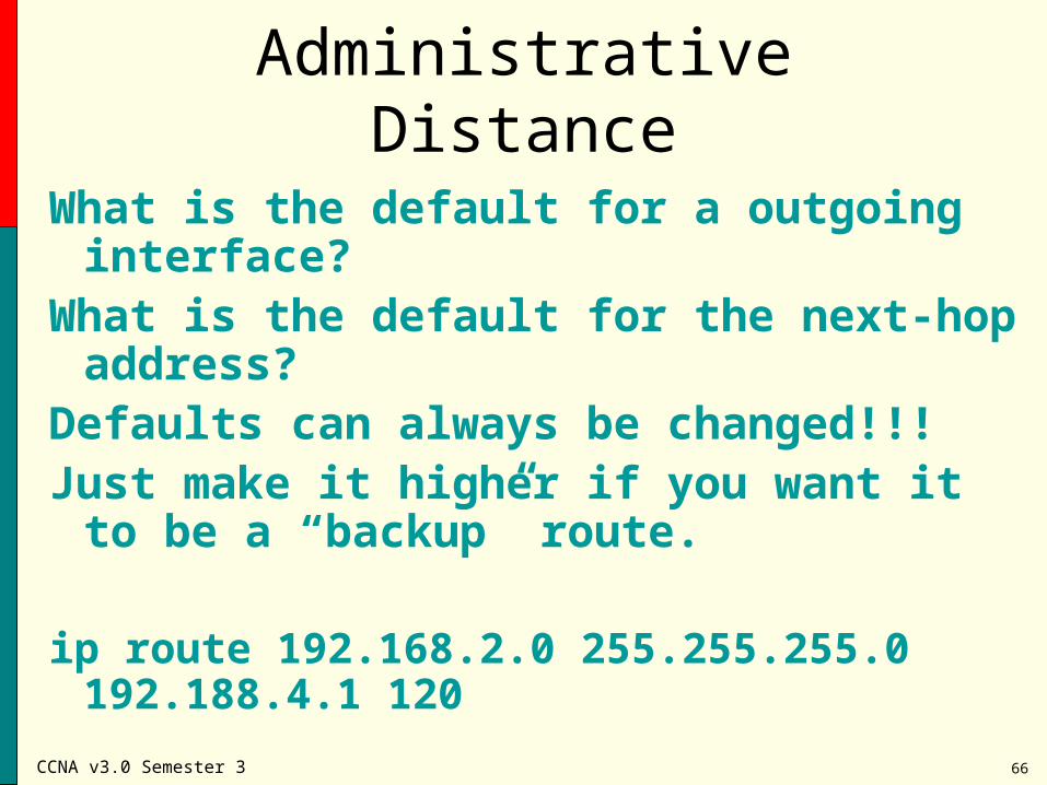
Administrative Distance
What is the default for a outgoing interface?What is the default for the next-hop address?Defaults can always be changed!!!Just make it higher if you want it to be a
“backup” route.
ip route 192.168.2.0 255.255.255.0 192.188.4.1 120
CCNA v3.0 Semester 3 67
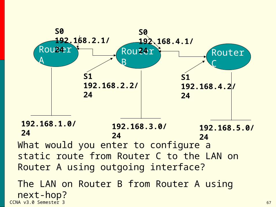
Router A Router B Router C
S0 192.168.2.1/24
S1 192.168.2.2/24
S0 192.168.4.1/24
S1 192.168.4.2/24
192.168.1.0/24 192.168.3.0/24 192.168.5.0/24
What would you enter to configure a static route from Router C to the LAN on Router A using outgoing interface?
The LAN on Router B from Router A using next-hop?
CCNA v3.0 Semester 3 68
The static default route
A router should be configured with a special type of static route – a default route.
This default route routes packets with destinations that do not match any of the other routes in the routing table
It is a “gateway of last resort” that allows the router to forward “destination unknown” packets out a particular interface
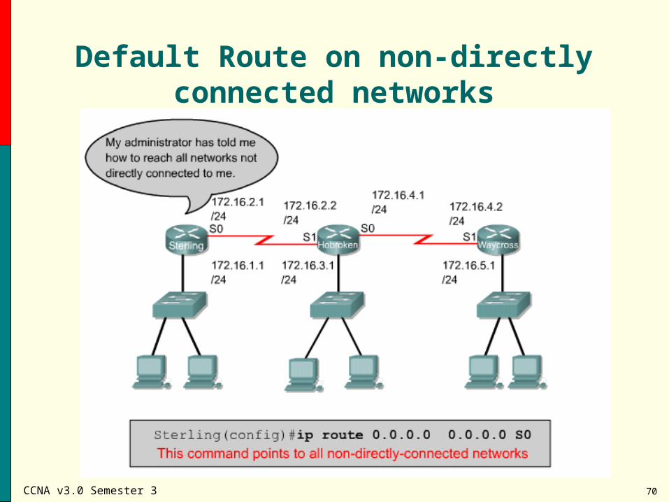
ip route 0.0.0.0 0.0.0.0 [next-hop-address | outgoing interface]
CCNA v3.0 Semester 3 69
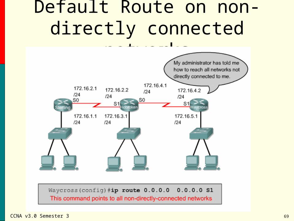
Default Route on non-directly connected networks
CCNA v3.0 Semester 3 70
Default Route on non-directly connected networks
CCNA v3.0 Semester 3
CCNA v3.0Module 1
Introduction to Classless Routing
Top Related