


Languages
Pages
Legal


Carbidic Ductile IronCarbidic Ductile Iron
Marc KingMetallurgistMetallurgist
Hiler IndustriesLaPorte, IN

Why would anybody in their right mind want to addright mind want to add
carbides to ductile iron?

Ductile Iron is a great engineering material:
Great StrengthGreat Strength
Good Elongation
Excellent Castability
Excellent Machinability
Heat Treatable
Highly Adaptableg y p
U f t t l it ti lti t lUnfortunately its wear properties ultimately needed some improvement!
Abrasive Wear

Where to begin?g
H d k l d il i i hi hlHow do you make normal ductile iron into a highly abrasion resistant material?

Lets take a look at traditional abrasion resistant cast irons:
White Iron
Ni-Hard IronNi-Hard Iron

ASTM A532 15% Cr-Mo White IronEtched 1000X Precipitation CarbidesEtched, 1000X Precipitation Carbides
Chemical S ifi iSpecifications
C: 2.00 - 3.30%
Mn: 2.0 Max
Si: 1.5% Max
Ni: 2.5% Max
Cr: 14 - 18%Complex Chromium Carbides
Martensitic Matrix after h t t t t
Cr: 14 18%
Mo: 3.0% Max
Cu: 1 2% MaxCarbides heat treatment.
Hardness Spec: 59 Rc Min.
Cu: 1.2% Max
S: 0.06% Max

ASTM A532 15% Cr-Mo White Iron
Good Properties:
1) Extremely Wear Resistant
Bad Properties:
1) Brittle
2) Difficult to cast in thin sections and complex shapes.) p p
3) Shrink Prone.
4) Expensive alloys with limited availability and volatile pricing4) Expensive alloys with limited availability and volatile pricing.

ASTM A532 1D Ni-Hard IronEtched, 1000X
Chemical Specifications:
C: 2.7 - 3.20%
Si: 1.60 - 1.70%Si: 1.60 1.70%
Mn: 0.50 - 0.70%
Cr: 7 0 11 0%
Complex Austenite
Cr: 7.0 - 11.0%
Mo: 0.00 - 1.50%
Chromium Carbide
AusteniteMartensite Ni: 4.50 - 4.90%
Hardness Specification: 500 BHN Min.

ASTM A532 1D Ni-Hard Iron
Good Properties:
1) W R i t t1) Wear Resistant
2) Impact Resistant
Bad Properties:
1) Brittle)
2) Difficult to cast in thin sections and complex shapes.
3) Shrink Prone3) Shrink Prone
4) Expensive Alloys with limited availability and volatile pricing.
What do wear resistant irons haveWhat do wear resistant irons have that traditional ductile iron doesn’t?

Carbides!Carbides!

What is Carbidic Ductile Iron?
1) Carbidic Ductile Iron has no ASTM designation.
2) A normal carbide specification is 10 - 30 % of the matrix2) A normal carbide specification is 10 - 30 % of the matrix.
3) Nodularity is a minimum of 70%. This specification is loose due to the lack of nucleation needed to stabilizeloose due to the lack of nucleation needed to stabilize carbides, and carbide formation causing poor nodule formation.
4) The grades that Hiler Industries produces are austempered to increase matrix hardness and the toughness of the metal. Final Hardness is 444-555 BHN This produces a metal withFinal Hardness is 444-555 BHN. This produces a metal with similar physical properties to Ni-Hard alloys.

So how do we get carbides into the iron when we have spent our whole
career getting them out?
Happy Metallurgist Unhappy Metallurgist
Thought process behind making Carbidic Ductile Iron:
1) This iron is basically a compromise between making a Ductile Iron Alloy and a “White Iron” or Ni-hard Alloy.
2) M th ht th t h t k l D til2) My thought was that you have to make normal Ductile Iron, but modify your process to stabilize the desired % carbides without completely sacrificing nodule formation and nodule count.
3) The starting point, in the beginning, was a normal ductile b i h h i l d h ibase iron. The charge materials and chemistry were not changed.
4) Magnesi m treatment method does not change beca se4) Magnesium treatment method does not change, because good nodularity is required to give the metal impact toughness.

Thought process behind making Carbidic Ductile Iron:
5) Carbide stabilizing alloys are added.
6) Inoculation is reduced to maximize carbide stabilization and )while providing some potential for nodule formation.

Carbide Stabilizing Alloys in Carbidic Ductile Iron
Elements:Elements:
Chromium
M l bdMolybdenum
Manganese
Copper (Minor Effect)
Use the most cost effective carbide stabilizers.
Do not overcomplicate the interpretation of the results by using too many alloys. It is best to simplify alloy additions.
The level of carbide stabilizing alloy will be proportional to the % Carbides formed.
The level of carbide stabilizer may have to be increased for thicker sectioned castings.

Inoculation of Carbidic Ductile Iron
The addition of carbide stabilizers will cause thin sections toThe addition of carbide stabilizers will cause thin sections to become almost completely carbidic.
Inoculation is reduced to maximize carbide stabilization.ocu o s educed o e c b de s b o .
A small inoculation must be added to maintain graphite nucleation potential in the thin sections.
The elimination of inoculation causes carbidic ductile iron to be extremely brittle in sections under 1/4 inch thickness due to a combination of poor nodule count and high % carbide formation.
Inoculation promotes graphite sphere roundness in carbidic d til iductile iron.
Low levels of inoculation promotes growth of nodules in the thin sections to prevent stress cracking that can occur duringthin sections to prevent stress cracking that can occur during austempering heat treatment if the nodule count is insufficient.

Unetched 100X Magnification
Graphite Structure of Carbidic Ductile Iron
Unetched, 100X Magnification
Nodularity: 90%2NC: 100 Nod/mm2
% Graphite: 6%
Fully spherical graphite formation is difficult to achieve in carbidic ductile iron. This is not due to the effects of magnesium treatment.

Etched, 500X MagnificationGraphite Structure of Carbidic Ductile Iron
, g
Etching the sample reveals that particles of carbide intersect the g p pgraphite spheres. This gives the appearance that the graphite spheres are deteriorated in an unetched view.

Graphite Structure of Carbidic Ductile Iron
% Nodularity less than 90% is common due to carbide formation impairing the graphite nucleation. The carbide f ti t i t th hit d l th l tiformation cuts into the graphite nodules as they are nucleating causing graphite that appears to be deteriorating.
% Nodularity is a secondary criteria The customer% Nodularity is a secondary criteria. The customer specifications often stress wear properties and carbide formation over % Nodularity as being a passing criteria.

As-Cast Matrix Microstructure of Carbidic Ductile Iron
Etched, 200XCarbide isCarbide is stabilized through the addition of
bid t bilicarbide stabilizers combined with a low % inoculation.
Note: Complex intercellular carbide formation.

Etched 500X
As-Cast Matrix Microstructure of Carbidic Ductile Iron
Etched, 500XThe use of carbide stabilizersstabilizers causes the stabilization of fine pearlite lamella in the matrix.
It is common in Carbidic Ductile Iron for carbide formations toIt is common in Carbidic Ductile Iron for carbide formations to intersect graphite nodules, and to see intercellular carbide surrounding graphite nodules.

The use of carbide stabilizers causes the stabilization of fine pearlite lamella in the matrix
Etched, 1000X Graphite Nodule intersected Complex
lamella in the matrix.
pIntercellular Carbides during nucleation and growthgrowth.
Matrix: Fine sized pearlite with minimal stabilized ferrite.

Thick vs. Thin Sections in Carbidic Ductile Iron
Thick SectionThick Section
Thin Section
Carbide Formation and Nodule Formation vary according to section thickness.
The thicker section in the photo is the critical wear resistant section of the part.
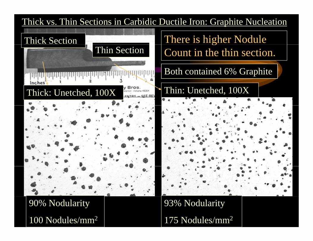
Thick Section There is higher Nodule Thick vs. Thin Sections in Carbidic Ductile Iron: Graphite Nucleation
Thin Sectiong
Count in the thin section.
Both contained 6% Graphite
Thin: Unetched, 100XThick: Unetched, 100X
p
90% Nodularity
100 Nodules/mm2
93% Nodularity
175 Nodules/mm2
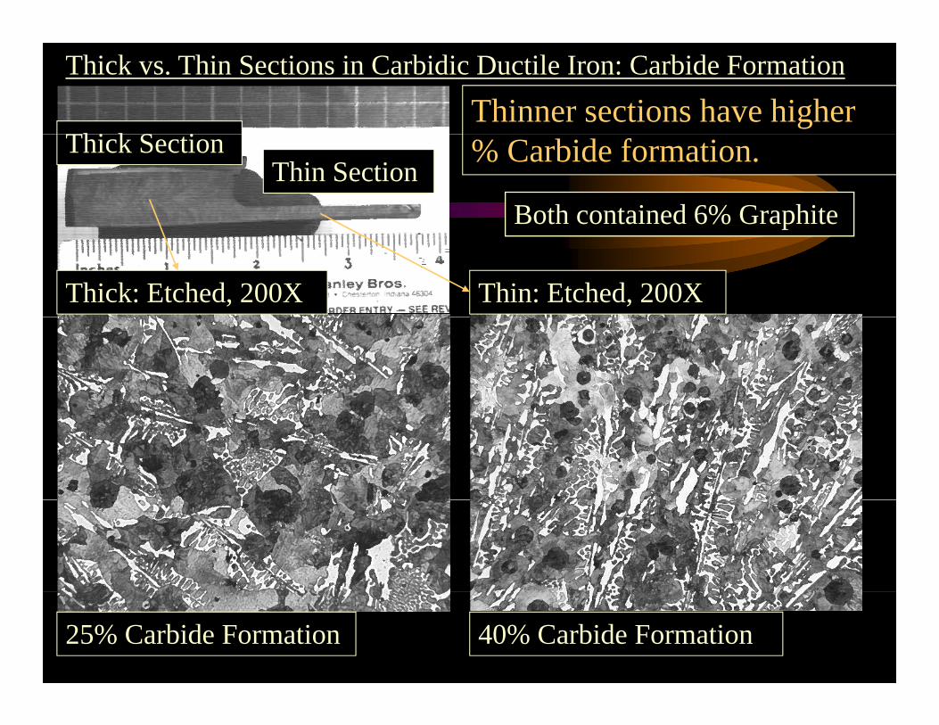
Thick vs. Thin Sections in Carbidic Ductile Iron: Carbide Formation
Thi k S iThinner sections have higher
Thick SectionThin Section
% Carbide formation.
Both contained 6% Graphite
Thin: Etched, 200XThick: Etched, 200X
p
25% Carbide Formation 40% Carbide Formation

Section thickness effects the formation of iron carbide. There is
Thin Sections in Carbidic Ductile Iron
always an area in these castings where the % Carbides in the matrix has to be maintained to give the material wear resistant properties.
M h h hi i 1/4 i h hi k hMany parts that we cast have thin sections, <1/4 inch thick, that are not critical areas for wear resistance. Thin sections will have greater than the maximum allowed % carbides.
Graphite nucleation is promoted in thin sections by adding a small post inoculant addition.
Increasing inoculation (% Silicon) will decrease the amount of carbides throughout the casting.
Inoculate enough to promote some graphite nucleation in the thin sections, but not enough to decrease the carbides in the critical sections to the point where the wear resistant properties aresections to the point where the wear resistant properties are compromised.

Cracking in Carbidic Ductile Iron Due to Lack of Inoculation
The cracks in these castings were the result of early experimentation using no post inoculation combined with a carbide stabilizing alloy to form carbides during solidification.

Cracking in Carbidic Ductile Iron Due to Lack of Inoculation
Thin Section CrackingThin Section Cracking
Oxidized Fracture Surface
Less Than 1/4 inch Thick Section
PaintOxidized Fracture Surface
Transition between thick and thin section.
The crack occurred during austempering heat treatment.

Cracking in Carbidic Ductile Iron Due to Lack of Inoculation
U h d 100X E h d 100XUnetched, 100X Etched, 100X
Matrix: 40% Carbides, Austempered
Graphite: 80% Nodularity, 70 Nodules/mm2
Poor Nodule Shape and Count combined with High % Carbides.
Nodule Count and Shape is better in casting thin sections thatNodule Count and Shape is better in casting thin sections that receive a small post inoculation.

Cracking in Carbidic Ductile Iron Due to Lack of Inoculation
Stress Riser Cracking
The crack d d ioccurred during
austempering heat treatment.
Edge transition between two thick sections at a cast corner.
The cracks in these castings were the result of early experimentation using no post inoculation combined with a carbide stabilizing alloy to form carbides during solidification.

Etched 500X
Cracking in Carbidic Ductile Iron Due to Lack of Inoculation
Etched, 500X
Note the directional carbide growth in thecarbide growth in the uninoculated casting.
Directional growth of the gcarbide in uninoculated carbidic ductile iron makes the material moremakes the material more prone to brittle fracture.
35% Carbides
Austempered Matrix
Small inoculant additions help to produce more random directional carbide growth. Austempered Matrix gThis makes the material tougher and reduces stress cracking.

Wear PropertiesExample of a casting microstructure displaying poor wear properties.
Etched, 200X
p g p y g p p p
10% Carbides in a fully austempered matrix.
Poor carbide formation decreases the wear resistance of the castingresistance of the casting.
Low carbide stabilizer additions and high % Silicon cause poor carbide formation.
Nodule shape is much better with lower % carbide formation.

Wear PropertiesExample of a casting microstructure displaying poor wear properties.p g p y g p p p
h d
Graphite Structure
95% Nodularity NC: 100 Nodules/mm2
Unetched, 100X
NC: 100 Nodules/mm
Nodule shape improves with lower % carbide formation.
Decreased Resistance to wear.

Matrix Microstructure of Carbidic Austempered Ductile Iron
Austempering is the most common means of creating a hardened,
Etched, 500X
creating a hardened, wear resistant matrix microstructure allowing C bidi D til I tCarbidic Ductile Iron to compete with Ni Hard Irons.
Carbidic Austempered Ductile Iron exceeds Ni-Hard in applications where both impact resistance and wear resistanceapplications where both impact resistance and wear resistance are desired properties.

Etched 1000X
Microstructure of Carbidic Austempered Ductile Iron (CADI)
Etched, 1000XThe final material is a Carbidic Ductile Iron with Modified ASTMwith Modified ASTM A897, Grade 230-185-01Austemper Heat T t tTreatment
BHN Range: 444-555
Graphite Nodule
Carbide Acicular Ferrite in a matrix of Austenite.

Points to consider concerning austempering:
The iron will grow during austempering. Stress cracking i i l d bidi i d ican occur in uninoculated, over-carbidic iron during
austempering heat treatment in both thin sections and at sharp corners where changes in plane geometry cause a stress riser to g p g yoccur.
Carbides may dissolve into solid solution during the austenitizing step of the austempering heat treatment. Take this into account when developing your process to produce Carbidic Ductile Iron. Minimal carbide will cause premature wear of theDuctile Iron. Minimal carbide will cause premature wear of the parts in field service.

Conclusions:
Normal ductile iron can be easily modified to produce wear resistant Austempered Carbidic Ductile Iron that can compete with physical properties of the Ni-Hard class of alloys.
The wear resistant properties are achieved by producing as-cast bid i hi h i i b bid bili icarbides within the matrix microstructure by carbide stabilizing
alloy additions combined with reduced inoculation. The matrix is further modified through an austemper heat treatment. This g phardens the matrix and makes a tougher, more impact resistant.
Carbidic Iron is lower cost to produce than Ni-Hard and is not subject to the volatility of alloy prices.
Thank You for your attention!
Any Questions?Any Questions?
Top Related