


Languages
Pages
Legal


User ManualTM
07/1
0 -
Tec
hnic
al d
ata
and
desi
gns
are
non-
cont
ract
ual.
Erla
b® D
FS S
AS
rese
rves
the
rig
ht t
o m
odify
the
doc
umen
t w
ithou
t no
tice.
www.er lab.comerlab® D.F.S S.A.S - Capital social 660 000 € Siren : 667 250 096 / RCS Evreux
Siège social : Parc d’Affaires des Portes - BP 403 27104 Val de Reuil Cedex - FranceTél : +33 (0) 2 32 09 55 80 - Fax : + 33 (0) 2 32 09 55 90 - e-mail : [email protected]
P Please consider the environment before printing this document
User Manual
Captair® Flex™
M 321 - M 391 - M 481

User ManualM 321 - M 391 - M 481 TM
2
Congratulations!
By choosing Captair® Flex™ ductless filtering fume hoods, you have chosen an efficient, reliable way to ensure safety.
Your Captair® Flex™ filtering fume hood guarantees that you are protected when working with chemicals that pose an inhalation risk for the user.
Your fume hood functions based on the recirculation of filtered air, which makes it possible to use high-efficiency filters to trap toxic particles and molecules and to recycle this air within the laboratory. The air downstream from the hood’s modular filtration column, which uses the new Flex™ technology, is thus free of all chemical pollutants.
Nevertheless, the effectiveness of this system is directly dependent upon it being used correctly and monitored by its users. Your laboratory may also benefit from ergonomic, economic, and ecological advantages provided by the Captair® Flex™ fume hood throughout its life cycle.
Do you want to work in a 100% safe environment year after year?A careful reading of this manual is a must!
Designed to protect the user, the environment and your budget.

User ManualM 321 - M 391 - M 481 TM
3
€
€€
€
Your new Captair® Flex™ ductless filtering fume hood offers several advantages from day one:
Benefit from the use of an immediately available unit, easy to relocate.Captair® Flex™ filtered enclosures can be moved depending on the protection needs of the laboratory and can be easily relocated without disturbing room air balance.
Eliminate installation costs The installation of a captair® Flex™ filtered enclosure is quick and easy. There is no need for a ductwork linked to an air supply / air extraction system, in comparison to traditional ducted systems. A single electrical outlet is all that is needed to make it work Its setting up can be realized at any time, without any complex forward planning. Do not hesitate to compare this cost to a traditional ducted fume hood cost.
Protect the environmentSince no ductwork is required, a captair® Flex™ filtered enclosure totally eliminates the direct discharge of pollutants into the atmosphere and therefore contributes to the protection of the environment. Furthermore, a captair® Flex™ filtered enclosure does not generate any pollution linked to energy production unlike a traditional ducted fume hood.
Achieve significant energy savingsDuctwork air balance is essential to the proper operation of a traditional ducted fume hood however; it is also the source of very important energy consumption. In fact, captair® Flex™ filtered enclosures do not generate any energy costs associated with the use of expensive extraction systems or conditioned air supplies. Operational costs remain at a minimum even when taking into account filter changes.

User ManualM 321 - M 391 - M 481 TM
4
Contents
Introduction Page 2
Page 5
Page 27
Page 35
Page 55
Page 64
Protecting yourself
Getting started
Maintenance
Technical specifications
Warning
- Monitoring air face velocity- Manually detecting filter saturation- Automatically detecting filter saturation- Replacing the filters- Replacing the HEPA filters- The revolving system- Replacing the prefilter option- Cleaning and maintenance
- Dimensions- Spare parts list- Installing your hood
- Via the E.S.P. program (Erlab Safety Program)- Via AFNOR NF X 15-211: 2009 standard
- Flex™ technology- Description of the control box- First start-up- Navigating the digital display screen

User ManualM 321 - M 391 - M 481 TM
5
Getting started- Flex™ technology- Description of the control box- First start-up- Navigating the digital display screen

User ManualM 321 - M 391 - M 481 TM
6
By combining molecular and particulate filtration technologies, erlab® was able to devise the new Flex™ modular filtration column technology.
This single device can thus be configured to meet the protection needs of your laboratory.
This flexibility was made possible by creating stackable, one-size-fits-all filtration cartridges—an innovation that is key to your new Captair® Flex™.
This innovation developed by the erlab® R&D laboratory offers unprecedented flexibility, adaptability, and savings.
Your device can be quickly reconfigured and can be easily used for other applications.
Possible configurations for your Captair® Flex™ fume hood
FLEX™ TECHNOLOGY
A modular filtration column which provides unprecedented adaptability and flexibility.
N’hésitez pas à tout moment à entrer en contact avec votre agent ESP pour configurer avec lui la solution de protection adéquate à vos besoins
You may contact your E.S.P. agent at any time to confirm the safety parameters related to the use of your device!
Manipulated chemicals/ Applications
1 53 42
6
7 48
1 53 42
6
7 48
256 mm
Carbon filter
Fan
256 mm
H14 HEPA filter
Fan
340 mm
Carbon filter
H14 HEPA filter
Fan 445 mm
Carbon filter
Carbon filter
H14 HEPA filter
Fan
445 mm
Carbon filter
Carbon filter
H14 HEPA filter
Fan340 mm
Carbon filter
H14 HEPA filter
Fan
362 mm
Carbon filter
Carbon filter
Fan
Liquids
For dilutions, titrations, extractions, transfers, …
Solids
For sievings, grindings, weighings, formulations,
compressions…
Liquids & solids
For dissolutions, filtration, extractions, …
Handlings in clean rooms
Up to class ISO 5 rooms
1C
1P
1P 1C 1P 2C
2C 1P
2C
Class 2 according to the NF X 15-211 : 2009 standard
Class 1 according to the NF X 15-211 : 2009 standard
Class 1 according to the NF X 15-211 : 2009 standard
Class 1 according to the NF X 15-211 : 2009 standard
Class 2 according to the NF X 15-211 : 2009 standard
Class 2 according to the NF X 15-211 : 2009 standard
User ManualM 321 - M 391 - M 481 TM
7
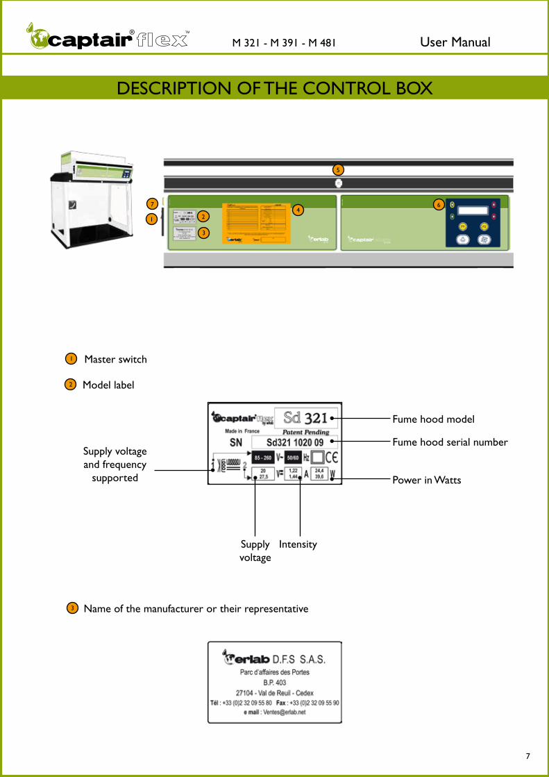
Master switch
Model label
Name of the manufacturer or their representative
1
2
3
1 2
3
4
5
6
Fume hood model
Fume hood serial number
Power in Watts
IntensitySupply voltage
Supply voltage and frequency
supported
DESCRIPTION OF THE CONTROL BOX
7

User ManualM 321 - M 391 - M 481 TM
8
4
5
6
Valipass® form: Refer to the Valiquest® section for details.
Control panel
Sampling port for the manual filter saturation test or for an ambient air sensor when the machine is equipped with the Molecode™ S option.
Yellow indicator light
Green indicator light
Red indicator light
Red indicator light
Digital display screen
Confirmation buttonNavigation button
Ventilation switch
Internal light switch
For information on the various scenarios related to the triggering of the device’s indicator lights and audible alerts, refer to the EVENT ALERTS section
of the FIRST START-UP chapter.
7 Fuse tag.
User ManualM 321 - M 391 - M 481 TM
9
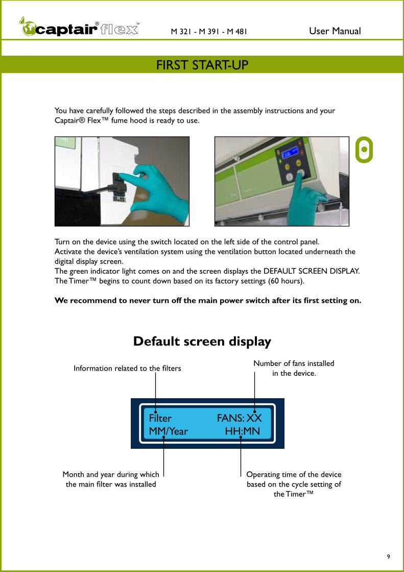
Default screen display
Information related to the filters
Month and year during which the main filter was installed
Number of fans installed in the device.
Operating time of the device based on the cycle setting of
the Timer™
Filter FANS: XXMM/Year HH:MN
Turn on the device using the switch located on the left side of the control panel.Activate the device’s ventilation system using the ventilation button located underneath the digital display screen.The green indicator light comes on and the screen displays the DEFAULT SCREEN DISPLAY.The Timer™ begins to count down based on its factory settings (60 hours).
We recommend to never turn off the main power switch after its first setting on.
You have carefully followed the steps described in the assembly instructions and your Captair® Flex™ fume hood is ready to use.
FIRST START-UP

User ManualM 321 - M 391 - M 481 TM
10
The Timer™The Timer™ keeps track of the amount of time that your Captair® Flex™ fume hood has been in operation in order to remind the user when it is necessary to carry out a periodic filter saturation test.
The default setting (factory setting) is 60 hours (as required by NF X 15-211: 2009 stan-dard).
An alarm will alert the user to check that the filter is still able to function properly.
A pre-warning alarm may go off between 0 and 10 hour(s) before the Timer™ alarm (according to factory settings).
Activation / Deactivation:It is possible to activate or deactivate the Timer™ and its pre-warning alarm.To make use of this functionality please refer to the section on “Navigating the digital display screen.”
In order to guarantee that your device functions properly and in order to ensure your safety, your Captair® Flex™ fume hood is equipped with a monitoring system linked to the air flow parameters and to the device’s Flex™ technology.
Event 1:
Fan control problem
Event conditions:The fume hood does not reach the proper number of rotations per minute (RPMs) wi-thin a period of ten seconds after the ventilation system has been started.
This section describes all of the audible and visual alerts triggered by the alarms included in your Captair® Flex™ fume hood.
Solution:Contact your maintenance service as quickly as possible.
FAN CONTROL FAILURE
Display screen
Event alerts
Alarm type
Yellow indicator light on, constantIntermittent audible alarm

User ManualM 321 - M 391 - M 481 TM
11
Event 2:
Fan out of order
Event conditions:The rotation speed of the fan is less than 700 RPM.
FAN OUT OF ORDER
Display screen Alarm type
Solution : Contact your maintenance service as quickly as possible.
Solution : The concentration at the exhaust of a filter nearing its saturation point can build up very quickly. Consider replacing the filter.
Event 3:
Solvent detected in the sampling chamber
Event conditions:The detection limit of the Molecode™ S unit has been reached during 5 min.
FILTER NEAR END OF LIFE
Display screen Alarm type
Red indicator lights on, constantContinuous audible alarm
Yellow indicator light on, constantIntermittent audible alarm

User ManualM 321 - M 391 - M 481 TM
12
Event 4:
Solvent detected 2
Event conditions: The detection limit of the Molecode™ S unit has been surpassed.
CHANGE FILTER(S)
Display screen Alarm type
Solution : It is necessary to replace the filter.Please contact your maintenance service.
Solution : Press the OK button to deactivate the alarm.Identify the source of the pollution.
Event 5:
Pollutant detected in the ambient air of the laboratory
Event conditions: The ambient air sensor on the front detects that pollution is likely in the ambient air of the laboratory.
LABORATORY POLLUTION
Display screen Alarm type
Red indicator light on, constantContinuous audible alarm
Red indicator light on, blinkingContinuous audible alarm
User ManualM 321 - M 391 - M 481 TM
13
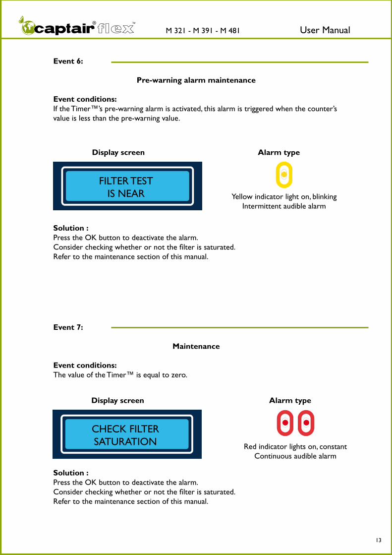
Event 6:
Pre-warning alarm maintenance
Event conditions: If the Timer™’s pre-warning alarm is activated, this alarm is triggered when the counter’s value is less than the pre-warning value.
FILTER TEST IS NEAR
Display screen Alarm type
Solution : Press the OK button to deactivate the alarm.Consider checking whether or not the filter is saturated.Refer to the maintenance section of this manual.
Event 7:
Maintenance
Event conditions:The value of the Timer™ is equal to zero.
CHECK FILTER SATURATION
Display screen Alarm type
Solution : Press the OK button to deactivate the alarm.Consider checking whether or not the filter is saturated.Refer to the maintenance section of this manual.
Yellow indicator light on, blinkingIntermittent audible alarm
Red indicator lights on, constantContinuous audible alarm

User ManualM 321 - M 391 - M 481 TM
14
DEFAULT SCREEN DISPLAY
Information related to the filters
Month and year during which the main filter was installed
Number of fansinstalled in the device
Operating time of the device based on the cycle setting of
the Timer™
Filter FANS: XXMM/Year HH:MN
ACCESSING THE MENUS
To access the menus of the screen, press down on the navigation and confirmation buttons
simultaneously.The menus will appear when the buttons are
released.
NAVIGATING THE DIGITAL DISPLAY SCREEN

User ManualM 321 - M 391 - M 481 TM
15
Notes:Allows the user to view the sta-tus of the fume hood. Press the confirmation button to access the contents of the menu.
Allows the user to modify the parameters of the screen display language.Press the confirmation button to access the contents of the menu.
Allows the user to update information after testing for filter saturation.Press the confirmation button to access the contents of the menu.
Allows the user to modify the limit settings of the Molecode™ S detection sensor.Press the confirmation button to access the contents of the menu.
Allows the service engineer to set the ventilation flow rate. Protected by an access code. Press the confirmation button to access the contents of the menu.
Allows the user to activate or deactivate the Timer™. Press the confirmation button to access the contents of the menu.
Allows the service engineer to access the device’s configuration. Protected by an access code.Press the confirmation button to access the contents of the menu.
Allows the user to exit the main menu.Press the confirmation button to display the default screen display.
1 Main Menu
MAIN MENU>Hood State
1-1
Hood State>Set Language
1-2
Set Language>Test filter
1-3
Test filter >Set Threshold
1-4
Set Threshold>Set Setpoint
1-5
Set Setpoint>Set Timer
1-6
Set Timer>Man. Menu
1-7
Man. Menu>Exit
1-8

User ManualM 321 - M 391 - M 481 TM
16
Notes :
This number corresponds to the number of fans detected by the device.It may be between 1 and 4 de-pending on the Captair® Flex™ model in question. (Refer to the technical specifications listed at the end of the manual.)
Indicates the presence or absence of the Molecode™ S option on your device.
This number indicates the sensitivity on the Molecode™ S Reference sensor included on your device. If the device is not equipped with a Molecode™, the contents of this screen are not visible.
This number indicates the sensiti-vity on the Molecode™ S Mesure sensor included on your device. If the device is not equipped with a Molecode™, the contents of this screen are not visible.
RPM: rotations / minute. This number indicates the rotation speed of each fan. It may be between 0 and 3000 depen-ding on the Flex™ technology installed in your device and on the factory settings. The rotation speed must be the same for each fan installed, +/- 5%.
Display the Hood Stat menu.
1-1 Hood State
1-1-1
1-1-2
1-1-4
1-1-5
1-1-3-1
Threshold SensorM : XXX
Threshold SensorR : XXX
Number of fan XX
RPM01:XXXX 02:XXXX03:XXXX 04:XXXX
MAIN MENU>Hood State
1-1-3-2
Solvent SensorYES
Solvent SensorNON
User ManualM 321 - M 391 - M 481 TM
17
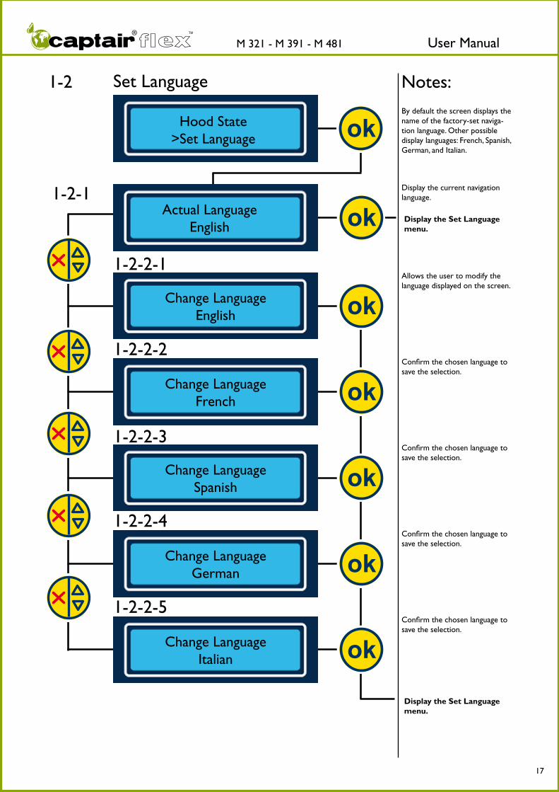
By default the screen displays the name of the factory-set naviga-tion language. Other possible display languages: French, Spanish, German, and Italian.
Notes:
Allows the user to modify the language displayed on the screen.
Confirm the chosen language to save the selection.
Display the current navigation language.
Display the Set Language menu.
Display the Set Language menu.
Confirm the chosen language to save the selection.
Confirm the chosen language to save the selection.
Confirm the chosen language to save the selection.
Set Language1-2
1-2-1 Actual Language
English
Change Language English
Change Language French
Change Language Spanish
Change LanguageGerman
Change Language Italian
Hood State>Set Language
1-2-2-1
1-2-2-2
1-2-2-3
1-2-2-4
1-2-2-5

User ManualM 321 - M 391 - M 481 TM
18
Notes:
N.B.: accessing this menu interrupts the ventilation system of your device. It is strongly recommended to access this menu after the filter saturation tests have been performed. Press the confirm button to proceed to the next step.
Displays the sensitivity value of the current sensor as sto-red in the device’s memory or previously modified.If the Molecode™ S is not installed on the device, screens 1-3-5, 1-3-6, 1-3-7 and 1-3-8 do not display.
Allows the user to adjust the sensitivity value of units (M & R) after a new filter has been installed. Scroll through the numbers using the scroll button and confirm each digit using the confirmation button.
Confirm the previously selected value.
Displays the month, year, and operating time of the device after a new filter has been installed in the Manufacturer menu.
Parameter reset menu after a new filter has been installed.
Allows the user to confirm the installation date of the new filter and to reset the Timer™ if the Timer™ is ac-tivated according to factory settings. If the Timer™ is not activated, “H:Mn” is not displayed on the screen.
Allows the user to indicate the new filter installation date.
Display the Test filter menu.
Test filter1-3
1-3-1 Test filter New filter
New filterMonth/Year H:Mn
Confirm ? Month/Year H:Mn
Date : MM XX YY XXXX
Threshold Sensor M Value : XXXX
Threshold Sensor R Value : XXXX
Confirm Value
Confirm Value
Set Language>Test filter
1-3-7
1-3-8
1-3-6
1-3-5
1-3-4
1-3-3
1-3-2
Display the 1-3-2-1 menu

User ManualM 321 - M 391 - M 481 TM
19
Notes :N.B.: Accessing this menu inter-rupts the ventilation system of your device. Press the confirm button to proceed to the next step.
After verifying the condition of the filter via a saturation test, display the installation date and operating time of this filter.
By pressing the confirm button, the Timer™ is reset according to the factory configuration if the Timer™ is activated.
Display the Test filter menu.
Test filter1-3
1-3-2-1 Test filter
Good Filter
Good Filter Month/Year H:Mn
Confirm ? Month/Year H:Mn
1-3-2-2
1-3-2-3

User ManualM 321 - M 391 - M 481 TM
20
Notes:
N.B.: accessing this menu inter-rupts the ventilation system of your device. Press the confirm button to proceed to the next step. IMPORTANT: this menu only appears if the device is equipped with a Molecode™ S.
Displays the sensitivity value of the Molecode™ S units ( M & R) as configured in the factory or previously modified. Scroll through the numbers using the scroll button and confirm each digit using the confirmation button.
Allows the user to confirm the selected value.
Display the Set Threshold menu
Set Threshold1-4
1-4-1
1-4-3
Threshold Sensor M Value : XXXX
Threshold Sensor R Value : XXXX
Confirm XXXX ?
Confirm XXXX ?
1-4-2
1-4-4
Test filter >Set Threshold

User ManualM 321 - M 391 - M 481 TM
21
Notes:
N.B.: the contents of this menu are protected by an access code. Contact your maintenance service for additional information.
By default, the screen displays 00000000. Using the scroll but-tons, select the appropriate digit in the active box and press the confirm button to move to the next digit.
Confirm the selected access code.
Allows the user to enter the device’s ventilation settings based on the Flex™ technology installed in your fume hood. This setting may be between 0 and 3000 RPM (rotations/minute). Using the scroll buttons, select the appropriate digit in the active box and press the confirm button to move to the next digit. Confirm the previously selected setting.
Display the Set Setpoint menu.
Set Setpoint1-5
1-5-1 Access Code
00000000
Access Code ? 00000000
Fan Setpoint Value : XXXX RPM
Confirm Setpoint XXXX ?
Set Threshold>Set Setpoint
1-5-2
1-5-3
1-5-4

User ManualM 321 - M 391 - M 481 TM
22
Notes:
Display the Set Timer menu.
Display the Set Timer menu.
This menu allows the user to ac-tivate or deactivate the Timer™.
Displays the fact that the Timer™ is activated.
Confirm activation of the Timer™.
Displays the fact that the Timer™ is deactivated.
Confirm deactivation of the Timer™.
Set Timer1-6
1-6-1-1 Set Timer Timer ON
Confirm Timer ON ?
1-6-2-1
1-6-2-2
Set Timer Timer OFF
Confirm Timer OFF ?
Set Setpoint>Set Timer
1-6-1-1

User ManualM 321 - M 391 - M 481 TM
23
Notes:
N.B.: the contents of this menu are protected by an access code. Contact your maintenance ser-vice for additional information.
To enter the access code, scroll through the numbers in the active box using the scroll button. Press the confirm button to proceed to the next box. Once the code is entered, confirm the code using the OK button.
Indicates the number of fans detected by the CPU card when the device is first plugged in.
Indicates that the CPU card detects the Molecode™ S option when the device is first plugged in.
Counts the number of resets to the New filter mode (menu 1-3-1-1).
Counts the number of resets to the Good filter mode (menu 1-3-2-1).
Allows the user to access menu 1-7-7.
Réinitialise le compteur
Réinitialise le compteur
Manufacturer Menu1-7
1-7-1 Access Code ?
00000000
ManufacturerSet up
ManufacturerFans : XX
Manufacturer New. Filter XXX
ManufacturerFilter good XXX
Set Timer>Man. Menu
1-7
1-7-2
1-7-3
1-7-4-1
1-7-5
1-7-6
ManufacturerMolecode : YES
Manufacturer Molecode : NO
1-7-4-2

User ManualM 321 - M 391 - M 481 TM
24
Notes :
Allows the user to activate or deactivate the Timer™.
Allows the user to set the Timer™’s time value if the Timer™ is activated. Possible values: from 1 to 250 hours. Scroll through the numbers in the active box using the scroll button and confirm the selected value using the confirma-tion button.
Allows the user to activate or deactivate the pre-warning alarm for the filter saturation test.
Allows the user to set the point at which the pre-warning alarm is triggered. Possible values: between 0 and 10 hour(s). Scroll through the numbers in the active box using the scroll button and confirm the selected value using the confirmation button.
Allows the user to access menu 1-7-11.
Manufacturer Menu1-7
ManufacturerTimer Value XXX
Manufacturer Pre alarm XX
1-7-7-1 1-7-7-2 ManufacturerTimer OFF
ManufacturerTimer ON
1-7-8
1-7-9-1 1-7-9-2 ManufacturerPre alarm OFF
ManufacturerPre alarm ON
1-7-10

User ManualM 321 - M 391 - M 481 TM
25
Notes:Allows the user to modify the language displayed on screen.
Allows the user to modify the language displayed on screen.
Allows the user to modify the language displayed on screen.
Allows the user to modify the language displayed on screen.
Allows the user to modify the language displayed on screen.
Allows the user to access menu 1-7-12.
Manufacturer Menu1-7
ManufacturerLang. English
CFG UsineLag. Français
FabricanteIdiioma Español
ProduttoreLingua italiano
HerstellerSprache Deutsh
1-7-11-2
1-7-11-1
1-7-11-3
1-7-11-4
1-7-11-5
User ManualM 321 - M 391 - M 481 TM
26
Notes:
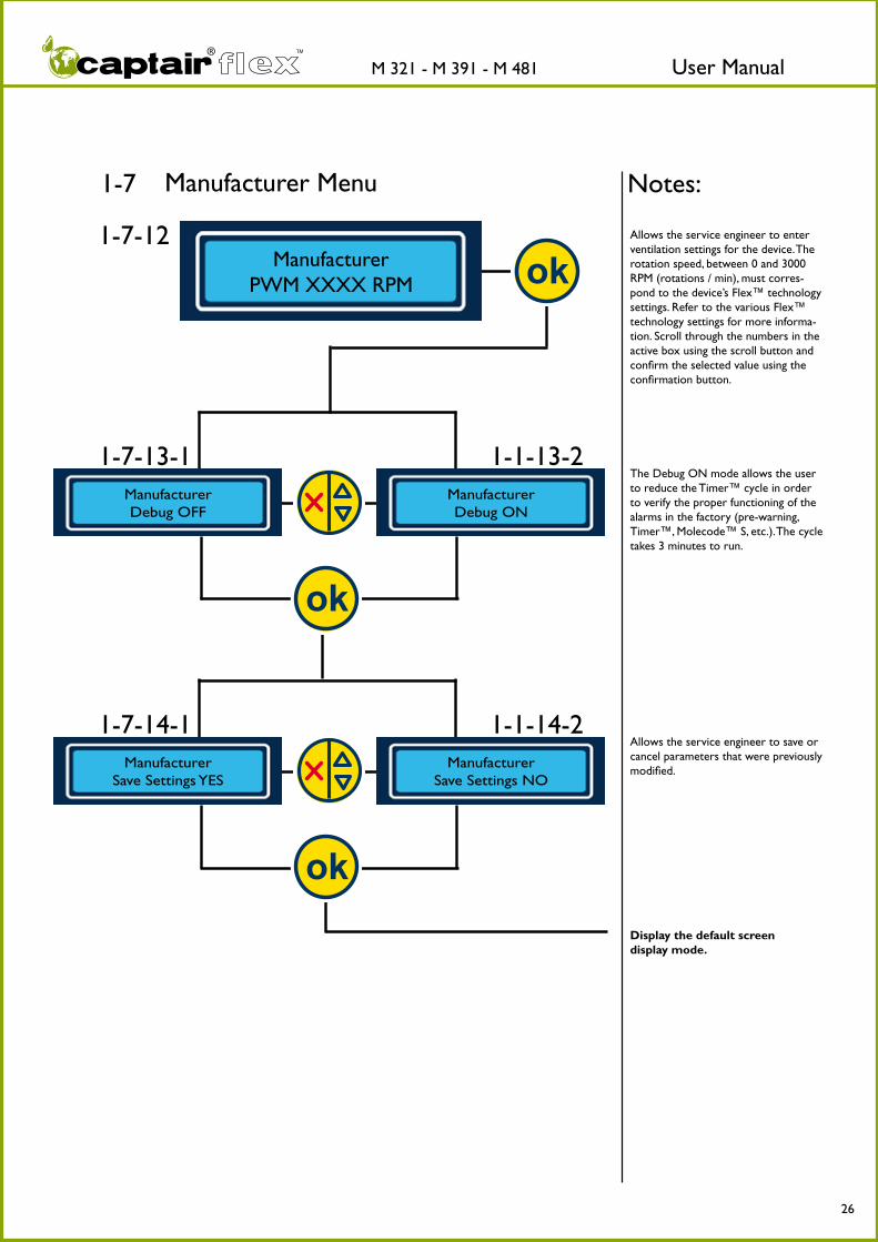
Display the default screen display mode.
Allows the service engineer to enter ventilation settings for the device. The rotation speed, between 0 and 3000 RPM (rotations / min), must corres-pond to the device’s Flex™ technology settings. Refer to the various Flex™ technology settings for more informa-tion. Scroll through the numbers in the active box using the scroll button and confirm the selected value using the confirmation button.
The Debug ON mode allows the user to reduce the Timer™ cycle in order to verify the proper functioning of the alarms in the factory (pre-warning, Timer™, Molecode™ S, etc.). The cycle takes 3 minutes to run.
Allows the service engineer to save or cancel parameters that were previously modified.
Manufacturer Menu1-7
1-7-12 Manufacturer
PWM XXXX RPM
1-7-13-1 1-1-13-2 ManufacturerDebug OFF
ManufacturerDebug ON
1-7-14-1 1-1-14-2 Manufacturer
Save Settings YESManufacturer
Save Settings NO

User ManualM 321 - M 391 - M 481 TM
27
Protecting yourself- Via the E.S.P. program (Erlab Safety Program)- Via AFNOR NF X 15-211: 2009 standard

User ManualM 321 - M 391 - M 481 TM
28
erlab® safety program
THE ® PROGRAM—KEEPING YOU SAFE
CERTIFIED INSTALLATION
MANIPULATION IN TOTAL SAFETY
PERMANENT FOLLOW-UP
UNIT RECONFIGURATION ACCORDING TO
THE PROTECTION NEEDS
PREVENTIVE CONTROL AND MAINTENANCE
DETERMINATION OF ERGONOMIC NEEDS
RISK ASSESSMENT
DETERMINATION OF PROTECTION NEEDS
Call your ESP® specialist today and configure this unique Captair® Flex™
solution to your requirements.www.erlab.com
1
2
3
The service:Certify and secure the usage
framework at installationWhen you receive your Captair® filtering fume hood, a usage certificate will give precise details on the chemicals to be used, the filter type and an estimation of its lifetime expectancy, for which your Captair® filtering fume hood has been validated. This certificate is a permanent reminder to the user or the safety officer of the data relating to their protection.
The service: A constant monitoring of your filtering fume hood.
Periodically (about every six months), the E.S.P.® agent will contact you to make sure that you have not changed your handlings and that the filter is still active. The E.S.P.® agent will show you how to perform step by step filter saturation tests and also the procedure for filter replacement. During this contact, if the E.S.P. ® agent finds that there is a change in chemical handlings, you will be asked to complete a new questionnaire (see step 1). After review, a new certificate for use (to be placed on the front of the filtering fume hood) naming the approved chemicals will be sent to you to ensure that your chemical handlings are still performed within optimum safety conditions.
The service: Determine the most appropriate filtering fume
hood for total safety during your handlingsAssisted by an E.S.P.® agent, you complete the investigation questionnaire, which precisely describes your intended chemical handlings. Our validation laboratory specialists will recommend the appropriate filtration fume hood and filter type. Personalized advice and accurate answer within 48 hours. A certificate validating the handling is supplied: real commitment of the manufacturer to the safety of the operator.
A long-lasting commitment by erlab® to the safety of the operator
An essential part of user safety, our laboratory’s mission is to assess the interactive behavior of molecules and their interactive effect with the Flex™ filtration technology.Based on this scientific investigation, your E.S.P.® specialist will recommend the most appropriate unit, define the adapted filtration column and the enclosure design and ensure a complete protection to the user. After installation, your E.S.P.® specialist will provide you with a constant monitoring of the unit regarding the handlings performed.

User ManualM 321 - M 391 - M 481 TM
29
THE SERVICE
IDENTIFIES THE FILTERING FUME HOOD BEST SUITED FOR YOUR APPLICATIONS
Risk analysis and identification of protection needs
A
B
C
D
1 4 5 6 7 8 92 3
This service, which is completely free of charge, is offered to you before the purchase of your fume hood.You may contact your E.S.P. agent at any time to reconfigure the Flex™ technology of your filtering fume hood. The fume hood can be modified according to the protection needs and the environment of your laboratory.
This service is available online at www.erlab.com or at one of our commercial branches.
User ManualM 321 - M 391 - M 481 TM
30
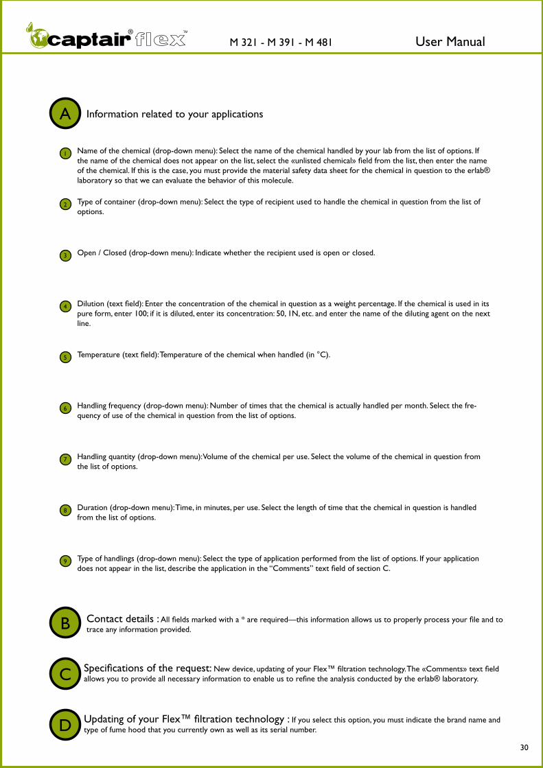
A Information related to your applications
1 Name of the chemical (drop-down menu): Select the name of the chemical handled by your lab from the list of options. If the name of the chemical does not appear on the list, select the «unlisted chemical» field from the list, then enter the name of the chemical. If this is the case, you must provide the material safety data sheet for the chemical in question to the erlab® laboratory so that we can evaluate the behavior of this molecule.
2 Type of container (drop-down menu): Select the type of recipient used to handle the chemical in question from the list of options.
3 Open / Closed (drop-down menu): Indicate whether the recipient used is open or closed.
4 Dilution (text field): Enter the concentration of the chemical in question as a weight percentage. If the chemical is used in its pure form, enter 100; if it is diluted, enter its concentration: 50, 1N, etc. and enter the name of the diluting agent on the next line.
5 Temperature (text field): Temperature of the chemical when handled (in °C).
6 Handling frequency (drop-down menu): Number of times that the chemical is actually handled per month. Select the fre-quency of use of the chemical in question from the list of options.
7 Handling quantity (drop-down menu): Volume of the chemical per use. Select the volume of the chemical in question from the list of options.
8 Duration (drop-down menu): Time, in minutes, per use. Select the length of time that the chemical in question is handled from the list of options.
9 Type of handlings (drop-down menu): Select the type of application performed from the list of options. If your application does not appear in the list, describe the application in the “Comments” text field of section C.
Contact details : All fields marked with a * are required—this information allows us to properly process your file and to trace any information provided.B
Specifications of the request: New device, updating of your Flex™ filtration technology. The «Comments» text field allows you to provide all necessary information to enable us to refine the analysis conducted by the erlab® laboratory.C
Updating of your Flex™ filtration technology : If you select this option, you must indicate the brand name and type of fume hood that you currently own as well as its serial number.D

User ManualM 321 - M 391 - M 481 TM
31
8
7
6
5
4
3
2
9
10
11
12
13
14
1List of chemicals authorized by the erlab laboratory for use with your fume hood in accordance with the information provided via the Valiquest® questionnaire of the E.S.P. ® (Erlab Safety Program) program.
Device model and Flex™ technology appropriate for your applications.
Serial number of your device.
Date of first use of the filter.
The reference number of your E.S.P. ® file.
Expected life time of the filter.
Filter saturation detection: the chemical in question, which should be the subjectof the saturation detection test.
Part number of the color coded tube made by this manufacturer.
Part number of the color coded tube made by this manufacturer.
Part number of the color coded tube made by this manufacturer.
Molecode™ S setting for the detection of the chemical listed in field 8.
Installation of the Molecode™ S broad-spectrum automatic detector, if applicable.
Date of issue of the Valipass® certificate.
User contact details
CERTIFIES AND CONFIRMS APPROPRIATE USE OF THE FUME HOOD FOR INSTALLATION
8
7
6
5
4
3
21
9
10
11
12
13
14
THE SERVICE
User ManualM 321 - M 391 - M 481 TM
32
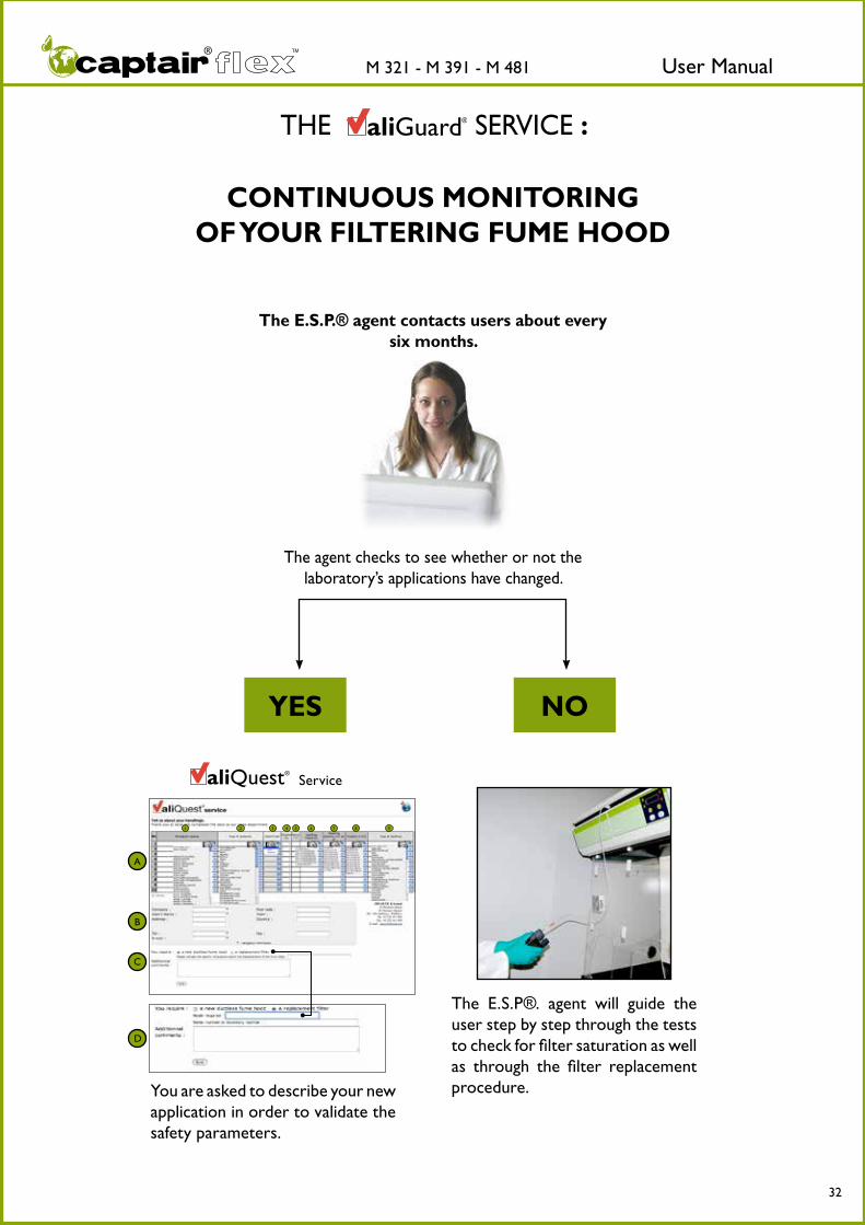
THE SERVICE :
CONTINUOUS MONITORING OF YOUR FILTERING FUME HOOD
The E.S.P®. agent will guide the user step by step through the tests to check for filter saturation as well as through the filter replacement procedure.You are asked to describe your new
application in order to validate the safety parameters.
The E.S.P.® agent contacts users about every six months.
The agent checks to see whether or not the laboratory’s applications have changed.
YES NO
A
B
C
D
1 4 5 6 7 8 92 3
Service

User ManualM 321 - M 391 - M 481 TM
33
AFNOR NF X 15-211: 2009 standard
Filtration efficiency
Containment efficiency
Air face velocity
The classes established by the standard
Classification according to filtration type
The filtration efficiency
Class 1 Class 2Normal operation
phaseEmissions concentration at the filter exhaust must be lower than 1%
of the TLV
Detection phase The concentration at the filter exhaust must
be lower than 1% of the TLV, and the automatic saturation detector must warn the user
The concentration at the filter exhaust must be lower than 50% of the TLV
Safety operation phase
The concentration at the filter exhaust must be lower than 50% of the TLV ; its duration must
not be lower than 1/12 of the normal operation phase duration.
It is defined by the filter capacity to retain noxious molecules manipulated within the enclosure and qualifies the quality of the recirculated air at the filter exhaust.
Class 1 Class 2Filtration fume hood with safety reserve Filtration fume hood without safety reserve
one main filtration level and one safety filtration level One filtration level
Denominations according to the NF X 15 211:2009 standard
Denominations equivalence for the erlab® products
Particles filtration* Type P Type P
Vapours filtration** Type V Type C
Particles and vapours filtration** Type PV Type PC
* : The particulate filter must be at least of H14 type according to the NF EN 1822-1 standard** : The filters for vapours must be submitted to two successive performance tests with Cyclohexane and Isopropanol for the filters designed to retain Volatile Organic Compounds (VOC). Another test for the acid vapours is carried out with Hydrochloric acid.
Appointed by the AFNOR, the Union de Normalisation de la Mécanique (UNM), composed of a college of experts (INRS, national organizations, professional syndicates), has established the AFNOR NF X 15-211 : 2009 standard. This standard applies to filtration fume hoods (also named recirculatory fume hoods or ETRAF) designed for research, analysis, education works,…. for all laboratories where chemicals subjected to professional exposure limit values (OEL or TLV) are manipulated. This text imposes performances criteria linked to:
As well as a specific documentation attached with each filtration fume hood.
Example of test carried out on a Captair® Flex™ XL 714, equipped with BE+ filters in class 1
Isopropanol Cyclohexane HCL (35%)
2250 gr 3204 gr 7862 gr
The retention capacities recorded during the tests performed on our filters demonstrate the technical performance developed by Erlab®.These results ensure a very high protection level to the Captair® Flex™ users.

User ManualM 321 - M 391 - M 481 TM
34
Containment efficiency of the enclosure
Air face velocity
The documentation
Every Erlab® filtration fume hood is in compliance with these safety criteria.
Erlab® products are in compliance with the following standards which guarantee your total protection.
The international standards
France : AFNOR NF X 15-211 : 2009 USA : ANSI/AIHA Z9.5 ASHRAE 110 : 1995
• The chemical name, its formula, its CAS number, its boiling point, its molecular weight, its saturation vapour pressure• The appropriate filter reference and its retention capacity during the normal operation phase• The type of saturation detection system for the filter(s)
• The maximum quantity of the chemical that can be introduced within the enclosure• The name of the test laboratory having performed the test
To prove this efficiency, a test is carried out following the protocol described in the standard.SF6 (Sulfur Hexafluoride) tracer gas emissions are made into the enclosure. A grid composed of sensors is placed in front of the working openings. Some samplings are done at the grid. Based on the emitted gas concentration and the samplings done (which will allow the determination
of an average operator exposure to this tracer gas), it is possible to determine a containment performance level of the filtration fume hood.The containment threshold specified by the NFX 15-211:2009 standard imposes a maximum concentration of 0.1 ppm of SF6 gas at the measuring points on the grid.
It represents the fume hood capacity to create a dynamic barrier between the operator and the handling.
For filtration fume hoods with fixed front panel, the air face velocity at any point of the front openings must be between 0.4 and 0.6 m/s. They must be equipped with a permanent monitoring system for the air face velocity which also acts as a real time containment indicator.
It is defined by the fume hood capacity to maintain chemical vapors or particles within the enclosure without any propagation in the laboratory environment.
Filtration fume hoods must be delivered with a booklet containing an exhaustive list of chemicals, certified by the manufacturer, that can be handled into the filtering fume hood in the conditions described in the AFNOR NF X 15-211: 2009 standard. The following information must be indicated in the booklet for each chemical listed:
Erlab® has created its own booklet called the CHEMICAL LISTING. This booklet contains a list of approved chemicals indicating analysis data for about 700 molecular substances commonly used in laboratories. This booklet is delivered with each unit, as per the requirements of the AFNOR NF X 15-211: 2009 standard.

User ManualM 321 - M 391 - M 481 TM
35
Maintenance- Monitoring air face velocity- Manually detecting filter saturation- Automatically detecting filter saturation- Replacing the filters- The revolving system- Cleaning and maintenance

User ManualM 321 - M 391 - M 481 TM
36
The anemometer provided with your Captair® Flex™ fume hood allows the user to constantly monitor the face velocity.If the anemometer is not installed during assembly, please install this device according to the steps listed in the installation instructions provided with your fume hood.
When reading the face velocity, first be sure to check that the leveling bubble on the anemometer is positioned correctly. To ensure proper movement of the strip, the anemo-meter must be level. The air face velocity must be between 0.4 and 0.6 m/s (as required by AFNOR NF X 15-211: 2009 standard).
What should you do if the strip does not move or if its movement is irregular?
First of all, verify that the fume hood’s ventilation system is turned on.
If the strip’s movement is highly irregular, verify that the strip is correctly positioned in the housing located within the anemometer as shown in the diagrams below. The two pins of the strip must be correctly positioned in the support slots.
2 31
Leveling bubble
Range of movement of the air speed indicator strip.
Monitoring air face velocity

User ManualM 321 - M 391 - M 481 TM
37
To carry out a manual filter saturation test, you need the following equipment:- a pump (not provided)- a flexible silicone tube (provided)- the chemical with which you will be testing (not provided)- a color coded tube suitable for detecting this chemical (not provided)The list of equipment not provided by erlab® may be purchased from various manufacturers including Gastec, Draeger, Kitagawa, RAE System, or their licensed distributors.
Your application was analyzed and validated by the erlab® laboratory as part of the erlab Safety Program (E.S.P.). During this validation, the erlab® laboratory used the information provided to determine the chemical that must be the subject of the molecular filter satu-ration test. You have access to this information at any time on your Valipass® certificate.
Power on you Captair® Flex™ fume hood and turn on the ventilation system.
7
Verify the name of the chemical for which you will carry out the filter saturation test using the manual method.
MANUALLY DETECTING FILTER SATURATION

User ManualM 321 - M 391 - M 481 TM
38
Evaporate a sufficient amount of the chemical for testing purposes within the enclosure. To do this, soak a rolled up piece of cloth in a container placed inside the enclosure of your Captair® Flex™ fume hood.
Connect one end of the silicone tube to the sampling port located on the control panel of your Captair® Flex™ fume hood.
Break off the two ends of the color coded tube. Each pump is generally equipped with a system that allows the tubes to be broken without any risk to the operator or maintenance technician.
Connect the broken tube to the pump, being careful to verify that the tube is inserted in the correct direction. The color coded tubes are marked with this information.
38
User ManualM 321 - M 391 - M 481 TM
39
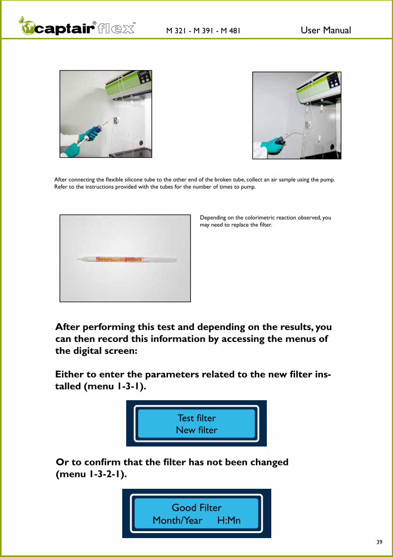
After connecting the flexible silicone tube to the other end of the broken tube, collect an air sample using the pump. Refer to the instructions provided with the tubes for the number of times to pump.
After performing this test and depending on the results, you can then record this information by accessing the menus of the digital screen:
Either to enter the parameters related to the new filter ins-talled (menu 1-3-1).
Or to confirm that the filter has not been changed (menu 1-3-2-1).
Depending on the colorimetric reaction observed, you may need to replace the filter.
Test filter New filter
Good Filter Month/Year H:Mn

User ManualM 321 - M 391 - M 481 TM
40
12
Find the setting for the Molecode™ S , automa-tic detection of filter saturation by solvents.
The automatic Molecode™ S detector is automatically activated when the ventilation system of your Captair® Flex™ fume hood is started.
It uses a sensor designed to detect various organic vapors and gases, which, based on the parameters set for the sensor, make it possible to detect saturation of the main filter.
How do you modify the settings of the sensor ?
Before turning on your Captair® Flex™ fume hood for the first time, verify that the de-tector setting corresponds to the code provided by the erlab® laboratory after analyzing and validating your application. This configuration was factory-set using the information provided.
This information is available at any time on your Valipass® form,which is attached to the control panel of your Captair® Flex™ fume hood.
To enter this setting, refer to section 1-5 of the chapter on “Navigating the digital display screen.”
For the detection of a single chemical:Refer to the limits listed on the next page.
MODIFYING THE LIMIT SETTINGS FOR THE UNIT
For the detection of multiple chemicals:Contact your E.S.P.® agent as soon as possible in order to determine the limit value corresponding to your application.
Molecode™ S:
AUTOMATICALLY DETECTING FILTER SATURATION

User ManualM 321 - M 391 - M 481 TM
41
1, 4-Dioxane C4H8O2 123-91-1 3500
1,1,1-Trichloroethane C2H3Cl3 71-55-6 2700
1,1-Dichloroethane C2H4Cl2 75-34-3 2800
1,2-Dibromoethane C2H4Br2 106-93-4 2700
1,2-Dichloroethane C2H4Cl2 107-06-2 2700
1,2-Ethanediol C2H6O2 107-21-1 3100
1-Aminobutane C4H9NH2 109-73-9 2800
1-Butanol C4H10O 71-36-3 4000
1-Chloro butane C4H9Cl 109-69-3 3000
1-Propanol C3H8O 71-23-8 4100
2, 2'-Dichlorodiethyl ether C4H8OCl2 111-44-4 2800
2, 4-Dimethyl pentane C7H16 108-08-7 3600
2,4-Dimethyl-3-pentanone C7H14O 565-80-0 2800
2,6-Dimethyl-4-heptanone C9H18O 108-83-8 3500
2-Amino butane C4H9NH2 13952-84-6 2800
2-Butanol C4H10O 78-92-2 4200
2-Butanone C4H8O 78-93-3 4000
2-Butenal C4H6O 4170-30-3 3600
2-Butoxyethanol C6H14O2 111-76-2 2700
2-Chloroacetaldehyde C2H3OCl 107-20-0 2700
2-Chloroethanal C2H3OCl 107-20-0 2700
2-Chloroethanol C2H5OCl 107-07-3 3000
2-Chloroethyl alcohol C2H5OCl 107-07-3 3000
2-Ethoxyethanol C4H10O2 110-80-5 3500
2-Furylmethanol C5H6O2 98-00-0 3100
2-Heptanone C7H14O 110-43-0 4300
2-Hexanone C6H12O 591-78-6 2800
2-Hydroxymethylfuran C5H6O2 98-00-0 3100
2-Methyl-1,3-butadiene C5H8 78-79-5 2800
2-Methyl-1-propanol C4H10O 78-83-1 2800
2-Methylbutane C5H12 78-78-4 3500
2-Methylpropyl acetate C6H12O2 110-19-0 3000
2-Methylpropyl ester of acetic acid C6H12O2 110-19-0 3000
2-Pentanone C5H10O 107-87-9 4000
2-Pentanone C5H10O 107-87-9 4000
2-Phenyl propane C9H12 98-82-8 3000
2-Propanol C3H8O 67-63-0 4100
2-Propanone C3H6O 67-64-1 4200
2-Propen-1-ol C3H6O 107-18-6 2800
2-Propenol C3H6O 107-18-6 2800
2-Propyl acetate C5H10O2 108-21-4 3000
3-Chloro-1-propene C3H5Cl 107-05-1 2800
3-Pentanone C5H10O 96-22-0 4500
4-Methyl 2-pentanone C6H12O 108-10-1 2800
4-Methyl-2-pentanone C6H12O 108-10-1 2800
4-tert-Butyl toluene C11H16 98-51-1 2800
5-Methyl-3-Heptanone C2H6O2 541-85-5 3500
Absolute alcohol C2H6O 64-17-5 4500
Acetaldehyde C2H4O 75-07-0 2800
Acetic acid C2H4O2 64-19-7 2800
Acetone C3H6O 67-64-1 4200
Acetonitrile C2H3N 75-05-8 3000
a-Chlorotoluene C7H7Cl 100-44-7 2700
Alcohol C2H6O 64-17-5 4500
Aldehyde ethylique C2H4O 75-07-0 2800
Allyl alcohol C3H6O 107-18-6 2800
Allyl chloride C3H5Cl 107-05-1 2800
Allylglycidylether C6H10O2 106-92-3 2800
Allylic alcohol C3H6O 107-18-6 2800
Aminocyclohexane C6H11NH2 108-91-8 2700
Aminoethane C2H7N 75-04-7 2700
Ammonia NH3 7664-41-7 2600
Ammonium hydroxyde sol NH4OH 7664-41-7 2600
Amyl alcohol n C5H12O 71-41-0 3200
Azine C5H5N 110-86-1 2700
Benzene chloride C6H5Cl 108-90-7 2700
Benzyl chloride C7H7Cl 100-44-7 2700
beta-Methyl acrolein C4H6O 4170-30-3 3600
beta-Methylpropyl ethanoate C6H12O2 110-19-0 3000
Bicyclopentadiene C10H12 77-73-6 2800
Bromoethane C2H5Br 74-96-4 2700
Bromoform CHBr3 75-25-2 2800
Butyl acrylate C7H12O2 141-32-2 2800
Butyl alcohol C4H10O 71-36-3 4000
Butyl alcohol sec C4H10O 78-92-2 4200
Butyl alcohol ter C4H10O 75-65-0 3000
Butyl carbinol C5H12O 71-41-0 3200
Butyl Cellosolve® C6H14O2 111-76-2 2700
Butyl ether C8H18O 142-96-1 3500
Butyl glycol C6H14O2 111-76-2 2700
Butyl lactate C7H14O3 138-22-7 3000
Butyl metacrylate C18H14O2 97-88-1 2800
Butyl vinyl ether C6H12O 111-34-2 3500
Butyl vinyl ether C6H12O 111-34-2 3500
Butylene hydrate C4H10O 78-92-2 4200
BVE C6H12O 111-34-2 3500
Carbon disulfide CS2 75-15-0 2600
Cellosolve® C4H10O2 110-80-5 3500
Chlorobenzene C6H5Cl 108-90-7 2700
Chlorothene C2H3Cl3 71-55-6 2700
CHEMICAL NAME FORMULA CAS Number Molecode™ settingCHEMICAL NAME FORMULA CAS Number Molecode™
setting
MODIFYING THE LIMIT SETTINGS FOR THE MOLECODE™ S UNIT
You can modify the detection limit of the Molecode™ S at any time.The table at left lists the setting codes to be entered for the detection of a single chemical. To convey this information to the detector, refer to menu 1-4 of the section on “Navigating the digital display screen” in this manual.
Test filter >Set Threshold

User ManualM 321 - M 391 - M 481 TM
42
Cinamene C8H8 100-42-5 2800
Crotonaldehyde C4H6O 4170-30-3 3600
Cumene C9H12 98-82-8 3000
Cumol C9H12 98-82-8 3000
Cyanomethane C2H3N 75-05-8 3000
Cyclohexane C6H12 110-82-7 2800
Cyclohexanol C6H12O 108-93-0 3000
Cyclohexanone C6H10O 108-94-1 3500
Cyclohexene C6H10 110-83-8 3800
Cyclohexyl alcohol C6H12O 108-93-0 3000
Cyclohexyl ketone C6H10O 108-94-1 3500
Cyclohexylamine C6H11NH2 108-91-8 2700
Cyclopentane C5H10 287-92-3 2800
Decane C10H22 124-18-5 2700
Dibutyl ether C8H18O 142-96-1 3500
Dichloropropane 1, 2 C3H6Cl2 78-87-5 4500
Dicyclopentadiene C10H12 77-73-6 2800
Diethamine C4H11N 109-89-7 3200
Diethyl ether C4H10O 60-29-7 3700
Diethyl ketone C5H10O 96-22-0 4500
Diethyl oxide C4H10O 60-29-7 3700
Diethylamine C4H11N 109-89-7 3200
Diethylene dioxide C4H8O2 123-91-1 3500
Diethylene oxide C4H8O 109-99-9 4200
Diisopropyl ketone C7H14O 565-80-0 2800
Diisopropyl ketone C9H18O 108-83-8 3500
Dimethoxymethane C3H8O2 109-87-5 3800
Dimethyl amine C2H7N 124-40-3 2700
Dimethyl benzene (and isomers) C8H10 95-47-6 2800
Dimethyl carbinol C3H8O 67-63-0 4100
Dimethyl ketone C3H6O 67-64-1 4200
Dimethyl sulfoxide C2H6SO 67-68-5 2700
Dimethylacetone C5H10O 96-22-0 4500
Dipropyl ketone C7H14O 123-19-3 4300
DMA C2H7N 124-40-3 2700
DMSO C2H6SO 67-68-5 2700
Ethanal C2H4O 75-07-0 2800
Ethanoic acid C2H4O2 64-19-7 2800
Ethanol C2H6O 64-17-5 4500
Ether C4H10O 60-29-7 3700
Ethyl acetate C4H8O2 141-78-6 4000
Ethyl acrylate C5H8O2 140-88-5 3000
Ethyl alcohol C2H6O 64-17-5 4500
Ethyl benzene C8H10 100-41-4 2800
Ethyl bromide C2H5Br 74-96-4 2700
Ethyl ethanoate C4H8O2 141-78-6 4000
Ethyl ether C4H10O 60-29-7 3700
Ethyl formate C3H6O2 109-94-4 3000
Ethyl ketone C5H10O 96-22-0 4500
Ethyl methyl ketone C4H8O 78-93-3 4000
Ethyl nitrile C2H3N 75-05-8 3000
Ethyl oxide C4H10O 60-29-7 3700
Ethylamine C2H7N 75-04-7 2700
Ethylen chlorhydrin C2H5OCl 107-07-3 3000
Ethylene alcohol C2H6O2 107-21-1 3100
Ethylene bromide C2H4Br2 106-93-4 2700
Ethylene chloride C2H4Cl2 107-06-2 2700
Ethylene chlorohydrin C2H5OCl 107-07-3 3000
Ethylene dibromide C2H4Br2 106-93-4 2700
Ethylene dichloride C2H4Cl2 107-06-2 2700
Ethylene glycol C2H6O2 107-21-1 3100
Ethylene glycol mono ethyl ether C4H10O2 110-80-5 3500
Ethylidene chloride C2H4Cl2 75-34-3 2800
Formic acid CH2O2 64-18-6 2600
Furfuryl alcohol C5H6O2 98-00-0 3100
Furyl carbinol C5H6O2 98-00-0 3100
Glacial acetic acid (pure compound) C2H4O2 64-19-7 2800
Glutaraldehyde C5H8O2 111-30-8 2600
Glycol C2H6O2 107-21-1 3100
Heptan-4-one C7H14O 123-19-3 4300
Hexane C6H14 110-54-3 2800
Hexone C6H12O 108-10-1 2800
Hydroxybenzene C6H6O 108-95-2 2800
Hydroxycyclohexane C6H12O 108-93-0 3000
IPA C3H8O 67-63-0 4100
Isoamyl acetate C7H14O2 123-92-2 3700
Isoamyl alcohol C5H12O 71-41-0 3200
Isobutanol C4H10O 78-83-1 2800
Isobutenyl methyl ketone C6H10O 141-79-7 3000
Isobutyl acetate C6H12O2 110-19-0 3000
Isobutyl alcohol C4H10O 78-83-1 2800
Isobutyl methyl carbinol C6H14O 108-11-2 2700
Isobutyrone C7H14O 565-80-0 2800
iso-Nitropropane C3H7NO2 79-46-9 3000
Isooctane C8H18 540-84-1 3400
Isopentane C5H12 78-78-4 3500
Isopentyl acetate C7H14O2 123-92-2 3700
Isoprene C5H8 78-79-5 2800
Isopropanol C3H8O 67-63-0 4100
Isopropyl acetate C5H10O2 108-21-4 3000
Isopropyl alcohol C3H8O 67-63-0 4100
Isopropyl benzene C9H12 98-82-8 3000
Isopropyl benzene C9H12 98-82-8 3000
Isopropylcarbinol C4H10O 78-83-1 2800
Isopropylideneacetone C6H10O 141-79-7 3000
MEK C4H8O 78-93-3 4000
Mesityl oxide C6H10O 141-79-7 3000
Mesitylene C9H12 108-67-8 4000
Methanoic acid CH2O2 64-18-6 2600
Methanol CH4O 67-56-1 4200
Methyl acetate C3H6O2 79-20-9 3000
Methyl acetone C4H8O 78-93-3 4000
Methyl alcohol CH4O 67-56-1 4200
Methyl benzene C7H8 108-88-3 3000
Methyl butyl ketone C6H12O 591-78-6 2800
Methyl celllosolve C3H8O2 109-86-4 2700
Methyl chloroform C2H3Cl3 71-55-6 2700
Methyl cyanide C2H3N 75-05-8 3000
Methyl cyclohexanol C7H14O 25639-42-3 3800
Methyl ethyl ketone C4H8O 78-93-3 4000
Methyl formate C2H4O2 107-31-3 2700
Methyl isobutenyl ketone C6H10O 141-79-7 3000
Methyl isobutyl ketone C6H12O 108-10-1 2800
Methyl metacrylate C5H8O2 80-62-6 3000
Methyl propyl ketone C5H10O 107-87-9 4000
Methyl styrene C9H10 25013-15-4 3700
Methyl-2-propanol-2 C4H10O 75-65-0 3000
Methyl-3-butanol-1 C5H12O 71-41-0 3200
Methylal C3H8O2 109-87-5 3800
methylamyl alcohol C6H14O 108-11-2 2700
Methylethyl carbinol C4H10O 78-92-2 4200
MIBC C6H14O 108-11-2 2700
MIBK C6H12O 108-10-1 2800
n-Amyl acetate C7H14O2 123-92-2 3700
CHEMICAL NAME FORMULA CAS Number Molecode™ setting CHEMICAL NAME FORMULA CAS Number Molecode™
setting

User ManualM 321 - M 391 - M 481 TM
43
Naphta 30/60 85% Nonane/15% trimethylbenzene 8052-41-3 3600
n-Butanol C4H10O 71-36-3 4000
n-Butyl acetate C6H12O2 123-86-4 3000
n-Butyl amine C4H9NH2 109-73-9 2800
n-Butyl chloride C4H9Cl 109-69-3 3000
N-Ethylethanamine C4H11N 109-89-7 3200
n-Hexane C6H14 110-54-3 2800
Nitroethane C2H5NO2 79-24-3 3700
Nitropropane 2 C3H7NO2 79-46-9 3000
n-Octane C8H18 111-65-9 3400
Nonane all isomers C9H20 111-84-2 3600
n-Pentane C5H12 109-66-0 3000
o-Xylene C8H10 95-47-6 2800
p-Dichlorobenzene C6H4Cl2 106-46-7 2700
Pentanol 1 C5H12O 71-41-0 3200
Phenol C6H6O 108-95-2 2800
Phenyl chloride C6H5Cl 108-90-7 2700
Phenyl hydroxide C6H6O 108-95-2 2800
Phenylethane C8H10 100-41-4 2800
Phenylethylene C8H8 100-42-5 2800
Phenylmethane C7H8 108-88-3 3000
Propanol-1 C3H8O 71-23-8 4100
Propyl acetate C5H10O2 109-60-4 3000
Propyl alcohol C3H8O 71-23-8 4100
Propylacetate C5H10O2 109-60-4 3000
Propylamine C3H9N 107-10-8 3500
Propylbenzene C9H12 108-67-8 4000
Propylene aldehyde C4H6O 4170-30-3 3600
Propylene chloride C3H6Cl2 78-87-5 4500
Propylene dichloride C3H6Cl2 78-87-5 4500
Propylene oxide C3H6O 75-56-9 2800
Pyridine C5H5N 110-86-1 2700
SBA C4H10O 78-92-2 4200
sec-Amyl acetate C7H14O2 123-92-2 3700
sec-Butyl amine C4H9NH2 13952-84-6 2800
Stoddard solvent 85% Nonane/15% trimethylbenzene 8052-41-3 3600
Styrene C8H8 100-42-5 2800
ter-Butyl acetate C6H12O2 540-88-5 3500
tert-Butyl alcohol C4H10O 75-65-0 3000
Tetrahydrofuran C4H8O 109-99-9 4200
THF C4H8O 109-99-9 4200
TMA C3H9N 75-50-3 2700
Toluene C7H8 108-88-3 3000
Toluol C7H8 108-88-3 3000
Tribromomethane CHBr3 75-25-2 2800
Triethylamine C6H15N 121-44-8 2700
Trimethyl carbinol C4H10O 75-65-0 3000
Trimethyl pentane-2,2,4 C8H18 540-84-1 3400
Trimethylamine C3H9N 75-50-3 2700
Trimethylbenzene C9H12 108-67-8 4000
Turpentine oil C10H16 8006-64-2 3500
Vinyl acetate C4H6O2 108-05-4 3500
Vinyl carbinol C3H6O 107-18-6 2800
Vinyl toluene C9H10 25013-15-4 3700
Vinylbenzene C8H8 100-42-5 2800
White spirit 85% Nonane/15% trimethylbenzene 8052-41-3 3600
Xylene (isomers) C8H10 1330-20-7 2800
CHEMICAL NAME FORMULA CAS Number Molecode™ setting

User ManualM 321 - M 391 - M 481 TM
44
Molecular filter
HEPA filter H14
M 321 - M 391 - M 481 1C x1 M 321 - M 391 - M 481 2C x2
M 321 - M 391 1P x1 M 321 - M 391 - M 481 1P 1C x1 x1 M 321 - M 391 - M 481 1P 2C x2 x1 M 321 - M 391 - M 481 1C 1P x1 x1 M 321 - M 391 - M 481 2C 1P x2 x1
Type AS For organic vaporsType BE + For acid and organic vapors
Type K For ammonia vaporsType F For formaldehyde vapors
HEPA H14 For powders
UP
DOWN
Your device is equipped with FLEX™ technology that was configured to the user’s pro-tection needs when the device was purchased. The design of the column is thus directly dependent on the applications carried out in the enclosure. These applications may change over time. Your FLEX™ technology can therefore be reconfigured if your fume hood is used for applications other than those anticipated when the device is first set up.
The table below summarizes all possible Flex™ technology configurations for your de-vice.
The table below summarizes the different types of carbon filters that erlab® offers as well as the range of application of these filters.
Each molecular filter is labeled as shown at left. Please follow these markings.
REPLACING THE FILTERS

User ManualM 321 - M 391 - M 481 TM
45
For these operations, we strongly recommend that the user or maintenance technician wear the necessary safety equipment, including: safety glasses, a safety suit, and gloves.
Turn off your Captair® Flex™ fume hood.
Remove the two protective casings on either side of the hood.
You should be able to see the ventilation card located beside the master switch.

User ManualM 321 - M 391 - M 481 TM
46
Disconnect the power supply to the ventilation card then the flexible silicone tube.
Remove all items comprising your fume hood’s Flex™ technology.
2C
1C 1P
1P 1C
2C 1 P1P 2C
1C 1P

User ManualM 321 - M 391 - M 481 TM
47
2C
1C 1P
1P 1C
2C 1 P1P 2C
1C 1P
After carefully removing the filters from their packaging, assemble the column based on the Flex™ technology to be installed.

User ManualM 321 - M 391 - M 481 TM
48
The column is guaranteed to be airtight:
The design of the filtration cartridges guarantees that the filtration column is completely airtight. The vertical stacking principle of the modular filtration column uses a gel-based joint technology that, when applied to the peri-meter of all of the filtration cartridges, ensures a perfect seal of the entire column thanks to gravity.
Be sure that the filters are positioned as shown in this diagram.
When reassembling the filtration column, be sure that the ventilation module is positioned correctly.
Reconnect the power supply to the ventilation card and the flexible silicone tube to the sampling chamber.

User ManualM 321 - M 391 - M 481 TM
49
You may then turn on your Captair® Flex™ fume hood.
Do not forget to record the information related to the new filter installed by accessing the menus of the digital display screen (menu 1-3).
Re-attach the two protective casings.
Set Language >Test filter
User ManualM 321 - M 391 - M 481 TM
50
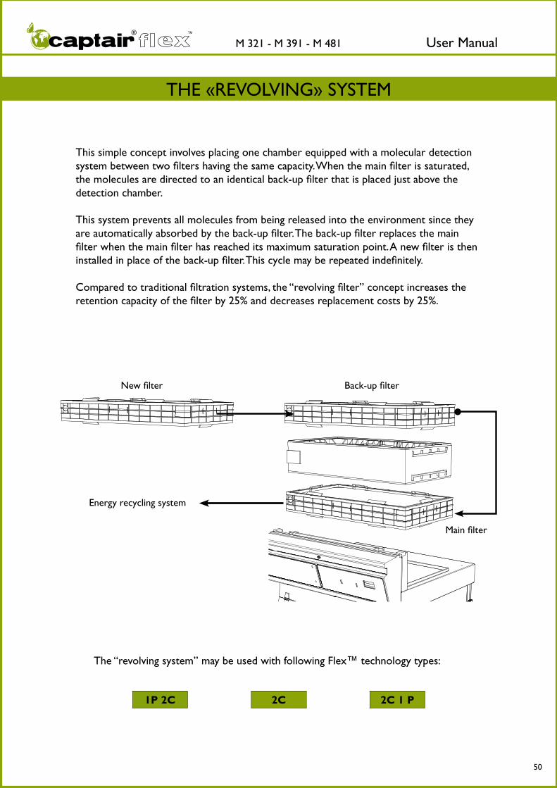
New filter
Main filter
Back-up filter
This simple concept involves placing one chamber equipped with a molecular detection system between two filters having the same capacity. When the main filter is saturated, the molecules are directed to an identical back-up filter that is placed just above the detection chamber.
This system prevents all molecules from being released into the environment since they are automatically absorbed by the back-up filter. The back-up filter replaces the main filter when the main filter has reached its maximum saturation point. A new filter is then installed in place of the back-up filter. This cycle may be repeated indefinitely.
Compared to traditional filtration systems, the “revolving filter” concept increases the retention capacity of the filter by 25% and decreases replacement costs by 25%.
The “revolving system” may be used with following Flex™ technology types:
2C 2C 1 P1P 2C
Energy recycling system
THE «REVOLVING» SYSTEM

User ManualM 321 - M 391 - M 481 TM
51
Replacement Hepa filter procedure
This procedure has been made for HEPA filters located on the low part of the filtration column and dedicated to the filtration of powders coming from the enclosure.
Following the Chronological order is imperative:
1. Switch on the Ductless Fume Hood
2. Fix the particles trapped by the Hepa filter by spraying the air lacquer (non inflammable) by crossed and repeated movements (to be done into the hood) on the lower face of the filter
3. Let dry for 5 minutes with the ventilation turned on
4. Switch off the ventilation, unplug the unit electric cable, the fan electric cable (or cables if several filtration columns) and the sample silicon pipe
5. Take off, cautionary, molecular filters (if any) and the fan box
6. Unwrap, cautionary, the new filter. Keep the plastic protection and the box to bag the used filter. The plastic protection must be placed on a flat surface close to the intervention spot.
7. Take off the used Hepa filter, lay it on the plastic protection, dirty face down.
8. Wash the filter housing with laboratory clothes impregnated with cleanser liquid. Wash the internal enclosure with the same way by fogging.
9. Wrap the used filter with used clothes and gloves. Close the plastic protection air tight with large scotch tape. If the plastic protection is damaged, do not hesitate to warp it again in an additional air tight bag.
10. Bag the sealed filter into the new filter’s box and close it with scotch tape. [Used filters must be disposed through an appropriate process, valorizing chemical wastes]
11. Install the new HEPA filter and reinstall the main molecular filter (if one), the column of filtration and the back-up filter (if one). Be sure that different layers are perfectly piled up with blades perfectly introduced into gutter. Note that it must form a perfect parallelepiped. Note that, in that process dedicated to the HEPA filter, molecular filter change is not considered
12. Reconnect pipes and electric cables, switch on the fume hood. Security control of the air face velocity according to the method described by the NFX 15-211 : 2009.
Before the maintenance:• The customer must send a list with all manipulated products in the enclosure and all the information useful to determine the toxicity
of those which will allow the technician to determine individual security equipments needed• No staff in the room and all manipulations need to be stopped• The laboratory must be mechanically or naturally aerated during the intervention
Individual security equipments needed:• overall + mobcap + bloomers• particulate mask• goggles• laboratory gloves

User ManualM 321 - M 391 - M 481 TM
52
Replacing the prefilter option (1 time per year)
1
3
5
2
4
6

User ManualM 321 - M 391 - M 481 TM
53
New prefilter installation
7
9
11
8
10
12

User ManualM 321 - M 391 - M 481 TM
54
CHECKING THE MECHANICAL PARTS
Hinges:Hinges must be properly attached and should not jam; they must allow the front panel of the hood to be instantly and easily lifted upward.
Acrylic parts:These parts must be clean; white streaks or spatters indicate rather heavy use of acid (hydrocholoric acid) or products handled at a high temperature. Ensuring the transpa-rency of the panels is a part of regular maintenance for the enclosure.
CLEANING THE ENCLOSURE
The enclosure must be cleaned on a regular basis.
This can be done using several different methods:
- Using soapy water then rinsing with clean water and drying with a smooth, non-abra-sive paper towel.
- Using a commercial pH neutralizer and drying with a smooth, non-abrasive paper towel.
- Using a commercial window cleaner.
Metal-plated parts:These parts should be inspected and must be free from any sign of corrosion.Verify that there is no stagnant water in the retention tray.Clean the retention tray if necessary.
CLEANING AND MAINTENANCE

User ManualM 321 - M 391 - M 481 TM
55
TECHNICAL SPECIFICATIONS
- Technical specifications- Spare parts list- Installing your hood

User ManualM 321 - M 391 - M 481 TM
56
TECHNICAL SPECIFICATIONS M 321
TECHNICAL SPECIFICATIONS
800 mm
678 mm
764 mm
312 mm
170 mm
295 mm
242 mm
160 mm
74 mm
543 mm
425 mm
866 mm
612 mm
1160 mm mini
1345 mm max
630 mm
* Total height according to filtration column type (mm)
Type 1P 1160 Type 2C 1256Type 1C 1160 Type 1P 2C 1345Type 1P 1C 1256 Type 2C 1P 1345Type 1C 1P 1256
Structure
Metallic parts Anti-corrosion metallic alloy protected by a thermo-hardened anti-acid polymer coating
Side and front panels 8 mm thick acrylic
Filtration module Polypropylene
SpecificationsNumber of columns 1Number of fans (IP44) 1Processed air flow 230 m3/h Air velocity at the openings in working position 0,4 to 0,6 m/s
Voltage / Frequency 90 - 264 V / 50 HzTotal power consumption including electricity for the lights 19 - 53 Watts
Amperage absorbed 1,6 amp.
Dimensions (mm)
Ref.External dimensions Internal dimensions - without work surface
Width Depth Height* Width Depth Height
M 321 800 6301160 mini1345 maxi
764 543 866
*According to filtration column type
User ManualM 321 - M 391 - M 481 TM
57
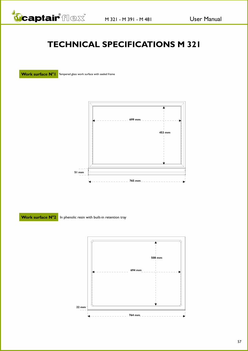
TECHNICAL SPECIFICATIONS M 321
Work surface N°2 In phenolic resin with built-in retention tray
Work surface N°1 Tempered glass work surface with seeled frame
453 mm
699 mm
51 mm
765 mm
508 mm
694 mm
764 mm
22 mm
User ManualM 321 - M 391 - M 481 TM
58
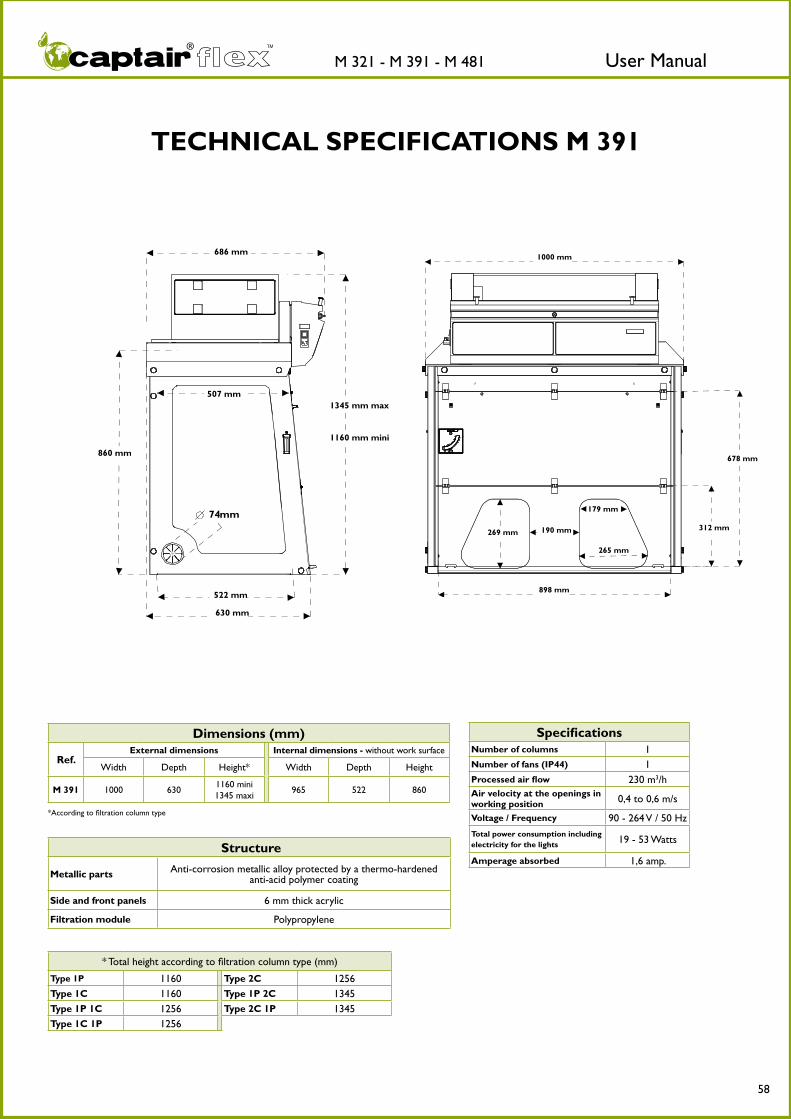
TECHNICAL SPECIFICATIONS M 391
* Total height according to filtration column type (mm)
Type 1P 1160 Type 2C 1256Type 1C 1160 Type 1P 2C 1345Type 1P 1C 1256 Type 2C 1P 1345Type 1C 1P 1256
1000 mm
678 mm
898 mm
312 mm
179 mm
190 mm269 mm
265 mm
860 mm
686 mm
507 mm
1160 mm mini
1345 mm max
522 mm
630 mm
74mm
Structure
Metallic parts Anti-corrosion metallic alloy protected by a thermo-hardened anti-acid polymer coating
Side and front panels 6 mm thick acrylic
Filtration module Polypropylene
Dimensions (mm)
Ref.External dimensions Internal dimensions - without work surface
Width Depth Height* Width Depth Height
M 391 1000 6301160 mini1345 maxi
965 522 860
*According to filtration column type
SpecificationsNumber of columns 1Number of fans (IP44) 1Processed air flow 230 m3/h Air velocity at the openings in working position 0,4 to 0,6 m/s
Voltage / Frequency 90 - 264 V / 50 HzTotal power consumption including electricity for the lights 19 - 53 Watts
Amperage absorbed 1,6 amp.

User ManualM 321 - M 391 - M 481 TM
59
TECHNICAL SPECIFICATIONS M 391
Work surface N°2 In phenolic resin with built-in retention tray
Work surface N°1 Tempered glass work surface with seeled frame
965 mm
453 mm
898 mm
60 mm
508 mm
965 mm
899 mm
832 mm
40 mm

User ManualM 321 - M 391 - M 481 TM
60
TECHNICAL SPECIFICATIONS M 481
1275 mm
678 mm
312 mm
163 mm
190 mm269 mm
258 mm
1176 mm
860 mm
686 mm
507 mm
1160 mm mini
1345 mm max
522 mm
630 mm
74mm
* Total height according to filtration column type (mm)
Type 1C 1160 Type 2C 1256Type 1P 1C 1256 Type 1P 2C 1345Type 1C 1P 1256 Type 2C 1P 1345
Structure
Metallic parts Anti-corrosion metallic alloy protected by a thermo-hardened anti-acid polymer coating
Side and front panels 6 mm thick acrylic
Filtration module Polypropylene
SpecificationsNumber of columns 1
Number of fans (IP44) 1
Processed air flow 230 m3/h
Air velocity at the openings in working position 0,4 to 0,6 m/s
Voltage / Frequency 90 - 264 V / 50 Hz
Total power consumption including electricity for the lights 19 - 71 Watts
Amperage absorbed 1,6 amp.
Dimensions (mm)
Ref.External dimensions Internal dimensions - without work surface
Width Depth Height* Width Depth Height
M 481 1275 6301160 mini1345 maxi
1240 522 860
*According to filtration column type

User ManualM 321 - M 391 - M 481 TM
61
TECHNICAL SPECIFICATIONS M 481
Work surface N°2 In phenolic resin with built-in retention tray
Work surface N°1 Tempered glass work surface with seeled frame
1176 mm
453 mm
1243 mm
60 mm
508 mm
1174 mm
1107 mm40 mm

User ManualM 321 - M 391 - M 481 TM
62
* : only for M 321 & M 391
TECHNICAL SPECIFICATIONS M 321 - M 391 - M 481
Modular filtration columnClass 2 - (NFX 15-211 : 2009 standard) Class 1 - (NFX 15-211 : 2009 standard)
Type 1CLiquid chemicals handlings
Type 2C Liquid chemicals handlings
Type 1P 1CLiquid chemicals and powders handlings
Type 1P 2CLiquid chemicals and powders handlings
Type 1C 1PLiquid chemicals and powders handlings in clean room
Type 2C 1PLiquid chemicals and powders handlings in clean room
Molecular filter H14 HEPA filter
Equipments
Compliance to standardsTypes of filters available
AFNOR NF X 15-211:2009 - France ANSI/ASHRAE 110-1995 - USA BS 7258 - England CSA Z316.5 - Canada
CE Marking NF P.92.507 (Acrylic part) EN 1822 : 1998 (H14 HEPA filter )
GF4 AS For organic vapours
GF4 BE + For organic vapours + acid vapours
GF4 F For formaldehyde vapours
GF4 K For ammonia vapours
GF4 HP H14 HEPA Filter for powders
Modular filtration column
Type 1P *Powders handlings
Standard Equipment
Air flow meter Permanent air face velocity monitoring system
Flow monitor Permanent ventilation control device according to EN 14175-2:2003 standard
Internal lighting Compact tubular fluorescent lighting - 18 Watts - 500 Lux - IP 67
Sampling port For filter saturation detection (N/A if Molecode S installed)
Programmable timer Timer - 60 hours setting by default ac-cording to NFX 15 211: 2009 standard
Energy ports For the passage of cables
Chemical Listing List of approved chemicals
Options
Molecode S* Automatic alarm to detect filter saturation by solvents according to NF X 15 211 : 2009 standard (*compulsory for class 1 configuration)
Work surface N°1 Tempered glass work surface with seeled frame
Work surface N°2 In phenolic resin with built-in retention tray
Mobicap Rolling cart made of anti-corrosion metallic alloy (only for M 321 & M 391)
Benchcap Fixed work bench made of anti-corrosion metallic alloy
Shelf Adjustable slinding shelf for Mobicap and Benchcap
Transparent back panel Acrylic
Access door on rear panel For maintenance interventions
Particular Pre-filter
40 % filtration efficiency for particles > 0,3 µm

User ManualM 321 - M 391 - M 481 TM
63
M 321 - M 391 - M 481
NamePart numbers
M 321 M 391 M 481 Ventilation card PIDEL8502
Switch mode power supply PIDEL8509Line conditioner PIDEL8513
5x20 4A fuse PIDEL085CPU card PIDEL8523
175 mm fan PIDVE8500Nylon screw M8 x 20 PIDB087Nylon screw M8 x 25 PIDB086
White polypropylene hinge PIDMS301White knurled nut PA 6.6 PIDMS302
Acrylic panel with cut-out for anemometer B PIDVI3736-1 PIDVI3748Plain acrylic panel PIDVI3737-1 PIDVI3748
Lower door PIDVI3750 PIDVI3745 PIDVI3757Upper door PIDVI3504 PIDVI3509 PIDVI3756
Visor PIDVI3506 PIDVI3511 PIDVI3755Prefilter I1015000001
SPARE PARTS LIST

User ManualM 321 - M 391 - M 481 TM
64
WARNING
User ManualM 321 - M 391 - M 481 TM
65
1 m.
min
0,3
m.
1 m.
1,4 m.
3 m.min 2,7 m
1,4 m.
!
!
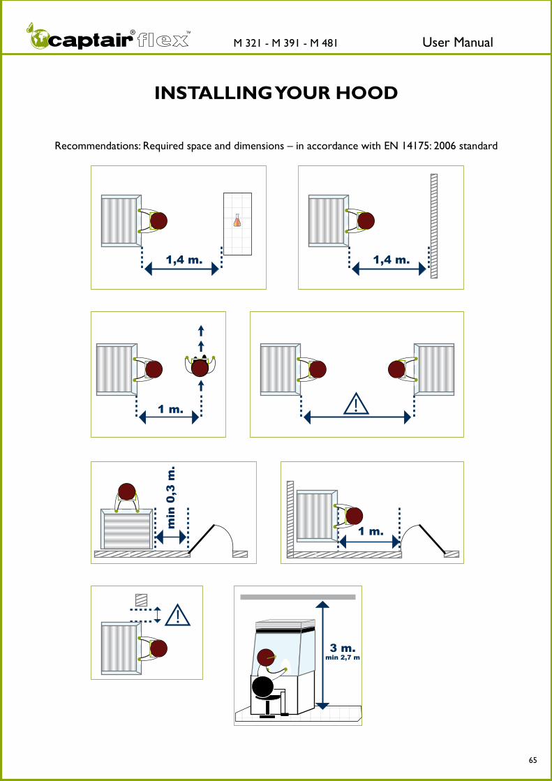
Recommendations: Required space and dimensions – in accordance with EN 14175: 2006 standard
INSTALLING YOUR HOOD

User ManualM 321 - M 391 - M 481 TM
66
WARNING
Feel free to contact our company at any time with any questions related to the set-up,
maintenance, or use of this device. Our team is at your disposal, providing you with clear and
detailed responses in a timely manner.
The E.S.P.® program (Erlab Safety Program) was established to guarantee your safety. We remind you of the need to verify the safety parameters before using the device for the first time and in the event of a new application.
Substances that are carcinogenic, mutagenic, or toxic for reproduction (CMRs) may be handled underneath a fume hood according to the French Labor Code. However, the nature of these chemicals requires special attention from their users.
The device is not designed to be used in an explosive environment.The filters delivered with this device must be removed from their packaging, positioned correctly, and must be suitable for the type of chemicals being handled in order to guarantee user safety.
Erlab® recommends testing for filter saturation on a regular basis.
Although the Timer™ alarm can be deactivated, Erlab® recommends keeping the alarm activated. This alarm is triggered after every sixty hours of operation.
Erlab® recommends regularly monitoring the air face velocity according to the values set forth by AFNOR NF X 15-211: 2009 standard.
The quantities of the chemicals handled in the enclosure should not be greater than those listed in the guide of approved chemicals (the Chemical Listing).
AFNOR NF X 15-211: 2009 standard specifies that only those chemicals with a TLV (Threshold Limit Value) should be handled in the enclosure. These chemicals must also be included in the exhaustive list of authorized substances provided by erlab®. In accordance with NF X 15-211: 2009 standard, it is only pos-sible to carry out operations that can be immediately stopped in a class 2 enclosure. The fume hood’s filter must also be replaced as soon as the presence of a chemical is detected downstream from the filter.
New filters must be stored in their packaging, laid flat, in a dry place.
Erlab® recommends keeping a log specific to this device that includes the chemicals handled, the frequency with which these chemicals are handled, as well as any operations related to device maintenance.

erlab Asia SDN BHD Malaysia
erlab inc. - USA
erlab D.F.S S.A.S Head Office - FRANCE
erlab S.L SPAIN
Kunshan erlab D.F.S. - co Ltd. CHINA
EUROPE
FRANCE : erlab D.F.S. S.A.S. Parc d’Affaires des Portes BP 403 27104 Val de Reuil Cedex Tel. : +33 (0)2 32 09 55 80 Fax. : +33 (0)2 32 09 55 90 E-Mail : [email protected]
U.K. : erlab D.F.S. S.A.S. UK and Ireland representation office Home Farm Buildings / Home Farm Netherhampton - Salisbury - SP2 8PJ Tel. : +44 (0)1722 341 940 Fax. : +44 (0)1722 341 950 E-Mail : [email protected]
GERMANY : erlab D.F.S. S.A.S. Vertretungsbüro Deutschland Siegburger Straße 215 50679 Köln Tel. : (0)800 330 47 31 Fax : (0)800 330 47 32 E-Mail : [email protected]
ITALY : erlab D.F.S. S.A.S. Ufficio di rappresentanza in Italia Via Leone XIII, 10 – 20145 Milano Tel. : +39 (0)2 89 00 771 Fax. : +39 (0)2 72 097 812 E-Mail : [email protected]
SPAIN : erlab S.L. Pol. Ind. Sur Passaje Newton 3A 08754 El Papiol-Barcelona Tel. : +34 93 673 24 74 Fax. : +34 93 673 24 76 E-Mail : [email protected]
NORTH AMERICA
U.S.A. : erlab inc. 388 Newburyport Turnpike Rowley, MA 01969 Tel : +1 (978) 948-2216 Fax : +1 (978) 948-3354 E-mail : [email protected]
ASIA
CHINA : Kunshan erlab D.F.S. co Ltd. 100 Liu Shi Jing, road Kunshan Development Zone Jiangsu Province Penglang - P.R. China 215333 Tel. : +86 (0) 512 5781 4085 Fax. : +86 (0) 512 5781 4082 E-mail : [email protected] MALAYSIA : erlab asia sdn bhd 25 Jalan Firma - /1 Kawasan Perindustrian Tebrau - 81 100 Johor Bahru, Johor State Tel. : +60 (0)7 3 555 724 Fax. : +60 (0)7 3 552 810 E-Mail : [email protected]
w w w . e r l a b . c o m
International [email protected]
World Leader
Top Related