


Languages
Pages
Legal

CAPPInternational Research Project on the Effects of Chemical
Ageing of Polymers on Performance Properties
FLEXIBLE PIPES -
PERMEATION OF METHANE,CARBON DIOXIDE AND WATER
THROUGH TEFZEL ETFE -
Experiments 1996
Prepared for:
Prepared by:
Document no:
Document date:
CAPP Joint Industry Project
Per Arne Wang, Norsk Hydro
97Q-BG3.DOC
CAPP/N.3
18 April 1997
9063 Bee Caves Road, AustinTexas 78733-6201, U.S.A.Tel: 1-512-263-2101
Tamworth Road, HertfordSG13 7DG, England
_ Research CentrePorsgrunnREPORT
Classification: Internal
Title:
Flexible pipes.
Permeation of methane, carbon dioxide and water through Tefzel ETFE.
Experiments 1996.
Author(s):
Per Arne Wang
To:
T. Andersen, HRE
Copy:
Dr. Bob Campion, MERL
M. Tystad, T&U VK
B. Moursund, HRE
C. Hansteen, HRE
Reg./circ.
Front page:
K. Harg, HRE
R. Steen Hansen, HRE
F. Ellingsen, HRE
Date: 1997-04-18
File no.: 972.61
ProJ.no.: R23965.200
Arch. per.: Permanent
Doc.no.:
Pages/App.:
Ref.:
97Q_BG3.DOC
6/4
PAW:(VN)
Keywords:
PERMEABILITET VANN
METAN ETFE
KARBONDIOKSYD FLEKSIBLE ROR
Approved project [Approved project
leader: ] respo_
Guidelines for approval are descdbed in the Research Centre Quality Handbook (HRE-I-1)
Summary/Concluslon:
The permeation of a mixture of CH 4 and CO 2 (97% CH 4 and 3% CO 2) saturated with water
vapour through Tefzel has been studied at 95°C and 25 and 50 bars. Tefzel is the Du Pont
trademark of an ETFE (ethylenetetrafluorethylene) which is a copolymer of ethylene and
tetrafluorethylene. This material might be used as inner plastic lining of flexible pipes.
The permeability coefficients (P in cm2/sobar) for CH 4, CO 2 and water at the various
temperatures are found to be:
Permeability, (cm2/s.bar)
CH4 CO2 H203.65E-08 2.09E-07 1.62E-06
For methane and carbon dioxide, the permeability of Tefzel is higher than the deplasticized
PVDF (Polyvinylidenefluoride), but lower than the plasticized PVDF. For water, the situation
seems to be the other way round; Tefzel has a lower permeability than deplasticized PVDF.
Whether the permeability tests on Tefzel at higher temperatures and pressures will be pursued
or not, will be considered by the steering committee of the CAPP project in May.
Research CentreInternal
Page 2 of 6
. Introduction.
This document describes the permeation test of Tefzel ETFE (Ethylene Tetra Fluor
Ethylene) performed in 1996.
u Experimental and testing parameters.
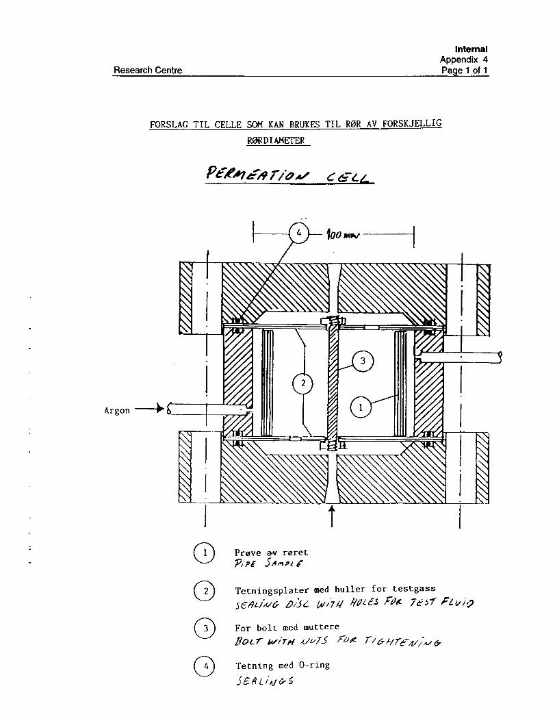
The experiments are performed with a new pressure cell. One advantage of this cell
is the possibility of testing on various pipe dimensions, up to 90 mm OD. In principle
though, the same experimental set-up as described in the previous report was used in
these measurements (/1/,/7/). A drawing of this new cell can be found in App. 4.
The permeation is measured from a pressurised test gas inside a sealed pipe section.
The sample pressure is balanced with argon on the outside. The argon gas flushes
the outside and brings the permeated gases to a gas chromatograph and a moisture
detector for analysis. The saturation of the gas mixtures with water was performed at
the actual temperature.
The test series that were planned to be performed on Tefzel are shown in Table 1.
Due to system- and component failures, fewer test runs are performed in 1996 than
planned. Thus, there are no results ready yet for other pressures and temperaturesthan described in the table.
The CAPP steering committee will decide (May 1997) whether the tests on Tefzel
will be pursued according to plan or not.
Table 1. Overview of the planned testing parameters. One can see that only
the 25 and 50 bar at 95cC testing is finished. The gas mixture is
fluid B according to the CAPP nomenclature.
Gas mixture
(All saturated with water)
97% CH4/3% CO z
97% CH4/3% CO 2
97% CH4/3% CO z
97% CH4/3% CO z
Temperature
(oc)70
Pressure
25, 50, 75, 100, 120
95 25,50
95 75,100,120
120 25,50,75,100,120
Status
Pend!ng
Finished
Pending
Pending
The permeation rates and permeability coefficient were determined as described in
the previous reports/1/,/71. The permeability coefficients were calculated by using
equation 1, which applies to a cylinder.
P = q In(K) (Equation 1)t 2IrL(pl-p2 )
q/t = permeation rate, p_ and P2 are the high and low (inside and outside) partial
pressures. The dimension of the permeability coefficient is cmZ/sobar.
Research CentreInternal
Page 3 of 6
Results.
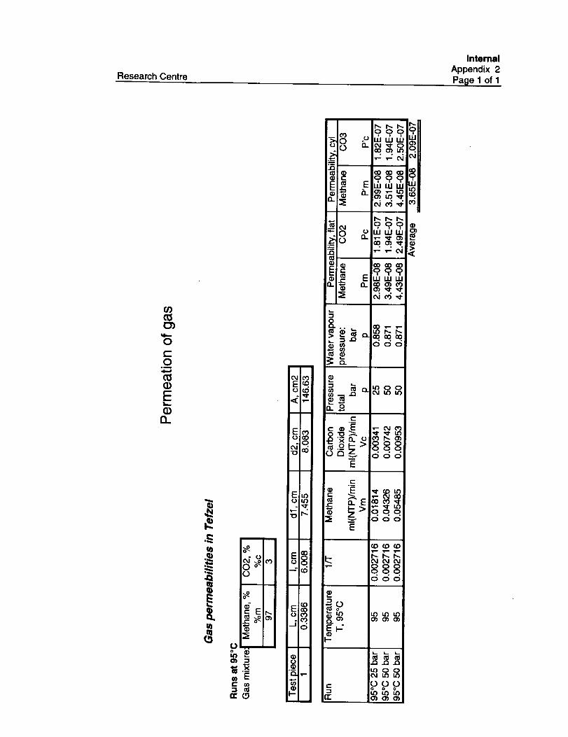
Methane and carbon dioxide.
The amount of each gas permeated through the sample and associated permeability
coefficients for methane and carbon dioxide at each pressure are given in App. 2.
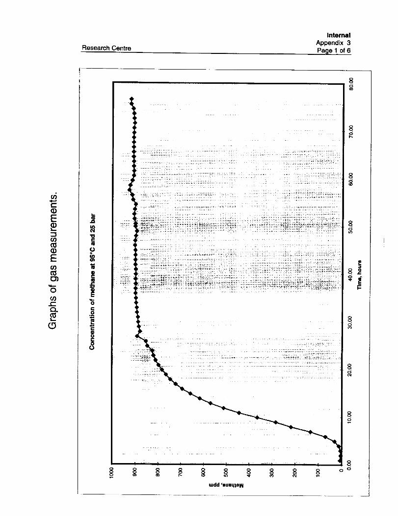
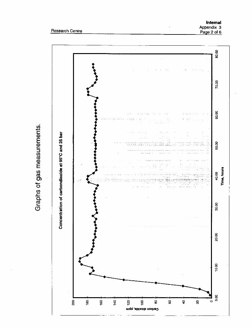
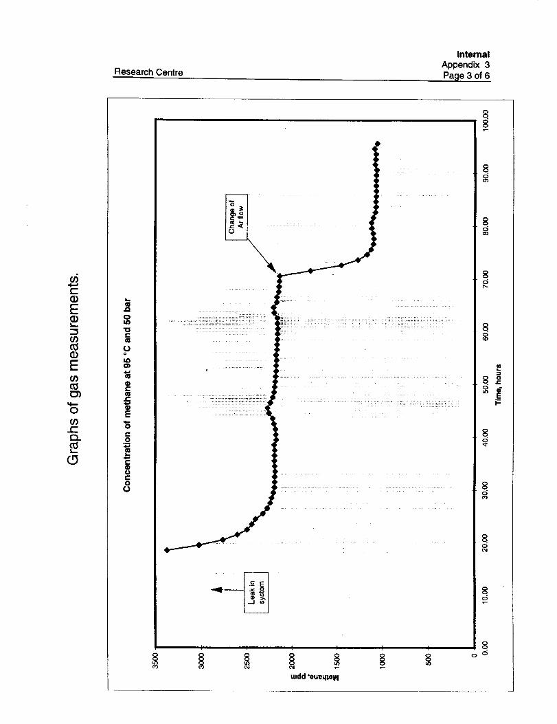
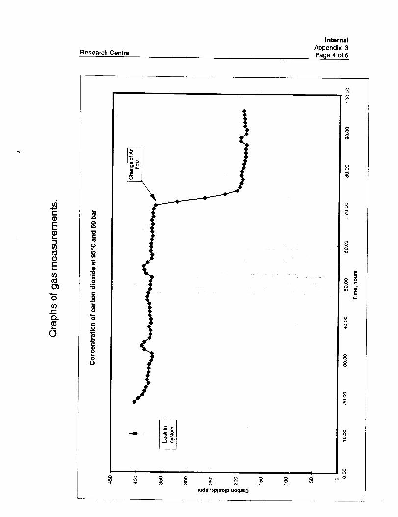
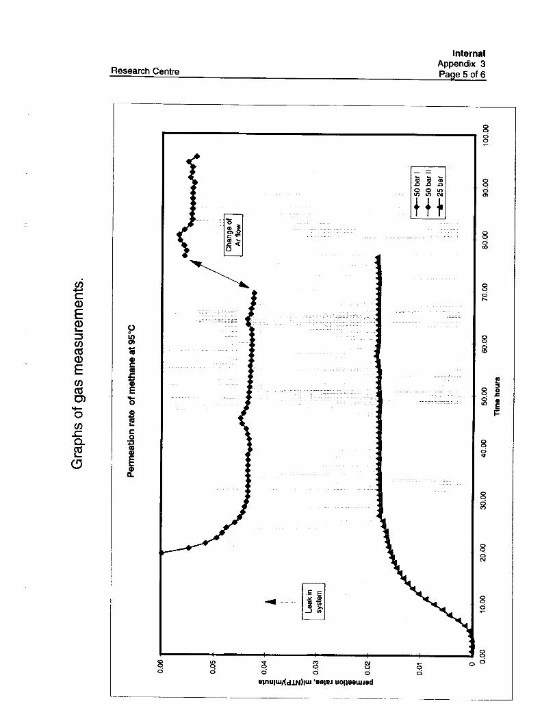
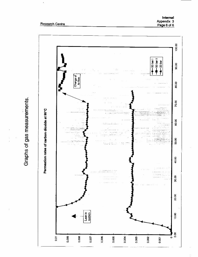
A graphical presentation of permeation rates and concentrations as a function of time
can be found in App. 3. Table 2 below shows a summary of permeability data for the
gases.
On the 50 bar run, the flow of argon was increased from 20 to 50 ml/min in order to
improve the stability of the analysis. The effect of this was that the concentrations
increased, and thereby a higher permeability rate was found. However, the increment is
insignificant in the scales used for evaluation. Details can be seen on the concentration
and permeation charts in App. 3. No explanation could be found yet on this effect.
Table 2. Summary table for methane and carbon dioxide.
Run
95°C 25 bar95°C 50 bar I95°C 50 bar II
Average
Permeability
(cm2/s-bar)Methane C022.99E-08 1.82E-073.51E-08 1.94E-074.45E-08 2.50E-07
3.65E-08 2.09E-07
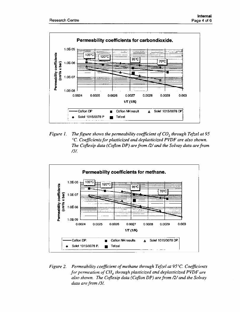
For comparative purposes, the average Tefzel permeability is plotted together with
the permeabilities of other materials previously tested (Figures 1-2). One can see that
for this particular temperature and pressures, the permeability of carbon dioxide and
methane through Tefzel ETFE is lower than through Solef and Coflon PVDF.
Research CentreInternal
Page 4 of 6
m"E.2
E.=
Permeability coefficients for carbondioxide.
1.0E-05
1.0E-06 =L 9 °01 !,o-- _L _ .... -- i
.J
0.0026 0.0027 0.0028 0.0029 0.003
1.0E-07
1.0E-08
0.0024 0.0025
1/T (l/K)
--Coflon DP • CoflonNHresult A Solef 1015/0078 DP• Solef 1015/0078 P • Tefzel
Figure 1. The figure shows the permeability coefficient of CO 2 through TefzeI at 95
cC. Coefficients for plasticized and deplasticized PVDF are also shown.
The Coflexip data (Coflon DP) are from/2�and the SoIvay data are from
/3/.
Permeability coefficients for methane.
1.0E-06m
.2
i E 1.0E-08
&
n
i'95°C I -_' t
t'°°cl---
++__
1.0E-09
0.0024 0.0025 0.0026 0.0027 0.0028 0.0329 0.003
1/T (1/10
--Coflon DP. • Coflon NH results ,_, Solef 1015/0078 DP.
• Soef 1015/0078 P. • Tefzel
Figure 2. Permeability coefficient of methane through Tefzel at 95 cC. Coefficients
for permeation of CH 4 through plasticized and deplasticized PVDF are
also shown. The Coflexip data (Coflon DP) are from/2�and the Solvay
data are from/3/.
Research CentreInternal
Page 5 of 6
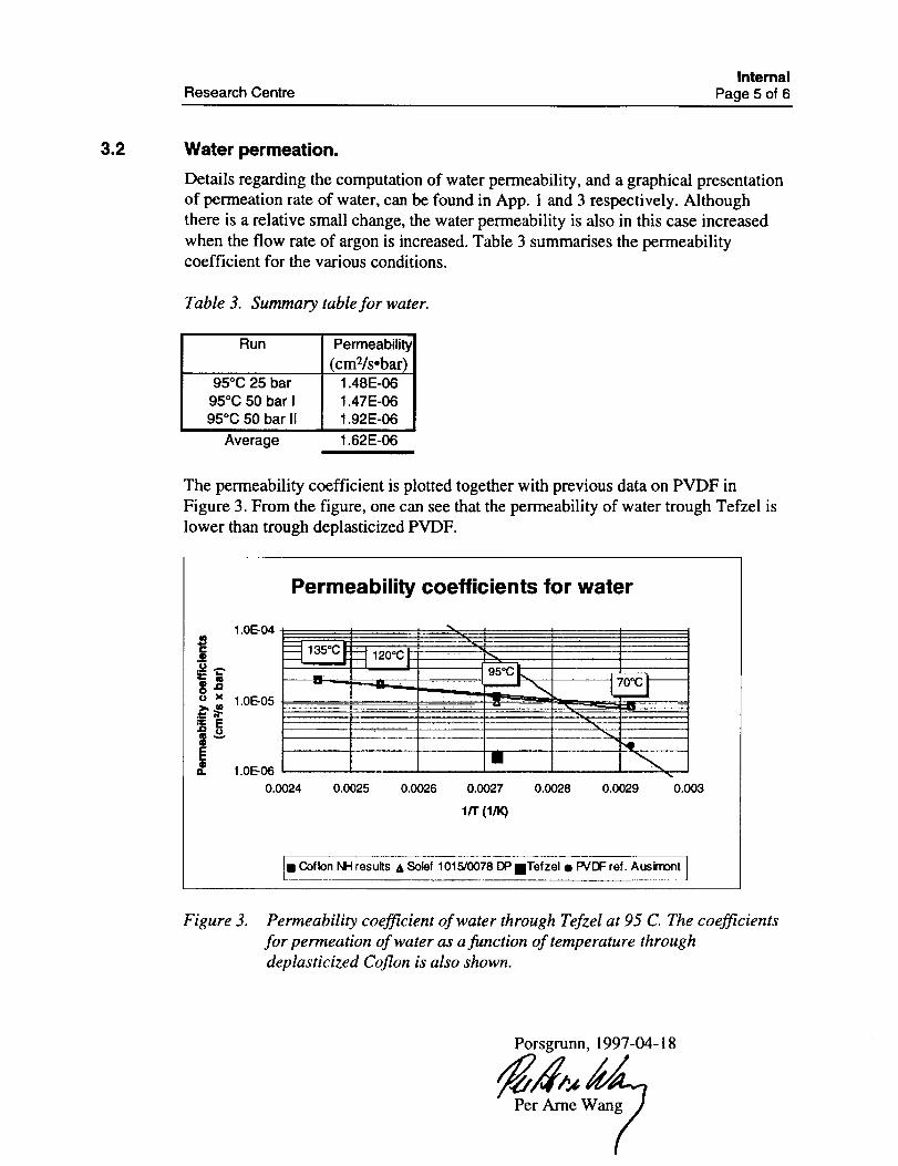
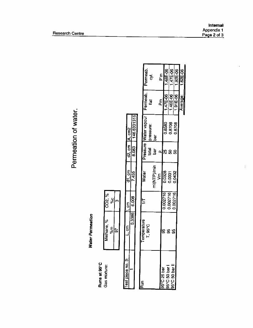
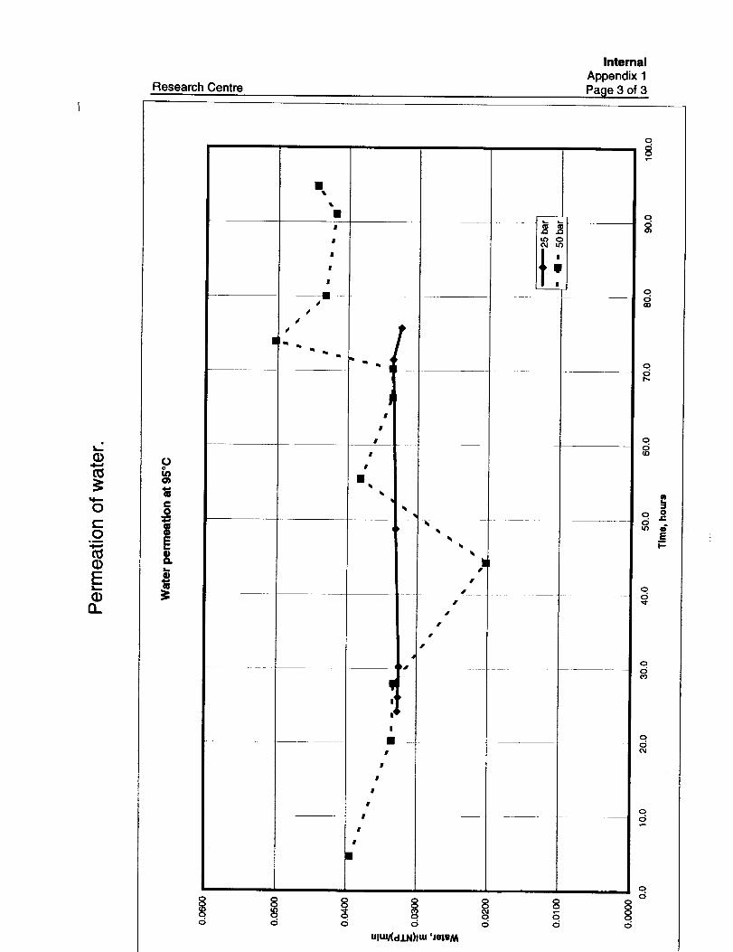
3.2 Water permeation.
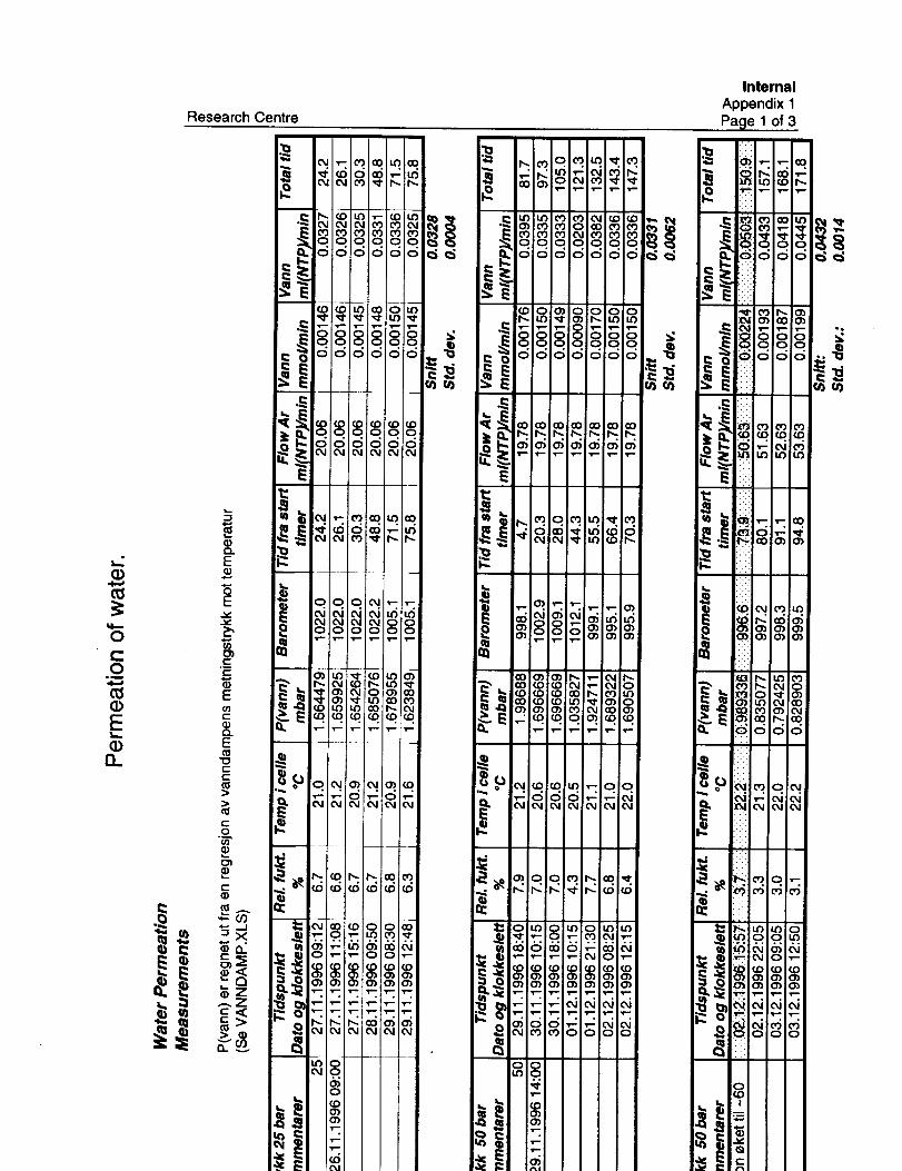
Details regarding the computation of water permeability, and a graphical presentation
of permeation rate of water, can be found in App. 1 and 3 respectively. Although
there is a relative small change, the water permeability is also in this case increased
when the flow rate of argon is increased. Table 3 summarises the permeabilitycoefficient for the various conditions.
Table 3. Summary table for water.
Run Permeability
(cmVs.bar)95°C 25 bar 1.48E-06
95°C 50 bar I 1.47E-0695°C 50 bar II 1.92E-06
Average 1.62E-06
The permeability coefficient is plotted together with previous data on PVDF in
Figure 3. From the figure, one can see that the permeability of water trough Tefzel is
lower than trough deplasticized PVDF.
Permeability coefficients for water
1.0E-04 ii r ' _1: _:' III
iiiiiii ii n L I1.0E-06
0.0024 0.0025 0.0026 0.0027 0.0028 0.0029 0.003
1/1" (l/K)
= Coflon NH results & Solef 1015/0078 DP mTefzel • PVDF ref. Ausimont
Figure 3. Permeability coefficient of water through Tefzel at 95 C. The coefficients
for permeation of water as a function of temperature through
deplasticized Coflon is also shown.
Porsgrunn, 1997-04-18
Per Arne Wa
Research CentreInternal
Page 6 of 6
w References
Ill J. I. Skar, "Permeabilty of methane and carbon dioxide through plasticized
polyamide (PA 11) and polyvinylidenefluoride (PVDF). Norsk Hydro Doc. No.
94R_DS6, 1994-09-02. (CAPP/N.1)
/2/ B. Radenac, "COFLON - A material for inner lining of Coflexip flexible pipe".
Coflexip report no. 93.05.06, September 1993.
/3/ "Solef PVDF for offshore applications". Presentation in Brussel by Solvay,
January 31. 1996.
/4/ Design Guide, "HALAR ECTFE" Ausimont USA. Inc. 1992.
/5/ G.J. Morgan and B. Campion, CAPP/M.4 Rev. B.
/6/ Giddings, Myers, McLaren, Keller, Science 162, 67 - 73 (October 1968).
/7/ Skar, Jan Ivar; Hansteen, Christoffer : "Flexible Pipes. Permeation of methane,
carbon dioxide and water trough polyvinylidenfluoride"; Report HRE;
96Q_DC8.DOC; File 972.61.
(1)
O¢.-O
E
0..
Research Centre
¢.-
InternalAppendix 1
.Parle 1 of 3
._ m u_io01o0'o_l_o_o _ _'o_loo'u_m m mlo ooloo_ _ o _i,- _" Z
_ __'_'__'__ i
o O_OlO OlO o _ '_ "="'=" _o olo o
l_iolmlo_oloo _"__ jr-.,o'>i"-_i'_l'iO) r,-Im LO :Od 0_I00 O_• " '_" '_'-' '_'- 'r-. '_'- .L'_ .,-- | '_.'....r-•S /o o o o ,S=__olo1_olo_ddddddo "_ _ _°1°_
_ _°
"_ II "°r--I_l_ _1 r',.._ _ © © co
'i'11
•
e el_lo=1==l _ NN_;¢;°'1"1-°1°° a _°1°°
-_ (OI(DIC_I _-I_ OI _-_ i_ 1_104¢ _. _ (DlCZ)ICO I_ICq u31 _ _1:¢_ O1_" O
(DI_OlU3 "¢10_ OI _ _10_ u_lo4<:7) <3)10)1o') C_I00 O_1 =- .=alOO o310_
_1_1_1_1 _1_o=1_
iiiiii ii°
Research Centre
InternalAppendix 1Page 2 of 3
E¢_
Q.
C
i
o_OI
L)
co EC ¢n
n-L_
mm ==1=U3
O3
O3O3
OJ(D
<_,--m
E_O.C>
o_06"O
Eu')¢3u_
co
.._=m
co00o3o3
o
EO
_5
_6dr-
Q
0)
_,i_= -i .i •
O
• ° .
_ oooCL.Q
e-+_
+dddE
- oo_o• • 0
000
i--
a)c_
o¢-o
(g(DE(1)
Q_
Research Centre
InternalAppendix 1Page 3 of 3
oo
&L_
8l3=
O
I
I
I
|
I
l
|1,.
m
r_ _ ¢ P
I
j,
4,
i I
lI
¢,
i
11
I
f
B
O
8
d
/
f
J
o c_
UlW/(dlN)ltU 'JelWM
U) OO4 u3
|
|
8O
O O
q8
qOO)
=oo.
O
qO03

Ill
Research Centre
InternalAppendix 2Page 1 of 1
n
Q.
•0
o
_,__m Ec _
P_ b,. b..
8 °9°co IjJ IJJ W_-_o.0 0oo>Ln
J_ ® O0 O0 O0
®c 099
o_ LO '¢1-
_.ZZ_8 999g_o _ ,,,,,,w
00 o_ ,,¢
_® ,-: ,= _i >=
N _,i ./
-,!
,odd
e
_N
ddd
e-
_r S o
_ _. ¢5<5 "
¢D ¢D _D
• IP- 888• • ,
ooo
,¢
_oo,'o
to I.q u')
Research Centre
InternalAppendix 3Parle 1 of 6
cO¢-
L_
i
oo
IE"6c.o
c-
c-oo
L'."
4
• I
,,,dd 'oueqlow
8doO
8.O
8d¢D
u_
.=
J¢
8c_O3
Research Centre
Internal
Appendix 3
Page 2 of 6
t-(!)E(D
03
q_
cOC_
O
03c-"C].
(.9
It)OI
"Oe-
PIt)
O
e-
t-O
O
P
8o_o
8df..
8(5(D
8o
Research Centre
InternalAppendix 3Page 3 of 6
c-(1)E
Or)
(1)
03.CQ.
I,..
C_
Im0l
.¢tO
'10CW
IJo
0
e-.9
c0oC0
8if)
\
\\
i
I I i I
uudd 'oueq3,ow
8
8¢5O3
8OCD
P8 _
J_
8.O
8
O
O
O O
Op_
8o
00
Research Centre
InternalAppendix 3Page 4 of 6
c-
Et=,.
u)
E
0")Nk,,-
0
¢-Q.
L_
.ao
'u=..
o
X.o'U
=-0
.at_
(J
"6i-0
.m
r-
r-0
,,_ __m
todd '0plx01p u0_u3
I I I
o 8 o
8d0
8.0
8.0
8.0
80
8o
g0
8.0 0
80
0
Research Centre
InternalAppendix 3Page 5 of 6
u_(-(1)E
0¢)
E03
O)
O03¢-£).
I,.,
oo
iO
Oo_
¢_
O.
O O
/
b
! I I
• Od o d
olnulm/(d.LN)lm 'soleJ u01|uou_Jod
I i
O
O
8
8dO1
8dcO
8Ol%
8OCD
.=8
• J-
l-
8O'd"
8O O
8
Research Centre
InternalAppendix 3Page 6 of 6
u5
O)t.l,.,,
O(/)(-(D.O3
(.D
o d d d d d d d d d

Research Centre
Internal
Appendix 4
Parle 1 of 1
FORSLAG TIL CELLE SOM KAN BRUKES TIL ROR AV FORSKJELLIG
R_R D IAP_=R
Pt"l_l,/ =:/_ 1"/'@# ( _-t.. L
Argon
I
\\ I I'" I I
%%
\\ I I
1(1)
2}x..j
{ 3iv
I 41
Prove a_ roret
Tetningsplater med huller for testgass
For bolt med muttere
Tetning med O-ring