


Languages
Pages
Legal


6/19/2012
1
CALCULATING SECTION LOSS
IN STEEL MEMBERS
Bureau of Bridges & Structures
Introduction 2
o Class Instructor: Mike Cima, PE, SE
o Background:
o Over 22 years of bridge structure experience
o 17+ with IDOT BB&S, 4+ with Hampton Lenzini & Renwick
Engineering (Elgin/Springfield/Romeoville)
o Past experience includes bridge inspection, design and
policy development
o Inspection experience includes most types of structures
o Licensed PE and SE in Illinois

6/19/2012
2
Introduction 3
o If you have Questions or Comments during the
course of the webinar do the following:
o Look on your computer screen for a “red box with an
arrow in it”, click on this to open the Question Function.
o Type in and enter your questions to send to us.
o We fill pause periodically during the webinar to
answer questions verbally.
Webinar Agenda
o Purpose
o Background
o Common Steel Members
o Critical Areas
o Measuring Equipment
o Taking Measurements
o Documentation
o Calculating Section Loss
o Examples
4

6/19/2012
3
Purpose of Course
The purpose of this webinar is to refresh the skills of
personnel conducting bridge field inspections in the
process of documentation and calculation of section
loss in steel structural members.
The resultant section loss information, used in
conjunction with IDOT’s Structure Information and
Procedure (SIP) Manual criteria for Items # 59 & 60,
Steel Superstructure or Substructure, will allow the
inspector to determine the correct element condition
rating.
5
Background
o Why is Section Loss measurement important?
o When a structural member loses area from its design section the engineering properties of the member are changed.
o This can have a negative effect on the following structural capacities of the member:
o Flexure (moment of inertia & section modulus)
o Shear (cross sectional area)
o Tension & Compression (cross sectional area)
o Bearing (cross sectional area)
6

6/19/2012
4
Background
Why is Section Loss
measurement important?
o If the degree of section
loss becomes too great
the member affected
could become structurally
unstable.
o This could result in the
partial or complete
failure of the structure.
7
Common Steel Members
o Many types of steel
members are used in
bridge structures.
o A few of the most
commonly used shapes
are shown on the
following slides.
8

6/19/2012
5
Common Steel Members
o Common Sections: o Plate Girder (welded or
built up member)
o Wide Flange
o Other “I” Sections
o Member may also include flange cover plates.
o Typically used as longitudinal girders in bridges and in truss floor systems.
9
Common Steel Members
o Channels: (often used
singularly or in pairs).
o Angles: (often used
singly or in groups of
two or four).
o These members are
common in truss bridges
and bracing systems.
10

6/19/2012
6
Critical Areas - Defined
o Critical Areas, as defined in determining condition
ratings using the IDOT SIP Manual, apply to areas on
structural members where if damage occurred, it
could significantly affect the capacity of the member.
o These areas can vary with the type of member, where
the member is used and the location of the damage
on the member within the structural system.
o Critical areas on some of the most common steel
member types are covered in the following slides.
11
Critical Areas – Flexural Members
o Members in flexure
typically develop the
highest bending stress at
the flanges, making this a
critical area.
o Section Loss in the flange
reduces the members
flexural capacity.
12

6/19/2012
7
Critical Areas – Flexural Members 13
High flexural stress in simple span structural members is
typically found in the location shown below.
Critical Areas – Flexural Members 14
High flexural stress’s in continuous span structural members
are typically found in the locations shown below. (Note: These
locations vary depending on the span ratios.)

6/19/2012
8
Critical Areas - Shear
o Members in shear carry stress
primarily parallel to the axis
of the applied load.
o In I-shaped flexural members
the bulk of the shear stress is
typically carried by the web
making this a critical area.
o Section loss in this area
decreases the members shear
capacity.
15
Critical Areas - Shear 16
High shear stress in structural members is typically found in the
locations shown below near the bearing points. (Note: These
locations vary depending on the span ratios.)

6/19/2012
9
Critical Areas – Tension & Compression
o Tension & Compression members come in many types: W, angle, channel, pipes, rods, bars, etc.
o The tens./comp. stress is often roughly evenly distributed in the member through most of its length.
o The critical area on these members is generally any point on the member.
17
Critical Areas – Tension & Compression 18
High tension or compressive stresses in structural members
are typically found in the locations shown below.

6/19/2012
10
Critical Areas - Bearing
o Bearing occurs where one
structure member rests on
and transfers load to
another through contact, such
as a superstructure girder
resting on a substructure cap.
o Bearing stress is highest in
the steel girder immediately
above and adjacent to the
bearing location.
o The critical area in this case
is the beam web.
19
Measuring Equipment
Ultrasound Thickness (UT) Gauge:
o Used to measure homogenous metal
thickness remaining.
o Often best choice for determining steel
thickness remaining.
o Need a relatively clean and smooth
surface to measure from.
20

6/19/2012
11
Taking Measurements
What do you need to consider when taking Section Loss measurements?
o Where is the critical location.
o What line to measure along.
o How many measurements to take.
21
Taking Measurements Determine Critical Location
o Review the damaged sections of the steel member being inspected.
o Determine the location(s) with the greatest section loss.
o If you are unsure where the critical location is, take measurements at multiple damage points with heavy section loss.
o A hole in a member does not mean the member has 100% section loss.
22

6/19/2012
12
Taking Measurements Determine Line of Measurement
o The line of measurement to determine the max section loss is often at right angles to the longitudinal axis of the member.
o The line passes through the location of greatest overall section loss in that area as shown.
o In some cases however; the line of maximum section loss may occur at an angle other than right angles to the member.
23
Taking Measurements Determine How Many Measurements
24
o The number of measurements required depends on the
length of the “line of measurement” on the damaged
member.
o A minimum of three (3) measurements is generally desirable
or one measurement every 2-3 inches.
o Take the measurements at equal spacing along the line of
measurement.
o The inspector must use good judgment in determining the
number of measurements to take.

6/19/2012
13
Documentation
What Information is needed to Document the Section Loss?
o Sketch of member with measurement readings.
o Documenting the sketch and inspection findings.
o Photo(s) of damage.
25
Documentation Damage Sketch - Example
Location Measurement
A 0.24''
B 0.58''
C 0.66''
D 0.67''
E 0.67''
F 0.66''
26

6/19/2012
14
Documentation Damage Sketch - Documentation
27
o Place identification data on the sketch:
o Name of inspector
o Date of inspection
o Structure Number and bridge location
o Damage location information
o Provide a sketch of the damaged member with details:
o Sketch out an adequate portion of the damaged member to clearly communicate where the damage is located.
o Detail each type of distress in a distinctive maner and provide a key to distinguish the types if necessary.
o Place linear and area dimensions on the distress as appropriate.
Documentation Damage Sketch - Documentation
28
o Place a dimension to the damaged location from an
easily recognized known point of reference on the
structure.
o Provide a cross section sketch(s) through the most
heavily damaged locations.
o Show the “Line of Measurement”, angle of
measurement, measurement point locations and
measurement reading at each measurement point.

6/19/2012
15
Documentation Damage Photo(s)
o Take clear photos of the damaged area.
o Use an object for scale reference if necessary.
o Keep a log to identify the location and direction each picture was taken from.
o Use adequate distance from location to allow for overall perspective.
29
Calculating Section Loss
o For I-shaped flexural members, these areas include:
o Flexure locations – the individual flanges
o Shear locations – the web
o Bearing locations – the web above the bearing
o Tension & Compression Members – full member area
30

6/19/2012
16
Calculating Section Loss
o To calculate the percent Section Loss (SL) for a critical area
do the following:
o Calculate the original cross sectional area of the element
according to its “as built dimensions” on the design plans or from
measurements taken at an equivalent undamaged location.
o Calculate the current area of the element according to its “current
dimensions” taking into consideration the SL that has occurred.
o Then complete the following calculation:
%SL = [(original area – current area) / original area] x 100
o The above formula provides the % SL for that element.
31
Examples 32
Four section loss measurement examples are included in the following slides. They cover:
o Example 1: Flange Section Loss on Beam
o Example 2: Web Section Loss on Beam
o Example 3: Bearing Section Loss on Beam
o Example 4: Tension Member Section Loss

6/19/2012
17
Example 1: Flange Section Loss on Beam
Location Measurement
A 0.24''
B 0.58''
C 0.66''
D 0.67''
E 0.67''
F 0.66''
33
Example 1: Flange Section Loss on Beam
o Calculate the % SL from the readings taken in the field at
the “line of measurement” in the Example 1 Damage
Sketch.
o The beam in this example is one of the primary
longitudinal girders of the bridge and the damage is in a
critical area for flexure.
o First calculate the original area of the cross section at the
“critical area” being analyzed. In this case, the critical
section is the bottom flange of the beam:
Original Area = flange width x flange thickness
Original Area = 10.5 in. x 0.67 in. = 7.03 in2
34

6/19/2012
18
Example 1: Flange Section Loss on Beam
o Next calculate the current area of the element using the
measurements shown in the table at the lower left side of the
sketch:
Calculate the average current flange thickness
Avg. = (sum of the individual readings)/(number of readings)
Avg. = (0.24+0.58+0.66+0.67+0.67+0.66)/6 = 0.58 in.
Calculate the current area of the flange
Current Area = flange width x Avg. current flange thickness
Current Area = 10.5” x 0.58” = 6.09 in2
35
Example 1: Flange Section Loss on Beam
o Now calculate the % SL at the element:
%SL = [(original area – current area) / original area] x 100
%SL = [(7.03 – 6.09) / 7.03] x 100 = 13.4 %
o Using the IDOT SIP Manual, Item Number 59 “Steel
Superstructure”, we find that a critical area with 13.4% SL
falls under Condition Rating 4, POOR, which allows section
loss from: 10% < SL ≤ 30%.
36
6/19/2012
19
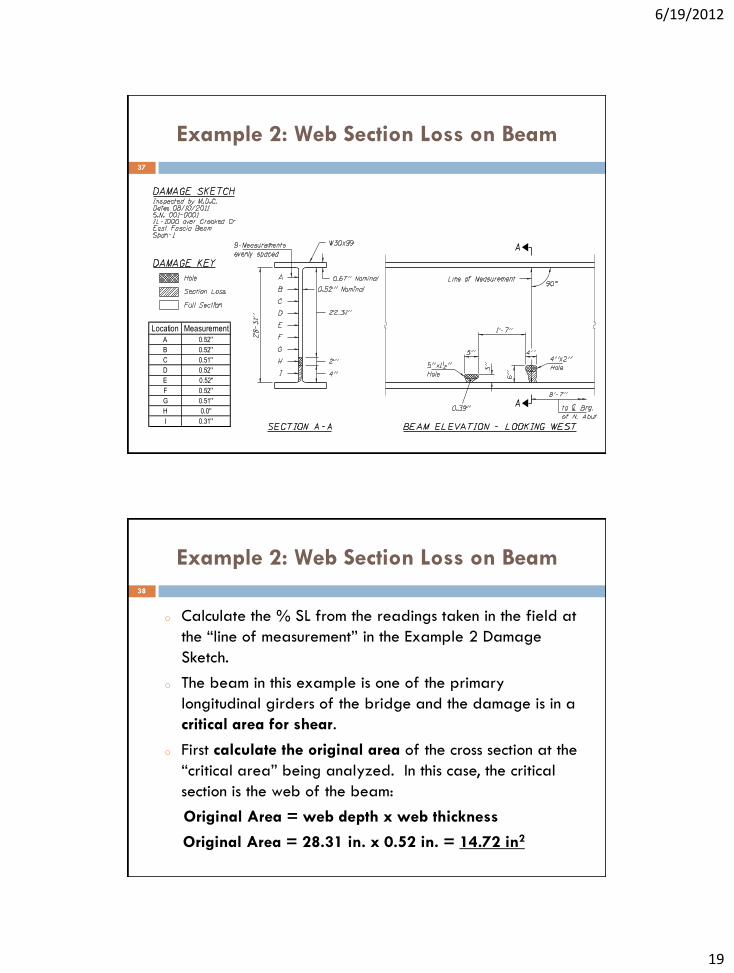
Example 2: Web Section Loss on Beam
Location Measurement
A 0.52''
B 0.52''
C 0.51''
D 0.52''
E 0.52"
F 0.52''
G 0.51''
H 0.0''
I 0.31''
37
Example 2: Web Section Loss on Beam
o Calculate the % SL from the readings taken in the field at
the “line of measurement” in the Example 2 Damage
Sketch.
o The beam in this example is one of the primary
longitudinal girders of the bridge and the damage is in a
critical area for shear.
o First calculate the original area of the cross section at the
“critical area” being analyzed. In this case, the critical
section is the web of the beam:
Original Area = web depth x web thickness
Original Area = 28.31 in. x 0.52 in. = 14.72 in2
38

6/19/2012
20
Example 2: Web Section Loss on Beam
o Next calculate the current area of the element using the measurements shown in the table at the lower left side of the sketch:
Calculate the average current web thickness
Avg. = (sum of the individual readings)/(number of readings)
Avg. = (0.52+0.52+0.51+0.52+0.52+0.52+0.51+0.0+0.31)/9
Avg. = 0.44 in.
Calculate the current area of the web
Current Area = web depth x Avg. current web thickness
Current Area = 28.31” x 0.44” = 12.46 in2
39
Example 2: Web Section Loss on Beam
o An alternate method to calc. the remaining web area when
small sections of SL are present is as follows:
Calculate the current area of the web (Alternate Method)
Current Area = original area – deteriorated area
Current Area = 14.72 in2 – (2”x0.52”) – [4”x(0.52”-0.31”)]
= 12.84 in2 (Note: this method is more accurate)
40

6/19/2012
21
Example 2: Web Section Loss on Beam
o Now calculate the % SL at the element:
%SL = [(original area – current area) / original area] x 100
%SL = [(14.72 – 12.46) / 14.72] x 100 = 15.4 %
o Using the IDOT SIP Manual, Item Number 59 “Steel
Superstructure”, we find that a critical area with 15.4% SL
falls under Condition Rating 4, POOR, which allows section
loss from: 10% < SL ≤ 30%.
41
Example 3: Bearing Section Loss on Beam
Location Measurement
A 0.29
B 0.32
C 0.35
42

6/19/2012
22
Example 3: Bearing Section Loss on Beam
o Calculate the % SL from the readings taken in the field at
the “line of measurement” in the Example 3 Damage Sketch.
o The beam in this example is one of the primary longitudinal
girders of the bridge and the damage is in a critical area
for bearing.
o First calculate the original area of the cross section at the
“critical area” being analyzed. In this case, the critical
section is the web of the beam:
Original Area = web length over bearing x web thickness
Original Area = 9.0 in. x 0.5 in. = 4.5 in2
43
Example 3: Bearing Section Loss on Beam
o Next calculate the current area of the element using the
measurements shown in the table at the lower left side of the
sketch:
Calculate the average current web thickness
Avg. = (sum of the individual readings)/(number of readings)
Avg. = (0.29+0.32+0.35)/3 = 0.32 in.
Calculate the current area of the web over the bearing
Current Area = web length x Avg. current web thickness
Current Area = 9.0” x 0.32” = 2.88 in2
44

6/19/2012
23
Example 3: Bearing Section Loss on Beam
o Now calculate the % SL at the element:
%SL = [(original area – current area) / original area] x 100
%SL = [(4.5 – 2.88) / 4.5] x 100 = 36.0 %
o Using the IDOT SIP Manual, Item Number 59 “Steel
Superstructure”, we find that a critical area with 36.0 % SL
falls under Condition Rating 3, SERIOUS, which allows
section loss from: 30% < SL ≤ 50%.
45
Example 4: Tension Member Section Loss
Location Measurement
A 0.31''
B 0.36''
C 0.39''
D 0.49''
E 0.50''
F 0.48''
G 0.40''
H 0.40''
I 0.34''
J 0.50''
K 0.50''
L 0.48''
46

6/19/2012
24
Example 4: Tension Member Section Loss
o Calculate the % SL from the readings taken in the field at
the “line of measurement” in the Example 4 Damage
Sketch.
o The member in this example is one of the primary vertical
supports of the bridge and the damage is in a critical
area for tension.
o First calculate the original area of the cross section at the
“critical area” being analyzed. In this case, the critical
section is the full area of the double angles:
Original Area = angle area x 4
Original Area = 4.75 in2 x 4 = 19.0 in2
47
Example 4: Tension Member Section Loss
o Next calculate the current area of the element using the
measurements shown in the table at the lower left side of the
sketch:
Calculate the average current damaged angle leg thickness
Avg. = (sum of the individual readings)/(number of readings)
Avg. = (0.31+0.36+0.39+0.40+0.40+0.34)/6 = 0.37 in.
Calculate the current area of the double angles
Current Area = original area – loss area
Current Area = 19.0 in2 – [(0.5”-0.37”)x10.0”] = 17.7 in2
48

6/19/2012
25
Example 4: Tension Member Section Loss
o Now calculate the % SL at the element:
%SL = [(original area – current area) / original area] x 100
%SL = [(19.0 – 17.7) / 19.0] x 100 = 6.8 %
o Using the IDOT SIP Manual, Item Number 59 “Steel
Superstructure”, we find that a critical area with 6.8 % SL
falls under Condition Rating 5, FAIR, which allows section
loss up to 10%.
49
PDH Certificate 50
o A PDH certificate is available to those who
participated in the live version of this webinar.
o To receive a PDH certificate send an email to the
following address: [email protected].
o Title the email “PDH Certificate for IDOT BI Section
Loss Class”
o Include the full name of the individual to receive the
certificate as well as a mailing address in the email.
Top Related