


Languages
Pages
Legal


Manufacturing Processes for Engineering Materials, 5th ed. Kalpakjian • Schmid© 2008, Pearson EducationISBN No. 0-13-227271-7
Bulk Deformation ProcessesProcess General CharacteristicsForging Production of discrete parts with a set of dies; some finishing operations usually
necessary; similar parts can be made by casting and powder-metallurgy techniques;usually performed at elevated temperatures; dies and equipment costs are high;moderate to high labor costs; moderate to high operator skill.
RollingFlat Production of flat plate, sheet, and foil at high speeds, and with good surface finish,
especially in cold rolling; requires very high capital investment; low to moderatelabor cost.
Shape Production of various structural shapes, such as I-beams and rails, at high speeds;includes thread and ring rolling; requires shaped rolls and expensive equipment; lowto moderate labor cost; moderate operator skill.
Extrusion Production of long lengths of solid or hollow products with constant cross-sections,usually performed at elevated temperatures; product is then cut to desired lengths;can be competitive with roll forming; cold extrusion has similarities to forging andis used to make discrete products; moderate to high die and equipment cost; low tomoderate labor cost; low to moderate operator skill.
Drawing Production of long rod, wire, and tubing, with round or various cross-sections;smaller cross-sections than extrusions; good surface finish; low to moderate die,equipment and labor costs; low to moderate operator skill.
Swaging Radial forging of discrete or long parts with various internal and external shapes;generally carried out at room temperature; low to moderate operator skill.
TABLE 6.1 General characteristics of bulk deformation processes.

Manufacturing Processes for Engineering Materials, 5th ed. Kalpakjian • Schmid© 2008, Pearson EducationISBN No. 0-13-227271-7
Upsetting
Manufacturing Processes for Engineering Materials, 5th ed. Kalpakjian • Schmid© 2008, Pearson EducationISBN No. 0-13-227271-7
FIGURE 6.1 (a) Ideal deformation of a solid cylindrical specimen compressed between flat frictionless dies (platens), an operation known as upsetting. (b) Deformation in upsetting with friction at the die-workpiece interfaces. Note barrelling of the billet caused by friction.
(a)
d2
(b)
Workpiece
Die
Die
Friction forces
d0 d1
ho h1
h2 Barreling
h2
d0
ho h1

Manufacturing Processes for Engineering Materials, 5th ed. Kalpakjian • Schmid© 2008, Pearson EducationISBN No. 0-13-227271-7
Grain Flow
FIGURE 6.3 Schematic illustration of grid deformation in upsetting: (a) original grid pattern; (b) after deformation, without friction; (c) after deformation, with friction. Such deformation patterns can be used to calculate the strains within a deforming body.
(a)
(b)
(c)
FIGURE 6.2 Grain flow lines in upsetting a solid, steel cylindrical specimen at elevated temperatures between two flat cool dies. Note the highly inhomogeneous deformation and barreling, and the difference in shape of the bottom and top sections of the specimen. The latter results from the hot specimen resting on the lower die before deformation proceeds. The lower portion of the specimen began to cool, thus exhibiting higher strength and hence deforming less than the top surface. Source: After J.A. Schey.

Manufacturing Processes for Engineering Materials, 5th ed. Kalpakjian • Schmid© 2008, Pearson EducationISBN No. 0-13-227271-7
Slab Analysis of Forging
dx
x
a
(a) (b)
!y
!x + d!x
!z
!z =!x + !y
2
(c)
h1
!y
!y
!y
µ!y
µ!y
!x!x !x
FIGURE 6.1 Stresses on an element in plane-strain compression (forging) between flat dies with fric-tion. The horizontal stress x is assumed to be uniformly distributed along the height h of the ele-ment. Identifying the stresses on an element (slab) is the first step in the slab method of analysis of metalworking processes.
(σx+dσx)h+2µσydx!σyh= 0
σx = σy!Y " = Y "!e2µ(a!x)/h!1
"
From equilibrium:
Resulting die pressure prediction:

Manufacturing Processes for Engineering Materials, 5th ed. Kalpakjian • Schmid© 2008, Pearson EducationISBN No. 0-13-227271-7
Die Pressure
FIGURE 6.5 Distribution of die pressure, in dimensionless form of p/Y’, in plane-strain compression with sliding friction. Note that the pressure at the left and right boundaries is equal to the yield stress of the material in plane strain, Y’. Sliding friction means that the frictional stress is directly proportional to the normal stress.
Workpiece
ax
h
p/Y!
e2 a/h
1
0
FIGURE 6.6 Die pressure distribution in compressing a rectangular workpiece with sliding friction and under conditions of plane stress, using the distortion-energy criterion. Note that the stress at the corners is equal to the uniaxial yield stress, Y, of the material.
Y
Pressure distribution
Workpiece
FIGURE 6.7 Increase in die-workpiece contact area of an originally rectangular specimen (v iewed f rom the top) compressed between flat dies and with friction. Note that the length of the specimen (horizontal dimension) has increased proportionately less than its width (vertical dimension). Likewise, a specimen originally in the shape of a cube acquires the shape of a pancake after deformation with friction.
Original contact area
After first reduction
After second reduction

Manufacturing Processes for Engineering Materials, 5th ed. Kalpakjian • Schmid© 2008, Pearson EducationISBN No. 0-13-227271-7
Slab Method for Cylindrical Workpiece
FIGURE 6.8 Stresses on an element in forging of a solid cylindrical workpiece between flat dies and with friction. Compare this figure and the stresses involved with Fig. 6.4.
xr
dx
(a) (b)
h !r
!z
µ!z
!z !"
!"
!r 1 d!rd"
d"
2
d"
2 Results:
Average pressure:
Forging force:
p= Ye2µ(r!x)/h.
pav ! Y!1+
2µr3h
".
F = (pav)!πr2
"

Manufacturing Processes for Engineering Materials, 5th ed. Kalpakjian • Schmid© 2008, Pearson EducationISBN No. 0-13-227271-7
Die Pressure
FIGURE 6.9 Ratio of average die pressure to yield stress as a function of friction and aspect ratio of the specimen: (a) plane-strain compression; and (b) compression of a solid cylindrical specimen. Note that the yield stress in (b) is Y, and not Y’ as it is in the plane-strain compression shown in (a). Source: After J.F.W. Bishop.
Sticking = 0.2
0.1 0.05
0
12
10
8
6
4
2
0
Y!
pav
(a)
0 10 20 30 40 50 60 70 80
Y
pav
2rh
2ah
0 10 20 30 40 50 60 70 80
12
10
8
6
4
2
0
(b)
Sticking = 0.3
0.20.15
0.1
0.05
0.02
0

Manufacturing Processes for Engineering Materials, 5th ed. Kalpakjian • Schmid© 2008, Pearson EducationISBN No. 0-13-227271-7
Pressure with Sticking Condition
FIGURE 6.10 Distribution of dimensionless die pressure, p/Y’, in compressing a rectangular specimen in plane strain and under sticking conditions. Sticking means that the frictional (shear) stress at the interface has reached the shear yield stress of the material. Note that the pressure at the edges is the uniaxial yield stress of the material in plane strain, Y’.
Workpiece x
p/Y !
1
0
h
(1 + a/h)
a
Results for sticking friction in plane strain:
Results for sticking friction with cylinder:
p= Y !!1+
a" xh
"
p= Y!1+
r! xh
"

Manufacturing Processes for Engineering Materials, 5th ed. Kalpakjian • Schmid© 2008, Pearson EducationISBN No. 0-13-227271-7
Finite Element Analysis
FIGURE 6.11 Deformation of a blank during forging as predicted by the software program DEFORM based on the finite-element method of analysis. Source: Courtesy Scientific Forming Technologies Corporation.
(a) (b)
(c) (d)
Upper die
Lower die
Workpiece

Manufacturing Processes for Engineering Materials, 5th ed. Kalpakjian • Schmid© 2008, Pearson EducationISBN No. 0-13-227271-7
Die Pressure and Aspect Ratio
FIGURE 6.12 Die pressure required in various metalworking operations and under frictionless plane-strain conditions, as obtained by the slip-line analysis. Note that the magnitude of the die-workpiece contact area is an important factor in determining pressures. Source: After W.A. Backofen.
0 1 32 4 5 6 7 8 9 100
1
2
3
h
L
= h/L
p/Y! = 1 + /2
p
Y!
Sheet and striprolling
Wire and rod drawing
ExtrusionBreakdown
rollingHeavyforging
PiercingHardness
testing

Manufacturing Processes for Engineering Materials, 5th ed. Kalpakjian • Schmid© 2008, Pearson EducationISBN No. 0-13-227271-7
Plane Strain Examples
FIGURE 6.13 Examples of plastic deformation processes in plane strain, showing the h/L ratio. (a) Indenting with flat dies, an operation similar to the cogging process, as shown in Fig. 6.19. (b) Drawing or extrusion of a strip with a wedge-shaped die, as described in Sections 6.4 and 6.5. (c) Ironing; see also 7.53. (d) Rolling, described in Section 6.3.
L
h
(a)
D = L
h
d0 or ho
!
d1 or h1
h
L
!ho
h1
(c) (d)
L
R
h1ho
(b)
h
D = L
h

Manufacturing Processes for Engineering Materials, 5th ed. Kalpakjian • Schmid© 2008, Pearson EducationISBN No. 0-13-227271-7
Impression Die Forging
FIGURE 6 .14 Schemat ic illustrations of stages in impression-die forging. Note the formation of a flash, or excess material that subsequently has to be trimmed off.
(a) (b) (c)
Die
Blank
Die
(d)
Flash
Simple shapes, without flash 3-5Simple shapes, with flash 5-8Complex shapes, with flash 8-12
TABLE 6.2 Range of Kp values in Eq. (6.22) for impression-die forging.
F = KpYfA
Forging force:

Manufacturing Processes for Engineering Materials, 5th ed. Kalpakjian • Schmid© 2008, Pearson EducationISBN No. 0-13-227271-7
Load-Stroke Curve
FIGURE 6.15 Typical load-stroke curve for impression-die forging. Note the sharp increase in load when the flash begins to form. Source: After T. Altan.
Diemotion
Workpiece
CLDie
(a)
Upsetting
Filling
End
Flash
Cavity filled completely
Dies closed
Forgingenergy
Flash begins to form
Dies contactworkpiece
Forgingcompleted
Forging strokeF
org
ing lo
ad
(b)
Land
Manufacturing Processes for Engineering Materials, 5th ed. Kalpakjian • Schmid© 2008, Pearson EducationISBN No. 0-13-227271-7
Orbital-Forging
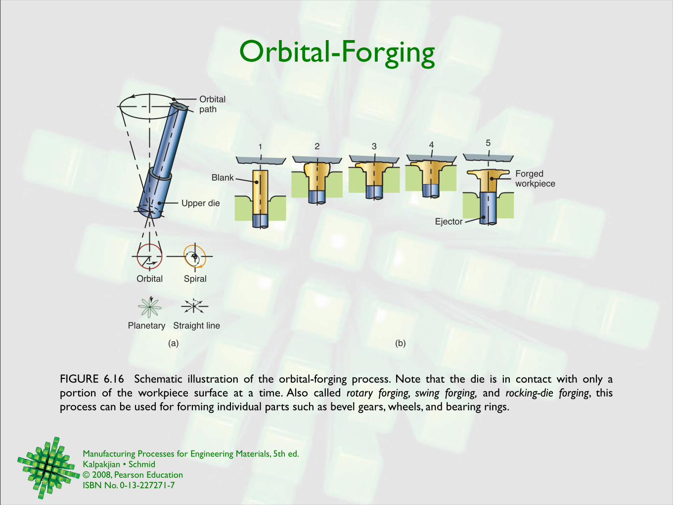
FIGURE 6.16 Schematic illustration of the orbital-forging process. Note that the die is in contact with only a portion of the workpiece surface at a time. Also called rotary forging, swing forging, and rocking-die forging, this process can be used for forming individual parts such as bevel gears, wheels, and bearing rings.
(a) (b)
1 2 3 4 5
Orbitalpath
Upper die
Blank
Orbital
Planetary Straight line
Spiral
Forgedworkpiece
Ejector
Manufacturing Processes for Engineering Materials, 5th ed. Kalpakjian • Schmid© 2008, Pearson EducationISBN No. 0-13-227271-7
Heading & Piercing
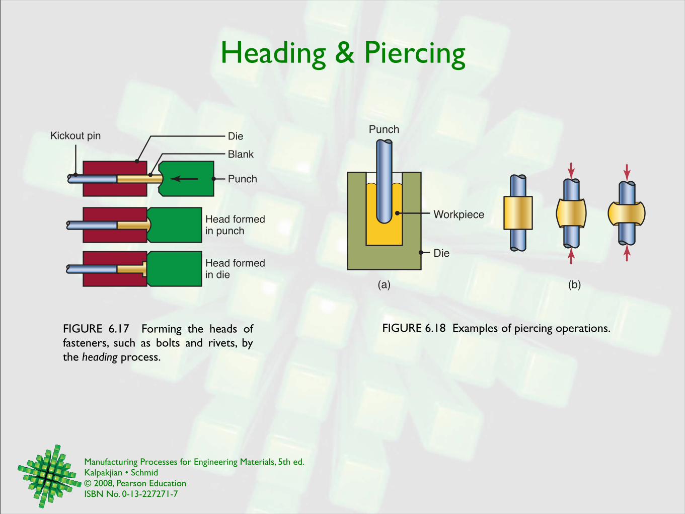
FIGURE 6.18 Examples of piercing operations.
Head formedin die
Head formedin punch
Kickout pin Die
Blank
Punch
FIGURE 6.17 Forming the heads of fasteners, such as bolts and rivets, by the heading process.
Workpiece
(a) (b)
Die
Punch

Manufacturing Processes for Engineering Materials, 5th ed. Kalpakjian • Schmid© 2008, Pearson EducationISBN No. 0-13-227271-7
Open-Die Forging
FIGURE 6.19 (a) Schematic illustration of a cogging operation on a rectangular bar. Blacksmiths use a similar procedure to reduce the thickness of parts in small increments by heating the workpiece and hammering it numerous times along the length of the part. (b) Reducing the diameter of a bar by open-die forging; note the movements of the die and the workpiece. (c) The thickness of a ring being reduced by open-die forging.
(a)
Workpiece Workpiece
(b) (c)
Workpiece
Die
Die
Die Die
Die
Die

Manufacturing Processes for Engineering Materials, 5th ed. Kalpakjian • Schmid© 2008, Pearson EducationISBN No. 0-13-227271-7
Roll Forging
FIGURE 6.21 Two illustrations of roll forging (cross-rolling) operations. Tapered leaf springs and knives can be made by this process using specially designed rolls. Source: After J. Holub.
Workpiece
Shaped roll
Workpiece
(b)(a)

Manufacturing Processes for Engineering Materials, 5th ed. Kalpakjian • Schmid© 2008, Pearson EducationISBN No. 0-13-227271-7
Production of Ball Bearings
FIGURE 6.21 (a) Production of steel balls for bearings by skew rolling. (b) Production of steel balls by upsetting of a short cylindrical blank; note the formation of flash. The balls are subsequently ground and polished to be used as ball bearings and similar components.
Semi-finishedball
Stock
(b)(a)
Die
Ejector
Blank Ball

Manufacturing Processes for Engineering Materials, 5th ed. Kalpakjian • Schmid© 2008, Pearson EducationISBN No. 0-13-227271-7
Forging Defects
FIGURE 6.22 Stages in lap formation in a part during forging, due to buckling of the web. Web thickness should be increased to avoid this problem.
1. Blocked forging
Die Die
2. Begin finishing
Rib Web
3. Web buckles
Laps
4. Laps in finished forging
FIGURE 6.23 Stages in internal defect formation in a forging because of an oversized billet. The die cavities are filled prematurely, and the material at the center of the part flows radially outward and past the filled regions as deformation continues.
2. Die cavities are being filled
1. Forging begins 3. Cracks develop in ribs
4. Cracks propagate through ribs
Manufacturing Processes for Engineering Materials, 5th ed. Kalpakjian • Schmid© 2008, Pearson EducationISBN No. 0-13-227271-7
Effect of Radius
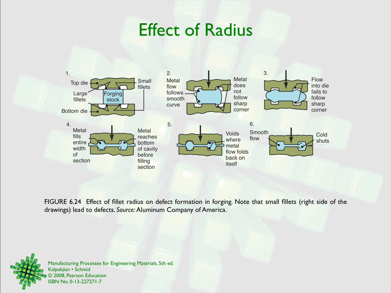
FIGURE 6.24 Effect of fillet radius on defect formation in forging. Note that small fillets (right side of the drawings) lead to defects. Source: Aluminum Company of America.
Top die
Largefillets
Bottom die
Forgingstock
Smallfillets
1.
Metalflowfollowssmoothcurve
Metaldoesnotfollowsharpcorner
2.Flowinto diefails tofollowsharpcorner
3.
Metalreachesbottomof cavitybeforefillingsection
Metalfillsentirewidthofsection
4.
Voidswheremetalflow foldsback onitself
Coldshuts
Smoothflow
6.5.

Manufacturing Processes for Engineering Materials, 5th ed. Kalpakjian • Schmid© 2008, Pearson EducationISBN No. 0-13-227271-7
Forging Dies
FIGURE 6.26 Standard terminology for various features of a typical forging die.
External and internal draft angles
Flash
Parting line
Land
Rib Web
Fillet
Corner
Trim line
Partingline
Gutter
FIGURE 6.25 Stages in forging a connecting rod for an internal combustion engine. Note the amount of flash developed, which is important in properly filling die cavities.
(a)
Edging
Trimming
Blank (bar stock)
Blocking
Finishing
1.
2.
3.
4.
5.

Manufacturing Processes for Engineering Materials, 5th ed. Kalpakjian • Schmid© 2008, Pearson EducationISBN No. 0-13-227271-7
Forging Temperatures
Metal !C !FAluminum alloys 400-450 750-850Copper alloys 625-950 1150-1750Nickel alloys 870-1230 1600-2250Alloy steels 925-1260 1700-2300Titanium alloys 750-795 1400-1800Refractory alloys 975-1650 1800-3000
TABLE 6.3 Forging temperature ranges for various metals.

Manufacturing Processes for Engineering Materials, 5th ed. Kalpakjian • Schmid© 2008, Pearson EducationISBN No. 0-13-227271-7
Metalworking Equipment
FIGURE 6.27 Schematic illustration of various types of presses used in metalworking. The choice of a press is an important consideration in the overall operation and productivity.
Ram
Crank
Ram
Fluid
Hydraulic
Ram
Knucklejoint
Flywheel
Frictiondrive
Screw
Ram
Screw
(a) (b) (c) (d)
Manufacturing Processes for Engineering Materials, 5th ed. Kalpakjian • Schmid© 2008, Pearson EducationISBN No. 0-13-227271-7
Rolling Operations
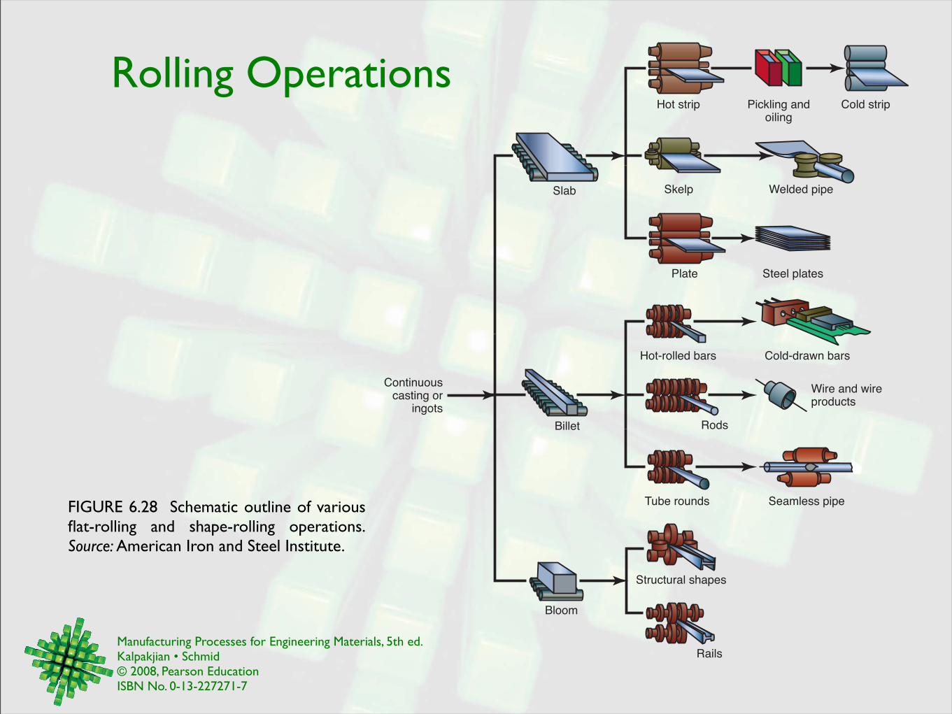
FIGURE 6.28 Schematic outline of various flat-rolling and shape-rolling operations. Source: American Iron and Steel Institute.
Continuouscasting or
ingots
Slab
Billet
Bloom
Hot strip Pickling andoiling
Cold strip
Skelp
Plate
Welded pipe
Steel plates
Hot-rolled bars Cold-drawn bars
Wire and wireproducts
Rods
Tube rounds Seamless pipe
Rails
Structural shapes

Manufacturing Processes for Engineering Materials, 5th ed. Kalpakjian • Schmid© 2008, Pearson EducationISBN No. 0-13-227271-7
Grain Structure in Hot Rolling
FIGURE 6.29 Changes in the grain structure of metals during hot rolling. This is an effective method to reduce grain size and refine the microstructure in metals, resulting in improved strength and good ductility. In this process cast structures of ingots or continuous castings are converted to a wrought structure.
(a) (b)
Deformed elongated grains
New grains forming
Wrought product with
small, uniform grains
Recrystallization complete
New grains growing
Ingot with nonuniform
grains
Hot rolling
Wrought product with large grains

Manufacturing Processes for Engineering Materials, 5th ed. Kalpakjian • Schmid© 2008, Pearson EducationISBN No. 0-13-227271-7
Mechanics of Rolling
FIGURE 6.30 Schematic illustration of the flat-rolling process. (Note that the top roll has been removed for clarity.)
Workpiece
V0
Vf
Vr
ho
R
hf
RollL
(Top roll removed)wo
wf
FIGURE 6.31 Relative velocity distribution between roll and strip surfaces. The arrows represent the frictional forces acting along the strip-roll interfaces. Note the difference in their direction in the left and right regions.
Vf
Vr !
Roll
V0
V0
Vr
Vf
Workpiece
Forward slip:
Forward slip=Vf !VrVr
Manufacturing Processes for Engineering Materials, 5th ed. Kalpakjian • Schmid© 2008, Pearson EducationISBN No. 0-13-227271-7
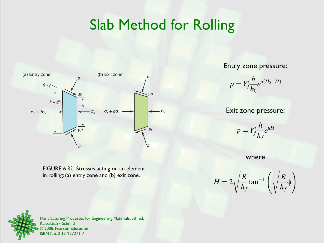
Slab Method for Rolling
FIGURE 6.32 Stresses acting on an element in rolling: (a) entry zone and (b) exit zone.
h + dhh
p
p
p
p
x + d x x
(a) Entry zonep
p
p
p
x + d x x
(b) Exit zone
Entry zone pressure:
Exit zone pressure:
p= Y !fhh0eµ(H0"H)
p= Y !fhh feµH
where
H = 2
!Rhftan!1
"!Rhfφ
#

Manufacturing Processes for Engineering Materials, 5th ed. Kalpakjian • Schmid© 2008, Pearson EducationISBN No. 0-13-227271-7
Pressure Distribution in Rolling
FIGURE 6.33 Pressure distribution in the roll gap as a function of the coefficient of friction. Note that as friction increases, the neutral point shifts toward the entry. Without friction, the rolls will slip, and the neutral point shifts completely to the exit. (See also Table 4.1.)
0.150.1
0.075
Rolling direction
Entry Exit
4
3
2
1
0
p
Y !
L
=0.4
0.3
0.2
FIGURE 6.35 Pressure distribution as a function of front and back tension in rolling. Note the shifting of the neutral point and the reduction in the area under the curves (hence reduction in the roll force) as tensions increase.
Rolling direction
p
Y�
4
3
2
1
0
Entry Exit
L1L2
L3
L
Redu
ctio
n = 5
0%
30
2010
FIGURE 6.34 Pressure distribution in the roll gap as a function of reduction in thickness. Note the increase in the area under the curves with increasing reduction, thus increasing the roll force.
p
!b
!b
!f
!f"
#n0
ho /2hf /2 !f!b

Manufacturing Processes for Engineering Materials, 5th ed. Kalpakjian • Schmid© 2008, Pearson EducationISBN No. 0-13-227271-7
Roll Bending & Slab Spread
FIGURE 6.36 (a) Bending of straight cylindrical rolls (exaggerated) because of the roll force. (b) Bending of rolls, ground with camber, that produce a sheet of uniform thickness during rolling.
(b)
Strip withuniform thickness
Strip thickerat center
Rolls
(a)
FIGURE 6.37 Increase in the width of a strip (spreading) during flat rolling. Spreading can be similarly observed when dough is rolled on a flat surface with a rolling pin.
hf
Side view
Top view
ho wo wf
(b) (a)

Manufacturing Processes for Engineering Materials, 5th ed. Kalpakjian • Schmid© 2008, Pearson EducationISBN No. 0-13-227271-7
Defects in Rolling
FIGURE 6.38 Schematic illustration of some defects in flat rolling: (a) wavy edges; (b) zipper cracks in the center of strip; (c) edge cracks; (d) alligatoring.
Rolling direction
(a) (b)
(c) (d)
FIGURE 6.39 The effect of roll radius on the type of residual stresses developed in flat rolling: (a) small rolls and/or small reduction in thickness; and (b) large rolls and/or large reduction in thickness.
Sheet thickness
Tension Compression Tension Compression
(a) (b)

Manufacturing Processes for Engineering Materials, 5th ed. Kalpakjian • Schmid© 2008, Pearson EducationISBN No. 0-13-227271-7
Roller Leveling
FIGURE 6.40 Schematic illustrations of roller leveling to (a) flatten rolled sheets and (b) straighten round rods.
Leveling rolls
(a) (b)
Rod
Rollers
Sheet

Manufacturing Processes for Engineering Materials, 5th ed. Kalpakjian • Schmid© 2008, Pearson EducationISBN No. 0-13-227271-7
Roll Arrangements
FIGURE 6.41 Schematic illustration of various roll arrangements: (a) two-high mill; (b) three-high mill; (c) four-high mill; (d) tandem rolling, with three stands; (e) planetary mill, (f) cluster (Sendzimir) mill.
(f)
(d)
Support roll
CagePlanetary
rolls
(e)
(c)
Screw orhydraulic
mechanism
Work rolls
Back-up rolls
Chocks
Back-up rolls
Housing
(a) (b)
Backing bearing
Driven roll
Driven roll
Driven roll
Bearing shaft
Work roll
Strip
Firstintermediate rollSecond
intermediate roll
Driven roll
Housing

Manufacturing Processes for Engineering Materials, 5th ed. Kalpakjian • Schmid© 2008, Pearson EducationISBN No. 0-13-227271-7
Shape Rolling
FIGURE 6.42 Stages in shape rolling of an H-section. Several other structural sections, such as channels and rails, also are rolled by this process.
Stage 1 Stage 2
Blooming rolls
Stage 3
Stage 4 Stage 5 Stage 6
Edging rolls Roughing horizontal and vertical rolls
Intermediate horizontaland vertical rolls
Edging rolls Finishing horizontal and vertical rolls

Manufacturing Processes for Engineering Materials, 5th ed. Kalpakjian • Schmid© 2008, Pearson EducationISBN No. 0-13-227271-7
Ring Rolling
FIGURE 6.43 (a) Schematic illustration of a ring-rolling operation. Reducing the ring thickness results in an increase in its diameter. (b)-(d) Three examples of cross-sections that can be produced by ring rolling.
(c) (a)
Main roll (driven)
Rounding roll
Idler roll
Workpiece
Edging roll
(b) (d)

Manufacturing Processes for Engineering Materials, 5th ed. Kalpakjian • Schmid© 2008, Pearson EducationISBN No. 0-13-227271-7
Thread Rolling
FIGURE 6.44 Thread-rolling processes: (a) and (b) reciprocating flat dies and (c) two-roller dies; (d) thread-rol led par ts , made economically and at high production rates. Source: (d) Courtesy of Tesker Manufacturing Corp.
Moving die
Threaded part
Stationary die
Blank
(c)
(b)(a)
(d)
Work rest
Movingcylindrical die
Force
Workpiece Stationary
cylindrical
die

Manufacturing Processes for Engineering Materials, 5th ed. Kalpakjian • Schmid© 2008, Pearson EducationISBN No. 0-13-227271-7
Thread Microstructure
FIGURE 6.45 (a) Schematic illustration of thread features; (b) grain-flow lines in machined and (c) rolled threads. Note that unlike machined threads, which are cut through the grains of the metal, rolled threads follow the grains and because of the cold working involved, they are stronger.
Machined thread Rolled thread
(b) (c)(a)
Diameter of bar
Machined or rolled thread
Minordiameter
Majordiameter
Manufacturing Processes for Engineering Materials, 5th ed. Kalpakjian • Schmid© 2008, Pearson EducationISBN No. 0-13-227271-7
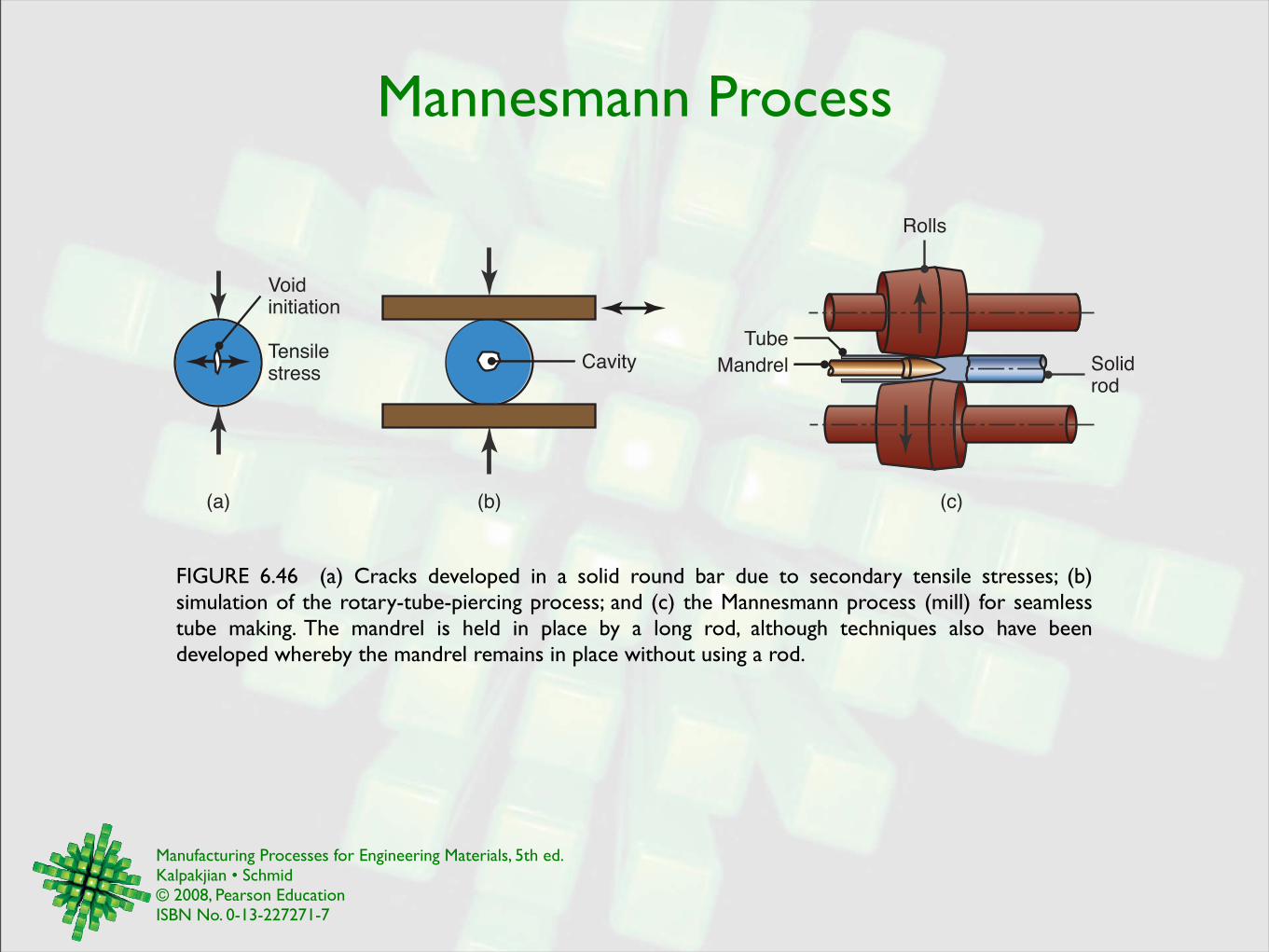
Mannesmann Process
FIGURE 6.46 (a) Cracks developed in a solid round bar due to secondary tensile stresses; (b) simulation of the rotary-tube-piercing process; and (c) the Mannesmann process (mill) for seamless tube making. The mandrel is held in place by a long rod, although techniques also have been developed whereby the mandrel remains in place without using a rod.
Tube
Solidrod
Rolls
Voidinitiation
Tensilestress Mandrel
(a) (b) (c)
Cavity

Manufacturing Processes for Engineering Materials, 5th ed. Kalpakjian • Schmid© 2008, Pearson EducationISBN No. 0-13-227271-7
Types of Extrusion
FIGURE 6.47 Types of extrusion: (a) direct; (b) indirect; (c) hydrostatic; (d) impact.
(a)
(c) (d)
Punch
Extrudedtube
Container liner Container
Billet
Pressing stem
Dummy blockExtrusion
Die
Die backer
BilletDummy block
Backing disc
Container
DieExtrusion
Tool stem
Container liner
Container
Die
Extrusion Die backer
Fluid
Pressing stem
Seals

Manufacturing Processes for Engineering Materials, 5th ed. Kalpakjian • Schmid© 2008, Pearson EducationISBN No. 0-13-227271-7
Extruded Products
FIGURE 6.48 (a)-(c) Examples of extrusions and products made by sectioning them. Source: Kaiser Aluminum. (d) Examples of extruded cross-sections. Source: (d) Courtesy of Plymouth Extruded Shapes.
(d)
(a)
(b)
(c)

Manufacturing Processes for Engineering Materials, 5th ed. Kalpakjian • Schmid© 2008, Pearson EducationISBN No. 0-13-227271-7
Metal Flow in Extrusion
FIGURE 6.49 Schematic illustration of three different types of metal flow in direct extrusion. The die angle in these illustrations is 90°.
(a)
(b)
(c)
Deadzone
Deadzone
Slab method prediction for extrusion pressure:
Extrusion pressure with 45° dead-metal zone:
p= Y!1+
tanαµ
"#Rµcotα!1
$
p= Y!1.7lnR+
2LDo
"

Manufacturing Processes for Engineering Materials, 5th ed. Kalpakjian • Schmid© 2008, Pearson EducationISBN No. 0-13-227271-7
Mechanics of Extrusion
FIGURE 6.50 Schematic illustration of typical extrusion pressure as a function of ram travel: (a) direct extrusion and (b) indirect extrusion. The pressure in direct extrusion is higher because of frictional resistance at the container-bi l let interfaces , which decreases as the billet length decreases in the container.
Ram travelExtr
usio
n p
ressure
ab
FIGURE 6.52 Schematic illustration of the effect of temperature and ram speed on extrusion pressure. Note the similarity of this figure with Fig. 2.10.
FIGURE 6.51 Schematic illustration of extrusion force as a function of die angle: (a) total force; (b) ideal force; (c) force required for redundant deformation; (d) force required to overcome friction. Note that there is a die angle where the total extrusion force is a minimum (optimum die angle).
Extr
usio
n p
ressure
Extrusion speed (log)
Increasingtemperature
a
c
d
Die angle (!)
Extr
usio
n forc
e
b

Manufacturing Processes for Engineering Materials, 5th ed. Kalpakjian • Schmid© 2008, Pearson EducationISBN No. 0-13-227271-7
Extrusion Constant
FIGURE 6.51 Extrusion constant, Ke, for various materials as a function of temperature. Source: After P. Loewenstein.
Temperature (°F)
1000 1500 2000 25000
20
40
60
80400 600 800 1000 1200 1400
400
200
°C
MP
a
Extr
usio
n c
on
sta
nt,
kc (
10
3 p
si)
Copper
70–30 Brass
Molybdenum
C
hro
miu
m
1100 Aluminum
Beryllium
Cold-rolledsteel
p= Ke lnR

Manufacturing Processes for Engineering Materials, 5th ed. Kalpakjian • Schmid© 2008, Pearson EducationISBN No. 0-13-227271-7
Cold Extrusion
FIGURE 6.54 Two examples of cold extrusion. Arrows indicate the direction of material flow. These parts may also be considered as forgings.
Workpiece
Die
(a) (b)
Punch
Punch

Manufacturing Processes for Engineering Materials, 5th ed. Kalpakjian • Schmid© 2008, Pearson EducationISBN No. 0-13-227271-7
Impact Extrusion
FIGURE 6.55 (a)-(b) Schematic illustration of the impact-extrusion process. The extruded parts are stripped using a stripper plate, as otherwise they may stick to the punch. (c) Two examples of products made by impact extrusion. Collapsible tubes can be produced by impact extrusion, referred to as the Hooker process.
(c)(a) (b)
Stripperplate
Die
Blank
Punch
Die
Clearance

Manufacturing Processes for Engineering Materials, 5th ed. Kalpakjian • Schmid© 2008, Pearson EducationISBN No. 0-13-227271-7
Extrusion Pressure
2 4 7 12 16
12
8
4
0
900
600
300
0
0.7 1.5 2.0 2.5
Maxim
um
extr
usio
n p
ressure
(psi x 1
04)
MP
a
Extrusion ratio (R)
True strain, !
a
b
c
dFIGURE 6.56 Extrusion pressure as a function of the extrusion ratio for an alu-minum alloy. (a) Direct extrusion, =90°. (b) Hydrostatic extrusion, =45°. (c) Hydrostatic extrusion, =22.5°. (d) Ideal homogeneous deformation, calculated. Source: After H. Li, D. Pugh, and K. Ashcroft.

Manufacturing Processes for Engineering Materials, 5th ed. Kalpakjian • Schmid© 2008, Pearson EducationISBN No. 0-13-227271-7
Chevron Cracking Defect
FIGURE 6.57 a) Chevron cracking in round steel bars during extrusion. Unless the part is inspected, such internal detects may remain undetected and possibly cause failure of the part in service. (b) Deformation zone in extrusion, showing rigid and plastic zones. Note that the plastic zones do not meet, leading to chevron cracking. The same observations are also made in drawing round bars through conical dies and drawing flat sheet or plate through wedge-shaped dies. Source: After B. Avitzur.
Die
Rigidbillet
Central burst
Rigid product
Vf
Vo
Plasticdeformation zone
(a) (b)

Manufacturing Processes for Engineering Materials, 5th ed. Kalpakjian • Schmid© 2008, Pearson EducationISBN No. 0-13-227271-7
Tube Extrusion
FIGURE 6.58 Extrusion of a seamless tube. (a) Using an internal mandrel that moves independently of the ram. An alternative arrangement has the mandrel integral with the ram. (b) Using a spider die (see Fig. 6.59c) to produce seamless tubing.
Tube
Mandrel Container
Ram
Billet
Billet
ContainerDie
Spider
Mandrel
Tube
RamDie
Spider
Mandrel
(a) (b)

Manufacturing Processes for Engineering Materials, 5th ed. Kalpakjian • Schmid© 2008, Pearson EducationISBN No. 0-13-227271-7
Extrusion of Hollow Shapes
FIGURE 6.59 (a) An extruded 6063-T6 aluminum ladder lock for aluminum extension ladders. This part is 8 mm (5/16 in.) thick and is sawed from the extrusion, as also shown in Fig. 6.48a. (b)-(d) Components of various types of dies for extruding intricate hollow shapes. Source: After K. Laue and H. Stenger
(a)
Weldingchamber
Spider BridgeDie Spider
Porthole die
Inletports
Spider die Bridge die
(b) (c) (d)
Die

Manufacturing Processes for Engineering Materials, 5th ed. Kalpakjian • Schmid© 2008, Pearson EducationISBN No. 0-13-227271-7
Rod or Wire Drawing
FIGURE 6.60 Variables in drawing round rod or wire.
Dieangle
Die
Wire or rod
FAfAo
Land
!
Land
Relief angle
Workpiece
!

Manufacturing Processes for Engineering Materials, 5th ed. Kalpakjian • Schmid© 2008, Pearson EducationISBN No. 0-13-227271-7
Slab Analysis for Drawing
FIGURE 6.61 Stresses acting on an element in drawing of a solid cylindrical rod or wire through a converging conical die.
p
p
µp
µp
!x!x + d!x
(D + dD)DD
0 Df
x"
dx
Drawing stress
Inhomogeneity factor
Φ= 1+0.12!hL
"
σd =ΦY!1+
µα
"ln
#AoAf
$

Manufacturing Processes for Engineering Materials, 5th ed. Kalpakjian • Schmid© 2008, Pearson EducationISBN No. 0-13-227271-7
Drawing Stress
FIGURE 6.63 The effect of reduction in cross-sectional area on the optimum die angle in drawing. Source: After J.G. Wistreich.
Dra
win
g s
tre
ss
Die
pre
ssu
reEntry Exit
Without back tension
With back tension
(a) (b)
FIGURE 6.62 Variation in the (a) drawing stress and (b) die contact pressure along the deformation zone. Note that as the drawing stress increases, the die pressure decreases (see also yield criteria, described in Section 2.11). Note the effect of back tension on the stress and pressure.
Reduction (%)45
40
35
30
25
20
15
10
5 Optimumdie angle
0.8
0.6
0.4
0.2
0
d
Y
0 4 8 12 16
Die angle, (deg)
Manufacturing Processes for Engineering Materials, 5th ed. Kalpakjian • Schmid© 2008, Pearson EducationISBN No. 0-13-227271-7
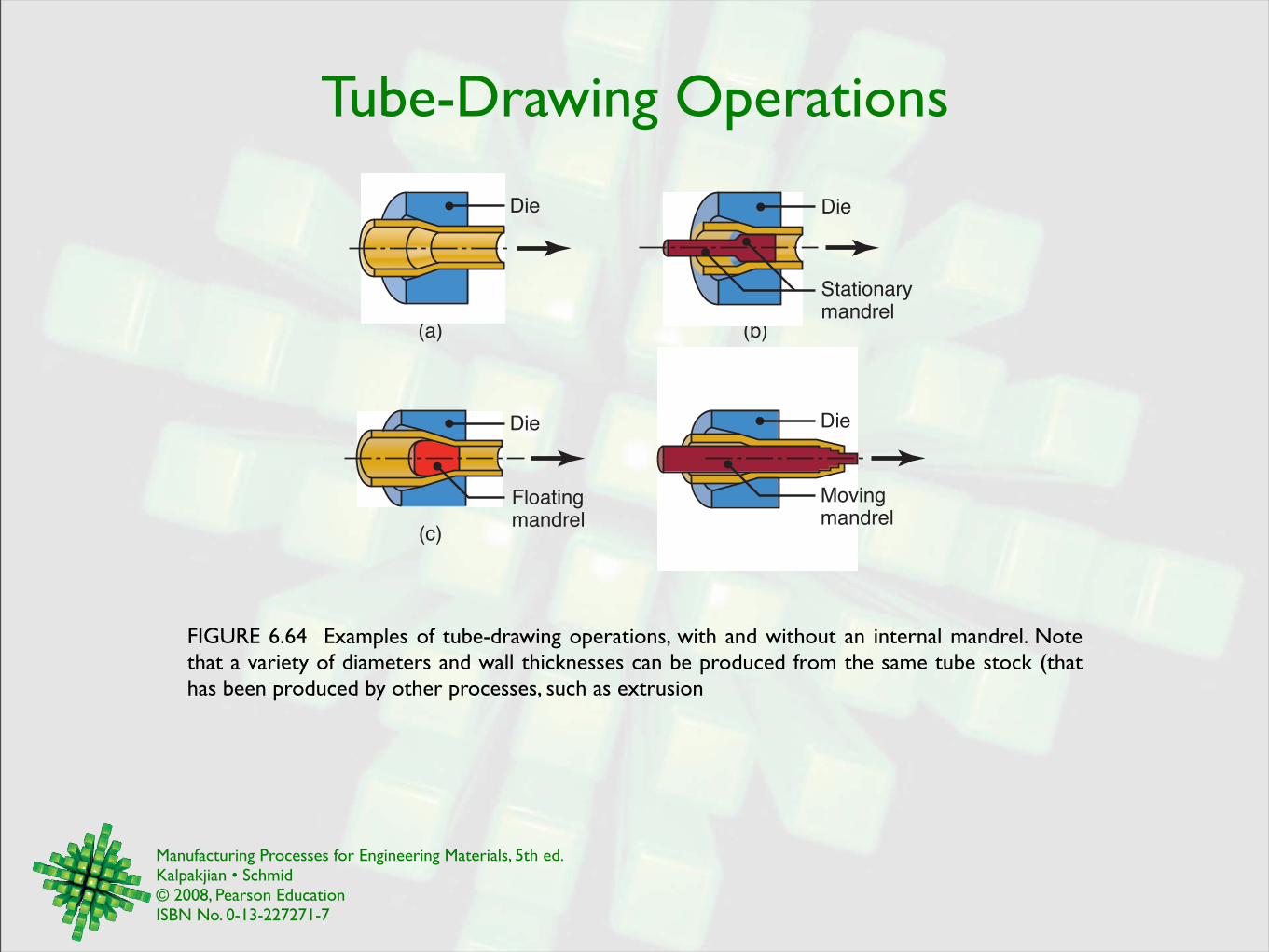
Tube-Drawing Operations
FIGURE 6.64 Examples of tube-drawing operations, with and without an internal mandrel. Note that a variety of diameters and wall thicknesses can be produced from the same tube stock (that has been produced by other processes, such as extrusion
(a)
(d)(c)
(b)
Die
Stationarymandrel
Die
Floatingmandrel
Die
Movingmandrel
Die

Manufacturing Processes for Engineering Materials, 5th ed. Kalpakjian • Schmid© 2008, Pearson EducationISBN No. 0-13-227271-7
Residual Stresses in Drawing
FIGURE 6.65 Residual stresses in cold-drawn 1045 carbon steel round rod: T = transverse direction, L = longitudinal direction and R = radial direction. Source: After E.S. Nachtman.
Distance from center (in.)
0.75 0 0.75
60
40
20
0
220
240
260
280
Resid
ual str
ess (
psi x 1
03)
Tensio
nC
om
pre
ssio
n
400
200
0
2200
2400
MP
a
Rod diametermm
19 0 19
T
L
R

Manufacturing Processes for Engineering Materials, 5th ed. Kalpakjian • Schmid© 2008, Pearson EducationISBN No. 0-13-227271-7
Drawing Dies
FIGURE 6.66 (a) Terminology for a typical die for drawing round rod or wire. (b) Tungsten-carbide die insert in a steel casing. Diamond dies, used in drawing thin wire, also are encased in a similar manner.
(a) (b)
Bell (angle or radius)
Drawingdirection
Entering angle
Approach angle
Bearing surface (land)
Back relief angleTungsten-carbideinsert (nib)
Steel casing
Drawingdirection
FIGURE 6.67 Schematic illustration of a typical wear pattern in a wire-drawing die.
Diameter of incoming wire
Unused
Worn die

Manufacturing Processes for Engineering Materials, 5th ed. Kalpakjian • Schmid© 2008, Pearson EducationISBN No. 0-13-227271-7
Rotary Swaging
FIGURE 6.68 (a) Schematic illustration of the rotary-swaging process. (b) Forming internal profiles in a tubular workpiece by swaging.
(b)
Cam
Die
Workpiece
Mandrel
(a)
Planetaryrollers
Die
Hammer
Retainer
Driven

Manufacturing Processes for Engineering Materials, 5th ed. Kalpakjian • Schmid© 2008, Pearson EducationISBN No. 0-13-227271-7
Rotary Swaging
FIGURE 6.70 (a) Typical cross-sections produced by swaging tubular blanks with a constant wall thickness on shaped mandrels. Rifling of small gun barrels also can be made by swaging. (b) Typical parts made by swaging. Source: Courtesy of J. Richard Industries.
(a)
Die
Tube
Mandrel
(b)
FIGURE 6.69 Reduction of outer and inner diameters of tubes by swaging. (a) Free sinking without a mandrel. The ends of solid bars and wire are tapered (pointing) by this process in order to feed the material into the conical die. (b) Sinking on a mandrel. Coaxial tubes of different materials can also be swaged in one operation.
(b)(a)

Manufacturing Processes for Engineering Materials, 5th ed. Kalpakjian • Schmid© 2008, Pearson EducationISBN No. 0-13-227271-7
Forming Econimics
FIGURE 6.71 Typical unit cost (cost per piece) in forging. Note how the setup and the tooling costs per piece decrease as the number of pieces forged increases, if all pieces use the same die.
10010 1000 10,0001
1000
100
10
Number of pieces
Material cost
Total costper piece
Tooling cost
Setupcost
Co
st
pe
r p
iece
(re
lative
)
FIGURE 6.72 Relative unit costs of a small connecting rod made by various forging and casting processes. Note that, for large quantities, forging is more economical. Sand casting is the more economical process for fewer than about 20,000 pieces.
100
0.1
1000
10
100,000
100
Number of pieces
Sandcasting
Permanent-mold casting
ForgingInvestment
castingDie
casting
16 mm
Re
lative
co
st
pe
r p
iece
1
10,000
73 mm
Manufacturing Processes for Engineering Materials, 5th ed. Kalpakjian • Schmid© 2008, Pearson EducationISBN No. 0-13-227271-7
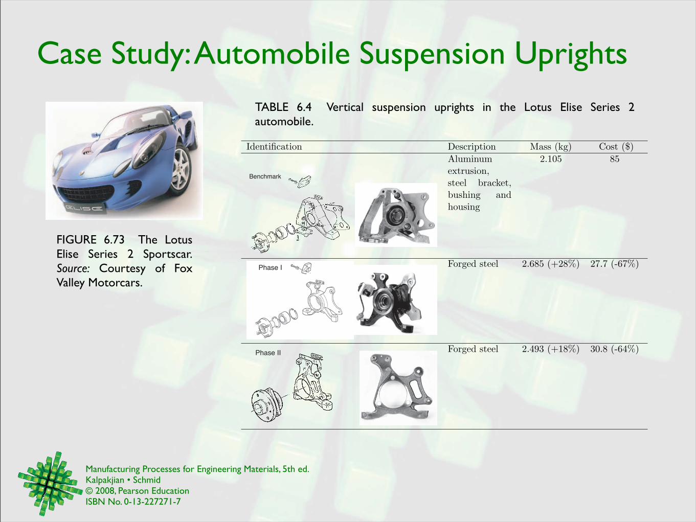
Case Study: Automobile Suspension Uprights
FIGURE 6.73 The Lotus Elise Series 2 Sportscar. Source: Courtesy of Fox Valley Motorcars.
Identification Description Mass (kg) Cost ($)Aluminumextrusion,steel bracket,bushing andhousing
2.105 85
Benchmark
Forged steel 2.685 (+28%) 27.7 (-67%)Phase I
Forged steel 2.493 (+18%) 30.8 (-64%)Phase II
TABLE 6.4 Vertical suspension uprights in the Lotus Elise Series 2 automobile.
Top Related