


Languages
Pages
Legal


PROJECT :
CLIENT : DESIGN BY :
JOB NO. : DATE : REVIEW BY :
8-Bolted Stiffened End Plate for SMF Based on AISC 341-10, 358-10, 360-10 & FEMA-350
INPUT DATA & DESIGN SUMMARYCOLUMN SECTION = > W14X211
A d62 15.7 0.98 15.80 1.56 338 2660 6.55 4.08 390
BEAM SECTION = > W21X62
A d18.3 21.0 0.40 8.24 0.62 127 1330 8.53 1.77 144
STRUCTURAL STEEL YIELD STRESS 50 ksi THE SMRF DESIGN IS ADEQUATE.
THE FACTOR GRAVITY LOAD ON THE BEAM 4.2 klf (Continuity column stiffeners 5/8 x 7
THE FACTOR AXIAL LOAD ON THE COLUMN 800 kips with 7/16" fillet weld to web & CP to flanges.BEAM LENGTH BETWEEN COL. CENTERS L = 30 ft A doubler plate is not required. )AVERAGE STORY HEIGHT OF ABOVE & BELOW h = 12 ftBOLTS 1 5/ 8 inGRADES (A325 or A490) A325
PLATE & SHIM 1 5/ 8 in
NUMBER COLUMNS 2(Top & Bot)
NUMBER BEAM 1(One Side Only)
ANALYSIS
6.00 in
3.75 in (AISC 358 Tab 6.1)
2.00 in (AISC 358 Tab 6.1)
= 22.17 in
4.62 in
10.88 in
< [Satisfactory]
CHECK BEAM LOCAL BUCKLING LIMITATIONS (AISC 341-10 Tab. D1.1)
6.70 < 7.22 [Satisfactory]
Where 29000 ksi
46.90 < 59.00 [Satisfactory]CHECK COLUMN LOCAL BUCKING LIMITATIONS (AISC 341-10 Tab. D1.1)
5.06 < 7.22 [Satisfactory]
11.61 <N/A
49.02
[Satisfactory] Where 0.9 3100 kips
CHECK BEAM - COLUMN RATIO REQUIREMENT (AISC 341-10 Sec. E3.4a)
2.59 > 1.00 [Satisfactory]
Where 2411 ft-kips
930 ft-kips, at center of column
204 ft-kips
726 ft-kips
1.1 (AISC 341-10 Tab. A3.1)
1.1 (FEMA Sec. 3.5.5.1)
CHECK BENDING MOMENT AT THE COLUMN FACE (FEMA Sec. 3.6.2.1.2)
= 858 ft-kips < 1205 ft-kips [Satisfactory]
Where 22.69 in 103 kips, (AISC 360-10, Tab. J3.1)
14.33 in 1.28
504.93424 kips
114.9 kips, (FEMA Sec. 3.6.2.1.2)
tw
bf
tf
Sx
Ix
rx
ry
Zx
tw
bf
tf
Sx
Ix
rx
ry
Zx
Fy =
wu =
Pu =
=
tp =
Nc =
Nb =
g =Max( bbf
- , tw + 3 ) =
Pb = 3 =
Pf = 1.5 =
Sh = d
c / 2 + t
p + 1" + (2P
f + P
b - 1") tan-1 30o
c = 2 Pf + t
bf =
bp = g + 3 =
bcf
bf / (2t
f ) = 0.3 (E
s / F
y)0.5 =
Es =
h / tw = 2.45 (E
s / F
y)0.5 =
bf / (2t
f ) = 0.3 (E
s / F
y)0.5 =
h / tw =2.45(E
s/F
y)0.5(1-0.93P
u/
cP
y) = , for P
u/
cP
y ≤ 0.125
0.77(Es/Fy)0.5(2.93-Pu/bPy) = , for Pu/cPy > 0.125
c = , P
y = F
yA =
Mpc
* / (Mpb
* ) =
Mpc
* = Nc Z
c (F
yc - P
u / A
g ) =
Mpb
* = Nb (M
hinge + M
v) =
Mv = V
hinge S
h = [2M
hinge /(L-2S
h)+w
u(L-2S
h)/2] S
h=
Mhinge
= Cpr
RyF
yb Z
b =
Ry =
Cpr
=
Mf = M
hinge + [2M
hinge / (L - 2S
h) + w
u(L - 2S
h)/2] (S
h - d
c /2)
3.4 Tub
(d0 + d
i ) =
d0 = db + P
f - 0.5 t
bf = T
b =
di = d
0 - c - P
b = A
bt = in2 / bolt
Ffu
= Mf / ( d
b - t
bf ) =
Tub
=
>[Satisfactory]
(0.00002305 Pf0.591 F
fu2.583 / (t
p0.895 d
bt1.909 t
bw0.327 b
p0.965) + T
b =

CHECK SHEAR CAPACITY AT THE COLUMN FACE (FEMA Sec. 3.6.2.1.3)
1.28 > 0.56 [Satisfactory]
Where 60.3 kips
36 ksi, (AISC 360-10, Tab. J3.2)
CHECK END PLATE THICKNESS (FEMA Sec. 3.6.2.1.4)
1.625 >
CHECK CONTINUITY PLATE REQUIREMENT (FEMA Sec. 3.6.2.1 & 3.3.3.1)
0.48 in <
0.60 in <(The continuity plates may not be required.)
Where 1.45 , (FEMA Sec. 3.6.2.1.5 )
0.43375
0.8308823 , (FEMA Sec. 3.6.2.1.5 )
0.62 in, USE
7 in < 9.93 in, (AISC 358-10 Eq 6.10-10)[Satisfactory]
1060.7 kips
Where 0.9 ,(AISC 360 E1) 11.38
K = 0.75 (AISC 360 E2)
175 20998.149 ksi (AISC 360 E3)
33 35.97 ksi (AISC 360 E3)
2.31 in 36 kips, plate yield stress
278.7 kips < [Satisfactory]
The best fillet weld size (AISC 360 Sec.J2.2b)
w = 7/16 in0.25 in
0.5625 in
[Satisfactory]
The required weld length between A36 continuity plates and column web (FEMA Fig 3-6)
= (0.625 x 8.4) x 36 / [(2) 0.75 (0.6x70)(0.707x7/16)] =
Where 8.4 <(Use complete joint penetration groove welds between continuity plates & column flanges.)
CHECK PANEL ZONE THICKNESS REQUIREMENT (AISC 341 Sec. E3.6e & FEMA Sec. 3.3.3.2)
0.80 in
0.80 in
Where 0.80
127
1330
930 ft-kips
0.35 in
0.98 in >not required.
Technical References: 1. AISC 341-10: "Seismic Provisions for Structural Steel Buildings", American Institute of Steel Construction, 2010. 2. AISC 358-10: "Prequalified Connections for Special and Intermediate Steel Moment Frames for Seismic Applications",
American Institute of Steel Construction, 2010. 3. AISC 360-10: "Specification for Structural Steel Buildings", American Institute of Steel Construction, 2010. 4. FEMA 350: "Recommended Seismic Design Criteria for New Steel Moment-frame Buildings.", SAC Joint Venture, 2000.
Ab = in2 [2 M
f / (L - d
c) + V
g ] / 6F
v =
Vg = w
u (L - d
c) / 2 =
Fv = F
nv =
tp = in
Max[ 0.00609 Pf0.9 g0.6 F
fu9 / (d
bt0.9 t
bw0.1 b
p0.7) , 0.00413 P
f0.25 g0.15 F
fu / (d
bt0.7 t
bw0.15 b
p0.3 )] =
tcf, reqD
= {m
Ffu
C3 / [0.9 F
yc (3.5 p
b + c)]}0.5 = t
cf, actual
tcw, reqD
= Mf
/ [( db - t
bf )( 6 k
c + 2 t
p + t
bf) F
yc] = t
cw, actual
Ca =
C3 = g / 2 - d
bt / 4 - k
c = in
m
= Ca (A
f / A
w )1 / 3 C3 / dbt
1 / 4 =
tst = t
bf for interior connection, or (t
bf /2) for exterior connection =
bst = 0.56 (E / F
yst )0.5 t
st =
cP
n,st =
cF
cr A
=
c = hst = dc - 2kc =
K hst / r
st < 200
I = tst (2b
st + t
wc) 3 / 12 = in4 F
e =
A = 2bsttst + 25(t
wc) 2 = in2 F
cr =
rst = ( I / A )0.5 = F
yst =
Pu,st
= Ryb
Fyb
bfb
tfb
= cP
n,st
> wMIN
=
< wMAX
=
Lw = 0.6t
stL
nstF
y / [(2) F
w (0.707 w)]
Lnet
= dc - 2(k
c + 1.5) =
tReqD
= MAX (t1, t
2) =
t1 = C
y M
c (h - d
b ) / [0.9 (0.6) F
yc R
yc d
c (d
b - t
fb) h] =
Cy = S
b / (C
pr Z
hing) =
Sb = 2I
b / d
b = in2
Ib = I
x = in4
Mc = M
pb* =
t2 = (d
z + w
z ) / 90 = (d
b -2t
st + d
c - 2k
c) / 90 =
Since twc
= tReqD
, a doubler plate is

PAGE : DESIGN BY : REVIEW BY :
k2.16
k1.12
THE SMRF DESIGN IS ADEQUATE.
with 7/16" fillet weld to web & CP to flanges.
[Satisfactory]
kips, (AISC 360-10, Tab. J3.1)

114.5 kips
(Cont'd)
[Satisfactory]
1.29517939[Satisfactory]
0.63 in, ( 5/8 in )
in, (AISC 358-10 Eq 6.10-10)
in
(AISC 360 E2) [Satisfactory]
ksi (AISC 360 E3)
ksi (AISC 360 E3)
kips, plate yield stress
4.42 in
[Satisfactory]
American Institute of Steel Construction, 2010.
in
2(Lnet
-0.5)
PROJECT :
CLIENT : DESIGN BY :
JOB NO. : DATE : REVIEW BY :
4-Bolted Stiffened End Plate for SMF Based on AISC 341-10, 358-10, 360-10 & FEMA-350
INPUT DATA & DESIGN SUMMARYCOLUMN SECTION = > W12X106
A d31.2 12.9 0.61 12.20 0.99 145 933 5.47 3.11 164
BEAM SECTION = > W18X50
A d14.7 18.0 0.36 7.50 0.57 88.9 800 7.38 1.65 101
STRUCTURAL STEEL YIELD STRESS 50 ksi THE SMRF DESIGN IS ADEQUATE.
THE FACTOR GRAVITY LOAD ON THE BEAM 4.2 klf (Continuity column stiffeners 5/8 x 6
THE FACTOR AXIAL LOAD ON THE COLUMN 800 kips with 5/16" fillet weld to web & CP to flanges.BEAM LENGTH BETWEEN COL. CENTERS L = 30 ft A doubler plate is required with thickness of 3/16 in. )AVERAGE STORY HEIGHT OF ABOVE & BELOW h = 12 ftBOLTS 1 3/ 4 inGRADES (A325 or A490) A325
PLATE & SHIM 3/ 4 in
NUMBER COLUMNS 2(Top & Bot)
NUMBER BEAM 1(One Side Only)
ANALYSIS
5.86 in
2.00 in (AISC 358 Tab 6.1)
= 13.40 in
4.57 in
11.11 in
< [Satisfactory]
CHECK BEAM LOCAL BUCKLING LIMITATIONS (AISC 341-10 Tab. D1.1)
6.58 < 7.22 [Satisfactory]
Where 29000 ksi
45.23 < 59.00 [Satisfactory]CHECK COLUMN LOCAL BUCKING LIMITATIONS (AISC 341-10 Tab. D1.1)
6.16 < 7.22 [Satisfactory]
15.93 <N/A
43.77
[Satisfactory] Where 0.9 1560 kips
CHECK BEAM - COLUMN RATIO REQUIREMENT (AISC 341-10 Sec. E3.4a)
1.08 > 1.00 [Satisfactory]
Where 666 ft-kips
615 ft-kips, at center of column
106 ft-kips
509 ft-kips
1.1 (AISC 341-10 Tab. A3.1)
1.1 (FEMA Sec. 3.5.5.1)
CHECK BENDING MOMENT AT THE COLUMN FACE (FEMA Sec. 3.6.1.1.2)
= 564 ft-kips < 719 ft-kips [Satisfactory]
Where 19.72 in 103 kips, (AISC 360-10, Tab. J3.1)
15.15 in 1.37
388.42813 kips
123.7 kips, (FEMA Sec. 3.6.1.1 & 3.6.2.1.2)
tw
bf
tf
Sx
Ix
rx
ry
Zx
tw
bf
tf
Sx
Ix
rx
ry
Zx
Fy =
wu =
Pu =
=
tp =
Nc =
Nb =
g =Max( bbf
- , tw + 3 ) =
Pf = 1.5 =
Sh = d
c / 2 + t
p + 1" + (2P
f - 1") tan-1 30o
c = 2 Pf + t
bf =
bp = g + 3 =
bcf
bf / (2t
f ) = 0.3 (E
s / F
y)0.5 =
Es =
h / tw = 2.45 (E
s / F
y)0.5 =
bf / (2t
f ) = 0.3 (E
s / F
y)0.5 =
h / tw =
2.45(Es/Fy)0.5(1-0.93Pu/cPy) = , for Pu/cPy ≤ 0.125
0.77(Es/F
y)0.5(2.93-P
u/
cP
y) = , for P
u/
cP
y > 0.125
c = , P
y = F
yA =
Mpc
* / (Mpb
* ) =
Mpc
* = Nc Z
c (F
yc - P
u / A
g ) =
Mpb
* = Nb (M
hinge + M
v) =
Mv = V
hinge S
h = [2M
hinge /(L-2S
h)+w
u(L-2S
h)/2] S
h=
Mhinge
= Cpr
RyF
yb Z
b =
Ry =
Cpr
=
Mf = M
hinge + [2M
hinge / (L - 2S
h) + w
u(L - 2S
h)/2] (S
h - d
c /2)
2 Tub
(d0 + d
i ) =
d0 = db + P
f - 0.5 t
bf = T
b =
di = d0 - c = A
bt = in2 / bolt
Ffu
= Mf / ( d
b - t
bf ) =
Tub
=

>[Satisfactory]
(0.00002305 Pf0.591 F
fu2.583 / (t
p0.895 d
bt1.909 t
bw0.327 b
p0.965) + T
b =
CHECK SHEAR CAPACITY AT THE COLUMN FACE (FEMA Sec. 3.6.1.1.3)
1.37 > 0.92 [Satisfactory]
Where 60.7 kips
36 ksi, (AISC 360-10, Tab. J3.2)
CHECK END PLATE THICKNESS (AISC 358-10 Eq 6.10-13)
0.75 > 0.41
Where 1258 in, (AISC 358-10 Tab. 6.3 Case 1)
36 ksi 1.0
CHECK CONTINUITY PLATE REQUIREMENT (AISC 358-10 Eq 6.10-13, FEMA Sec 3.3.3.1)
0.31 in <
Where 1595 in, (AISC 358-10 Tab. 6.5 Stiffened)
0.67 in >(The continuity plates required.)
0.57 in, USE
6 in < 9.93 in, (AISC 358-10 Eq 6.10-10)[Satisfactory]
544.2 kips
Where 0.9 ,(AISC 360 E1) 9.72
K = 0.75 (AISC 360 E2)
104 33474.401 ksi (AISC 360 E3)
17 35.98 ksi (AISC 360 E3)
2.49 in 36 kips, plate yield stress
235.1 kips < [Satisfactory]
The best fillet weld size (AISC 360 Sec.J2.2b)
w = 5/16 in0.1875 in
0.4375 in
[Satisfactory]
The required weld length between A36 continuity plates and column web (FEMA Fig 3-6)
= (0.625 x 6.7) x 36 / [(2) 0.75 (0.6x70)(0.707x5/16)] =
Where 6.7 <(Use complete joint penetration groove welds between continuity plates & column flanges.)
CHECK PANEL ZONE THICKNESS REQUIREMENT (AISC 341 Sec. E3.6e & FEMA Sec. 3.3.3.2)
0.77 in
0.77 in
Where 0.80
89
800
615 ft-kips
0.29 in
0.61 in <required with thickness of 3/16 in.
Technical References: 1. AISC 341-10: "Seismic Provisions for Structural Steel Buildings", American Institute of Steel Construction, 2010. 2. AISC 358-10: "Prequalified Connections for Special and Intermediate Steel Moment Frames for Seismic Applications",
American Institute of Steel Construction, 2010. 3. AISC 360-10: "Specification for Structural Steel Buildings", American Institute of Steel Construction, 2010. 4. FEMA 350: "Recommended Seismic Design Criteria for New Steel Moment-frame Buildings.", SAC Joint Venture, 2000.
Ab = in2 [2 M
f / (L - d
c) + V
g ] / 3F
v =
Vg = w
u (L - d
c) / 2 =
Fv = F
nv =
tp = in [1.11 M
f /
d F
yp Y
p)]0.5 = in
Yp =
Fyp
= d =
tcf, reqD
= [1.11 Mf /
d F
yc Y
c)]0.5 = t
cf, actual
Yc =
tcw, reqD
= Mf
/ [( db - t
bf )( 6 k
c + 2 t
p + t
bf) F
yc] = t
cw, actual
tst = t
bf for interior connection, or (t
bf /2) for exterior connection =
bst = 0.56 (E / F
yst )0.5 t
st =
cP
n,st =
cF
cr A =
c = h
st = d
c - 2k
c =
K hst / r
st < 200
I = tst (2b
st + t
wc) 3 / 12 = in4 F
e =
A = 2bsttst + 25(t
wc) 2 = in2 F
cr =
rst = ( I / A )0.5 = F
yst =
Pu,st
= Ryb
Fyb
bfb
tfb =
cP
n,st
> wMIN
=
< wMAX
=
Lw = 0.6t
stL
nstF
y / [(2) F
w (0.707 w)]
Lnet
= dc - 2(k
c + 1.5) =
tReqD
= MAX (t1, t
2) =
t1 = C
y M
c (h - d
b ) / [0.9 (0.6) F
yc R
yc d
c (d
b - t
fb) h] =
Cy = S
b / (C
pr Z
hing) =
Sb = 2I
b / d
b = in2
Ib = I
x = in4
Mc = M
pb* =
t2 = (d
z + w
z ) / 90 = (d
b -2t
st + d
c - 2k
c) / 90 =
Since twc
= tReqD
, a doubler plate is

PAGE : DESIGN BY : REVIEW BY :
k1.59
k0.97
THE SMRF DESIGN IS ADEQUATE.
with 5/16" fillet weld to web & CP to flanges.A doubler plate is required with thickness of 3/16 in. )
[Satisfactory]
kips, (AISC 360-10, Tab. J3.1)

113.3 kips

(Cont'd)
[Satisfactory]
[Satisfactory]
0.63 in, ( 5/8 in )
in, (AISC 358-10 Eq 6.10-10)
in
(AISC 360 E2) [Satisfactory]
ksi (AISC 360 E3)
ksi (AISC 360 E3)
kips, plate yield stress
4.61 in
[Satisfactory]
American Institute of Steel Construction, 2010.
2(Lnet
-0.5)
PROJECT :
CLIENT : DESIGN BY :
JOB NO. : DATE : REVIEW BY :
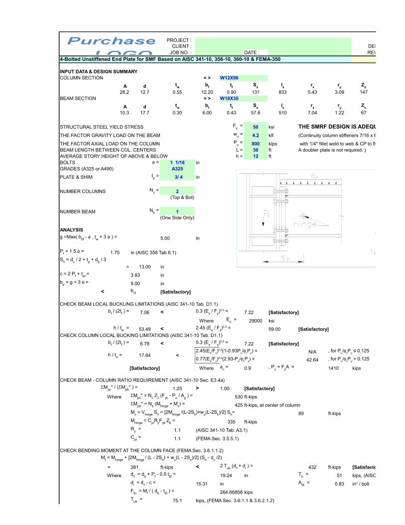
4-Bolted Unstiffened End Plate for SMF Based on AISC 341-10, 358-10, 360-10 & FEMA-350
INPUT DATA & DESIGN SUMMARYCOLUMN SECTION = > W12X96
A d28.2 12.7 0.55 12.20 0.90 131 833 5.43 3.09 147
BEAM SECTION = > W18X35
A d10.3 17.7 0.30 6.00 0.43 57.6 510 7.04 1.22 67
STRUCTURAL STEEL YIELD STRESS 50 ksi THE SMRF DESIGN IS ADEQUATE.
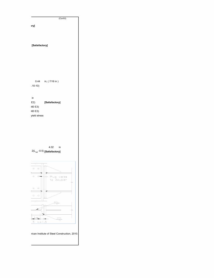
THE FACTOR GRAVITY LOAD ON THE BEAM 4.2 klf (Continuity column stiffeners 7/16 x 6
THE FACTOR AXIAL LOAD ON THE COLUMN 800 kips with 1/4" fillet weld to web & CP to flanges.BEAM LENGTH BETWEEN COL. CENTERS L = 30 ft A doubler plate is not required. )AVERAGE STORY HEIGHT OF ABOVE & BELOW h = 12 ftBOLTS 1 1/16 inGRADES (A325 or A490) A325
PLATE & SHIM 3/ 4 in
NUMBER COLUMNS 2(Top & Bot)
NUMBER BEAM 1(One Side Only)
ANALYSIS
5.00 in
1.75 in (AISC 358 Tab 6.1)
= 13.00 in
3.93 in
9.00 in
< [Satisfactory]
CHECK BEAM LOCAL BUCKLING LIMITATIONS (AISC 341-10 Tab. D1.1)
7.06 < 7.22 [Satisfactory]
Where 29000 ksi
53.49 < 59.00 [Satisfactory]CHECK COLUMN LOCAL BUCKING LIMITATIONS (AISC 341-10 Tab. D1.1)
6.78 < 7.22 [Satisfactory]
17.64 <N/A
42.64
[Satisfactory] Where 0.9 1410 kips
CHECK BEAM - COLUMN RATIO REQUIREMENT (AISC 341-10 Sec. E3.4a)
1.25 > 1.00 [Satisfactory]
Where 530 ft-kips
425 ft-kips, at center of column
89 ft-kips
335 ft-kips
1.1 (AISC 341-10 Tab. A3.1)
1.1 (FEMA Sec. 3.5.5.1)
CHECK BENDING MOMENT AT THE COLUMN FACE (FEMA Sec. 3.6.1.1.2)
= 381 ft-kips < 432 ft-kips [Satisfactory]
Where 19.24 in 51 kips, (AISC 360-10, Tab. J3.1)
15.31 in 0.83
264.66858 kips
75.1 kips, (FEMA Sec. 3.6.1.1 & 3.6.2.1.2)
tw
bf
tf
Sx
Ix
rx
ry
Zx
tw
bf
tf
Sx
Ix
rx
ry
Zx
Fy =
wu =
Pu =
=
tp =
Nc =
Nb =
g =Max( bbf
- , tw + 3 ) =
Pf = 1.5 =
Sh = d
c / 2 + t
p + d
b / 3
c = 2 Pf + t
bf =
bp = g + 3 =
bcf
bf / (2t
f ) = 0.3 (E
s / F
y)0.5 =
Es =
h / tw = 2.45 (E
s / F
y)0.5 =
bf / (2t
f ) = 0.3 (E
s / F
y)0.5 =
h / tw =
2.45(Es/Fy)0.5(1-0.93Pu/cPy) = , for Pu/cPy ≤ 0.125
0.77(Es/F
y)0.5(2.93-P
u/
cP
y) = , for P
u/
cP
y > 0.125
c = , P
y = F
yA =
Mpc
* / (Mpb
* ) =
Mpc
* = Nc Z
c (F
yc - P
u / A
g ) =
Mpb
* = Nb (M
hinge + M
v) =
Mv = V
hinge S
h = [2M
hinge /(L-2S
h)+w
u(L-2S
h)/2] S
h=
Mhinge
= Cpr
RyF
yb Z
b =
Ry =
Cpr
=
Mf = M
hinge + [2M
hinge / (L - 2S
h) + w
u(L - 2S
h)/2] (S
h - d
c /2)
2 Tub
(d0 + d
i ) =
d0 = db + P
f - 0.5 t
bf = T
b =
di = d0 - c = A
bt = in2 / bolt
Ffu
= Mf / ( d
b - t
bf ) =
Tub
=

>[Satisfactory]
(0.00002305 Pf0.591 F
fu2.583 / (t
p0.895 d
bt1.909 t
bw0.327 b
p0.965) + T
b =

CHECK SHEAR CAPACITY AT THE COLUMN FACE (FEMA Sec. 3.6.1.1.3)
0.83 > 0.81 [Satisfactory]
Where 60.8 kips
36 ksi, (AISC 360-10, Tab. J3.2)
CHECK END PLATE THICKNESS (AISC 358-10 Eq 6.10-13)
0.75 > 0.40
Where 864 in, (AISC 358-10 Tab. 6.2)
36 ksi 1.0
CHECK CONTINUITY PLATE REQUIREMENT (AISC 358-10 Eq 6.10-13, FEMA Sec 3.3.3.1)
0.41 in <
Where 594 in, (AISC 358-10 Tab. 6.5 Unsiffened)
0.48 in <(The continuity plates may not be required.)
0.43 in, USE
6 in < 6.95 in, (AISC 358-10 Eq 6.10-10)[Satisfactory]
414.9 kips
Where 0.9 ,(AISC 360 E1) 9.7
K = 0.75 (AISC 360 E2)
72 30417.664 ksi (AISC 360 E3)
13 35.98 ksi (AISC 360 E3)
2.37 in 36 kips, plate yield stress
140.3 kips < [Satisfactory]
The best fillet weld size (AISC 360 Sec.J2.2b)
w = 1/4 in0.1875 in
0.3125 in
[Satisfactory]
The required weld length between A36 continuity plates and column web (FEMA Fig 3-6)
= (0.4375 x 6.7) x 36 / [(2) 0.75 (0.6x70)(0.707x1/4)] =
Where 6.7 <(Use complete joint penetration groove welds between continuity plates & column flanges.)
CHECK PANEL ZONE THICKNESS REQUIREMENT (AISC 341 Sec. E3.6e & FEMA Sec. 3.3.3.2)
0.54 in
0.54 in
Where 0.79
58
510
425 ft-kips
0.29 in
0.55 in >not required.
Technical References: 1. AISC 341-10: "Seismic Provisions for Structural Steel Buildings", American Institute of Steel Construction, 2010. 2. AISC 358-10: "Prequalified Connections for Special and Intermediate Steel Moment Frames for Seismic Applications",
American Institute of Steel Construction, 2010. 3. AISC 360-10: "Specification for Structural Steel Buildings", American Institute of Steel Construction, 2010. 4. FEMA 350: "Recommended Seismic Design Criteria for New Steel Moment-frame Buildings.", SAC Joint Venture, 2000.
Ab = in2 [2 M
f / (L - d
c) + V
g ] / 3F
v =
Vg = w
u (L - d
c) / 2 =
Fv = F
nv =
tp = in [1.11 M
f /
d F
yp Y
p)]0.5 = in
Yp =
Fyp
= d =
tcf, reqD
= [1.11 Mf /
d F
yc Y
c)]0.5 = t
cf, actual
Yc =
tcw, reqD
= Mf
/ [( db - t
bf )( 6 k
c + 2 t
p + t
bf) F
yc] = t
cw, actual
tst = t
bf for interior connection, or (t
bf /2) for exterior connection =
bst = 0.56 (E / F
yst )0.5 t
st =
cP
n,st =
cF
cr A =
c = h
st = d
c - 2k
c =
K hst / r
st < 200
I = tst (2b
st + t
wc) 3 / 12 = in4 F
e =
A = 2bsttst + 25(t
wc) 2 = in2 F
cr =
rst = ( I / A )0.5 = F
yst =
Pu,st
= Ryb
Fyb
bfb
tfb =
cP
n,st
> wMIN
=
< wMAX
=
Lw = 0.6t
stL
nstF
y / [(2) F
w (0.707 w)]
Lnet
= dc - 2(k
c + 1.5) =
tReqD
= MAX (t1, t
2) =
t1 = C
y M
c (h - d
b ) / [0.9 (0.6) F
yc R
yc d
c (d
b - t
fb) h] =
Cy = S
b / (C
pr Z
hing) =
Sb = 2I
b / d
b = in2
Ib = I
x = in4
Mc = M
pb* =
t2 = (d
z + w
z ) / 90 = (d
b -2t
st + d
c - 2k
c) / 90 =
Since twc
= tReqD
, a doubler plate is

PAGE : DESIGN BY : REVIEW BY :
k1.50
k0.83
THE SMRF DESIGN IS ADEQUATE.
(Continuity column stiffeners 7/16 x 6
with 1/4" fillet weld to web & CP to flanges.
[Satisfactory]
kips, (AISC 360-10, Tab. J3.1)

62.9 kips
(Cont'd)
[Satisfactory]
[Satisfactory]
0.44 in, ( 7/16 in )
in, (AISC 358-10 Eq 6.10-10)
in
(AISC 360 E2) [Satisfactory]
ksi (AISC 360 E3)
ksi (AISC 360 E3)
kips, plate yield stress
4.02 in
[Satisfactory]
American Institute of Steel Construction, 2010.
2(Lnet
-0.5)
Top Related