


Languages
Pages
Legal


Brisbane City Council Bicycle Signage Manual
SEPTEMBER 2014
Part 2 Directional signage for local facilities
LOCAL FACILITY

GRAPHIC STANDARDS
Section D Graphic standards for local facility signage
56Brisbane City Council Bicycle Signage Manual • September 2014
D1.1
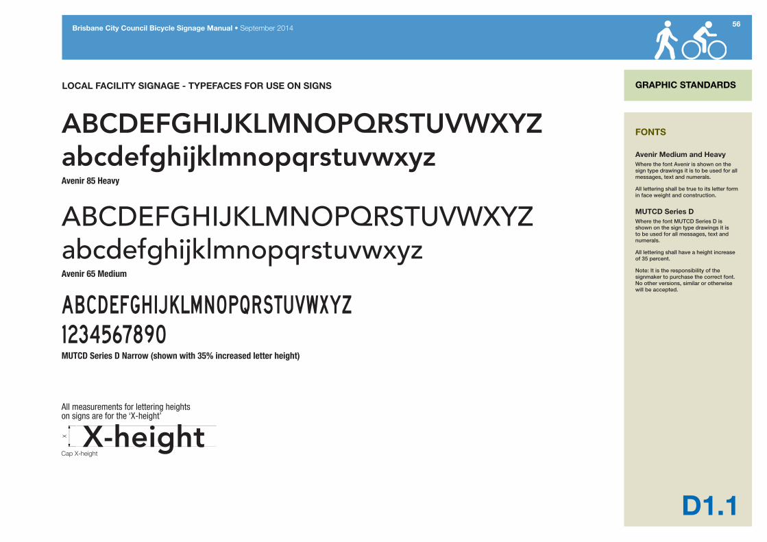
LOCAL FACILITY SIGNAGE - TYPEFACES FOR USE ON SIGNS
ABCDEFGHIJKLMNOPQRSTUVWXYZabcdefghijklmnopqrstuvwxyzAvenir 85 Heavy
ABCDEFGHIJKLMNOPQRSTUVWXYZabcdefghijklmnopqrstuvwxyzAvenir 65 Medium
MUTCD Series D Narrow (shown with 35% increased letter height)
All measurements for lettering heights on signs are for the ‘X-height’
GRAPHIC STANDARDS
FONTS
Avenir Medium and HeavyWhere the font Avenir is shown on the sign type drawings it is to be used for all messages, text and numerals.
All lettering shall be true to its letter form in face weight and construction.
MUTCD Series DWhere the font MUTCD Series D is shown on the sign type drawings it is to be used for all messages, text and numerals.
All lettering shall have a height increase of 35 percent.
Note: It is the responsibility of the signmaker to purchase the correct font. No other versions, similar or otherwise will be accepted.

57Brisbane City Council Bicycle Signage Manual • September 2014
GRAPHIC STANDARDS
D1.2
LOCAL FACILITY SIGNAGE - COLOURS USED ON SIGNS AND PICTOGRAMS
AS2700 B51 Periwinkle BluePantone 293RGB 0, 103, 177
PRIMARY SIGN COLOURS
PICTOGRAM/SYMBOL COLOURS
AS2700 G37 Beanstalk GreenPantone 355RGB 0, 169, 79
White symbol on blueAS2700 B51 Blue
Yellow symbol AS2700 Y26 Yellow on AS2700 B51 Blue
White symbol on AS2700 G37 Green
White symbol on AS2700 R13 Red
White symbol on AS2700 B51 Blue
AS2700 Y26 Homebush Yellow Pantone 116RGB 255, 210, 0
COLOURS
Colours as specified to be used for all parts and faces as noted on the sign type drawings.
58Brisbane City Council Bicycle Signage Manual • September 2014
GRAPHIC STANDARDS
D1.3
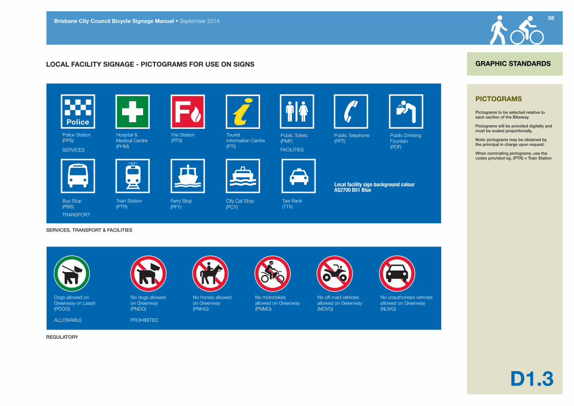
LOCAL FACILITY SIGNAGE - PICTOGRAMS FOR USE ON SIGNS
Local facility sign background colour AS2700 B51 Blue
PICTOGRAMS
Pictograms to be selected relative to each section of the Bikeway.
Pictograms will be provided digitally and must be scaled proportionally.
Note: pictograms may be obtained by the principal in charge upon request.
When nominating pictograms, use the codes provided eg. (PTR) = Train Station

59Brisbane City Council Bicycle Signage Manual • September 2014
GRAPHIC STANDARDS
D1.4
LOCAL FACILITY SIGNAGE - ARROWS FOR USE ON SIGNS
Arrow sizing for all on-road cycle network directional signage is the width of the arrow head as indicated in the sample left.Ar
row
siz
esgi
ven
in m
m ARROWS
The arrow artwork as shown is to be used for all directional signs.
The artwork will be provided digitally and must be scaled proportionately.
No other versions, similar or otherwise will be accepted.

60Brisbane City Council Bicycle Signage Manual • September 2014
GRAPHIC STANDARDS
D1.5
LOCAL FACILITY SIGNAGE - MAPPING FOR USE ON IF1 SIGNS
TYPICAL BRISWAY MAP MODIFIED FOR USE ON IF SIGNS
INFORMATION MAPS
The map shall be produced on a street directory background. All existing cycling and walking routes should be shown on the map. Map should include a legend and a “You are here” indicator.
The artwork will be provided digitally and must be scaled proportionately.
No other versions, similar or otherwise will be accepted.

LOCAL FACILITY
Section E Local facility signage design details

62Brisbane City Council Bicycle Signage Manual • September 2014
E1.0
INFORMATION MAP SIGN LOCAL FACILITY
PURPOSELocal facility information map signs show bicycle riders and pedestrians existing bicycle routes and walking paths in relation to the location of the map. The map should include all existing bikeways and paths with exits to the adjacent street system clearly marked. Surrounding features may include but are not limited to the following:• road network• public transport stations• parks, sporting or recreation grounds• local centres• major destinations such as shopping
centres and employment nodes• educational facilities• police stations• hospitals• public libraries• places of worship• scout/ community halls• public toilets• bicycle parking• waterways, water reservoirs, and• significant natural landmarks
Maps are produced at an appropriate scale to ensure the bikeway/shared path and surrounding features are easily identifiable. Significant attractors that exist outside the map area are marked with text and an arrow indicating the direction of the facility or destination (e.g. CBD 4km).
LOCATIONInformation map signs are usually placed at path junctions or at path locations linking to a high number of local trip attractors such as shopping centres, public transport stations, educational facilities and recreation centres.
There are two types of IF1 information map signs: The IF1-1 sign is designed to be mounted adjacent to a named bikeway; the IF1-2 sign is designed for mounting adjacent to paths in a parkland setting where the path is not a named facility.
IF1 map signs are not designed to be used for on-road sections of the BCC Bikeway Network. The MBP map board detailed on Section B6 of this manual is designed for use with on-road bikeways.
Information Map signs (IF-1 and IF-2) are installed at least 1.0m from the path edge to ensure there is sufficient space to move off the path to read the sign and not create a hazard for other path users. On high-use paths it is preferable to locate the map sign in a paved viewing bay separate from the main path. Refer to Sheets E1.5 and E1.6 for details.
To indicate desired/safe rest stops along bikeways, the location of signage, where appropriate, is co-located with other bikeway infrastructure such as seats, lights, racks, shelters etc. The location of signs in lit areas is recommended to extend the functional hours the signs are usable.
GROUND TRUTHINGInformation maps are positioned where the pathway user can easily translate the information from the map to the surrounding environment. Map signs should be located to allow path users to view the map when facing in a northerly direction to facilitate easy map orientation.
The position of the information map for maximum visibility also provides casual surveillance from passers-by which may discourage vandalism to the sign.
Ensure there is enough space to install the sign next to the bikeway so there is a minimum 1.0m clearance from the path.
SIGN TYPE IF1-1 / IF1-2
INFORMATION MAP SIGN
E1.1Construction Details
E1.2Graphic Details (Map on bikeway)
E1.3Graphic Details (Map in park – no bikeway)
E1.4Map Cropping Details

63Brisbane City Council Bicycle Signage Manual • September 2014
LOCAL FACILITY
E1.1
IF1-1 & IF1-2 INFORMATION MAP SIGNS GENERAL LAYOUT
IF1-1 MAP ON BIKEWAY IF1-2 MAP IN PARK (NO BIKEWAY)
WEIV EDIS WEIV TNORF WEIV EDIS WEIV TNORF
600
600
1
2
3
4
5
800
800
1000
1770
1680
914
SIGN TYPE IF1-1 / IF1-2
INFORMATION MAP SIGN
Construction Details 1. 1.6mm aluminium type 5251,
tempered H38 as specified in Australian Standards 1734, sign panel with 5mm radius corners and digitally printed graphics.
2. Type 1 aluminium stiffener rail centred widthways 100mm less of sheet width with mounted to galvanised post using straps and buckle.
3. Sign panel to type 1 aluminium stiffener rails using self-piercing riveting system (eg. Henrob).
4. Mounting and construction to BCC Reference specification S154.
Graphic DetailsDigital printed graphics using full solvent inks onto 600 x 1000mm White Cast Vinyl sheeted with anti-graffiti overlay film NI-EF 40801-12-45 or equivalent.IF1-1 (Map on bikeway) - Refer to page E1.2IF1-2 (Map in park – no bikeway) - Refer to page E1.3
64Brisbane City Council Bicycle Signage Manual • September 2014
LOCAL FACILITY
E1.2
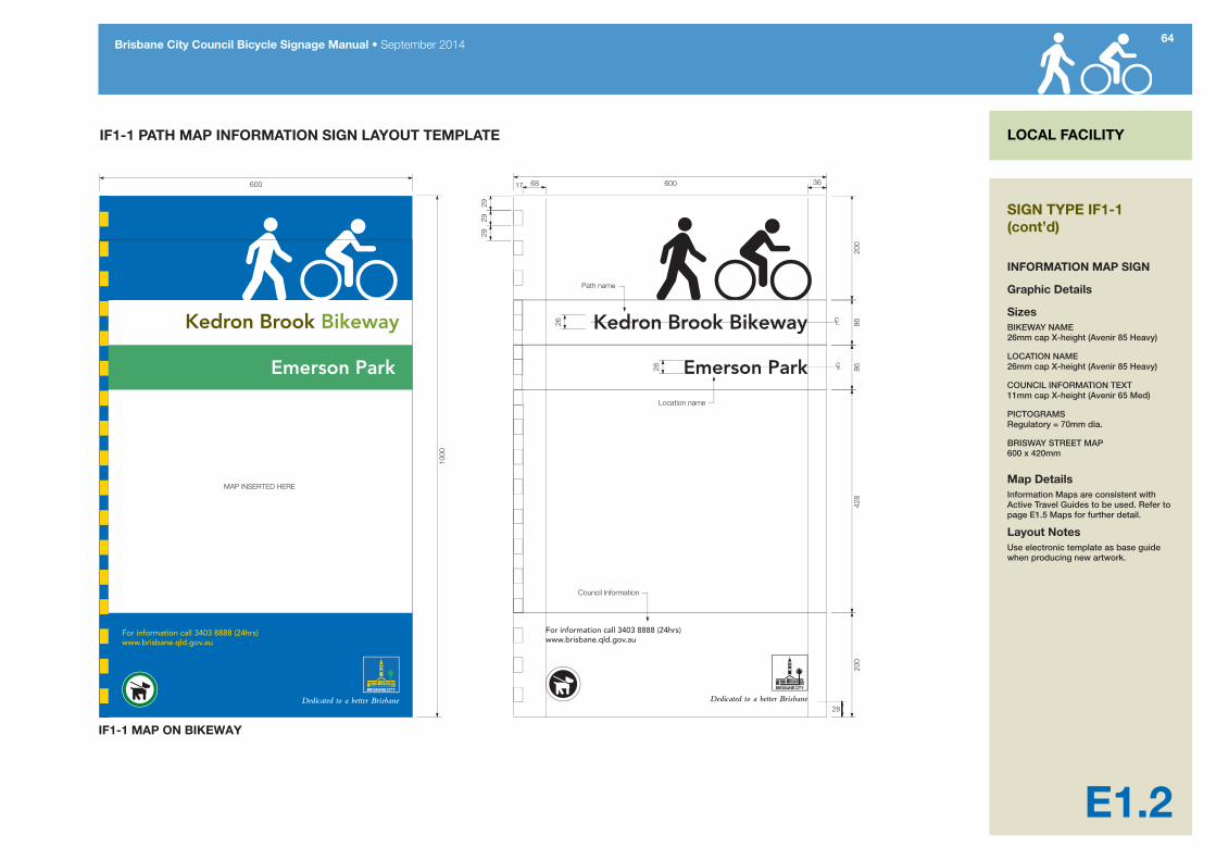
IF1-1 PATH MAP INFORMATION SIGN LAYOUT TEMPLATE
Path name
MAP INSERTED HERE
Kedron Brook Bikeway Kedron Brook Bikeway
IF1-1 MAP ON BIKEWAY
17
28
SIGN TYPE IF1-1 (cont’d)
INFORMATION MAP SIGN
Graphic Details
SizesBIKEWAY NAME 26mm cap X-height (Avenir 85 Heavy)
LOCATION NAME 26mm cap X-height (Avenir 85 Heavy)
COUNCIL INFORMATION TEXT 11mm cap X-height (Avenir 65 Med)
PICTOGRAMS Regulatory = 70mm dia.
BRISWAY STREET MAP 600 x 420mm
Map DetailsInformation Maps are consistent with Active Travel Guides to be used. Refer to page E1.5 Maps for further detail.
Layout NotesUse electronic template as base guide when producing new artwork.
65Brisbane City Council Bicycle Signage Manual • September 2014
LOCAL FACILITY
E1.3
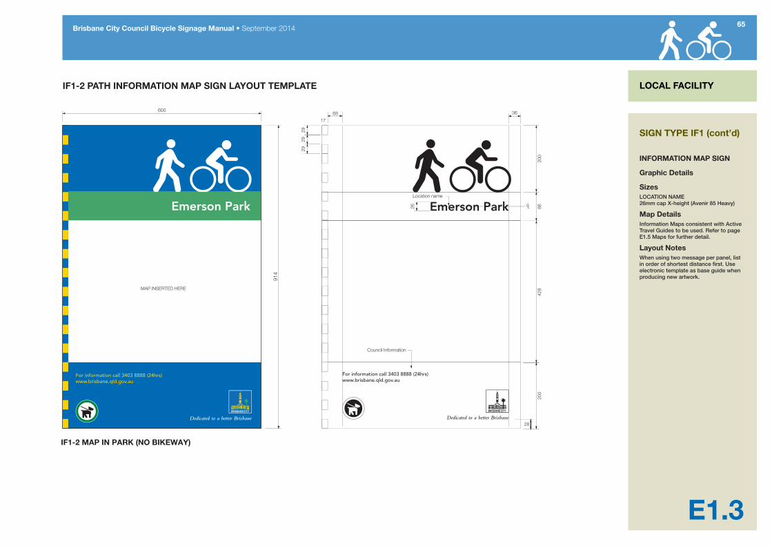
IF1-2 PATH INFORMATION MAP SIGN LAYOUT TEMPLATE
MAP INSERTED HERE
IF1-2 MAP IN PARK (NO BIKEWAY)
914
17
28
SIGN TYPE IF1 (cont’d)
INFORMATION MAP SIGN
Graphic Details
SizesLOCATION NAME 26mm cap X-height (Avenir 85 Heavy)
Map DetailsInformation Maps consistent with Active Travel Guides to be used. Refer to page E1.5 Maps for further detail.
Layout NotesWhen using two message per panel, list in order of shortest distance first. Use electronic template as base guide when producing new artwork.

66Brisbane City Council Bicycle Signage Manual • September 2014
LOCAL FACILITY
E1.4
IF1-1 & IF1-2 MAP INFORMATION SIGNS MAP CROPPING DETAILS
ORIGINAL BRISWAY MAP AS SUPPLIED BY COUNCIL
BRISWAY MAP CROPPED FOR IF1 SIGN TYPICAL IF1-1 SIGN
Crop zone600
600
1000
428
SIGN TYPE IF1 (cont’d)
INFORMATION MAP SIGN
Map Cropping NotesMap cropped to IF1-1 and IF1-2 sign proportion (always crop to height).
“You Are Here” to be approximately centred within map. Always to include Legend.
The map should always be orientated to the way the user is facing.

67Brisbane City Council Bicycle Signage Manual • September 2014
LOCAL FACILITY
E1.5
IF1 INFORMATION MAP BOARDS SITING DETAILS FOR OFF-ROAD USE
Ked
ron B
rook B
ikeway
Ked
ron
Bro
ok B
ikew
ay
IF1-1 OR IF1-2 Information Map Sign
3.0m
min
50m
5.0m min
45º
50mIF2-L sign
IF2-R sign
Parklands
Parklands
Figure A: Information Map Sign Viewing Bay for off-road pathThe diagram below shows recommended layout for high-use path map sign viewing bay.
Figure B: Information Map Sign Viewing Bay exampleThis photograph shows a map sign viewing bay constructed adjacent to a high-use shared path with kerbed path and additional landscaping. Roma Street Parklands/Normanby Pedestrian Cycle Link.
SIGN TYPE IF-1 (cont’d)
INFORMATION MAP SIGN
Map Sign Siting NotesIF1 signs are always mounted off the path in adjacent parklands with sufficient surrounding space to permit comfortable viewing of the map without obstructing the normal flow of pedestrians or cyclists using the path.
The viewing area surrounding the map sign should be paved to minimise erosion as detailed in Figure A.
On paths with high usage volumes mount IF2-L and IF2-R signs on each approach direction 50metres in advance of the map bay.

68Brisbane City Council Bicycle Signage Manual • September 2014
LOCAL FACILITY
E1.6
IF2 INFORMATION MAP VIEWING BAY ADVANCE DIRECTION SIGN GENERAL LAYOUT
Kedron Brook Bikeway
Kedron Brook Bikeway
45mm
120m
m75
mm65
mm
45mm
80mm
65mm
IF2-L (left arrow) Advance Direction Sign artwork templateFor use with path information map viewing bay
IF2-R (right arrow) Advance Direction Sign artwork templateFor use with path information map viewing bay
45mm
120m
m75
mm65
mm
45mm
80mm
65mm
IF2-L General sign layout
IF2-R General sign layout
SIGN TYPE IF2
INFORMATION MAP SIGN VIEWING BAY ADVANCE DIRECTION SIGN GENERAL DETAILS
Construction Details1. 1.6mm aluminium type 5251,
tempered H38 as specified in Australian Standards 1734, sign panel with 5mm radius corners and digitally printed graphics.
2. Type 1 aluminium stiffener rail centred widthways 100mm less of sheet width with mounted to galvanised post using straps and buckle.
3. Sign panel to type 1 aluminium stiffener rails using self-piercing riveting system (eg. Henrob).
4. Mounting and construction to BCC Reference specification S154.
Graphic DetailsDigital printed graphics in using full solvent inks onto white Class 1 retroreflective material sheeted with anti-graffiti overlay film NI-EF 40801-12-45 or equivalent.
SizesBIKEWAY NAME 26mm cap X-height (Avenir 85 Heavy)
MESSAGE 26mm cap X-height (Avenir 85 Heavy)
PICTOGRAM PTI = 65 x 65mm
ARROW 80mm

69Brisbane City Council Bicycle Signage Manual • September 2014
E2.0
LOCAL FACILITY FINGERBOARDS LOCAL FACILITY
PURPOSELocal facility fingerboards are used on paths and bikeways to indicate local nearby local facilities (such as toilets, water park amenities) and community facilities within walking distance (up to 800m) of the path. Local Facility fingerboards are also used to mark all linking paths which connect the main path to the surrounding street system.
DR1-1 fingerboards are used to indicate the direction of travel and the approximate walking/cycling distance for a maximum of two destinations per sign blade.
DR1-2 fingerboards are used to mark named paths/bikeways and to indicate the direction to these paths/bikeways from the surrounding streets system.
LOCATIONDR1 fingerboards are placed at all path junctions where branching paths lead off to close-by community facilities or park amenities such as local shops, toilets, water, schools and community centres. On routes to local facilities greater than 1km, a local route using FBL fingerboards and RML markers should be used instead.
DR1 fingerboards are used in conjunction with ID2 linked street pavement markers to indicate all connections between the main path and the local street system (eg To Gympie Rd). The consistent and comprehensive installation of DR1 signs and linked street pavement markings greatly improves the personal safety
and security of path users by providing them with ample location information essential for navigation and in case of emergency.
DR1-2 signs are used to identify named bikeways (eg Kedron Brook Bikeway) and are located along to path as well as at the start of paths feeding the bikeway.
All posts are to be set a minimum of 500mm from the path edge.
GROUND TRUTHINGFingerboards need to be positioned in a way that minimises confusion at path junctions, particularly where there are multiple junctions.
Where applicable, fingerboards should direct pathway users to the most appropriate entrance to the identified location (e.g. main school entrance).
Fingerboards located near roads must be positioned in a way that minimises confusion with road signs and names.
SIGN TYPE DR1
FINGERBOARD DIRECTIONAL SIGN
E2.1Construction Details
E2.2Graphic Details (Standard message fingerboard)
E2.3Graphic Details (Standard message fingerboard)
E2.4Graphic Details (Bikeway Name fingerboard)
70Brisbane City Council Bicycle Signage Manual • September 2014
LOCAL FACILITY
E2.1
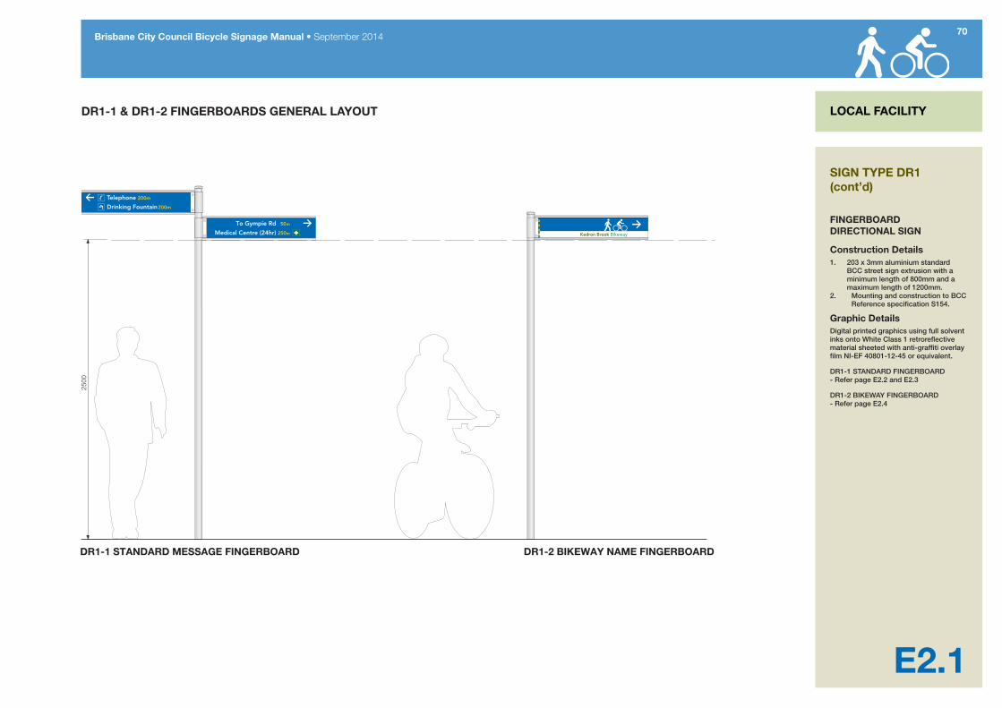
DR1-1 & DR1-2 FINGERBOARDS GENERAL LAYOUT
To Gympie Rd 50m
Medical Centre (24hr) 250m
Telephone 200m
Drinking Fountain 200m
Kedron Brook Bikeway
DR1-1 STANDARD MESSAGE FINGERBOARD DR1-2 BIKEWAY NAME FINGERBOARD
2500
SIGN TYPE DR1 (cont’d)
FINGERBOARD DIRECTIONAL SIGN
Construction Details1. 203 x 3mm aluminium standard
BCC street sign extrusion with a minimum length of 800mm and a maximum length of 1200mm.
2. Mounting and construction to BCC Reference specification S154.
Graphic DetailsDigital printed graphics using full solvent inks onto White Class 1 retroreflective material sheeted with anti-graffiti overlay film NI-EF 40801-12-45 or equivalent.
DR1-1 STANDARD FINGERBOARD - Refer page E2.2 and E2.3
DR1-2 BIKEWAY FINGERBOARD - Refer page E2.4

DR1-1 Sign Layout - reverse sideDR1-1 Sign Layout - front side
Mou
ntin
g en
d
Drinking Fountain 150m
Shopping Centre via Milford St 200m
Police Station 50m
Kedron Park Primary School 250m
To Gympie Rd 50m
Medical Centre (24hr) 1.1km
Toilets 30m
Telephone 100m
50m
Medical Centre (24hr) 250m
Telephone 50m
250m MTe
Mou
ntin
g en
d
71Brisbane City Council Bicycle Signage Manual • September 2014
LOCAL FACILITY
E2.2
DR1-1 FINGERBOARD LAYOUT VARIATIONS
Sign content notes1. Fingerboards are double sided. Arrows on the reverse side always point
away from the sign mount and indicate direction of travel.2. The closest destinations are listed to the top of the sign. 3. Distance numerals and pictograms (when used) are located between the
direction arrow and the destination distance. The direction arrow always points outwards from the sign mounting towards the direction of travel.
4. DR1-1 Local facility �ngerboards are seldom used to indicate distances greater than 1km. Destinations above 1km remote from the path should use FBL Local Destination �ngerboards and RML markers to mark the route. See Section B8 of this manual.
5. Where distances above 1km are used, these are shown to the nearest 100 metres in standard decimal form followed by the abbreviation ‘km’ (no space in between) eg 1.7km and 1.9km.
6. Distances less than one kilometre are shown in metres (rounded to the nearest 50 metres eg: 350m). When listed on signs the numerals and the ‘m’ abbreviation (no space in between) are aligned right with other destination numerals.
7. Distances below 50m are not shown.8. Distance numerals are aligned on the decimal point as per FBP signs. 9. Distance numerals one kilometre and above are the same point size as
destination names (36mm X-height). Numerals for distances less than one kilometre are shown in metres and have an X-height of 30mm.
10. Maximum length of �ngerboard is 1200mm subject to lettering content.
SIGN TYPE DR1-1
FINGERBOARD DIRECTIONAL SIGN
Graphic Details
SizesDESTINATIONS 36mm cap X-height (Avenir 85 Heavy)
DISTANCE 30mm cap X-height (Avenir 85 Heavy)
METRES 18mm lower case x-height (Avenir 85 Heavy)
PICTOGRAMS 58 X 58mm
ARROWS 70mm
Layout NotesLayout is the same for all four sizes of finger blades.
When no pictograms are used on the sign panel, the message must align to the pictogram alignment (as shown).
Use Template - Typical Graphic Detail only as the electronic template for base guide when producing new artwork.
72Brisbane City Council Bicycle Signage Manual • September 2014
LOCAL FACILITY
E2.3
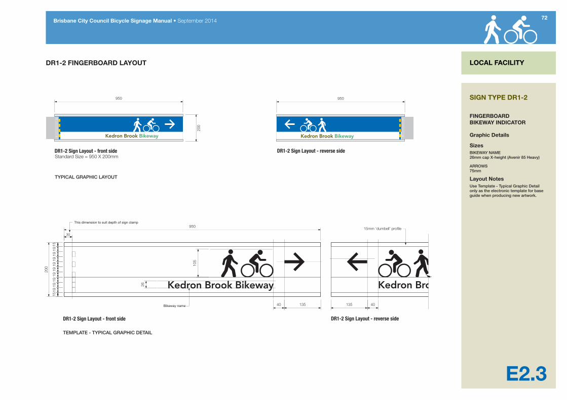
DR1-2 FINGERBOARD LAYOUT
Bikeway name
This dimension to suit depth of sign clamp
Kedron Brook Bikeway
Kedron Brook Bikeway
Kedron Brook Bikeway
DR1-2 Sign Layout - reverse sideDR1-2 Sign Layout - front side
DR1-2 Sign Layout - reverse sideDR1-2 Sign Layout - front side
SIGN TYPE DR1-2
FINGERBOARD BIKEWAY INDICATOR
Graphic Details
SizesBIKEWAY NAME 26mm cap X-height (Avenir 85 Heavy)
ARROWS 75mm
Layout NotesUse Template - Typical Graphic Detail only as the electronic template for base guide when producing new artwork.

73Brisbane City Council Bicycle Signage Manual • September 2014
E3.0
LOCAL FACILITY REASSURANCE SIGN LOCAL FACILITY
PURPOSEThis sign is used to provide distance information (km to important places and facilities) that can be reached along the bikeway/shared path. These signs are only used on lengthy or remote paths which are no part of the bicycle network.
Four to five key destinations per sign are identified and placed incrementally.
Messages on signs could include prominent cross-roads/streets, parks and community facilities (e.g. Kalinga Park, Sandgate Road, Stafford City Shopping Centre).
It is also useful to identify the distance to termination of longer paths. This assists users to judge their travel progress.
LOCATIONDistance guide signs are installed near intersections with access paths or near areas of high use (e.g. parks, playgrounds etc).
All posts are to be set a minimum of 500mm from the path edge.
GROUND TRUTHINGWhere possible, avoid locating an information map and distance guide sign in the direct vicinity of each other.
SIGN TYPE DR2
REASSURANCE DIRECTION SIGNE3.1 Construction Details
E3.2 Graphic Details

74Brisbane City Council Bicycle Signage Manual • September 2014
LOCAL FACILITY
E3.1
DR2 REASSURANCE DIRECTION SIGN GENERAL LAYOUT
Kedron Brook Bikeway Kedron Brook Bikeway
Sign content notes1. Destinations are listed in distance sort order with the closest destination to the
top of the sign and the furtherest to the bottom. 2. Destinations are listed �ush left. Distances are listed following the destination
name with an em space between.3. DR2 signs are designed for localised use on linear paths not part of the bicycle
network. It is unlikely that distances above 10km will be shown. For routes which are part of the bicycle network RDP signs should be used.
4. Distances less than 10km are shown to the nearest 100 metres in standard decimal form.
5. Distances less than one kilometre are shown in metres (rounded to the nearest 50 metres eg: 350m). When listed on signs the numerals and the ‘m’ abbreviation (no space in between) are aligned right with other destination numerals.
6. Distances below 50m are not shown.7. Distance numerals one kilometre and above are the same point size as
destination names. Numerals for distances less than one kilometre are shown in metres and have an X-height of 45mm.
SIGN TYPE DR2
REASSURANCE DIRECTION SIGN
Construction Details1. 1.6mm aluminium type 5251,
tempered H38 as specified in Australian Standards 1734, sign panel with 5mm radius corners and digitally printed graphics.
2. Type 1 aluminium stiffener rail centred widthways 100mm less of sheet width with mounted to galvanised post using straps and buckle.
3. Sign panel to type 1 aluminium stiffener rails using self-piercing riveting system (eg. Henrob).
4. Mounting and construction to BCC Reference specification S154.
Graphic DetailsRefer to page E3.2
75Brisbane City Council Bicycle Signage Manual • September 2014
LOCAL FACILITY
E3.2
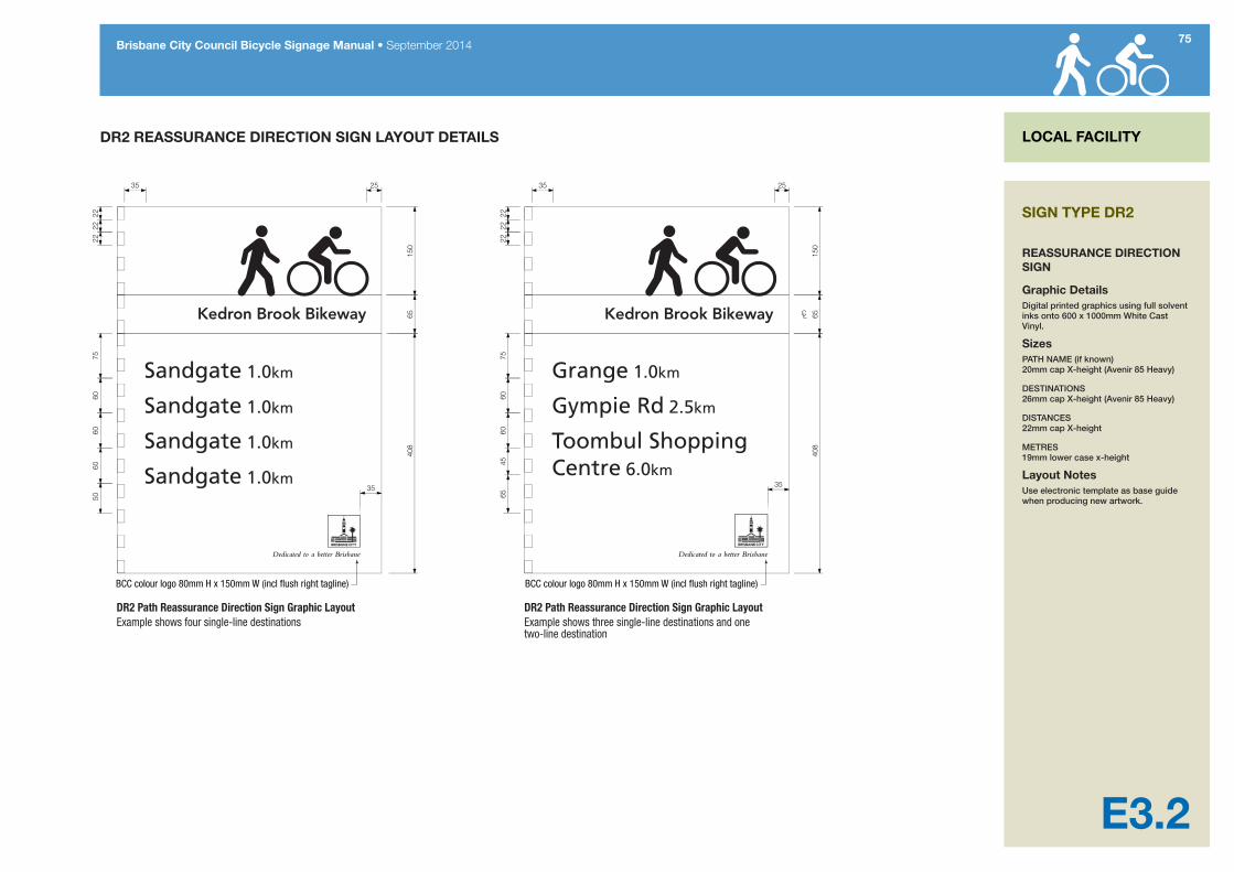
DR2 REASSURANCE DIRECTION SIGN LAYOUT DETAILS
DR2 Path Reassurance Direction Sign Graphic LayoutExample shows four single-line destinations
DR2 Path Reassurance Direction Sign Graphic LayoutExample shows three single-line destinations and one two-line destination
BCC colour logo 80mm H x 150mm W (incl �ush right tagline) BCC colour logo 80mm H x 150mm W (incl �ush right tagline)
SIGN TYPE DR2
REASSURANCE DIRECTION SIGN
Graphic DetailsDigital printed graphics using full solvent inks onto 600 x 1000mm White Cast Vinyl.
SizesPATH NAME (if known) 20mm cap X-height (Avenir 85 Heavy)
DESTINATIONS 26mm cap X-height (Avenir 85 Heavy)
DISTANCES 22mm cap X-height
METRES 19mm lower case x-height
Layout NotesUse electronic template as base guide when producing new artwork.

76Brisbane City Council Bicycle Signage Manual • September 2014
E4.0
LOCAL FACILITY DISTANCE/DIRECTION PAVEMENT MARKINGS LOCAL FACILITY
PURPOSEDistance/direction pavement markers indicate the distance travelled by a pathway user between a nominated start and end point.
Distance/direction markers enable users to track the distance they have travelled for recreational/ exercise/ training purposes, as well reveal how far along the path they are in case of an emergency.
LOCATIONDistance/direction markers are only installed:• on a section of a path/bikeway that has
value for a local community as a training/fitness walking route; or
• to provide reassurance along an isolated bikeway or stretch of pathway.
Distance markers are painted every 200 metres and are accompanied by a pedestrian and/ or bicycle symbol (refer to Typical Pathway Plan).
Where paths are separated (rather than shared), the distance markers are to be painted on the pedestrian side.
GROUND TRUTHINGThe suitability of the stretch of path for distance markers needs to be assessed on consistency in path width and the type of pathway (i.e. continuous path in a remote location and not part of the bikeway network.
SIGN TYPE ID1
DISTANCE PAVEMENT MARKER SIGNE4.1 Construction and Graphic Details
E4.2 Typical Pathway Plan

77Brisbane City Council Bicycle Signage Manual • September 2014
LOCAL FACILITY
E4.1
ID-1 PATH DISTANCE/DIRECTION PAVEMENT MARKER
0.0km 0.0km
CL
350
75
590
8032
580
Typical path colour
7530
325
7525
30
ID1 Path Distance/Direction Marker Graphic LayoutFor path pedestrian use only
ID1 Path Distance/Direction Marker Graphic LayoutFor path pedestrian use only
Sign content notes1. Distances less than 10km are shown to
the nearest 100 metres in standard decimal form.
2. Distances less than one kilometre are shown in metres (rounded to the nearest 100 metres eg: 300m) with no space in between numerals and the ‘m’ abbreviation.
3. Distances below 500m are not shown.4. Use standard abbreviations where
space requires. See Table 4 in Part 4 of this manual.
SIGN TYPE ID1 (cont’d)
DISTANCE PAVEMENT MARKER SIGN
Construction DetailsUse anti-slip durable external grade paint to BCC S150 Roadworks Specification. Cut out stencil to concrete or bitumen pathway and paint applied.
Graphic DetailsSYMBOL Blue Symbol on White Background
GRAPHICS White Graphics on Blue Symbol
TEXT Blue text on White Background
FONT Distance = Avenir 85 Heavy ‘km’ = Avenir 55 Roman All other text = Standards Australia MUTCD Series D 49mm cap X-height text with 35% height increase = 75mm cap X-height. Ensure lettering is centred.
Distance NotesDistance in kilometres to be painted every 500 metres.

78Brisbane City Council Bicycle Signage Manual • September 2014
LOCAL FACILITY
E4.2
ID-1 PATH DISTANCE/DIRECTION PAVEMENT MARKER LAYOUT DETAILS
8.0km
7.5km
7.0km 8.0km
7.5km
7.0km
SIGN TYPE ID1 (cont’d)
DISTANCE PAVEMENT MARKER SIGN
Typical Pathway PlanDistance markers are painted every 500 metres and are accompanied by a pedestrian and/ or bicycle symbol.
Where paths are separated (rather than shared), the distance markers are to be painted on the pedestrian side.

79Brisbane City Council Bicycle Signage Manual • September 2014
E5.0
LINKED STREET PAVEMENT INDICATORS LOCAL FACILITY
PURPOSELinked street pavement indicators are used in conjunction with DR1 fingerboards to indicate all path links with the local street system. This type of indicator is only used on paved links (this includes access ramps) to adjacent streets. Pavement indicators show the name of street linked to the main path by the access path.
LOCATIONLinked street pavement markers are placed at the start and the end of all paths that link the main path to the local street system or other parallel path systems. In situations where the linked street is not visible from the main path, the ID2 pavement indicator should include the prefix “EXIT TO…” followed by the distance to the listed street. This is shown in metres rounded up to the nearest 100 metres. Distances less than 100 metres are never shown.
DR1 path fingerboards, when used at the same locations as linked street pavement indicators, are usually used to indicate local facilities which are beyond the end of the access path. Where the linked-to street/road is an important trip generator for both walkers and local cyclists, a DR1-1 path fingerboard may also be placed at the junction to indicate this linked street/road.
Linked street pavement markers are always used at the both ends of the link path and applied to the path surface (1.0m before the link meets the main path and 1.0m before the link meets the local street system). Path pavement markers are always installed even if a street sign is visible from the path end.
Linked street pavement markers are used on a main path immediately before it crosses a street or road or joins the local street system. Where the main path terminates or crosses at a local street, the pavement indicator is located one metre prior to end of the path surface and orientated to face the direction of path users leaving the main path.
Linked street pavement indicators are primarily intended as a wayfinding aid to pedestrian path users. They are not designed to be read by bicycle riders travelling at any speed and should not be used as advance direction indicators prior to intersections.
GROUND TRUTHINGStreet exit markers must only be placed at established path exits (i.e. where a sealed path with kerb ramp to the road is provided).
SIGN TYPE ID2
LINKED STREET PAVEMENT INDICATOR
ID2-1Street name only indicator Refer to drawing E5.1 for graphic and construction details
ID2-2Exit to street name indicator Refer to drawing E5.1 for graphic and construction details
ID2-1 Street name only indicator ID2-2 Exit to street name indicator
SHORT MESSAGE WITH DISTANCE TO STREETSHORT NAME
MEDIUM NAME
LONG NAME
LONG MESSAGE WITHOUT DISTANCE TO STREET
80Brisbane City Council Bicycle Signage Manual • September 2014
LOCAL FACILITY
E5.1
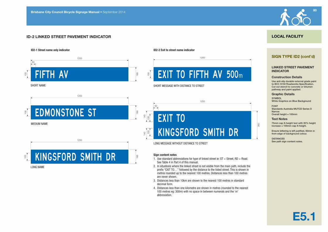
ID-2 LINKED STREET PAVEMENT INDICATOR
Sign content notes1. Use standard abbreviations for type of linked street ie: ST = Street, RD = Road.
See Table 4 in Part 4 of this manual.2. In situations where the linked street is not visible from the main path, include the
pre�x “EXIT TO…” followed by the distance to the listed street. This is shown in metres rounded up to the nearest 100 metres. Distances less than 100 metres are never shown.
3. Distances less than 10km are shown to the nearest 100 metres in standard decimal form.
4. Distances less than one kilometre are shown in metres (rounded to the nearest 100 metres eg: 300m) with no space in between numerals and the ‘m’ abbreviation.
SIGN TYPE ID2 (cont’d)
LINKED STREET PAVEMENT INDICATOR
Construction DetailsUse anti-slip durable external grade paint to BCC S150 Roadworks Specification. Cut out stencil to concrete or bitumen pathway and paint applied.
Graphic DetailsSYMBOL White Graphics on Blue Background
FONT Standards Australia MUTCD Series D Narrow Overall height = 100mm
Text Notes75mm cap X-height text with 35% height increase = 100mm cap X-height.
Ensure lettering is left justified, 60mm in from edge of background colour.
DISTANCES See path sign content notes.

81Brisbane City Council Bicycle Signage Manual • September 2014
E6.0
PATH-USE BEHAVIOUR PAVEMENT MESSAGES LOCAL FACILITY
PURPOSEWhere continuing instances of poor path user behaviour and conflict between different types of users are recorded, path-use pavement messages may be selectively applied to improve path operation and to increase enjoyment and mutual respect among path users.
LOCATIONThese pavement markings are for use on high-volume pathways or where shared path conflict has been often reported by the community.
SHARE THE PATH legends are placed on the main path near access points.
KEEP LEFT and RING YOUR BELL legends are placed intermittently on a path, at distances no closer than 400m apart.
SLOW DOWN legends should only be placed at known ‘hot spots’ of speeding cyclists, or at blind/ narrow curves in the path.
DOGS ON LEASH legends are placed near path access points and in areas where uncontrolled dogs have been regularly reported.
The suggested pavement markings are not prescriptive and other concepts could be included.
GROUND TRUTHINGLocations are selected where there are no existing pedestrian or bike symbols, to avoid clutter and over-use of this medium.
SIGN TYPE ID3
PATH-USE BEHAVIOUR PAVEMENT MESSAGES
ID3-1a-gPath-use behaviour messages for paths less than 2.5m wide Refer to drawing E6.1 for graphic and construction details
ID3-2a-gPath-use behaviour messages for paths greater than 2.5m wide Refer to drawing E6.2 for graphic and construction details

82Brisbane City Council Bicycle Signage Manual • September 2014
LOCAL FACILITY
E6.1
ID-3 PATH-USE BEHAVIOUR PAVEMENT MESSAGES
ID3-1a TYPICAL LAYOUT - for Pathway less than 2500mm
TYPICAL GRAPHIC LAYOUTS - ADDITIONAL MESSAGES
820
350
100
100
200mmfrom edge
650 min to centre line
Centre lineof marking
b1-3DI
490
c1-3DI
540
d1-3DI
540
e1-3DI
790
f1-3DI
550
g1-3DI
765
Typical pathway <2500mm
Edg
e of
pat
hway
100
Sign content notes1. Messages should paced at least 100m from other path messages
to avoid clutter and overuse of the medium,
SIGN TYPE ID3-1
FOR USE ON PATHS UP TO 2.5m WIDE
Construction DetailsUse anti-slip durable external grade paint to BCC S150 Roadworks Specification. Cut out stencil to concrete or bitumen pathway and paint applied.
Graphic DetailsPICTOGRAM AND TEXT White Graphics direct to surface
FONT Standards Australia MUTCD Series D Overall height = 100mm
83Brisbane City Council Bicycle Signage Manual • September 2014
LOCAL FACILITY
E6.2
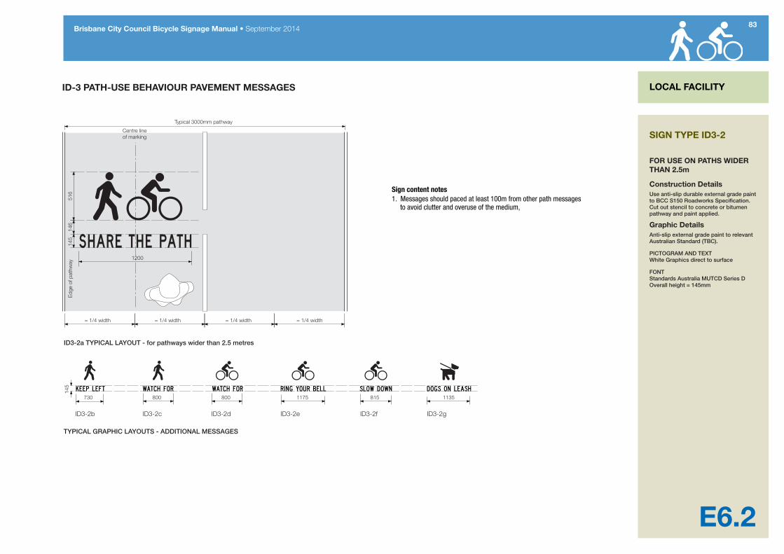
ID-3 PATH-USE BEHAVIOUR PAVEMENT MESSAGES
ID3-2a TYPICAL LAYOUT - for pathways wider than 2.5 metres
ID3-2b
TYPICAL GRAPHIC LAYOUTS - ADDITIONAL MESSAGES
1200
516
145
146
= 1/4 width = 1/4 width = 1/4 width = 1/4 width
Centre lineof marking
730 800 800 1175 815 1135
Typical 3000mm pathway
Edg
e of
pat
hway
145
ID3-2g ID3-2fID3-2eID3-2dID3-2c
Sign content notes1. Messages should paced at least 100m from other path messages
to avoid clutter and overuse of the medium,
SIGN TYPE ID3-2
FOR USE ON PATHS WIDER THAN 2.5m
Construction DetailsUse anti-slip durable external grade paint to BCC S150 Roadworks Specification. Cut out stencil to concrete or bitumen pathway and paint applied.
Graphic DetailsAnti-slip external grade paint to relevant Australian Standard (TBC).
PICTOGRAM AND TEXT White Graphics direct to surface
FONT Standards Australia MUTCD Series D Overall height = 145mm
84Brisbane City Council Bicycle Signage Manual • September 2014
E7.0
PATH-USE BEHAVIOUR SIGNAGE LOCAL FACILITY
PURPOSEWhere continuing instances of poor path user behaviour and conflict between different types of users are recorded, path-use pavement signs may be selectively applied to improve path operation and to increase enjoyment and mutual respect among path users.
LOCATIONThis sign is designed for use on high-volume pathways or where shared path conflict has been often reported by the community.
The sign features four key messages: SHARE THE PATH legends are placed on the main path near access points.
KEEP LEFT and RING YOUR BELL legends are placed intermittently on a path, at distances no closer than 400m apart.
SLOW DOWN legends should only be placed at known ‘hot spots’ of speeding cyclists, or at blind/ narrow curves in the path.
DOGS ON LEASH legends are placed near path access points and in areas where uncontrolled dogs have been regularly reported.
The suggested pavement markings are not prescriptive and other concepts could be included.
GROUND TRUTHINGLocations are selected where there are no existing pedestrian or bike symbols, to avoid over-use of this medium.
85Brisbane City Council Bicycle Signage Manual • September 2014
LOCAL FACILITY
E7.1
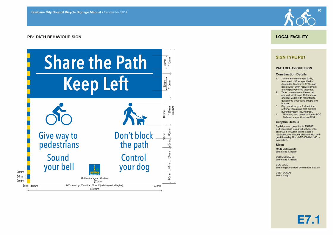
PB1 PATH BEHAVIOUR SIGN
60m
m11
0mm
60mm
40mm
20mm
120m
m40
mm60
mm60
mm
600mm40mm
110m
m60
mm
100m
m30
mm
40mm20mm
20mm20mm
12mm
600m
m
BCC colour logo 65mm H x 120mm W (including centred tagline)
SIGN TYPE PB1
PATH BEHAVIOUR SIGN
Construction Details1. 1.6mm aluminium type 5251,
tempered H38 as specified in Australian Standards 1734, sign panel with 10mm radius corners and digitally printed graphics.
2. Type 1 aluminium stiffener rail centred widthways 100mm less of sheet width with mounted to galvanised post using straps and buckle.
3. Sign panel to type 1 aluminium stiffener rails using self-piercing riveting system (eg. Henrob).
4. Mounting and construction to BCC Reference specification S154.
Graphic DetailsDigital printed graphics in AS2700 B51 Blue using using full solvent inks onto 600 x 1000mm White Class 1 retroreflective material sheeted with anti-graffiti overlay film NI-EF 40801-12-45 or equivalent.
SizesMAIN MESSAGES 60mm cap X-height
SUB MESSAGES 30mm cap X-height
BCC LOGO 60mm high, centred, 20mm from bottom
USER LOGOS 100mm high
SPECIFICATIONS
Section F Local facility signage technical specifications
87Brisbane City Council Bicycle Signage Manual • September 2014
F1.1
SPECIFICATIONS
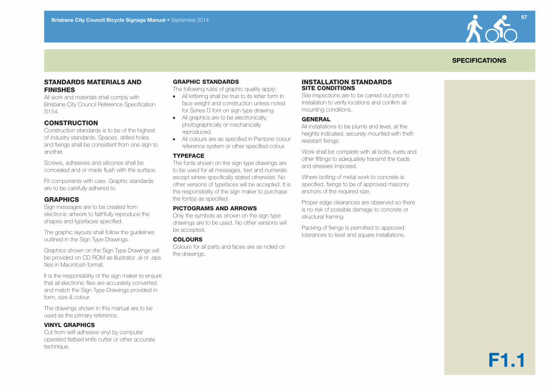
STANDARDS MATERIALS AND FINISHESAll work and materials shall comply with Brisbane City Council Reference Specification S154.
CONSTRUCTIONConstruction standards is to be of the highest of industry standards. Spaces, drilled holes and fixings shall be consistent from one sign to another.
Screws, adhesives and silicones shall be concealed and or made flush with the surface.
Fit components with care. Graphic standards are to be carefully adhered to.
GRAPHICSSign messages are to be created from electronic artwork to faithfully reproduce the shapes and typefaces specified.
The graphic layouts shall follow the guidelines outlined in the Sign Type Drawings.
Graphics shown on the Sign Type Drawings will be provided on CD ROM as Illustrator .ai or .eps files in Macintosh format.
It is the responsibility of the sign maker to ensure that all electronic files are accurately converted and match the Sign Type Drawings provided in form, size & colour.
The drawings shown in this manual are to be used as the primary reference.
VINYL GRAPHICSCut from self-adhesive vinyl by computer operated flatbed knife cutter or other accurate technique.
GRAPHIC STANDARDSThe following rules of graphic quality apply:• All lettering shall be true to its letter form in
face weight and construction unless noted for Series D font on sign type drawing.
• All graphics are to be electronically, photographically or mechanically reproduced.
• All colours are as specified in Pantone colour reference system or other specified colour.
TYPEFACEThe fonts shown on the sign type drawings are to be used for all messages, text and numerals except where specifically stated otherwise. No other versions of typefaces will be accepted. It is the responsibility of the sign maker to purchase the font(s) as specified.
PICTOGRAMS AND ARROWSOnly the symbols as shown on the sign type drawings are to be used. No other versions will be accepted.
COLOURSColours for all parts and faces are as noted on the drawings.
INSTALLATION STANDARDSSITE CONDITIONSSite inspections are to be carried out prior to installation to verify locations and confirm all mounting conditions.
GENERALAll installations to be plumb and level, at the heights indicated, securely mounted with theft-resistant fixings.
Work shall be complete with all bolts, rivets and other fittings to adequately transmit the loads and stresses imposed.
Where bolting of metal work to concrete is specified, fixings to be of approved masonry anchors of the required size.
Proper edge clearances are observed so there is no risk of possible damage to concrete or structural framing.
Packing of fixings is permitted to approved tolerances to level and square installations.
IMPLEMENTATION
Part 3 Implementation guidance

89Brisbane City Council Bicycle Signage Manual • September 2014
G1.1
BICYCLE NETWORK SIGNAGE - SIGN MOUNTING CLEARANCES
2.5
m M
inim
um s
ign
mou
ntin
g he
ight
1.4
m C
yclis
t eye
hei
ght
0.6m minimumclearance tosign supports
Allow suf�cient lateral mounting distance to allow clearance to sign from heavy vehicles considering the effect of road crossfall on the lean of the vehicle
0.6m minimumclearance to
sign. Supportsare �ush with
sign edges
Alternative offset mounting arrangement to provide additional lateral sign clearance
Clearances for cycle network signage
Clearances for map display boards
IMPLEMENTATION
SIGN MOUNTING CLEARANCES

90Brisbane City Council Bicycle Signage Manual • September 2014
IMPLEMENTATION
G1.2
BICYCLE NETWORK SIGNAGE - MULTI-SIGN POLE MOUNTING
Additional sign(s) for same route mounted at same level
2.5
m M
inim
um s
ign
mou
ntin
g he
ight
for l
owes
t sig
n
1.4
m C
yclis
t eye
hei
ght
0.6m minimum clearance to sign supports
Allow suf�cient lateral mounting distance to allow
clearance to sign from heavy vehicles considering the effect of road crossfall on the lean of the vehicle
Notes1. See separate diagram for individual
sign layout, typical intersection sign layout and mounting methodology.
2. Signs shown on the sample sign post are FBP-2 bicycle network �ngerboard signs used for marking primary or secondary routes. Local and recreational type signs can be mounted on the same sign pole where these routes branch. Local destination signs and local facility signs are always mounted below (lower level in the sign stack) to bicycle network signage.
3. Direction sign poles are galvanised plated to BCC Standard Speci�ca-tion for outdoor use.
4. Fingerboard signs are mounted on poles using standard �ngerboard mounting brackets. See individual sign design drawings in this manual for bracket details. Brackets should be pinned to prevent accidental movement due to wind or vandalism.
SIGN POLE MOUNTING DETAILS

91Brisbane City Council Bicycle Signage Manual • September 2014
IMPLEMENTATION
G1.3
BICYCLE NETWORK SIGNAGE - FINGERBOARD MOUNTING HIERARCHY FOR NETWORK ROUTE JUNCTIONS
Telephone 200m
Drinking Fountain 200m
Sign stack mounting hierarchyUpper level - primary and secondary bicycle network routesBicycle Network Signage
Middle level - Local destination and local route signage
Lower level - Local facility signage
Notes1. All signs for the route being followed should be mounted at the same level in the stack.2. Signs shown on the sample sign post (above) illustrate the preferred mounting hierarchy: Primary or secondary route being followed (top level of sign stack) FBP-2 bicycle
network �ngerboard signs used for marking all primary or secondary routes. Local destination/local route (middle level of sign stack) FBL-1 local destination
�ngerboard indicating branch route to destination shown on sign. If the route is lengthy, markers will be used to indicate intermediate turnings along route.
Local facility signage (lower level of sign stack) DR1-1 or DR1-2 signs are mounted as shown to indicate nearby facilities and streets in the local street system which can be accessed from the route. Local facility signage is always mounted on the lower level of the sign stack below all other bicycle network signage.
3. Fingerboard signs are mounted to poles using standard �ngerboard mounting brackets. See individual design detail diagrams in this manual for details.
4. See separate diagrams for individual sign layouts and mounting methodology.
SIGN MOUNTING HIERARCHY
92Brisbane City Council Bicycle Signage Manual • September 2014
G2.0
OPTIONAL ROUTE BRANDING FOR PRIMARY CYCLE ROUTES IMPLEMENTATION
The primary cycle route signage system makes provision for the naming of cycle routes where these already exist (ADPNR and RDPNR sign variations). Naming routes is, however, cumbersome. Naming routes does not necessarily improve wayfinding and can place heavy demands on available sign space and can consequently increase the size of signs.
Lengthy route names are to be avoided. Where the length of a route name exceeds the available sign length (usually determined by the length of the longest listed destination) an abbreviated form or a smaller letter size may need to be used. When used, named route indication is limited to signs at the start and finish of the named route and to important junctions where other major routes enter.
Longer recreational and tourist routes are being developed throughout Queensland for a variety of purposes ranging from local recreational paths to long distance rail trails. These routes often pass through a number of local government areas. To give the route its own identity, local governments can cooperate to give the route a distinctive branding and a promotional identity which encompasses design elements such as path logo, specialist wayfinding and facilities signage designs.
The preferred way to identify tourism and recreational routes, along with more easily identifiable urban routes, is by branding – using an easily recognisable logo or symbol to mark the route. Humans respond quicker to symbols and graphical shapes and can read them from far greater distances than lettering or words. Logos are very compact and so require very little precious sign space.
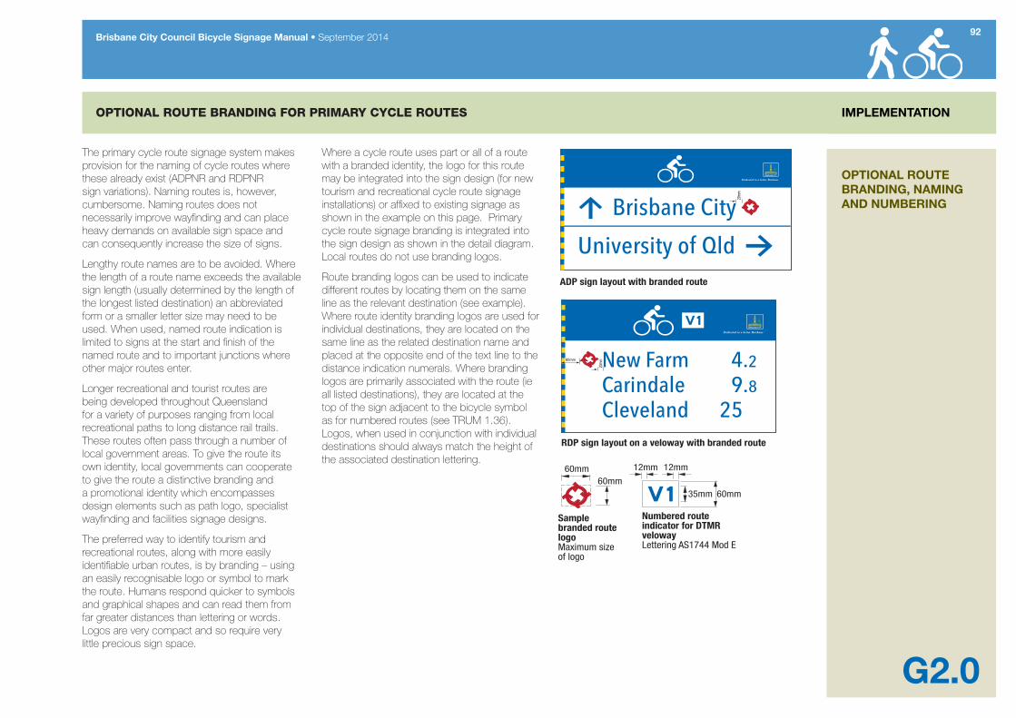
Where a cycle route uses part or all of a route with a branded identity, the logo for this route may be integrated into the sign design (for new tourism and recreational cycle route signage installations) or affixed to existing signage as shown in the example on this page. Primary cycle route signage branding is integrated into the sign design as shown in the detail diagram. Local routes do not use branding logos.
Route branding logos can be used to indicate different routes by locating them on the same line as the relevant destination (see example). Where route identity branding logos are used for individual destinations, they are located on the same line as the related destination name and placed at the opposite end of the text line to the distance indication numerals. Where branding logos are primarily associated with the route (ie all listed destinations), they are located at the top of the sign adjacent to the bicycle symbol as for numbered routes (see TRUM 1.36). Logos, when used in conjunction with individual destinations should always match the height of the associated destination lettering.
35mm 60mm
Numbered route indicator for DTMR velowayLettering AS1744 Mod E
12mm 12mm
Sample branded route logoMaximum size of logo
60mm60mm
60mm
20mm
20mm
ADP sign layout with branded route
RDP sign layout on a veloway with branded route
OPTIONAL ROUTE BRANDING, NAMING AND NUMBERING

93Brisbane City Council Bicycle Signage Manual • September 2014
G3.0
ABBREVIATIONS IMPLEMENTATION
Where a destination name is lengthy and greatly increases the potential size of a sign, an abbreviation may be used to reduce the overall size and cost of the sign.
Table 4 lists abbreviations which may be used on BCC bicycle network signage. Contact the BCC Bikeway Team for advice on other words not listed below.
Table 4 – Sign abbreviations
Name Abbreviation
Avenue Av
Brook Bk
Court Ct
Creek Ck
Crescent Cr
East East
Highway Hwy
Island Is
Junction Jct
Kilometre, also Kilometres Km
Kilometres per hour Km/h
Metre m
Motorway Mwy
Mountain Mt
North Nth
Parade Pde
Park Pk
Queensland QLD
Railway Rly
Reserve Res
Road Rd
South Sth
Square Sq
Station Stn
Street St
Terrace Tc
University Uni
West West
SIGN ABBREVIATIONS

MAINTENANCE
Section H Sign maintenance
95Brisbane City Council Bicycle Signage Manual • September 2014
H1.1
MAINTENANCE
GENERAL CLEANINGStep 1Wipe clean with mild detergent and soft lint-free cloth.
Step 2When panels have dried, apply Mr Sheen or similar.
Note - DO NOT use abrasive cleaners, solvents or chemicals.
TOUCH UP PAINTUse only 2 pack polyurethane paint (in the specified colours) when repairing minor chips, cracks, etc.
For major damage, panels will need to be removed and sprayed professionally.
GRAFFITI REMOVALProcedure as outlined below:
Step 1Use general purpose thinners such as Acetic Acid Alcohol, Toluene or IPA (Isopropyl Alcohol) to clean graffiti from the surface.
Step 2Wipe off with clean white rag (Do not re-use dirty rags). If more than 2 applications are needed to remove stubborn stains, rinse the area with clean water and wipe dry before additional application.
Step 3Rinse all cleaned surfaces with water.
Step 4Allow surface to dry. Disregard used rags in closed container.
MAINTENANCE
Appendix A Focal Point Signing Map

Brisbane City Council Bicycle Signage Manual • September 201497
App A
SAMPLE SECTION FROM THE BCC/SEQ FOCAL POINT SIGAGE MAP (DECEMBER 2013)
Map legend
Primary/secondary cycle route
Focal point
Terminal focal point
Sub destination
City/ town centre
SIGNAGE PLANNING
The map shown on this page is a sample section of a Brisbane City Council portion of the SEQ Focal Point Signing Map for bicycle networks.
A focal point map is a planning tool used by the managers/owners of regional bicycle networks. Focal point maps typically will show the planned and existing regional bicycle network and only those destinations which will appear on directional signage for the network.
A key aim of cycle network focal point mapping is to achieve rigid consistency in the use of named locations so that a coherent system of signage can be developed which will enable direct and unambiguous navigation across the cycle network.
The portion of the BCC/SEQ Focal Point Map shown on this page was current at the time of publication of this manual. Focal point mapping is maintained by Council and TMR and is updated when changes occur in the planning and implementation of bicycle network facilities. The current version of the BCC Focal Point Map for the SEQ bicycle network should be consulted before embarking on any bicycle route signing project.
Contact the Manager responsible for the BCC Bikeways Network for further details.

Top Related