


Languages
Pages
Legal


AE3011
Semester 1; 2012/13
By
Jan Niklewicz CEng. MIMechE
Aerospace Structures and Mechanics

Jan Niklewicz
Managing Director JNDC Ltd Specialist Engineering and Product design Company
Mainly in the Aerospace field
Managing Director Kwikbolt Ltd Design and development and supply of specialist slave fasteners for the
aerospace industry Clients: Lockheed Martin, Airbus, Rolls-Royce, Leyland Trucks, MEP, Rediweld Ltd as
well us individuals and SME’s
Previous Director of Mechanical Engineering at KU
Lead Engineer –Composites centre NP
MSc Imperial College
BEng(Hons) Kingston University

Torsion of Closed, Thin-walled Tubes
(Bredt-Batho Theory)
volumeG
U S 2
2
When a material is subjected to a shear
stress, τ, the strain energy stored is given
by :
Hence, the energy stored in an axial
element of length L, width ds and thickness
t (see Figure 1) is :
dstLG
U S2
2

Torsion of Closed, Thin-walled Tubes
(Bredt-Batho Theory)
The total strain energy, U, in the tube will be
given by:
i.e.
where q= t is the shear flow which will be
constant around the section .
t
ds
G
tL = ds t L
G= U 22
222
t
ds
G 2
Lq = U
2

Torsion of Closed, Thin-walled Tubes
(Bredt-Batho Theory)
The force on the element ds is
τtds = qds .
Taking moments about O gives:
qpds = 2qdA since
Integrating gives :
T = 2Aq
Therefore
ds p 2
1 = dA
dA q 2 = T
2A
T = q
tA
T = 2

Torsion of Closed, Thin-walled Tubes
(Bredt-Batho Theory)
If the tube twists through an angle, θ, the
work done will be given by :
Equating the work done to the total
internal strain energy gives:
ie:
T 2
1 = WD
t
ds
G 2
Lq = T
2
12
t
ds
GA
TL =
t
ds
GT
Lq =
2
24
Torsion of Closed, Thin-walled Tubes
(Bredt-Batho Theory)
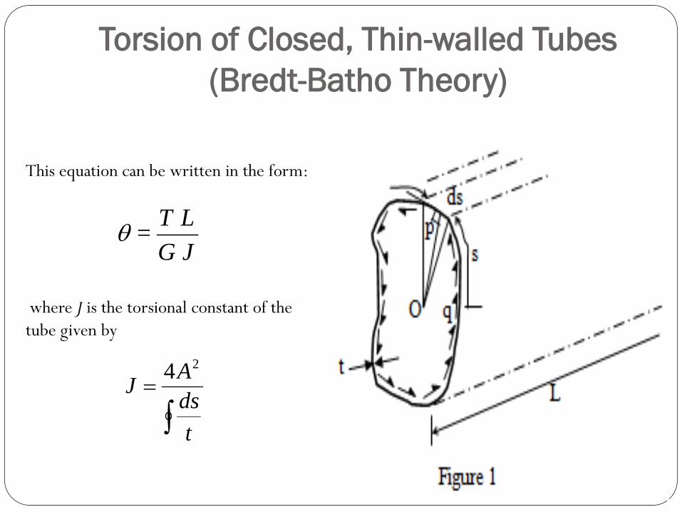
This equation can be written in the form:
where J is the torsional constant of the
tube given by
JG
L T =
t
ds
AJ
24

Torsion of Closed, Thin-walled Tubes
(Bredt-Batho Theory)
Hence the rate of twist per unit length
will be given by :
t
ds
2AG
q =
dz
d =
L

Torsion of Closed, Thin-walled Tubes
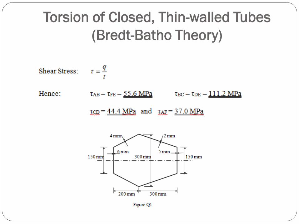
(Bredt-Batho Theory) Example 1
A 5 m long tailplane has the uniform cross-section shown in Figure Q1. It is
subjected to a torque of 50 kNm. Find the shear stress distribution around
the section and the angle of twist throughout the length assuming that the
centre of twist lies at the centroid of the section. Take G = 30 GPa.

Torsion of Closed, Thin-walled Tubes
(Bredt-Batho Theory)
Torsion of Closed, Thin-walled Tubes
(Bredt-Batho Theory)

Torsion of Closed, Thin-walled Tubes
(Bredt-Batho Theory)

Torsion of Multi-cell Tubes
t
ds
AG
q
dz
d
2
For single cell tubes : T = 2Aq
And
These equations may be adapted for multi-cell tubes
as follows :

Torsion of Multi-cell Tubes
The applied torque T will be the sum of the torques induced in the individual cells i.e.
R
N
R
RqAT
1
2
Torsion of Multi-cell Tubes
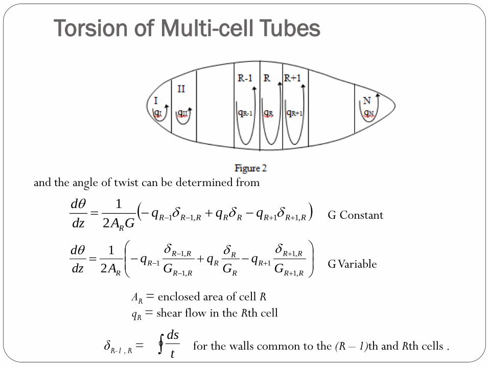
and the angle of twist can be determined from
G Constant
G Variable
AR = enclosed area of cell R
qR = shear flow in the Rth cell
δR-1 , R = for the walls common to the (R – 1)th and Rth cells .
RRRRRRRR
R
qqqGAdz
d,11,11
2
1
RR
RR
R
R
RR
RR
RR
R
R Gq
Gq
Gq
Adz
d
,1
,1
1
,1
,1
12
1
t
ds

Torsion of Multi-cell Tubes
Note that at any junction, for equilibrium q1 = q2 + q3.

Torsion of Multi-cell Tubes
Example 2
The tailplane in Example 1 is modified to form a 2-cell section as shown in Figure Q2.
Find the shear stress distribution and the angle of twist over a 5 m length of the
section. Take G = 30 GPa.

Torsion of Multi-cell Tubes
Let shear flows in cells and be q1 and q2 respectively.
A1 = ½(150 + 300) × 200 = 45000 mm2
A2 = ½(300 + 150) × 300 = 67500 mm2

Cell :
RRRRRRRR
R
qqqGAdz
d,11,11
2
1

Cell:
RRRRRRRR
R
qqqGAdz
d,11,11
2
1
1 2
2
1389.2 50
2 67500
dq q
dz G

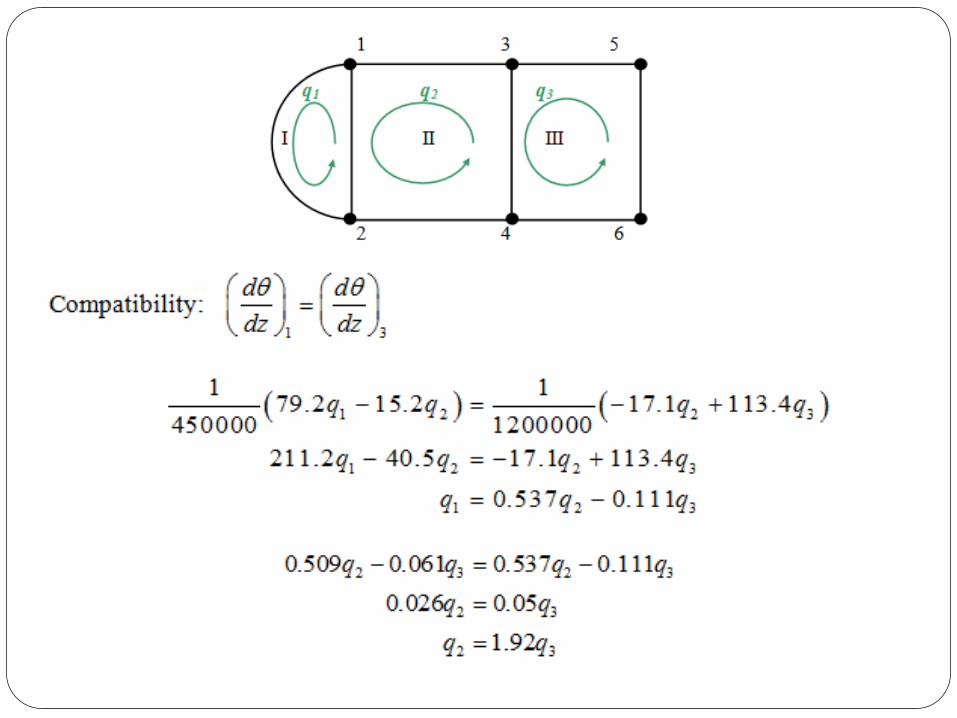
Compatibility: 1 2
d d
dz dz


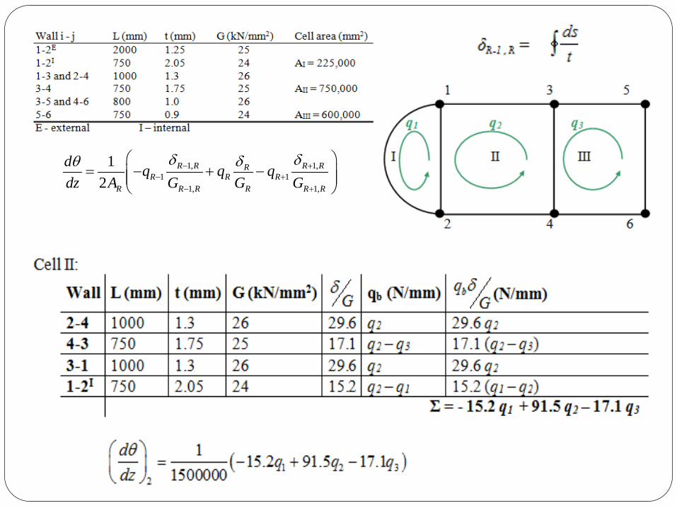
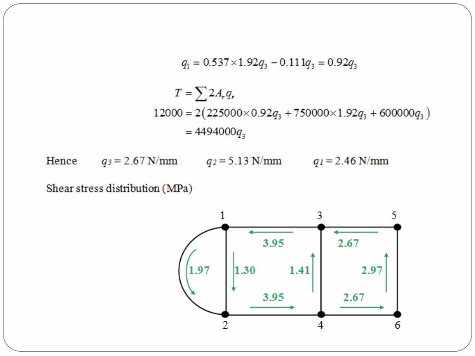
Example 3
Calculate the shear stress distribution
in the walls of the three-cell tube
shown in the diagram when it is
subjected to an anticlockwise
torque of 12 kNm. Assume Bredt-
Batho theory holds and that the
tube has the properties shown in
the table below.

1, 1,
1 1
1, 1,
1
2
R R R RRR R R
R R R R R R
dq q q
dz A G G G
1, 1,
1 1
1, 1,
1
2
R R R RRR R R
R R R R R R
dq q q
dz A G G G

1, 1,
1 1
1, 1,
1
2
R R R RRR R R
R R R R R R
dq q q
dz A G G G


Tutorial Examples

Tutorial Examples
Top Related