


Languages
Pages
Legal


APPLICATION NOTE
Copyright © 2012, Juniper Networks, Inc. 1
BRANCH SRX SERIES AND J SERIES CHASSIS CLUSTERING Configuring Chassis Clusters on Branch SRX Series Services Gateways and J Series Services Routers

2 Copyright © 2012, Juniper Networks, Inc.
APPLICATION NOTE - Branch SRX Series and J Series Chassis Clustering
Table of ContentsIntroduction . . . . . . . . . . . . . . . . . . . . . . . . . . . . . . . . . . . . . . . . . . . . . . . . . . . . . . . . . . . . . . . . . . . . . . . . . . . . . . . . . . . . . . . . . . . . . . . . . . . . .3
Scope . . . . . . . . . . . . . . . . . . . . . . . . . . . . . . . . . . . . . . . . . . . . . . . . . . . . . . . . . . . . . . . . . . . . . . . . . . . . . . . . . . . . . . . . . . . . . . . . . . . . . . . . . . .3
Design Considerations . . . . . . . . . . . . . . . . . . . . . . . . . . . . . . . . . . . . . . . . . . . . . . . . . . . . . . . . . . . . . . . . . . . . . . . . . . . . . . . . . . . . . . . . . . . .3
Hardware Requirements . . . . . . . . . . . . . . . . . . . . . . . . . . . . . . . . . . . . . . . . . . . . . . . . . . . . . . . . . . . . . . . . . . . . . . . . . . . . . . . . . . . . . . . .3
Software Requirements . . . . . . . . . . . . . . . . . . . . . . . . . . . . . . . . . . . . . . . . . . . . . . . . . . . . . . . . . . . . . . . . . . . . . . . . . . . . . . . . . . . . . . . .3
Description and Deployment Scenario . . . . . . . . . . . . . . . . . . . . . . . . . . . . . . . . . . . . . . . . . . . . . . . . . . . . . . . . . . . . . . . . . . . . . . . . . . . . .3
Feature Description . . . . . . . . . . . . . . . . . . . . . . . . . . . . . . . . . . . . . . . . . . . . . . . . . . . . . . . . . . . . . . . . . . . . . . . . . . . . . . . . . . . . . . . . . . . .3
Redundant Ethernet Interfaces . . . . . . . . . . . . . . . . . . . . . . . . . . . . . . . . . . . . . . . . . . . . . . . . . . . . . . . . . . . . . . . . . . . . . . . . . . . . . . . . . .7
Link Aggregation Interfaces and LACP . . . . . . . . . . . . . . . . . . . . . . . . . . . . . . . . . . . . . . . . . . . . . . . . . . . . . . . . . . . . . . . . . . . . . . . . . . .7
Remote Performance Monitoring . . . . . . . . . . . . . . . . . . . . . . . . . . . . . . . . . . . . . . . . . . . . . . . . . . . . . . . . . . . . . . . . . . . . . . . . . . . . . . . .7
IP Monitoring. . . . . . . . . . . . . . . . . . . . . . . . . . . . . . . . . . . . . . . . . . . . . . . . . . . . . . . . . . . . . . . . . . . . . . . . . . . . . . . . . . . . . . . . . . . . . . . . . . .7
Feature Support and Comparison Matrix . . . . . . . . . . . . . . . . . . . . . . . . . . . . . . . . . . . . . . . . . . . . . . . . . . . . . . . . . . . . . . . . . . . . . . . . .7
Clustering Configuration . . . . . . . . . . . . . . . . . . . . . . . . . . . . . . . . . . . . . . . . . . . . . . . . . . . . . . . . . . . . . . . . . . . . . . . . . . . . . . . . . . . . . . . 8
Disabling a Chassis Cluster . . . . . . . . . . . . . . . . . . . . . . . . . . . . . . . . . . . . . . . . . . . . . . . . . . . . . . . . . . . . . . . . . . . . . . . . . . . . . . . . . . . .10
Cluster Monitoring . . . . . . . . . . . . . . . . . . . . . . . . . . . . . . . . . . . . . . . . . . . . . . . . . . . . . . . . . . . . . . . . . . . . . . . . . . . . . . . . . . . . . . . . . . . . .10
Viewing the Chassis Cluster Status . . . . . . . . . . . . . . . . . . . . . . . . . . . . . . . . . . . . . . . . . . . . . . . . . . . . . . . . . . . . . . . . . . . . . . . . . . . . .10
Viewing the Cluster Statistics . . . . . . . . . . . . . . . . . . . . . . . . . . . . . . . . . . . . . . . . . . . . . . . . . . . . . . . . . . . . . . . . . . . . . . . . . . . . . . . . . . 11
Viewing the Control Link Status . . . . . . . . . . . . . . . . . . . . . . . . . . . . . . . . . . . . . . . . . . . . . . . . . . . . . . . . . . . . . . . . . . . . . . . . . . . . . . . . 11
Viewing the Session . . . . . . . . . . . . . . . . . . . . . . . . . . . . . . . . . . . . . . . . . . . . . . . . . . . . . . . . . . . . . . . . . . . . . . . . . . . . . . . . . . . . . . . . . . . 12
Deployment Scenarios . . . . . . . . . . . . . . . . . . . . . . . . . . . . . . . . . . . . . . . . . . . . . . . . . . . . . . . . . . . . . . . . . . . . . . . . . . . . . . . . . . . . . . . . 12
Active/Passive Cluster . . . . . . . . . . . . . . . . . . . . . . . . . . . . . . . . . . . . . . . . . . . . . . . . . . . . . . . . . . . . . . . . . . . . . . . . . . . . . . . . . . . . . . . . . 12
Asymmetric Routing Scenario . . . . . . . . . . . . . . . . . . . . . . . . . . . . . . . . . . . . . . . . . . . . . . . . . . . . . . . . . . . . . . . . . . . . . . . . . . . . . . . . . . 14
Case I: Failures in the Trust Zone RETH . . . . . . . . . . . . . . . . . . . . . . . . . . . . . . . . . . . . . . . . . . . . . . . . . . . . . . . . . . . . . . . . . . . . . . 15
Case II: Failures in the Untrust Zone Interfaces . . . . . . . . . . . . . . . . . . . . . . . . . . . . . . . . . . . . . . . . . . . . . . . . . . . . . . . . . . . . . . . 15
Active/Active Full Mesh. . . . . . . . . . . . . . . . . . . . . . . . . . . . . . . . . . . . . . . . . . . . . . . . . . . . . . . . . . . . . . . . . . . . . . . . . . . . . . . . . . . . . . 17
Special Consideration . . . . . . . . . . . . . . . . . . . . . . . . . . . . . . . . . . . . . . . . . . . . . . . . . . . . . . . . . . . . . . . . . . . . . . . . . . . . . . . . . . . . . . . 17
Cluster Upgrade . . . . . . . . . . . . . . . . . . . . . . . . . . . . . . . . . . . . . . . . . . . . . . . . . . . . . . . . . . . . . . . . . . . . . . . . . . . . . . . . . . . . . . . . . . . . . . .18
In-Band Management of Chassis Clusters . . . . . . . . . . . . . . . . . . . . . . . . . . . . . . . . . . . . . . . . . . . . . . . . . . . . . . . . . . . . . . . . . . . . . . . . .18
Problem Statement . . . . . . . . . . . . . . . . . . . . . . . . . . . . . . . . . . . . . . . . . . . . . . . . . . . . . . . . . . . . . . . . . . . . . . . . . . . . . . . . . . . . . . . . . . . . .18
Description and Deployment Scenario . . . . . . . . . . . . . . . . . . . . . . . . . . . . . . . . . . . . . . . . . . . . . . . . . . . . . . . . . . . . . . . . . . . . . . . . . . . 20
Connecting to a Cluster Using SSH/Telnet . . . . . . . . . . . . . . . . . . . . . . . . . . . . . . . . . . . . . . . . . . . . . . . . . . . . . . . . . . . . . . . . . . . . . 20
In-band Management Through Network and Security Manager . . . . . . . . . . . . . . . . . . . . . . . . . . . . . . . . . . . . . . . . . . . . . . . . . . 21
Updating the IDP Signatures . . . . . . . . . . . . . . . . . . . . . . . . . . . . . . . . . . . . . . . . . . . . . . . . . . . . . . . . . . . . . . . . . . . . . . . . . . . . . . . . . . 22
Using SNMP . . . . . . . . . . . . . . . . . . . . . . . . . . . . . . . . . . . . . . . . . . . . . . . . . . . . . . . . . . . . . . . . . . . . . . . . . . . . . . . . . . . . . . . . . . . . . . . . . 22
Software Upgrades . . . . . . . . . . . . . . . . . . . . . . . . . . . . . . . . . . . . . . . . . . . . . . . . . . . . . . . . . . . . . . . . . . . . . . . . . . . . . . . . . . . . . . . . . . . . . 24
Summary . . . . . . . . . . . . . . . . . . . . . . . . . . . . . . . . . . . . . . . . . . . . . . . . . . . . . . . . . . . . . . . . . . . . . . . . . . . . . . . . . . . . . . . . . . . . . . . . . . . . . . 27
About Juniper Networks . . . . . . . . . . . . . . . . . . . . . . . . . . . . . . . . . . . . . . . . . . . . . . . . . . . . . . . . . . . . . . . . . . . . . . . . . . . . . . . . . . . . . . . . . 27
List of FiguresFigure 1: Junos OS redundancy model . . . . . . . . . . . . . . . . . . . . . . . . . . . . . . . . . . . . . . . . . . . . . . . . . . . . . . . . . . . . . . . . . . . . . . . . . . . . 4
Figure 2: Device clustering . . . . . . . . . . . . . . . . . . . . . . . . . . . . . . . . . . . . . . . . . . . . . . . . . . . . . . . . . . . . . . . . . . . . . . . . . . . . . . . . . . . . . . . 5
Figure 3: Active/passive cluster . . . . . . . . . . . . . . . . . . . . . . . . . . . . . . . . . . . . . . . . . . . . . . . . . . . . . . . . . . . . . . . . . . . . . . . . . . . . . . . . . . 13
Figure 4: Asymmetric routing scenario . . . . . . . . . . . . . . . . . . . . . . . . . . . . . . . . . . . . . . . . . . . . . . . . . . . . . . . . . . . . . . . . . . . . . . . . . . . . 15
Figure 5: Active/active full mesh scenario . . . . . . . . . . . . . . . . . . . . . . . . . . . . . . . . . . . . . . . . . . . . . . . . . . . . . . . . . . . . . . . . . . . . . . . . . 17
Figure 6: SRX Series clustering model . . . . . . . . . . . . . . . . . . . . . . . . . . . . . . . . . . . . . . . . . . . . . . . . . . . . . . . . . . . . . . . . . . . . . . . . . . . .19
Figure 7: Common branch deployment scenarios for SRX Series clustering . . . . . . . . . . . . . . . . . . . . . . . . . . . . . . . . . . . . . . . . 20
Figure 8: Adding a cluster as a Virtual Chassis in NSM . . . . . . . . . . . . . . . . . . . . . . . . . . . . . . . . . . . . . . . . . . . . . . . . . . . . . . . . . . . . 21

Copyright © 2012, Juniper Networks, Inc. 3
APPLICATION NOTE - Branch SRX Series and J Series Chassis Clustering
Introduction Modern networks require high availability. In order to accommodate this requirement, Juniper Networks® SRX Series
Services Gateways and J Series Services Routers can be configured to operate in cluster mode, where a pair of devices
can be connected together and configured to operate like a single node, providing device, interface, and service level
redundancy. Starting with the 9.0 release of Juniper Networks® Junos® operating system, Juniper Networks J Series
Services Routers and SRX Series Services Gateways may be deployed using the chassis cluster feature to provide high
availability (HA). For the J Series, this feature is only available with the flow-enabled version of Junos OS. With the
introduction of the SRX Series services gateways for the branch in Junos OS release 9.5, HA is supported on all branch
SRX Series devices.
ScopeThe purpose of this application note is to review the HA chassis clustering feature, together with its limitations and
design considerations. We will also discuss some common use cases and how they relate to their Juniper Networks
ScreenOS® Software NetScreen Redundancy Protocol (NSRP) counterparts.
Design ConsiderationsHigh availability between devices is easily incorporated into enterprise designs and is particularly relevant when
architecting branch and remote site links to larger corporate offices. By leveraging the HA feature, enterprises can
ensure connectivity in the event of device or link failure.
Hardware Requirements• Two identical J Series secure routers per cluster (Juniper Networks J2320 Services Router, J2350 Services Router, J4350
Services Router, or J6350 Services Router) or
• Two identical SRX Series gateways per cluster (Juniper Networks SRX100 Services Gateway, SRX110 Services Gateway,
SRX210 Services Gateway, SRX220 Services Gateway, SRX240 Services Gateway, or SRX650 Services Gateway)
Software Requirements• Flow-enabled Junos OS 9.0 or later for J Series secure routers
• Junos OS release 9.5 and later for SRX Series Services Gateways
Description and Deployment ScenarioChassis clustering between devices may be deployed in either active/passive or active/active scenarios. Junos OS
allows an HA cluster to additionally be used in asymmetric routing scenarios. Code examples are provided throughout
this document, and deployment scenarios are discussed towards the end of the paper.
Feature DescriptionThe HA feature is modeled after redundancy features first introduced in Juniper Networks M Series Multiservice Edge
Routers and T Series Core Routers. We will first give a brief overview of the way Junos OS redundancy works, so that
we can better understand how this model is applied when clustering devices. As Junos OS is designed with separate
control and data planes, redundancy must operate in both. The control plane in Junos OS is managed by Routing
Engines (REs), which perform all the routing and forwarding computations (among many other functions). Once the
control plane converges, forwarding entries are pushed to all Packet Forwarding Engines (PFEs), which are virtualized
on J Series routers. PFEs then perform route-based lookups to determine the appropriate destination for each packet
independent of the REs. This simplistic view of the Junos OS forwarding paradigm is represented in Figure 1.

4 Copyright © 2012, Juniper Networks, Inc.
APPLICATION NOTE - Branch SRX Series and J Series Chassis Clustering
NSR/GR Provide Nonstop Failover
Node0 Node1
REO RE1Switching
Fabric
FPCO FPC1 FPC2 FPC3
Control Plane
Data Plane
The Junos OS Redundancy Model
Figure 1: Junos OS redundancy model
Control plane failover is provided in Junos OS by using graceful restart or nonstop active routing (NSR). In the former,
the router signals a control plane failure to the rest of the network, while continuing to forward traffic on the data
plane (since a control plane failure doesn’t affect the forwarding plane). The rest of the network will continue to use
the restarting router (for a grace period), while the restarting router forms new adjacencies. The backup RE in this
scenario detects the entire configuration, but not the runtime state of the control plane. In a failure, the backup RE has
to recalculate all routing/forwarding tables. Nonstop routing leverages state replication between Routing Engines. In
this case, a restarting router handles control plane failures transparently, as the backup RE takes control of the router
without any assistance from the rest of the network. Routing protocols handle data plane failures, while interface, PFE,
or FPC failovers are handled by diverting traffic through other interfaces, which can be achieved by using conventional
routing protocols, Virtual Router Redundancy Protocol (VRRP), or aggregate interfaces. When enabling a chassis
cluster for J Series routers, Junos OS uses a similar model—less the nonstop routing state replication—to provide
control plane redundancy as shown in Figure 2.

Copyright © 2012, Juniper Networks, Inc. 5
APPLICATION NOTE - Branch SRX Series and J Series Chassis Clustering
Figure 2: Device clustering
The chassis clustering feature supports clustering of two devices and requires two connections between the devices
as previously illustrated. The chassis cluster is seen as a single device by both external devices and administrators of
the cluster. When clustering is enabled, node 1 of the cluster will renumber its interfaces to avoid collisions with node 0.
Depending on the model used (only two devices of the same model can be clustered), node 1 will renumber its interfaces
by adding the total number of system FPCs to the original FPC number of the interface. (On a J Series router, the onboard
ports and each Physical Interface Module (PIM) slot correspond to an FPC.) Accordingly, when clustering two J2320
routers, node 1 will renumber its interfaces as ge-4/0/0 to ge-7/0/0, because a J2320 has three PIM slots and four
standard GbE ports on the system board acting as FPC0. The following table summarizes the renumbering schema.
Table 1: Interface Renumbering
Device Renumbering Constant Node 0 Interface Name Node 1 Interface Name
J2320 4 ge-0/0/0 ge-4/0/0
J2350 5 ge-0/0/0 ge-6/0/0
J4350 7 ge-0/0/0 ge-7/0/0
J6350 7 ge-0/0/0 ge-7/0/0
SRX100/SRX110 1 fe-0/0/0 fe-1/0/0
SRX210 2 ge-0/0/0 ge-2/0/0
SRX220 3 ge-0/0/0 ge-3/0/0
SRX240 5 ge-0/0/0 ge-5/0/0
SRX650 9 ge-0/0/0 ge-9/0/0
After clustering is enabled, the system creates fxp0, fxp1, and fab interfaces. Depending on the platform, fxp0 and fxp1
are mapped to a physical interface. This is not user configurable. The fab interface is user configurable. (However, this
is limited to onboard interfaces in the SRX200 line of services gateways. The following table summarizes the fxp0 and
fxp1 mappings.)
Nonstop Routing/Graceful Restart Provide Nonstop Failover
Node0 Node1
Control Plane
Data Plane
fab0
fab1
Control PlaneProcesses
Node 0
Control PlaneProcesses
Node 1
ForwardingProcesses
Node 0
ForwardingProcesses
Node 1
6 Copyright © 2012, Juniper Networks, Inc.
APPLICATION NOTE - Branch SRX Series and J Series Chassis Clustering
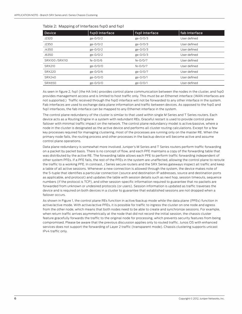
Table 2: Mapping of Interfaces fxp0 and fxp1
Device fxp0 Interface fxp1 Interface fab Interface
J2320 ge-0/0/2 ge-0/0/3 User defined
J2350 ge-0/0/2 ge-0/0/3 User defined
J4350 ge-0/0/2 ge-0/0/3 User defined
J6350 ge-0/0/2 ge-0/0/3 User defined
SRX100 /SRX110 fe-0/0/6 fe-0/0/7 User defined
SRX210 ge-0/0/0 fe-0/0/7 User defined
SRX220 ge-0/0/6 ge-0/0/7 User defined
SRX240 ge-0/0/0 ge-0/0/1 User defined
SRX650 ge-0/0/0 ge-0/0/1 User defined
As seen in figure 2, fxp1 (the HA link) provides control plane communication between the nodes in the cluster, and fxp0
provides management access and is limited to host traffic only. This must be an Ethernet interface (WAN interfaces are
not supported.) Traffic received through the fxp0 interface will not be forwarded to any other interface in the system.
Fab interfaces are used to exchange data plane information and traffic between devices. As opposed to the fxp0 and
fxp1 interfaces, the fab interface can be mapped to any Ethernet interface in the system.
The control plane redundancy of the cluster is similar to that used within single M Series and T Series routers. Each
device acts as a Routing Engine in a system with redundant REs. Graceful restart is used to provide control plane
failover with minimal traffic impact on the network. The control plane redundancy model is active/passive, where a
node in the cluster is designated as the active device and performs all cluster routing calculations. Except for a few
key processes required for managing clustering, most of the processes are running only on the master RE. When the
primary node fails, the routing process and other processes in the backup device will become active and assume
control plane operations.
Data plane redundancy is somewhat more involved. Juniper’s M Series and T Series routers perform traffic forwarding
on a packet by packet basis. There is no concept of flow, and each PFE maintains a copy of the forwarding table that
was distributed by the active RE. The forwarding table allows each PFE to perform traffic forwarding independent of
other system PFEs. If a PFE fails, the rest of the PFEs in the system are unaffected, allowing the control plane to reroute
the traffic to a working PFE. In contrast, J Series secure routers and the SRX Series gateways inspect all traffic and keep
a table of all active sessions. Whenever a new connection is allowed through the system, the device makes note of
the 5-tuple that identifies a particular connection (source and destination IP addresses, source and destination ports
as applicable, and protocol) and updates the table with session details such as next hop, session timeouts, sequence
numbers (if the protocol is TCP), and other session-specific information required to guarantee that no packets are
forwarded from unknown or undesired protocols (or users). Session information is updated as traffic traverses the
device and is required on both devices in a cluster to guarantee that established sessions are not dropped when a
failover occurs.
As shown in Figure 1, the control plane REs function in active/backup mode while the data plane (PFEs) function in
active/active mode. With active/active PFEs, it is possible for traffic to ingress the cluster on one node and egress
from the other node, which means that both nodes need to be able to create and synchronize sessions. For example,
when return traffic arrives asymmetrically at the node that did not record the initial session, the chassis cluster
feature gracefully forwards the traffic to the original node for processing, which prevents security features from being
compromised. Please be aware that the previous discussion applies only to routed traffic. Junos OS with enhanced
services does not support the forwarding of Layer 2 traffic (transparent mode). Chassis clustering supports unicast
IPv4 traffic only.

Copyright © 2012, Juniper Networks, Inc. 7
APPLICATION NOTE - Branch SRX Series and J Series Chassis Clustering
Redundant Ethernet InterfacesAs previously discussed, control plane failures are detected by member nodes, causing the backup node to take
control of the cluster. Conversely, data plane failures rely on routing protocols to reroute traffic or redundant Ethernet
interfaces to overcome interface failures. The concept of redundant Ethernet is fairly simple; two Ethernet interfaces
(one from each node in a cluster) are configured as part of the same redundant Ethernet interface (RETH interface in
Junos OS terminology). The RETH interface is then configured as part of a redundancy group. A redundancy group is
active only on one of the nodes in the cluster, and the redundant Ethernet interfaces that are members of that group
will send (and normally receive) traffic only through the physical interfaces on the active node.
A redundancy group can be configured to monitor one or more physical interfaces. Each monitored interface is given a
weight, which is subtracted from the redundancy group threshold if the interface fails. If the threshold—due to interface
failover—becomes less than zero, the redundancy group transitions state, causing the other node in the cluster to
become active for the group. Consequently, all the redundant Ethernet interfaces that are part of this redundancy
group will use the interfaces on the new node to send (and normally receive) traffic, thus routing traffic around the
failure. Readers familiar with NSRP will note that RETH interfaces are analogous to virtual security interfaces (VSI) on
Juniper Networks ScreenOS® Software-based devices. RETH interfaces, just like VSIs, share the same IP and media
access control (MAC) addresses between the different physical interfaces that are members of the VSI/RETH. The
redundant interfaces send gratuitous Address Resolution Protocol (ARP) messages when failing over and appear as a
single interface to the rest of the network. There are, however, a few significant differences between RETHs and VSIs:
• RETH interfaces always contain the same type of physical Ethernet interfaces—for example, fe-fe or ge-ge.
• VSIs will always force a failover when the physical interface of the active VSI goes down. The state of the redundant
Ethernet interface is purely a function of the state of the redundancy group with which the RETH is associated. A RETH
interface will go down if its active physical interface is down.
• RETH interfaces will only fail over based on the monitoring of physical interfaces.
• IP tracking and zone monitoring are currently not supported in Junos OS.
To be clear, RETH interfaces are not required to provide HA. Session information will be synchronized regardless of the
ingress or egress interface type. Traditional routing protocols can be used to route around failures, but when connecting
to simple devices that do not support routing protocols, redundant Ethernet interfaces can be useful to overcome this
limitation.
Link Aggregation Interfaces and LACPAs of Junos OS 11.2, RETH interfaces may contain LAG interface groups as members. Additionally, the physical
interfaces contained in the LAG group can cross members of the SRX Series chassis cluster. This allows multiple
active physical interfaces between cluster members to participate in the Redundant Ethernet (RETH) and redundancy
protocol (JSRP).
Remote Performance MonitoringAll Junos OS-based devices have the ability to perform Remote Performance Monitoring (RPM), a task running on the
router which monitors hosts using either ICMP, TCP or HTTP, which periodically checks the remote hosts, and keeps a
log history of the packet loss and latency results. This information can be used to monitor upstream routers in an HA
design, and together with IP monitoring, can enable (backup) interfaces or modify the active routing table based on the
probe-results from RPM.
IP MonitoringIP monitoring is the Junos OS equivalent of the ScreenOS Track-IP Feature. This allows an SRX Series device to
monitor upstream hosts, via RPM and dynamically modify the routing table, based on the availability of the hosts being
monitored with RPM.
Feature Support and Comparison MatrixAlthough both protocols were designed to provide the same services, NSRP and JSRP (the protocol used in Junos OS)
do not operate in the same manner and do not provide the same set of features. The following table summarizes the
main differences between the protocols.

8 Copyright © 2012, Juniper Networks, Inc.
APPLICATION NOTE - Branch SRX Series and J Series Chassis Clustering
Table 3: Feature Comparison
Feature JSRP NSRP
Session replication Yes Yes
Application-level gateway (ALG) replication Yes Yes
Network Address Translation (NAT) session replication Yes Yes
IPsec session replication (policy-based VPN) Yes Yes
IPsec session replication (route-based VPN) Yes Yes
Route synchronization N/A Yes
Interface monitoring Yes Yes
Zone monitoring No Yes
Track IP / IP monitoring YesRenamed to IP monitoring
Yes
Remote Performance Monitoring (RPM) Yes No
Asymmetric routing Yes No
Load balancing Yes No
Graceful restart Yes No
Layer 2 mode Yes Junos OS 11.2r2 or higher
Yes
Clustering ConfigurationThis section outlines the steps required to configure J Series chassis clustering. Steps 1 through 3 are the minimum
required. After this minimal configuration, two J Series secure routers will appear as a single device controlling all
interfaces in both nodes. Steps 4 through 6 detail the configuration statements needed to specify the IP addresses
of the management interface (fxp0) and the host name of each cluster node (node 0 and node 1 will have different
management IPs and hostnames). Step 7 describes the configuration needed to add redundant Ethernet interfaces
and the associated redundancy groups.
In this example, we will assume that we are enabling chassis clustering for a pair of J2320 devices, node left and node
right, which are connected back-to-back using interfaces ge-0/0/1 and ge-0/0/3.
Note: If using Factory Config you will need to delete interface units, delete vlans, modify security zones (or delete
security).
1. Delete any configuration used for the FXP and HA Control Link and Fab Link interfaces. The following examples use
the interface names and default configuration for an SRX210 device.
On both nodes:root@left> cliroot@left# set chassis cluster cluster-id 1 node 0 rebootroot@left# delete interface interface-range interfaces-trust members ge-0/0/1root@left# delete interface interface-range interfaces-trust members ge-0/0/2root@left# delete interface ge-0/0/0 root@left# delete security zone security-zone trust interface ge-0/0/0
set interface fab0 fabric

Copyright © 2012, Juniper Networks, Inc. 9
APPLICATION NOTE - Branch SRX Series and J Series Chassis Clustering
Log into each device and enable clustering by setting the appropriate cluster ID in the EEPROM. A reboot is required for
this setting to take effect. Only node 0 and node 1 can be configured, as the current implementation is limited to two
nodes in a cluster. In this example, node 0 (left) and node 1 (right) will be renumbered as illustrated in Table 1.
set chassis cluster cluster-id <n> node <m> rebootOn node left:root@left> set chassis cluster cluster-id 1 node 0 rebootOn node right:root@right> set chassis cluster cluster-id 1 node 1 reboot
Note: Step #1 must be performed in operational mode, not in configuration mode.
After the nodes reboot, they will form a cluster. From this point forward, the configuration of the cluster is going to be
synchronized between the node members. The following commands are entered from the configuration mode on either
of the devices.
After a reboot, note how the prompts change when you enter CLI.
2. Define the interfaces used for the fab connection. These interfaces must be connected back to back, or through a
Layer 2 infrastructure, as shown in Figure 2. As expected, fab0 is the fabric interface of node0, while fab1 is the fabric
interface of node1.
set interface fab0 fabric-options member-interfaces <interface>set interface fab1 fabric-options member-interfaces <interface>
3. Configure the management interface on each device using configuration groups.
set groups node0 system host-name <node0 hostname>set groups node0 interfaces fxp0 unit 0 family inet address <node0 mgmt IP>/<netmask>set groups node1 system host-name <node1 hostname>set groups node1 interfaces fxp0 unit 0 family inet address <node1 mgmt IP>/<netmask>
4. (Optional) Configure device-specific options.
set groups node0 snmp description <node0 snmp sysDesc>set groups node1 snmp description <node1 snmp sysDesc>
5. Apply the group configuration.
set apply-groups “${node}”
6. (Optional) Define the redundancy groups and RETH interfaces if using redundant Ethernet interfaces.
set chassis cluster reth-count <n>set chassis cluster redundancy-group 1 node 0 priority <n>set chassis cluster redundancy-group 1 node 1 priority <n>set interface <interface name> gigether-options redundant-parent reth.<n>

10 Copyright © 2012, Juniper Networks, Inc.
APPLICATION NOTE - Branch SRX Series and J Series Chassis Clustering
The resulting sample configuration is shown below:
#The following declares int ge-0/0/1 in node 0 as the fab interface for the nodeset interface fab0 fabric-options member-interfaces ge-0/0/1#The following declares int ge-4/0/1 in node 1 as the fab interface for the nodeset interface fab1 fabric-options member-interfaces ge-4/0/1#Groups configuration. Configuration parameters specific to each node are set here.set groups node0 system host-name leftset groups node0 interfaces fxp0 unit 0 family inet address 192.168.3.10/24set groups node1 system host-name rightset groups node1 interfaces fxp0 unit 0 family inet address 192.168.3.11/24set apply-groups “${node}”#Define a single RETH interface for the clusterset chassis cluster reth-count 1#Define node 0 as the primary node for reth0set chassis cluster redundancy-group 1 node 0 priority 100set chassis cluster redundancy-group 1 node 1 priority 1#Add interfaces ge-0/0/0 (in node 0) and ge-4/0/0 (ge-0/0/0 in node 1) to the rethset interface ge-0/0/0 gigether-options redundant-parent reth0set interface ge-4/0/0 gigether-options redundant-parent reth0set interfaces reth0 unit 0 family inet address <reth0-ip-address>set interfaces reth1 redundant-ether-options redundancy-group <rg-id>#Define node 0 as the primary node for the control pathset chassis cluster redundancy-group 0 node 0 priority 100set chassis cluster redundancy-group 0 node 1 priority 1
Disabling a Chassis Cluster Disabling clustering is a very simple process—first set the cluster id of each node to 0 and then reboot the nodes.
set chassis cluster cluster-id 0 node 0 reboot
Cluster MonitoringThe following commands can be used to verify the status of a cluster and present a view of the cluster from a node’s
perspective. Statistics are not synchronized between the nodes in the cluster. When debugging clusters, it is useful to
log into each member node and analyze the output from each.
Viewing the Chassis Cluster StatusThe command below shows the different redundant groups configured in the cluster, together with their specified
priorities and the status of each node. This command is useful when trying to determine which RETH interfaces are
active on each node. The special redundancy group 0 refers to the status of the control plane. In this example, node 0
is the primary node for this group and, therefore, it is in charge of all control plane calculations (it acts as the master RE
and runs the control plane processes like rpd, kmd, dhcpd, pppd, and others).
show chassis cluster statusCluster: 1, Redundancy-Group: 0 Device name Priority Status Preempt Manual failover
node0 100 Primary No No node1 1 Secondary No No
Cluster: 1, Redundancy-Group: 1 Device name Priority Status Preempt Manual failover
node0 100 Primary Yes No node1 1 Secondary Yes No
Copyright © 2012, Juniper Networks, Inc. 11
APPLICATION NOTE - Branch SRX Series and J Series Chassis Clustering
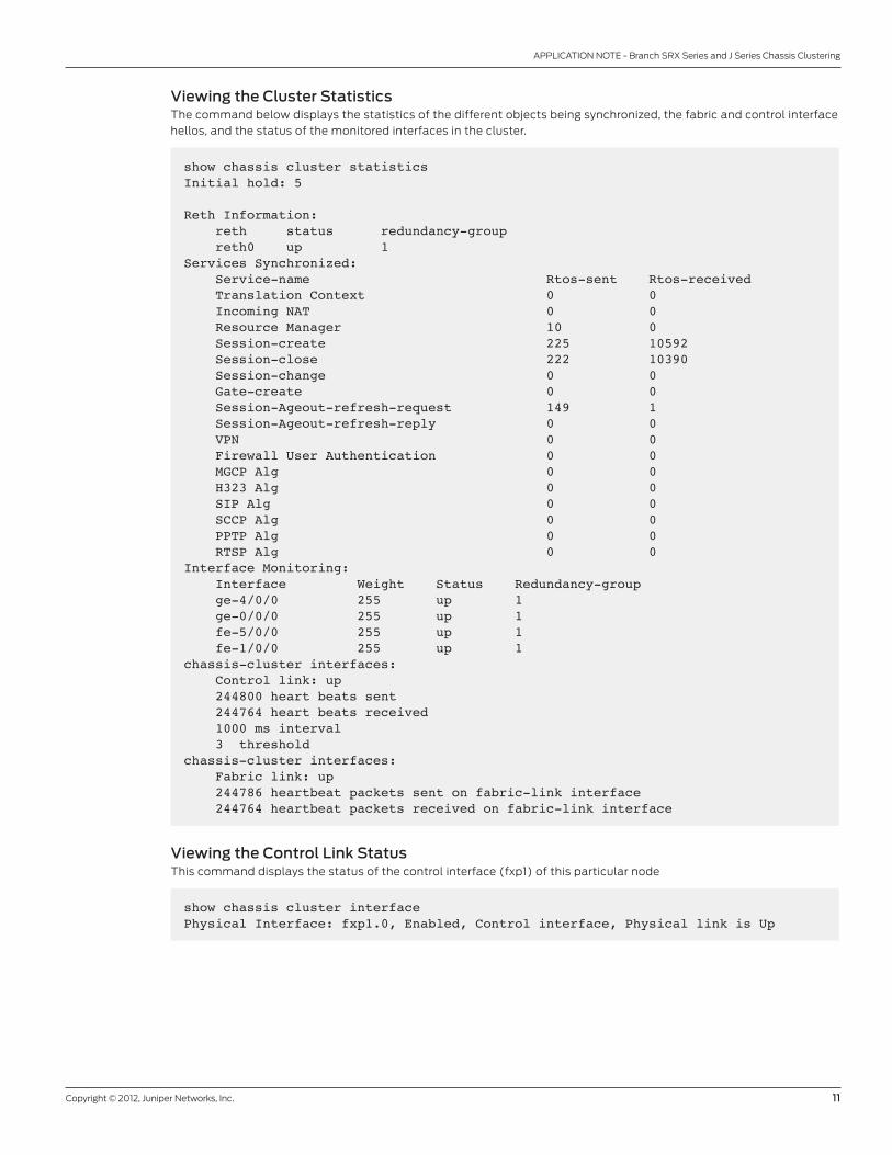
Viewing the Cluster StatisticsThe command below displays the statistics of the different objects being synchronized, the fabric and control interface
hellos, and the status of the monitored interfaces in the cluster.
show chassis cluster statisticsInitial hold: 5 Reth Information: reth status redundancy-group reth0 up 1 Services Synchronized: Service-name Rtos-sent Rtos-received Translation Context 0 0 Incoming NAT 0 0 Resource Manager 10 0 Session-create 225 10592 Session-close 222 10390 Session-change 0 0 Gate-create 0 0 Session-Ageout-refresh-request 149 1 Session-Ageout-refresh-reply 0 0 VPN 0 0 Firewall User Authentication 0 0 MGCP Alg 0 0 H323 Alg 0 0 SIP Alg 0 0 SCCP Alg 0 0 PPTP Alg 0 0 RTSP Alg 0 0 Interface Monitoring: Interface Weight Status Redundancy-group ge-4/0/0 255 up 1 ge-0/0/0 255 up 1 fe-5/0/0 255 up 1 fe-1/0/0 255 up 1 chassis-cluster interfaces: Control link: up 244800 heart beats sent 244764 heart beats received 1000 ms interval 3 thresholdchassis-cluster interfaces: Fabric link: up 244786 heartbeat packets sent on fabric-link interface 244764 heartbeat packets received on fabric-link interface
Viewing the Control Link StatusThis command displays the status of the control interface (fxp1) of this particular node
show chassis cluster interfacePhysical Interface: fxp1.0, Enabled, Control interface, Physical link is Up

12 Copyright © 2012, Juniper Networks, Inc.
APPLICATION NOTE - Branch SRX Series and J Series Chassis Clustering
Viewing the SessionThe command shown below displays the sessions in the session table of each node by specifying the node number.
Synchronized sessions will be seen in both nodes, where they will appear as active in one node and backup in the other.
A detailed view of a session can be obtained by specifying the session id.
show security flow session node0
Session ID: 2, Policy name: self-traffic-policy/1, State: Active, Timeout: 1800 In: 172.24.241.53/50045 --> 172.19.101.34/22;tcp, If: ge-0/0/0.0 Out: 172.19.101.34/22 --> 172.24.241.53/50045;tcp, If: .local..0
1 sessions displayed
show security flow session session-identifier 2 Session ID: 2, Status: Normal, State: ActiveFlag: 0x40Virtual system: root, Policy name: self-traffic-policy/1Maximum timeout: 1800, Current timeout: 1800Start time: 1900, Duration: 256 In: 172.24.241.53/50045 --> 172.19.101.34/22;tcp, Interface: ge-0/0/0.0, Session token: 0xa, Flag: 0x4097 Route: 0x20010, Gateway: 172.19.101.1, Tunnel: 0 Port sequence: 0, FIN sequence: 0, FIN state: 0, Out: 172.19.101.34/22 --> 172.24.241.53/50045;tcp, Interface: .local..0, Session token: 0x4, Flag: 0x4112 Route: 0xfffb0006, Gateway: 172.19.101.34, Tunnel: 0 Port sequence: 0, FIN sequence: 0, FIN state: 0,
1 sessions displayed
TCP sequence numbers are not synchronized. However, the active node for a given session will keep track of the
sequence numbers. When a session is migrated due to a failure (for example, failures that cause the egress interface
of a session/group of sessions to be in a different node than prior to the failure), the sequence number counting will
resume on the new node based on the sequence numbers of the packets going through the new active node for the
session(s).
Deployment ScenariosNSRP has been used in multiple networks with several topologies. This section provides the equivalent SRX Series
services gateway or J Series router for these typical scenarios.
Active/Passive Cluster In this case, a single device in the cluster is used to route all traffic, while the other device is used only in the event of a
failure. When a failure occurs, the backup device becomes master and takes over all forwarding tasks.

Copyright © 2012, Juniper Networks, Inc. 13
APPLICATION NOTE - Branch SRX Series and J Series Chassis Clustering
Figure 3: Active/passive cluster
Active/passive can be achieved using RETH interfaces, just as one would do using VSIs. The redundancy group
determines the RETH state by monitoring the state of the physical interfaces in reth0 and reth1. If any of these
interfaces fails, the group is declared inactive by the system that hosts the failing interface. On a failure, both RETH
interfaces will fail over simultaneously, as they belong to the same redundancy group. This configuration minimizes the
traffic around the fabric link, as only one node in the cluster will be forwarding traffic at any given time.
#Groups Definitionsset groups node0 system host-name J2320-Aset groups node0 interfaces fxp0 unit 0 family inet address 192.168.3.110/24set groups node1 system host-name J2320-Bset groups node1 interfaces fxp0 unit 0 family inet address 192.168.3.111/24set apply-groups “${node}”
#Cluster Configuration, redundancy-group 0 determines the status of the RE mastership, while redundancy-group 1 is used to control the reth interfacesset chassis cluster reth-count 2set chassis cluster heartbeat-threshold 3set chassis cluster node 0set chassis cluster node 1set chassis cluster redundancy-group 0 node 0 priority 100set chassis cluster redundancy-group 0 node 1 priority 1
#The ge-0/0/0 interface on each node is used as the fabric interface between the nodesset interfaces fab0 fabric-options member-interfaces ge-0/0/1set interfaces fab1 fabric-options member-interfaces ge-4/0/1
UNTRUST ZONE
TRUST ZONE
reth1.01.2.0.233/24
reth0.010.16.8.1/24
ge-0/0/0 ge-4/0/0
fe-1/0/0 fe-5/0/0
EX Series
J Series
EX Series
EX Series
J Series
EX Series
Both reths belong toredudancy-group 1

14 Copyright © 2012, Juniper Networks, Inc.
APPLICATION NOTE - Branch SRX Series and J Series Chassis Clustering
#Note how the redundancy-group 1 is configured to monitor all the physical interfaces forwarding traffic. The preempt keyword causes the mastership to be reverted back to the primary node for the group (node 0, which has a higher priority) when the failing interface causing the switchover comes back upset chassis cluster redundancy-group 1 node 0 priority 100set chassis cluster redundancy-group 1 node 1 priority 1set chassis cluster redundancy-group 1 preemptset chassis cluster redundancy-group 1 interface-monitor fe-1/0/0 weight 255set chassis cluster redundancy-group 1 interface-monitor fe-5/0/0 weight 255set chassis cluster redundancy-group 1 interface-monitor ge-0/0/0 weight 255set chassis cluster redundancy-group 1 interface-monitor ge-4/0/0 weight 255
#(Optionally) If both data processing and control plane functions want to be performed in the same node, then redundancy-group 0 must monitor also the physical interfaces. If control and data planes are allowed to fail over independently, the following four commands should not be set.set chassis cluster redundancy-group 0 interface-monitor fe-1/0/0 weight 255set chassis cluster redundancy-group 0 interface-monitor fe-5/0/0 weight 255set chassis cluster redundancy-group 0 interface-monitor ge-0/0/0 weight 255set chassis cluster redundancy-group 0 interface-monitor ge-4/0/0 weight 255
set interfaces ge-0/0/0 gigether-options redundant-parent reth1set interfaces fe-1/0/0 fastether-options redundant-parent reth0set interfaces ge-4/0/0 gigether-options redundant-parent reth1set interfaces fe-5/0/0 fastether-options redundant-parent reth0set interfaces reth0 redundant-ether-options redundancy-group 1set interfaces reth1 redundant-ether-options redundancy-group 1
#Just as regular interfaces, reth interfaces must be part of a security zoneset security zones security-zone Untrust interfaces reth1.0set security zones security-zone Trust interfaces reth0.0
Asymmetric Routing ScenarioThis scenario makes use of the asymmetric routing capability of Junos OS with enhanced services. Traffic received by
a node is matched against that node’s session table. The result of this lookup indicates whether that node processes
the session or forwards it to the other node through the fabric link. Sessions can then be anchored to any device in
the cluster; and, as long as the session tables are replicated, the traffic will be correctly processed. To minimize fabric
traffic, sessions are always anchored to the node hosting the egress interface for that particular connection.

Copyright © 2012, Juniper Networks, Inc. 15
APPLICATION NOTE - Branch SRX Series and J Series Chassis Clustering
Figure 4: Asymmetric routing scenario
Figure 4 shows an example of how asymmetric routing is supported. In this scenario two Internet connections are used
with one being preferred. The connection to the trust zone is made using a RETH interface to provide LAN redundancy
for the devices in the trust zone. For illustrative purposes, we will describe two failover cases in which sessions originate
in the trust zone with a destination of the Internet (untrust zone).
Case I: Failures in the Trust Zone RETHUnder normal operating conditions, traffic will flow from the trust zone to the interface ge-0/0/0 (belonging to
reth0.0) in node 0. Since the primary Internet connection resides in node 0, the sessions will be created in both node 0
and node 1 but will only be active in node 0 (since the egress interface for all of these sessions is fe-1/0/0 belonging to
node 0).
A failure in the ge-0/0/0 interface will trigger a failover of the redundancy group, causing the interface ge-4/0/0 (ge-
0/0/0 in node 1) to become active. After the failover, traffic will arrive at node 1. After session lookup, the traffic will be
sent to node 0 as the session will be active in this node (since the egress interface, fe-1/0/0 is hosted in this node 0).
Node 0 will then process the traffic and forward it to the Internet. The return traffic will follow a similar process. Traffic
will arrive at node 0, be processed at node 0 (since the session is anchored to this node), and be sent to node 1 through
the fabric interface where node 1 will forward it through the ge-4/0/0 interface.
Case II: Failures in the Untrust Zone InterfacesThis case differs from the previous one in that sessions will be migrated from node to node. As in the previous case,
traffic will be processed only by node 0 under normal operating conditions. A failure of interface fe-1/0/0 connected
to the Internet will cause a change in the routing table, which will have a default route after the failure pointing to
interface fe-5/0/0 in node 1. After the failure, the sessions in node 0 will become inactive (since the egress interface
now will reside in node 1), and the backup sessions in node 1 will become active. Traffic arriving from the trust zone will
still be received on interface ge-0/0/0, but will be forwarded to node 1 for processing. After traffic is processed in node
1, it will be forwarded to the Internet through the fe-5/0/0 interface.
UNTRUST ZONE
TRUST ZONE
reth0.010.16.8.1/24
RG 1
ge-0/0/010.4.0.202/24
ge-0/0/010.2.1.233/24
fe-1/0/0 fe-5/0/0
1.4.0.1/24 10.2.1.1/24
J Series
EX Series
J Series
EX Series
INTERNET
Default routes0/0 next-hop 1.2.1.1 metric 10
0/0 next-hop 1.4.0.1 metric 100

16 Copyright © 2012, Juniper Networks, Inc.
APPLICATION NOTE - Branch SRX Series and J Series Chassis Clustering
Note that if this scenario were used with source NAT, to accommodate different address spaces assigned by different
providers, the above would not work as the egress sessions would be NATed differently after the failover (this is not
a limitation of the HA implementation, but a consequence of the fact that if two Internet service providers (ISPs)
are used, the customer doesn’t own a public address space, and a failure in one of the ISPs will result in the loss of
connectivity from all IPs belonging to the failed service provider).
#Cluster Configuration, redundancy-group 1 is used to control the RETH interface connected to the trust zone. Note how the redundancy group (and therefore reth0) will only failover if either fe-1/0/0 or fe-5/0/0 fail, but not if any of the interfaces connected to the Internet fails.set chassis cluster reth-count 1set chassis cluster node 0set chassis cluster node 1set chassis cluster redundancy-group 1 node 0 priority 100set chassis cluster redundancy-group 1 node 1 priority 1set chassis cluster redundancy-group 1 preemptset chassis cluster redundancy-group 1 interface-monitor fe-1/0/0 weight 255set chassis cluster redundancy-group 1 interface-monitor fe-5/0/0 weight 255
#Interface Definitionsset interfaces ge-0/0/0 unit 0 family inet address 1.4.0.202/24set interfaces fe-1/0/0 fastether-options redundant-parent reth0set interfaces fe-1/0/1 disableset interfaces ge-4/0/0 unit 0 family inet address 1.2.1.233/24set interfaces fe-5/0/0 fastether-options redundant-parent reth0set interfaces reth0 unit 0 family inet address 10.16.8.1/24
#ge-0/0/1 one each node will be used for the fab interfacesset interfaces fab0 fabric-options member-interfaces ge-0/0/1set interfaces fab1 fabric-options member-interfaces ge-4/0/1
#We have two static routes, one to each ISP, but the preferred one is through ge-0/0/0set routing-options static route 0.0.0.0/0 qualified-next-hop 1.4.0.1 metric 10set routing-options static route 0.0.0.0/0 qualified-next-hop 1.2.1.1 metric 100#Zones Definitionsset security zones security-zone Untrust interfaces ge-0/0/0.0 host-inbound-traffic system-services dhcpset security zones security-zone Untrust interfaces ge-4/0/0.0 host-inbound-traffic system-services dhcpset security zones security-zone Trust interfaces reth0.0
#Finally a permit all security policy from Trust to Untrust zoneset security policies from-zone Trust to-zone Untrust policy ANY match source-address anyset security policies from-zone Trust to-zone Untrust policy ANY match destination-address anyset security policies from-zone Trust to-zone Untrust policy ANY match application anyset security policies from-zone Trust to-zone Untrust policy ANY then permit

Copyright © 2012, Juniper Networks, Inc. 17
APPLICATION NOTE - Branch SRX Series and J Series Chassis Clustering
Active/Active Full MeshThis scenario is found in medium to large deployments where secure routers are placed between two pairs of routers.
OSPF is used to control the traffic flow through the nodes in the cluster, and JSRP is used to synchronize the sessions
between the two nodes. Since asymmetric routing is supported, it is not required to force the traffic in both directions
to a particular node. If a failure occurs and return traffic for a session arrives at a node different from the session
creating node, the fab link will be used to send the traffic back to the node where sessions are active (this will be the
node hosting the egress interface for that particular session).
This scenario benefits from the use of full mesh connectivity between the devices (thus improving the resiliency of the
network), while eliminating the need to add extra switches in between the firewalls and routers, which reduces the
points of failure in the network.
Figure 5: Active/active full mesh scenario
Special ConsiderationThe following design consideration should be taken into account when using the chassis cluster feature in Junos OS
with enhanced services:
• Errors in either fab or fxp1 links (but not both) will cause the backup node to become disabled (single failure point). If a
backup node detects errors in both fab and fxp1 links, it will become master (dual failure point).
• In the event of a control link failure, the system tries to avoid a dual mastership scenario by monitoring the fabric link. If
hellos are received though this link, the secondary becomes disabled, while the primary remains active. If neither control
link nor fabric link hellos are received, the backup node transitions to active.
• When a fabric link failure is detected, the nodes perform the split-brain avoidance procedure just like in the case of a
control link failure. If the fabric link fails but the control link is still operational, the backup node will become disabled,
thus avoiding a two master conflict.
UNTRUST ZONE
TRUST ZONE
J Series J Series
UNTRUST ZONE
TRUST ZONE
J Series
10.2.1.16/30Cost 1
10.1.1.16/30Cost 1
10.2.1.16/30Cost 1
10.1.1.16/30Cost 1
10.2.1.8/3010
.2.1.12/30
10.2.1.0/30 10.2.1.4/30
10.1.1.0/30 10.1.1.4/30
fe-1/0/0Cost 1
fe-1/0/1Cost 1
fe-5/0/1Cost 10
fe-5/0/0Cost 10
fe-2/0/0Cost 1
fe-6/0/0Cost 10
10.1.1
.8/30 10.1.1.12/30
fe-2/0/1Cost 1
fe-6/0/1Cost 10
10.2.1.8/30
10.2.1.0/30 10.2.1.4/30
10.1.1.0/30 10.1.1.4/30
10.2.1.12/30
10.1.1.8/30 10.1.1.12/30
fe-1/0/1Cost 1
fe-5/0/1Cost 10
fe-6/0/1Cost 10
fe-2/0/1Cost 1
fe-5/0/1Cost 10
fe-5/0/1Cost 1
fe-2/0/0Cost 1
fe-6/0/0Cost 10
OSPF AREA 0
Physical View
OSPF AREA 0
Logical View

18 Copyright © 2012, Juniper Networks, Inc.
APPLICATION NOTE - Branch SRX Series and J Series Chassis Clustering
• Failover times are in the order of a few seconds. A failure will be detected in three seconds or more (as the minimum hello
time is 1000 ms, and the smallest threshold is three consecutive lost hellos).
• Unified in-service software upgrade (ISSU) is not supported (please refer to the next section for a description of the
upgrade procedure when using the HA feature).
• Chassis clustering does not support packet mode-based protocols (e.g., MPLS, Connectionless Network Service, and
IPv6 are not supported).
• Pseudo interfaces are not supported when using the chassis cluster feature. The following services that require pseudo
interfaces will not work in a cluster configuration:
- Link services such as Multilink Point-to-Point Protocol (MLPPP), Multilink Frame Relay (MLFR), and compressed RTP
(CRTP)
- Generic routing encapsulation (GRE) tunnels
- IP/IP tunnels
- IPv4 multicast
- WAN interfaces are supported with the following exceptions:
› CH-T1, ISDN, and xDSL
› ISM 200 modules are not supported in HA mode*
Note: ISM modules are only supported on the J Series.
Cluster UpgradeCluster upgrade is a simple procedure, but please note that a service disruption of about 3 to 5 minutes will occur
during this process:
1. Load the new image file in node 0
2. Perform the image upgrade, without rebooting the node by entering “request system software add <image name>”
from Junos OS CLI
3. Load the new image file in node 1
4. Perform the image upgrade in node 1, as explained in step 2
5. Reboot both nodes simultaneously
In-Band Management of Chassis ClustersTraditionally, SRX Series clusters can only be managed through an out-of-band management network requiring
dedicated access to the management ports, which could not be used to forward revenue traffic. This section explores
recommended ways to manage and deploy SRX Series clusters using in-band management connections.
SRX Series Services Gateways for the branch can be managed in-band or out-of-band (through the use of the
fxp0 interface) when deployed in a cluster configuration. This assumes that the cluster can be reached from the
management stations through revenue ports only.
Problem StatementThe high availability (HA) feature available in Junos OS for SRX Series gateways is modeled after the redundancy
features found in Junos OS-based routers. Designed with separate control and data planes, Junos OS-based routers
provide redundancy in both planes. The control plane in Junos OS is managed by the Routing Engines, which perform
all routing and forwarding computations (among many other things). Once the control plane converges, forwarding
entries are pushed to all Packet Forwarding Engines (PFEs) in the system. PFEs then perform route-based lookups to
determine the appropriate destination for each packet without any Routing Engine intervention.
When enabling a chassis cluster in SRX Series gateways, the same model is used to provide control plane redundancy
as is shown in Figure 6.

Copyright © 2012, Juniper Networks, Inc. 19
APPLICATION NOTE - Branch SRX Series and J Series Chassis Clustering
Figure 6: SRX Series clustering model
Just like in a router with two Routing Engines, the control plane of SRX Series clusters operates in an active/passive
mode with only one node actively managing the control plane at any given time. Because of this, the forwarding plane
always directs all traffic sent to the control plane (also referred to as host-inbound traffic) to the cluster’s primary
node. This traffic includes (but is not limited to):
• Traffic for the routing daemon, such as BGP traffic, OSPF, IS-IS, RIP, PIM, etc.
• Internet Key Exchange (IKE) negotiation messages
• Traffic directed to management daemons like SSH, Telnet, SNMP, Netconf (used for NSM), and so on
• Monitoring protocols like Bidirectional Forwarding Detection (BFD), or real-time performance monitoring (RPM)
Please note that this behavior applies only to host-inbound traffic. Through traffic (i.e., traffic forwarded by the
cluster but not destined to any of the cluster’s interfaces) can be processed by either node, based on the cluster’s
configuration.
Because the forwarding plane always directs host-inbound traffic to the primary node, a new type of interface, the fxp0
interface, was added in an effort to provide an independent connection to each node, regardless of the status of the
control plane. Traffic sent to the fxp0 interface is not processed by the forwarding plane, but is sent to the Junos OS
kernel, thus providing a way to connect to the control plane of a node, even on the secondary node.
Until Junos OS 10.1r2, the management of a chassis cluster using NSM (and other management interfaces) required
connectivity to the control plane of both members of a cluster, therefore requiring access to the fxp0 interface of each node.
This application note explains how to manage a chassis cluster through the primary node without requiring the use of
the fxp0 interfaces.
Control Plane
Control Plane Daemons
Node 0
Control Plane Daemons
Node 1
ForwardingDaemonNode 0
ForwardingDaemon
Node 1
Node 1
ControlPlane
DataPlane
fab 1fab 0
fxp 1fxp 0
Node 0

20 Copyright © 2012, Juniper Networks, Inc.
APPLICATION NOTE - Branch SRX Series and J Series Chassis Clustering
Description and Deployment ScenarioConnecting to a Cluster Using SSH/TelnetAccessing the primary node of a cluster is as easy as establishing a connection to any of the node’s interfaces (other
than the fxp0, that is). Either L3 or Redundant Ethernet (RETH) interfaces will always direct the traffic to the primary
node, whichever node that is. Both deployment scenarios are common and are depicted in the following diagrams:
Figure 7: Common branch deployment scenarios for SRX Series clustering
In both cases, establishing a connection to any of the local addresses will connect to the primary node (to be precise, it
will connect to the primary node of redundancy group 0). For example, we can connect to the primary node even when
the RETH interface, member of the redundancy group 1, is active in a different node (the same applies to L3 interfaces,
even if they physically reside in the backup node).
$ssh [email protected]’s password: --- JUNOS 10.2R1.3 built 2010-05-14 15:13:40 UTC{primary:node1}labuser@BranchGW> show chassis cluster status Cluster ID: 3 Node Priority Status Preempt Manual failover
Redundancy group: 0 , Failover count: 3 node0 200 secondary no yes node1 255 primary no yes
Redundancy group: 1 , Failover count: 4 node0 254 primary yes no node1 1 secondary yes no
Login into the secondary node from the primaryMost monitoring commands will show the status of both nodes. When needed, it is still possible to connect to the
secondary node from the primary, as shown below:
labuser@BranchGW> request routing-engine login node 0 --- JUNOS 10.2R1.3 built 2010-05-14 15:13:40 UTC
INTERNET
BRANCH OFFICE
EX SeriesSwitch
EX SeriesSwitch
EX SeriesSwitch
SRX SeriesCluster
SRX SeriesCluster
RETH0.0Redundant Ethernet interface connected to the trust networks
RETH1.0Redundant Ethernet interface connected
to the internet
INTERNET
BRANCH OFFICE
EX SeriesSwitch
EX SeriesSwitch
SRX SeriesCluster
SRX SeriesCluster
RETH0.0Redundant Ethernet interface connected to the trust networks
L3 Interfacesge-0/0/0.0 interface connected to the Internet
Copyright © 2012, Juniper Networks, Inc. 21
APPLICATION NOTE - Branch SRX Series and J Series Chassis Clustering
{secondary:node0}Exiting the session will bring us back to the primary node:{secondary:node0}labuser@BranchGW> exit rlogin: connection closed{primary:node1}labuser@BranchGW>
SSH management of a cluster is a good example of how all management protocols behave. It is simple to connect to
the primary node, and connecting to the secondary node must be done through the primary.
NSM management of a cluster is not any different. NSM versions prior to 2010.2 require NETCONF connections to both
nodes, which is why in-band management of a cluster in older versions is problematic. The solution to this problem is
the subject of the next section.
In-band Management Through Network and Security Manager NSM management of SRX Series gateways in cluster configurations was modeled after the management of ScreenOS
devices connected using the NetScreen Redundancy Protocol (NSRP), where NSM connects to each member forming
an HA pair independently. However, other Junos OS-based devices running in HA mode can be managed through NSM
using a single connection. In particular, NSM can manage Juniper Networks EX Series Ethernet Switches with Virtual
Chassis technology by connecting to the master node only. In this case, configuration and monitoring of the chassis is
done through this single connection.
NSM version 2010.2 has added the ability to manage a branch SRX Series cluster just like an EX Series with Virtual
Chassis, thus requiring only a single connection to the primary node. This change requires modifications both to
the devices so that they identify to NSM as a Virtual Chassis, and to NSM. For backwards compatibility purposes,
clusters identify to NSM as a chassis cluster by default, and it is expected that they will be managed through the fxp0
interfaces.
The default behavior can be changed in the device by adding the following configuration to the cluster:
labuser@BranchGW# set chassis cluster network-management cluster-master
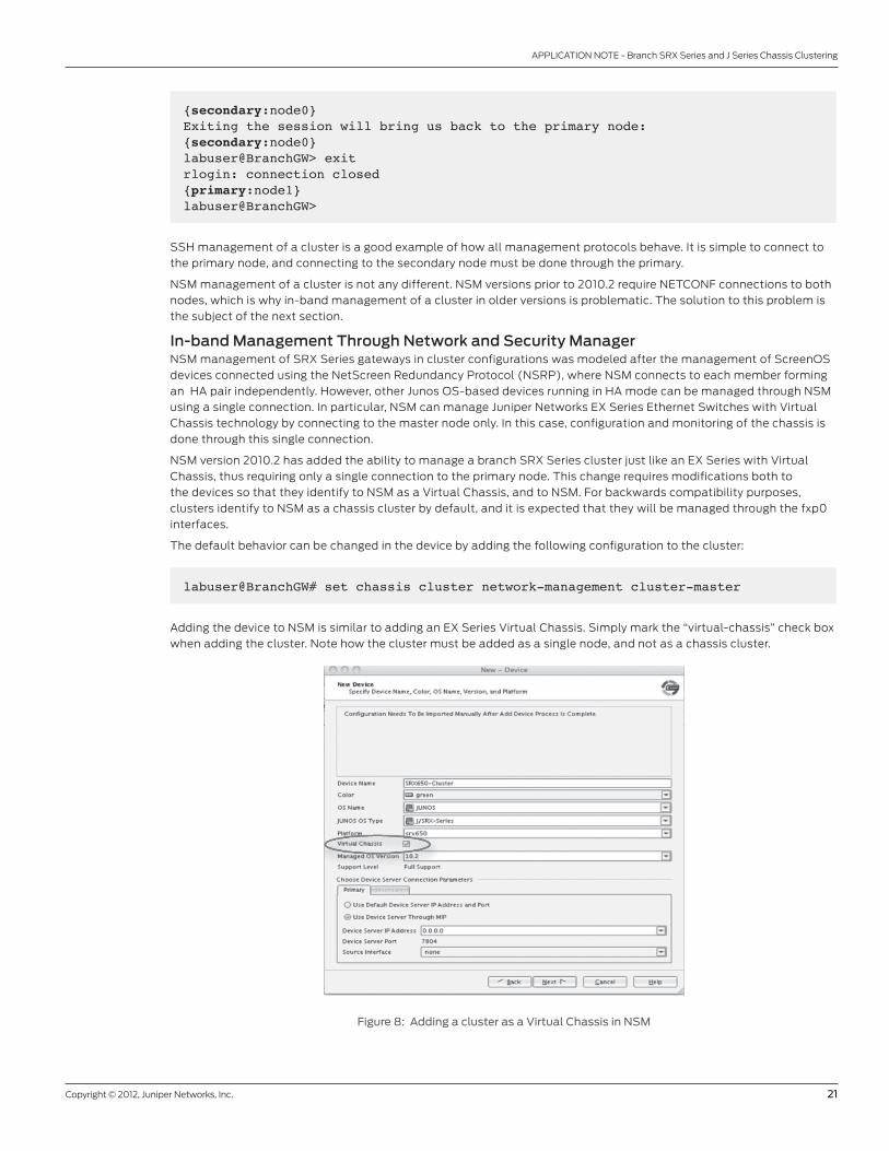
Adding the device to NSM is similar to adding an EX Series Virtual Chassis. Simply mark the “virtual-chassis” check box
when adding the cluster. Note how the cluster must be added as a single node, and not as a chassis cluster.
Figure 8: Adding a cluster as a Virtual Chassis in NSM
22 Copyright © 2012, Juniper Networks, Inc.
APPLICATION NOTE - Branch SRX Series and J Series Chassis Clustering
The hardware inventory will display the chassis serial number of the primary node, and a failover will result in an
update reflecting the serial number change.
Most configuration and monitoring options are supported, with the following exceptions (which will be addressed in a
subsequent release):
• Chassis inventory displays “sub-component” instead of “FPC.”
• The “chassis serial number” as obtained from cached copy in NSM from “get-system-information” contains old
information and is not correct.
• Software update of both devices through NSM is not supported.
• The Virtual Chassis status view shows no valid information.
• License inventory shows information only about primary node.
• Hardware inventory gets out of sync when the primary node is rebooted.
• Reboot commands sent through NSM are only applied on the primary node.
• Only control plane logs from the primary node are sent to NSM.
• Data plane logs (like session logs, IDP attacks, etc) can be sent from both nodes directly to NSM in structured-syslog
format. Support for structured-syslog messages on NSM requires version 2010.4R2 or later.
When updating IDP signatures, NSM pushes the security package to the primary node, after which it sends a remote
procedure call (RPC) to the cluster to trigger an upgrade. Under normal circumstances, only the primary node will get
updated. To overcome this limitation, a Junos OS script has been developed that takes care of updating the secondary
node automatically, after the primary has been updated.
Updating the IDP SignaturesWhen a chassis cluster is managed through an in-band connection, only the control plane of the primary node will have
connectivity to other devices. In particular, only the primary node is able to download new security packages from the
update servers.
The “request security idp security-package download node primary” and the “request security idp security-package
install node primary” commands can still be used to download and install the security package in the primary node
(using these commands without specifying the node will still work on the primary, but fail on the secondary node).
A cluster can automatically copy and install a new installed security package in the secondary, by loading and enabling
the “idp-update.xslt” event script. The script (which can be downloaded from the following location: https://matrix.juniper.net/community/products/security/srxseries/blog/2010/06/01/updating-the-idp-security-package-in-a-cluster-with-no-fxp0-access-to-the-internet) must be copied to the “/var/db/scripts/event” directory in both nodes,
after which it must be enabled using the following configuration:
set event-options policy idp-update events IDP_SECURITY_INSTALL_RESULTset event-options policy idp-update attributes-match idp_security_install_result.status matches successfulset event-options policy idp-update then event-script idp-update.xslt
With the script enabled, all IDP signature update methods are supported, including NSM, command-line interface
(CLI), and auto-update.
It is possible to manually synchronize the signature packages between the nodes by manually copying the contents
of the /var/db/idpd/sec-download directory in the primary node to the secondary. Files can be copied between
nodes by using the “file copy” command and specifying the backup node as the target (file copy /var/db/idpd/sec-
download/<filename> nodeX:/var/db/idpd/sec-download) where nodeX is either node0 or node1, depending on which
node is the backup.
Similarly, the IDP policy templates can be synchronized by simply copying the templates stored in the /var/db/scripts/
commit directory to the secondary node.
Using SNMPJust like in the SSH/Telnet case, the primary device can answer SNMP queries and generate SNMP traps for both
nodes. At the time of this writing, not all MIBs supported by branch SRX Series devices work across a cluster, but most
MIBs do.

Copyright © 2012, Juniper Networks, Inc. 23
APPLICATION NOTE - Branch SRX Series and J Series Chassis Clustering
As an example, querying the interface description of a cluster returns the list of interfaces in both nodes:
[labuser@centos-1 ~]$ snmpwalk -v 2c -c public 10.1.1.34 ifDescrIF-MIB::ifDescr.1 = STRING: fxp0IF-MIB::ifDescr.2 = STRING: fxp1IF-MIB::ifDescr.4 = STRING: lsiIF-MIB::ifDescr.5 = STRING: dscIF-MIB::ifDescr.6 = STRING: lo0IF-MIB::ifDescr.7 = STRING: tapIF-MIB::ifDescr.8 = STRING: greIF-MIB::ifDescr.9 = STRING: ipipIF-MIB::ifDescr.10 = STRING: pimeIF-MIB::ifDescr.11 = STRING: pimdIF-MIB::ifDescr.12 = STRING: mtunIF-MIB::ifDescr.13 = STRING: fxp0.0IF-MIB::ifDescr.14 = STRING: fxp1.0IF-MIB::ifDescr.21 = STRING: lo0.16384IF-MIB::ifDescr.22 = STRING: lo0.16385IF-MIB::ifDescr.116 = STRING: pp0IF-MIB::ifDescr.123 = STRING: st0IF-MIB::ifDescr.159 = STRING: reth1.0IF-MIB::ifDescr.160 = STRING: reth0.0IF-MIB::ifDescr.162 = STRING: reth0IF-MIB::ifDescr.163 = STRING: reth1IF-MIB::ifDescr.172 = STRING: vlanIF-MIB::ifDescr.501 = STRING: ge-0/0/0IF-MIB::ifDescr.502 = STRING: ge-0/0/1IF-MIB::ifDescr.503 = STRING: ge-0/0/1.0IF-MIB::ifDescr.504 = STRING: ge-3/0/0IF-MIB::ifDescr.505 = STRING: ge-3/0/0.0IF-MIB::ifDescr.506 = STRING: ge-3/0/1IF-MIB::ifDescr.507 = STRING: ge-3/0/1.0IF-MIB::ifDescr.508 = STRING: ge-3/0/2IF-MIB::ifDescr.509 = STRING: ge-3/0/3IF-MIB::ifDescr.510 = STRING: ge-3/0/4IF-MIB::ifDescr.511 = STRING: ge-3/0/5IF-MIB::ifDescr.512 = STRING: ge-3/0/6IF-MIB::ifDescr.513 = STRING: ge-3/0/7IF-MIB::ifDescr.514 = STRING: fab1.0IF-MIB::ifDescr.515 = STRING: fab1IF-MIB::ifDescr.516 = STRING: ge-4/0/0IF-MIB::ifDescr.517 = STRING: ge-4/0/1IF-MIB::ifDescr.518 = STRING: ge-4/0/1.0IF-MIB::ifDescr.519 = STRING: ge-7/0/0IF-MIB::ifDescr.520 = STRING: ge-7/0/1IF-MIB::ifDescr.521 = STRING: ge-7/0/0.0IF-MIB::ifDescr.522 = STRING: ge-7/0/2IF-MIB::ifDescr.523 = STRING: ge-7/0/3IF-MIB::ifDescr.524 = STRING: ge-7/0/4IF-MIB::ifDescr.525 = STRING: ge-7/0/5IF-MIB::ifDescr.526 = STRING: ge-7/0/1.0IF-MIB::ifDescr.527 = STRING: ge-7/0/6IF-MIB::ifDescr.528 = STRING: ge-7/0/7IF-MIB::ifDescr.529 = STRING: t1-6/0/0IF-MIB::ifDescr.530 = STRING: t1-6/0/1IF-MIB::ifDescr.531 = STRING: fab0IF-MIB::ifDescr.532 = STRING: fab0.0

24 Copyright © 2012, Juniper Networks, Inc.
APPLICATION NOTE - Branch SRX Series and J Series Chassis Clustering
Software UpgradesJunos OS can be upgraded by connecting to each node individually and executing the “request system software add”
command. The image can be copied to the primary node using FTP or SCP (provided that FTP or SSH are enabled).
Once the image is copied to the primary node, the “file copy” command can be used to copy the file into the secondary
node. The following procedure details how to upgrade both nodes of a cluster managed in-band (the examples were
done in a J Series cluster, but the procedure and commands are the same in both branch SRX Series and J Series
clusters):
1. Copy the software image into the primary node using your preferred method (in this example, the file is stored in /
var/tmp).
2. Copy the files from primary to backup node using the file copy command (it might take a few minutes; in this
example the image was copied to the /var/tmp directory in node0).
labuser@J2320-1# run file copy /var/tmp/junos-jsr-10.2R1.3-domestic.tgz node1:/var/tmp
3. Login to the backup node and load the new image.
labuser@J2320-1# run request routing-engine login node 1 --- JUNOS 10.1-20100515.0 built 2010-05-15 06:07:46 UTC{secondary:node1}labuser@J2320-2> request system software add /var/tmp/junos-jsr-10.2R1.3-domestic.tgz no-copy unlink NOTICE: Validating configuration against junos-jsr-10.2R1.3-domestic.tgz.NOTICE: Use the ‘no-validate’ option to skip this if desired.Checking compatibility with configurationInitializing...Verified manifest signed by PackageProduction_10_1_0Verified junos-10.1-20100515.0-domestic signed by PackageProduction_10_1_0Using /var/tmp/junos-jsr-10.2R1.3-domestic.tgzChecking junos requirements on /Saving boot file package in /var/sw/pkg/junos-boot-jsr-10.2R1.3.tgzVerified manifest signed by PackageProduction_10_2_0Hardware Database regeneration succeededValidating against /config/juniper.conf.gzcp: /cf/var/validate/chroot/var/etc/resolv.conf and /etc/resolv.conf are identical (not copied).cp: /cf/var/validate/chroot/var/etc/hosts and /etc/hosts are identical (not copied).Network security daemon: warning: You have enabled/disabled inet6 flow.Network security daemon: You must reboot the system for your change to take effect.Network security daemon: If you have deployed a cluster, be sure to reboot all nodes.mgd: commit completeValidation succeededValidating against /config/rescue.conf.gzNetwork security daemon: warning: You have enabled/disabled inet6 flow.Network security daemon: You must reboot the system for your change to take effect.Network security daemon: If you have deployed a cluster, be sure to reboot all nodes.

Copyright © 2012, Juniper Networks, Inc. 25
APPLICATION NOTE - Branch SRX Series and J Series Chassis Clustering
mgd: commit completeValidation succeededInstalling package ‘/var/tmp/junos-jsr-10.2R1.3-domestic.tgz’ ...Verified junos-boot-jsr-10.2R1.3.tgz signed by PackageProduction_10_2_0Verified junos-jsr-10.2R1.3-domestic signed by PackageProduction_10_2_0Available space: 333778 require: 4160Saving boot file package in /var/sw/pkg/junos-boot-jsr-10.2R1.3.tgzJUNOS 10.2R1.3 will become active at next rebootWARNING: A reboot is required to load this software correctlyWARNING: Use the ‘request system reboot’ commandWARNING: when software installation is completeSaving state for rollback ...Removing /var/tmp/junos-jsr-10.2R1.3-domestic.tgz{secondary:node1}labuser@J2320-2> exit
4. Upgrade the primary node.
labuser@J2320-1# run request system software add /var/tmp/junos-jsr-10.2R1.3-domestic.tgz no-copy unlink NOTICE: Validating configuration against junos-jsr-10.2R1.3-domestic.tgz.NOTICE: Use the ‘no-validate’ option to skip this if desired.Checking compatibility with configurationInitializing...Verified manifest signed by PackageProduction_10_1_0Verified junos-10.1-20100515.0-domestic signed by PackageProduction_10_1_0Using /var/tmp/junos-jsr-10.2R1.3-domestic.tgzChecking junos requirements on /Saving boot file package in /var/sw/pkg/junos-boot-jsr-10.2R1.3.tgzVerified manifest signed by PackageProduction_10_2_0Hardware Database regeneration succeededValidating against /config/juniper.conf.gzcp: /cf/var/validate/chroot/var/etc/resolv.conf and /etc/resolv.conf are identical (not copied).cp: /cf/var/validate/chroot/var/etc/hosts and /etc/hosts are identical (not copied).Network security daemon: warning: You have enabled/disabled inet6 flow.Network security daemon: You must reboot the system for your change to take effect.Network security daemon: If you have deployed a cluster, be sure to reboot all nodes.mgd: commit completeValidation succeededValidating against /config/rescue.conf.gzmgd: commit completeValidation succeededInstalling package ‘/var/tmp/junos-jsr-10.2R1.3-domestic.tgz’ ...

26 Copyright © 2012, Juniper Networks, Inc.
APPLICATION NOTE - Branch SRX Series and J Series Chassis Clustering
Verified junos-boot-jsr-10.2R1.3.tgz signed by PackageProduction_10_2_0Verified junos-jsr-10.2R1.3-domestic signed by PackageProduction_10_2_0Available space: 332709 require: 4160Saving boot file package in /var/sw/pkg/junos-boot-jsr-10.2R1.3.tgzJUNOS 10.2R1.3 will become active at next rebootWARNING: A reboot is required to load this software correctlyWARNING: Use the ‘request system reboot’ commandWARNING: when software installation is completeSaving state for rollback ...Removing /var/tmp/junos-jsr-10.2R1.3-domestic.tgz
{primary:node0}[edit]labuser@J2320-1#
5. Reboot both nodes.
labuser@J2320-1# run request routing-engine login node 1 --- JUNOS 10.1-20100515.0 built 2010-05-15 06:07:46 UTC{secondary:node1}labuser@J2320-2> request system reboot Reboot the system ? [yes,no] (no) yes
Shutdown NOW![pid 6456]
{secondary:node1}labuser@J2320-2> *** FINAL System shutdown message from labuser@J2320-2 *** System going down IMMEDIATELY {secondary:node1}labuser@J2320-2> exit
rlogin: connection closed
{primary:node0}[edit]labuser@J2320-1# run request system reboot Reboot the system ? [yes,no] (no) yes
Shutdown NOW![pid 7048]
{primary:node0}[edit]labuser@J2320-1# *** FINAL System shutdown message from labuser@J2320-1 *** System going down IMMEDIATELY
Once both nodes are rebooted, the cluster will restart with the new image.

Copyright © 2012, Juniper Networks, Inc. 27
APPLICATION NOTE - Branch SRX Series and J Series Chassis Clustering
3500132-003-EN Feb 2012
Copyright 2012 Juniper Networks, Inc. All rights reserved. Juniper Networks, the Juniper Networks logo, Junos, NetScreen, and ScreenOS are registered trademarks of Juniper Networks, Inc. in the United States and other countries. All other trademarks, service marks, registered marks, or registered service marks are the property of their respective owners. Juniper Networks assumes no responsibility for any inaccuracies in this document. Juniper Networks reserves the right to change, modify, transfer, or otherwise revise this publication without notice.
EMEA Headquarters
Juniper Networks Ireland
Airside Business Park
Swords, County Dublin, Ireland
Phone: 35.31.8903.600
EMEA Sales: 00800.4586.4737
Fax: 35.31.8903.601
APAC Headquarters
Juniper Networks (Hong Kong)
26/F, Cityplaza One
1111 King’s Road
Taikoo Shing, Hong Kong
Phone: 852.2332.3636
Fax: 852.2574.7803
Corporate and Sales Headquarters
Juniper Networks, Inc.
1194 North Mathilda Avenue
Sunnyvale, CA 94089 USA
Phone: 888.JUNIPER (888.586.4737)
or 408.745.2000
Fax: 408.745.2100
www.juniper.net
To purchase Juniper Networks solutions,
please contact your Juniper Networks
representative at 1-866-298-6428 or
authorized reseller.
Printed on recycled paper
SummaryThe branch SRX Series services gateways and J Series chassis cluster is a simple feature to implement that ensures
reliable enterprise connectivity between branch sites and corporate headquarters or regional offices. It provides stateful
traffic failover between two Juniper security devices while maintaining the abstraction of a single device, which simplifies
network design. The feature has been carefully designed to address many common connectivity challenges such as
asymmetric traffic, VPNs, and mixed LAN/WAN environments. Juniper Networks SRX Series for the branch and J Series
Services Routers employing chassis cluster provide a foundation for reliable and high-performance network deployments.
About Juniper NetworksJuniper Networks is in the business of network innovation. From devices to data centers, from consumers to cloud
providers, Juniper Networks delivers the software, silicon and systems that transform the experience and economics of
networking. The company serves customers and partners worldwide. Additional information can be found at
www.juniper.net.
Top Related