


Languages
Pages
Legal

BM-DALI Controller Control Scenarios

www.dalicontrol.com -i- CONTENTS
ContentsBM-DALI CONTROLLER ..............................................................................1
Factory Default Settings.................................................................................... 2 Timers ............................................................................................................ 2 Inputs ............................................................................................................ 3 Input Profiles................................................................................................... 3 Sequences ...................................................................................................... 4 Light Levels..................................................................................................... 6
INPUT CONTROL.......................................................................................7 Input Types..................................................................................................... 7 Override Sequences ......................................................................................... 7 ON/OFF Switch ................................................................................................ 8 ON/OFF Toggle Button ...................................................................................... 8 ON/OFF Toggle Button with Override Timer ......................................................... 8 Single Button Dimmer ...................................................................................... 9 2-Button Dimmer ............................................................................................. 9 3-Button Dimmer ............................................................................................10 Automatic Occupancy Control ...........................................................................11 ON/OFF Toggle Button with Occupancy Override .................................................11 Occupancy Control with manual dimming ...........................................................12 Scene Button..................................................................................................13 Multi-Scene Button..........................................................................................13 Entry and Delayed Exit – Courtesy Button ..........................................................14
OFFICES................................................................................................ 16 OFFICE TYPE A – Manual Dimming with After-Hours Override Sequence.................16 OFFICE TYPE B – Automatic Occupancy Control ..................................................17 OFFICE TYPE C – Manual Dimming with Occupancy Sensor Override......................18 OFFICE TYPE D – Automatic Dimming with Occupancy Sensor Override .................19
MEETING ROOMS.................................................................................... 20 SMALL MEETING ROOM – 2-Button Dimmer .......................................................20 PRESENTATION MEETING ROOM.......................................................................21 EXECUTIVE BOARD ROOM – LCD Control Panel...................................................22
OPEN WORKSPACES ............................................................................... 23 OPEN PLAN WORKSPACES – Manual Control with Override Sequence.....................23 OPEN PLAN WORKSPACES – Automatic Occupancy Control...................................24 PARTITIONED WORKSTATIONS – Automatic Daylight Harvesting ..........................25
CORRIDORS AND WALKWAYS .................................................................. 26 CORRIDOR – Scheduled Occupancy and After-Hours Control ................................26 CORRIDOR –Security Input ..............................................................................27
TOILETS ................................................................................................ 28 BREAKOUT ROOM ................................................................................... 29 STORE ROOM......................................................................................... 30 EXTERNAL LIGHTS.................................................................................. 31 CARPARK............................................................................................... 32 EMERGENCY LIGHTS ............................................................................... 33

www.dalicontrol.com -1- BM-DALI CONTROLLER
BM-DALI CONTROLLER The DALI Control lighting control system is a fully integrated scheduler and intelligent control system designed to control lighting, signage and other building systems. The system scales from small self-contained installations to large networked solutions through the use of two International Standards, DALI (Digital Addressable Lighting Interface) and Ethernet. BM-DALI Controller/Gateways feature a real-time clock for scheduling, inputs for switches and sensors and advanced communications capabilities for integration with access control and security panels and computer networks. The BM-DALI Controller/Gateway includes: 1 Real-time clock featuring:
automatic Daylight Saving adjustment automatic Leap Year compensation Sunrise and Sunset events based on location
2 DALI network support 1 Ethernet RJ45 interface 1 Built-in Web Server for status information 100 Schedule Timers 32 Multi-step Sequences 20 Holiday Periods 16 Digital Inputs 2 Input Profiles 2 Digital Outputs

www.dalicontrol.com -2- BM-DALI CONTROLLER
Factory Default Settings Each BM-DALI Controller is supplied with the factory settings listed in the following sections. These settings enable the controller to be used straight out of the box without further configuration. Of course, you can alter the factory settings and add your own settings to configure a custom solution for your project. Controller Details
Site Code: 1000 Controller Number: 1 Description: BM2600-DALI Location: - Network 1 Name: DALI-A Network 2 Name: DALI-B
EthernetIP Address: 10.0.0.50 Subnet Mask: 255.255.255.0 TCP Port: 1001 UDP Port: 1234
If you would like the controllers pre-configured with different settings contact your sales representative. Timers The BM-DALI Controller includes 100 Timers that can be used for scheduled control. The controller is supplied with four timers pre-configured with the settings shown in the table below. For the sake of simplicity these timers are used in the control scenarios in this document. The timers can of course be reconfigured at any time and other timers can be added as required.
Description S M T W T F S H Type Time TIM01 - Sunrise Y Y Y Y Y Y Y Y Sunrise Timer Sunrise TIM02 - Sunset Y Y Y Y Y Y Y Y Sunset Timer Sunset TIM03 – Normal Hours N Y Y Y Y Y N N Custom Timer 8:00AM TIM04 – After Hours N Y Y Y Y Y N N Custom Timer 6:00PM

www.dalicontrol.com -3- BM-DALI CONTROLLER
Inputs In order to provide control straight out of the box inputs on the BM-DALI controller are pre-configured in the factory as single button dimmers. The inputs are pre-configured as follows:
Input Group Input Group IN00 DALI-01 GROUP 1 IN08 DALI-02 GROUP 1 IN01 DALI-01 GROUP 2 IN09 DALI-02 GROUP 2 IN02 DALI-01 GROUP 3 IN10 DALI-02 GROUP 3 IN03 DALI-01 GROUP 4 IN11 DALI-02 GROUP 4 IN04 DALI-01 GROUP 5 IN12 DALI-02 GROUP 5 IN05 DALI-01 GROUP 6 IN13 DALI-02 GROUP 6 IN06 DALI-01 GROUP 7 IN14 DALI-02 GROUP 7 IN07 DALI-01 BROADCAST IN15 DALI-02 BROADCAST
To use the inputs simply connect a push-to-make switch (pushbutton) between the input terminal and ground terminal. i.e. between IN00 and GND for DALI-01 GROUP 1 and between IN08 and GND for DALI-02 GROUP 1. Input Profiles Inputs on the BM-DALI Controller can be configured to behave differently at different times of the day. For example, an input may be configured to switch lights ON and OFF during office hours but after hours it may be configured with a 30 minute override to ensure that lights are not left on by cleaners or people working late. In order to provide this functionality the BM-DALI Controller uses Input Profiles. An Input Profile holds the configuration for all 16 inputs on the controller. When an Input Profile is recalled the inputs are configured with the settings held in the Input Profile. The BM-DALI Controller is supplied with two pre-configured Input Profiles.
Profile Start Timer IP01 – Normal Hours TIM03 – Normal Hours IP02 – After Hours TIM04 – After Hours
Input Profiles can be recalled by the following methods: • Timers
e.g. at the start of normal office hours and the end of normal office hours. • Inputs
e.g. using a keyswitch or linking to the arming/disarming of a security system.

www.dalicontrol.com -4- BM-DALI CONTROLLER
Sequences The BM-DALI Controller is supplied with several sequences for typical tasks already configured. For the sake of simplicity these preconfigured sequences are used in the following control scenarios. The sequences can of course be altered as required and other sequences can be added at any time. The pre-configured sequences are: SEQ01 – Override OFF
Step Number Delay Period Action Step #1 30 minutes OFF
SEQ02 – Override with Warning Step Number Delay Period Action Step #1 25 minutes MINIMUM Step #2 5 minutes OFF
SEQ03 – After-Hours Override Step Number Delay Period Action Step #1 15 minutes MINIMUM Step #2 3 minutes OFF
SEQ04 – Occupancy to Minimum Step Number Delay Period Action Step #1 15 minutes MINIMUM
SEQ05 – Multi-Stepped Override Step Number Delay Period Action Step #1 10 minutes 75% Step #2 10 minutes 50% Step #3 10 minutes 25% Step #4 10 minutes OFF
SEQ06 – Warning Delay Step Number Delay Period Action Step #1 0 minutes MINIMUM Step #2 5 minutes OFF
SEQ07 – Flash Delay Step Number Delay Period Action Step #1 0 minutes MINIMUM Step #2 3 seconds MAXIMUM Step #3 5 minutes OFF

www.dalicontrol.com -5- BM-DALI CONTROLLER
SEQ08 – Occupancy Step Number Delay Period Action Step #1 15 minutes OFF
SEQ09 – Occupancy with Warning Step Number Delay Period Action Step #1 15 minutes MINIMUM Step #2 5 minutes OFF
SEQ10 – Scene List Step Number Delay Period Action Step #1 10 seconds SCENE1 Step #2 10 seconds SCENE2 Step #3 10 seconds SCENE3 Step #4 10 seconds SCENE4

www.dalicontrol.com -6- BM-DALI CONTROLLER
Light Levels In any given area, the ideal level of light must suit the kind of work being done there and how often artificial light is required. Offices may need to be well lit for eight hours per day, meeting rooms for only one or two hours per day. Corridors do not require the same level of light as do work benches where small parts are being assembled. Interiors of a large building require more artificial light than areas close to windows. Standards Associations in many countries define specific lighting levels for a variety of facilities such as schools, offices, hospitals, factories and so on. The following table shows how different internal areas require different light levels according to the Australian and New Zealand Standard AS/NZS 1680.
Area Illumination Level (lux)
General Purpose 240 Office and Administration 320 Computer areas 320 Assembly/Canteen areas 160 Corridors 40 Foyers 160 Toilets 80

www.dalicontrol.com -7- INPUT CONTROL
INPUT CONTROL BM-DALI Controllers provide sixteen digital inputs for the connection of switches, pushbuttons, occupancy sensors and other devices. The inputs are used to provide an occupant with manual lighting control using switches and automatic control using sensors. Input Types The BM-DALI Controller can be configured to react to Inputs in different ways depending on their Input Type setting. The Input Type tells the BM-DALI controller how to respond to a short input signal (known as a short press) and a long input signal (known as a long press). Input Types on BM-DALI controllers include:
• Maintained Switch • Toggle Button (leading edge) • Advanced Toggle (trailing edge) • Dimmer • Sequence Step • Light Level Switch
The following sections provide examples for the different input types. Override Sequences In addition to the functionality provided by the various Input Types the BM-DALI Controller also enables you to configure an override sequence to ensure that lights are not left ON. An override sequence can be a simple OFF command after a delay period or it can include multiple steps (eg. 75%, 50%, 25%, OFF) to enable people time to vacate an area. Override sequences are cancelled with an OFF command and are restarted by any other action. The following sections provide practical examples for of the use of Sequences.

www.dalicontrol.com -8- INPUT CONTROL
ON/OFF Switch One of the most common inputs on any lighting control system is a switch that toggles the state of the lights. The switch turns ON the lights when the switch is made and turns OFF the lights when the switch is cleared. To configure an input as an ON/OFF switch use the following settings: Input Device Input Type Action1 Action2 Action3 Override Switch Maintained
Switch MAXIMUM OFF (None) (None)
This configuration toggles the lights between MAXIMUM and OFF. Note that any actions can be configured for example the MAXIMUM command could be replaced with an Arc Level of 80%. ON/OFF Toggle Button In modern buildings momentary pushbuttons are often used in place of maintained switches because of the increased functionality that can be achieved with a single pushbutton. For example different commands can be sent depending on how long the pushbutton is pressed. The simplest configuration for a pushbutton is as a toggle button that toggles the lights between two states, typically ON and OFF. To create an ON/OFF toggle button configure an input using the following settings: Input Device Input Type Action1 Action2 Action3 Override Pushbutton Toggle Button MAXIMUM OFF (None) (None)
This configuration toggles the lights between MAXIMUM and OFF with each press of the pushbutton. Note that any actions can be configured for example the OFF command could be replaced with a MINIMUM command to create a toggle between MAXIMUM and MINIMUM. ON/OFF Toggle Button with Override Timer There are rooms, for example a storeroom, where you want to ensure that the lights are not left ON indefinitely. This can be achieved by configuring an Override Sequence for an input. To create an ON/OFF button with an override timer use the following settings: Input Device Input Type Action1 Action2 Action3 Override Pushbutton Advanced
Toggle Button MAXIMUM OFF (None) SEQ01 –
Override OFF
Using this configuration the override sequence will be started when the lights are set to MAXIMUM. By default the sequence SEQ01 will set the lights to OFF after 30 minutes if they have not previously been switched OFF with the pushbutton. NOTE: To provide a warning period before the lights are switched OFF use sequence SEQ02. By default this sequence sets the lights to MINIMUM after 25 minutes and OFF 5 minutes later.

www.dalicontrol.com -9- INPUT CONTROL
Single Button Dimmer A single button dimmer consists of a single pushbutton connected to an input. The pushbutton can be used to switch the lights ON and OFF and to dim them UP and DOWN. The input responds differently to a short press of the button and a long press where the button is held down. Short Press: toggles between switching the lights ON and OFF Long Press: toggles between dimming the lights UP and DOWN The first short press switches the lights on to MAXIMUM while a second short press switches them OFF. If the lights are ON holding the button down will dim the lights UP or DOWN, alternating with each long press. To configure an input as a single button dimmer use the following settings: Input Device Input Type Action1 Action2 Action3 Override Pushbutton Dimmer MAXIMUM OFF DOWN (None)
2-Button Dimmer A 2-button dimmer consists of two pushbuttons, one to switch the lights ON and dim the lights UP and one to switch the lights OFF and dim the lights DOWN. The pushbuttons are typically mounted vertically in a single faceplate. Pushbutton 1Short Press: switches the lights on to MAXIMUM Long Press: dims the lights UP Pushbutton 2Short Press: switches the lights OFF Long Press: dims the lights DOWN To create a 2-button dimmer configure two inputs using the following settings: Input Device Input Type Action1 Action2 Action3 Override Pushbutton 1 Action Button (None) MAXIMUM UP (None) Pushbutton 2 Action Button (None) OFF DOWN (None)
As a variation on the 2-Button Dimmer shown above, pushbutton 2 could be configured to bring the lights on to MINIMUM if the lights are OFF. This is achieved with the following settings: Input Device Input Type Action1 Action2 Action3 Override Pushbutton 1 Action Button (None) MAXIMUM UP (None) Pushbutton 2 Advanced
Toggle Button MINIMUM OFF DOWN (None)
Using this configuration pressing either button will bring the lights on when they are off.
www.dalicontrol.com -10- INPUT CONTROL
3-Button Dimmer A 3-button dimmer consists of three pushbuttons as follows:
Pushbutton 1 to switch the lights ON or OFF Pushbutton 2 to dim the lights UP Pushbutton 3 to dim the lights DOWN.
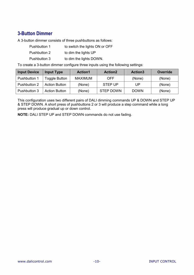
To create a 3-button dimmer configure three inputs using the following settings: Input Device Input Type Action1 Action2 Action3 Override Pushbutton 1 Toggle Button MAXIMUM OFF (None) (None) Pushbutton 2 Action Button (None) STEP UP UP (None) Pushbutton 3 Action Button (None) STEP DOWN DOWN (None)
This configuration uses two different pairs of DALI dimming commands UP & DOWN and STEP UP & STEP DOWN. A short press of pushbuttons 2 or 3 will produce a step command while a long press will produce gradual up or down control. NOTE: DALI STEP UP and STEP DOWN commands do not use fading.

www.dalicontrol.com -11- INPUT CONTROL
Automatic Occupancy Control Automatic occupancy control of your lighting can be achieved by wiring an occupancy sensor to an input on the BM-DALI controller and configuring the input to react to the movement. NOTE: It should be noted that most occupancy sensors provide a normally closed contact so the input on the BM-DALI controller should be configured as an inverted input using the Inverted checkbox. If the sensor is to be used in an office environment it must be sensitive enough to detect the small movements of someone working at a desk. Be sure to place the sensor according to the manufacturer’s instructions and to choose a sensor where the pulse count can be adjusted. If needed multiple sensors can be connected to one input. To configure an input for automatic occupancy control use the following settings: Input Device Input Type Action1 Action2 Action3 Override Occupancy Sensor
Action Button MAXIMUM (None) SEQ02 – Override with
Warning
SEQ02 – Override with
Warning
Using this configuration the lights will be set to MAXIMUM every time the occupancy sensor is triggered. The override sequence is then started. By default the sequence will set the lights to MINIMUM after 25 minutes and then OFF 5 minutes later. If the occupancy sensor is held on or retriggered while the sequence is running the sequence is restarted. NOTE: Occupancy Sensors include a normally—closed (NC) contact so multiple sensors can be wired in series to provide a larger coverage area. ON/OFF Toggle Button with Occupancy Override In order to save power a room may have a pushbutton to turn the lights ON and OFF and an occupancy sensor to ensure that lights do not remain ON when the room is not occupied. To create this functionality configure two inputs using the following settings: Input Device Input Type Action1 Action2 Action3 Override Pushbutton Toggle Button MAXIMUM OFF (None) SEQ01 –
Override OFF Occupancy Sensor
Action Button SEQ01 – Override OFF
(None) SEQ01 – Override OFF
(None)
In this configuration the override sequence will be started when the lights are set to MAXIMUM by the pushbutton. By default the sequence SEQ01 will set the lights to OFF after 30 minutes if they have not previously been switched OFF. NOTE: The override sequence will be restarted every time the occupancy sensor is triggered.

www.dalicontrol.com -12- INPUT CONTROL
Occupancy Control with manual dimming Another variation on the occupancy control theme is to provide automatic on-off control using an occupancy sensor with a separate input for manual dimming. To configure this functionality use two inputs with the following settings: Input Device Input Type Action1 Action2 Action3 Override Occupancy Sensor
Action Button MAXIMUM Only if OFF
(None) (None) SEQ02 – Override with
Warning Pushbutton Dimmer (None) (None) UP SEQ02 –
Override with Warning

www.dalicontrol.com -13- INPUT CONTROL
Scene Button A simple scene button can be created using an input to recall a DALI Scene. Connect a pushbutton to an input and configure it to issue a RECALL SCENE command. To create a Scene button configure an input using the following settings: Input Device Input Type Action1 Action2 Action3 Override Pushbutton Action Button RECALL
SCENE1 (None) (None) (None)
Scene buttons are often used in conference and board rooms where a different scene is required for a meeting, presentation and display. This can be easily achieved with a four button switch plate, where there is one button for each scene and an OFF button. Multi-Scene Button It is also possible to create a single button that steps through a number of predefined scenes. The list of scenes is defined in a Sequence, however instead of running the Sequence a pushbutton is used to step through the list. To create a multi-scene button configure an input using the following settings: Input Device Input Type Action1 Action2 Action3 Override Pushbutton Sequence
Button STEP
FORWARD (None) STEP
FORWARD (None)
In the advanced settings set the Sequence to SEQ10 – Scene List Each time the button is pressed the next scene in the Sequence will be recalled. If the button is held down the scenes will be recalled one after another until the button is released. NOTE: In some projects it may be advantageous to add an OFF command to the sequence. This means that a single button can step through a number of scenes and issue an OFF command thereby providing total control from one input.

www.dalicontrol.com -14- INPUT CONTROL
Entry and Delayed Exit – Courtesy Button A common requirement in lighting control is to provide a delay before the lights are switched OFF. This enables people to find their way out of an area before being plunged into darkness and is used in areas such as carparks and foyers. The task of a pushbutton is to toggle between switching the lights ON and switching the lights OFF after a delay period. To create an Entry/Delayed Exit button configure an input using the following settings: Input Device Input Type Action1 Action2 Action3 Override Pushbutton Toggle Button MAXIMUM SEQ01 –
Override OFF (None) (None)
This configuration provides an instant on to MAXIMUM command to bring the lights ON. When the button is pressed a second time the sequence is started that provides a delay before switching OFF the lights. HINT: A variation on this scenario sets the lights to MINIMUM when the button is pressed a second time and then switches them OFF after the delay period. This can be achieved by adding the MINIMUM command to the beginning of the sequence as in the default SEQ05 –Warning delay. The advantage of this method is that the occupant is provided with immediate visual feedback that they have pressed the button as the light level is dropped to MINIMUM.

-15-

www.dalicontrol.com -16- OFFICES
OFFICES OFFICE TYPE A – Manual Dimming with After-Hours Override Sequence The lights in the Offices are to be controlled according to the following criteria: • In order to provide energy savings the maximum level of the luminaires shall be set to provide
an average maintained illuminance of 320 lux at desk height in accordance with AS/NZS 1680. • A 1-gang switchplate with a momentary pushbutton is to be provided to enable the occupant to
switch the luminaires on and off and to dim the luminaires up and down. This provides the occupant with total control over their office lights.
• To ensure lights do not remain on after-hours when the office is unoccupied, a 30 minute override sequence applies. The lights are to be dimmed to minimum after 25 minutes and switched OFF 5 minutes later if the pushbutton is not pressed.
SOLUTION
OFFICE 1.01
S1.01 Normal Hours OperationInput Device Input Behavior Target Action Dimming Override S1.01 Single Button Dimmer G01 MAX / OFF UP / DOWN - After Hours OperationInput Device Input Behavior Target Action Dimming Override TIM04 After-hours Schedule G01 SEQ02 - - S1.01 Single Button Dimmer G01 MAX / OFF UP / DOWN SEQ02
REMARKS The example solution assumes both office fittings are in Group G01. After hours the override sequence (SEQ02) dims the lights to MINIMUM after 25 minutes and then switches them OFF after another 5 minutes. The override sequence is reset when button S1.01 is pressed.
www.dalicontrol.com -17- OFFICES
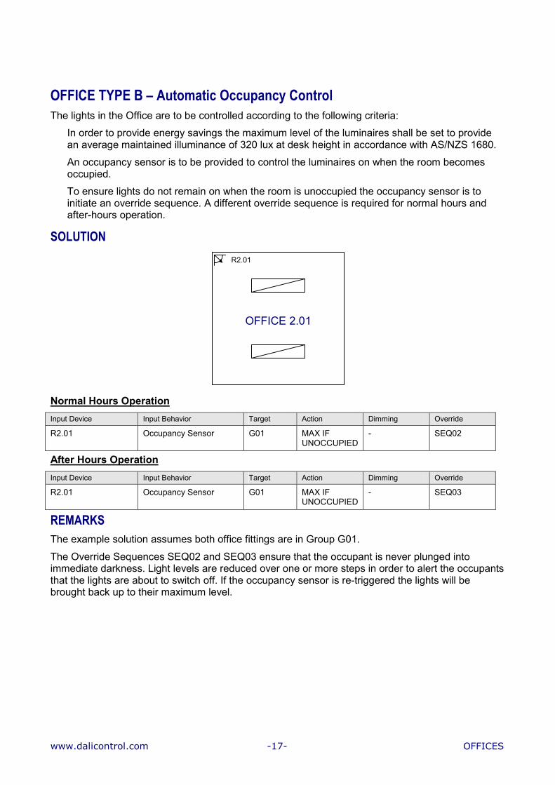
OFFICE TYPE B – Automatic Occupancy Control The lights in the Office are to be controlled according to the following criteria: • In order to provide energy savings the maximum level of the luminaires shall be set to provide
an average maintained illuminance of 320 lux at desk height in accordance with AS/NZS 1680. • An occupancy sensor is to be provided to control the luminaires on when the room becomes
occupied. • To ensure lights do not remain on when the room is unoccupied the occupancy sensor is to
initiate an override sequence. A different override sequence is required for normal hours and after-hours operation.
SOLUTION
OFFICE 2.01
R2.01
Normal Hours OperationInput Device Input Behavior Target Action Dimming Override R2.01 Occupancy Sensor G01 MAX IF
UNOCCUPIED - SEQ02
After Hours OperationInput Device Input Behavior Target Action Dimming Override R2.01 Occupancy Sensor G01 MAX IF
UNOCCUPIED - SEQ03
REMARKS The example solution assumes both office fittings are in Group G01. The Override Sequences SEQ02 and SEQ03 ensure that the occupant is never plunged into immediate darkness. Light levels are reduced over one or more steps in order to alert the occupants that the lights are about to switch off. If the occupancy sensor is re-triggered the lights will be brought back up to their maximum level.

www.dalicontrol.com -18- OFFICES
OFFICE TYPE C – Manual Dimming with Occupancy Sensor Override The lights in the Offices are to be controlled according to the following criteria: • In order to provide energy savings the maximum level of the luminaires shall be set to provide
an average maintained illuminance of 320 lux at desk height in accordance with AS/NZS 1680. • A 1-gang switchplate with a momentary pushbutton is to be provided to enable the occupant to
switch the luminaires on and off and to dim the luminaires up and down. This provides the occupant with total control over their office lights.
• To ensure lights do not remain on when the office is unoccupied an occupancy sensor is to trigger an override sequence. A different override sequence is required for normal hours and after-hours operation.
SOLUTION
OFFICE 2.01
R2.01
S2.01 Normal Hours OperationInput Device Input Behavior Target Action Dimming Override S2.01 Single Button Dimmer G01 MAX / OFF UP / DOWN SEQ02 R2.01 Occupancy Sensor G01 - - SEQ02 After Hours OperationInput Device Input Behavior Target Action Dimming Override S2.01 Single Button Dimmer G01 MAX / OFF UP / DOWN SEQ03 R2.01 Occupancy Sensor G01 - - SEQ03
REMARKS The example solution assumes both office fittings are in Group G01. The lights can automatically be brought ON with the occupancy sensor by adding a MAX action to R2.01. To avoid continually resetting the light level the occupancy sensor should only reset the lights to maximum if the Group is unoccupied.

www.dalicontrol.com -19- OFFICES
OFFICE TYPE D – Automatic Dimming with Occupancy Sensor Override The lights in the Perimeter Offices are to be controlled according to the following criteria: • The Perimeter Offices consist of a mixture of fluorescent troffers and recessed compact
fluorescent fittings. • In order to provide energy savings the maximum level of the luminaires shall be set to provide
an average maintained illuminance of 320 lux at desk height in accordance with AS/NZS 1680. • A 1-gang switchplate with a momentary pushbutton is to be provided to enable the occupant to
switch the luminaires on and off. • Additional energy savings are to be gained with automatic daylight harvesting using the
luminaire with the integral PE cell. • To ensure lights do not remain on when the office is unoccupied an occupancy sensor is to
trigger an override sequence. A different override sequence is required for normal hours and after-hours operation.
SOLUTION R2.20
S2.20
OFFICE 2.20
R
R
PE
Normal Hours OperationInput Device Input Behavior Target Action Dimming Override S2.20 Single Button Dimmer G01 MAX / OFF UP / DOWN SEQ02 R2.20 Occupancy Sensor G01 - - SEQ02 PE2.20 PE Cell G01 - NV01 PE
CELL -
After Hours OperationInput Device Input Behavior Target Action Dimming Override S2.20 Single Button Dimmer G01 MAX / OFF UP / DOWN SEQ03 R2.20 Occupancy Sensor G01 - - SEQ03 PE2.20 PE Cell G01 - NV01 PE
CELL -
REMARKS The example solution assumes all office fittings are in Group G01. The lights can automatically be brought ON with the occupancy sensor by adding a MAX action to R2.20. To avoid continually resetting the light level the occupancy sensor should only reset the lights to maximum if the Group is unoccupied.

www.dalicontrol.com -20- MEETING ROOMS
MEETING ROOMS SMALL MEETING ROOM – 2-Button Dimmer The lights in the Meeting Room are to be controlled according to the following criteria: • A 2-button switchplate with momentary pushbuttons is to be provided to enable occupants to
control the luminaires as designated below. • In order to deliver energy savings Button 1 shall set the luminaires to an arc level that provides
an average maintained illuminance of 240 lux at desk height in accordance with AS/NZS 1680. The level can be dimmed up or down using Buttons 1 and 2.
• To ensure lights do not remain on after-hours when the office is unoccupied, a 30 minute override sequence applies. The lights are to be dimmed to minimum after 25 minutes and switched OFF 5 minutes later if a pushbutton is not pressed.
SOLUTION
MEETING 5.12
S5.1212
S5.12
Normal Hours OperationInput Device Input Behavior Target Action Dimming Override S5.12-1 ON/UP Dimmer G01 MAX UP - S5.12-2 OFF/DOWN Dimmer G01 OFF DOWN - After Hours OperationInput Device Input Behavior Target Action Dimming Override TIM04 After-Hours Schedule G01 SEQ02 - - S5.12-1 ON/UP Dimmer G01 MAX UP SEQ02 S5.12-2 MIN/DOWN Dimmer G01 OFF DOWN SEQ02
REMARKS The example solution assumes all fittings in the room are in Group G01. An override sequence can be easily applied for Normal Hours Operation if required.

www.dalicontrol.com -21- MEETING ROOMS
PRESENTATION MEETING ROOM The lights in the Presentation Meeting Room are to be controlled according to the following criteria: • A 4-button switchplate with momentary pushbuttons is to be provided to enable occupants to
control the luminaires as designated below. • In order to deliver energy savings Button 1 shall set the luminaires to an arc level that provides
an average maintained illuminance of 240 lux at desk height in accordance with AS/NZS 1680. The level can be dimmed up using Button 1 and down using Buttons 2.
• A presentation scene is to be configured where the front luminaires are at 10% and the rear luminaires are at 25%. This provides low light level on the screen while still providing sufficient light on the table. The presentation scene is to be recalled using Button 3.
• Button 4 is to act as an OFF button. • To ensure lights do not remain on when the office is unoccupied an occupancy sensor is to
trigger an override sequence. A different sequence is required for normal hours and after-hours operation.
SOLUTION
MEETING G.30
MG.30
SG.30
Rear Front
1 32 4
SG.30
Normal Hours OperationInput Device Input Behavior Target Action Dimming Override SG.30-1 ON/UP Dimmer G01 MAX UP SEQ02 SG.30-2 MIN/DOWN Dimmer G01 MIN DOWN SEQ02 SG.30-3 Action Button G01 SCN01 - SEQ02 SG.30-4 Action Button G01 OFF - - MG.30 Occupancy Sensor G01 - - SEQ02 After Hours OperationAs per Normal Hours operation except the Override Sequence is SEQ03. REMARKS The example solution assumes all fittings in the room are in Group G01. SCN01 Scene 1 is configured as the presentation scene. Each ballast stores its own level for the scene which means that if required, each light can be at a different level. The lights can automatically be brought on with the occupancy sensor by adding a MAX action for input MG.30. The action should only occur if the Group is unoccupied.
www.dalicontrol.com -22- MEETING ROOMS
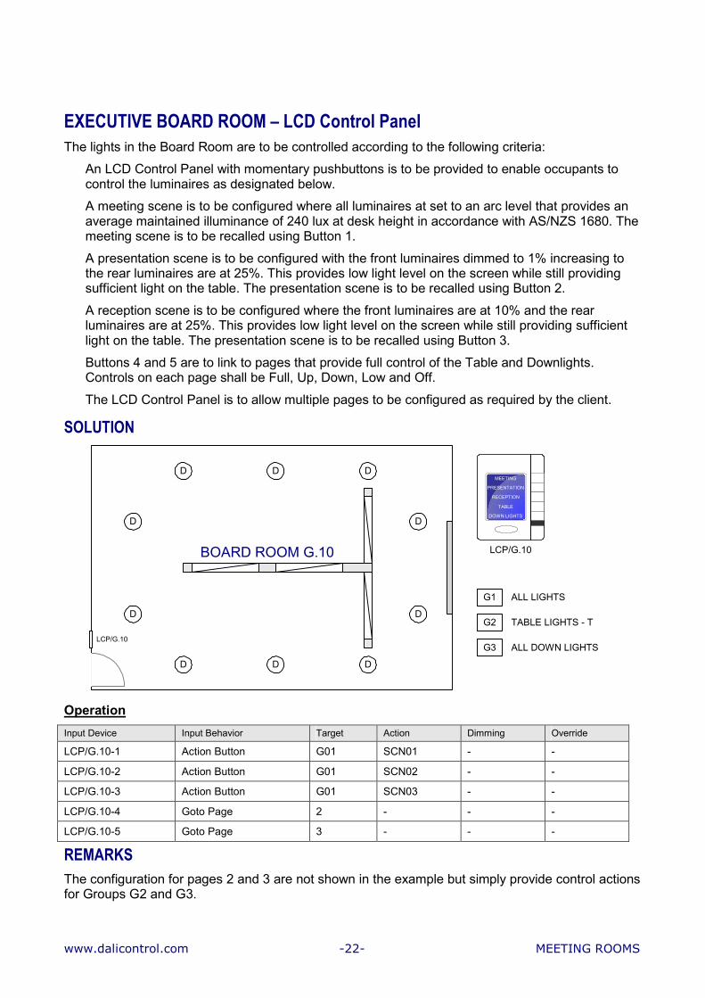
EXECUTIVE BOARD ROOM – LCD Control Panel The lights in the Board Room are to be controlled according to the following criteria: • An LCD Control Panel with momentary pushbuttons is to be provided to enable occupants to
control the luminaires as designated below. • A meeting scene is to be configured where all luminaires at set to an arc level that provides an
average maintained illuminance of 240 lux at desk height in accordance with AS/NZS 1680. The meeting scene is to be recalled using Button 1.
• A presentation scene is to be configured with the front luminaires dimmed to 1% increasing to the rear luminaires are at 25%. This provides low light level on the screen while still providing sufficient light on the table. The presentation scene is to be recalled using Button 2.
• A reception scene is to be configured where the front luminaires are at 10% and the rear luminaires are at 25%. This provides low light level on the screen while still providing sufficient light on the table. The presentation scene is to be recalled using Button 3.
• Buttons 4 and 5 are to link to pages that provide full control of the Table and Downlights. Controls on each page shall be Full, Up, Down, Low and Off.
• The LCD Control Panel is to allow multiple pages to be configured as required by the client. SOLUTION
ALL DOWN LIGHTS
TABLE LIGHTS - T
ALL LIGHTS
BOARD ROOM G.10
LCP/G.10
DDD
DDD
D
D
D
D
G3
G2
G1
MEETINGPRESENTATION
RECEPTIONTABLE
DOWN LIGHTS
LCP/G.10
OperationInput Device Input Behavior Target Action Dimming Override LCP/G.10-1 Action Button G01 SCN01 - - LCP/G.10-2 Action Button G01 SCN02 - - LCP/G.10-3 Action Button G01 SCN03 - - LCP/G.10-4 Goto Page 2 - - - LCP/G.10-5 Goto Page 3 - - -
REMARKS The configuration for pages 2 and 3 are not shown in the example but simply provide control actions for Groups G2 and G3.
www.dalicontrol.com -23- OPEN WORKSPACES
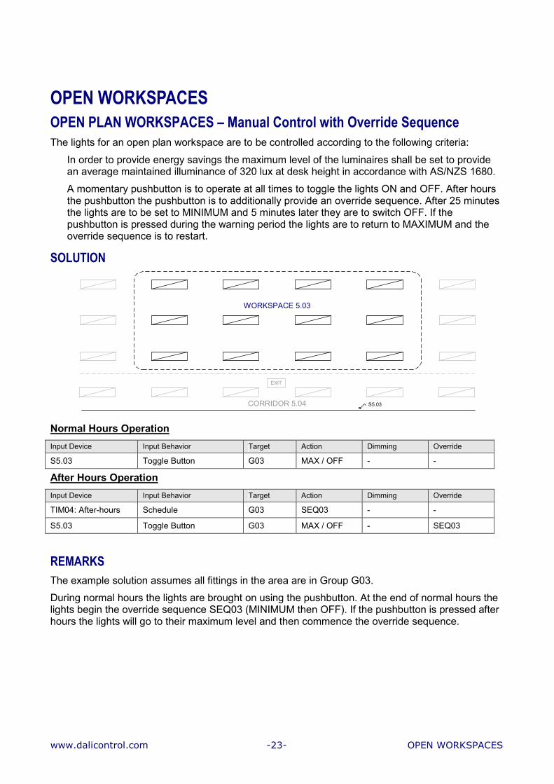
OPEN WORKSPACES OPEN PLAN WORKSPACES – Manual Control with Override Sequence The lights for an open plan workspace are to be controlled according to the following criteria: • In order to provide energy savings the maximum level of the luminaires shall be set to provide
an average maintained illuminance of 320 lux at desk height in accordance with AS/NZS 1680. • A momentary pushbutton is to operate at all times to toggle the lights ON and OFF. After hours
the pushbutton the pushbutton is to additionally provide an override sequence. After 25 minutes the lights are to be set to MINIMUM and 5 minutes later they are to switch OFF. If the pushbutton is pressed during the warning period the lights are to return to MAXIMUM and the override sequence is to restart.
SOLUTION
CORRIDOR 5.04
EXIT
WORKSPACE 5.03
S5.03 Normal Hours OperationInput Device Input Behavior Target Action Dimming Override S5.03 Toggle Button G03 MAX / OFF - - After Hours OperationInput Device Input Behavior Target Action Dimming Override TIM04: After-hours Schedule G03 SEQ03 - - S5.03 Toggle Button G03 MAX / OFF - SEQ03
REMARKS The example solution assumes all fittings in the area are in Group G03. During normal hours the lights are brought on using the pushbutton. At the end of normal hours the lights begin the override sequence SEQ03 (MINIMUM then OFF). If the pushbutton is pressed after hours the lights will go to their maximum level and then commence the override sequence.

www.dalicontrol.com -24- OPEN WORKSPACES
OPEN PLAN WORKSPACES – Automatic Occupancy Control The lights for an open plan workspace are to be controlled according to the following criteria: • In order to provide energy savings the maximum level of the luminaires shall be set to provide
an average maintained illuminance of 320 lux at desk height in accordance with AS/NZS 1680. • An occupancy sensor is to be provided to control the luminaires on when the workspace
becomes occupied. • To ensure lights do not remain on when the workspace is unoccupied the occupancy sensor is
to initiate an override sequence. A different override sequence is required for normal hours and after-hours operation.
SOLUTION
CORRIDOR 5.04
EXIT
WORKSPACE 5.03
M5.03
Normal Hours OperationInput Device Input Behavior Target Action Dimming Override M5.03 Occupancy Sensor G03 MAX IF
UNOCCUPIED- SEQ02
After Hours OperationInput Device Input Behavior Target Action Dimming Override M5.03 Occupancy Sensor G03 MAX IF
UNOCCUPIED - SEQ03
REMARKS The example solution assumes all fittings in the area are in Group G03. The lights are brought on using signal from the PIR sensor. During normal hours override sequence SEQ02 is used while after-hours override sequence SEQ03 is used. The Override Sequences SEQ02 and SEQ03 ensure that the occupant is never plunged into immediate darkness. Light levels are reduced over one or more steps in order to alert the occupants that the lights are about to switch off. If the occupancy sensor is re-triggered the lights will be brought back up to their maximum level.
www.dalicontrol.com -25- OPEN WORKSPACES
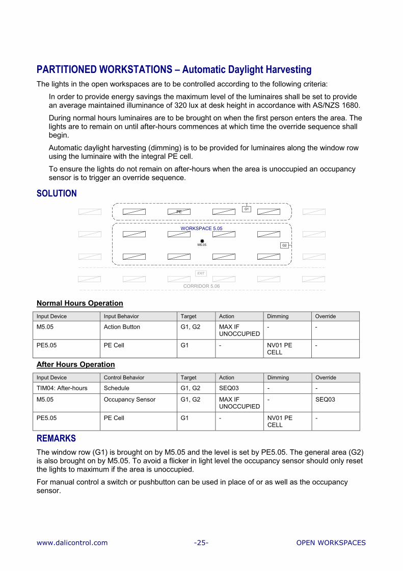
PARTITIONED WORKSTATIONS – Automatic Daylight Harvesting The lights in the open workspaces are to be controlled according to the following criteria: • In order to provide energy savings the maximum level of the luminaires shall be set to provide
an average maintained illuminance of 320 lux at desk height in accordance with AS/NZS 1680. • During normal hours luminaires are to be brought on when the first person enters the area. The
lights are to remain on until after-hours commences at which time the override sequence shall begin.
• Automatic daylight harvesting (dimming) is to be provided for luminaires along the window row using the luminaire with the integral PE cell.
• To ensure the lights do not remain on after-hours when the area is unoccupied an occupancy sensor is to trigger an override sequence.
SOLUTION
CORRIDOR 5.06
EXIT
PE G1
WORKSPACE 5.05
M5.05 G2
Normal Hours OperationInput Device Input Behavior Target Action Dimming Override M5.05 Action Button G1, G2 MAX IF
UNOCCUPIED- -
PE5.05 PE Cell G1 - NV01 PE CELL
-
After Hours OperationInput Device Control Behavior Target Action Dimming Override TIM04: After-hours Schedule G1, G2 SEQ03 - - M5.05 Occupancy Sensor G1, G2 MAX IF
UNOCCUPIED - SEQ03
PE5.05 PE Cell G1 - NV01 PE CELL
-
REMARKS The window row (G1) is brought on by M5.05 and the level is set by PE5.05. The general area (G2) is also brought on by M5.05. To avoid a flicker in light level the occupancy sensor should only reset the lights to maximum if the area is unoccupied. For manual control a switch or pushbutton can be used in place of or as well as the occupancy sensor.

www.dalicontrol.com -26- CORRIDORS AND WALKWAYS
CORRIDORS AND WALKWAYS CORRIDOR – Scheduled Occupancy and After-Hours Control The corridor lights are to be controlled according to the following criteria: • In order to provide energy savings the maximum level of the luminaires shall be set to provide
an average maintained illuminance of 40 lux in accordance with AS/NZS 1680. • During normal hours the lights will be brought on with the arrival of the first person. The lights
will remain on for the duration of the working day. • At the beginning of after-hours the corridor lights will be sequenced OFF. • After-hours the lights are to be brought on by occupancy sensors for a period of 15 minutes. If
no further movement has been detected the lights will then be dimmed to MINIMUM and then five minutes later the lights are to be switched OFF.
SOLUTION
CORRIDOR 5.04
EXIT
WORKSPACE 5.03
M5.04
Normal Hours OperationInput Device Input Behavior Target Action Dimming Override M5.04 Occupancy Sensor G05 MAX IF OFF - - After Hours OperationInput Device Input Behavior Target Action Dimming Override TIM04: After-hours Scheduled Action G05 SEQ03 - - M5.04 Occupancy Sensor G05 MAX IF
UNOCCUPIED - SEQ03
REMARKS The example solution assumes all fittings in the corridor are in Group G05. During normal hours the lights are brought on when occupancy sensor M5.04 first detects movement. At the end of normal hours the lights begin the override sequence SEQ03. If the occupancy sensor is triggered after hours the lights will go to their maximum level and then commence the override sequence. Occupancy sensors should be position to pick up traffic through the area. Multiple sensors can be used if required and can be connected to the same input (refer to wiring diagrams).

www.dalicontrol.com -27- CORRIDORS AND WALKWAYS
CORRIDOR –Security Input The corridor lights are to be controlled according to the following criteria: • In order to provide energy savings the maximum level of the luminaires shall be set to provide
an average maintained illuminance of 40 lux in accordance with AS/NZS 1680. • The lights are to be linked to the security system. • The lights are to be switched ON in the morning when the security system is disarmed and are
to be sequenced OFF in the evening when the security system is armed. • When the security system is armed the lights are to be dimmed to MINIMUM and then five
minutes later the lights are to be switched OFF. If the security system is disarmed during the delay sequence the lights are to return to their MAXIMUM level.
SOLUTION OperationInput Device Input Behavior Target Action Dimming Override SECURITY Maintained switch G05 MAX / SEQ06 - -
REMARKS The example solution assumes all fittings in the corridor are in Group G05. A maintained contact-closure output from the security system is required to indicate when the system is armed and disarmed. The output is ON when the security system is armed. The same technique can be used to link the lights to the lifts.

www.dalicontrol.com -28- TOILETS
TOILETS The lights and fan for the toilets are to be controlled according to the following criteria: • In order to provide energy savings the maximum level of the luminaires shall be set to provide
an average maintained illuminance of 80 lux in accordance with AS/NZS 1680. • The toilet lights are to remain ON at all times during the building’s scheduled occupancy.
(e.g. Weekdays from 8:00AM to 6:00PM.) • At the start of normal hours the lights are to be set to their MINIMUM level and at the end of
normal hours they are to be sequenced OFF provided no-one is using the toilets. If the toilets are occupied at the end of normal hours the lights should be switched OFF when the toilets become unoccupied.
• When the toilets are occupied during normal hours the lights are to be set to MAXIMUM and are to be reset to MINIMUM 15 minutes after no-one is detected in the toilets.
• If the toilets are occupied after hours the lights are to be set to MAXIMUM and are to be reset to MINIMUM 15 minutes after no-one is detected in the toilets and switched OFF 3 minutes later.
• The toilet fan is to operate whenever the lights are on. • Occupancy of the toilets is to be detected using a PIR occupancy sensor. SOLUTION
R
R
R
R
R
R
TOILET 6.46
R6.46
Normal Hours OperationInput Device Input Behavior Target Action Dimming Override R6.46 Occupancy Sensor G06 MAX (80 lux) - SEQ04 After Hours OperationInput Device Input Behavior Target Action Dimming Override R6.46 Occupancy Sensor G06 MAX (80 lux) - SEQ03
REMARKS The aim is to never plunge anyone into darkness in the toilets. Even after hours the lighting is always set to minimum before switching off. The DALI Relay Module used to control the fan should be set so that it is ON when the level is above minimum. Note the toilet lights and the emergency lights are all connected on the same DALI network.

www.dalicontrol.com -29- BREAKOUT ROOM
BREAKOUT ROOM The lights in the breakout rooms are to be controlled according to the following criteria: • In order to provide energy savings the maximum level of the luminaires shall be set to provide
an average maintained illuminance of 160 lux in accordance with AS/NZS 1680. • The fluorescent lights in the room are to be automatically brought on when occupancy is
detected. • To ensure the fluorescent lights do not remain on when the room is unoccupied the occupancy
sensors are to trigger an override sequence. A longer override sequence is required for normal hours than after-hours.
• A 1-gang switchplate with a momentary pushbutton is to be provided to enable the occupant to switch the pendant lights and the bench light on and off. To ensure the lights are not left on the button also triggers an override sequence.
SOLUTION
G2
G1
S9.51
BREAKOUT9.51M9.51A M9.51B
Normal Hours OperationInput Device Input Behavior Target Action Dimming Override S9.51 Single Button Dimmer G2 MAX / OFF UP / DOWN SEQ02 M9.51A+B Occupancy Sensor G1 MAX - SEQ02 After Hours OperationInput Device Input Behavior Target Action Dimming Override S9.51 Single Button Dimmer G2 MAX / OFF UP / DOWN SEQ03 M9.51A+B Occupancy Sensor G1 MAX - SEQ03
REMARKS NOTE: The MAX value is the maximum value in the ballasts which is set to achieve 160 lux.

www.dalicontrol.com -30- STORE ROOM
STORE ROOM The lights in the store room are to be controlled according to the following criteria: • In order to provide energy savings the maximum level of the luminaires shall be set to provide
an average maintained illuminance in accordance with AS/NZS 1680. • A 1-gang switchplate with a momentary pushbutton is to be provided to switch the lights on and
off. To ensure the lights are not left on the button also triggers an override sequence. SOLUTION
STORE 12.07S12.07
OperationInput Device Input Behavior Target Action Dimming Override S12.07 Toggle Button G20* MAX / OFF - SEQ03
REMARKS The store room contains a single light so it is not necessary to create a DALI Group. The store room is controlled using an extended group shown here as G20.

www.dalicontrol.com -31- EXTERNAL LIGHTS
EXTERNAL LIGHTS The external lights for the building are to be controlled according to the following criteria: • The external floodlights are to be switched ON at sunset and OFF at midnight. • The flagpole lights are to be switched ON at sunset and OFF at sunrise. SOLUTION Floodlight OperationInput Device Input Behavior Target Action Dimming Override TIM02: Sunset Schedule G21 ON - - TIM05: Midnight Schedule G21 OFF - -
Flagpole OperationInput Device Input Behavior Target Action Dimming Override TIM02: Sunset Schedule G21 ON - - TIM01: Sunrise Schedule G21 OFF - -
REMARKS The Sunrise and Sunset times are calculated by the system for the location based on the latitude, longitude and time zone of the project. Times can be offset from sunrise and sunset by entering an offset period (minutes) in the sunrise and sunset timers. The external lights can consist of dimmable ballasts or a circuit of fixed output ballasts controlled by a DALI relay module. The solution above uses an extended group.

www.dalicontrol.com -32- CARPARKS
CARPARK The lights on each level of the building’s carpark are to be controlled according to the following criteria: • In order to provide energy savings the maximum level of the luminaires shall be dimmed to
provide an average maintained illuminance in accordance with AS/NZS 1680. • During normal hours the lights on each level of the carpark are to be dimmed to minimum when
no-one is on the level. When a car accesses a level by the ramp or a person accesses a level from the lift the lights are to be brought up to maximum.
• After hours the carpark lights are to be controlled as per normal hours except that the lights are to be switched off at the end of the override sequence.
SOLUTION Normal Hours OperationInput Device Input Behavior Target Action Dimming Override LIFT Occupancy Sensor G16 MAX - SEQ04 RAMP Occupancy Sensor G16 MAX - SEQ04 After Hours OperationInput Device Input Behavior Target Action Dimming Override LIFT Occupancy Sensor G16 MAX - SEQ03 RAMP Occupancy Sensor G16 MAX - SEQ03
REMARKS The carparks are always lit during scheduled occupancy of the building and the system never plunges anyone into immediate darkness. Even after hours the lighting is always set to minimum before switching off.

www.dalicontrol.com -33- EMERGENCY LIGHTS
EMERGENCY LIGHTS The emergency lights comprising emergency halogens, EXIT signs and maintained fittings spread throughout the building are to be controlled according to the following criteria: • All emergency lights in the building are to comply with the DALI Emergency Lighting Standard
and are to be incorporated into the DALI control system. • The system is to report communications failure, battery failure and lamp failure of all emergency
fittings. • The emergency lights are to be tested in accordance with Australian Standard AS 2293.2 REMARKS The International DALI Lighting Control Standard includes the DALI Emergency Standard. This means there is no need to wire an additional system to handle emergency lighting. DALI can report the status of all fittings on the system including emergency lights.
Top Related