


Languages
Pages
Legal

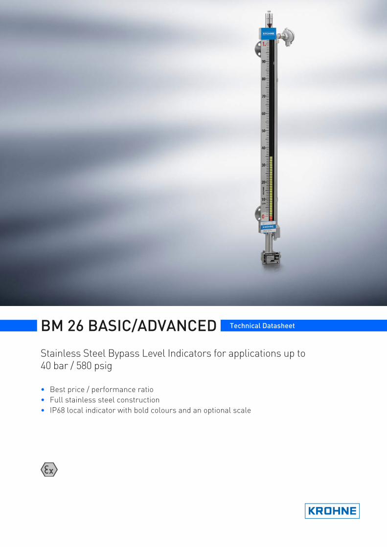
BM 26 BASIC/ADVANCED Technical Datasheet
Stainless Steel Bypass Level Indicators for applications up to 40 bar / 580 psig
• Best price / performance ratio• Full stainless steel construction• IP68 local indicator with bold colours and an optional scale
BM 26 BASIC/ADVANCED nnnnnnnnnnnnnnnnnnnnnnnnnnnnnnnnnnnnn
www.krohne.com 2
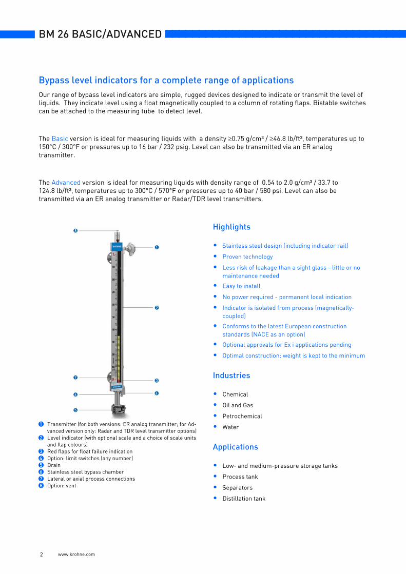
Our range of bypass level indicators are simple, rugged devices designed to indicate or transmit the level of liquids. They indicate level using a float magnetically coupled to a column of rotating flaps. Bistable switches can be attached to the measuring tube to detect level.
The Basic version is ideal for measuring liquids with a density ≥0.75 g/cm³ / ≥46.8 lb/ft³, temperatures up to 150°C / 300°F or pressures up to 16 bar / 232 psig. Level can also be transmitted via an ER analog transmitter.
The Advanced version is ideal for measuring liquids with density range of 0.54 to 2.0 g/cm³ / 33.7 to 124.8 lb/ft³, temperatures up to 300°C / 570°F or pressures up to 40 bar / 580 psi. Level can also be transmitted via an ER analog transmitter or Radar/TDR level transmitters.
Highlights
• Stainless steel design (including indicator rail)
• Proven technology
• Less risk of leakage than a sight glass - little or no maintenance needed
• Easy to install
• No power required - permanent local indication
• Indicator is isolated from process (magnetically-coupled)
• Conforms to the latest European construction standards (NACE as an option)
• Optional approvals for Ex i applications pending
• Optimal construction: weight is kept to the minimum
Industries
• Chemical
• Oil and Gas
• Petrochemical
• Water
Applications
• Low- and medium-pressure storage tanks
• Process tank
• Separators
• Distillation tank
1 Transmitter (for both versions: ER analog transmitter; for Ad-vanced version only: Radar and TDR level transmitter options)
2 Level indicator (with optional scale and a choice of scale units and flap colours)
3 Red flaps for float failure indication4 Option: limit switches (any number)5 Drain6 Stainless steel bypass chamber7 Lateral or axial process connections8 Option: vent
Bypass level indicators for a complete range of applications
nnnnnnnnnnnnnnnnnnnnnnnnnnnnnnnnnnnnn BM 26 BASIC/ADVANCED
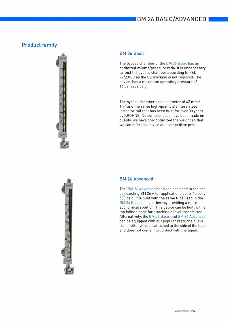
BM 26 Basic
The bypass chamber of the BM 26 Basic has an optimized volume/pressure ratio. It is unnecessary to test the bypass chamber according to PED 97/23/EC as the CE marking is not required. The device has a maximum operating pressure of 16 bar /232 psig.
The bypass chamber has a diameter of 42 mm / 1.7" and the same high-quality stainless steel indicator rail that has been built for over 30 years by KROHNE. No compromises have been made on quality: we have only optimized the weight so that we can offer this device at a competitive price.
BM 26 Advanced
The BM 26 Advanced has been designed to replace our existing BM 26 A for applications up to 40 bar / 580 psig. It is built with the same tube used in the BM 26 Basic design, thereby providing a more economical solution. This device can be built with a top inline flange for attaching a level transmitter. Alternatively, the BM 26 Basic and BM 26 Advanced can be equipped with our popular reed-chain level transmitter which is attached to the side of the tube and does not come into contact with the liquid.
Product family
www.krohne.com 3
BM 26 BASIC/ADVANCED nnnnnnnnnnnnnnnnnnnnnnnnnnnnnnnnnnnnn
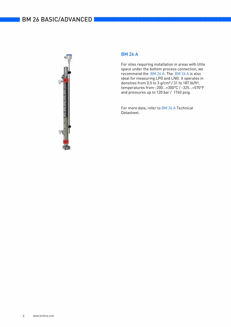
BM 26 A
For sites requiring installation in areas with little space under the bottom process connection, we recommend the BM 26 A. The BM 26 A is also ideal for measuring LPG and LNG. It operates in densities from 0.5 to 3 g/cm³ / 31 to 187 lb/ft³, temperatures from -200...+300°C / -325...+570°F and pressures up to 120 bar / 1740 psig.
For more data, refer to BM 26 A Technical Datasheet.
www.krohne.com 4
nnnnnnnnnnnnnnnnnnnnnnnnnnnnnnnnnnnnn BM 26 BASIC/ADVANCED
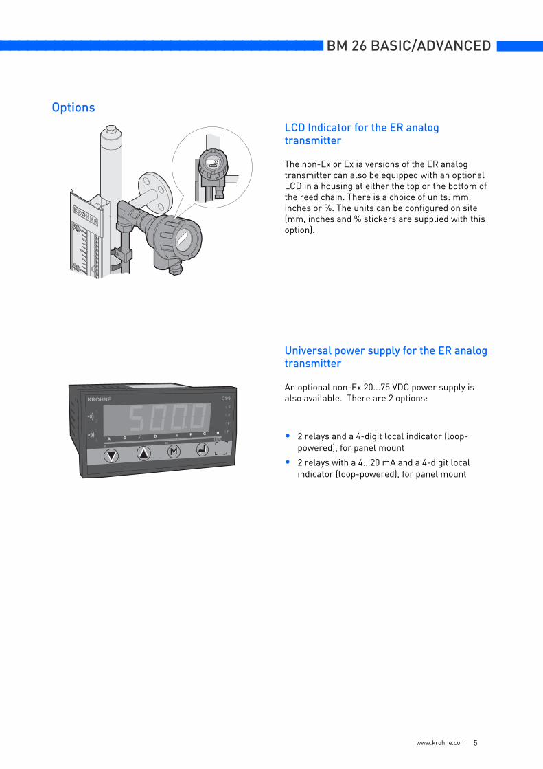
LCD Indicator for the ER analog transmitter
The non-Ex or Ex ia versions of the ER analog transmitter can also be equipped with an optional LCD in a housing at either the top or the bottom of the reed chain. There is a choice of units: mm, inches or %. The units can be configured on site (mm, inches and % stickers are supplied with this option).
Universal power supply for the ER analog transmitter
An optional non-Ex 20...75 VDC power supply is also available. There are 2 options:
• 2 relays and a 4-digit local indicator (loop-powered), for panel mount
• 2 relays with a 4...20 mA and a 4-digit local indicator (loop-powered), for panel mount
33
Options
www.krohne.com 5
BM 26 BASIC/ADVANCED nnnnnnnnnnnnnnnnnnnnnnnnnnnnnnnnnnnnn
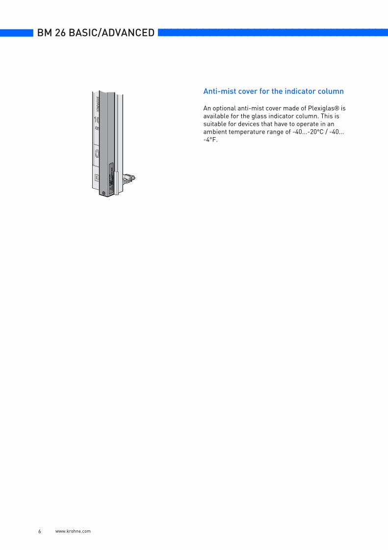
Anti-mist cover for the indicator column
An optional anti-mist cover made of Plexiglas® is available for the glass indicator column. This is suitable for devices that have to operate in an ambient temperature range of -40...-20°C / -40...-4°F.
www.krohne.com 6
nnnnnnnnnnnnnnnnnnnnnnnnnnnnnnnnnnnnn BM 26 BASIC/ADVANCED
www.krohne.com 7
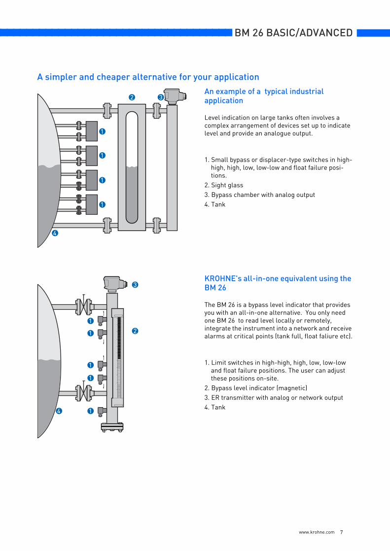
An example of a typical industrial application
Level indication on large tanks often involves acomplex arrangement of devices set up to indicatelevel and provide an analogue output.
1. Small bypass or displacer-type switches in high-high, high, low, low-low and float failure posi-tions.
2. Sight glass3. Bypass chamber with analog output4. Tank
KROHNE's all-in-one equivalent using the BM 26
The BM 26 is a bypass level indicator that provides you with an all-in-one alternative. You only need one BM 26 to read level locally or remotely, integrate the instrument into a network and receive alarms at critical points (tank full, float faliure etc).
1. Limit switches in high-high, high, low, low-low and float failure positions. The user can adjust these positions on-site.
2. Bypass level indicator (magnetic)3. ER transmitter with analog or network output4. Tank
1
1
1
1
2 3
4
4
3
2
1
1
1
1
1
A simpler and cheaper alternative for your application
BM 26 BASIC/ADVANCED nnnnnnnnnnnnnnnnnnnnnnnnnnnnnnnnnnnnn
BM 26 Basic BM 26 Advanced
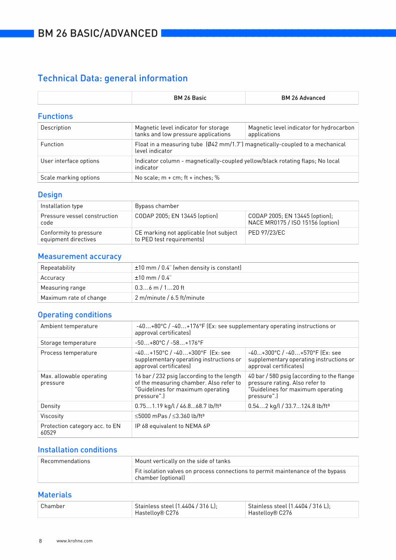
FunctionsDescription Magnetic level indicator for storage
tanks and low pressure applicationsMagnetic level indicator for hydrocarbon applications
Function Float in a measuring tube (Ø42 mm/1.7¨) magnetically-coupled to a mechanical level indicator
User interface options Indicator column - magnetically-coupled yellow/black rotating flaps; No local indicator
Scale marking options No scale; m + cm; ft + inches; %
DesignInstallation type Bypass chamber
Pressure vessel construction code
CODAP 2005; EN 13445 (option) CODAP 2005; EN 13445 (option); NACE MR0175 / ISO 15156 (option)
Conformity to pressure equipment directives
CE marking not applicable (not subject to PED test requirements)
PED 97/23/EC
Measurement accuracyRepeatability ±10 mm / 0.4¨ (when density is constant)
Accuracy ±10 mm / 0.4¨
Measuring range 0.3…6 m / 1…20 ft
Maximum rate of change 2 m/minute / 6.5 ft/minute
Operating conditionsAmbient temperature -40…+80°C / -40…+176°F (Ex: see supplementary operating instructions or
approval certificates)
Storage temperature -50…+80°C / -58…+176°F
Process temperature -40…+150°C / -40…+300°F (Ex: see supplementary operating instructions or approval certificates)
-40...+300°C / -40…+570°F (Ex: see supplementary operating instructions or approval certificates)
Max. allowable operating pressure
16 bar / 232 psig (according to the length of the measuring chamber. Also refer to "Guidelines for maximum operating pressure".)
40 bar / 580 psig (according to the flange pressure rating. Also refer to "Guidelines for maximum operating pressure".)
Density 0.75…1.19 kg/l / 46.8...68.7 lb/ft³ 0.54…2 kg/l / 33.7...124.8 lb/ft³
Viscosity ≤5000 mPas / ≤3.360 lb/ft³
Protection category acc. to EN 60529
IP 68 equivalent to NEMA 6P
Installation conditionsRecommendations Mount vertically on the side of tanks
Fit isolation valves on process connections to permit maintenance of the bypass chamber (optional)
MaterialsChamber Stainless steel (1.4404 / 316 L);
Hastelloy® C276Stainless steel (1.4404 / 316 L); Hastelloy® C276
Technical Data: general information
www.krohne.com 8
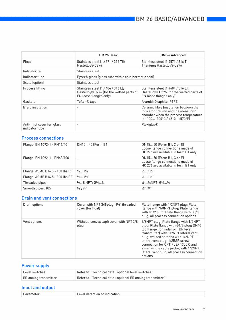
nnnnnnnnnnnnnnnnnnnnnnnnnnnnnnnnnnnnn BM 26 BASIC/ADVANCED
Float Stainless steel (1.4571 / 316 Ti); Hastelloy® C276
Stainless steel (1.4571 / 316 Ti); Titanium; Hastelloy® C276
Indicator rail Stainless steel
Indicator tube Pyrex® glass (glass tube with a true hermetic seal)
Scale (option) Stainless steel
Process fitting Stainless steel (1.4404 / 316 L); Hastelloy® C276 (for the wetted parts of EN loose flanges only)
Stainless steel (1.4404 / 316 L); Hastelloy® C276 (for the wetted parts of EN loose flanges only)
Gaskets Teflon® tape Aramid; Graphite; PTFE
Braid insulation - Ceramic fibre (insulation between the indicator column and the measuring chamber when the process temperature is +100...+300°C / +210...+570°F)
Anti-mist cover for glass indicator tube
- Plexiglas®
Process connectionsFlange, EN 1092-1 - PN16/40 DN15…40 (Form B1) DN15…50 (Form B1, C or E)
Loose flange connections made of HC 276 are available in form B1 only
Flange, EN 1092-1 - PN63/100 - DN15…50 (Form B1, C or E)Loose flange connections made of HC 276 are available in form B1 only
Flange, ASME B16.5 - 150 lbs RF ½…1½¨ ½…1½¨
Flange, ASME B16.5 - 300 lbs RF ½…1½¨ ½…1½¨
Threaded pipes ½...¾NPT; G½...¾ ½…¾NPT; G½...¾
Smooth pipes, 10S ½¨; ¾¨ ½¨; ¾¨
Drain and vent connectionsDrain options Cover with NPT 3/8 plug; 1¼¨ threaded
cover (for float)Plate flange with 1/2NPT plug; Plate flange with 3/8NPT plug; Plate flange with G1/2 plug; Plate flange with G3/8 plug; all process connection options
Vent options Without (convex cap); cover with NPT 3/8 plug
3/8NPT plug; Plate flange with 1/2NPT plug; Plate flange with G1/2 plug; DN40 top flange (for radar or TDR level transmitter) with 1/2NPT lateral vent plug; welded antenna with 1/2NPT lateral vent plug; 1/2BSP screw connection for OPTIFLEX 1300 C and 2 mm single cable probe, with 1/2NPT lateral vent plug; all process connection options
Power supplyLevel switches Refer to "Technical data : optional level switches"
ER analog transmitter Refer to "Technical data : optional ER analog transmitter"
Input and outputParameter Level detection or indication
BM 26 Basic BM 26 Advanced
www.krohne.com 9

BM 26 BASIC/ADVANCED nnnnnnnnnnnnnnnnnnnnnnnnnnnnnnnnnnnnn
Output signal Refer to "Technical data : optional level switches" and "Technical data: optional ER analog transmitter"
ApprovalsATEX (pending) ATEX II 1 G or 1/2 G c IIC T1...T6 (measuring chamber)
Refer also to approvals in "Technical data : optional level switches"
Variants and optionsVariants Lateral / lateral process connections
Axial / axial process connections
Top lateral / Bottom axial process connections
Top axial / Bottom lateral connections
Options ER analog transmitter without display (4-20 mA, 4-20 mA/HART® or PROFIBUS PA/FF converter mounted at the top or bottom of the reed chain)
ER analog transmitter with display (4-20 mA or 4-20 mA/HART ® converter mounted at the top or bottom of the reed chain)
- Anti-mist cover for glass indicator tube (when the ambient temperature is -40...-20°C / -40...-4°F)
- OPTIFLEX 1300 C with 2 mm single cable probe (if 1/2BSP top axial connection is selected)
- OPTIFLEX 1300 C (if DN40 PN40 top axial connection is selected )
- OPTIWAVE 7300 C (if welded antenna or DN40 PN40 top axial connection is selected)
Accessories MS 40 bistable limit switches (NAMUR or non-NAMUR)
BM 26 Basic BM 26 Advanced
www.krohne.com 10
nnnnnnnnnnnnnnnnnnnnnnnnnnnnnnnnnnnnn BM 26 BASIC/ADVANCED
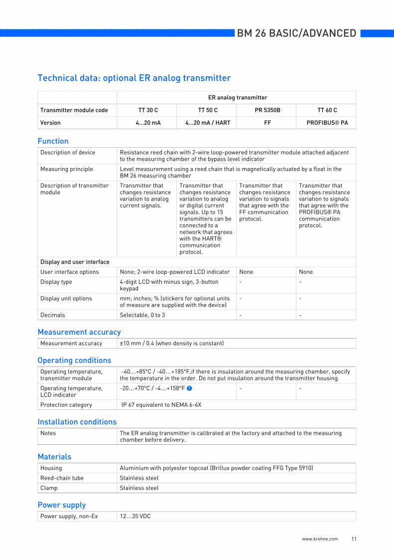
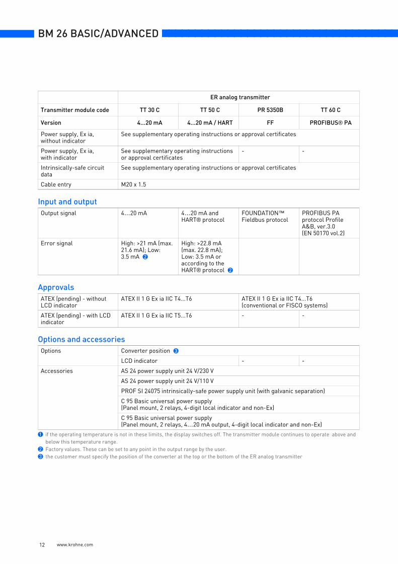
ER analog transmitter
Transmitter module code TT 30 C TT 50 C PR 5350B TT 60 C
Version 4...20 mA 4...20 mA / HART FF PROFIBUS® PA
FunctionDescription of device Resistance reed chain with 2-wire loop-powered transmitter module attached adjacent
to the measuring chamber of the bypass level indicator
Measuring principle Level measurement using a reed chain that is magnetically actuated by a float in the BM 26 measuring chamber
Description of transmitter module
Transmitter that changes resistance variation to analog current signals.
Transmitter that changes resistance variation to analog or digital current signals. Up to 15 transmitters can be connected to a network that agrees with the HART® communication protocol.
Transmitter that changes resistance variation to signals that agree with the FF communication protocol.
Transmitter that changes resistance variation to signals that agree with the PROFIBUS® PA communication protocol.
Display and user interface
User interface options None; 2-wire loop-powered LCD indicator None None
Display type 4-digit LCD with minus sign, 3-button keypad
- -
Display unit options mm; inches; % (stickers for optional units of measure are supplied with the device)
- -
Decimals Selectable, 0 to 3 - -
Measurement accuracyMeasurement accuracy ±10 mm / 0.4 (when density is constant)
Operating conditionsOperating temperature, transmitter module
-40…+85°C / -40…+185°F,if there is insulation around the measuring chamber, specify the temperature in the order. Do not put insulation around the transmitter housing.
Operating temperature, LCD indicator
-20…+70°C / -4…+158°F 1 - -
Protection category IP 67 equivalent to NEMA 6-6X
Installation conditionsNotes The ER analog transmitter is calibrated at the factory and attached to the measuring
chamber before delivery.
MaterialsHousing Aluminium with polyester topcoat (Brillux powder coating FFG Type 5910)
Reed-chain tube Stainless steel
Clamp Stainless steel
Power supplyPower supply, non-Ex 12…35 VDC
Technical data: optional ER analog transmitter
www.krohne.com 11
BM 26 BASIC/ADVANCED nnnnnnnnnnnnnnnnnnnnnnnnnnnnnnnnnnnnn
Power supply, Ex ia,without indicator
See supplementary operating instructions or approval certificates
Power supply, Ex ia,with indicator
See supplementary operating instructions or approval certificates
- -
Intrinsically-safe circuit data
See supplementary operating instructions or approval certificates
Cable entry M20 x 1.5
Input and outputOutput signal 4…20 mA 4…20 mA and
HART® protocolFOUNDATION™ Fieldbus protocol
PROFIBUS PA protocol Profile A&B, ver.3.0 (EN 50170 vol.2)
Error signal High: >21 mA (max. 21.6 mA); Low: 3.5 mA 2
High: >22.8 mA (max. 22.8 mA); Low: 3.5 mA or according to the HART® protocol 2
ApprovalsATEX (pending) - without LCD indicator
ATEX II 1 G Ex ia IIC T4...T6 ATEX II 1 G Ex ia IIC T4...T6(conventional or FISCO systems)
ATEX (pending) - with LCD indicator
ATEX II 1 G Ex ia IIC T5...T6 - -
Options and accessoriesOptions Converter position 3
LCD indicator - -
Accessories AS 24 power supply unit 24 V/230 V
AS 24 power supply unit 24 V/110 V
PROF SI 24075 intrinsically-safe power supply unit (with galvanic separation)
C 95 Basic universal power supply(Panel mount, 2 relays, 4-digit local indicator and non-Ex)
C 95 Basic universal power supply(Panel mount, 2 relays, 4…20 mA output, 4-digit local indicator and non-Ex)
1 if the operating temperature is not in these limits, the display switches off. The transmitter module continues to operate above and below this temperature range.
2 Factory values. These can be set to any point in the output range by the user.3 the customer must specify the position of the converter at the top or the bottom of the ER analog transmitter
ER analog transmitter
Transmitter module code TT 30 C TT 50 C PR 5350B TT 60 C
Version 4...20 mA 4...20 mA / HART FF PROFIBUS® PA
www.krohne.com 12
nnnnnnnnnnnnnnnnnnnnnnnnnnnnnnnnnnnnn BM 26 BASIC/ADVANCED
www.krohne.com 13
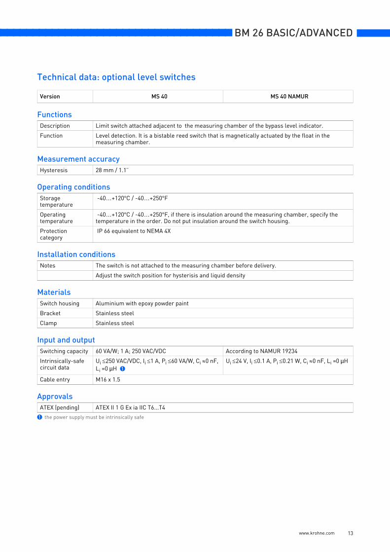
Version MS 40 MS 40 NAMUR
FunctionsDescription Limit switch attached adjacent to the measuring chamber of the bypass level indicator.
Function Level detection. It is a bistable reed switch that is magnetically actuated by the float in the measuring chamber.
Measurement accuracyHysteresis 28 mm / 1.1¨
Operating conditions Storage temperature
-40…+120°C / -40…+250°F
Operating temperature
-40…+120°C / -40…+250°F, if there is insulation around the measuring chamber, specify the temperature in the order. Do not put insulation around the switch housing.
Protection category
IP 66 equivalent to NEMA 4X
Installation conditionsNotes The switch is not attached to the measuring chamber before delivery.
Adjust the switch position for hysterisis and liquid density
MaterialsSwitch housing Aluminium with epoxy powder paint
Bracket Stainless steel
Clamp Stainless steel
Input and outputSwitching capacity 60 VA/W; 1 A; 250 VAC/VDC According to NAMUR 19234
Intrinsically-safe circuit data
Ui ≤250 VAC/VDC, Ii ≤1 A, Pi ≤60 VA/W, Ci ≈0 nF, Li =0 µH 1
Ui ≤24 V, Ii ≤0.1 A, Pi ≤0.21 W, Ci ≈0 nF, Li =0 µH
Cable entry M16 x 1.5
ApprovalsATEX (pending) ATEX II 1 G Ex ia IIC T6...T4
1 the power supply must be intrinsically safe
Technical data: optional level switches
BM 26 BASIC/ADVANCED nnnnnnnnnnnnnnnnnnnnnnnnnnnnnnnnnnnnn
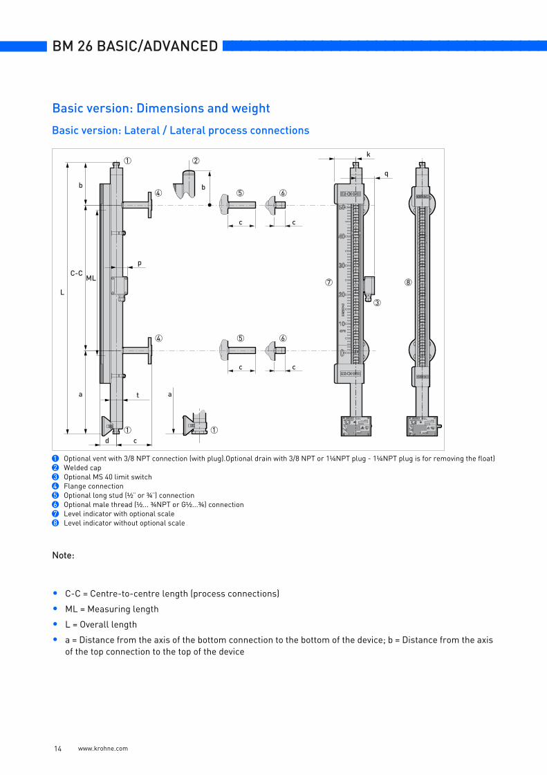
Note:
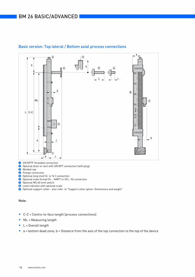
• C-C = Centre-to-centre length (process connections)
• ML = Measuring length
• L = Overall length
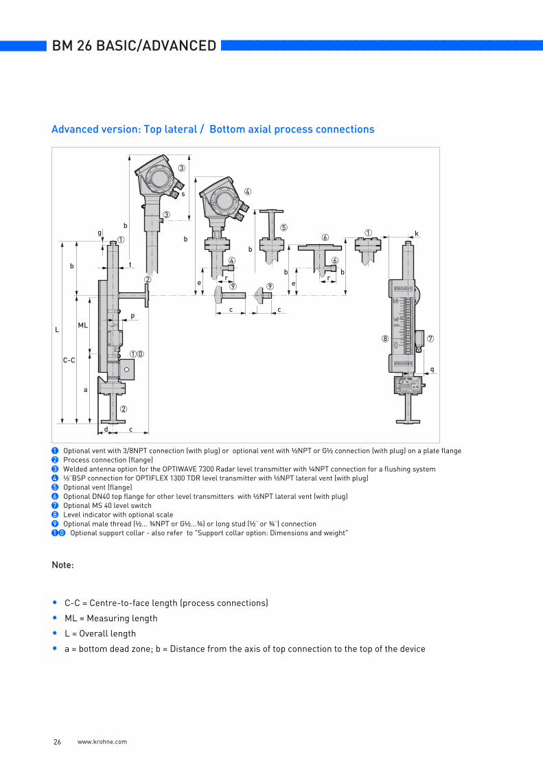
• a = Distance from the axis of the bottom connection to the bottom of the device; b = Distance from the axis of the top connection to the top of the device
Basic version: Lateral / Lateral process connections
1 Optional vent with 3/8 NPT connection (with plug).Optional drain with 3/8 NPT or 1¼NPT plug - 1¼NPT plug is for removing the float)2 Welded cap3 Optional MS 40 limit switch4 Flange connection5 Optional long stud (½¨ or ¾¨) connection6 Optional male thread (½... ¾NPT or G½...¾) connection7 Level indicator with optional scale8 Level indicator without optional scale
C-C
a a
b
L
t
d c
b
c c
c c
ML
1
1 1
2
3
5
6
7 8
5
4
4
6
p
q
k
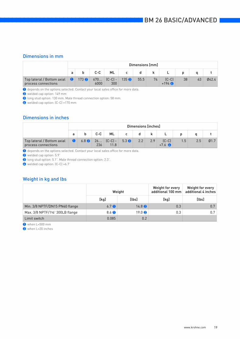
Basic version: Dimensions and weight
www.krohne.com 14
nnnnnnnnnnnnnnnnnnnnnnnnnnnnnnnnnnnnn BM 26 BASIC/ADVANCED
Dimensions in mm
Dimensions in inches
Weight in kg and lbs
Dimensions [mm]
a b C-C ML c d k L p q t
Lateral / Lateralprocess connections
310 1 173 2 300…6000
3 135 4 55.5 74 (C-C)+483 5
38 63 Ø42.4
1 optional drain with 1¼¨ plug: 323 mm2 welded cap option: 149 mm3 this is equal to the dimension C-C4 long stud option: 130 mm. Male thread connection option: 58 mm.5 welded cap option: (C-C) +459 mm. 1¼¨ plug option: (C-C) +500 mm. Welded cap + 1¼¨ plug options: (C-C) +476 mm.
Dimensions [inches]
a b C-C ML c d k L p q t
Lateral / Lateralprocess connections
12.2 1 6.8 2 20…236
3 5.3 4 2.2 2.9 (C-C)+19 5
1.5 2.5 Ø1.7
1 optional drain with 1¼¨ plug: 12.7¨2 welded cap option: 5.9¨3 this is equal to the dimension C-C4 long stud option: 5.1¨. Male thread connection option: 2.3¨.5 welded cap option: (C-C) +18.1¨. 1¼¨ plug option: (C-C) +19.7¨. Welded cap + 1¼¨ plug options: (C-C) +18.7¨.
WeightWeight for every
additional 100 mmWeight for every
additional 4 inches
[kg] [lbs] [kg] [lbs]
Min.: DN15 PN40 flanges 7.4 1 16.3 2 0.3 0.7
Max.: 1½¨ 300LB flanges 11.2 1 24.7 2 0.3 0.7
Limit switch 0.085 0.2
1 when L=500 mm2 when L=20 inches
www.krohne.com 15
BM 26 BASIC/ADVANCED nnnnnnnnnnnnnnnnnnnnnnnnnnnnnnnnnnnnn
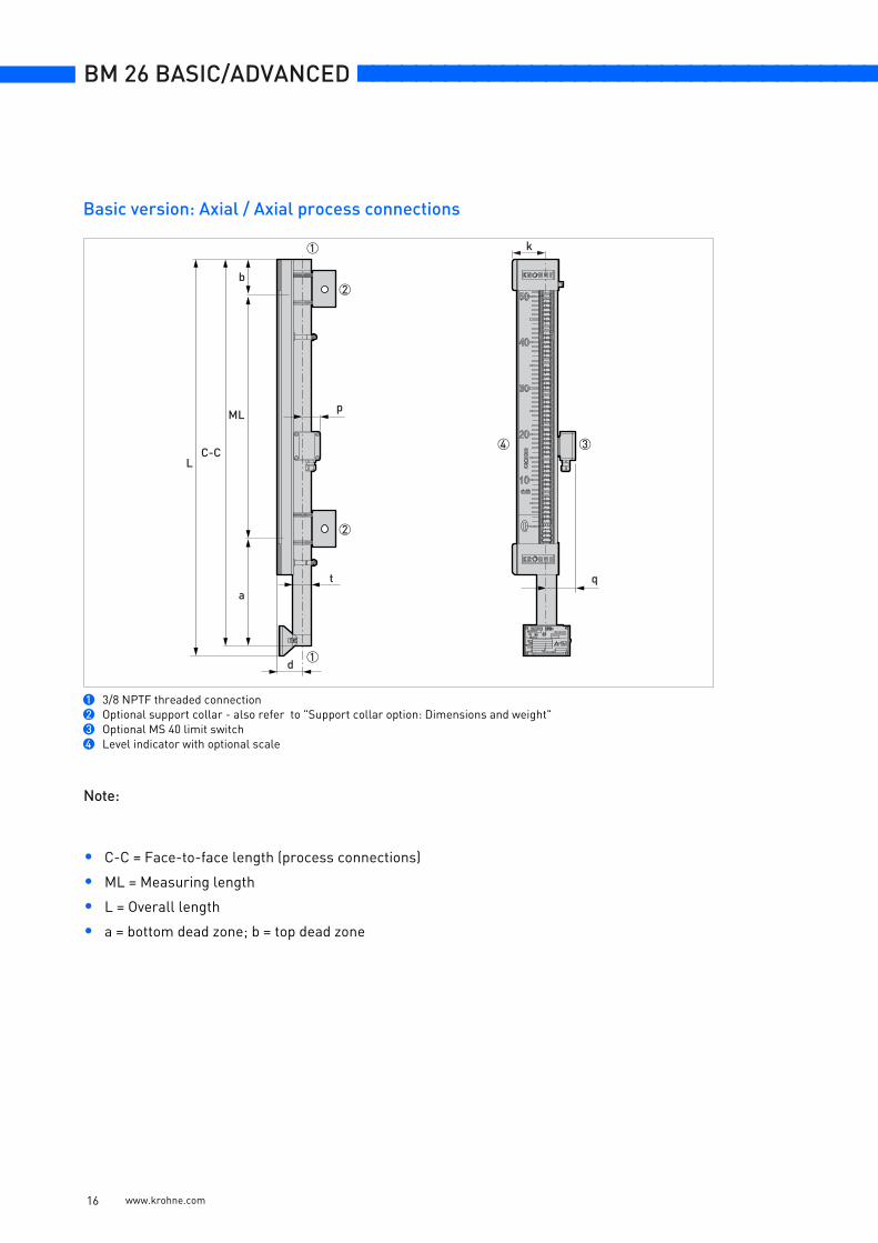
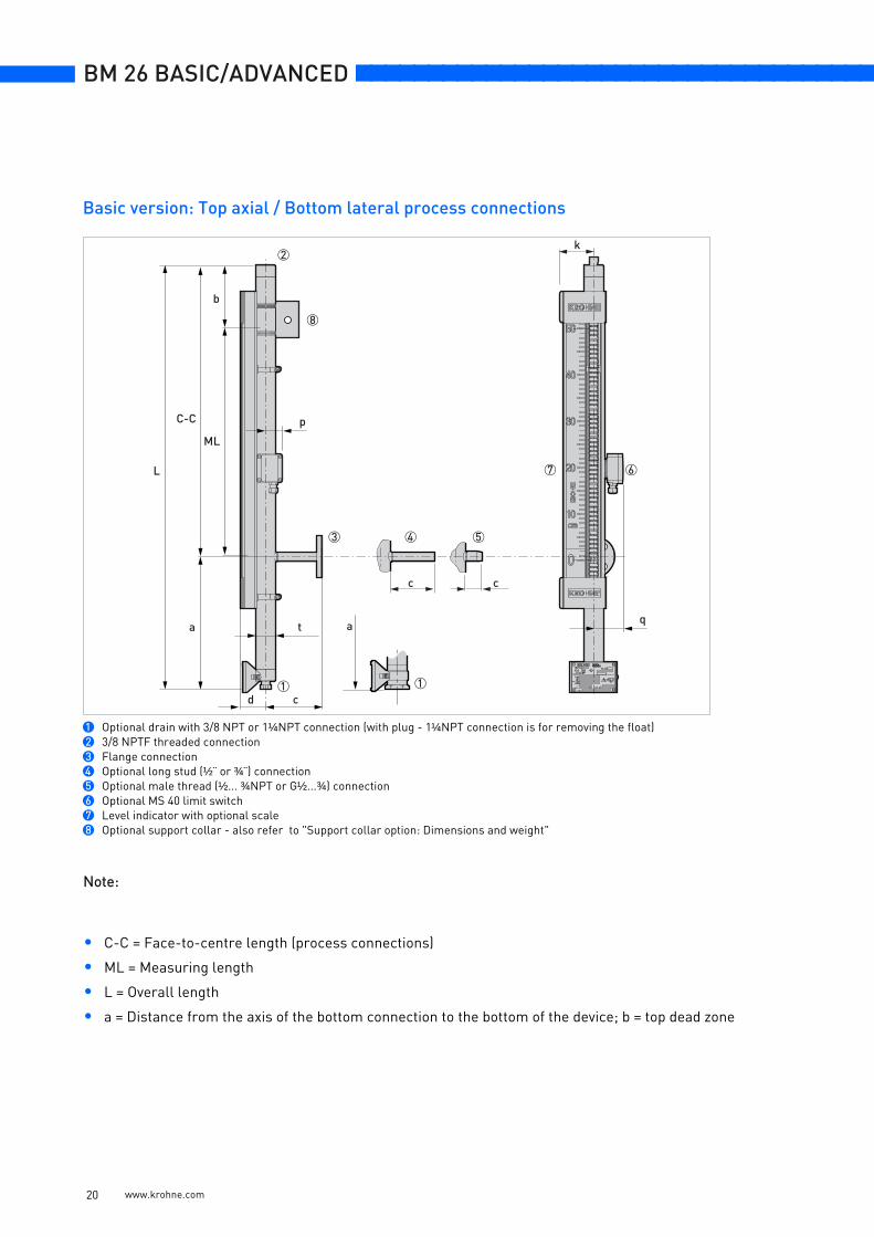
Note:
• C-C = Face-to-face length (process connections)
• ML = Measuring length
• L = Overall length
• a = bottom dead zone; b = top dead zone
Basic version: Axial / Axial process connections
1 3/8 NPTF threaded connection2 Optional support collar - also refer to "Support collar option: Dimensions and weight"3 Optional MS 40 limit switch4 Level indicator with optional scale
C-CL
ML
t
d
a
b
34
1
2
2
1
p
q
k
www.krohne.com 16
nnnnnnnnnnnnnnnnnnnnnnnnnnnnnnnnnnnnn BM 26 BASIC/ADVANCED
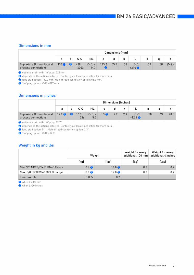
Dimensions in mm
Dimensions in inches
Weight in kg and lbs
Dimensions [mm]
a b C-C ML d k L p q t
Axial / Axialprocess connections
1 1 642…6000
(C-C) -370
55.5 74 (C-C)+21
38 63 Ø42.4
1 depends on the options selected. Contact your local sales office for more data.
Dimensions [inches]
a b C-C ML d k L p q t
Axial / Axialprocess connections
1 1 25…236
(C-C) -14.6
2.5 2.9 (C-C)+0.8
1.5 2.5 Ø1.7
1 depends on the options selected. Contact your local sales office for more data.
WeightWeight for every
additional 100 mmWeight for every
additional 4 inches
[kg] [lbs] [kg] [lbs]
3/8 NPTF 6.0 1 13.2 2 0.3 0.7
Limit switch 0.085 0.2
1 when L=500 mm2 when L=20 inches
www.krohne.com 17
BM 26 BASIC/ADVANCED nnnnnnnnnnnnnnnnnnnnnnnnnnnnnnnnnnnnn
Note:
• C-C = Centre-to-face length (process connections)
• ML = Measuring length
• L = Overall length
• a = bottom dead zone; b = Distance from the axis of the top connection to the top of the device
Basic version: Top lateral / Bottom axial process connections
1 3/8 NPTF threaded connection2 Optional drain or vent with 3/8 NPT connection (with plug)3 Welded cap4 Flange connection5 Optional long stud (½¨ or ¾¨) connection6 Optional male thread (½... ¾NPT or G½...¾) connection7 Optional MS 40 limit switch8 Level indicator with optional scale9 Optional support collar - also refer to "Support collar option: Dimensions and weight"
C-CL
b b
t
d c
c c
ML
k
a
7
8
9
654
2
1
3
p
q
www.krohne.com 18
nnnnnnnnnnnnnnnnnnnnnnnnnnnnnnnnnnnnn BM 26 BASIC/ADVANCED
Dimensions in mm
Dimensions in inches
Weight in kg and lbs
Dimensions [mm]
a b C-C ML c d k L p q t
Top lateral / Bottom axialprocess connections
1 173 2 670…6000
(C-C) -300
135 3 55.5 74 (C-C)+194 4
38 63 Ø42.4
1 depends on the options selected. Contact your local sales office for more data.2 welded cap option: 149 mm3 long stud option: 130 mm. Male thread connection option: 58 mm.4 welded cap option: (C-C) +170 mm
Dimensions [inches]
a b C-C ML c d k L p q t
Top lateral / Bottom axialprocess connections
1 6.8 2 26…236
(C-C) -11.8
5.3 3 2.2 2.9 (C-C)+7.6 4
1.5 2.5 Ø1.7
1 depends on the options selected. Contact your local sales office for more data.2 welded cap option: 5.9¨3 long stud option: 5.1¨. Male thread connection option: 2.3¨.4 welded cap option: (C-C) +6.7¨
WeightWeight for every
additional 100 mmWeight for every
additional 4 inches
[kg] [lbs] [kg] [lbs]
Min. 3/8 NPTF/DN15 PN40 flange 6.7 1 14.8 2 0.3 0.7
Max. 3/8 NPTF/1½¨ 300LB flange 8.6 1 19.0 2 0.3 0.7
Limit switch 0.085 0.2
1 when L=500 mm2 when L=20 inches
www.krohne.com 19
BM 26 BASIC/ADVANCED nnnnnnnnnnnnnnnnnnnnnnnnnnnnnnnnnnnnn
Note:
• C-C = Face-to-centre length (process connections)
• ML = Measuring length
• L = Overall length
• a = Distance from the axis of the bottom connection to the bottom of the device; b = top dead zone
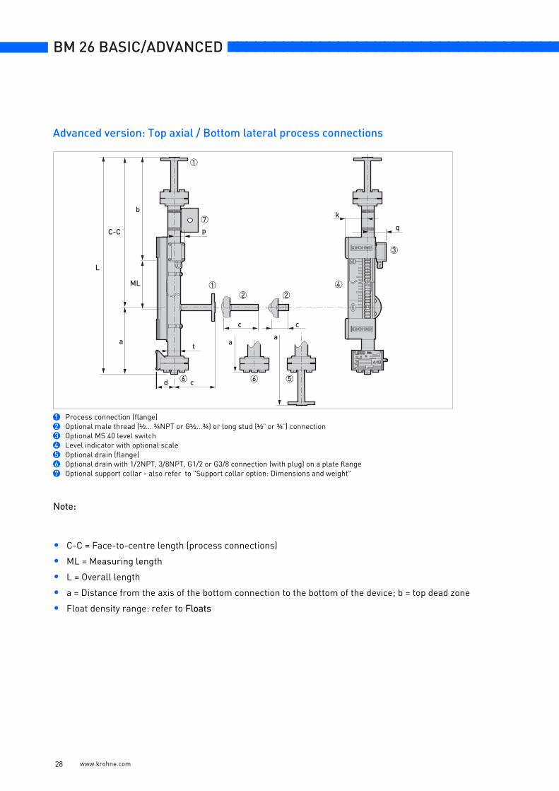
Basic version: Top axial / Bottom lateral process connections
1 Optional drain with 3/8 NPT or 1¼NPT connection (with plug - 1¼NPT connection is for removing the float)2 3/8 NPTF threaded connection3 Flange connection4 Optional long stud (½¨ or ¾¨) connection5 Optional male thread (½... ¾NPT or G½...¾) connection6 Optional MS 40 limit switch7 Level indicator with optional scale8 Optional support collar - also refer to "Support collar option: Dimensions and weight"
C-C
t
d c
a
c c
ML
p
q
L
b
a
1
2
1
67
8
543
k
www.krohne.com 20
nnnnnnnnnnnnnnnnnnnnnnnnnnnnnnnnnnnnn BM 26 BASIC/ADVANCED
Dimensions in mm
Dimensions in inches
Weight in kg and lbs
Dimensions [mm]
a b C-C ML c d k L p q t
Top axial / Bottom lateralprocess connections
310 1 2 428…6000
(C-C) -140
135.23
55.5 74 (C-C)+310 4
38 38 Ø42.4
1 optional drain with 1¼¨ plug: 323 mm2 depends on the options selected. Contact your local sales office for more data.3 long stud option: 130.2 mm. Male thread connection option: 58.2 mm.4 1¼¨ plug option: (C-C) +327 mm
Dimensions [inches]
a b C-C ML c d k L p q t
Top axial / Bottom lateralprocess connections
12.2 1 2 16.9…236
(C-C) -5.5
5.3 3 2.2 2.9 (C-C)+12.2 4
38 63 Ø1.7
1 optional drain with 1¼¨ plug: 12.7¨2 depends on the options selected. Contact your local sales office for more data.3 long stud option: 5.1¨. Male thread connection option: 2.3¨.4 1¼¨ plug option: (C-C) +12.9¨
WeightWeight for every
additional 100 mmWeight for every
additional 4 inches
[kg] [lbs] [kg] [lbs]
Min. 3/8 NPTF/DN15 PN40 flange 6.7 1 14.8 2 0.3 0.7
Max. 3/8 NPTF/1½¨ 300LB flange 8.6 1 19.0 2 0.3 0.7
Limit switch 0.085 0.2
1 when L=500 mm2 when L=20 inches
www.krohne.com 21
BM 26 BASIC/ADVANCED nnnnnnnnnnnnnnnnnnnnnnnnnnnnnnnnnnnnn
Note:
• C-C = Centre-to-centre length (process connections)
• ML = Measuring length
• L = Overall length
• a = Distance from the axis of the bottom connection to the bottom of the device; b = Distance from the axis of the top connection to the top of the device
• Float density range: refer to Floats
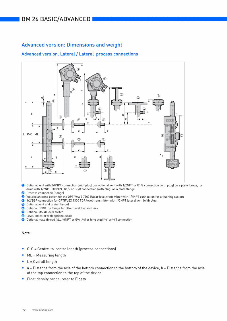
Advanced version: Lateral / Lateral process connections
1 Optional vent with 3/8NPT connection (with plug) , or optional vent with 1/2NPT or G1/2 connection (with plug) on a plate flange, or drain with 1/2NPT, 3/8NPT, G1/2 or G3/8 connection (with plug) on a plate flange
2 Process connection (flange)3 Welded antenna option for the OPTIWAVE 7300 Radar level transmitter with 1/4NPT connection for a flushing system4 1/2¨BSP connection for OPTIFLEX 1300 TDR level transmitter with 1/2NPT lateral vent (with plug)5 Optional vent and drain (flange)6 Optional DN40 top flange for other level transmitters7 Optional MS 40 level switch8 Level indicator with optional scale9 Optional male thread (½... ¾NPT or G½...¾) or long stud (½¨ or ¾¨) connection
c c
99
c c
9 9
c
a a
b
C-C ML
t
1
2
78
4
4
6
6
1d
b
bee
g
a
b
5
2
51
3
3
b
L
1
s
p
q
k
r r
Advanced version: Dimensions and weight
www.krohne.com 22
nnnnnnnnnnnnnnnnnnnnnnnnnnnnnnnnnnnnn BM 26 BASIC/ADVANCED
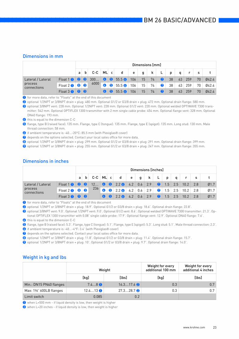
Dimensions in mm
Dimensions in inches
Weight in kg and lbs
Dimensions [mm]
a b C-C ML c d e g k L p q r s t
Lateral / Lateralprocess connections
Float 1 1 2 3 300…6000
4 5 55.5 6 106 15 74 7 38 63 259 70 Ø42.4
Float 2 1 8 3 4 5 55.5 6 106 15 74 7 38 63 259 70 Ø42.4
Float 3 1 9 3 4 5 55.5 6 106 15 74 7 38 63 259 70 Ø42.4
1 for more data, refer to "Floats" at the end of this document2 optional 1/2NPT or 3/8NPT drain + plug: 480 mm. Optional G1/2 or G3/8 drain + plug: 472 mm. Optional drain flange: 580 mm.3 optional 3/8NPT vent: 228 mm. Optional 1/2NPT vent: 228 mm. Optional G1/2 vent: 220 mm. Optional welded OPTIWAVE 7300 trans-
mitter: 542 mm. Optional OPTIFLEX 1300 transmitter with 2 mm single cable probe: 454 mm. Optional flange vent: 328 mm. Optional DN40 flange: 193 mm.
4 this is equal to the dimension C-C5 flange, type B (raised face): 135 mm. Flange, type C (tongue): 135 mm. Flange, type E (spigot): 135 mm. Long stud: 130 mm. Male
thread connection: 58 mm.6 if ambient temperature is -40...-20°C: 85.5 mm (with Plexiglas® cover)7 depends on the options selected. Contact your local sales office for more data.8 optional 1/2NPT or 3/8NPT drain + plug: 299 mm. Optional G1/2 or G3/8 drain + plug: 291 mm. Optional drain flange: 399 mm.9 optional 1/2NPT or 3/8NPT drain + plug: 255 mm. Optional G1/2 or G3/8 drain + plug: 247 mm. Optional drain flange: 355 mm.
Dimensions [inches]
a b C-C ML c d e g k L p q r s t
Lateral / Lateralprocess connections
Float 1 1 2 3 12…236
4 5 2.2 6 4.2 0.6 2.9 7 1.5 2.5 10.2 2.8 Ø1.7
Float 2 1 8 3 4 5 2.2 6 4.2 0.6 2.9 7 1.5 2.5 10.2 2.8 Ø1.7
Float 3 1 9 3 4 5 2.2 6 4.2 0.6 2.9 7 1.5 2.5 10.2 2.8 Ø1.7
1 for more data, refer to "Floats" at the end of this document2 optional 1/2NPT or 3/8NPT drain + plug: 18.9¨. Optional G1/2 or G3/8 drain + plug: 18.6¨. Optional drain flange: 22.8¨.3 optional 3/8NPT vent: 9.0¨. Optional 1/2NPT vent: 9.0¨. Optional G1/2 vent: 8.6¨. Optional welded OPTIWAVE 7300 transmitter: 21.3¨. Op-
tional OPTIFLEX 1300 transmitter with 0.08¨ single cable probe: 17.9¨. Optional flange vent: 12.9¨. Optional DN40 flange: 7.6¨.4 this is equal to the dimension C-C5 flange, type B (raised face): 5.3¨. Flange, type C (tongue): 5.1¨. Flange, type E (spigot): 5.3¨. Long stud: 5.1¨. Male thread connection: 2.3¨.6 if ambient temperature is -40...-4°F: 3.4¨ (with Plexiglas® cover)7 depends on the options selected. Contact your local sales office for more data.8 optional 1/2NPT or 3/8NPT drain + plug: 11.8¨. Optional G1/2 or G3/8 drain + plug: 11.4¨. Optional drain flange: 15.7¨.9 optional 1/2NPT or 3/8NPT drain + plug: 10¨. Optional G1/2 or G3/8 drain + plug: 9.7¨. Optional drain flange: 14.0¨.
WeightWeight for every
additional 100 mmWeight for every
additional 4 inches
[kg] [lbs] [kg] [lbs]
Min.: DN15 PN40 flanges 7.4…8 1 16.3…17.6 2 0.3 0.7
Max: 1½¨ 600LB flanges 12.4…13 1 27.3…28.7 2 0.3 0.7
Limit switch 0.085 0.2
1 when L=500 mm - if liquid density is low, then weight is higher2 when L=20 inches - if liquid density is low, then weight is higher
www.krohne.com 23
BM 26 BASIC/ADVANCED nnnnnnnnnnnnnnnnnnnnnnnnnnnnnnnnnnnnn
Note:
• C-C = Face-to-face length (process connections)
• ML = Measuring length
• L = Overall length
• a = bottom dead zone; b = top dead zone
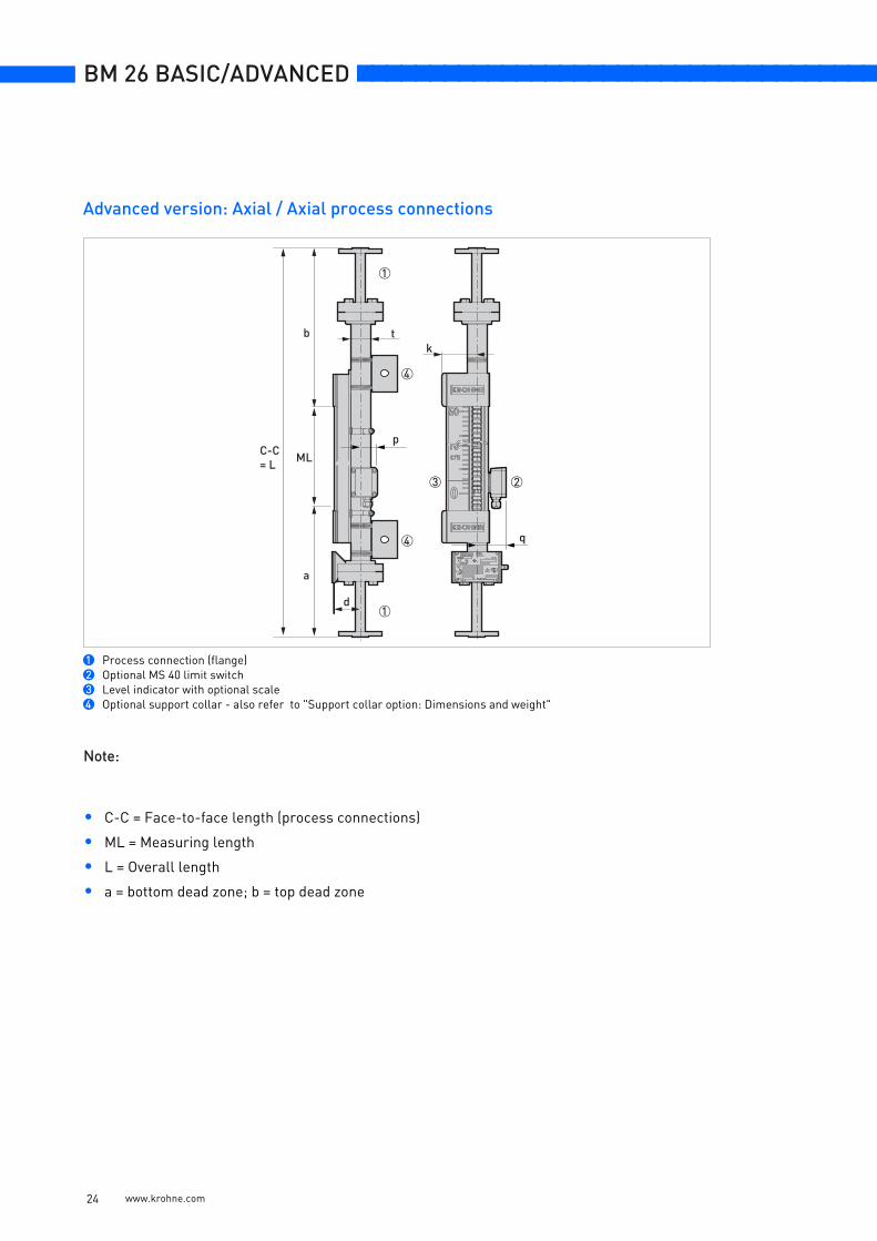
Advanced version: Axial / Axial process connections
1 Process connection (flange)2 Optional MS 40 limit switch3 Level indicator with optional scale4 Optional support collar - also refer to "Support collar option: Dimensions and weight"
1
t
d
q
p
a
b
C-C= L ML
23
1
4
4
k
www.krohne.com 24
nnnnnnnnnnnnnnnnnnnnnnnnnnnnnnnnnnnnn BM 26 BASIC/ADVANCED
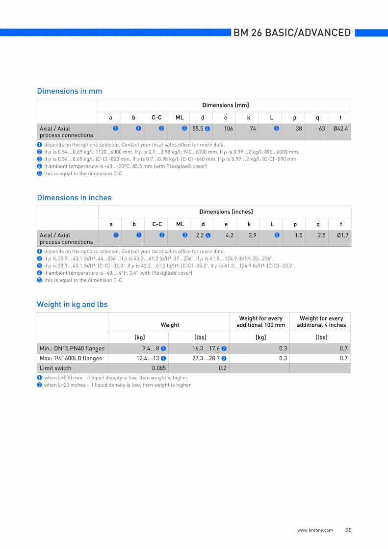
Dimensions in mm
Dimensions in inches
Weight in kg and lbs
Dimensions [mm]
a b C-C ML d e k L p q t
Axial / Axialprocess connections
1 1 2 3 55.5 4 106 74 5 38 63 Ø42.4
1 depends on the options selected. Contact your local sales office for more data.2 if ρ is 0.54…0.69 kg/l: 1120...6000 mm. If ρ is 0.7…0.98 kg/l: 940...6000 mm. If ρ is 0.99…2 kg/l: 890...6000 mm.3 if ρ is 0.54…0.69 kg/l: (C-C) -820 mm. If ρ is 0.7…0.98 kg/l: (C-C) -640 mm. If ρ is 0.99…2 kg/l: (C-C) -590 mm.4 if ambient temperature is -40...-20°C: 85.5 mm (with Plexiglas® cover)5 this is equal to the dimension C-C
Dimensions [inches]
a b C-C ML d e k L p q t
Axial / Axialprocess connections
1 1 2 3 2.2 4 4.2 2.9 5 1.5 2.5 Ø1.7
1 depends on the options selected. Contact your local sales office for more data.2 if ρ is 33.7…43.1 lb/ft³: 44...236¨. If ρ is 43.2…61.2 lb/ft³: 37...236¨. If ρ is 61.3…124.9 lb/ft³: 35...236¨.3 if ρ is 33.7…43.1 lb/ft³: (C-C) -32.3¨. If ρ is 43.2…61.2 lb/ft³: (C-C) -25.2¨. If ρ is 61.3…124.9 lb/ft³: (C-C) -23.2¨.4 if ambient temperature is -40...-4°F: 3.4¨ (with Plexiglas® cover)5 this is equal to the dimension C-C
WeightWeight for every
additional 100 mmWeight for every
additional 4 inches
[kg] [lbs] [kg] [lbs]
Min.: DN15 PN40 flanges 7.4…8 1 16.3…17.6 2 0.3 0.7
Max: 1½¨ 600LB flanges 12.4…13 1 27.3…28.7 2 0.3 0.7
Limit switch 0.085 0.2
1 when L=500 mm - if liquid density is low, then weight is higher2 when L=20 inches - if liquid density is low, then weight is higher
www.krohne.com 25
BM 26 BASIC/ADVANCED nnnnnnnnnnnnnnnnnnnnnnnnnnnnnnnnnnnnn
Note:
• C-C = Centre-to-face length (process connections)
• ML = Measuring length
• L = Overall length
• a = bottom dead zone; b = Distance from the axis of top connection to the top of the device
Advanced version: Top lateral / Bottom axial process connections
1 Optional vent with 3/8NPT connection (with plug) or optional vent with ½NPT or G½ connection (with plug) on a plate flange2 Process connection (flange)3 Welded antenna option for the OPTIWAVE 7300 Radar level transmitter with ¼NPT connection for a flushing system4 ½¨BSP connection for OPTIFLEX 1300 TDR level transmitter with ½NPT lateral vent (with plug)5 Optional vent (flange)6 Optional DN40 top flange for other level transmitters with ½NPT lateral vent (with plug)7 Optional MS 40 level switch8 Level indicator with optional scale9 Optional male thread (½... ¾NPT or G½...¾) or long stud (½¨ or ¾¨) connection10 Optional support collar - also refer to "Support collar option: Dimensions and weight"
10
c c
99
11
2
78
tb
C-C
b
b
MLp
q
cd
g
2
3
3
4
4
6
6
5
e
b
e
b b
L
a
k
r r
s
www.krohne.com 26
nnnnnnnnnnnnnnnnnnnnnnnnnnnnnnnnnnnnn BM 26 BASIC/ADVANCED
Dimensions in mm
Dimensions in inches
Weight in kg and lbs
Dimensions [mm]
a b C-C ML c d e g k L p q r s t
Top lateral / Bottom axialprocess connections
1 2 3 4 5 55.56
106 15 74 1 38 63 259 70 Ø42.4
1 depends on the options selected. Contact your local sales office for more data.2 optional 3/8NPT vent: 228mm. Optional 1/2NPT vent: 228 mm. Optional G1/2 vent: 220 mm. Optional welded OPTIWAVE 7300 transmit-
ter: 542 mm. Optional OPTIFLEX 1300 transmitter with 2 mm single cable probe: 454 mm. Optional flange vent: 328 mm. Optional DN40 flange: 193 mm.
3 if ρ is 0.54…0.69 kg/l: 880...6000 mm. If ρ is 0.7…0.98 kg/l: 700...6000 mm. If ρ is 0.99…2 kg/l: 660...6000 mm.4 if ρ is 0.54…0.69 kg/l: (C-C) -580 mm. If ρ is 0.7…0.98 kg/l: (C-C) -400 mm. If ρ is 0.99…2 kg/l: (C-C) -360 mm.5 flange, type B (raised face): 135.2 mm. Flange, type C (tongue): 134.7 mm. Flange, type E (spigot): 135.2 mm. Long stud: 130.2 mm.
Male thread connection: 58.2 mm.6 if ambient temperature is -40...-20°C: 85.5 mm (with Plexiglas® cover)
Dimensions [inches]
a b C-C ML c d e g k L p q r s t
Top lateral / Bottom axialprocess connections
1 2 3 4 5 2.26
4.2 0.6 2.9 1 1.5 2.5 10.2 2.8 Ø1.7
1 depends on the options selected. Contact your local sales office for more data.2 optional 3/8NPT vent: 9.0¨. Optional 1/2NPT vent: 9.0¨. Optional G1/2 vent: 8.6¨. Optional welded OPTIWAVE 7300 transmitter: 21.3¨. Op-
tional OPTIFLEX 1300 transmitter with 0.08¨ single cable probe: 17.9¨. Optional flange vent: 12.9¨. Optional DN40 flange: 7.6¨.3 if ρ is 33.7…43.1 lb/ft³: 35...236¨. If ρ is 43.2…61.2 lb/ft³: 27.6...236¨. If ρ is 61.3…124.9 lb/ft³: 26...236¨.4 if ρ is 33.7…43.1 lb/ft³: (C-C) -22.8¨. If ρ is 43.2…61.2 lb/ft³: (C-C) -15.7¨. If ρ is 61.3…124.9 lb/ft³: (C-C) -14.2¨.5 flange, type B (raised face): 5.3¨. Flange, type C (tongue): 5.1¨. Flange, type E (spigot): 5.3¨. Long stud: 5.1¨. Male thread connection: 2.3¨.6 if ambient temperature is -40...-4°F: 3.4¨ (with Plexiglas® cover)
WeightWeight for every
additional 100 mmWeight for every
additional 4 inches
[kg] [lbs] [kg] [lbs]
Min.: DN15 PN40 flanges 6.7…7.3 1 14.8…16.1 2 0.3 0.7
Max: 1½¨ 600LB flanges 9.2…9.8 1 20.3…21.6 2 0.3 0.7
Limit switch 0.085 0.2
1 when L=500 mm - if liquid density is low, then weight is higher2 when L=20 inches - if liquid density is low, then weight is higher
www.krohne.com 27
BM 26 BASIC/ADVANCED nnnnnnnnnnnnnnnnnnnnnnnnnnnnnnnnnnnnn
Note:
• C-C = Face-to-centre length (process connections)
• ML = Measuring length
• L = Overall length
• a = Distance from the axis of the bottom connection to the bottom of the device; b = top dead zone
• Float density range: refer to Floats
Advanced version: Top axial / Bottom lateral process connections
1 Process connection (flange)2 Optional male thread (½... ¾NPT or G½...¾) or long stud (½¨ or ¾¨) connection3 Optional MS 40 level switch4 Level indicator with optional scale5 Optional drain (flange)6 Optional drain with 1/2NPT, 3/8NPT, G1/2 or G3/8 connection (with plug) on a plate flange7 Optional support collar - also refer to "Support collar option: Dimensions and weight"
c c
22
c
ta
C-C
66
1
d
p q
a
ML
5
3
4
a
1
7
L
bk
www.krohne.com 28
nnnnnnnnnnnnnnnnnnnnnnnnnnnnnnnnnnnnn BM 26 BASIC/ADVANCED
Dimensions in mm
Dimensions in inches
Weight in kg and lbs
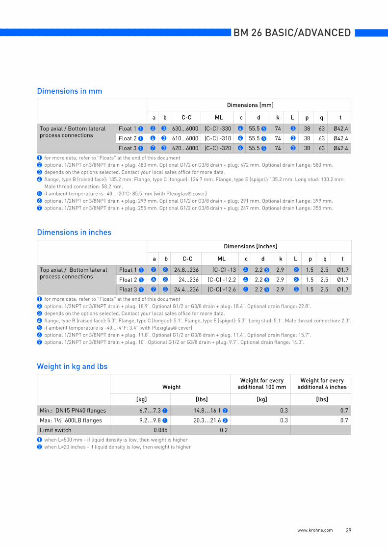
Dimensions [mm]
a b C-C ML c d k L p q t
Top axial / Bottom lateralprocess connections
Float 1 1 2 3 630...6000 (C-C) -330 4 55.5 5 74 3 38 63 Ø42.4
Float 2 1 6 3 610...6000 (C-C) -310 4 55.5 5 74 3 38 63 Ø42.4
Float 3 1 7 3 620...6000 (C-C) -320 4 55.5 5 74 3 38 63 Ø42.4
1 for more data, refer to "Floats" at the end of this document2 optional 1/2NPT or 3/8NPT drain + plug: 480 mm. Optional G1/2 or G3/8 drain + plug: 472 mm. Optional drain flange: 580 mm.3 depends on the options selected. Contact your local sales office for more data.4 flange, type B (raised face): 135.2 mm. Flange, type C (tongue): 134.7 mm. Flange, type E (spigot): 135.2 mm. Long stud: 130.2 mm.
Male thread connection: 58.2 mm.5 if ambient temperature is -40...-20°C: 85.5 mm (with Plexiglas® cover)6 optional 1/2NPT or 3/8NPT drain + plug: 299 mm. Optional G1/2 or G3/8 drain + plug: 291 mm. Optional drain flange: 399 mm.7 optional 1/2NPT or 3/8NPT drain + plug: 255 mm. Optional G1/2 or G3/8 drain + plug: 247 mm. Optional drain flange: 355 mm.
Dimensions [inches]
a b C-C ML c d k L p q t
Top axial / Bottom lateralprocess connections
Float 1 1 2 3 24.8...236 (C-C) -13 4 2.2 5 2.9 3 1.5 2.5 Ø1.7
Float 2 1 6 3 24...236 (C-C) -12.2 4 2.2 5 2.9 3 1.5 2.5 Ø1.7
Float 3 1 7 3 24.4...236 (C-C) -12.6 4 2.2 5 2.9 3 1.5 2.5 Ø1.7
1 for more data, refer to "Floats" at the end of this document2 optional 1/2NPT or 3/8NPT drain + plug: 18.9¨. Optional G1/2 or G3/8 drain + plug: 18.6¨. Optional drain flange: 22.8¨.3 depends on the options selected. Contact your local sales office for more data.4 flange, type B (raised face): 5.3¨. Flange, type C (tongue): 5.1¨. Flange, type E (spigot): 5.3¨. Long stud: 5.1¨. Male thread connection: 2.3¨.5 if ambient temperature is -40...-4°F: 3.4¨ (with Plexiglas® cover)6 optional 1/2NPT or 3/8NPT drain + plug: 11.8¨. Optional G1/2 or G3/8 drain + plug: 11.4¨. Optional drain flange: 15.7¨.7 optional 1/2NPT or 3/8NPT drain + plug: 10¨. Optional G1/2 or G3/8 drain + plug: 9.7¨. Optional drain flange: 14.0¨.
WeightWeight for every
additional 100 mmWeight for every
additional 4 inches
[kg] [lbs] [kg] [lbs]
Min.: DN15 PN40 flanges 6.7…7.3 1 14.8…16.1 2 0.3 0.7
Max: 1½¨ 600LB flanges 9.2…9.8 1 20.3…21.6 2 0.3 0.7
Limit switch 0.085 0.2
1 when L=500 mm - if liquid density is low, then weight is higher2 when L=20 inches - if liquid density is low, then weight is higher
www.krohne.com 29
BM 26 BASIC/ADVANCED nnnnnnnnnnnnnnnnnnnnnnnnnnnnnnnnnnnnn
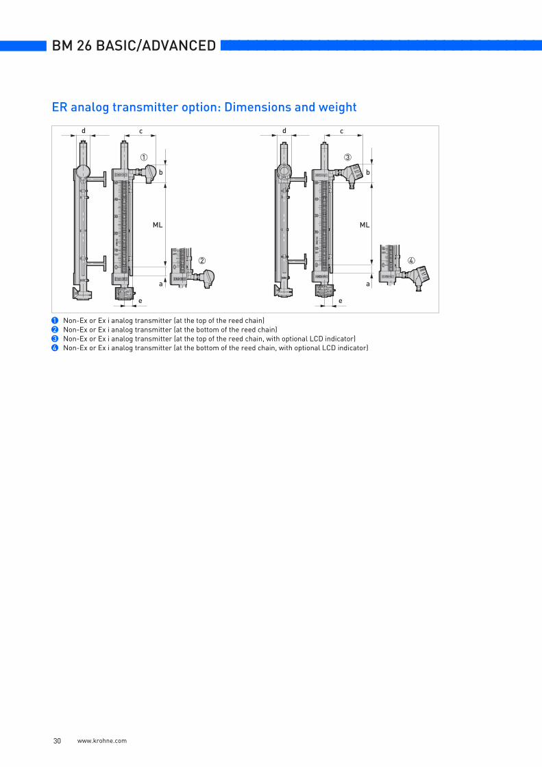
1 Non-Ex or Ex i analog transmitter (at the top of the reed chain)2 Non-Ex or Ex i analog transmitter (at the bottom of the reed chain)3 Non-Ex or Ex i analog transmitter (at the top of the reed chain, with optional LCD indicator)4 Non-Ex or Ex i analog transmitter (at the bottom of the reed chain, with optional LCD indicator)
e
ML ML
a
e
b
a
b
cd cd
1
2
3
4
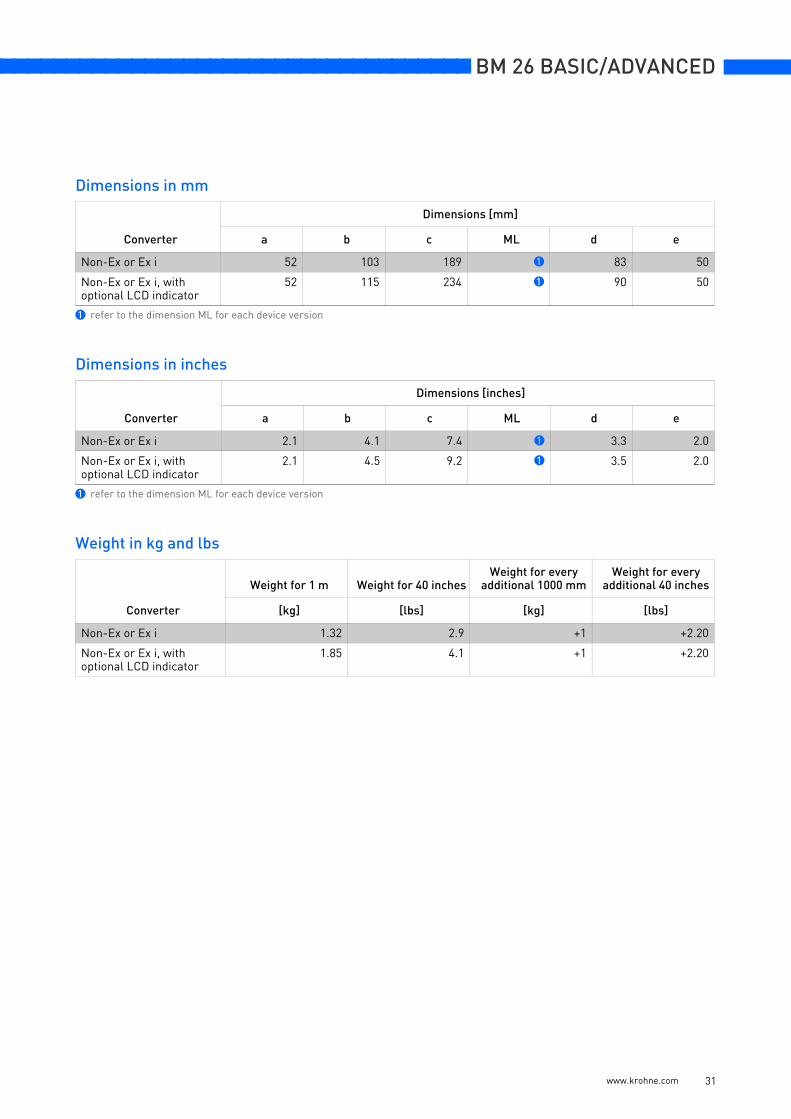
ER analog transmitter option: Dimensions and weight
www.krohne.com 30
nnnnnnnnnnnnnnnnnnnnnnnnnnnnnnnnnnnnn BM 26 BASIC/ADVANCED
Dimensions in mm
Dimensions in inches
Weight in kg and lbs
Converter
Dimensions [mm]
a b c ML d e
Non-Ex or Ex i 52 103 189 1 83 50
Non-Ex or Ex i, with optional LCD indicator
52 115 234 1 90 50
1 refer to the dimension ML for each device version
Converter
Dimensions [inches]
a b c ML d e
Non-Ex or Ex i 2.1 4.1 7.4 1 3.3 2.0
Non-Ex or Ex i, with optional LCD indicator
2.1 4.5 9.2 1 3.5 2.0
1 refer to the dimension ML for each device version
Converter
Weight for 1 m Weight for 40 inchesWeight for every
additional 1000 mmWeight for every
additional 40 inches
[kg] [lbs] [kg] [lbs]
Non-Ex or Ex i 1.32 2.9 +1 +2.20
Non-Ex or Ex i, with optional LCD indicator
1.85 4.1 +1 +2.20
www.krohne.com 31
BM 26 BASIC/ADVANCED nnnnnnnnnnnnnnnnnnnnnnnnnnnnnnnnnnnnn
www.krohne.com 32
Dimensions and weight in mm and kg
Dimensions and weight in inches and lbs
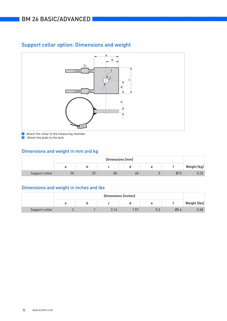
1 Attach the collar to the measuring chamber2 Attach the plate to the tank
Dimensions [mm]
Weight [kg]a b c d e f
Support collar 50 25 80 40 5 Ø15 0.22
Dimensions [inches]
Weight [lbs]a b c d e f
Support collar 2 1 3.14 1.57 0.2 Ø0.6 0.48
a
b
c
d
e
f
1
2
Support collar option: Dimensions and weight
nnnnnnnnnnnnnnnnnnnnnnnnnnnnnnnnnnnnn BM 26 BASIC/ADVANCED
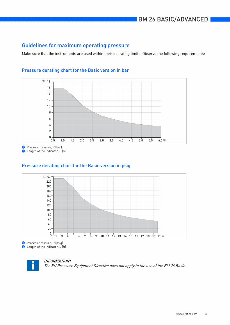
Make sure that the instruments are used within their operating limits. Observe the following requirements:
Pressure derating chart for the Basic version in bar
1 Process pressure, P [bar]2 Length of the indicator, L [m]
Pressure derating chart for the Basic version in psig
1 Process pressure, P [psig]2 Length of the indicator, L [ft]
INFORMATION!The EU Pressure Equipment Directive does not apply to the use of the BM 26 Basic.
�
�
��� ��� ��� ��� ��� ��� ��� ��� ��� ��� ��� ���
�
�
��
��
��
�
�
�
�
���� � � � � � �� �� �� �� �� �� � �� � �� ���
��
��
�
�
���
���
���
��
�����
���
���
Guidelines for maximum operating pressure
www.krohne.com 33
BM 26 BASIC/ADVANCED nnnnnnnnnnnnnnnnnnnnnnnnnnnnnnnnnnnnn
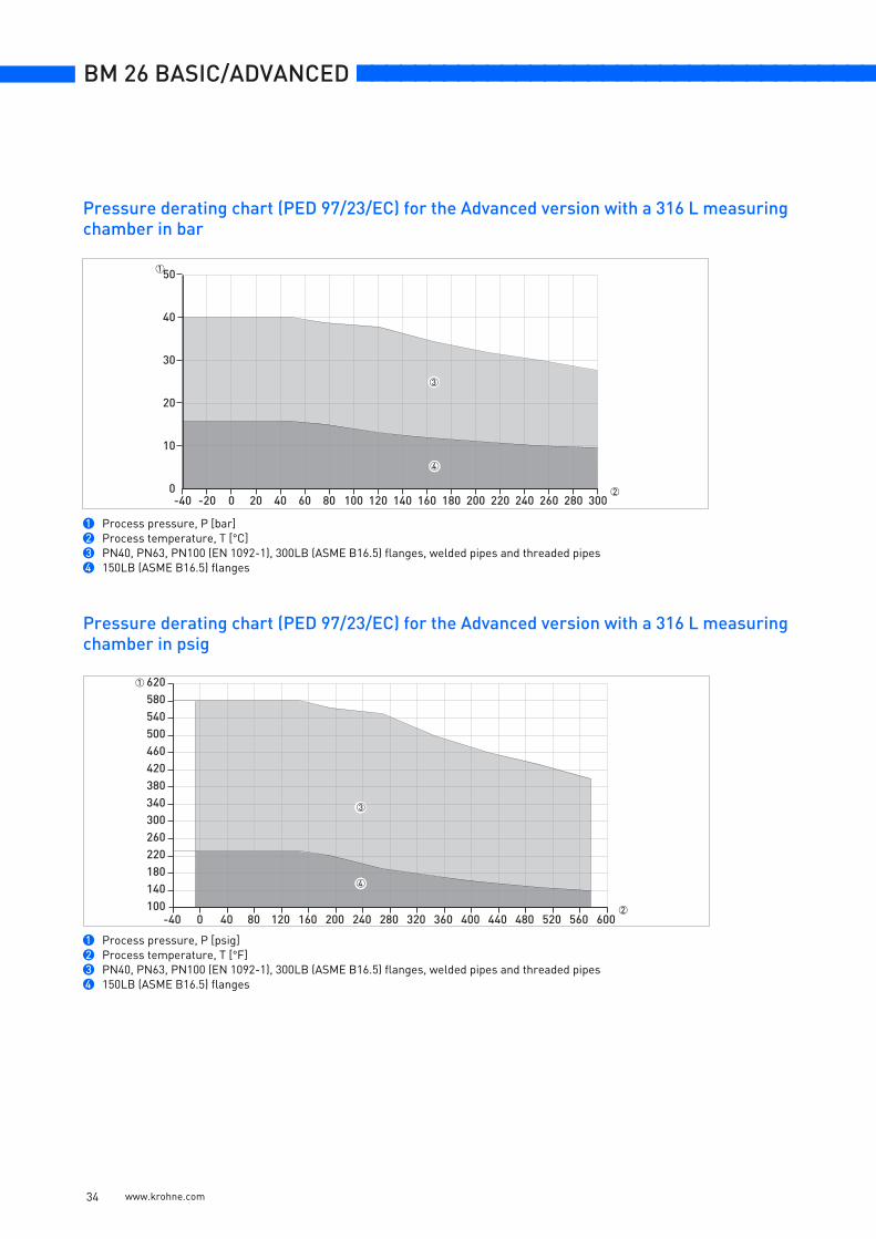
Pressure derating chart (PED 97/23/EC) for the Advanced version with a 316 L measuring chamber in bar
1 Process pressure, P [bar]2 Process temperature, T [°C]3 PN40, PN63, PN100 (EN 1092-1), 300LB (ASME B16.5) flanges, welded pipes and threaded pipes4 150LB (ASME B16.5) flanges
Pressure derating chart (PED 97/23/EC) for the Advanced version with a 316 L measuring chamber in psig
1 Process pressure, P [psig]2 Process temperature, T [°F]3 PN40, PN63, PN100 (EN 1092-1), 300LB (ASME B16.5) flanges, welded pipes and threaded pipes4 150LB (ASME B16.5) flanges
�� �� � �� �� � � ��� ��� ��� �� �� ��� ��� ��� �� �� ����
��
��
��
��
���
�
�
�
�� � �� � ��� �� ��� ��� �� ��� �� ��� ��� �� ��� �� ���������������������������������������
�
�
�
www.krohne.com 34
nnnnnnnnnnnnnnnnnnnnnnnnnnnnnnnnnnnnn BM 26 BASIC/ADVANCED
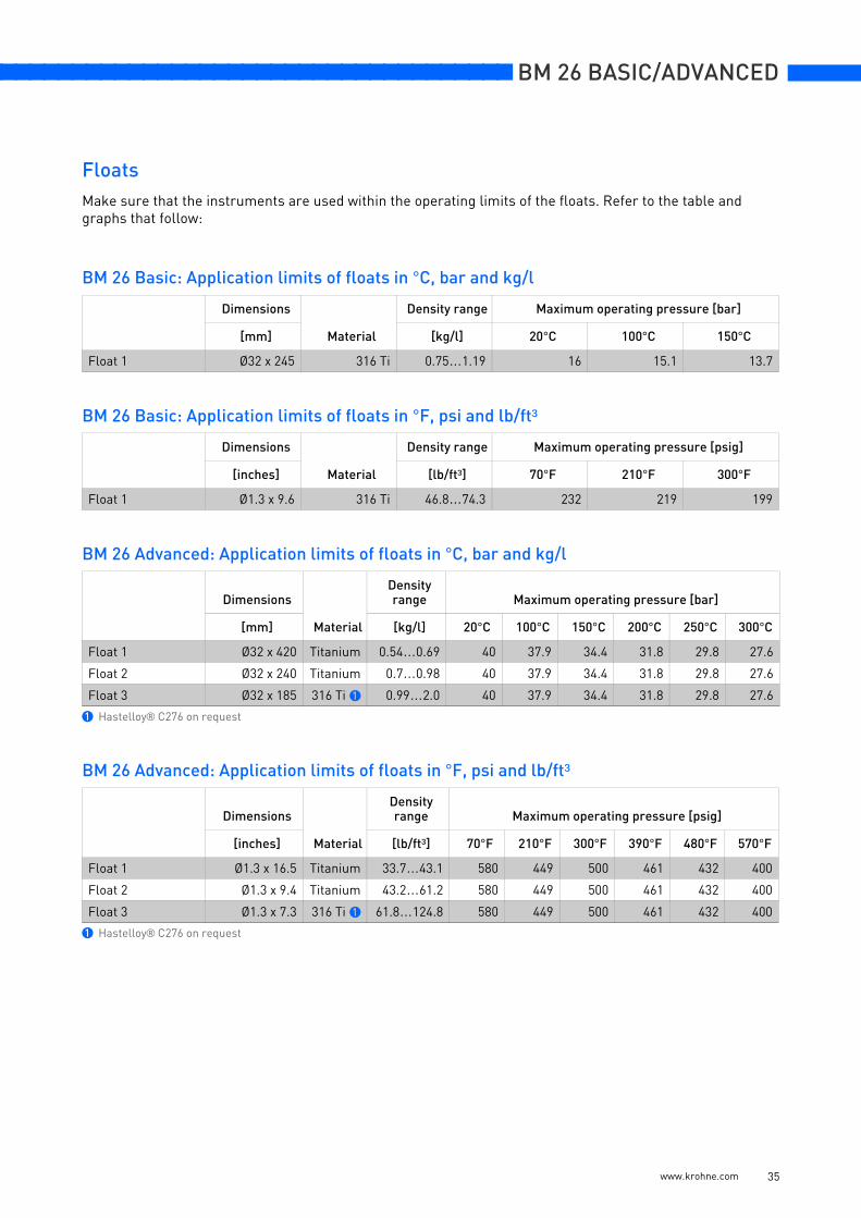
Make sure that the instruments are used within the operating limits of the floats. Refer to the table and graphs that follow:
BM 26 Basic: Application limits of floats in °C, bar and kg/l
BM 26 Basic: Application limits of floats in °F, psi and lb/ft³
BM 26 Advanced: Application limits of floats in °C, bar and kg/l
BM 26 Advanced: Application limits of floats in °F, psi and lb/ft³
Dimensions
Material
Density range Maximum operating pressure [bar]
[mm] [kg/l] 20°C 100°C 150°C
Float 1 Ø32 x 245 316 Ti 0.75…1.19 16 15.1 13.7
Dimensions
Material
Density range Maximum operating pressure [psig]
[inches] [lb/ft³] 70°F 210°F 300°F
Float 1 Ø1.3 x 9.6 316 Ti 46.8…74.3 232 219 199
Dimensions
Material
Density range Maximum operating pressure [bar]
[mm] [kg/l] 20°C 100°C 150°C 200°C 250°C 300°C
Float 1 Ø32 x 420 Titanium 0.54…0.69 40 37.9 34.4 31.8 29.8 27.6
Float 2 Ø32 x 240 Titanium 0.7…0.98 40 37.9 34.4 31.8 29.8 27.6
Float 3 Ø32 x 185 316 Ti 1 0.99…2.0 40 37.9 34.4 31.8 29.8 27.6
1 Hastelloy® C276 on request
Dimensions
Material
Density range Maximum operating pressure [psig]
[inches] [lb/ft³] 70°F 210°F 300°F 390°F 480°F 570°F
Float 1 Ø1.3 x 16.5 Titanium 33.7…43.1 580 449 500 461 432 400
Float 2 Ø1.3 x 9.4 Titanium 43.2…61.2 580 449 500 461 432 400
Float 3 Ø1.3 x 7.3 316 Ti 1 61.8…124.8 580 449 500 461 432 400
1 Hastelloy® C276 on request
Floats
www.krohne.com 35
BM 26 BASIC/ADVANCED nnnnnnnnnnnnnnnnnnnnnnnnnnnnnnnnnnnnn
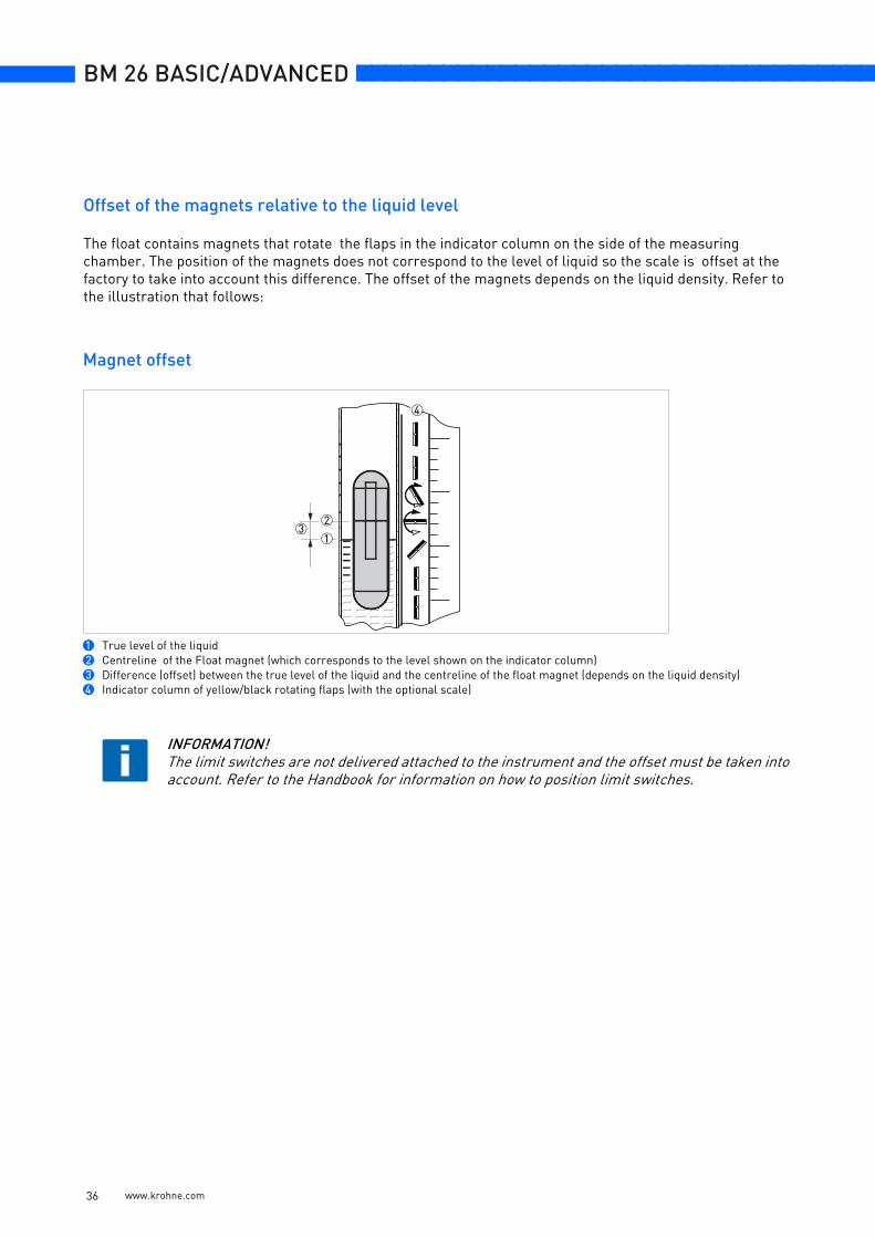
Offset of the magnets relative to the liquid level
The float contains magnets that rotate the flaps in the indicator column on the side of the measuring chamber. The position of the magnets does not correspond to the level of liquid so the scale is offset at the factory to take into account this difference. The offset of the magnets depends on the liquid density. Refer to the illustration that follows:
Magnet offset
1 True level of the liquid2 Centreline of the Float magnet (which corresponds to the level shown on the indicator column)3 Difference (offset) between the true level of the liquid and the centreline of the float magnet (depends on the liquid density)4 Indicator column of yellow/black rotating flaps (with the optional scale)
INFORMATION!The limit switches are not delivered attached to the instrument and the offset must be taken into account. Refer to the Handbook for information on how to position limit switches.
1
23
4
www.krohne.com 36

nnnnnnnnnnnnnnnnnnnnnnnnnnnnnnnnnnnnn BM 26 BASIC/ADVANCED
www.krohne.com 37
$$$
BM 26 BASIC/ADVANCED nnnnnnnnnnnnnnnnnnnnnnnnnnnnnnnnnnnnn
www.krohne.com 38
$$$
nnnnnnnnnnnnnnnnnnnnnnnnnnnnnnnnnnnnn BM 26 BASIC/ADVANCED
www.krohne.com 39
$$$
BM 26 BASIC/ADVANCED nnnnnnnnnnnnnnnnnnnnnnnnnnnnnnnnnnnnn
www.krohne.com
Addresses:
Germany
Northern sales office
KROHNE Messtechnik GmbH & Co. KG Bremer Str. 133D-21073 HamburgPhone:+49 (0)40 767 3340 Fax:+49 (0)40 767 33412 [email protected] ZIP code: 10000 - 29999, 49000 - 49999
Western and middle sales office
KROHNE Messtechnik GmbH & Co. KGLudwig-Krohne-StraßeD-47058 DuisburgPhone:+49 (0)203 301 4416 Fax:+49 (0)203 301 10416 [email protected] ZIP code: 30000 - 34999, 37000 - 48000, 50000 - 53999, 57000 - 59999, 98000 - 99999
Southern sales office
KROHNE Messtechnik GmbH & Co. KG Landsberger Str. 392 D-81241 Munich Phone:+49 (0)89 121 5620 Fax:+49 (0)89 129 6190 [email protected] code: 0 - 9999, 80000 - 89999, 90000 - 97999
Southwestern sales office
KROHNE Messtechnik GmbH & Co. KG Rüdesheimer Str. 40 D-65239 Hochheim/Main Phone: +49(0)6146) 827 30 Fax:+49 (0)6146 827 312 [email protected] ZIP code: 35000 - 36999, 54000 - 56999, 60000 - 79999
Instrumentation and control equipment catalog
TABLAR Messtechnik GmbH Ludwig-Krohne-Str. 5D-47058 Duisburg Phone:+49 (0)2 03 305 880 Fax:+49 (0)2 03 305 8888 [email protected]; www.tablar.de
KROHNE sales companies
International
Australia KROHNE Australia Pty LtdQuantum Business Park 10/287Victoria Rd Rydalmere NSW 2116 Phone: +61 2 8846 1700 Fax: +61 2 8846 1755 [email protected]
AustriaKROHNE Gesellschaft m.b.H.Modecenterstraße 14A-1030 ViennaPhone:+43 (0)1/203 45 32Fax:+43 (0)1/203 45 32 [email protected]
Belgium KROHNE Belgium N.V.Brusselstraat 320 B-1702 Groot Bijgaarden Phone:+32 (0)2 4 66 00 10 Fax:+32 (0)2 4 66 08 00 [email protected]
Brazil KROHNE Conaut Controles Automaticos Ltda. Estrada Das Águas Espraiadas, 230 C.P. 56 06835 - 080 EMBU - SP Phone:+55 (0)11-4785-2700 Fax:+55 (0)11 4785-2768 [email protected]
ChinaKROHNE Measurement Instruments (Shanghai) Co. Ltd., (KMIC)9th Floor, Puyuan Science Park, Building A396 Guilin RoadShanghai 200233Tel.: +86 (021) 6470 5656Fax: +86 (021) 6451 [email protected]
Czech RepublicKrohne CZ, spol. s r.o.Sobìsická 15663800 BrnoPhone: +420 (0)545.242 627Fax: +420 (0)545 220 [email protected]
FranceKROHNE S.A.S.Les Ors BP 98F-26103 ROMANS CedexPhone:+33 (0)4 75 05 44 00Fax:+33 (0)4 75 05 00 [email protected]
Great BritainKROHNE Ltd.Rutherford Drive Park Farm Industrial Estate WellingboroughNorthants NN8 6AEPhone:+44 (0)19 33 408 500Fax:+44 (0)19 33 408 [email protected]
CISKanex KROHNE Engineering AGBusiness Centre "POLLARS", office 164Derbenevskaya nab., 11-B113114 Moscow/RussiaTel. / Fax: +7 (0)495 913-68-41Tel. / Fax: +7 (0)495 913-68-42Tel. / Fax: +7 (0)495 913-68-43Tel. / Fax: +7 (0)495 [email protected]
IndiaKrohne Marshall Ltd. A-34/35, M.I.D.C. Industrial Area,H-BlockPimpri Poona 411018Phone:+91 (0)202 744 2020Fax:+91 (0)202 744 [email protected]
IranKROHNE Liaison OfficeNorth Sohrevardi Ave. 26,Sarmad St., Apt. #9Tehran 15539Phone: +9821 8874 5973Fax: +9821 8850 [email protected]
ItalyKROHNE Italia Srl. Via V. Monti 75I-20145 MilanPhone:+39 02 4300 661Fax:+39 02 4300 [email protected]
KoreaKROHNE KoreaRoom 508 Miwon Bldg 43Yoido-Dong Youngdeungpo-KuSeoul, KoreaPhone: 00-82-2-782-1900Fax: [email protected]
NetherlandsKROHNE Nederland B.V.Kerkeplaat 14NL-3313 LC DordrechtPhone:+31 (0)78 630 6200Fax:+31 (0)78 630 6405Service Direct: +31 (0)78 630 [email protected]
NorwayKROHNE Norway A.S. Ekholtveien 114NO-1521 MossPhone:+47 (0)69 264 860Fax:+47 (0)69 267 [email protected]
PolandKROHNE Polska Sp.z.o.o.ul. Stary Rynek Oliwski 8a80-324 GdanskPhone: +48 (0)58 520 9211Fax.:+48 (0)58 520 [email protected]
SwitzerlandKROHNE AGUferstr. 90CH-4019 BaselPhone:+41 (0)61 638 30 30Fax:+41 (0)61 638 30 [email protected]
SingaporeTokyo Keiso - KROHNE (Singapore) Pte. Ltd.14, International Business Park, Jurong EastChiyoda Building, #01-01/02Singapore 609922Phone: (65) 6567 4548Fax : (65) 6567 [email protected]
Republic of South AfricaKROHNE Pty. Ltd.Bushbock CloseCorporate Park SouthMidrand, GautengP.O. Box 2069Midrand, 1685Tel.: +27 (0)11 314 1391Fax: +27 (0)11 314 [email protected]
SpainI.I. KROHNE IBERIA, S.r.l.Poligono Industrial NiloCalle Brasil, nº. 528806 Alcalá de Henares MadridPhone: +34 (0)91 883 2152Fax: +34 (0)91 883 4854 [email protected]
USAKROHNE, Inc.7 Dearborn RoadPeabody, MA 01960Phone: +1 (800) FLOWINGPhone: +1 (978) 535 6060 (in MA)[email protected]
Representatives
Algeria ArgentinaCameroonCanadaChileColumbiaCroatiaDenmarkEcuadorEgyptFinlandGabonGhanaGreeceHong KongHungaryIndonesiaIranIrelandIsraelIvory CoastJapanJordanKuwaitLibyaLithuaniaMalaysiaMauritiusMexicoMoroccoNew ZealandPeruPortugalRomaniaSaudi ArabiaSenegalSlovakiaSlovenia SwedenTaiwan ThailandTunisiaTurkeyVenezuelaYugoslavia
Other countries
KROHNE Messtechnik GmbH & Co. KGLudwig-Krohne-Str. 5D-47058 DuisburgPhone:+49 (0)203 301 0Fax:+49 (0)203 301 389 [email protected]
• Electromagnetic flowmeters • Level measuring instruments
• Variable area flowmeters • Temperature measuring instruments
• Mass flowmeters • Pressure measuring instruments
• Ultrasonic flowmeters • Analysis
• Vortex flowmeters • Oil and gas industry
• Flow controllers
KROHNE measuring technology - Product overview
© K
RO
HN
E06
/200
840
0030
5701
- T
D B
M26
Bas
ic/A
dv R
01 e
nSu
bjec
t to
chan
ge w
ithou
t not
ice
Top Related