


Languages
Pages
Legal

BLX Servo Drive PositionerUser Guide
Software Version: Issue 3.8 onwards
For engineering For engineeringassistance in Europe: assistance in the U.S.:Parker Hannifin plc Parker Hannifin CorporationDigiplan Division Digiplan Division21 Balena Close 5500 Business Park Drive, Suite DPoole, Dorset Rohnert Park, CA 94928England, BH17 7DX USATelephone: 01202-699000 Telephone: (800) 358-9070Fax: 01202-695750 Fax: (707) 584-8015
Part No: 1600.137.05 8th March 1995


IMPORTANT INFORMATION FOR USERS
Installation and Operation of Digiplan Equipment
It is important that Digiplan motion control equipment is installed and operated in such a way that all applicablesafety requirements are met. It is your responsibility as a user to ensure that you identify the relevant safetystandards and comply with them; failure to do so may result in damage to equipment and personal injury. Inparticular, you should study the contents of this user guide carefully before installing or operating the equipment.
Under no circumstances will the suppliers of the equipment be liable for any incidental, consequential or specialdamages of any kind whatsoever, including but not limited to lost profits arising from or in any way connectedwith the use of the equipment or this user guide.
! SAFETY WARNING
High-performance motion control equipment is capable of producing rapid movement and very high forces.Unexpected motion may occur especially during the development of controller programs. KEEP WELL CLEARof any machinery driven by stepper or servo motors. Never touch it while it is in operation.
This product is sold as a motion control component to be installed in a complete system using good engineeringpractice. Care must be taken to ensure that the product is installed and used in a safe manner according tolocal safety laws and regulations. In particular, the product must be enclosed such that no part is accessiblewhile power may be applied.
The information in this user guide, including any apparatus, methods, techniques, and concepts describedherein, are the proprietary property of Parker Digiplan or its licensors, and may not be copied, disclosed, or usedfor any purpose not expressly authorised by the owner thereof.
Since Digiplan constantly strives to improve all of its products, we reserve the right to modify equipment anduser guides without prior notice. No part of this user guide may be reproduced in any form without the priorconsent of Digiplan.
IBM PC AT XT are registered trademarks of International Business Machines CorporationWINDOWS is a registered trademark of Microsoft Corporation
© Digiplan Division of Parker Hannifin plc, 1995– All Rights Reserved –


User Guide Change Summary
The following is a summary of the primary changes to this user guidesince the last version was released. This user guide, version1600.137.05, supersedes version 1600.137.04.
When a user guide is updated, the new or changed text isdifferentiated with a change bar in the outside margin (this paragraphis an example). If an entire chapter is changed, the change bar islocated on the outside margin of the chapter title.
Changes introduced at revision 05 are:
Minor additions to Chapter 2.
Table 2-2 Switch Type Selection added.
Chapter 3, software scaling explanation changed.
Chapter 4, using Windows™ terminal emulator added.
Chapter 5, note added to SSB command and followingcommands HELP 13 added.


CONTENTS i
CONTENTS
List of Figures .......................................................................................................... ivList of Tables............................................................................................................iv
How To Use This Manual................................................................................ vAssumptions......................................................................................... vContents of This Manual ...................................................................... v
Chapter 1. INTRODUCTION....................................................................................1Chapter Objectives ......................................................................................... 1Product Description......................................................................................... 1Features.......................................................................................................... 1Front Panel Indicator.......................................................................................2Positioner Specification................................................................................... 3
Chapter 2. INTERFACING SIGNALS....................................................................... 5Chapter Objectives ......................................................................................... 5
Encoder Connector ..............................................................................6Main Connector ....................................................................................6
Signal Descriptions ......................................................................................... 7Encoder Input .......................................................................................7Clock .................................................................................................... 7Direction ............................................................................................... 7Inputs 1 to 7 ......................................................................................... 7E stop ...................................................................................................8+ and - Limits........................................................................................ 8+Jog, -Jog ............................................................................................ 8Home.................................................................................................... 8Output O1.............................................................................................9Output O2.............................................................................................9Output O3.............................................................................................9AN-OUT 1 ............................................................................................ 9AN-OUT2 .............................................................................................10Controller Connections......................................................................... 10Encoder Connector ..............................................................................10
Interfacing Circuit Arrangements .................................................................... 10Coupling Optically Isolated Outputs and Inputs ................................... 11Clock and Direction Inputs ................................................................... 12Limit and Home Inputs ......................................................................... 12ESTOP Input ........................................................................................ 14Trigger Inputs .......................................................................................15Jog Inputs.............................................................................................16Composite Fault Indicator .................................................................... 17In Position Indicator..............................................................................18
Chapter 3. BASIC MOTION CONTROL CONCEPTS.............................................. 19Chapter Objectives ......................................................................................... 19Motion Profiles ................................................................................................19
Preset Moves .......................................................................................19Incremental Preset Moves.................................................................... 19Absolute Preset Moves ........................................................................19Continuous Moves................................................................................ 20Registration Moves ..............................................................................20

ii BL/BR SERVO DRIVE POSITIONER OPTION USER GUIDE
Program Operation...............................................................................21Program Criteria ...................................................................................22Motion Profiles......................................................................................22Triangular Profile ..................................................................................22Trapezoidal Profile................................................................................23User Profiles .........................................................................................24Encoder Following................................................................................24Hardware Scaling .................................................................................25Software Scaling...................................................................................26Buffered Clock Mode............................................................................28Preset Following Index Mode ...............................................................29
Program Storage .............................................................................................29Write Protection ....................................................................................29
Motion Program Selection...............................................................................29Parameter Ranges ..........................................................................................30
Chapter 4. COMMUNICATING WITH THE POSITIONER........................................31Chapter Objectives..........................................................................................31
Command Interface ..............................................................................31Communication Parameters.................................................................31Installing the RS232C...........................................................................31
ZDDC ..............................................................................................................33Positioner Address Jumper Linking ......................................................33
Drive Configuration .........................................................................................34Using Windows™............................................................................................35
Chapter 5. PROGRAMMING ....................................................................................37Chapter Objectives..........................................................................................37Communicating with the Positioner .................................................................37Individual Commands......................................................................................38Immediate Commands ....................................................................................39Buffered Commands .......................................................................................39Buffer Capacity................................................................................................39Multiple Positioner Commands .......................................................................40Programming Modes .......................................................................................40
Normal Mode........................................................................................40Absolute Mode......................................................................................40Incremental Mode.................................................................................41Continuous Mode .................................................................................41Speed Change Mode............................................................................41
Command Types .............................................................................................42Start Move Commands.........................................................................42Loop Commands ..................................................................................43Stop Move Commands.........................................................................44Pause Commands................................................................................45Status Request Commands .................................................................45
Drive Energise/De-energise Function .............................................................46Homing Function .............................................................................................46Basic Programming Guide ..............................................................................48
Example 1 ............................................................................................49Example 2 ............................................................................................49
Sequences ......................................................................................................49Introduction...........................................................................................49
CONTENTS iii
Programming Sequences.....................................................................50Running Sequences............................................................................. 51Standalone Operation .......................................................................... 51
Interactive operation with a PC/PLC ...............................................................54Command Structure........................................................................................ 55
Basic Format ........................................................................................ 55Command Attributes .......................................................................................57
DETAILED COMMAND LIST ....................................................................................58Command summary........................................................................................ 141
Alphabetical Command Listing ..............................................................................146Chapter 6. SERVO TUNING ....................................................................................148
Tuning the Drive with a Positioner ..................................................................148Tuning Positioner with Drive in Torque Amp...................................................148
Tuning Parameters............................................................................... 148Terminal/ .............................................................................................. 149Computer .............................................................................................149Connecting the Loop............................................................................ 149Manual Tuning Procedure.................................................................... 150Setting Up Servo Parameters .............................................................. 151
Coarse Tuning ................................................................................................154Fine Tuning ..........................................................................................154
Notes on Tuning.............................................................................................. 156Servo Self-tuning ............................................................................................ 156
Index .......................................................................................................................... 158
iv BL/BR SERVO DRIVE POSITIONER OPTION USER GUIDE
List of Figures
Figure 2-1. Signal Connections.................................................................................5Figure 2-2. AN-OUT 1 Graph ....................................................................................9Figure 2-3. AN-OUT 2 Graph ....................................................................................10Figure 2-4. Inputs and Outputs - General Arrangement............................................11Figure 2-5. Input to Output Coupling.........................................................................11Figure 2-6. Clock and Direction Inputs......................................................................12Figure 2-7. Limit and Home Switch Connections ......................................................13Figure 2-8. Limit and Home Proximity Switches .......................................................13Figure 2-9. ESTOP Switch Connection.....................................................................14Figure 2-10. Trigger Input Connection ......................................................................15Figure 2-11. Jog Switch Connections .......................................................................16Figure 2-12. Composite Fault Indicator.....................................................................17Figure 2-13. In Position Indicator ..............................................................................18Figure 3-1. Example Registration Move....................................................................21Figure 3-2. Triangular Profile ....................................................................................23Figure 3-3. Trapezoidal Profile..................................................................................23Figure 4-1. Controller to Positioner Connections ......................................................32Figure 4-2. Zero Delay Daisy Chain..........................................................................33Figure 4-3. Positioner Jumper Link Locations...........................................................34Figure 5-1. Speed Change Mode..............................................................................41Figure 5-2. Positive Homing......................................................................................46Figure 5-3. Negative Homing ....................................................................................46Figure 5-4. System Used in Example Programs.......................................................47Figure 5-5. Final Positioning .....................................................................................61Figure 5-6. Integral Action.........................................................................................64Figure 5-7. Servo Control Loop.................................................................................72Figure 5-8. Complex Velocity Profile Using MQ Mode..............................................94Figure 6-1. Servo Control Loop.................................................................................148Figure 6-2. Example Servo Response Curve ...........................................................152Figure 6-3. Servo System Bandwidth .......................................................................153Figure 6-4. Overshoot During Positioning.................................................................154
List of Tables
Table 1-1. Fault LED Indications.............................................................................. 2Table 1-2. Positioner Specification........................................................................... 3Table 2-1. Positioner Signal Types .......................................................................... 6Table 2-2. Switch Type Selection ............................................................................ 14Table 3-2. Parameter Ranges.................................................................................. 30Table 4-1. Interface Address Jumper Links ............................................................. 34Table 5-1. Sequence Selection ................................................................................ 51Table 6-1. HELP 11 - Servo Setup Table ................................................................ 151Table 6-2. DPE Readings During Final Positioning ................................................. 154
CONTENTS v
How To UseThis Manual
This manual is designed to help you install, develop and maintainyour system. Each chapter begins with a list of specific objectivesthat should be met after you have read the chapter. This section isintended to help you find and use the information in this manual.
Assumptions This user guide assumes that you have the skills or fundamentalunderstanding of the following:
• Basic electronics concepts (voltage, switches, current, resistors,etc.)
• Basic motion control concepts (torque, velocity, distance, etc.)
With this basic level of understanding, you will be able to effectivelyuse this manual to install, develop and maintain your system.
Contents of ThisManual
This user guide contains the following information:
Chapter 1:Introduction
This chapter provides a description of the positioner and a briefaccount of its specific features.
Chapter 2:Interfacing Signals
This chapter details the input and output signal connections to thepositioner. It also describes the signal characteristics and showsexamples of interfacing circuit arrangements.
Chapter 3: BasicMotion Control
Concepts
For those unfamiliar with motion control systems, this chapterexplains the basic concepts It will help you to become familiar withthe system and provide a basis for understanding the use of thecommand set.
Chapter 4:Communicating with
the Positioner
This chapter will enable you to set up communications with thepositioner.
Chapter 5:Programming
Chapter 5 lists the motion control commands of the positioner. Itdescribes their use and explains the variable parameters associatedwith them. You should study this chapter before starting to programthe system.
Developing YourApplication
Before you attempt to develop and implement your application, youshould consider the following:
• Recognize and clarify the requirements of your application.Clearly define what you expect the system to do.
• Follow the guidelines and instructions outlined in this user guide. Do not skip any stepsor procedures. Proper implementation can be ensured only if all procedures arecompleted in the proper sequence.

vi BL/BR SERVO DRIVE POSITIONER OPTION USER GUIDE

CHAPTER 1. INTRODUCTION 1
Chapter 1. INTRODUCTION
ChapterObjectives
The information in this chapter will enable you to understand thebasic functions and features of the positioner.
ProductDescription
The positioner performs position control and indexing functions usingan industry standard RS232C interface. It is easily controlled fromcomputers, terminals and most programmable controllers.
The programming language is based on Digiplan's X-code and thepositioner is capable of storing and executing complex motionprograms from its non-volatile memory (battery backed-up RAM).
Features • High speed operation
• RS232C command interface
• 1 to 8 devices can be daisy-chained on a single RS232C portusing zero delay daisy chaining (ZDDC)
• 6K program memory for storing up to 63 sequences andparameters
• Automatic load and execution of motion programs (sequences) atpower up
• Sequence execution can be initiated by external switches,computer, or programmable controller
• Sequence upload, download, and memory verification from thecomputer, or programmable controller
• Encoder following - the axis follows the encoder of another axis
• Encoder superposition - the motion is the sum of the encoderfollowing input and an internally generated index.
• Optically isolated inputs for Home position, End-of-travel limits,Emergency Stop and jog functions
• 7 optically isolated user-definable inputs
• Programmable resolution
• Analogue outputs for signal monitoring

2 BL/BR SERVO DRIVE POSITIONER OPTION USER GUIDE
• 3 optically-isolated programmable outputs:-One configurable as user-programmable, watchdog output orcomposite fault outputOne configurable as user-programmable or as an in positionoutputOne is user-programmable only
• A 24v supply for opto-I/O is available
• Single LED combined fault indicator
• Registration mode
• Servo self-tuning
Front PanelIndicator
A red LED fault indicator is the only front panel indicator. It signals anumber of fault conditions according to the number of times itflashes. Table 1-1 lists the fault conditions against the correspondingnumber of flashes.
LED indicator FaultOff No faultFlashes once drive de-energised by ST1 or OFF
CommandFlashes three times EPROM changed with different
memory mapFlashes four times excessive following errorFlashes five times memory failure - failed checksumFlashes seven times prolonged maximum torque demandFlashes eight times emergency stop input seen
Table 1-1. Fault LED Indications

CHAPTER 1. INTRODUCTION 3
PositionerSpecification
Parameter ValueCommand Input RS232CType 3-wire (Tx, Rx, Gnd). Minimum voltage swing = ±3VParameters 9600 baud, 8 data bits, 1 stop bit, no parityConnector Removable screw terminalsConfiguration Up to 8 interfaces can be controlled from a single RS232C
port using zero delay daisy chain. Device address set upby jumper links on the board.
Operating RangesPositionVelocityAcceleration
±1 to 268,435,455 steps0.0001 to 100 revs/sec0.06 to 999,999 revs/sec2
Maximum Encoder Frequency 100 kHz (lines/sec before multiplication)Resolution Ranges
Feedback encoderUser-programmed
1 to 32,767 counts/rev1 to 32,767 steps/rev
Co-ordinate System Incremental or absoluteOperating Modes Preset, preset with speed change, continuousPositioner Loop Update Every 2 millisecondsMotion Program Storage
Memory TypeMemory CapacityNumber of ProgramsProgram LengthProgram Selection
Battery-backed RAM6400 characters total63Variable up to memory limita) Via RS232C, b) Automatic execution at power up,c) Binary address on sequence select inputs
Digital Servo LoopUpdate TimeServo Tuning
Tuning Parameters
500 microsecondsRS232C. Values stored in battery-backed RAM. Servoself-tuning facility.PIVF or PID options with digital filter
Opto-isolated I/P's Home, Limits, jog ±, emergency stop, 7 user-definableinputs (also used for program selection):- 12-24V on max at4mA. 30V off max. Max. reverse voltage -5V.
Optically-isolated O/P's 3 user-definable: can also be assigned as watchdog, InPosition and Fault outputs. NPN open-collector, commonto isolated ground. 300 mA on max. 30V off max. 2.5V at300 mA max voltage in the on state.
Analogue Monitor O/P's Velocity and position error. ±2.5V relative to interface 0VPower Requirements +5V, derived from the drive module
Table 1-2. Positioner Specification

4 BL/BR SERVO DRIVE POSITIONER OPTION USER GUIDE

CHAPTER 2. INTERFACING SIGNALS 5
Chapter 2. INTERFACING SIGNALS
ChapterObjectives
This chapter defines the electrical and functional requirements for allof the signals connected to the positioner.
FAULT
ENC
TXERXE
TXRX
GND
IS 24VI1I2I3I4I5I6I7
O1O2O3
IS GNDIS GND
LMT+LMT-
HOMEJOG+JOG-ESTP
IS 24V
CLK+CLK-DIR+DIR-
AN OUT 1AN OUT 2
GND
Figure 2-1. Signal Connections

6 BL/BR SERVO DRIVE POSITIONER OPTION USER GUIDE
Encoder Connector Pin Signal Name Function Signal Type1 A+ ENC A CHANNEL K2 A-3 B+ ENC B CHANNEL K4 B-5 Z+ ENC Z CHANNEL K6 Z-7 5V ENC. ENC SUPPLY E8 GND ENC GND E9 GND ENC GND E
Main Connector GND Signal ground DRX Receive input CTX Transmit output CRXE ZDDC receive line CTXE ZDDC transmit line C
IS 24VDC Power supply (100mA max.)
I1 User input AI2 User input AI3 User input AI4 User input AI5 User input AI6 User input AI7 User input AO1 Output 1 BO2 Output 2 BO3 Output 3 BISOL GND Power supply FISOL GND Power supply FLMT + +Limit switch input ALMT - -Limit switch input AHOME Home switch input AJOG + +Jog switch input AJOG - -Jog switch input AE stop Emergency stop input AIS 24VDC Power supply (100mA max.)
CLK IN + Clock input ICLK IN - Clock input IDIR IN + Direction input IDIR IN - Direction input I
AN OUT 1 Analogue output GAN OUT 2 Analogue output GAN GND Analogue ground H
Table 2-1. Positioner Signal Types

CHAPTER 2. INTERFACING SIGNALS 7
Key to Table 2-1 A Optically isolated inputs referenced to ISOL GND. 12-24Vapplied at input represents logic 1
B Open collector optically isolated outputs referenced to ISOLGND.The parameters of these outputs are:-30V absolute maximum300 mA absolute maximumMaximum output voltage 2.5V at 300 mA
C RS232C data signalsD Interface 0v (RS232C)E Encoder supply voltage (5v)F Interface 0vG Analogue monitoring output ±2.5v relative to GND(VE)H Analogue monitoring groundI Differential optically isolated inputs, TTL levelsK Differential optically isolated encoder inputs, TTL levels
SignalDescriptions
(Refer to Figure 2-1)
Encoder Input Balanced differential line receivers are used on the A, B and Z inputs.
Clock When clock and direction control is used, the clock signal controls theacceleration, deceleration and speed of the motor. It is a balancedinput.
Direction The two direction inputs + and - are balanced inputs controlling thedirection of rotation when clock and direction control is used suchthat:
If the + input is positive with respect to the - input, the rotation is CWwhen viewing the shaft end of the motor.
If the positive input is negative with respect to the - input the rotationis CCW.
Inputs 1 to 7 These optically isolated connections can be read by the positioner foruse by the controller. They can also be used for triggeringsequences (see commands IS, TRE). Input I5 can be assigned as acontrolled stop line using the command SSE. This input triggers aninternal S command which interrupts all other indexing activity.Alternative functions can be assigned to inputs 4 to 7 as follows:-
Input 7 is a sequence select line if OSD is set to 1
Input 4 is a sequence select line if SSF is set to 1

8 BL/BR SERVO DRIVE POSITIONER OPTION USER GUIDE
Input 5 is stop input if SSE is set to 1
Input 6 clears a pause if SSB is set to 1
E stop The ESTOP connection is a fail safe input which needs current to besourced into it to keep the drive energised. It provides a hardware-only path to drive energisation. If current is momentarily stopped theresident positioner software will suppress re-energisation of the drivewhen the supply returns.
The ESTOP input must be physically connected to the +24V on I/O3,preferably through a normally closed emergency stop switch. Thiscircuit arrangement is shown in Figure 2-9.
+ and - Limits When activated, the + and - limit inputs trigger a controlled stop andprevent further movement in the same direction as the active limit(the convention is positive direction = CW rotation). These inputsneed current sourced into them in order to allow motion in thespecified direction. They can be disabled by the LD3 command. Thesystem will not operate without limit switch connections or use of theLD3 command.
CAUTIONDamage may occur to the system mechanics due to excessivetravel if the LD3 command is used. You should also ensure thatclockwise rotation of the motor shaft (when viewing the motorfrom the shaft end) produces movement towards the + limitswitch.
+Jog, -Jog These inputs provide a switch activated method of moving in thepositive or negative direction respectively at a constant velocitypreviously defined using the JV command.
The inputs can also be used as user definable inputs for inputtriggers etc.
Home The home position is a reference position defined by the user andusually activated by a switch. The positioner can be programmed tosearch for (or datum to) this position.See the GA, GHF, GH and PZ commands.
Output O1 If SSD is set to 0, O1 functions as a user defined output.If SSD is set to 1, then this output becomes a composite faultindicator with a watchdog function. If the software for some reason
CHAPTER 2. INTERFACING SIGNALS 9
enters an illegal state, then the output will become high impedanceand the drive will de-energise. The output sinks current duringnormal operation.
The Watchdog function is always operational. Even if SSD0 isselected, the output will still become high impedance and the drivewill de-energise in the event of a watchdog timeout.
(See commands IO, O, SSD).
Output O2 If SSC is set to 0, O2 functions as a user-definable output.If SSC is set to 1, O2 is configured to indicate "in-position".The user defines the criteria for being in position using CIT and CEWcommands.
(See commands IO, O, SSC, CIP and CEW).
Output O3 This is a user-definable output with no alternative fixed function.
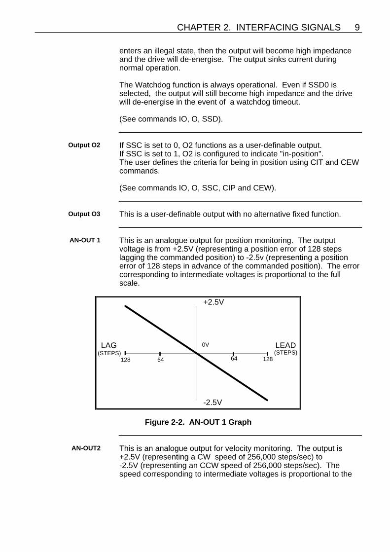
AN-OUT 1 This is an analogue output for position monitoring. The outputvoltage is from +2.5V (representing a position error of 128 stepslagging the commanded position) to -2.5v (representing a positionerror of 128 steps in advance of the commanded position). The errorcorresponding to intermediate voltages is proportional to the fullscale.
+2.5V
-2.5V
LEADLAG
128 128
0V
64(STEPS)
64(STEPS)
Figure 2-2. AN-OUT 1 Graph
AN-OUT2 This is an analogue output for velocity monitoring. The output is+2.5V (representing a CW speed of 256,000 steps/sec) to-2.5V (representing an CCW speed of 256,000 steps/sec). Thespeed corresponding to intermediate voltages is proportional to the

10 BL/BR SERVO DRIVE POSITIONER OPTION USER GUIDE
full scale.
+2.5V
-2.5V
256,000
0V(STEPS/SEC)
128,000(STEPS/SEC)
CLOCKWISE ANTICLOCKWISE
256,000128,000 0
Figure 2-3. AN-OUT 2 Graph
ControllerConnections
The RX input to accepts ASCII data from the controller at RS232Csignal levels.
The TX output sends ASCII data from the positioner to the controllerat RS232C signal levels.
The TXE and RXE connections are for connection to otherpositioners in the system using the Zero Delay Daisy Chain.
Encoder Connector With jumper links 1 to 6 on the adaptor board (see Figure 4-3) inposition B the positioner will respond to the encoder which is pluggedinto the Motor Feedback socket on the drive. With these jumper linksin position A, the positioner will respond to a separate encoder whichcan be connected to this socket.
InterfacingCircuit
Arrangements
This section describes some suitable circuits for interfacing to thepositioner.
Figure 2-4 shows the general circuit arrangement of the inputs andoutputs of the positioner. Both types of circuit are optically isolated togive immunity from noise and transients.

CHAPTER 2. INTERFACING SIGNALS 11
OPTO-ISOLATEDOPEN COLLECTOR OUTPUT
OUTPUT SINKSUP TO 300 MA
INTERFACE
OUTPUT INDICATOR LED
+24V IS.
IS, GND
ISOLATED24V 100mA
SUPPLYINPUT SWITCH
OPTO-COUPLERLED INPUT
6K8
2K2
POSITIONER EXTERNAL CIRCUITS
Figure 2-4. Inputs and Outputs - General Arrangement
Coupling OpticallyIsolated Outputs
and Inputs
An output can be coupled to an input on another positioner as shownin Figure 2-5.This connection may be required when runningsequences on two axes with a need to couple the two sequences.Using this arrangement, setting the output to 1 causes the opencollector output transistor to turn on, diverting current from the input.With no input current, the input is at 0 level, so a data inversionoccurs.
+24V ISOL
OUTPUT
24V ISOL GND 24V ISOL GND
INPUT
2K2
POSITIONER 1 POSITIONER 2
Figure 2-5. Input to Output Coupling

12 BL/BR SERVO DRIVE POSITIONER OPTION USER GUIDE
Clock and DirectionInputs
These balanced inputs may be driven from a single-ended output viaa differential line driver such as the National Semiconductor DS8830,which accepts a TTL level input and provides a balanced output.Each of the two circuits in the DS8830 should have their four inputsconnected together and to the input signal if this device is used (SeeFigure 2-6). Connecting the clock/direction source equipment groundto the positioner ground should be avoided since this would violatethe isolation conditions.
CLOCK
DIRECTION
5
6
9
8
123410111213
7
14
DS8830
+5V
0V
JOG-ESTPIS 24V
CLK+CLK-DIR+DIR-
AN OUT 1AN OUT 2GND
JOG+
Figure 2-6. Clock and Direction Inputs
Limit and HomeInputs
Both limit inputs are optically-isolated, requiring to be connected to+24V when they are not operational. If disconnected or taken to 0V,they are operational and will prevent movement of the axis. Twomethods of switching these inputs are shown in Figures 2-7 and 2-8.NPN proximity switches and mechanical switches are the examplesshown. The limits can be disabled with the LD3 command.
The GO HOME function of the positioner is initiated by issuing theGO HOME (GH) command. When the command is issued, thedirection in which it should search for home and the velocity must beincluded.
(See the GA, SS, SR, GHP and GHF commands).
CHAPTER 2. INTERFACING SIGNALS 13
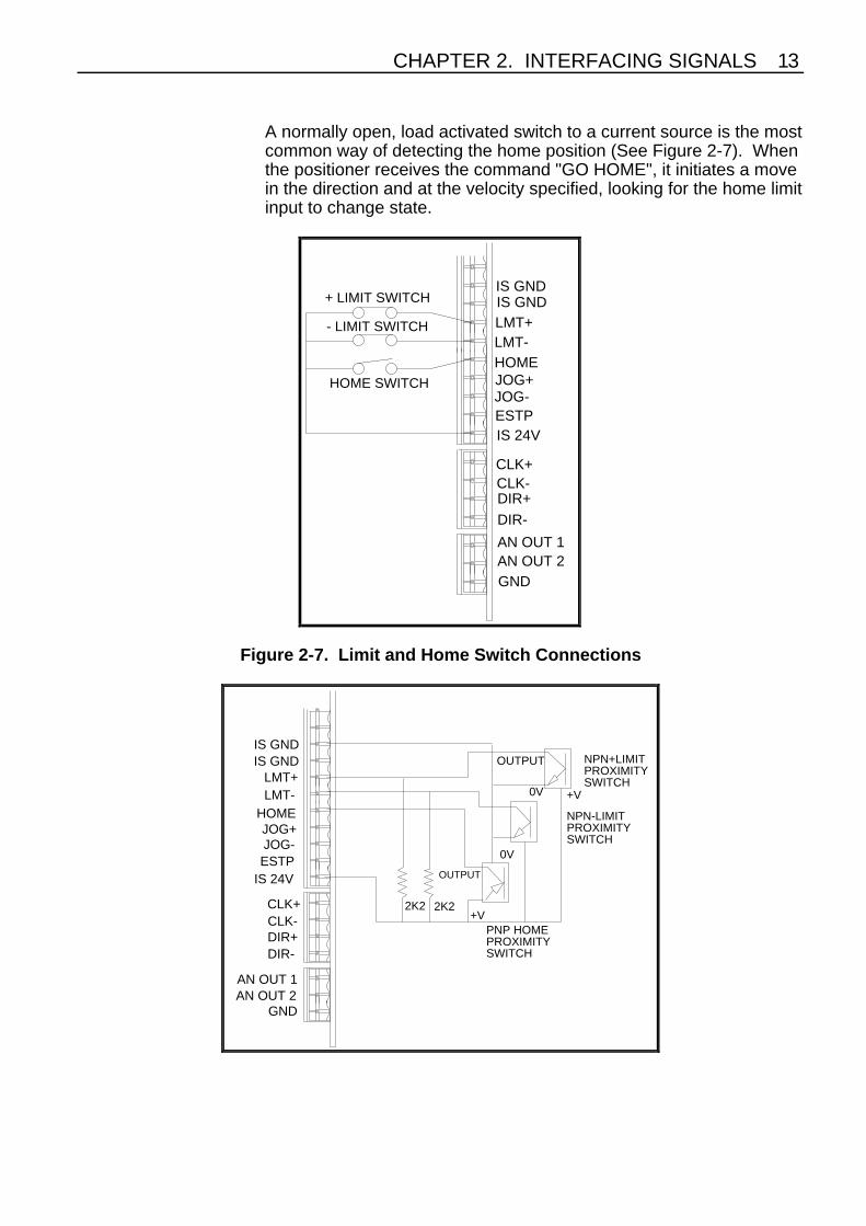
A normally open, load activated switch to a current source is the mostcommon way of detecting the home position (See Figure 2-7). Whenthe positioner receives the command "GO HOME", it initiates a movein the direction and at the velocity specified, looking for the home limitinput to change state.
+ LIMIT SWITCH
- LIMIT SWITCH
HOME SWITCH
IS GNDIS GNDLMT+LMT-HOMEJOG+JOG-ESTPIS 24V
CLK+CLK-DIR+
DIR-
AN OUT 1AN OUT 2GND
Figure 2-7. Limit and Home Switch Connections
NPN+LIMITPROXIMITYSWITCH
NPN-LIMITPROXIMITYSWITCH
PNP HOMEPROXIMITYSWITCH
OUTPUT
0V +V
+V
OUTPUT
0V
2K2 2K2
IS GNDIS GND
LMT+LMT-
HOMEJOG+JOG-ESTP
IS 24V
CLK+CLK-DIR+DIR-
AN OUT 1AN OUT 2
GND

14 BL/BR SERVO DRIVE POSITIONER OPTION USER GUIDE
Figure 2-8. Limit and Home Proximity
Note the NPN limit switches shown in Figure 2-8 are normally open(the limit input is held inactive by the additional 2K2 resistorconnected to the isolated +24V supply). Once a limit is reached theNPN transistor will turn ON, activating the limit input. Table 2-2provides a summary of switch types for use as Home or EOTswitching.
Usage Logic Switch typeHOME PNP N.O.
NPN N.C. use external resistorEND OF TRAVEL PNP N.C
NPN N.O. use external resistor
Table 2-2. Switch Type Selection
ESTOP Input The ESTOP input must have current sourced to it to keep the driveenergised. It is usually connected to the +24V supply via a normallyclosed push button as shown in Figure 2-9. If the push-button ispressed, the drive immediately de-energises.
IS GNDIS GND
LMT+LMT-
HOMEJOG+JOG-ESTP
IS 24V
CLK+CLK-DIR+DIR-
AN OUT 1AN OUT 2
GND
ESTOP
PUSHBUTTON
Figure 2-9. ESTOP Switch Connection
Trigger Inputs The positioner has thirteen optically isolated inputs, any of which maybe used as triggers with, for example, the TRE command.

CHAPTER 2. INTERFACING SIGNALS 15
The semi-dedicated inputs such as + and - jog must have theirdedicated functions disabled when used as trigger inputs. They maybe used either high true or low true but you must supply the inputswith 7 to 24 volts at 4mA per input to turn on the opto-isolators.Theisolated 24V supply available at the edge connector may be used asshown in Figure 2-10.
OPTO-ISOLATED
POSITIONER
+24V IS
IS, GND
ISOLATED24V 100mA
SUPPLY
INPUT SWITCHOPTO-COUPLERLED INPUT
+24V
TRIGGER
4mA6K8
Figure 2-10. Trigger Input Connection
16 BL/BR SERVO DRIVE POSITIONER OPTION USER GUIDE
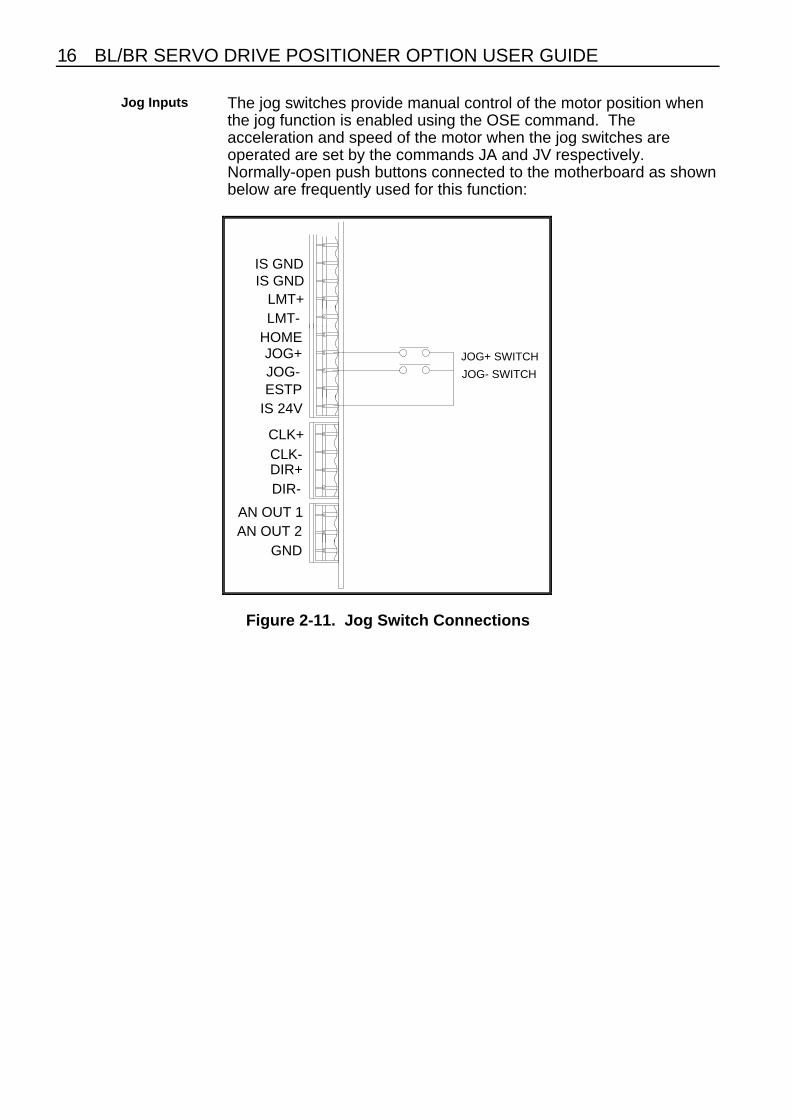
Jog Inputs The jog switches provide manual control of the motor position whenthe jog function is enabled using the OSE command. Theacceleration and speed of the motor when the jog switches areoperated are set by the commands JA and JV respectively.Normally-open push buttons connected to the motherboard as shownbelow are frequently used for this function:
JOG+ SWITCH
JOG- SWITCH
IS GNDIS GND
LMT+LMT-
HOMEJOG+JOG-ESTP
IS 24V
CLK+CLK-DIR+DIR-
AN OUT 1AN OUT 2
GND
Figure 2-11. Jog Switch Connections
CHAPTER 2. INTERFACING SIGNALS 17
Composite FaultIndicator
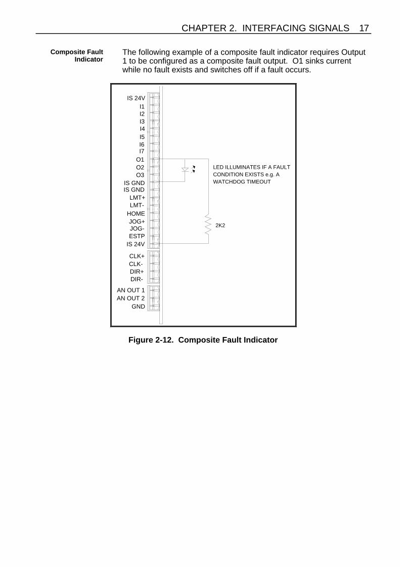
The following example of a composite fault indicator requires Output1 to be configured as a composite fault output. O1 sinks currentwhile no fault exists and switches off if a fault occurs.
IS 24VI1I2I3I4I5I6I7
O1O2O3
IS GNDIS GND
LMT+LMT-
HOMEJOG+JOG-ESTP
IS 24V
CLK+CLK-DIR+DIR-
AN OUT 1AN OUT 2
GND
LED ILLUMINATES IF A FAULTCONDITION EXISTS e.g. AWATCHDOG TIMEOUT
2K2
Figure 2-12. Composite Fault Indicator
18 BL/BR SERVO DRIVE POSITIONER OPTION USER GUIDE
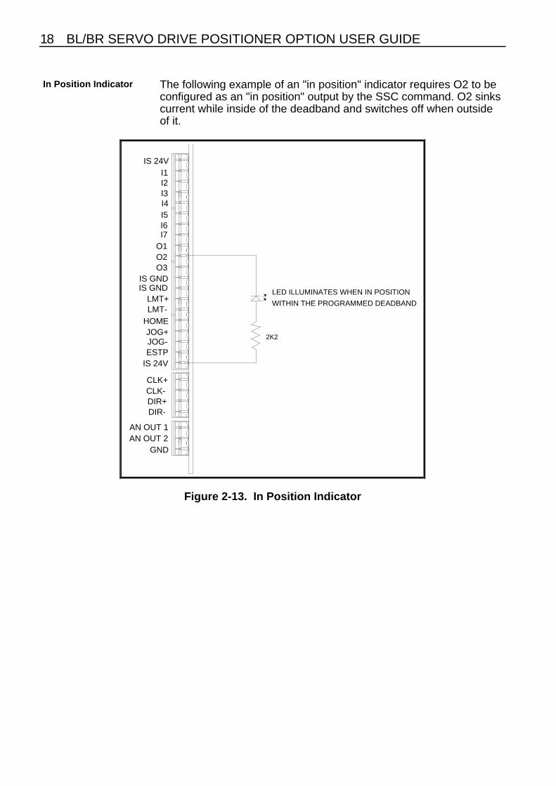
In Position Indicator The following example of an "in position" indicator requires O2 to beconfigured as an "in position" output by the SSC command. O2 sinkscurrent while inside of the deadband and switches off when outsideof it.
2K2
LED ILLUMINATES WHEN IN POSITION
WITHIN THE PROGRAMMED DEADBAND
IS 24VI1I2I3I4I5I6I7
O1O2O3
IS GNDIS GND
LMT+LMT-
HOMEJOG+JOG-ESTP
IS 24V
CLK+CLK-DIR+DIR-
AN OUT 1AN OUT 2
GND
Figure 2-13. In Position Indicator
Top Related