


Languages
Pages
Legal

Copyright © 2018 UUGear s.r.o. All rights reserved.
BIG7 USB Hub (Rev 2) for Raspberry Pi
User Manual
Copyright © 2018 UUGear s.r.o. All rights reserved.
Table of Content
Product Overview ............................................................................................... 1
Package Content ................................................................................................ 4
Specifications ..................................................................................................... 5
About Back-Power (Back Feeding Power) .......................................................... 6
About Powering Mode ........................................................................................ 6
Bus-Power Mode......................................................................................... 6
Self-Power Mode......................................................................................... 7
About MTT and STT ........................................................................................... 7
Usage Guide ...................................................................................................... 8
Raspberry Pi Model A and B ....................................................................... 8
Raspberry Pi B+, Raspberry Pi 2 and Raspberry Pi 3 (B Model) ................ 11
Raspberry Pi A+ ........................................................................................ 17
Raspberry Pi Compute Module (with Development Kit) ............................. 19
Raspberry Pi Zero ..................................................................................... 21
Monitoring USB Port Usage ............................................................................. 23
Controlling the Power for USB Ports ................................................................ 24
Integrates with Witty Pi 2 .................................................................................. 26
Integrates with Zero2Go ................................................................................... 30
1
Product Overview
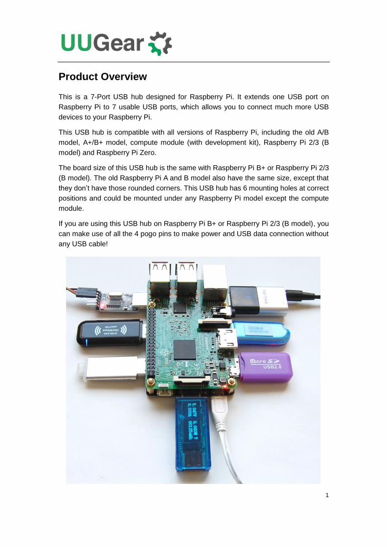
This is a 7-Port USB hub designed for Raspberry Pi. It extends one USB port on
Raspberry Pi to 7 usable USB ports, which allows you to connect much more USB
devices to your Raspberry Pi.
This USB hub is compatible with all versions of Raspberry Pi, including the old A/B
model, A+/B+ model, compute module (with development kit), Raspberry Pi 2/3 (B
model) and Raspberry Pi Zero.
The board size of this USB hub is the same with Raspberry Pi B+ or Raspberry Pi 2/3
(B model). The old Raspberry Pi A and B model also have the same size, except that
they don’t have those rounded corners. This USB hub has 6 mounting holes at correct
positions and could be mounted under any Raspberry Pi model except the compute
module.
If you are using this USB hub on Raspberry Pi B+ or Raspberry Pi 2/3 (B model), you
can make use of all the 4 pogo pins to make power and USB data connection without
any USB cable!
2
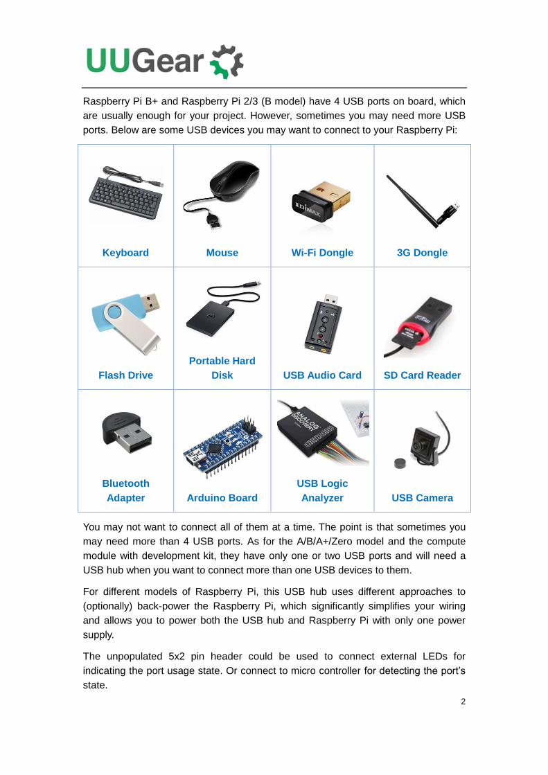
Raspberry Pi B+ and Raspberry Pi 2/3 (B model) have 4 USB ports on board, which
are usually enough for your project. However, sometimes you may need more USB
ports. Below are some USB devices you may want to connect to your Raspberry Pi:
Keyboard
Mouse
Wi-Fi Dongle
3G Dongle
Flash Drive
Portable Hard
Disk
USB Audio Card
SD Card Reader
Bluetooth
Adapter
Arduino Board
USB Logic
Analyzer
USB Camera
You may not want to connect all of them at a time. The point is that sometimes you
may need more than 4 USB ports. As for the A/B/A+/Zero model and the compute
module with development kit, they have only one or two USB ports and will need a
USB hub when you want to connect more than one USB devices to them.
For different models of Raspberry Pi, this USB hub uses different approaches to
(optionally) back-power the Raspberry Pi, which significantly simplifies your wiring
and allows you to power both the USB hub and Raspberry Pi with only one power
supply.
The unpopulated 5x2 pin header could be used to connect external LEDs for
indicating the port usage state. Or connect to micro controller for detecting the port’s
state.
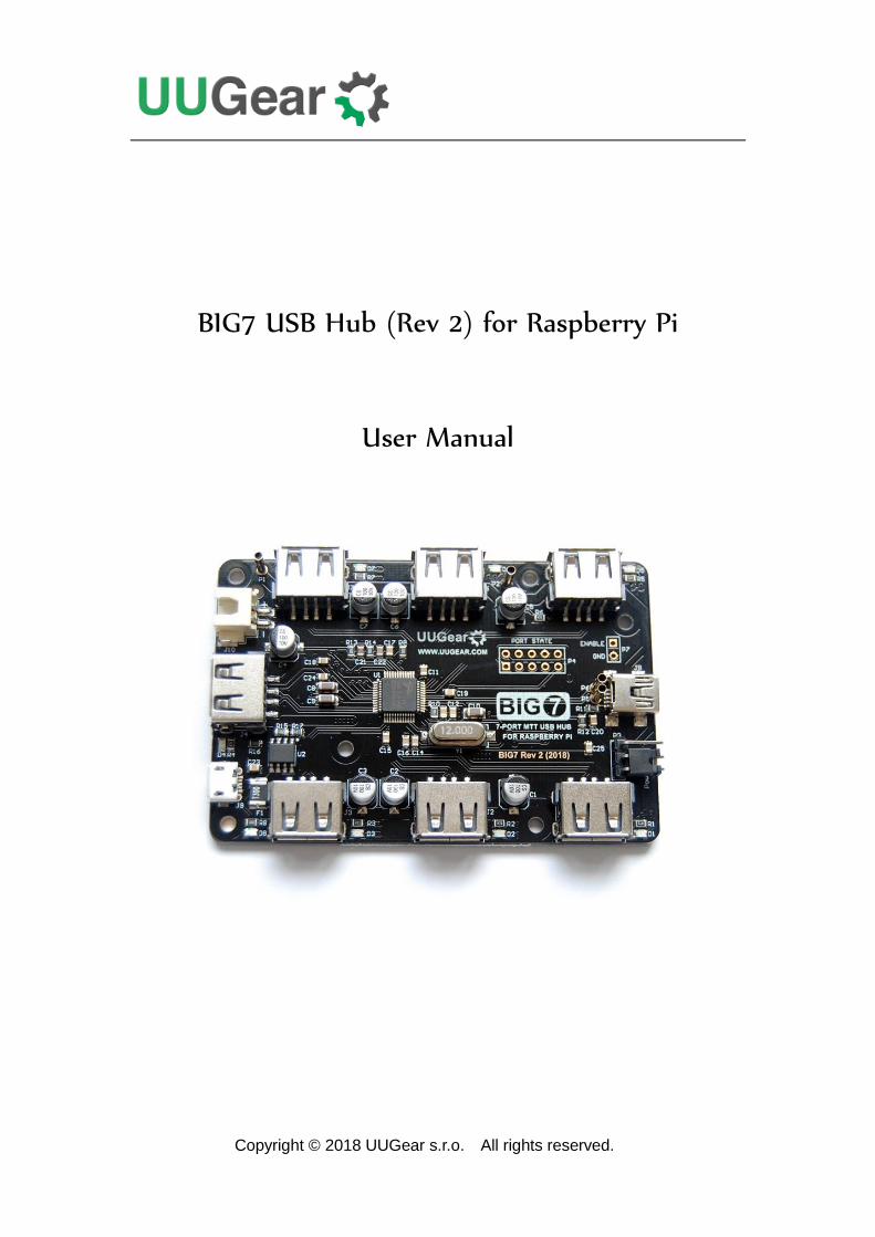
3
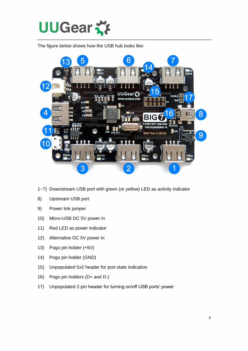
The figure below shows how the USB hub looks like:
1~7) Downstream USB port with green (or yellow) LED as activity indicator
8) Upstream USB port
9) Power link jumper
10) Micro-USB DC 5V power in
11) Red LED as power indicator
12) Alternative DC 5V power in
13) Pogo pin holder (+5V)
14) Pogo pin holder (GND)
15) Unpopulated 5x2 header for port state indication
16) Pogo pin holders (D+ and D-)
17) Unpopulated 2-pin header for turning on/off USB ports’ power
4
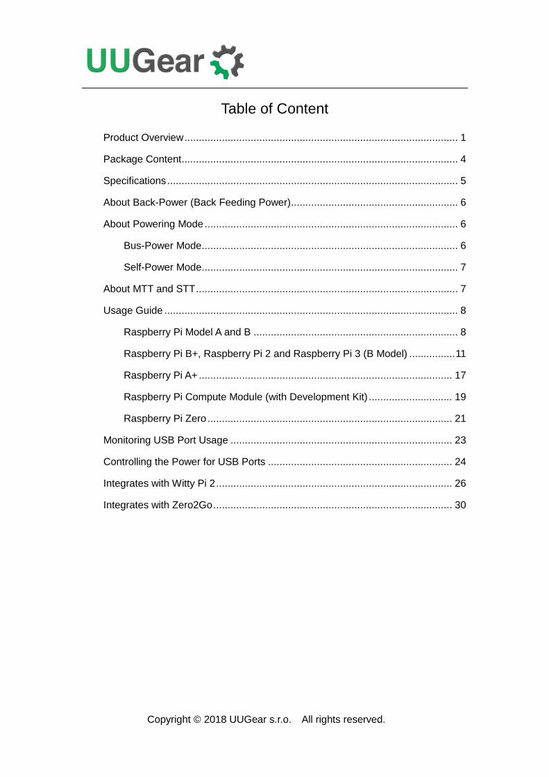
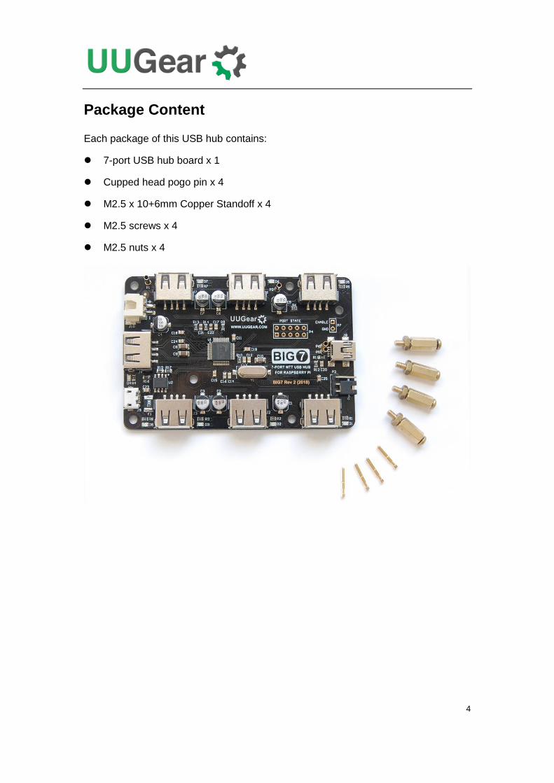
Package Content
Each package of this USB hub contains:
7-port USB hub board x 1
Cupped head pogo pin x 4
M2.5 x 10+6mm Copper Standoff x 4
M2.5 screws x 4
M2.5 nuts x 4
5
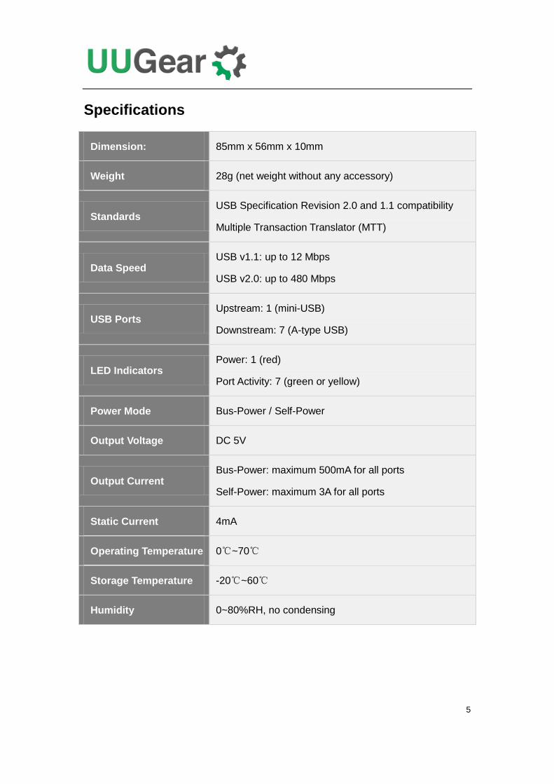
Specifications
Dimension: 85mm x 56mm x 10mm
Weight 28g (net weight without any accessory)
Standards USB Specification Revision 2.0 and 1.1 compatibility
Multiple Transaction Translator (MTT)
Data Speed USB v1.1: up to 12 Mbps
USB v2.0: up to 480 Mbps
USB Ports Upstream: 1 (mini-USB)
Downstream: 7 (A-type USB)
LED Indicators Power: 1 (red)
Port Activity: 7 (green or yellow)
Power Mode Bus-Power / Self-Power
Output Voltage DC 5V
Output Current Bus-Power: maximum 500mA for all ports
Self-Power: maximum 3A for all ports
Static Current 4mA
Operating Temperature 0℃~70℃
Storage Temperature -20℃~60℃
Humidity 0~80%RH, no condensing
6
About Back-Power (Back Feeding Power)
Back-power (or back feeding power) here means the USB hub provides electronic
power to Raspberry Pi. This can only (optionally) happen when the USB hub gets
power supply connected (works in self-power mode). The advantage of back-power is
that you only need one power supply to power both the USB hub and Raspberry Pi.
Someone may not like the back-power, but it actually works without problem unless
you connect two power supplies and let them fight with each other. So if you choose
back-powering, make sure you only connect one power supply to the USB hub, and
do not connect any power supply to the micro USB port on Raspberry Pi.
Some models of Raspberry Pi allow back-powering via the USB port, but some do not.
There are two pogo pins in the package and they could be used to back-power
Raspberry Pi via the 40-pin GPIO header, when back-powering via USB is not
supported by Raspberry Pi.
About Powering Mode
A USB hub could be powered by the USB bus (bus-power mode), or be powered by
the power supply (self-power mode). Bus-power mode is simpler as it does not need
to have external power supply, but it has quite limited ability to power the devices on
the USB hub. When you are trying to power more devices with higher current, it is
recommended to use the self-power mode.
This USB hub supports both bus-power mode and self-power mode.
Bus-Power Mode
If you only connect USB devices that consume very small current to the USB hub, you
can consider using the bus-power mode. Just make sure the jumper is at “power link”
position (which is the default setting) and do not connect power supply to the USB
hub.
When you use a USB - miniUSB cable to connect a USB port on Raspberry Pi and the
upstream USB port on the USB hub, the USB hub will be powered too (taking power
from the USB bus). In this case, the USB hub is working in bus-power mode, and the
maximum output current for all ports are 500mA, according to the USB standard.
Remarks: If you are using the first revision of Raspberry Pi A/B, each USB port on it
has a 140mA polyfuse, which will reduce the maximum output current to about 100mA.
In this case, it is strongly recommended to use the self-power mode instead.

7
Self-Power Mode
If you connect the power supply to the micro USB port (power in) on the USB hub, the
USB hub will work in self-power mode, or say it becomes a powered USB hub. In this
case the maximum output current for all USB ports are 2,600mA.
If the USB hub is also back-powering your Raspberry Pi, the current consumed by
Raspberry Pi is also taken into account. For example, if Raspberry Pi consumes
260mA, then the maximum output current for all USB ports will become 2,340mA.
About MTT and STT
A USB hub may have two possible ways for organizing Transaction Translators (TTs).
A USB hub could have one TT for all downstream ports that have USB devices
attached (which is called Single Transaction Translator, STT), or the USB hub could
have one TT for each downstream port (which is called Multiple Transaction
Translator, MTT) .
For Single Transaction Translator (STT), connecting one USB 1.1 device to the hub
will force all ports to process data with USB 1.1 standard, thus slowing down all USB
devices on the same USB hub. While for Multiple Transaction Translator (MTT), each
downstream port has its own transaction translator to provide the best USB
performance no matter what class of USB device is connected.
So MTT is better than STT, if the higher price is acceptable.
This USB hub has Multiple Transaction Translator (MTT).
8
Usage Guide
This USB hub can work with all models of Raspberry Pi. However, the mounting and
wiring may be different for various models. Please read the sections below for details.
Raspberry Pi Model A and B
The old models of Raspberry Pi (A and B model) only have two mounting holes, so we
only need two sets of copper standoff, screw and nut to mount the USB hub under it.
The pogo pins should not be used in this case.
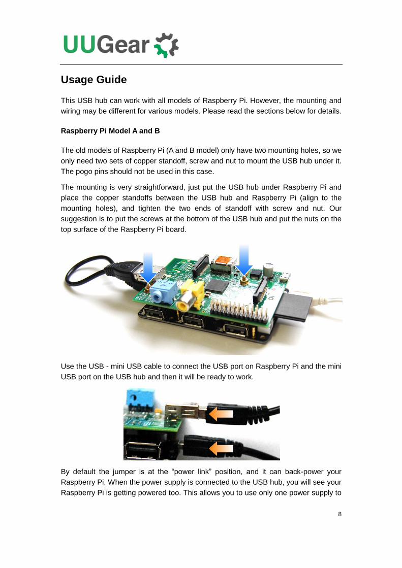
The mounting is very straightforward, just put the USB hub under Raspberry Pi and
place the copper standoffs between the USB hub and Raspberry Pi (align to the
mounting holes), and tighten the two ends of standoff with screw and nut. Our
suggestion is to put the screws at the bottom of the USB hub and put the nuts on the
top surface of the Raspberry Pi board.
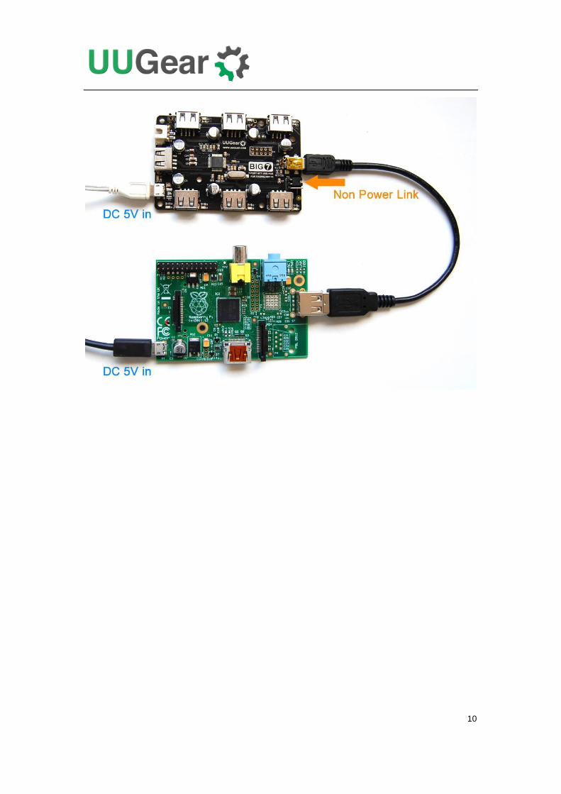
Use the USB - mini USB cable to connect the USB port on Raspberry Pi and the mini
USB port on the USB hub and then it will be ready to work.
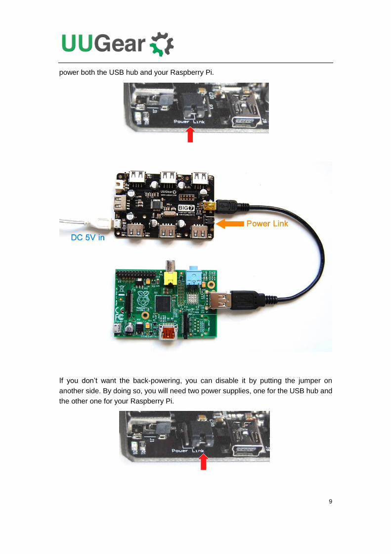
By default the jumper is at the “power link” position, and it can back-power your
Raspberry Pi. When the power supply is connected to the USB hub, you will see your
Raspberry Pi is getting powered too. This allows you to use only one power supply to
9
power both the USB hub and your Raspberry Pi.
If you don’t want the back-powering, you can disable it by putting the jumper on
another side. By doing so, you will need two power supplies, one for the USB hub and
the other one for your Raspberry Pi.
10
11
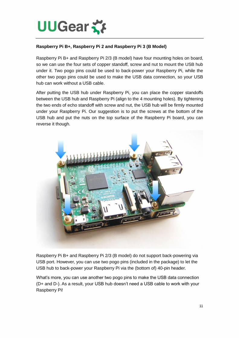
Raspberry Pi B+, Raspberry Pi 2 and Raspberry Pi 3 (B Model)
Raspberry Pi B+ and Raspberry Pi 2/3 (B model) have four mounting holes on board,
so we can use the four sets of copper standoff, screw and nut to mount the USB hub
under it. Two pogo pins could be used to back-power your Raspberry Pi, while the
other two pogo pins could be used to make the USB data connection, so your USB
hub can work without a USB cable.
After putting the USB hub under Raspberry Pi, you can place the copper standoffs
between the USB hub and Raspberry Pi (align to the 4 mounting holes). By tightening
the two ends of echo standoff with screw and nut, the USB hub will be firmly mounted
under your Raspberry Pi. Our suggestion is to put the screws at the bottom of the
USB hub and put the nuts on the top surface of the Raspberry Pi board, you can
reverse it though.
Raspberry Pi B+ and Raspberry Pi 2/3 (B model) do not support back-powering via
USB port. However, you can use two pogo pins (included in the package) to let the
USB hub to back-power your Raspberry Pi via the (bottom of) 40-pin header.
What’s more, you can use another two pogo pins to make the USB data connection
(D+ and D-). As a result, your USB hub doesn’t need a USB cable to work with your
Raspberry Pi!
12
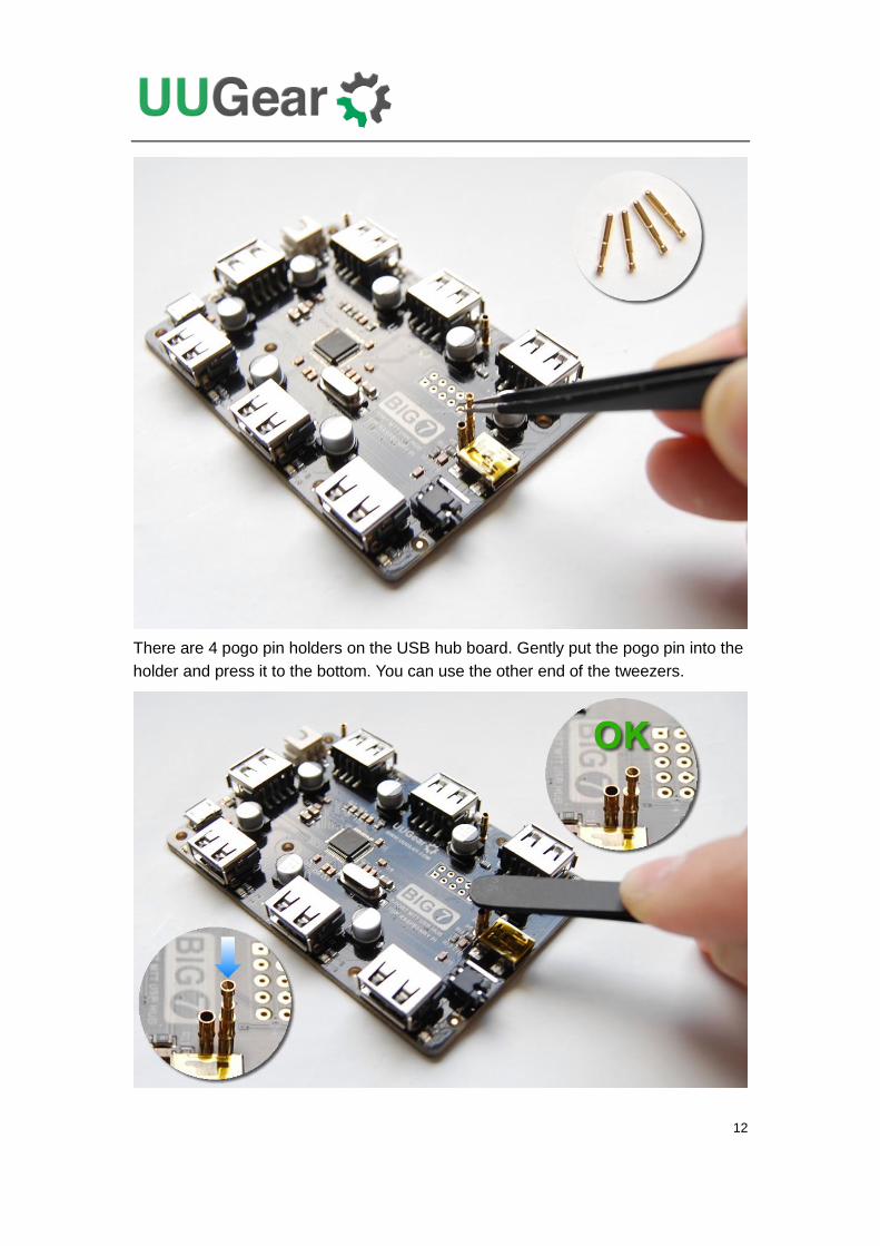
There are 4 pogo pin holders on the USB hub board. Gently put the pogo pin into the
holder and press it to the bottom. You can use the other end of the tweezers.
13
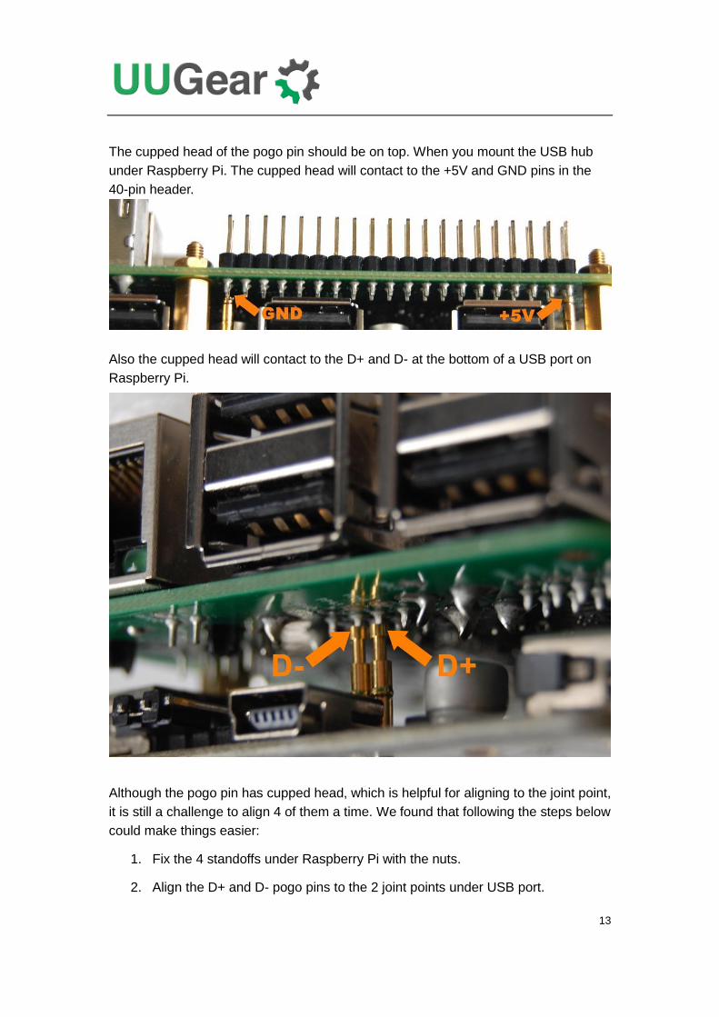
The cupped head of the pogo pin should be on top. When you mount the USB hub
under Raspberry Pi. The cupped head will contact to the +5V and GND pins in the
40-pin header.
Also the cupped head will contact to the D+ and D- at the bottom of a USB port on
Raspberry Pi.
Although the pogo pin has cupped head, which is helpful for aligning to the joint point,
it is still a challenge to align 4 of them a time. We found that following the steps below
could make things easier:
1. Fix the 4 standoffs under Raspberry Pi with the nuts.
2. Align the D+ and D- pogo pins to the 2 joint points under USB port.
14
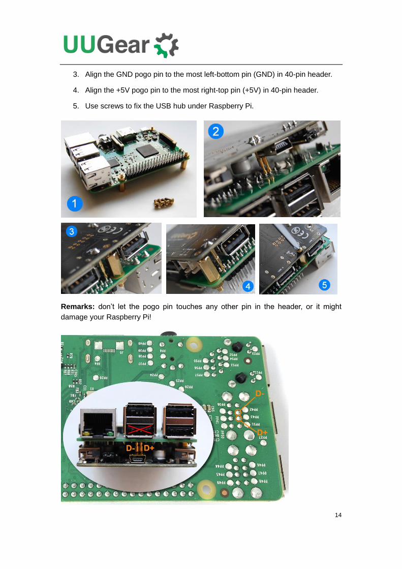
3. Align the GND pogo pin to the most left-bottom pin (GND) in 40-pin header.
4. Align the +5V pogo pin to the most right-top pin (+5V) in 40-pin header.
5. Use screws to fix the USB hub under Raspberry Pi.
Remarks: don’t let the pogo pin touches any other pin in the header, or it might
damage your Raspberry Pi!
15
In the figure above you can see the actual position of the D+ and D- joint points. After
mounting the USB hub under Raspberry Pi, one USB port on Raspberry Pi is taken by
the USB hub (as upstream port) and it could not be used by other USB devices.
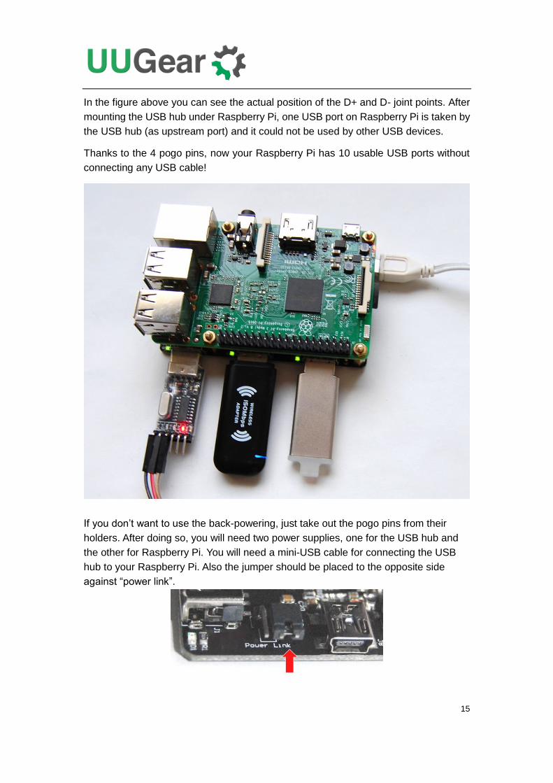
Thanks to the 4 pogo pins, now your Raspberry Pi has 10 usable USB ports without
connecting any USB cable!
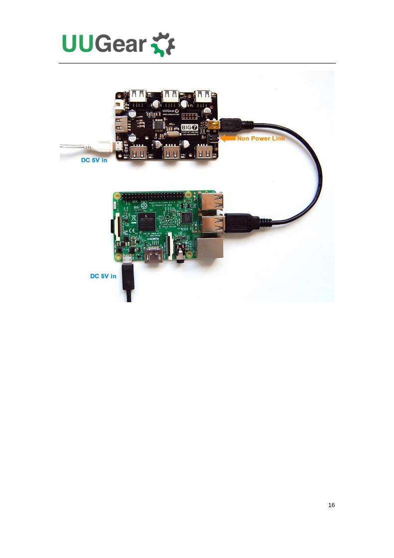
If you don’t want to use the back-powering, just take out the pogo pins from their
holders. After doing so, you will need two power supplies, one for the USB hub and
the other for Raspberry Pi. You will need a mini-USB cable for connecting the USB
hub to your Raspberry Pi. Also the jumper should be placed to the opposite side
against “power link”.
16
17
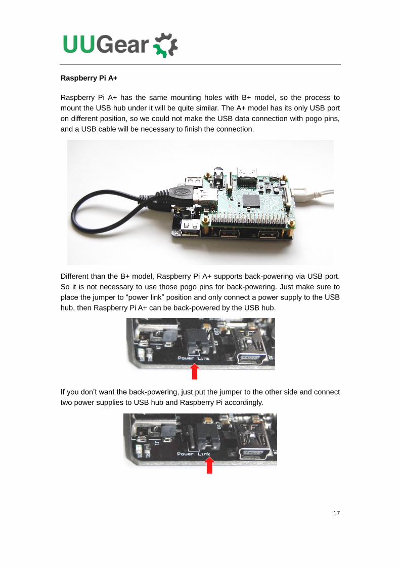
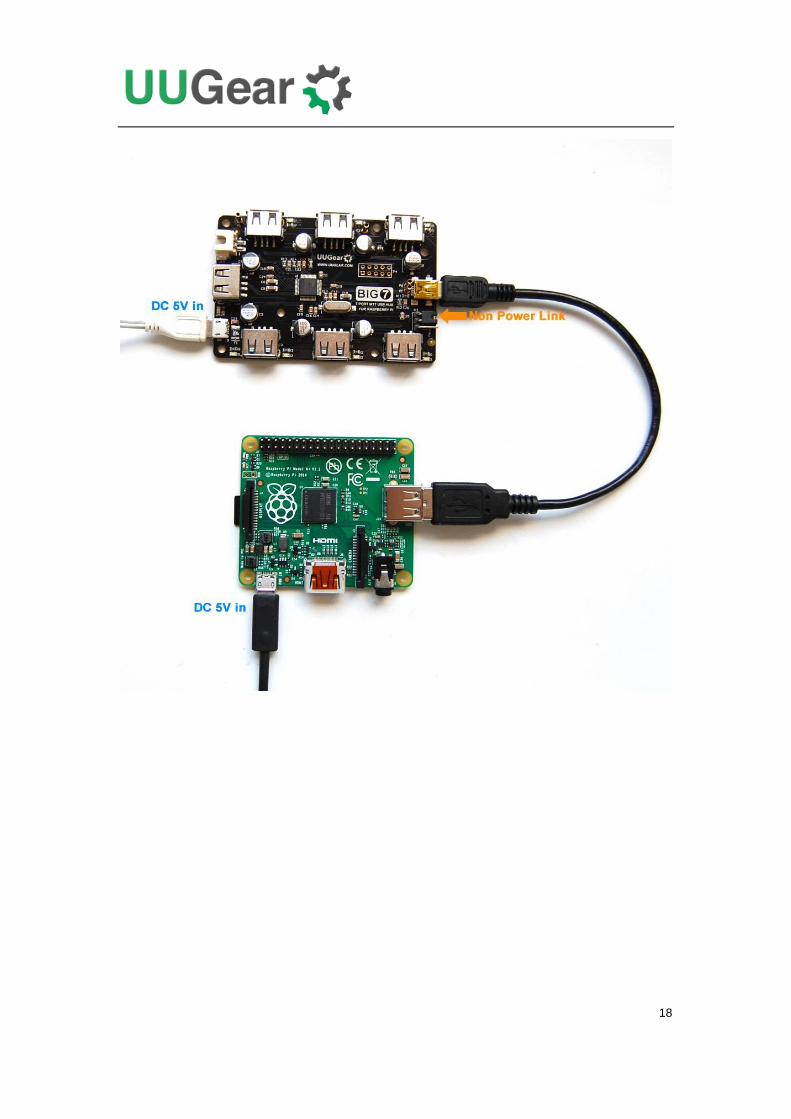
Raspberry Pi A+
Raspberry Pi A+ has the same mounting holes with B+ model, so the process to
mount the USB hub under it will be quite similar. The A+ model has its only USB port
on different position, so we could not make the USB data connection with pogo pins,
and a USB cable will be necessary to finish the connection.
Different than the B+ model, Raspberry Pi A+ supports back-powering via USB port.
So it is not necessary to use those pogo pins for back-powering. Just make sure to
place the jumper to “power link” position and only connect a power supply to the USB
hub, then Raspberry Pi A+ can be back-powered by the USB hub.
If you don’t want the back-powering, just put the jumper to the other side and connect
two power supplies to USB hub and Raspberry Pi accordingly.
18
19
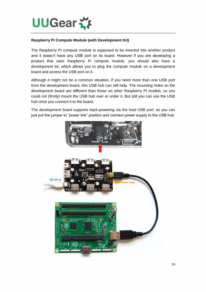
Raspberry Pi Compute Module (with Development Kit)
The Raspberry Pi compute module is supposed to be inserted into another product
and it doesn’t have any USB port on its board. However if you are developing a
product that uses Raspberry Pi compute module, you should also have a
development kit, which allows you to plug the compute module on a development
board and access the USB port on it.
Although it might not be a common situation, if you need more than one USB port
from the development board, this USB hub can still help. The mounting holes on the
development board are different than those on other Raspberry Pi models, so you
could not (firmly) mount the USB hub over or under it. But still you can use the USB
hub once you connect it to the board.
The development board supports back-powering via the host USB port, so you can
just put the jumper to “power link” position and connect power supply to the USB hub.
20
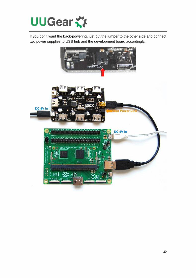
If you don’t want the back-powering, just put the jumper to the other side and connect
two power supplies to USB hub and the development board accordingly.
21
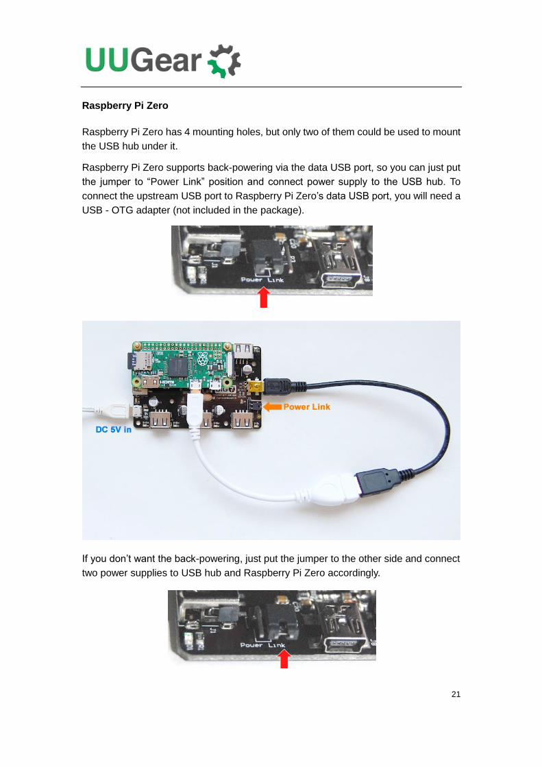
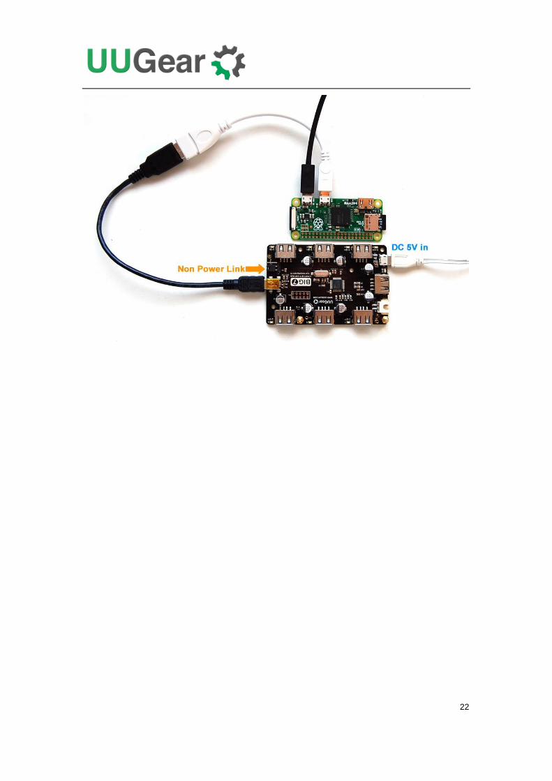
Raspberry Pi Zero
Raspberry Pi Zero has 4 mounting holes, but only two of them could be used to mount
the USB hub under it.
Raspberry Pi Zero supports back-powering via the data USB port, so you can just put
the jumper to “Power Link” position and connect power supply to the USB hub. To
connect the upstream USB port to Raspberry Pi Zero’s data USB port, you will need a
USB - OTG adapter (not included in the package).
If you don’t want the back-powering, just put the jumper to the other side and connect
two power supplies to USB hub and Raspberry Pi Zero accordingly.
22
23
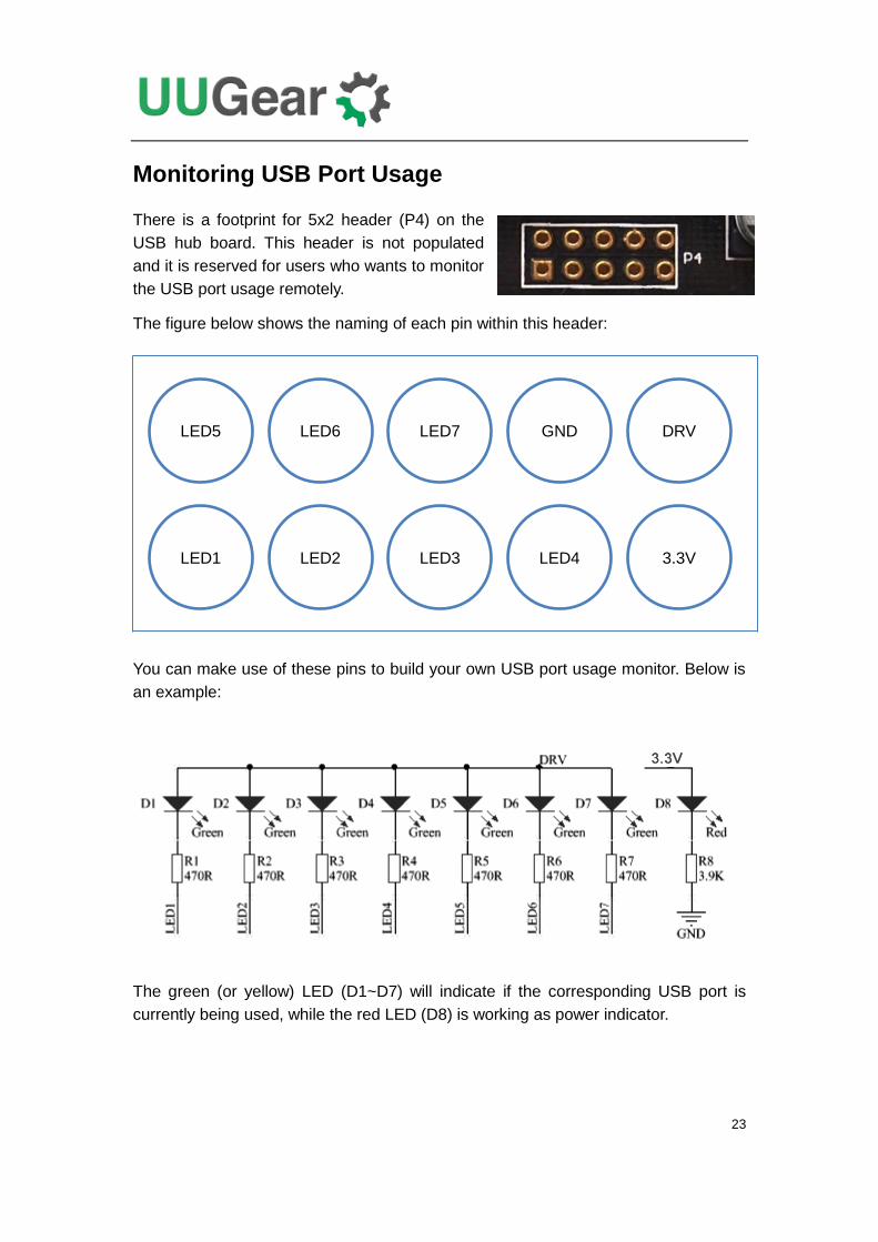
Monitoring USB Port Usage
There is a footprint for 5x2 header (P4) on the
USB hub board. This header is not populated
and it is reserved for users who wants to monitor
the USB port usage remotely.
The figure below shows the naming of each pin within this header:
You can make use of these pins to build your own USB port usage monitor. Below is
an example:
The green (or yellow) LED (D1~D7) will indicate if the corresponding USB port is
currently being used, while the red LED (D8) is working as power indicator.
LED5 LED6 DRV GND LED7
LED1 LED2 3.3V LED4 LED3
24
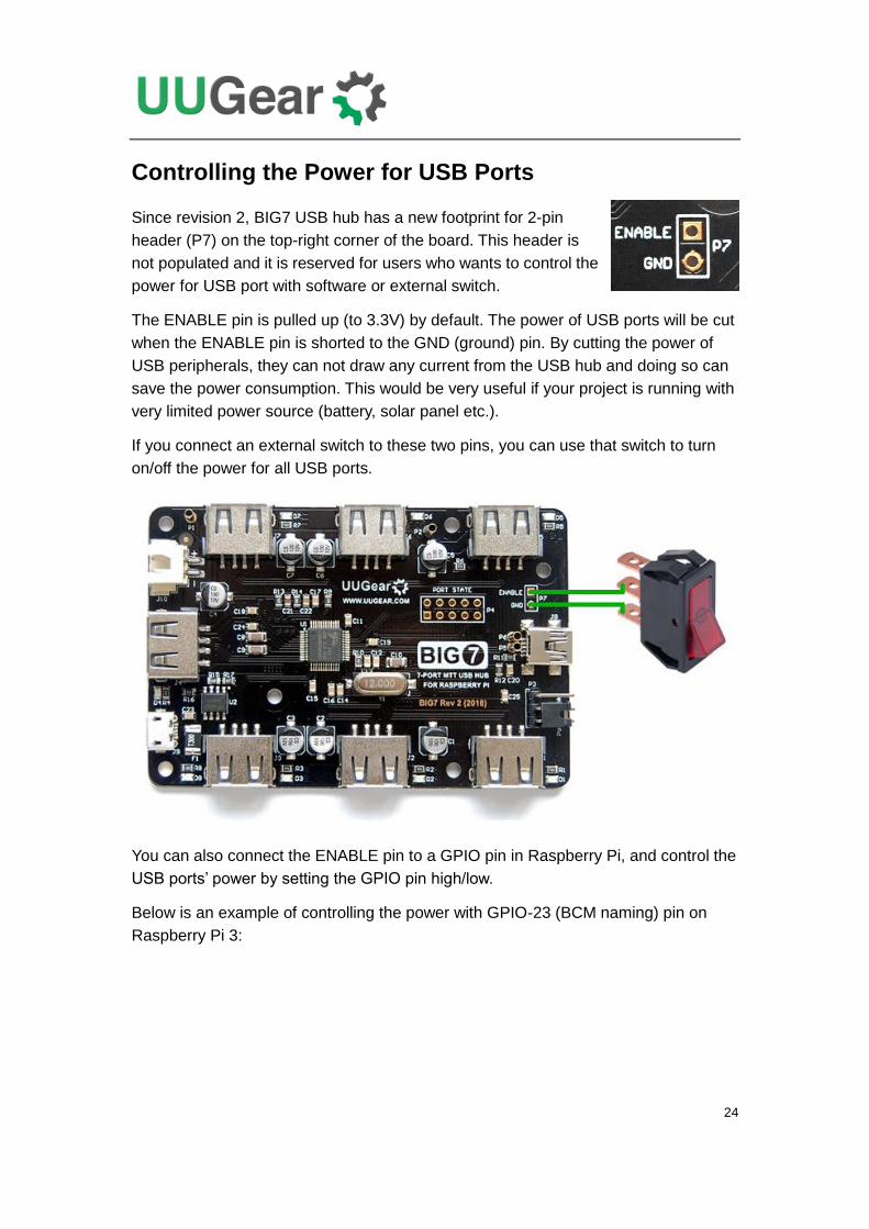
Controlling the Power for USB Ports
Since revision 2, BIG7 USB hub has a new footprint for 2-pin
header (P7) on the top-right corner of the board. This header is
not populated and it is reserved for users who wants to control the
power for USB port with software or external switch.
The ENABLE pin is pulled up (to 3.3V) by default. The power of USB ports will be cut
when the ENABLE pin is shorted to the GND (ground) pin. By cutting the power of
USB peripherals, they can not draw any current from the USB hub and doing so can
save the power consumption. This would be very useful if your project is running with
very limited power source (battery, solar panel etc.).
If you connect an external switch to these two pins, you can use that switch to turn
on/off the power for all USB ports.
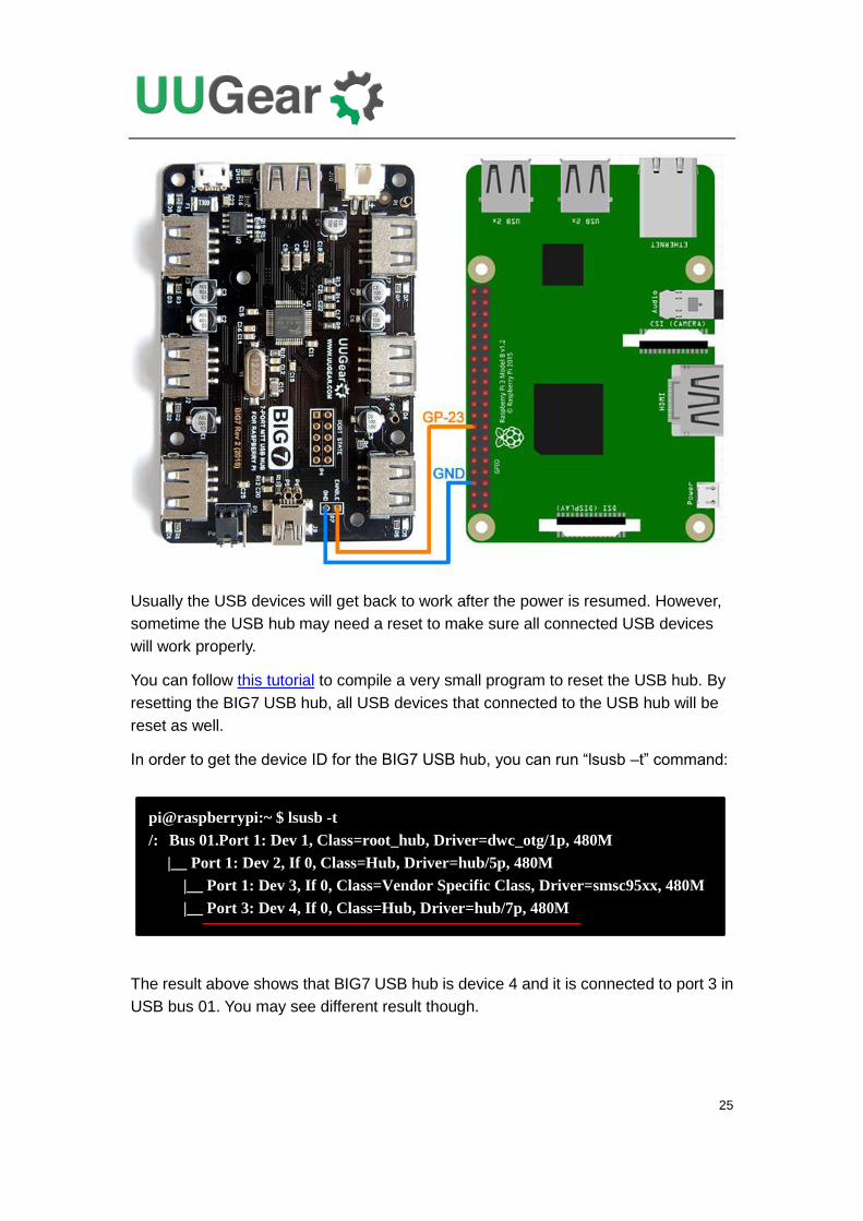
You can also connect the ENABLE pin to a GPIO pin in Raspberry Pi, and control the
USB ports’ power by setting the GPIO pin high/low.
Below is an example of controlling the power with GPIO-23 (BCM naming) pin on
Raspberry Pi 3:
25
Usually the USB devices will get back to work after the power is resumed. However,
sometime the USB hub may need a reset to make sure all connected USB devices
will work properly.
You can follow this tutorial to compile a very small program to reset the USB hub. By
resetting the BIG7 USB hub, all USB devices that connected to the USB hub will be
reset as well.
In order to get the device ID for the BIG7 USB hub, you can run “lsusb –t” command:
The result above shows that BIG7 USB hub is device 4 and it is connected to port 3 in
USB bus 01. You may see different result though.
pi@raspberrypi:~ $ lsusb -t
/: Bus 01.Port 1: Dev 1, Class=root_hub, Driver=dwc_otg/1p, 480M
|__ Port 1: Dev 2, If 0, Class=Hub, Driver=hub/5p, 480M
|__ Port 1: Dev 3, If 0, Class=Vendor Specific Class, Driver=smsc95xx, 480M
|__ Port 3: Dev 4, If 0, Class=Hub, Driver=hub/7p, 480M
26
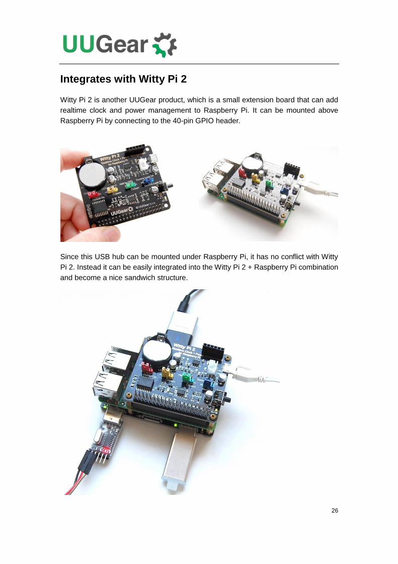
Integrates with Witty Pi 2
Witty Pi 2 is another UUGear product, which is a small extension board that can add
realtime clock and power management to Raspberry Pi. It can be mounted above
Raspberry Pi by connecting to the 40-pin GPIO header.
Since this USB hub can be mounted under Raspberry Pi, it has no conflict with Witty
Pi 2. Instead it can be easily integrated into the Witty Pi 2 + Raspberry Pi combination
and become a nice sandwich structure.
27
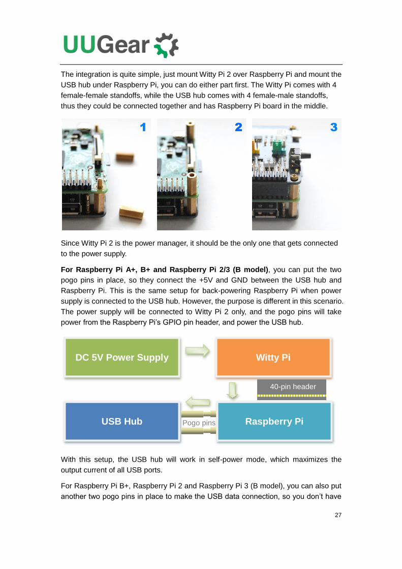
The integration is quite simple, just mount Witty Pi 2 over Raspberry Pi and mount the
USB hub under Raspberry Pi, you can do either part first. The Witty Pi comes with 4
female-female standoffs, while the USB hub comes with 4 female-male standoffs,
thus they could be connected together and has Raspberry Pi board in the middle.
Since Witty Pi 2 is the power manager, it should be the only one that gets connected
to the power supply.
For Raspberry Pi A+, B+ and Raspberry Pi 2/3 (B model), you can put the two
pogo pins in place, so they connect the +5V and GND between the USB hub and
Raspberry Pi. This is the same setup for back-powering Raspberry Pi when power
supply is connected to the USB hub. However, the purpose is different in this scenario.
The power supply will be connected to Witty Pi 2 only, and the pogo pins will take
power from the Raspberry Pi’s GPIO pin header, and power the USB hub.
With this setup, the USB hub will work in self-power mode, which maximizes the
output current of all USB ports.
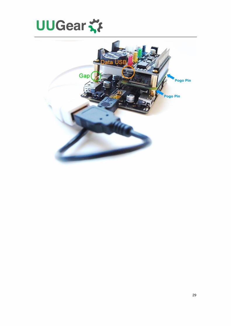
For Raspberry Pi B+, Raspberry Pi 2 and Raspberry Pi 3 (B model), you can also put
another two pogo pins in place to make the USB data connection, so you don’t have
DC 5V Power Supply
Raspberry Pi USB Hub
Witty Pi
40-pin header
Pogo pins
28
to use the USB cable.
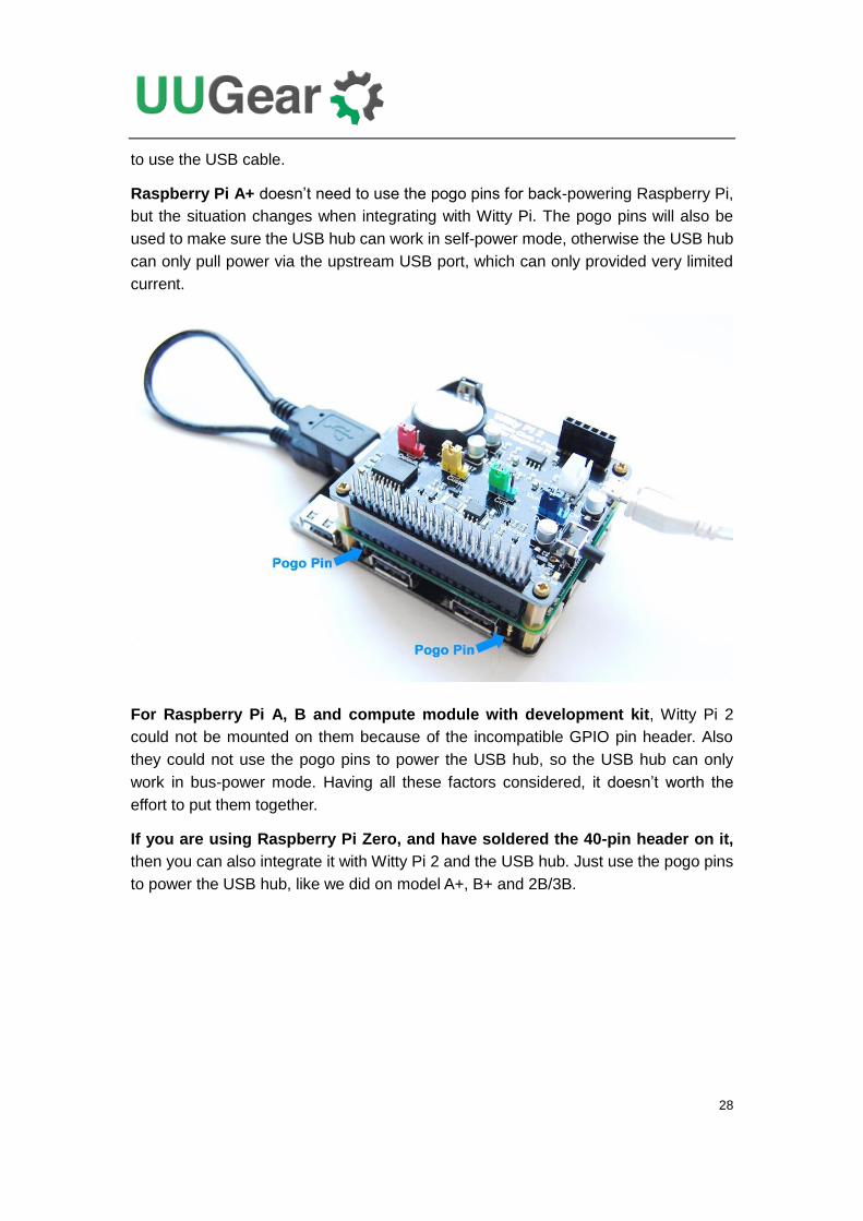
Raspberry Pi A+ doesn’t need to use the pogo pins for back-powering Raspberry Pi,
but the situation changes when integrating with Witty Pi. The pogo pins will also be
used to make sure the USB hub can work in self-power mode, otherwise the USB hub
can only pull power via the upstream USB port, which can only provided very limited
current.
For Raspberry Pi A, B and compute module with development kit, Witty Pi 2
could not be mounted on them because of the incompatible GPIO pin header. Also
they could not use the pogo pins to power the USB hub, so the USB hub can only
work in bus-power mode. Having all these factors considered, it doesn’t worth the
effort to put them together.
If you are using Raspberry Pi Zero, and have soldered the 40-pin header on it,
then you can also integrate it with Witty Pi 2 and the USB hub. Just use the pogo pins
to power the USB hub, like we did on model A+, B+ and 2B/3B.
29
30
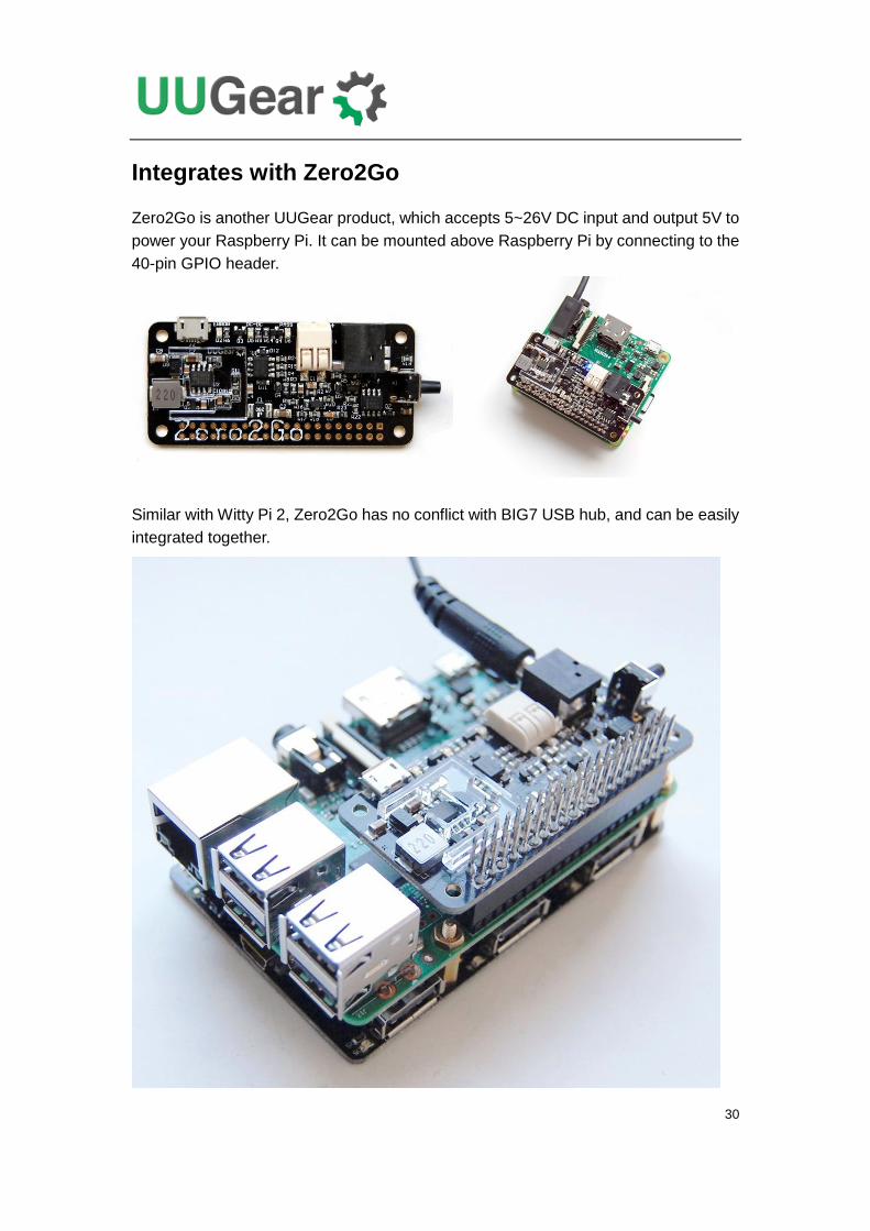
Integrates with Zero2Go
Zero2Go is another UUGear product, which accepts 5~26V DC input and output 5V to
power your Raspberry Pi. It can be mounted above Raspberry Pi by connecting to the
40-pin GPIO header.
Similar with Witty Pi 2, Zero2Go has no conflict with BIG7 USB hub, and can be easily
integrated together.
Top Related