


Languages
Pages
Legal

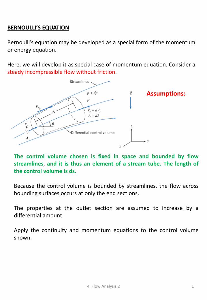
BERNOULLI’S EQUATION Bernoulli’s equation may be developed as a special form of the momentum or energy equation. Here, we will develop it as special case of momentum equation. Consider a steady incompressible flow without friction.
The control volume chosen is fixed in space and bounded by flow streamlines, and it is thus an element of a stream tube. The length of the control volume is ds. Because the control volume is bounded by streamlines, the flow across bounding surfaces occurs at only the end sections. The properties at the outlet section are assumed to increase by a differential amount. Apply the continuity and momentum equations to the control volume shown.
Assumptions:
4 Flow Analysis 2 1
2
Continuity Equation
0
CSC
AdVdt
flowSteadydt
C
0
0 dAAdVVAV sss
s-component of the momentum equation
volumecontrol theof surface
stream bounding on theacting force pressure
2dA
dppdAAdpppAF
sS
Note: No friction, Rs = 0
The body force component in s-direction is,
dsdA
AgdgF ssB
2sin
dzds sinNote:
The momentum flux will be
continuityfrom
ssssss
CS
s dAAdVVdVVAVVAdVu
dAAdVVAV sss …………………. (1)
CS
s
C
ssBsS AdVudut
FF
…………….. (2)
dpdAAdpFsS
2
1 ……………….. (3)
The surface force component in s-direction is,
dzdA
AgFsB
2 ………… (4)
4 Flow Analysis 2
3
From continuity,
dAAdVVAV sss
Hence,
sssssss
CS
s AdVVAVdVVAVVAdVu …………….. (5)
Substituting Eq. (3), (4), and (5) into (2)
ss AdVVgdAdzgAdzdpdAAdp
00
2
1
2
1
Dividing by A and noting that products of differentials are negligible compared to the remaining terms, we obtain
ssdVVgdzdp
2
2sV
dgdzdp
02
2
gdz
Vd
dp s
For incompressible flow ( = constant), this equation can be integrated to obtain
tConsgzVp s tan2
2
BERNOULLI EQUATION
This equation subject to restrictions: 1. Steady flow 2. No friction 3. Incompressible flow 4. Flow along a streamline
4 Flow Analysis 2
4
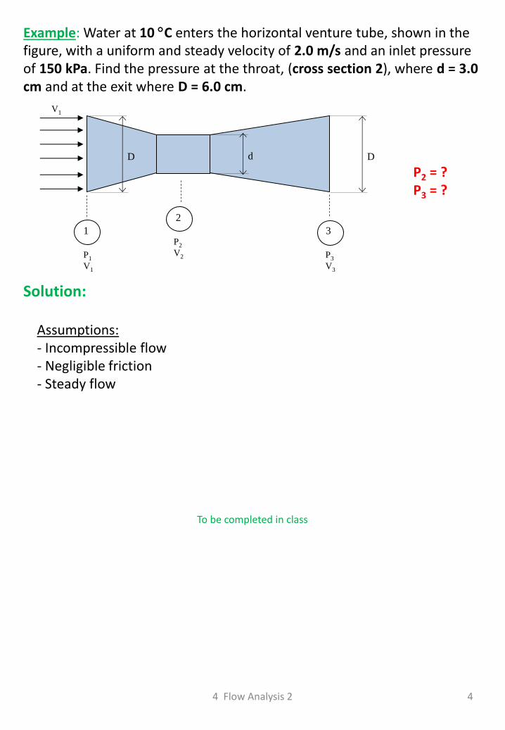
Example: Water at 10 C enters the horizontal venture tube, shown in the figure, with a uniform and steady velocity of 2.0 m/s and an inlet pressure of 150 kPa. Find the pressure at the throat, (cross section 2), where d = 3.0 cm and at the exit where D = 6.0 cm.
V1
P1
V1
1 P2
V2
2
P3
V3
3
d D D
P2 = ? P3 = ?
Solution:
Assumptions: - Incompressible flow - Negligible friction - Steady flow
4 Flow Analysis 2
To be completed in class

4 Flow Analysis 2 5
6
Example: A city has a fire truck whose pump and hose can deliver 60 lt/sec with nozzle velocity of 36 m/sec. The tallest building in the city is 30 m high. The firefighters hold the nozzle at an angle of 75 from the ground. Find the minimum distance the firefighters must stand from the building to put out a fire on the roof without the aid of a ladder. The firefighters hold the hose 1 m above the ground. Assume that the water velocity is not reduced by air resistance.
4 Flow Analysis 2
To be completed in class

4 Flow Analysis 2 7
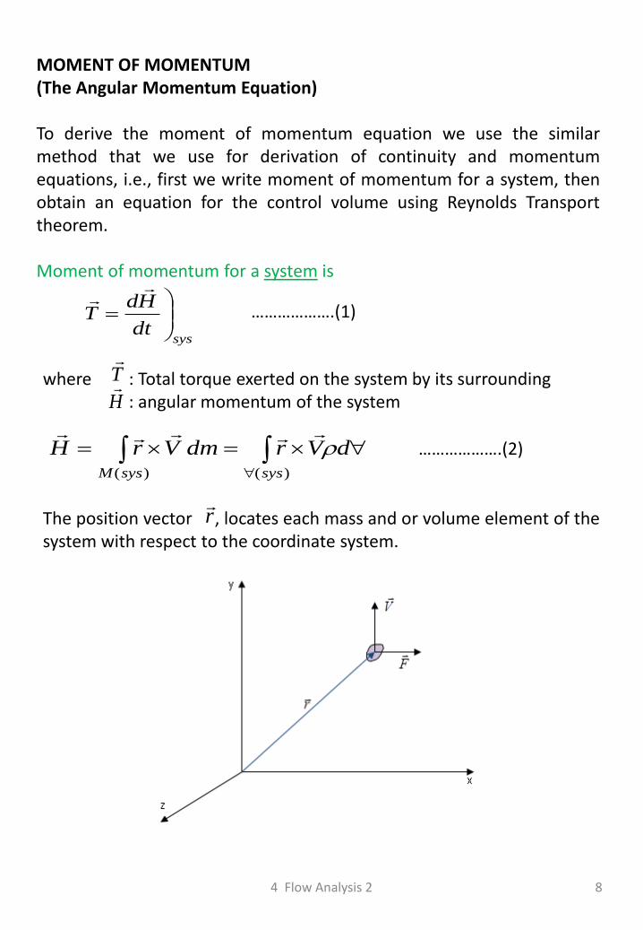
MOMENT OF MOMENTUM (The Angular Momentum Equation) To derive the moment of momentum equation we use the similar method that we use for derivation of continuity and momentum equations, i.e., first we write moment of momentum for a system, then obtain an equation for the control volume using Reynolds Transport theorem. Moment of momentum for a system is
sysdt
HdT
……………….(1)
T
Hwhere : Total torque exerted on the system by its surrounding
: angular momentum of the system
)()( syssysM
dVrdmVrH
……………….(2)
r
The position vector , locates each mass and or volume element of the system with respect to the coordinate system.
4 Flow Analysis 2 8
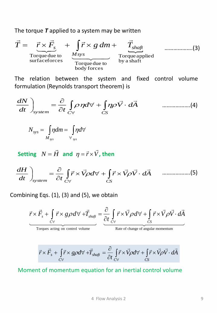
The torque T applied to a system may be written
shaft aby applied Torque
forcesbody todue Torque
forces surface todue Torque
shaft
sysM
s TdmgrFrT
……………….(3)
The relation between the system and fixed control volume formulation (Reynolds transport theorem) is
CSCsystem
AdVdtdt
dN ……………….(4)
syssys
ddmN
M
sys
HN
Vr
Setting and , then
CSCsystem
AdVVrdVrtdt
dH ……………….(5)
Combining Eqs. (1), (3) and (5), we obtain
Torques acting on control volume Rate of change of angular momentum
s shaft
C C CS
r F r g d T r V d r V V dAt
CSC
shaft
C
s AdVVrdVrt
TdgrFr
Moment of momentum equation for an inertial control volume
4 Flow Analysis 2 9
Example: Consider the pipe mounted on a wall shown in figure. The pipe inside diameter is 20 cm, and both pipe bends are 90. Water enters the pipe at the base and exits at the open end with a speed of 10 m/s. Calculate the torsional moment and the bending moment at the base of the pipe. Neglect the weight of water and pipe.
4 Flow Analysis 2 10
To be completed in class

4 Flow Analysis 2 11
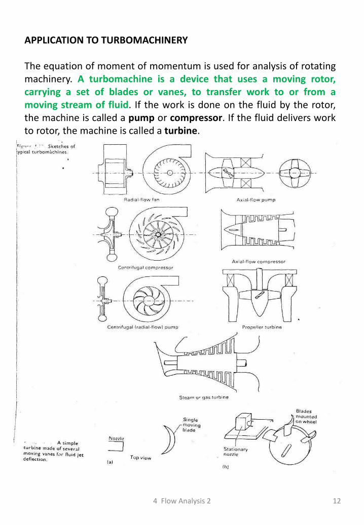
APPLICATION TO TURBOMACHINERY The equation of moment of momentum is used for analysis of rotating machinery. A turbomachine is a device that uses a moving rotor, carrying a set of blades or vanes, to transfer work to or from a moving stream of fluid. If the work is done on the fluid by the rotor, the machine is called a pump or compressor. If the fluid delivers work to rotor, the machine is called a turbine.
4 Flow Analysis 2 12
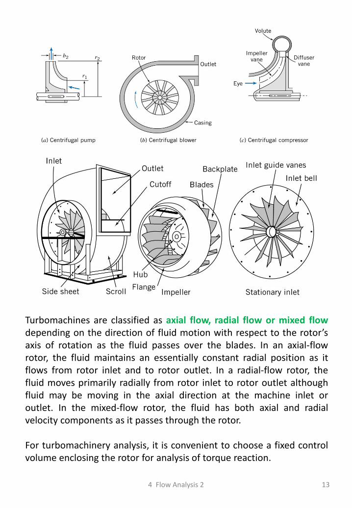
Turbomachines are classified as axial flow, radial flow or mixed flow depending on the direction of fluid motion with respect to the rotor’s axis of rotation as the fluid passes over the blades. In an axial-flow rotor, the fluid maintains an essentially constant radial position as it flows from rotor inlet and to rotor outlet. In a radial-flow rotor, the fluid moves primarily radially from rotor inlet to rotor outlet although fluid may be moving in the axial direction at the machine inlet or outlet. In the mixed-flow rotor, the fluid has both axial and radial velocity components as it passes through the rotor. For turbomachinery analysis, it is convenient to choose a fixed control volume enclosing the rotor for analysis of torque reaction.
4 Flow Analysis 2 13
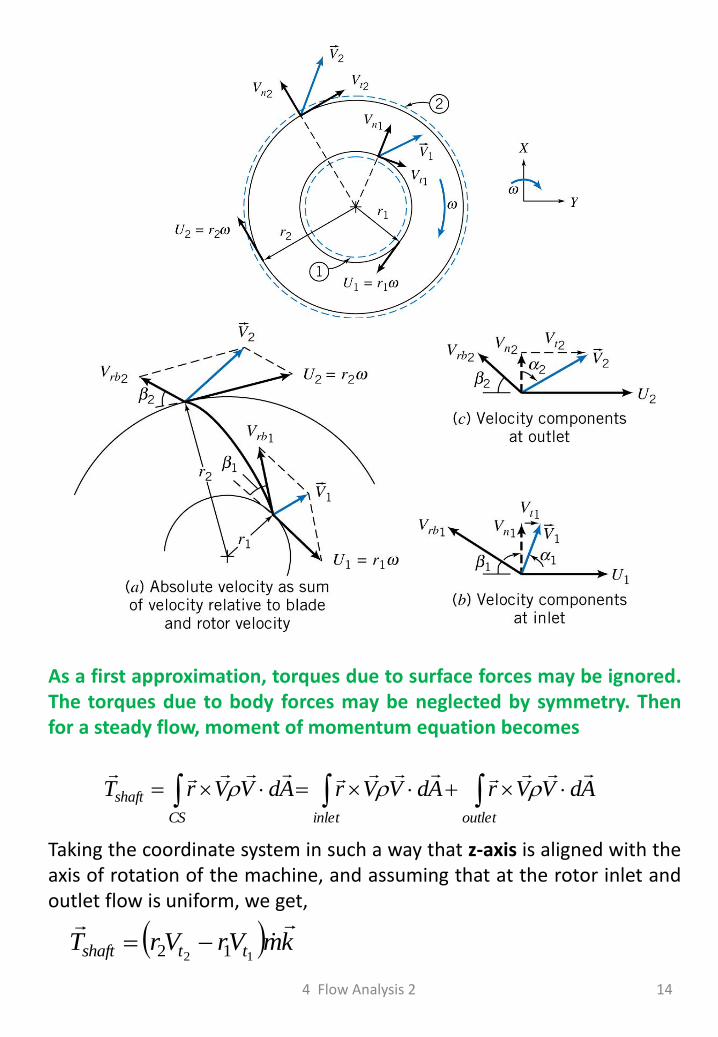
As a first approximation, torques due to surface forces may be ignored. The torques due to body forces may be neglected by symmetry. Then for a steady flow, moment of momentum equation becomes
outletinletCS
shaft AdVVrAdVVrAdVVrT
Taking the coordinate system in such a way that z-axis is aligned with the axis of rotation of the machine, and assuming that at the rotor inlet and outlet flow is uniform, we get,
kmVrVrT ttshaft
12 12
4 Flow Analysis 2 14
or in scalar form
mVrVrT ttshaft 12 12 EULER TURBINE EQUATION
1tV
2tVwhere and are tangential components of the absolute fluid
velocity crossing the control surface at inlet and outlet, respectively. The rate of work done on a turbomachinery rotor is
mVUVU
mVrVr
TkTkTW
tt
tt
shaftshaftshaftin
12
12
12
12
Ur NOTE: tangential velocity of the rotor.
gmDividing both sides by , we obtain head added to the flow.
12 12
1tt
in VUVUggm
Wh
[m]
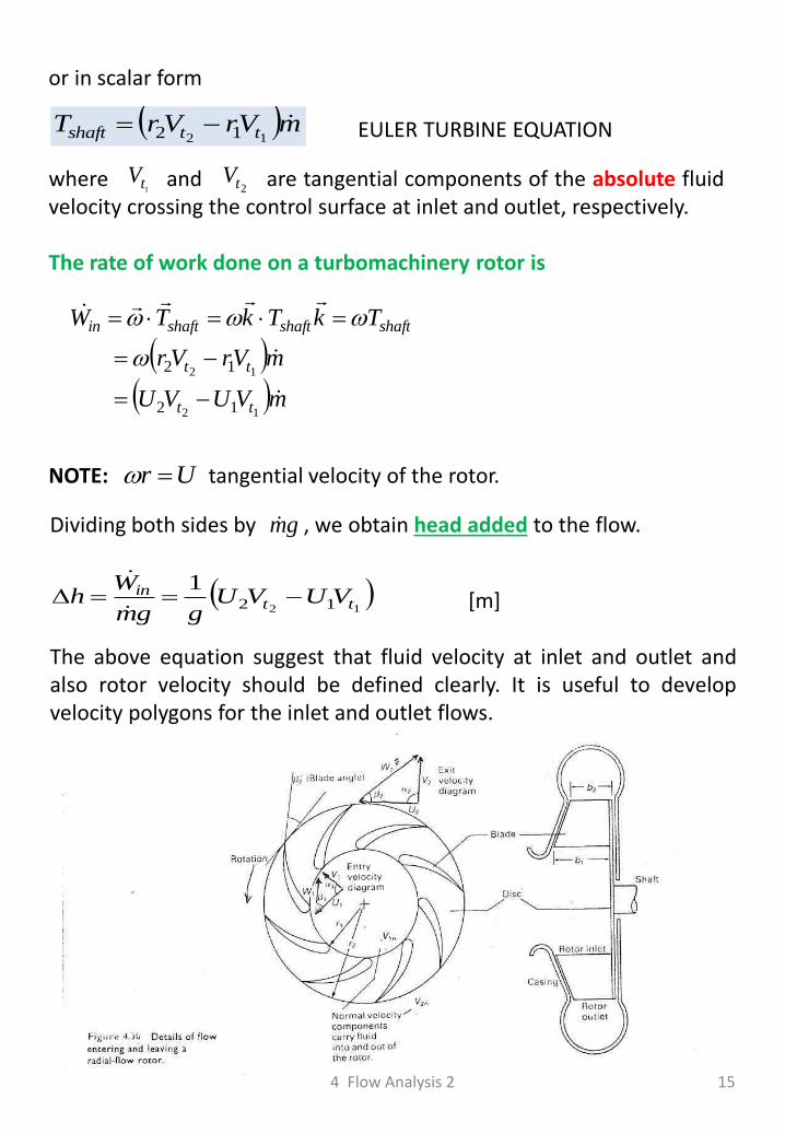
The above equation suggest that fluid velocity at inlet and outlet and also rotor velocity should be defined clearly. It is useful to develop velocity polygons for the inlet and outlet flows.
4 Flow Analysis 2 15
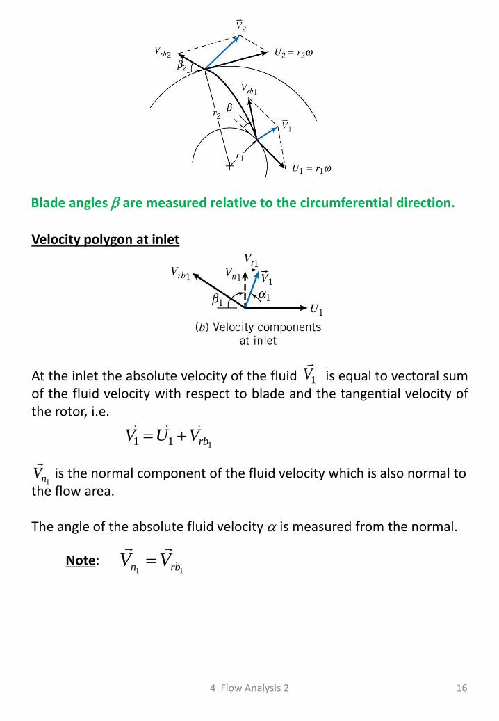
Blade angles are measured relative to the circumferential direction.
Velocity polygon at inlet
1V
At the inlet the absolute velocity of the fluid is equal to vectoral sum of the fluid velocity with respect to blade and the tangential velocity of the rotor, i.e.
111 rbVUV
1nV
is the normal component of the fluid velocity which is also normal to the flow area. The angle of the absolute fluid velocity is measured from the normal.
Note: 11 rbn VV
4 Flow Analysis 2 16
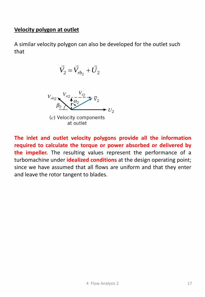
The inlet and outlet velocity polygons provide all the information required to calculate the torque or power absorbed or delivered by the impeller. The resulting values represent the performance of a turbomachine under idealized conditions at the design operating point; since we have assumed that all flows are uniform and that they enter and leave the rotor tangent to blades.
Velocity polygon at outlet A similar velocity polygon can also be developed for the outlet such that
22 2UVV rb
4 Flow Analysis 2 17
18
Example: The axial-flow hydraulic turbine has a water flow rate of 75 m3/s, an outer radius R = 5.0 m, and a blade height h = 0.5 m. Assume uniform properties and velocities over both the inlet and the outlet. The water temperature is 20 C, and the turbine rotates at 60 rpm. The relative velocities Vr1 and Vr2 make angles of 30 and 10, respectively, with the normal to the flow area. Find the output torque and power developed by the turbine.
4 Flow Analysis 2
To be completed in class

4 Flow Analysis 2 19
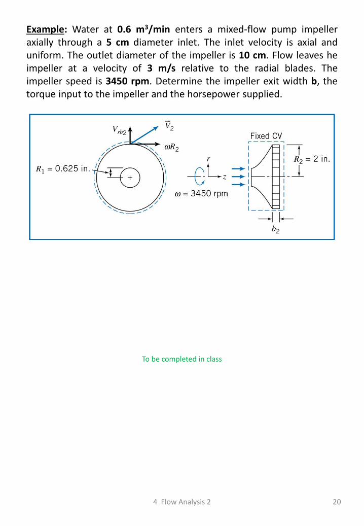
Example: Water at 0.6 m3/min enters a mixed-flow pump impeller axially through a 5 cm diameter inlet. The inlet velocity is axial and uniform. The outlet diameter of the impeller is 10 cm. Flow leaves he impeller at a velocity of 3 m/s relative to the radial blades. The impeller speed is 3450 rpm. Determine the impeller exit width b, the torque input to the impeller and the horsepower supplied.
4 Flow Analysis 2 20
To be completed in class

4 Flow Analysis 2 21
Top Related