


Languages
Pages
Legal


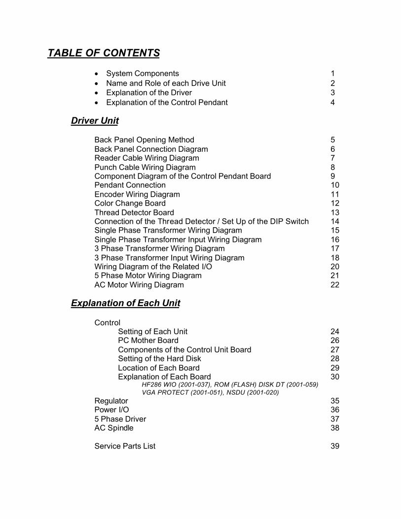
TABLE OF CONTENTS
• System Components 1
• Name and Role of each Drive Unit 2
• Explanation of the Driver 3
• Explanation of the Control Pendant 4
Driver Unit
Back Panel Opening Method 5
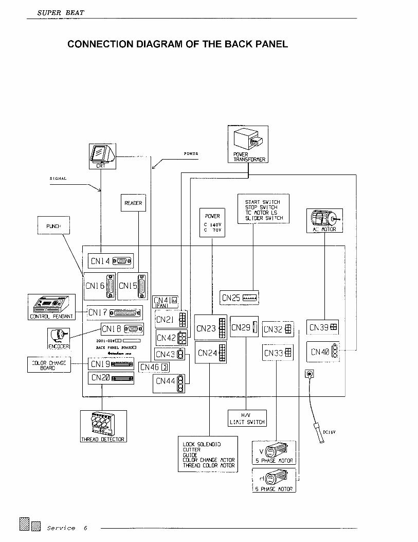
Back Panel Connection Diagram 6Reader Cable Wiring Diagram 7
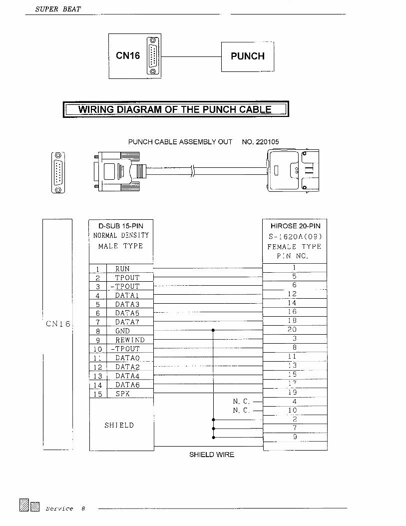
Punch Cable Wiring Diagram 8Component Diagram of the Control Pendant Board 9Pendant Connection 10
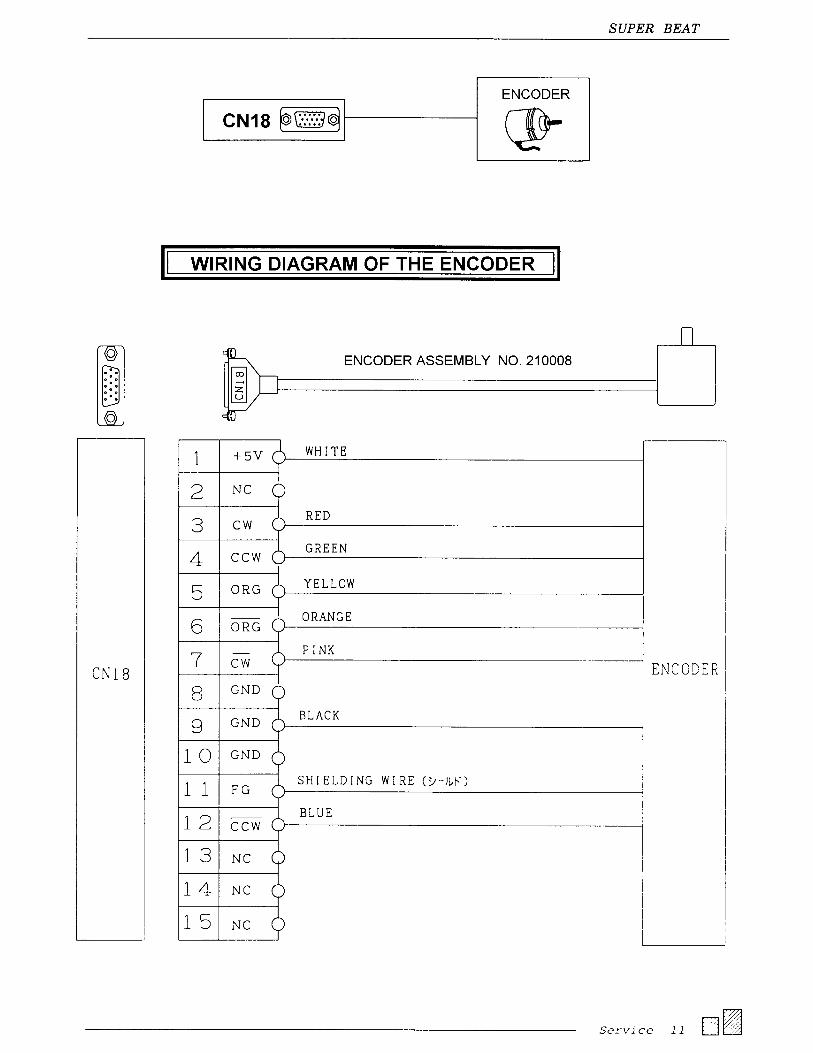
Encoder Wiring Diagram 11Color Change Board 12
Thread Detector Board 13Connection of the Thread Detector / Set Up of the DIP Switch 14Single Phase Transformer Wiring Diagram 15
Single Phase Transformer Input Wiring Diagram 163 Phase Transformer Wiring Diagram 17
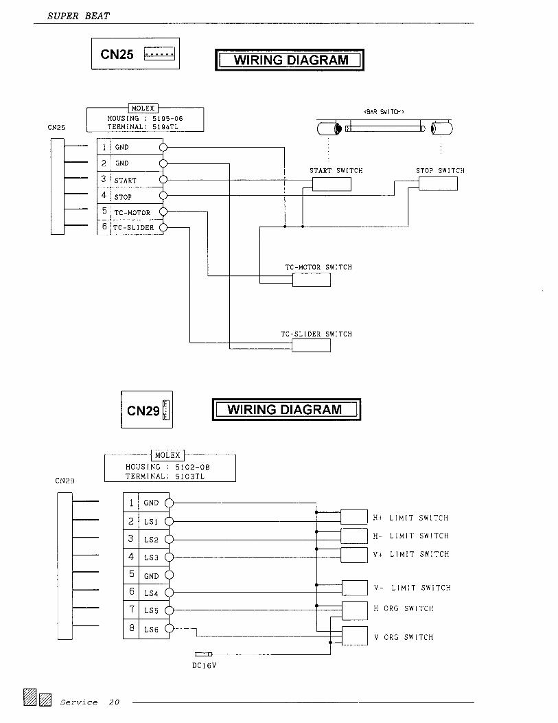
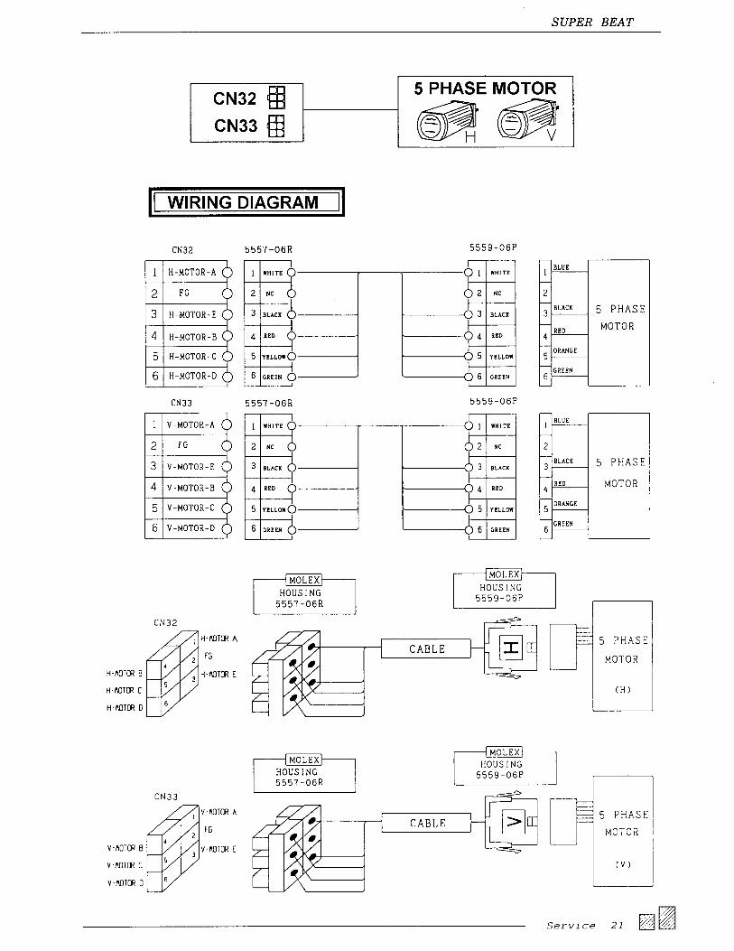
3 Phase Transformer Input Wiring Diagram 18Wiring Diagram of the Related I/O 205 Phase Motor Wiring Diagram 21
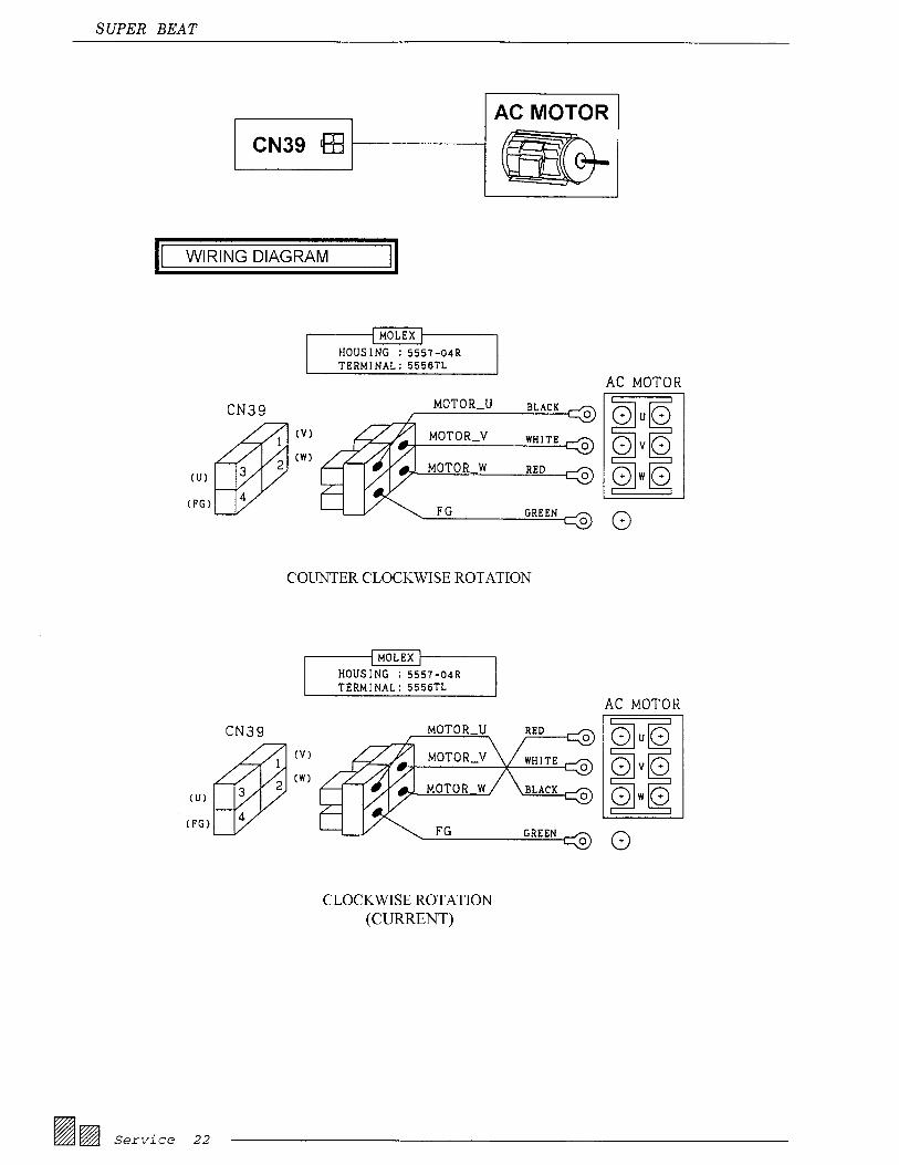
AC Motor Wiring Diagram 22
Explanation of Each Unit
ControlSetting of Each Unit 24PC Mother Board 26
Components of the Control Unit Board 27Setting of the Hard Disk 28
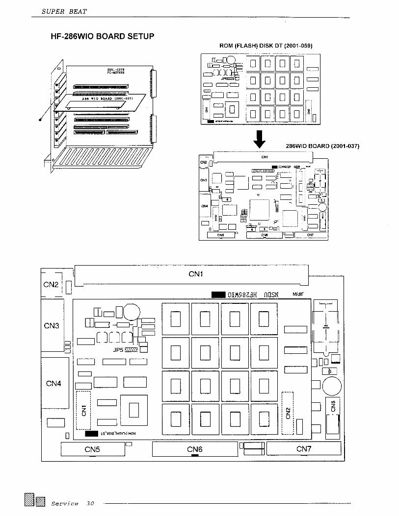
Location of Each Board 29Explanation of Each Board 30
HF286 WIO (2001-037), ROM (FLASH) DISK DT (2001-059)
VGA PROTECT (2001-051), NSDU (2001-020)
Regulator 35Power I/O 36
5 Phase Driver 37AC Spindle 38
Service Parts List 39


Service 39
SUPER BEAT SERVICE PARTS LIST
DESCRIPTION JAPAN PART NO. BA PART NO.
CONTROL UNIT ASSY. (286 PROCESSOR) W/OUT HD 260239 EBN01690
286 PROCESSOR
ROM (Flash) DISK DT ASSY. 1.M TYPE 2001-036/ 074 EBN02010
VGA/PROTECT BOARD ASSY. 2001-051 EBN01980
NSDU HF286WIO ASSY. 2001-037 EBN01990
CONTROL UNIT ASSY. (486 PROCESSOR) W/OUT HD EBN02187
486 PROCESSOR
ROM (FLASH) & VGA BOARD 2001-0934 EBN02182
PROTECT BOARD 2001-051A-ADP-077 EBN02183
HF486 SLF BOARD 2001-063-ADP-078 EBN02181
REGULATOR UNIT ASSY. BEAT900 260212 EBN01700
POWER I/O UNIT ASSY. BEAT900 260213 EBN01710
5 PHASE DRIVER UNIT ASSY. BEAT900 260214 EBN01720
AC SPINDLE UNIT ASSY. BEAT900 260216 EBN01730
CONTROL PENDANT UNIT ASSY. BEAT900 260221 EAN058A3
BACK BOARD ASSY. 260217 EBN01750
ENCODER ASSY. 210008 EBN01670
THREAD DETECTOR BOARD & CABLE ASSY. (YS) 260229 EBN01660
NSDU COLOR CHANGE BOARD (YS) 2001-018A EBN01650
HEAD BOARD (YN) 2001-097 EBN02184
COLOR CHANGE BOARD (YN) 2001-096A EBN02185
UTSM DETECTOR BOARD (YN/ZN) 2001-0956 EBN02186
NEEDLE POSITIONER (ZN) EBN02193
HEAD SWITCH BOARD (ZN) 2001-118 EBN02191
14” COLOR VGA MONITOR BEAT900 EAN058A5
MOUSE (SERIAL) BEAT900 EBN01780
KEYBOARD (81 KEY) BEAT900 260222 EBN01790
2.5” HARD DISK DRIVE UNIT (130M Bytes) 320402 FA904108
2.5” HARD DISK DRIVE UNIT (20M Bytes) 320401 EBN01800
PULSE MOTOR ASSY. (6 HD) EM5913H-NA-A1 EBN01810
PULSE MOTOR ASSY. (2 HD) EM599H-NA-A1 EBN01820
READER INPUT CABLE ASSY. (L=3.0m) 220104 H1628
PUNCH OUT CABLE ASSY. (L=3.0m) 220105 H1629
PENDANT CONNECTION CABLE ASSY. (L=3.5m) 240136 EBN01850
COLOR CHANGE CABLE ASSY. (L=4.1m) KHJ999-0280-A0 EBN01860
TRANSFORMER CABLE ASSY. 250202
VGA SIGNAL EXTENTION CABLE ASSY. (L=2.2) 270269
CRT POWER EXTENTION CABLE ASSY. (L=1.8m) 260206
H-PULSE MOTOR EXTENTION CABLE ASSY. 220107
V-PULSE MOTOR EXTENTION CABLE ASSY. (L=2.6m) 220108
TERMINAL KEYBOARD ASSY. ATTACHED VR. CONTROL 260225 EBN01940
TERMIANL BOARD ASSY. 2001-025 EBN01950
PC MOTHER BOARD ASSY. 2001-027 EBN01960
NSDU BOARD ASSY. 2001-020 EBN01970
2.5” HD CONNECTION BOARD ASSY. 2001-038 EBN02020
3.5” FDD (720KB/1.44MB) YD-702B-6037B-#0221 EBN02090
EMERGENCY SWITCH ASSY. 220020
POWER SWITCH ASSY. 220017
FAN MOTOR ASSY. 220109
1P TRANSFORMER 2 HD 32039714 EAN058A2
1P TRANSFORMER 6 HD 32039814 EAN061A2
3P TRANSFORMER 8 HD 32039914 EAN063A2
3P TRANSFORMER 12 HD ATTACHED COVER 32040014

SUPER BEAT SERVICE PARTS LISTAdditional parts
Description Part Number
Driver box Fan A9065016
Fans for AC Spindle and Pulse Motor Units FA911511
BEAT 900 HD Assembly ZA200183
Battery for CMOS FY000035

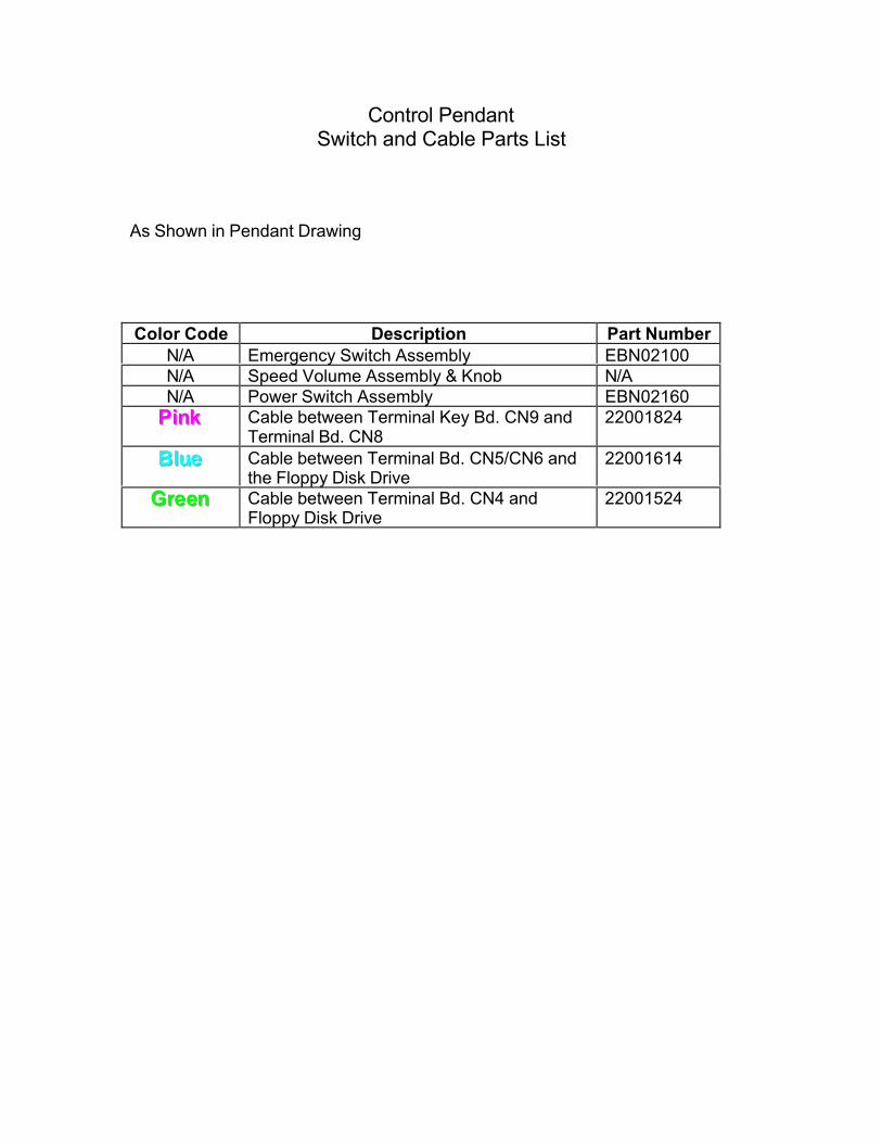
Control PendantSwitch and Cable Parts List
As Shown in Pendant Drawing
Color Code Description Part Number
N/A Emergency Switch Assembly EBN02100
N/A Speed Volume Assembly & Knob N/A
N/A Power Switch Assembly EBN02160
PPPiiinnnkkk Cable between Terminal Key Bd. CN9 andTerminal Bd. CN8
22001824
BBBllluuueee Cable between Terminal Bd. CN5/CN6 andthe Floppy Disk Drive
22001614
GGGrrreeeeeennn Cable between Terminal Bd. CN4 andFloppy Disk Drive
22001524


Control UnitCable Parts List
As Shown in Control Unit Drawing
Color Code Description Part Number
PPPiiinnnkkk Cable between 286/486 WIO Bd. CN5 andMother Bd. CN12
22011224
BBBllluuueee Cable between 286/486 WIO Bd. CN6 and
Mother Bd. CN13
24013924
VVViiiooollleeettt Cable between 286/486 WIO Bd. CN8 andMother Bd. CN14
22011034
GGGrrreeeeeennn Cable between 286/486 WIO Bd. CN7 and
Hard Disk CN2
22011324
YYYeeellllllooowww Cable between Mother Bd. CN15 and VGAProtect Bd. CN3
26020724


APPENDIX – TABLE OF CONTENTS
1. DOS Prompt 1
2. Installation 23. Parameter File 4


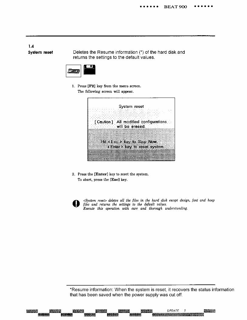

System Reset Executing a system reset restores all machine settings to factory default settings. It also refreshes the Flash Roms on the WIO/CPU, NSDU, Power I/O, 5 Phase Driver, and the AC Spindle.
1. Power down machine.
2. Power machine ON, as it starts to boot up start tapping the Scroll Lock key until the scroll lock light is lit.
3. The machine will boot up into the Shell menu with the [F6]
option Update System.
4. Press [F6].
5. Press [F2] for System Reset.
6. Press Enter key to reset system, or the Esc key to cancel.
7. Press [F2] for Beat system
8. Machine will then resume booting up.

Boot Sequence
During the boot process and during system resets, communication is established with the Flash Rom on each board in the Drive box. If any one of these boards is defective, the system will lock up at that point during the boot cycle. When the system loads properly you will see “Now loading” at the bottom of the screen and the two-letter code that follows (the board that would be loading). When system reset is complete there will be a long beep.
CODE BOARD
WO WIO or CPU V-E NSDU
R-E Power I/O
P-E 5 Phase Driver
S-E AC Spindle

System Update The following instructions explain how to update the system software on the BEAT 900 to a newer version, using Floppy disks. Note: If you’re making repairs or changing electronic boards in the machine, you must use the DOS procedure for installing this software. Please call your Barudan technician for instructions on this procedure
1. Power down machine.
2. Power machine ON, as it starts to boot up start tapping the Scroll Lock key until the scroll lock light is lit.
3. The machine will boot up into the Shell menu with the [F6] option Update System.
4. Press [F6].
5. Press [F1] for System Update.
6. Follow the prompts on the screen:
a. Insert Disk 1 in Drive A
b. Insert Disk 2 in Drive B
c. Press the Enter key to start the update when you are ready
7. After step 6 is done, the screen will prompt for Disks 3 & 4:
a. Insert Disk 3 into Drive A
b. Insert Disk 4 into Drive B
c. Press the Enter key to finish the update when you are ready
8. Screen will Prompt when the “Update is Complete”. Power off the machine when finished. Wait 5 seconds, and Power back ON. Machine should be ready to go.


TECHNICAL BULLETIN
BT-028
DATE: May 30, 1995
SOFTWARE VERSION: BEAT 900 2.02EYS Rev 10
BEAT 900 2.02EYN Rev 10
MACHINE/PERIPHERAL: BEAT 900 Series
PART NO: EBN02181 2001-063-ADP-078 HF486 SLF Board
EBN02182 2001-0934 Flash & VGA BoardEBN02183 2001-051A-ADP-077 Protect BoardEBN02184 2001-097 Head Board YNEBN02185 2001-096A Color Change Board YNEBN02186* 2001-0956 UTSM Detect Board
*(UTSM only)
ISSUE/PROBLEM:
As of machine S/N 951386F, all BEAT 900 machines will have YN sewing headsand contain a 486 processor board. The 486 processor requires new softwareand has a different BIOS set-up procedure. The current software for the YN is2.02EYN Rev 10.
This Tech Bulletin contains instructions for the following:1. Setting up the new BIOS, specifically, changing the parameters for
the hard drive type.2. Booting from a floppy disk.
SUMMARY:
The YN machine has five new boards which were not present in YS models.There is now a total of six boards, if the optional UTSM board is included.
The Head Board and Color Change Board were changed to permit the detectionof nine needles. The CPU Board, Flash and Protect boards were also modifiedto add the faster 486 processor and an enhanced video driver.
YS 486 UpgradeYS models currently in the field can be upgraded to the 486 processor by addingjust the HF486SLF Board (EBN02181 2001-063-ADP-078), and Softwareversion 2.02EYS Rev 10.Please note that you must use the customer's old Flash Memory Board andVideo/Protect Board. The new Flash Memory (EBN02182) contains a videodriver that will conflict with the video driver on the old Video/Protect Board.

!"# $%&&!'() $ *+,-
,
BEAT 900 YN SETUP
A. BIOS SetupThe CPU Board has changed from HF286WIO to HF486SLC(2001-063-ADP-078). Follow the steps below to set up the CPU board.
1. Turn off the controller.2. Turn the power back on.
3. Immediately after the routine memory check, press F2 (see page A,attached).The Extended BIOS Menu (see page B, attached) will be displayed.
4. The Setup option should already be selected. Press [Enter] to display theBIOS Setup screen (see page C, attached).
5. Use the arrow keys to move the pointer to the Fixed Disk 0 option (seepage D, attached).
6. Use the F5 or F6 key to select the hard disk type (41 for 130M; 6 for20M).
If necessary, correct the time and date.
7. Press [Esc] when you are done. The Notice warning you that the newconfiguration has not been saved is displayed (see page E, attached).
8. The Yes option should already be highlighted. Press [Enter] to save thenew BIOS setup. The Extended BIOS Menu will be displayed.
9. Press [Esc] to exit the menu.
B. Booting from FloppyIf you are not able to boot the system from ROM (i.e., HD format), follow the
stepsbelow to boot from floppy.
1. Turn off the controller.2. Turn the power back on.
3. Immediately after the routine memory check, press F2 (see page A,attached).The Extended BIOS Menu (See page B, attached) will be displayed.
4. Use the arrow keys to select Extended BIOS Features.
5. Press [Enter] to display the Extended BIOS Features screen (seepage H, attached).
6. Use the arrow keys to move the pointer to the Quick Boot option.
7. Press F5 to select No for this option.
8. Press [Esc] when you are done, to exit the screen.
9. Locate SW 1 (4 pin dip) on the FLASH & SVGA (2001-093A) board,
and turn the #1 dipswitch ON.10. Turn off the computer.11. Turn the power back on.
The screen will show two options, booting from ROM or disk (seepage J, attached).
12. Insert Floppy Update Disk #1 in the A drive.
13. Press F2 to boot from the floppy.14. Return the dipswitch to the normal setting.
Normal setting for dipswitch: 1-off, 2-off, 3-on, 4-onQuick Boot: yes.


CCOONNTTRROOLL UUNNIITT TTEESSTTIINNGG In Cleveland using 902 YS Test machine
February 10, 2003
TO PREPARE A CONTROL UNIT FOR TESTING:
! Click on "Drive" and select "Exit to Shell" ! Hold down the Alt key and press F1 to shell out to DOS. ! Insert Disk 1 into Drive A. ! Type "A:" and press ENTER. ! Type "install" and press ENTER ! Swap disks and press ENTER until all 4 disks have been read. ! Remove last disk. ! Type "902AM700" and press ENTER. ! When DOS prompt appears, power down and power back up. ! When through booting, press the Frame Org. button. ! Click on Drive, then Open ! Double click on Earl. ! Click on OK and OK again. ! Verify hoop file is "Hoop02e0" ! Press the red Drive button, use the H and V buttons to position to clean fabric,
and slide the start bar to the left. TO IDENTIFY THE DIFFERENCES BETWEEN YN AND YS CONTROL UNITS:
! YS Units EBN01690: ! The middle board is filled with circuitry. ! A ribbon cable is plugged into the far end of the middle board.
! YN Units EBN02187: ! Almost no circuitry on the middle board. ! No cables plugged into the middle board.
MACHINE STOPS DURING BOOT, DISPLAYS "F1 to..., F2 to...."
! On YS Control Units EBN01690: ! Move Jumper on Flash Disk Board (Piggy back board) to pins 1 & 2 ! Jumpers are near top of board, near the middle. ! Removing middle ribbon cable will make this job easier. ! There is no need to remove the board from the Control Unit.
! On YN Control Units EBN02187: ! Adjust DIP Switch settings on Flash Disk Board ! Switches are near bottom of board, about 2” from left end ! Switches 1, 2, 3, and 4 should be OFF, OFF, ON, and ON
1

2
MISCELLANEOUS NOTES
! Always shell out to NASH or DOS before powering down. ! Always kill power on back of keyboard first, then kill circuit breaker. ! From the NASH menu, Alt. F1 will exit to DOS. ! From DOS, type in “exit” and enter to exit to NASH menu. ! Test all YN Control Units with type 41 (130 meg) hard drive. ! Test all YS Control Units with type 6 (20 meg) hard drive, or use type 41 and
then reset CMOS settings back to type 6 before shipping. ! Read Write Errors indicate bad D: Drive (Flash memory) ! When no shipping boxes are available, use a 15x12x10 box (Uline S-4153) ! YN Control Unit: Hold down the [F2] key while booting to access BIOS settings ! YS Control Unit: Hold down [Ctrl] [Alt] and press [S] while booting to access
BIOS settings ! Scroll Lock during booting will abort and leave you in the NASH menu ! Control Units received from Japan will have the wrong software installed. This
will sometimes be the reason for not booting properly or hanging during boot. ! To update the system, from the NASH screen, press F6 and then F2.
IMPORTANT BARUDAN CONTROL UNIT PART NUMBERS
PART
NUMBER DESCRIPTION
EBN01690 Control Unit (260-239) YS (CPU = 286) EBN01960 Mother Board, 2001-027 EBN01970 NSDU Board, 2001-020 EBN01990 HF286 WIO Board, 2001-037 EBN02010 FLASH ROM Board, 2001-074 8M (For 286 boards) EBN02181 HF486 Board, 2001-063 EBN02182 FLASH ROM $ SVGA Board, 2001-093A (For 386/486 boards) EBN02187 Control Unit (900-YN) (CPU = 386 Enhanced)
FY000035 Battery, 3.6 Volt

520 Mb Hard Drive BIOS settings.txt520 Mb Hard Drive BIOS settings (For BEAT-900 machines)
Macpherson programmed a hand full of Hard Drives for the BEAT 900 at 520Mb.
Because of this, it requires special DISK settings in BIOS as written below.
Note: All the large capacity Hard drives produced from Barudan America, have been formatted to 130 Mb, with a Type 41 BIOS Setting. This was done to avoid the problems with special settings and to set a standard HD Type. Type 41 was also recommended because of it's stability with the BEAT 900 system.
520 Mb settings:
For YS Control Units:
Cyl Hd Pre LZ Sec Size Hard Disk 1 *Type 48 or 49 1024 16 0 1024 63 504
* 48 & 49 let you customize these settings
For YN/ZN Control Units:
Fixed Disk 0: [User] CY:1024 HD:16 ST:63 LZ:1024 WP:None
Page 1
Top Related