


Languages
Pages
Legal

Basic Lighting Techniques for
Machine Vision Daryl Martin
Technical Sales & Product Manager Advanced illumination
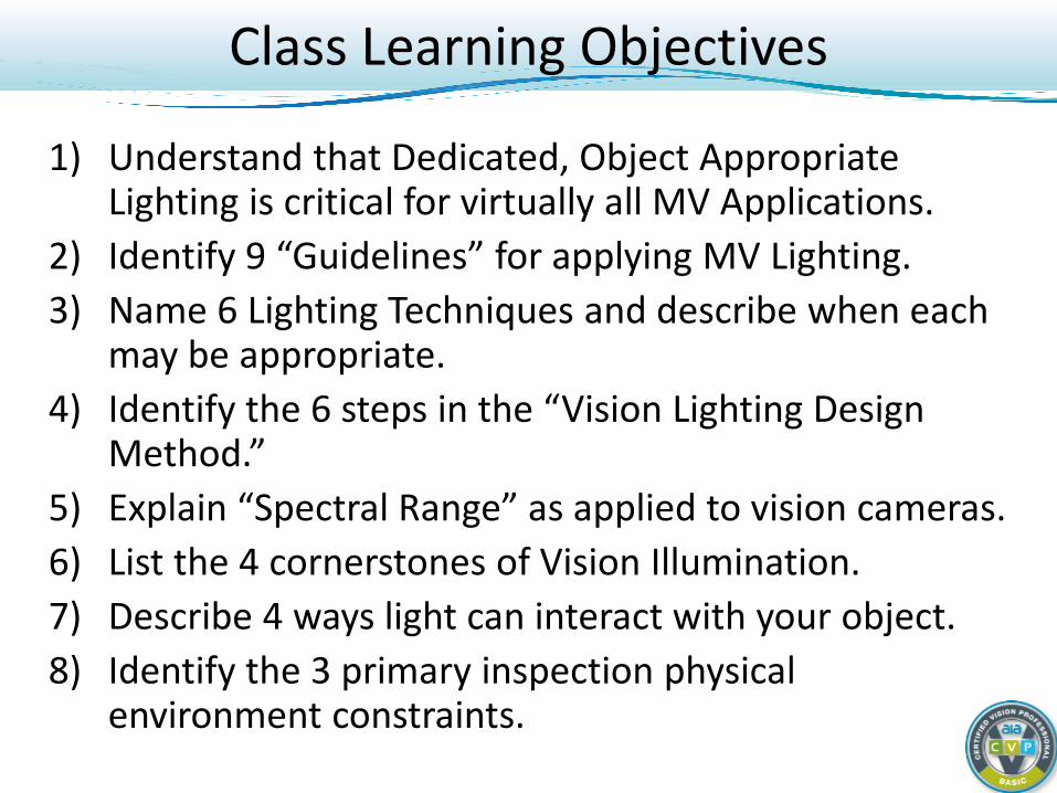
1) Understand that Dedicated, Object Appropriate Lighting is critical for virtually all MV Applications.
2) Identify 9 “Guidelines” for applying MV Lighting. 3) Name 6 Lighting Techniques and describe when each
may be appropriate. 4) Identify the 6 steps in the “Vision Lighting Design
Method.” 5) Explain “Spectral Range” as applied to vision cameras. 6) List the 4 cornerstones of Vision Illumination. 7) Describe 4 ways light can interact with your object. 8) Identify the 3 primary inspection physical
environment constraints.
Class Learning Objectives
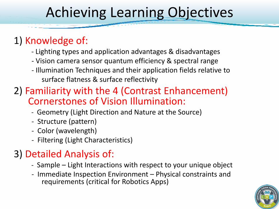
1) Knowledge of: - Lighting types and application advantages & disadvantages - Vision camera sensor quantum efficiency & spectral range - Illumination Techniques and their application fields relative to surface flatness & surface reflectivity 2) Familiarity with the 4 (Contrast Enhancement)
Cornerstones of Vision Illumination: - Geometry (Light Direction and Nature at the Source) - Structure (pattern) - Color (wavelength) - Filtering (Light Characteristics)
3) Detailed Analysis of: - Sample – Light Interactions with respect to your unique object - Immediate Inspection Environment – Physical constraints and
requirements (critical for Robotics Apps)
Achieving Learning Objectives
What we really require is control of the lighting environment! Why?
- Part (Object Feature) inspection & system appropriate lighting
- To the extent possible, standardization of components, techniques, system implementation and operation
- Reproducibility of inspection results
- Robustness to handle sample variations of “all types”
Primary Objective of Vision Lighting
Brief Review of Light as Applied to Machine Vision Compare / Contrast Lighting Sources Review Light / Sample and Light / Camera Interactions Review Basic Lighting Geometry Techniques - Examples
- Directional Bright Field vs. Dark Field - Back Lighting - Preview of Diffuse Lighting Techniques
More Applications Examples Preview of Filtering: Pass and Polarization Preview of Color Lighting Analysis Preview of Near IR and UV Vision Light Lighting for Robotics (time and interest permitting)
Topics
Machine Vision Definitions
Machine Vision is the computer-based characterization of a digital image from an electronic sensor.
A digital image is a 1-D or 2-D array of picture elements (pixels), each having an (X,Y) location and an intensity, typically 0 – 255 gray scales, or 8-bit contrast.
Contrast is the visible intensity difference between dark (near 0) and light (near 255) pixels.
In its most derivative form, then we are characterizing light contrast patterns from an object.
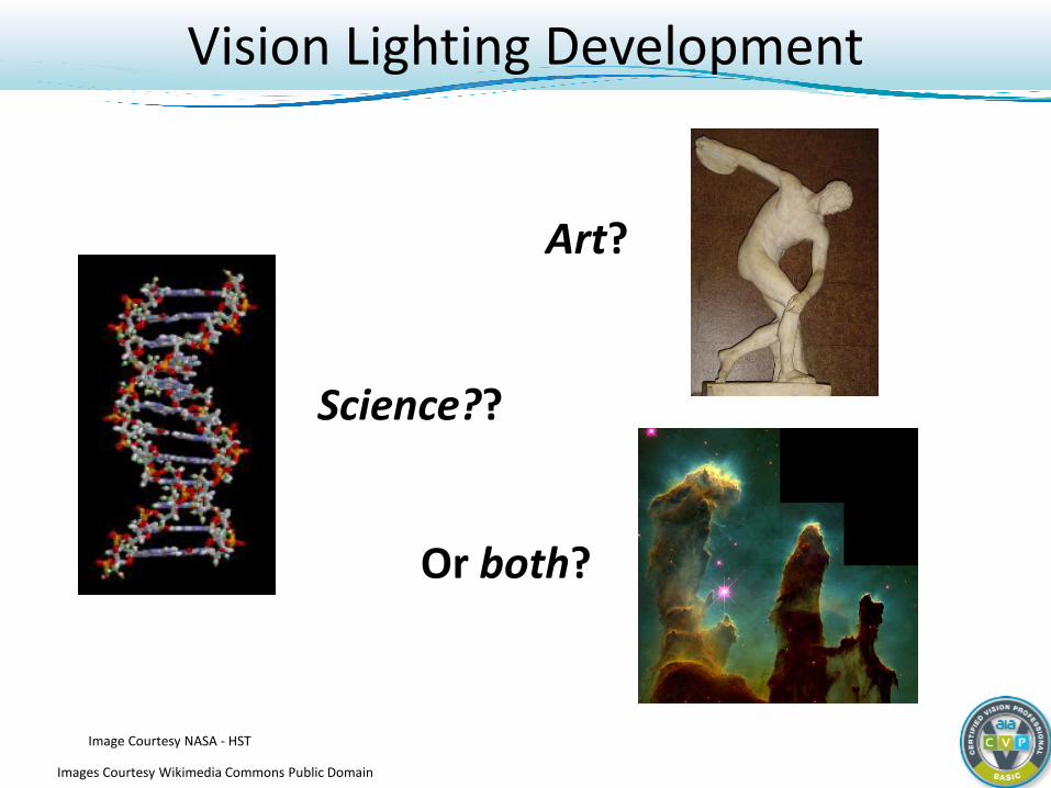
Art?
Or both?
Vision Lighting Development
Science??
Images Courtesy Wikimedia Commons Public Domain
Image Courtesy NASA - HST
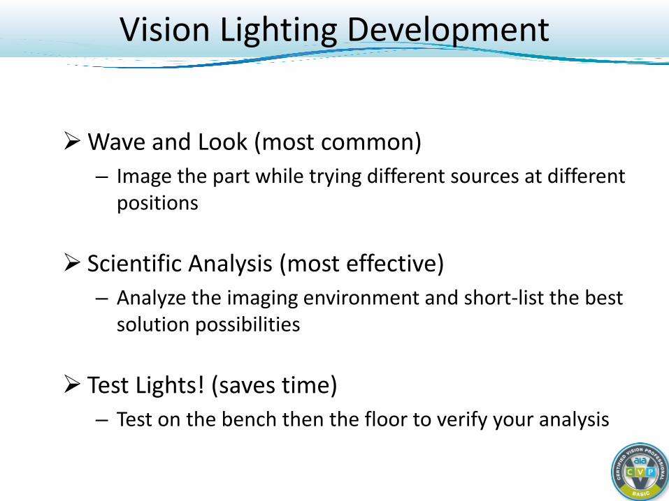
Wave and Look (most common) – Image the part while trying different sources at different
positions
Scientific Analysis (most effective) – Analyze the imaging environment and short-list the best
solution possibilities
Test Lights! (saves time) – Test on the bench then the floor to verify your analysis
Vision Lighting Development
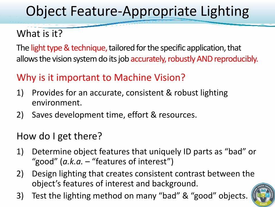
1) Provides for an accurate, consistent & robust lighting environment.
2) Saves development time, effort & resources.
Object Feature-Appropriate Lighting
The light type & technique, tailored for the specific application, that allows the vision system do its job accurately, robustly AND reproducibly.
Why is it important to Machine Vision?
What is it?
How do I get there? 1) Determine object features that uniquely ID parts as “bad” or
“good” (a.k.a. – “features of interest”) 2) Design lighting that creates consistent contrast between the
object’s features of interest and background. 3) Test the lighting method on many “bad” & “good” objects.
Review of Light for Vision Illumination
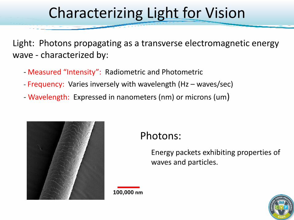
Characterizing Light for Vision
Light: Photons propagating as a transverse electromagnetic energy wave - characterized by: - Measured “Intensity”: Radiometric and Photometric - Frequency: Varies inversely with wavelength (Hz – waves/sec)
- Wavelength: Expressed in nanometers (nm) or microns (um)
Photons: Energy packets exhibiting properties of
waves and particles.
100,000 nm

400 nm 500 nm 600 nm 700 nm
UV Near IR
Human Visible Range
Decreasing Frequency
Decreasing Photon Energy Increasing Photometric Output
Increasing Wavelength
Increasing Penetration Depth*
Visible Light Spectrum
*For some sample materials, absorption bands may block longer wavelength penetration.
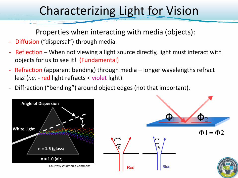
Characterizing Light for Vision Properties when interacting with media (objects):
- Diffusion (“dispersal”) through media.
- Reflection – When not viewing a light source directly, light must interact with objects for us to see it! (Fundamental)
- Refraction (apparent bending) through media – longer wavelengths refract less (i.e. - red light refracts < violet light).
- Diffraction (“bending”) around object edges (not that important).
n = 1.5 (glass)
n = 1.0 (air)
White Light
Angle of Dispersion
Courtesy Wikimedia Commons

Vision Lighting Sources
LED - Light Emitting Diode Quartz Halogen – W/ Fiber Optics Fluorescent Xenon (Strobing)
Vision Lighting Sources
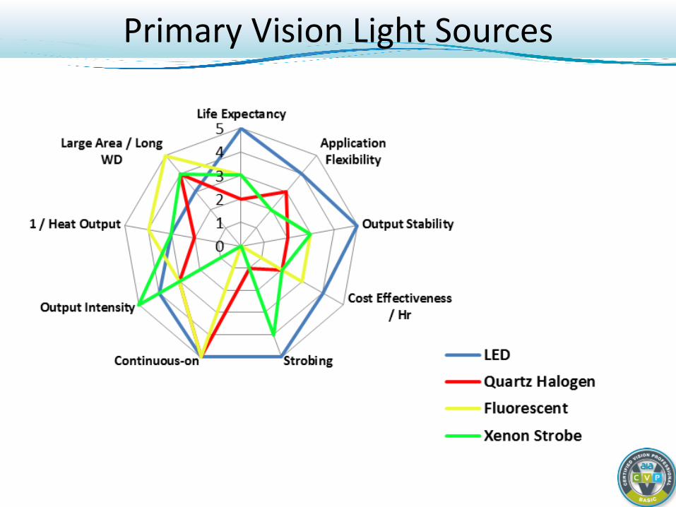
Primary Vision Light Sources
0
20
40
60
80
100
Rela
tive
Inte
nsity
(%)
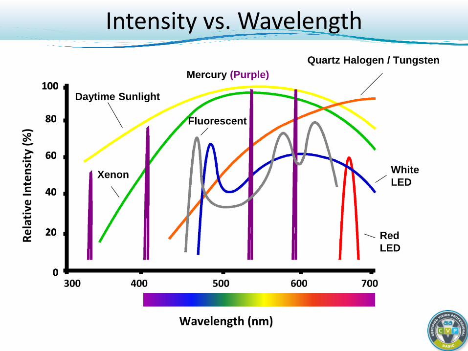
Intensity vs. Wavelength
Wavelength (nm)
300 400 500 600 700 0
20
40
60
80
100 Daytime Sunlight
Mercury (Purple) Quartz Halogen / Tungsten
Xenon White LED
Red LED
Fluorescent
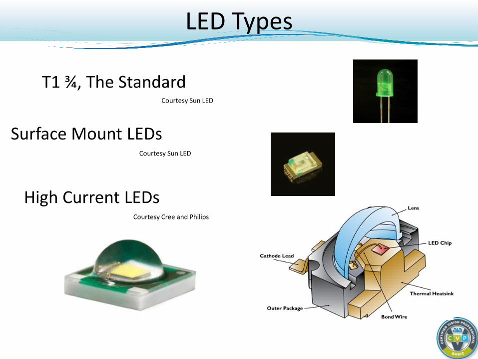
T1 ¾, The Standard Courtesy Sun LED
LED Types
Surface Mount LEDs Courtesy Sun LED
High Current LEDs Courtesy Cree and Philips
Light - Sample Interaction
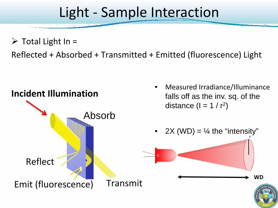
Total Light In = Reflected + Absorbed + Transmitted + Emitted (fluorescence) Light
Light - Sample Interaction
Incident Illumination
Reflect
Emit (fluorescence)
Absorb
Transmit WD
• Measured Irradiance/Illuminance falls off as the inv. sq. of the distance (I = 1 / r2)
• 2X (WD) = ¼ the “intensity”
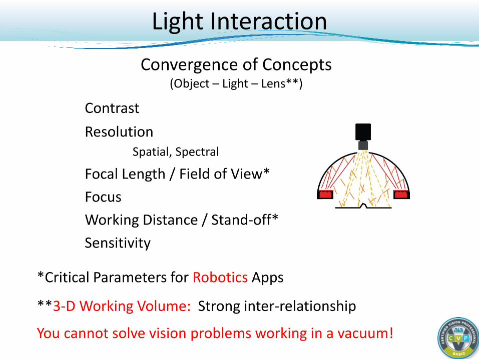
Convergence of Concepts (Object – Light – Lens**)
Contrast Resolution Spatial, Spectral
Focal Length / Field of View* Focus Working Distance / Stand-off* Sensitivity
*Critical Parameters for Robotics Apps
**3-D Working Volume: Strong inter-relationship
You cannot solve vision problems working in a vacuum!
Light Interaction
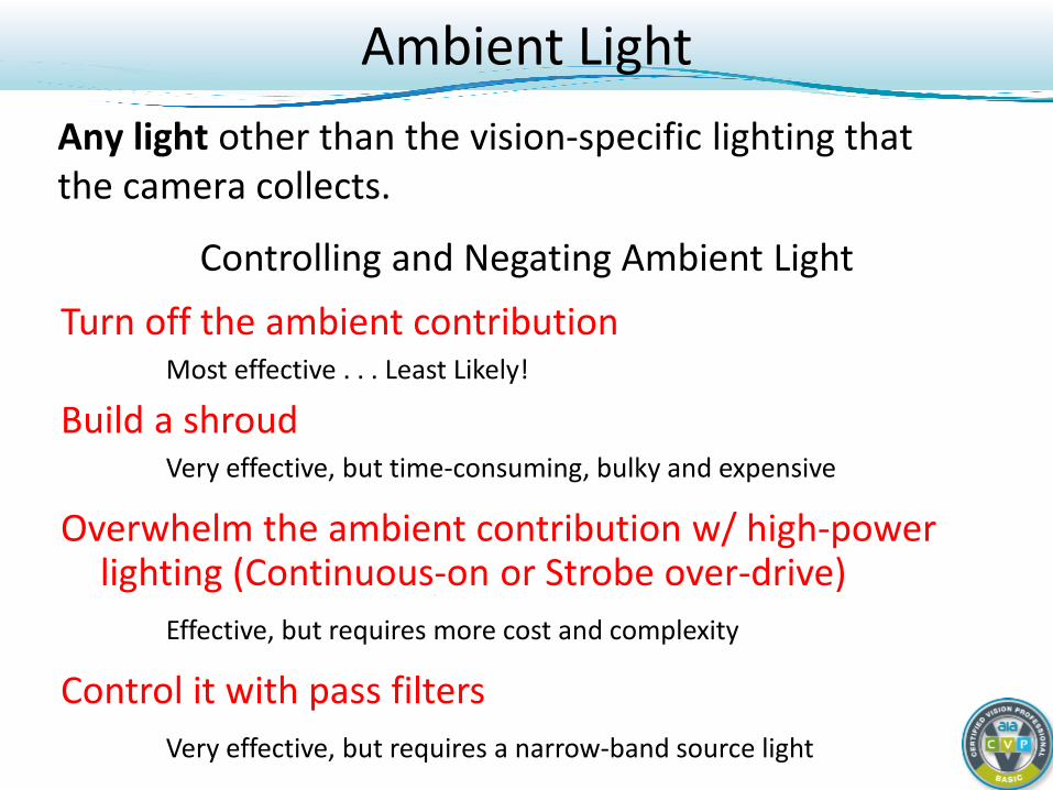
Controlling and Negating Ambient Light Turn off the ambient contribution Most effective . . . Least Likely!
Build a shroud Very effective, but time-consuming, bulky and expensive
Overwhelm the ambient contribution w/ high-power lighting (Continuous-on or Strobe over-drive)
Effective, but requires more cost and complexity
Control it with pass filters Very effective, but requires a narrow-band source light
Ambient Light Any light other than the vision-specific lighting that the camera collects.
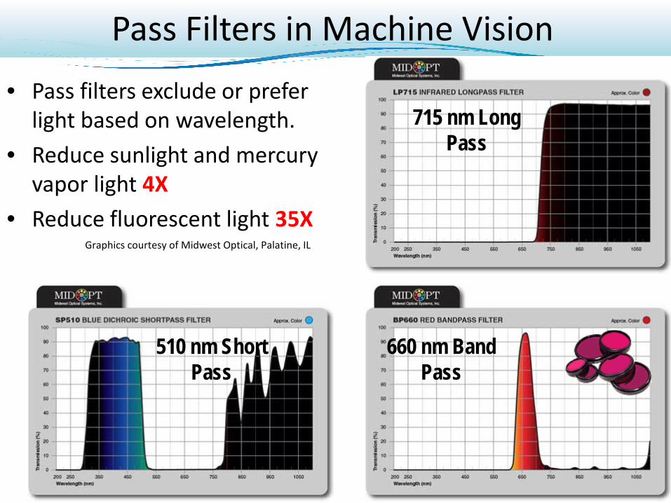
Pass Filters in Machine Vision • Pass filters exclude or prefer
light based on wavelength. • Reduce sunlight and mercury
vapor light 4X • Reduce fluorescent light 35X
715 nm Long Pass
660 nm Band Pass
510 nm Short Pass
Graphics courtesy of Midwest Optical, Palatine, IL
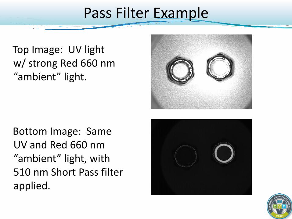
Top Image: UV light w/ strong Red 660 nm “ambient” light.
Bottom Image: Same
UV and Red 660 nm “ambient” light, with 510 nm Short Pass filter applied.
Pass Filter Example
Lighting Contrast
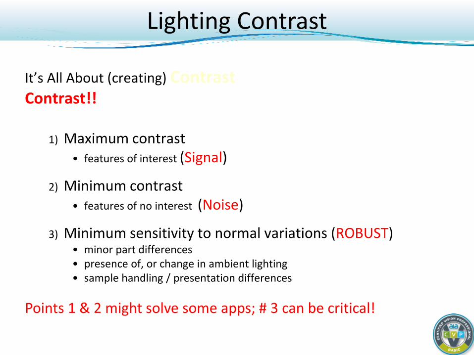
It’s All About (creating) Contrast Contrast!!
1) Maximum contrast • features of interest (Signal)
2) Minimum contrast • features of no interest (Noise)
3) Minimum sensitivity to normal variations (ROBUST) • minor part differences • presence of, or change in ambient lighting • sample handling / presentation differences
Points 1 & 2 might solve some apps; # 3 can be critical!
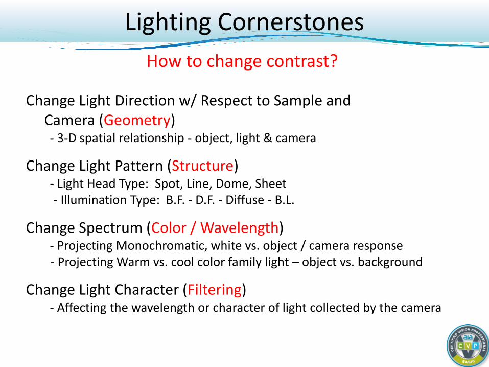
Change Light Direction w/ Respect to Sample and Camera (Geometry)
- 3-D spatial relationship - object, light & camera
Change Light Pattern (Structure) - Light Head Type: Spot, Line, Dome, Sheet
- Illumination Type: B.F. - D.F. - Diffuse - B.L.
Change Spectrum (Color / Wavelength) - Projecting Monochromatic, white vs. object / camera response
- Projecting Warm vs. cool color family light – object vs. background
Change Light Character (Filtering) - Affecting the wavelength or character of light collected by the camera
Lighting Cornerstones How to change contrast?
Light - Pickup Device Interaction
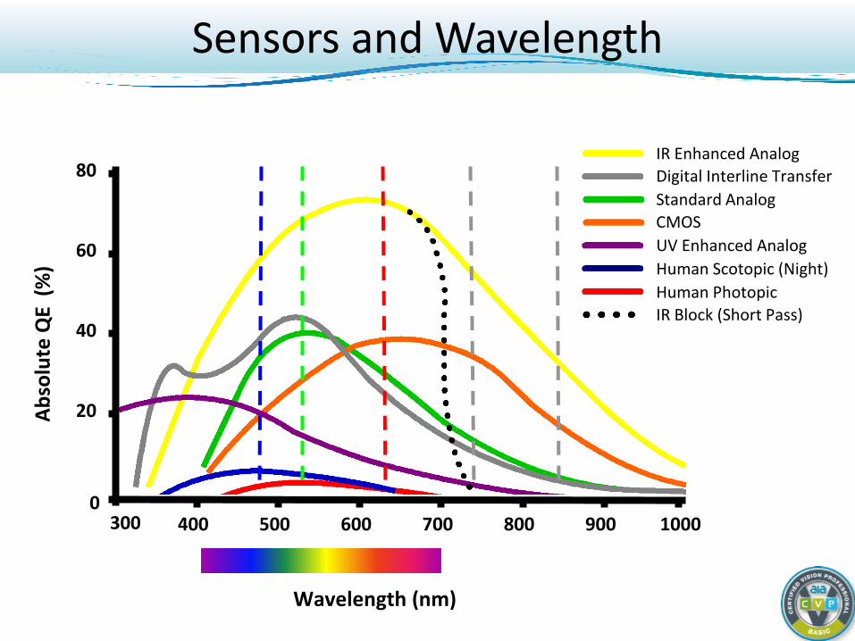
Sensors and Wavelength
Wavelength (nm)
300 400 500 600 700 0
20
40
60
80
Abso
lute
QE
(%)
800 900 1000
IR Enhanced Analog Digital Interline Transfer Standard Analog CMOS UV Enhanced Analog Human Scotopic (Night) Human Photopic IR Block (Short Pass)
Lighting Geometry Techniques
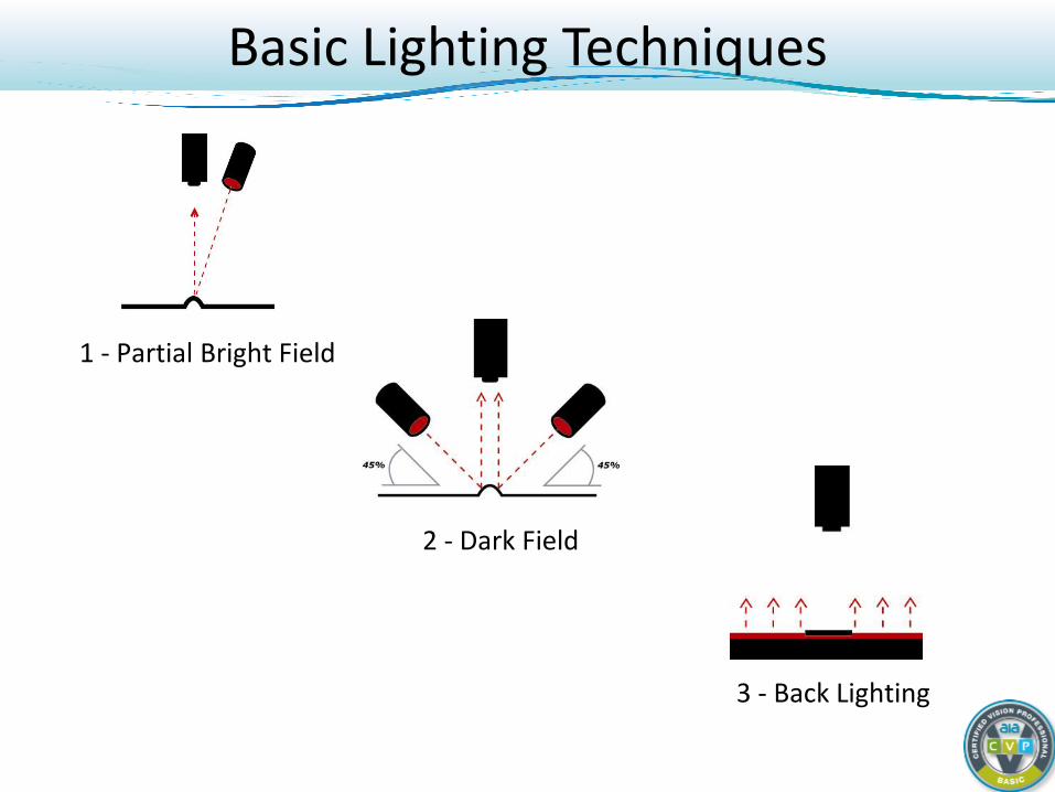
Basic Lighting Techniques
1 - Partial Bright Field
2 - Dark Field
3 - Back Lighting
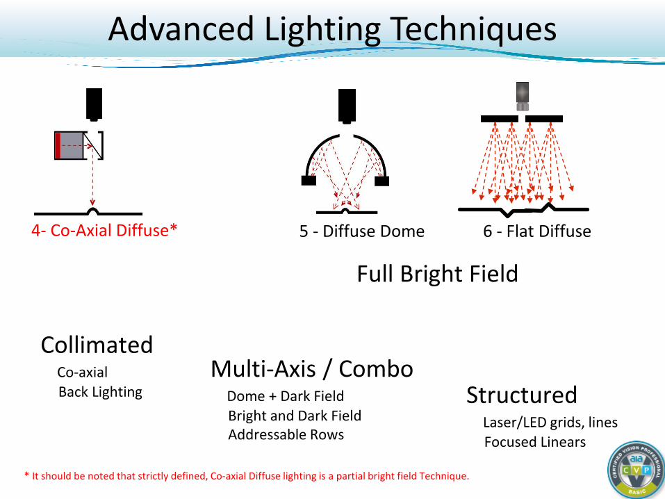
Advanced Lighting Techniques
Structured Laser/LED grids, lines Focused Linears
Full Bright Field
5 - Diffuse Dome 4- Co-Axial Diffuse* 6 - Flat Diffuse
Collimated Co-axial Back Lighting
Multi-Axis / Combo Dome + Dark Field Bright and Dark Field Addressable Rows
* It should be noted that strictly defined, Co-axial Diffuse lighting is a partial bright field Technique.
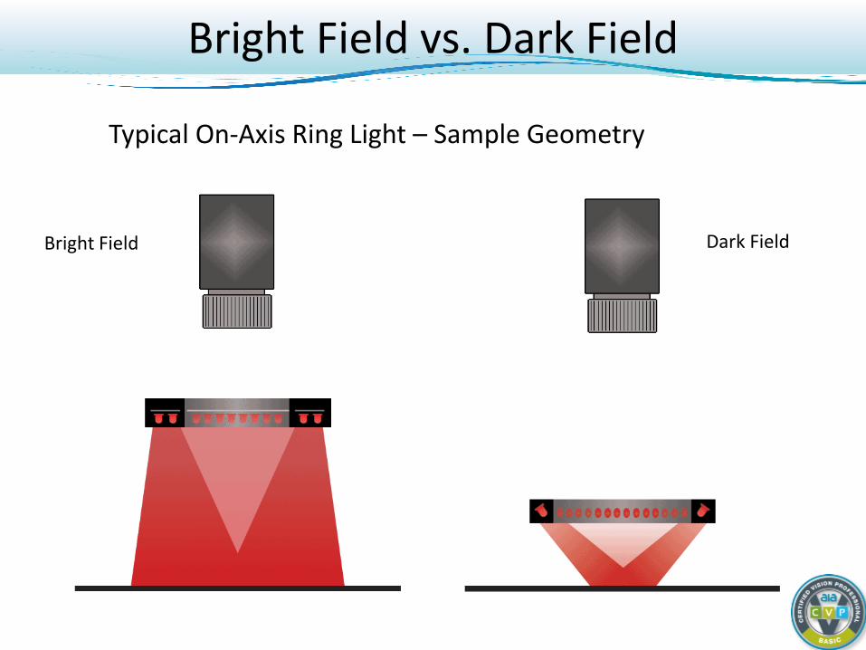
Typical On-Axis Ring Light – Sample Geometry
Bright Field
Bright Field vs. Dark Field
Dark Field
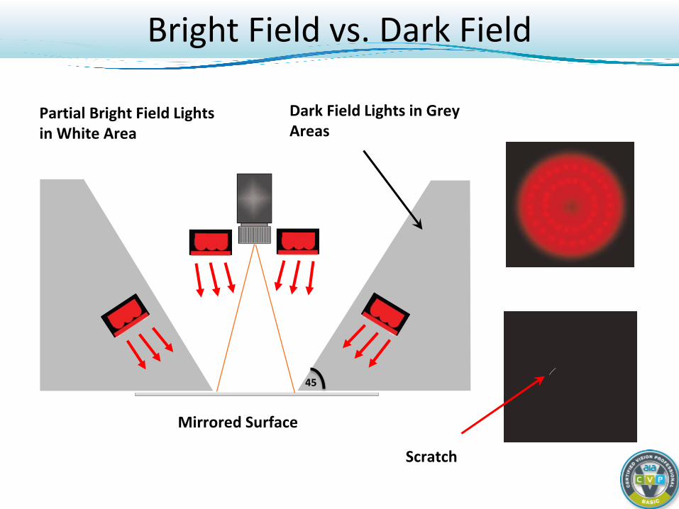
Dark Field Lights in Grey Areas
Mirrored Surface
Partial Bright Field Lights in White Area
Scratch
45
Bright Field vs. Dark Field
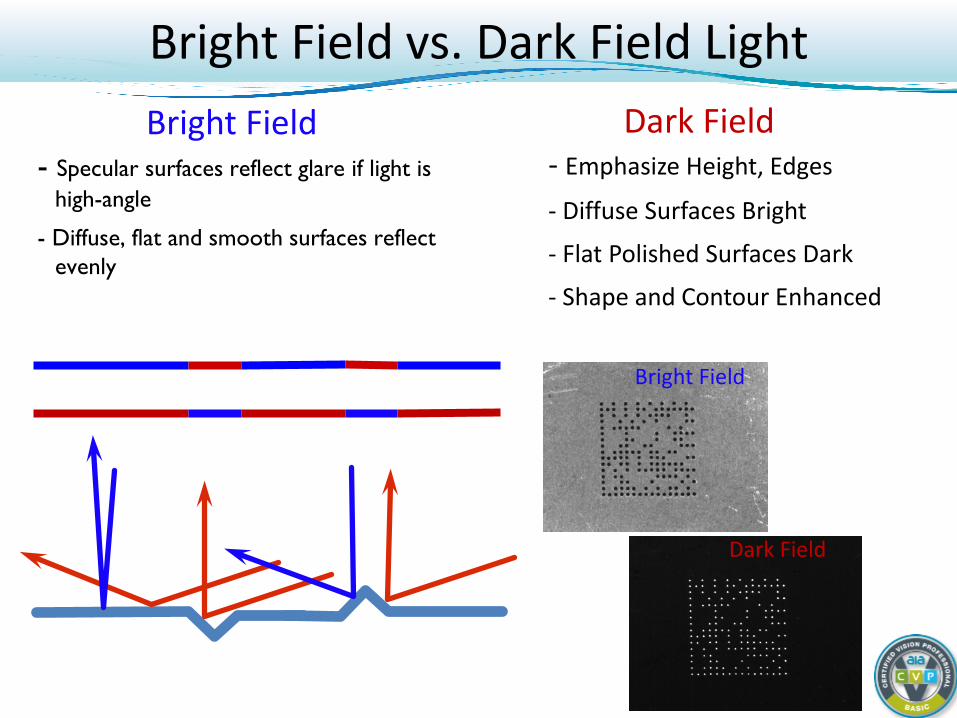
- Emphasize Height, Edges
- Diffuse Surfaces Bright
- Flat Polished Surfaces Dark
- Shape and Contour Enhanced
Dark Field - Specular surfaces reflect glare if light is
high-angle
- Diffuse, flat and smooth surfaces reflect evenly
Bright Field
Bright Field
Dark Field
Bright Field vs. Dark Field Light
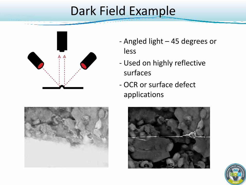
- Angled light – 45 degrees or less
- Used on highly reflective surfaces
- OCR or surface defect applications
Dark Field Example
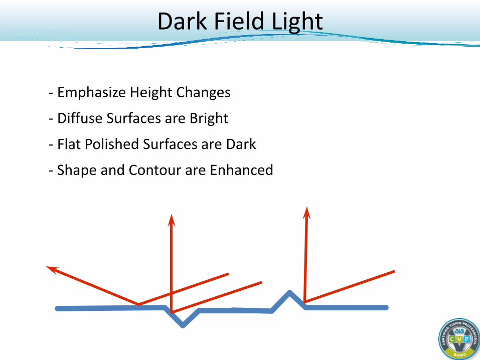
- Emphasize Height Changes
- Diffuse Surfaces are Bright
- Flat Polished Surfaces are Dark
- Shape and Contour are Enhanced
Dark Field Light

- Edge or hole detection - Useful on translucent
materials Liquid fill levels Glass/plastic cracks - Part P/A - Vision-Guided robotics – Pick
and Place - Gauging – Including high-
accuracy measurements
Back Lighting
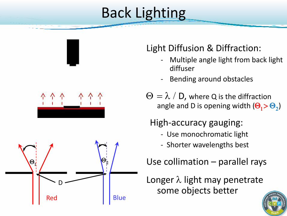
Light Diffusion & Diffraction: - Multiple angle light from back light
diffuser - Bending around obstacles
Θ = λ / D, where Q is the diffraction angle and D is opening width (Θ1> Θ2)
High-accuracy gauging: - Use monochromatic light - Shorter wavelengths best
Use collimation – parallel rays
Longer λ light may penetrate some objects better
Θ1
Red Blue
Θ2
Back Lighting
D
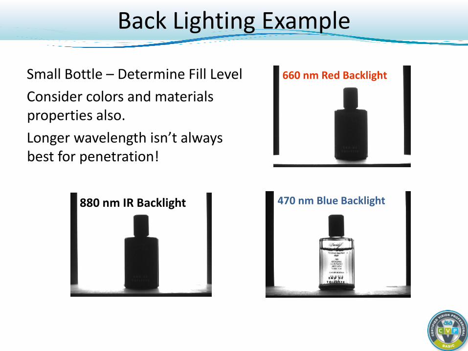
Small Bottle – Determine Fill Level Consider colors and materials properties also. Longer wavelength isn’t always best for penetration!
660 nm Red Backlight
880 nm IR Backlight 470 nm Blue Backlight
Back Lighting Example
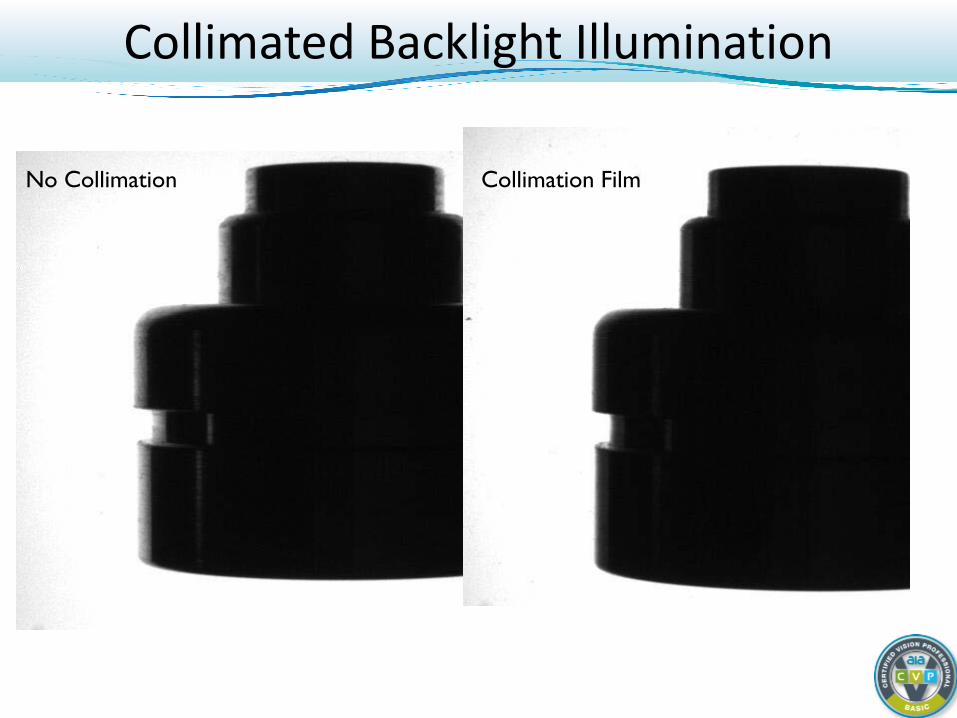
Collimated Backlight Illumination
No Collimation
Collimation Film
End of Part 1 = Break Time!
(Please be back in 10 mins . . .)
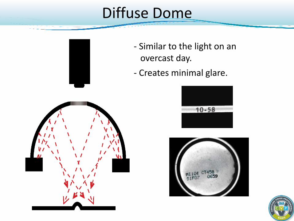
- Similar to the light on an overcast day. - Creates minimal glare.
Diffuse Dome
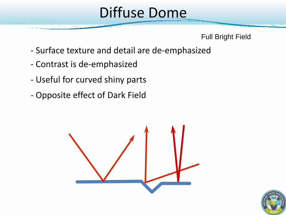
- Surface texture and detail are de-emphasized - Contrast is de-emphasized
- Useful for curved shiny parts
- Opposite effect of Dark Field
Full Bright Field
Diffuse Dome
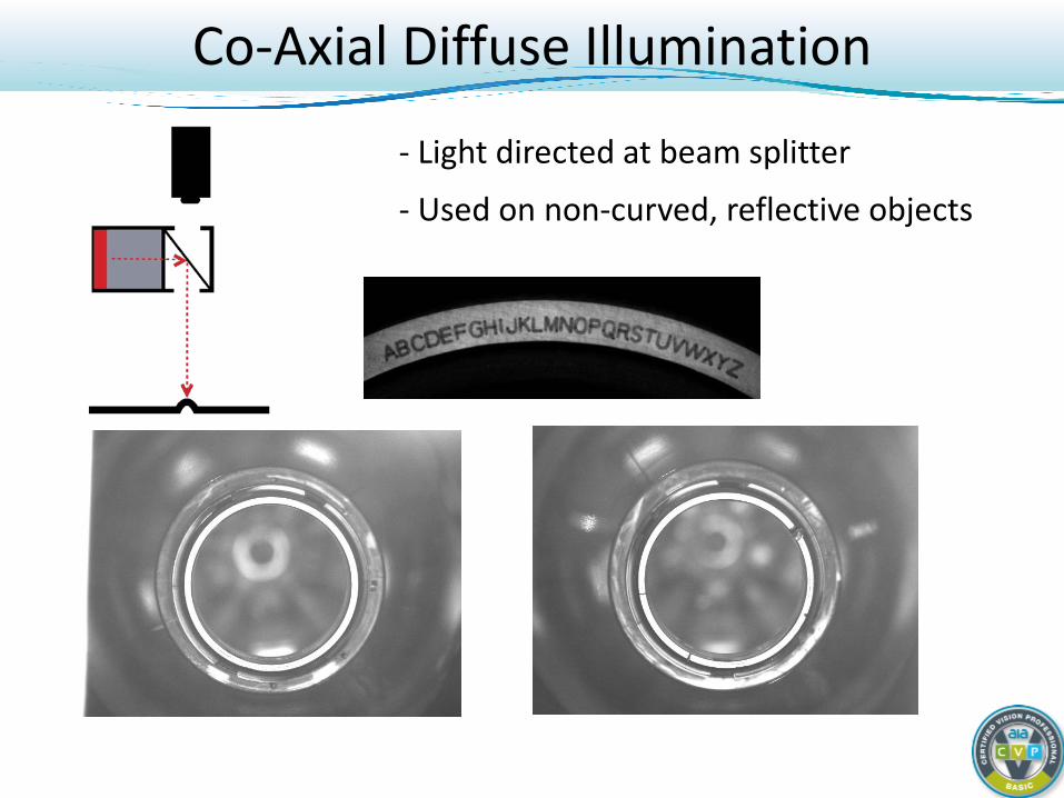
- Light directed at beam splitter
- Used on non-curved, reflective objects
Co-Axial Diffuse Illumination
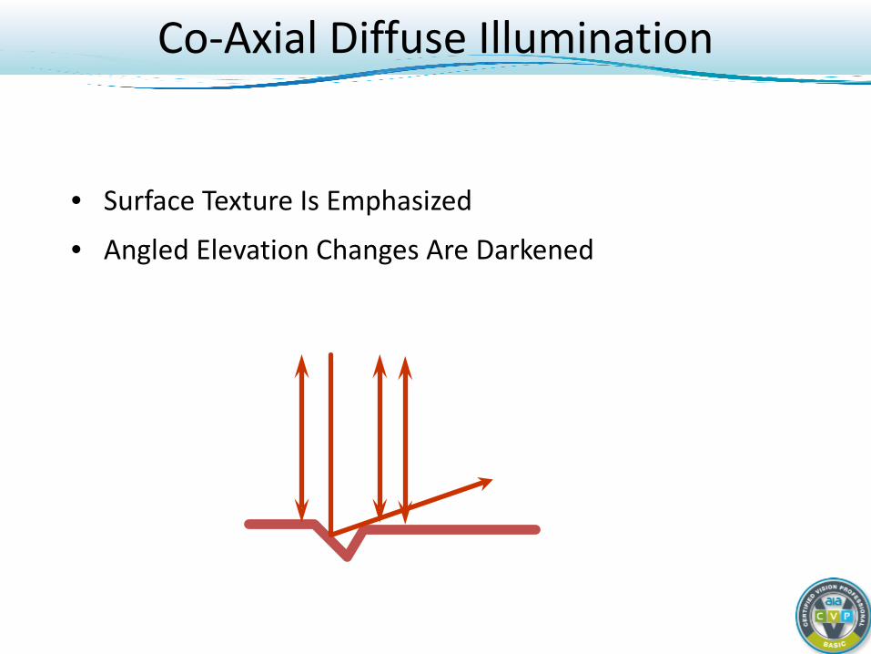
• Surface Texture Is Emphasized
• Angled Elevation Changes Are Darkened
Co-Axial Diffuse Illumination
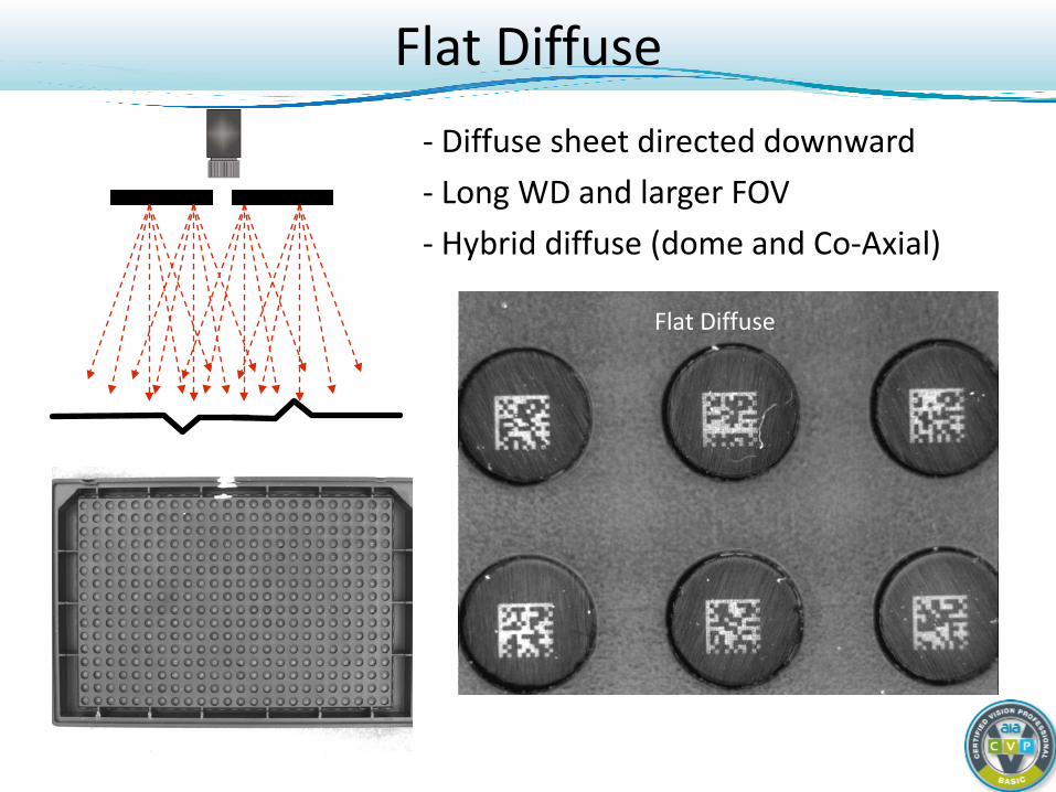
Flat Diffuse - Diffuse sheet directed downward - Long WD and larger FOV - Hybrid diffuse (dome and Co-Axial)
On-Axis BF Ring On-Axis DF Ring Diffuse Co-Axial Diffuse Dome Flat Diffuse
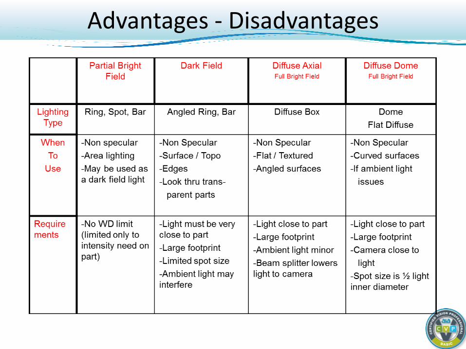
Advantages - Disadvantages
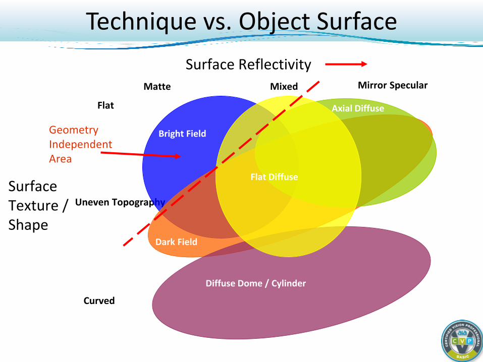
Technique vs. Object Surface Surface Reflectivity
Surface Texture / Shape
Matte Mixed Mirror Specular
Flat
Uneven Topography
Curved
Bright Field
Dark Field
Axial Diffuse
Diffuse Dome / Cylinder
Geometry Independent Area
Flat Diffuse
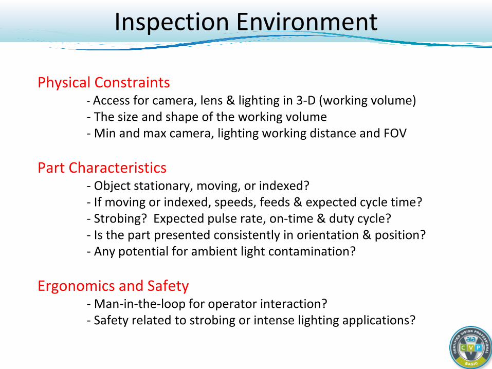
Inspection Environment
Physical Constraints - Access for camera, lens & lighting in 3-D (working volume) - The size and shape of the working volume - Min and max camera, lighting working distance and FOV Part Characteristics - Object stationary, moving, or indexed? - If moving or indexed, speeds, feeds & expected cycle time? - Strobing? Expected pulse rate, on-time & duty cycle? - Is the part presented consistently in orientation & position? - Any potential for ambient light contamination? Ergonomics and Safety - Man-in-the-loop for operator interaction? - Safety related to strobing or intense lighting applications?
Applications Examples
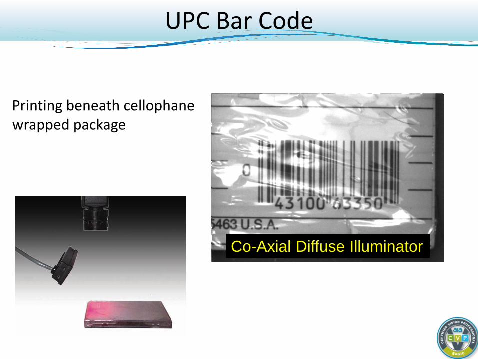
Printing beneath cellophane wrapped package
Off-Axis Broad Area Linear On-Axis Dark Field Ring Light On-Axis Bright Field Ring Light Co-Axial Diffuse Illuminator
UPC Bar Code
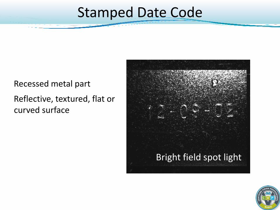
Recessed metal part
Reflective, textured, flat or curved surface
Dark Field ring light Line light Bright field ring light Bright field spot light
Stamped Date Code
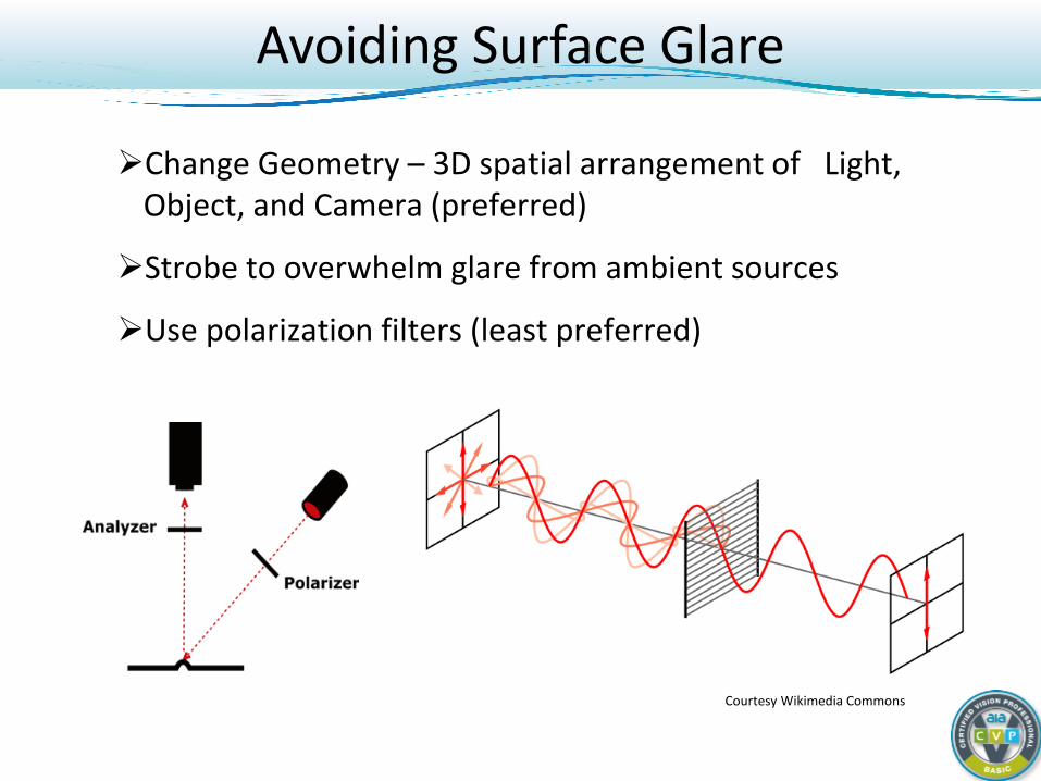
Avoiding Surface Glare
Change Geometry – 3D spatial arrangement of Light, Object, and Camera (preferred)
Strobe to overwhelm glare from ambient sources
Use polarization filters (least preferred)
Courtesy Wikimedia Commons
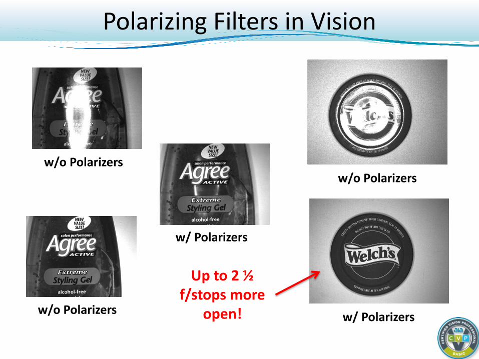
Polarizing Filters in Vision
w/o Polarizers
w/ Polarizers
w/o Polarizers
w/o Polarizers
w/ Polarizers
Up to 2 ½ f/stops more
open!
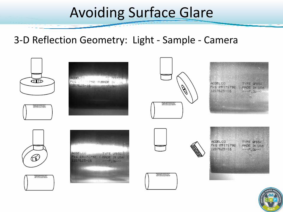
3-D Reflection Geometry: Light - Sample - Camera
Avoiding Surface Glare
Using Color and Wavelength
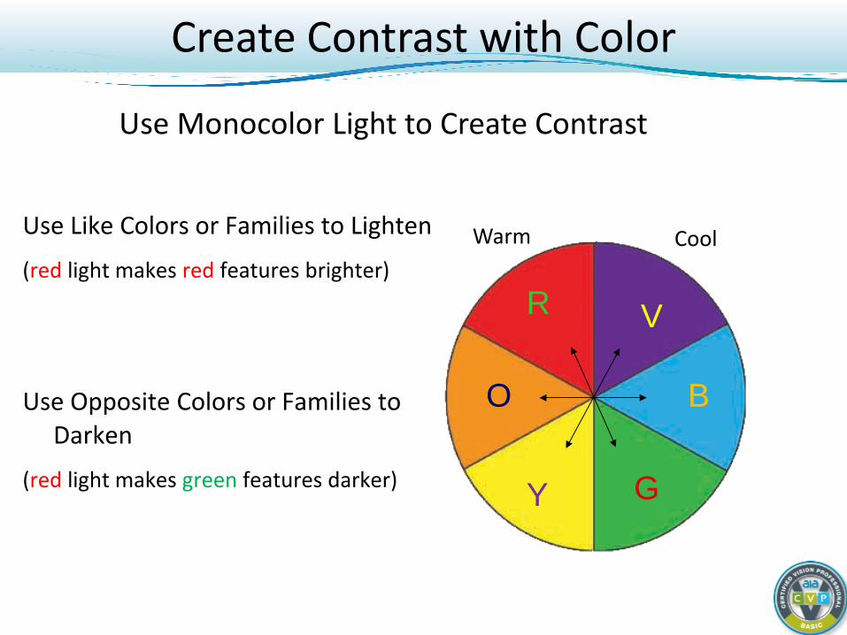
Use Monocolor Light to Create Contrast
Warm Cool
R V
O B
Y G
Create Contrast with Color
Use Like Colors or Families to Lighten (red light makes red features brighter)
Use Opposite Colors or Families to Darken
(red light makes green features darker)
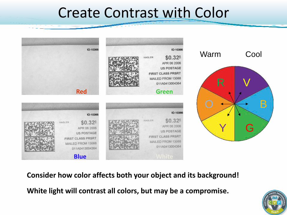
Red Green
Blue White
Consider how color affects both your object and its background!
White light will contrast all colors, but may be a compromise.
Warm Cool
R V
O B
Y G
Create Contrast with Color
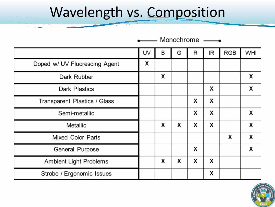
Wavelength vs. Composition
Imaging with Near IR and UV Light
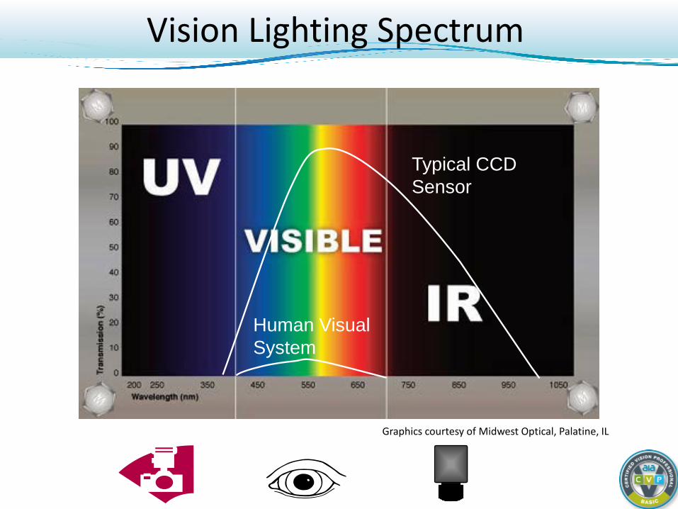
Vision Lighting Spectrum
Graphics courtesy of Midwest Optical, Palatine, IL
Typical CCD Sensor
Human Visual System
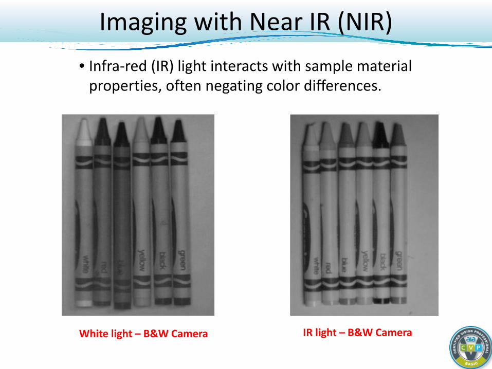
Imaging with Near IR (NIR) • Infra-red (IR) light interacts with sample material
properties, often negating color differences.
White light – B&W Camera IR light – B&W Camera
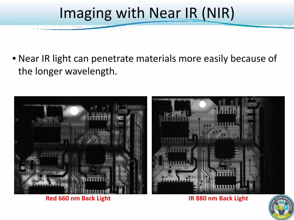
• Near IR light can penetrate materials more easily because of the longer wavelength.
Red 660 nm Back Light IR 880 nm Back Light
Imaging with Near IR (NIR)
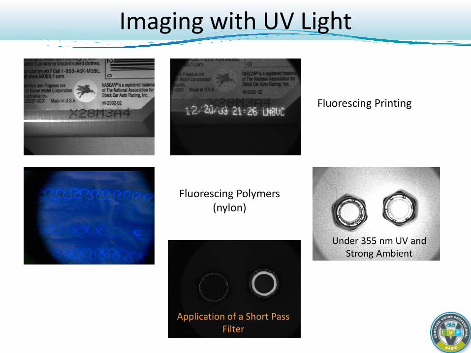
Imaging with UV Light
Fluorescing Printing
Fluorescing Polymers (nylon)
Under 355 nm UV and Strong Ambient
Application of a Short Pass Filter

Review and Summary
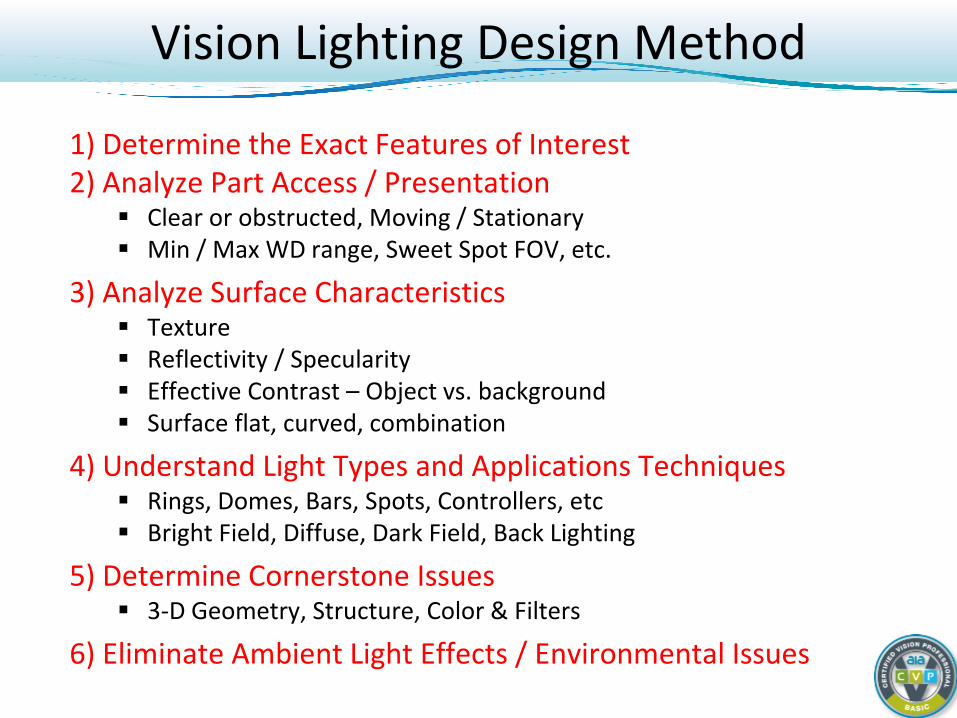
Vision Lighting Design Method
1) Determine the Exact Features of Interest 2) Analyze Part Access / Presentation
Clear or obstructed, Moving / Stationary Min / Max WD range, Sweet Spot FOV, etc.
3) Analyze Surface Characteristics Texture Reflectivity / Specularity Effective Contrast – Object vs. background Surface flat, curved, combination
4) Understand Light Types and Applications Techniques Rings, Domes, Bars, Spots, Controllers, etc Bright Field, Diffuse, Dark Field, Back Lighting
5) Determine Cornerstone Issues 3-D Geometry, Structure, Color & Filters
6) Eliminate Ambient Light Effects / Environmental Issues
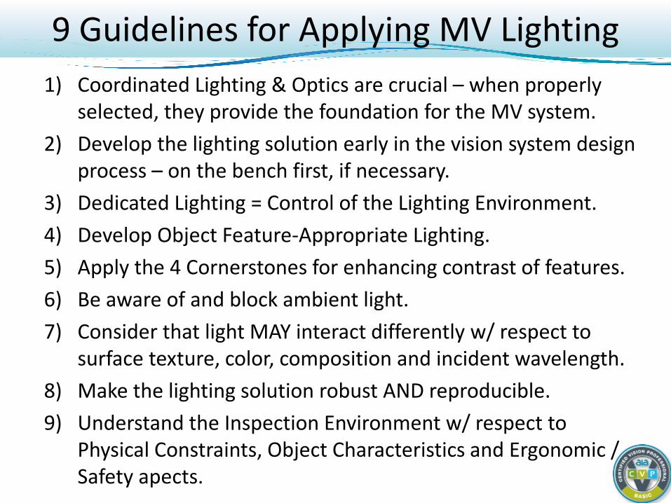
1) Coordinated Lighting & Optics are crucial – when properly selected, they provide the foundation for the MV system.
2) Develop the lighting solution early in the vision system design process – on the bench first, if necessary.
3) Dedicated Lighting = Control of the Lighting Environment. 4) Develop Object Feature-Appropriate Lighting. 5) Apply the 4 Cornerstones for enhancing contrast of features. 6) Be aware of and block ambient light. 7) Consider that light MAY interact differently w/ respect to
surface texture, color, composition and incident wavelength. 8) Make the lighting solution robust AND reproducible. 9) Understand the Inspection Environment w/ respect to
Physical Constraints, Object Characteristics and Ergonomic / Safety apects.
9 Guidelines for Applying MV Lighting
Contact Information
Daryl Martin Technical Sales & Product Manager
Advanced illumination, Inc. 440 State Garage Road Rochester, Vermont 05767 USA
Phone: +1 734-213-1312 Email: [email protected]
www.advancedillumination.com
Top Related