


Languages
Pages
Legal

University of HamburgFaculty of Mathematics,Informatics and Natural Sciences
Master Thesis
Basic Functionalities of a Grid-Infrastructurefor Service-Oriented Content Management
Christian Ewers
Course of study: Informatics
Matriculation number: 5417450
Hamburg, 06/27/2007
Tutors: Kathleen Krebs, Cataldo Mega
1st Advisor: Prof. Dr. Norbert Ritter
2nd Advisor: Dr. Heiko Rölke

Contents I
Contents
1 Introduction 11.1 Content Management Challenges . . . . . . . . . . . . . . . . . . . . . . . . 1
1.2 Content Management as a Service (CMaaS) . . . . . . . . . . . . . . . . . . 1
1.2.1 Email Archiving and Management (EAM) . . . . . . . . . . . . . . 2
1.2.2 Business Use Cases . . . . . . . . . . . . . . . . . . . . . . . . . . . . 2
1.2.3 Preliminary Work . . . . . . . . . . . . . . . . . . . . . . . . . . . . . 3
1.2.4 CMaaS Fields of Responsibility . . . . . . . . . . . . . . . . . . . . . 4
1.2.5 Next Steps - Applying Service Orientation and Automation . . . . 5
1.3 Thesis Objectives . . . . . . . . . . . . . . . . . . . . . . . . . . . . . . . . . 5
1.3.1 Thesis Structure . . . . . . . . . . . . . . . . . . . . . . . . . . . . . . 6
2 Technological Prerequisites 72.1 Content Management . . . . . . . . . . . . . . . . . . . . . . . . . . . . . . . 7
2.1.1 Enterprise Content Management (ECM) . . . . . . . . . . . . . . . . 7
2.1.2 Email Archiving and Management . . . . . . . . . . . . . . . . . . . 8
2.2 Trends in Enterprise IT Architectures . . . . . . . . . . . . . . . . . . . . . . 8
2.3 Service Orientation Concepts . . . . . . . . . . . . . . . . . . . . . . . . . . 9
2.3.1 The Service-Oriented Architecture (SOA) . . . . . . . . . . . . . . . 10
2.3.2 SOA Roles . . . . . . . . . . . . . . . . . . . . . . . . . . . . . . . . . 11
2.4 Grid Computing . . . . . . . . . . . . . . . . . . . . . . . . . . . . . . . . . . 12
2.4.1 The Idea Behind Grid Computing . . . . . . . . . . . . . . . . . . . 12
2.4.2 Open Grid Services Architecture - OGSA . . . . . . . . . . . . . . . 14
2.5 Web Services Resource Framework - WSRF . . . . . . . . . . . . . . . . . . 17
2.5.1 Sample Scenario . . . . . . . . . . . . . . . . . . . . . . . . . . . . . 17
2.5.2 Keeping State - The concept of a WS-Resource . . . . . . . . . . . . 19
2.5.3 WS-ServiceGroup (WSRF-SG) . . . . . . . . . . . . . . . . . . . . . . 21
2.5.4 WS-BaseNotification (WS-BN) . . . . . . . . . . . . . . . . . . . . . 21
2.5.5 Web Services Resource Metadata (WS-ResourceMetadataDescriptor) 22
2.6 Web Services Distributed Management (WSDM) . . . . . . . . . . . . . . . 23
2.6.1 WSDM-MUWS - Management Using Web Services . . . . . . . . . 23
2.7 Grid Computing in the IT Industry . . . . . . . . . . . . . . . . . . . . . . . 26
2.7.1 Utility Computing / Software as a Service / On-demand Computing 26
2.7.2 Service Level Agreements . . . . . . . . . . . . . . . . . . . . . . . . 27
2.8 Autonomic Computing . . . . . . . . . . . . . . . . . . . . . . . . . . . . . . 27
2.8.1 Properties of an Autonomic Computing System . . . . . . . . . . . 28
3 Requirement Specifications 31
II Contents
3.1 Scenario . . . . . . . . . . . . . . . . . . . . . . . . . . . . . . . . . . . . . . 31
3.1.1 Feature Requests for the EAM Service Solution . . . . . . . . . . . . 31
3.2 The CMaaS Approach . . . . . . . . . . . . . . . . . . . . . . . . . . . . . . 35
3.2.1 Applying Service-Orientation to the EAM System . . . . . . . . . . 35
3.2.2 Achieving System Manageability through Automation . . . . . . . 37
3.2.3 Applying Autonomic Computing Concepts . . . . . . . . . . . . . . 38
3.2.4 The Vision of an Autonomic, Service-Oriented Email Archiving Sys-
tem . . . . . . . . . . . . . . . . . . . . . . . . . . . . . . . . . . . . . 39
3.3 The Building Blocks of the EAMS Infrastructure . . . . . . . . . . . . . . . 40
3.3.1 Service Runtime . . . . . . . . . . . . . . . . . . . . . . . . . . . . . 42
3.3.2 Resource Management . . . . . . . . . . . . . . . . . . . . . . . . . . 44
3.3.3 System Automation . . . . . . . . . . . . . . . . . . . . . . . . . . . 48
3.4 Summary . . . . . . . . . . . . . . . . . . . . . . . . . . . . . . . . . . . . . . 51
4 Service Runtime Evaluation 53
4.1 The WSRF Basic Profile Specification . . . . . . . . . . . . . . . . . . . . . . 53
4.1.1 XML Processing in the Enterprise . . . . . . . . . . . . . . . . . . . 53
4.2 Evaluation of the WSRF Basic Profile (WSRF-BP) . . . . . . . . . . . . . . . 54
4.2.1 Handling State with WSRF . . . . . . . . . . . . . . . . . . . . . . . 54
4.2.2 Registry Service . . . . . . . . . . . . . . . . . . . . . . . . . . . . . . 56
4.2.3 Resource State Monitoring . . . . . . . . . . . . . . . . . . . . . . . . 57
4.2.4 Summary . . . . . . . . . . . . . . . . . . . . . . . . . . . . . . . . . 58
4.3 The Use of WSDM to Achieve Manageability . . . . . . . . . . . . . . . . . 59
4.3.1 Metrics and Metadata . . . . . . . . . . . . . . . . . . . . . . . . . . 59
4.3.2 A WSDM-based Resource Model . . . . . . . . . . . . . . . . . . . . 60
4.3.3 Summary . . . . . . . . . . . . . . . . . . . . . . . . . . . . . . . . . 62
4.4 Evaluation of WSRF Implementations . . . . . . . . . . . . . . . . . . . . . 62
4.4.1 Existing WSRF Implementations . . . . . . . . . . . . . . . . . . . . 62
4.4.2 Globus Toolkit 4 (GT4) . . . . . . . . . . . . . . . . . . . . . . . . . . 62
4.4.3 Apache Muse . . . . . . . . . . . . . . . . . . . . . . . . . . . . . . . 63
4.4.4 Performance Comparison . . . . . . . . . . . . . . . . . . . . . . . . 64
4.4.5 Programming Model . . . . . . . . . . . . . . . . . . . . . . . . . . . 65
4.4.6 Code Generation and Data Binding . . . . . . . . . . . . . . . . . . 67
4.4.7 Deployment . . . . . . . . . . . . . . . . . . . . . . . . . . . . . . . . 68
4.4.8 Additional Features . . . . . . . . . . . . . . . . . . . . . . . . . . . 71
4.4.9 Summary . . . . . . . . . . . . . . . . . . . . . . . . . . . . . . . . . 72
5 IBM Dynamic Infrastructure and WebSphere XD 73
5.1 IBM Dynamic Infrastructure (IDI) . . . . . . . . . . . . . . . . . . . . . . . . 73
5.1.1 On Demand Service . . . . . . . . . . . . . . . . . . . . . . . . . . . 73
5.1.2 The IBM DI Resource Model (DIRM) . . . . . . . . . . . . . . . . . . 74
Contents III
5.1.3 Order Processing . . . . . . . . . . . . . . . . . . . . . . . . . . . . . 76
5.1.4 The Life Cycle of an On Demand Service . . . . . . . . . . . . . . . 76
5.1.5 Service Life Cycle Management . . . . . . . . . . . . . . . . . . . . . 77
5.1.6 Tooling . . . . . . . . . . . . . . . . . . . . . . . . . . . . . . . . . . . 77
5.1.7 Summary . . . . . . . . . . . . . . . . . . . . . . . . . . . . . . . . . 78
5.2 IBM WebSphere Extended Deployment V6.0 (WXD) . . . . . . . . . . . . . 79
5.2.1 On Demand Router . . . . . . . . . . . . . . . . . . . . . . . . . . . . 79
5.2.2 Resource Sharing . . . . . . . . . . . . . . . . . . . . . . . . . . . . . 80
5.2.3 Service Policies . . . . . . . . . . . . . . . . . . . . . . . . . . . . . . 81
5.2.4 Work Classes . . . . . . . . . . . . . . . . . . . . . . . . . . . . . . . 82
5.2.5 Creation of Service Policies and Work classes . . . . . . . . . . . . . 82
5.2.6 Summary . . . . . . . . . . . . . . . . . . . . . . . . . . . . . . . . . 83
6 Implementation 856.1 Infrastructure . . . . . . . . . . . . . . . . . . . . . . . . . . . . . . . . . . . 85
6.1.1 Development Infrastructure . . . . . . . . . . . . . . . . . . . . . . . 85
6.1.2 Target infrastructure . . . . . . . . . . . . . . . . . . . . . . . . . . . 85
6.1.3 Testing Data . . . . . . . . . . . . . . . . . . . . . . . . . . . . . . . . 86
6.2 Implementation Architecture . . . . . . . . . . . . . . . . . . . . . . . . . . 86
6.2.1 Email Processing Workflow . . . . . . . . . . . . . . . . . . . . . . . 87
6.2.2 Common Capabilities . . . . . . . . . . . . . . . . . . . . . . . . . . 87
6.3 Implementation Details . . . . . . . . . . . . . . . . . . . . . . . . . . . . . . 89
6.3.1 PAI Service . . . . . . . . . . . . . . . . . . . . . . . . . . . . . . . . 89
6.3.2 ResourceFactory (Factory) . . . . . . . . . . . . . . . . . . . . . . . . 90
6.3.3 Dispatcher . . . . . . . . . . . . . . . . . . . . . . . . . . . . . . . . . 91
6.3.4 Advanced Registry . . . . . . . . . . . . . . . . . . . . . . . . . . . . 91
6.3.5 The Web Client . . . . . . . . . . . . . . . . . . . . . . . . . . . . . . 93
6.4 Summary . . . . . . . . . . . . . . . . . . . . . . . . . . . . . . . . . . . . . . 94
7 Conclusions and Further Lines of Investigation 95
List of Abbreviations 99
List of Figures 101
Listings 103
Bibliography 105
Trademarks 111
Affidavit 113

IV Contents
1
1 Introduction
Since the introduction of classical document management systems in the 1980s, the re-
quirements on solutions for handling electronic content in IT businesses evolved im-
mensely. From simple document digitizing to complex functionalities of today’s Enter-prise Content Management Systems (ECMS), the usage of electronic information revolution-
ized the office workflows.
By providing more and more functionalities, ECM systems often became very complex,
expensive and sometimes hard to manage applications in today’s IT infrastructures.
1.1 Content Management Challenges
With Content Management systems (CMS) originally designed for handling digitized
business letters, the amount of documents that had to be handled was modest and man-
ageable. Today’s ECM systems have to process documents, images, audio or even video
files. ECMS have to fulfill legal regulations like the Sarbanes-Oxley Act (SOX) of 20021
in the U.S. or the GDPdU in Germany of 20012. These regulations dictate, e.g. how long
business documents have to be archived and accessible for official inspections. As the
mandatory archiving duration of documents often exceeds a decade, these regulations
are driving the requirements on scalability aspects of ECMS higher and higher. The im-
mense amount of content, dictated to be archived, is causing a change in the field of
responsibilities of today’s ECMS. So far, as read-only access dominated overall requests,
ECMS were mostly optimized for search and retrieval aspects, to provide fast access to
documents. Now, ECMS have to provide high-performance document ingest capabilities
at the same time.
1.2 Content Management as a Service (CMaaS)
The University of Stuttgart (IPVS), IBM® (Böblingen, Germany) and the University of
Hamburg (VSIS) initiated a joint project that addresses the rising challenges of Enter-
prise Content Management. The Content Management as a Service (CMaaS) project has
the objective to develop a scalable, dynamic, automated and high-performance Content
Management solution, which can be offered by a Software as a Service (SaaS) approach
(see section 2.7.1). By this approach, customers can use a Content Management Service
without considering about infrastructure aspects like scaling or performance. The service
can just be requested with a to be defined Quality of Service (QoS). At the same time, the
1http://www.sarbanes-oxley.com2"Grundsätze zum Datenzugriff und zur Prüfbarkeit digitaler Unterlagen” (GDPdU) - available at
http://www.bundesfinanzministerium.de

2 1 Introduction
SaaS concept can implicate challenges for the service provider. These will be discussed
in more detail in chapter 3.
As an important and at the same time relatively self-contained aspect of ECM, EmailArchiving and Management (EAM) was chosen as a representative field of research for the
CMaaS project. A future attempt to generalize the research results from EAM to other
Content Management aspects is considered to be possible.
1.2.1 Email Archiving and Management (EAM)
Since the late 1990s the management of email messages became an important aspect of
ECM, as a lot of B2B (Business-to-Business) communication today is done via email. The
information, saved in email documents, has to be accessible for the enterprises them-
selves and has to fulfill the legal regulations stated above. From simple email archiving
and backup functionalities, Email Management today has to provide classification and or-
ganization functionalities to make access to emails more comfortable and compliant to
legal regulations.
Following an analysis by the Radicati Group3, corporate users sent and received 133 emails
per day in 2005. An increase of up to 160 emails per day in 2009 is expected, a vol-
ume grew by 20%. Taking an average size of 0.11MB per email, each user produces
14.7MB data that must be archived [Gro05]. For corporations with about 10,000 employ-
ees, around 150GB of emails must be handled per day. With the mentioned dictated
long-term archiving and accessibility regulations, scalability aspects of EAM systems are
becoming a real challenge. The CMaaS project tries to address these challenge by decom-
posing an EAMS into easy to manage components within a service-oriented system.
1.2.2 Business Use Cases
The aspects of adding to and retrieving emails from an EAMS can be considered as two
main usage scenarios of EAM. The upcoming use cases provide a short overview of these
two categories.
Ingest
The process of adding an email document to the EAM system is referred to as the ingestprocess or just ingest. The detailed description including the analysis of active components
during the ingest process are part of the master thesis by Malte Biß [Biß07]. The ingest
process can be categorized into automatic or manual ingest.
Automatic Ingest If the automatic ingest process is activated, the EAM system captures
all emails being received or sent over the used email servers and adds them to the
archive. With customizable filters, only specific categories like specific mailboxes
or department belongings can be selected for archiving.3The Radicati Group, Inc. - http://www.radicati.com
1.2 Content Management as a Service (CMaaS) 3
Manual Ingest A user selects a list of emails in his email client application that should
be archived and presses the archive button. This can be motivated by corporate reg-
ulations dictating maximum mailbox sizes per user. The archiving system retrieves
the selected emails from the email server and adds them to the archive. Due to sys-
tem configuration, the archived emails will be deleted completely from the email
server or replaced by lightweight so called stub-objects, which e.g. might contain an
excerpt of the email itself.
Retrieval
The retrieval process includes the tasks of searching a document in the archive and re-
trieving the document if the search was successful.
Regular Search and Retrieve If users need access to previously archived emails, they
can search the archive for the specific documents. As search keywords parts of the
subject, sender or even body text can be used. When the email has been found, it
can be opened directly or re-imported into the user’s mailbox.
Court case search In case of a legal inspection, a company may be forced to provide all
emails from the last year that satisfy a particular category. For this, the complete
archive will be searched and all matching emails retrieved.
The further discussion will mainly focus on the ingest process of EAM.
1.2.3 Preliminary Work
In a former project of IBM and the University of Stuttgart the scalability possibilities of
the IBM DB2® Content Manager4 (Content Manager) were evaluated. In general, the
Content Manager consists of a central catalog that handles metadata (Library Server) and
a set of possibly distributed content repositories (Resource Manager). As the scalability of
the central catalog depends on the used database, the first approach examined the scala-
bility possibilities based on the scaling functionalities of the underlying RDBMS. Details
and results of this approach can be found in [MWM05].
A completely different approach to achieve the required scale-out functionalities for gen-
eral Content Management systems is to distribute both central catalog and content repos-
itories to a cluster. By the separation and distribution of these two components a lot of
computational work needed for the catalog creation can be shifted to other resources. In
theory, this should lead to a system scalability almost linear to the number of used com-
puting nodes [WMM+07].
To prove the theoretical concepts, a prototype was developed which from now on will be
referred to as the cmgrid-prototype.
4http://www-306.ibm.com/software/data/cm/cmgr/mp/ - 05/2007
4 1 Introduction
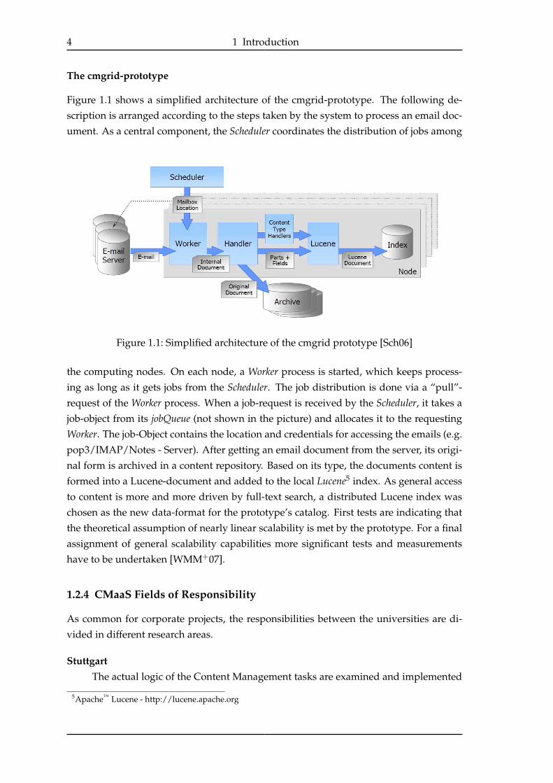
The cmgrid-prototype
Figure 1.1 shows a simplified architecture of the cmgrid-prototype. The following de-
scription is arranged according to the steps taken by the system to process an email doc-
ument. As a central component, the Scheduler coordinates the distribution of jobs among
Figure 1.1: Simplified architecture of the cmgrid prototype [Sch06]
the computing nodes. On each node, a Worker process is started, which keeps process-
ing as long as it gets jobs from the Scheduler. The job distribution is done via a “pull”-
request of the Worker process. When a job-request is received by the Scheduler, it takes a
job-object from its jobQueue (not shown in the picture) and allocates it to the requesting
Worker. The job-Object contains the location and credentials for accessing the emails (e.g.
pop3/IMAP/Notes - Server). After getting an email document from the server, its origi-
nal form is archived in a content repository. Based on its type, the documents content is
formed into a Lucene-document and added to the local Lucene5 index. As general access
to content is more and more driven by full-text search, a distributed Lucene index was
chosen as the new data-format for the prototype’s catalog. First tests are indicating that
the theoretical assumption of nearly linear scalability is met by the prototype. For a final
assignment of general scalability capabilities more significant tests and measurements
have to be undertaken [WMM+07].
1.2.4 CMaaS Fields of Responsibility
As common for corporate projects, the responsibilities between the universities are di-
vided in different research areas.
StuttgartThe actual logic of the Content Management tasks are examined and implemented
5Apache™ Lucene - http://lucene.apache.org

1.3 Thesis Objectives 5
by the team in Stuttgart. Concepts like index distribution, data model or distributedsearch are part of their field of responsibility.
HamburgThe CMaaS team in Hamburg examines how concepts like Software as a Service,
service orientation or automatic provisioning can be applied to Content Management.
1.2.5 Next Steps - Applying Service Orientation and Automation
While the team in Stuttgart focuses on the challenges of high-performance and scala-
bility, the CMaaS team in Hamburg faces the aspects of service orientation and system
automation. The thesis Componentization and Orchestration of Content Management Ser-vices by Malte Biß [Biß07], analyzes the possibilities of how to divide so-called ContentManagement components into Content Management services and how these services can be
orchestrated to create an EAM service. The results of that work will be used in this thesis
in order to identify infrastructure requirements.
The specific objectives of this thesis are presented in the next section.
1.3 Thesis Objectives
From a business perspective, the Software as a Service (SaaS, see section 2.7.1) concept
seems to be a suitable approach for an Email Archiving and Management System (EAMS).
Service consumers only pay for service consumption (email archiving) and do not have
to handle the complexity of EAM systems with respect to the underlying runtime envi-
ronment and IT infrastructure. The service provider is completely responsible for cop-
ing with the challenges of scalability, performance and system management to maintain
the guaranteed Quality of Service (QoS). The infrastructure used by the provider as the
basis for the EAM system has a great influence on how flexibly, dynamically and au-
tonomously the system will run.
Different infrastructure solutions have to be analyzed by this thesis. As a project member,
IBM is interested in the possibility of using the IBM products IBM Dynamic Infrastructure(IDI) and IBM WebSphere® Extended Deployment (WXD) as infrastructure components for
the intended EAM system. In addtion to this, available standards and open-source solu-
tions from the Grid computing area shall be examined.
This thesis will answer the central question:
Are the above mentioned systems and standards capable of forming the infras-tructure for the intended EAM system?
The theoretical results have to be evaluated with an implementation of a simple proto-
type.
6 1 Introduction
1.3.1 Thesis Structure
After this introduction, an overview of the technological prerequisites like service ori-
entation and Grid computing is given in chapter 2. Before the stated products can be
evaluated, the requirements on the infrastructure demanded by a service oriented EAM
system will be analyzed and discussed in chapter 3. The standards WSRF and WSDM
and their implementations by the Globus Toolkit 4 and Apache Muse are evaluated in chap-
ter 4. Chapter 5 will discuss the integrated solutions IBM Dynamic Infrastructure and IBMWebSphere Extended Deployment. Based on the evaluation a prototype was implemented
to test the theoretical results. The design and other implementation details are presented
in chapter 6. Conclusions and an outlook on further research directions in the CMaaS
project in chapter 7 are closing this thesis.

7
2 Technological Prerequisites
This thesis analyzes the infrastructure requirements for a service oriented Content Man-
agement system and evaluates solutions of the Grid computing field. To do this, the
terms SOA, Content Management, Grid computing and other technologies needed for this
thesis will be introduced in this chapter. The Grid computing and Web Services related
standards WSRF and WSDM will be examined in detail, as they are essential for many
parts of this thesis. A short introduction to Autonomic Computing concepts will close this
chapter, as these are needed during the requirements process in chapter 3.
2.1 Content Management
The CMaaS project wants to develop a next generation Content Management solution. Be-
fore discussing the resulting infrastructure requirements, the term Content Management(CM) has to be introduced first. This introduction will only provide a short overview
of Content Management, as a detailed knowledge of specific Content Management pro-
cesses is not needed for this thesis. For more information about CM, the reader is referred
to [VOI05] or [GSM+01].
In general, the area of Content Management addresses the computational handling of
arbitrary content. From classical Document Management Systems to today’s Enterprise Con-tent Management Systems, the handled content has been extended from simple digitized
or electronic text-documents, to emails, images and even videos.
Document Management (DM) offers integrated management functionalities for the life-cycle of a document. With the usage of a Document Management System (DMS) a central
repository for all documents of a company is provided.
2.1.1 Enterprise Content Management (ECM)
With the move from DM to ECM, the processed content is expanded from real documentsto content in a more general matter. Enterprise Content Management Systems (ECMS)
have to manage even video or audio-files and integrate them in a way, that a real infor-
mation benefit is created. By talking about Enterprise CM, the usage of an ECM within an
enterprise as the central infrastructure for content and information shall be emphasized
[VOI05]. The Association for Information and Image Management (AIIM)1 associates ECM to
the technologies that are used to "capture, manage, store, preserve, and deliver content anddocuments related to organizational processes."
1http://www.aiim.org

8 2 Technological Prerequisites
CaptureThe capture category combines functionalities and components for generating, cap-
turing, preparing and processing analog and electronic information. This includes
technologies like digital imaging, text recognition or indexing.
IndexingIndexing is an important aspect of content capturing. During the index process,
metadata documents are created so that documents can be found. Indexing
can be based on keywords or full-text. The term indexing will be used a lot
in this thesis, as the architecture used in the CMaaS project uses a distributed
indexing approach to achieve improved scalability.
ManageThe manage category combines the components Document Management, Collabo-
ration, Web Content Management, Records Management and Workflow / Business
Process Management.
StoreComponents of the store category are used for the storage of information that is not
required to archive on long-term storage.
PreserveLong-term and safe storage and backup of information is combined in the preservecategory.
DeliverComponents that are responsible to present information handled by the other four
categories are classified to the deliver category.
2.1.2 Email Archiving and Management
The aspect of email archiving and management (EAM) is one important aspect of ECM.
With the still immensely growing amount of emails (see 1.2.1) the requirements on EAM
systems are getting harder to fulfill. This thesis focuses on the EAM process referred
to as the ingest process which can be compared with the general ECM processes captureand store. The ingest process contains e.g. the tasks parsing, de-duplication, compliancescanning, indexing and archiving of emails. For a detailed discussion of these tasks, the
reader is referred to [Biß07].
2.2 Trends in Enterprise IT Architectures
Since the first usage of computers in enterprises, the IT architectures have changed enor-
mously. In the beginning, all used applications ran on a mainframe and were con-
trolled from dumb computer terminals. The mainframe offered the possibility to serve
many applications simultaneously with integrated resource and workload management,
2.3 Service Orientation Concepts 9
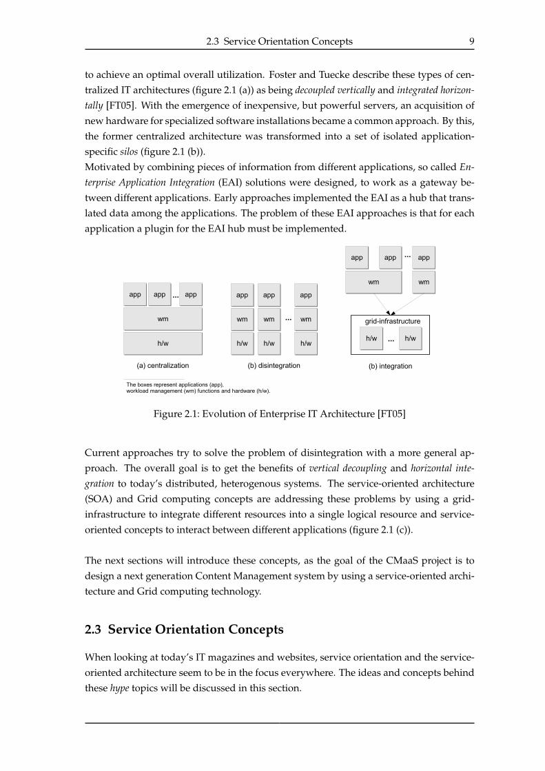
to achieve an optimal overall utilization. Foster and Tuecke describe these types of cen-
tralized IT architectures (figure 2.1 (a)) as being decoupled vertically and integrated horizon-tally [FT05]. With the emergence of inexpensive, but powerful servers, an acquisition of
new hardware for specialized software installations became a common approach. By this,
the former centralized architecture was transformed into a set of isolated application-
specific silos (figure 2.1 (b)).
Motivated by combining pieces of information from different applications, so called En-terprise Application Integration (EAI) solutions were designed, to work as a gateway be-
tween different applications. Early approaches implemented the EAI as a hub that trans-
lated data among the applications. The problem of these EAI approaches is that for each
application a plugin for the EAI hub must be implemented.
Figure 2.1: Evolution of Enterprise IT Architecture [FT05]
Current approaches try to solve the problem of disintegration with a more general ap-
proach. The overall goal is to get the benefits of vertical decoupling and horizontal inte-gration to today’s distributed, heterogenous systems. The service-oriented architecture
(SOA) and Grid computing concepts are addressing these problems by using a grid-
infrastructure to integrate different resources into a single logical resource and service-
oriented concepts to interact between different applications (figure 2.1 (c)).
The next sections will introduce these concepts, as the goal of the CMaaS project is to
design a next generation Content Management system by using a service-oriented archi-
tecture and Grid computing technology.
2.3 Service Orientation Concepts
When looking at today’s IT magazines and websites, service orientation and the service-
oriented architecture seem to be in the focus everywhere. The ideas and concepts behind
these hype topics will be discussed in this section.

10 2 Technological Prerequisites
2.3.1 The Service-Oriented Architecture (SOA)
The key element behind the concept of service orientation is, of course, the service itself.
Service Newcomer and Lomow describe services from two different perspectives, the
business and the technical perspective. From a business perspective, services rep-
resent and correspond to business activities or functions that can be accessed ac-
cording to established service-specific policies. Technically, services are reusable
components with well-defined interfaces that abstract from the internal implemen-
tation and allow the decoupling of service provider and service requester [NL04].
When looking at definitions for SOA [PW05],[SDt06],[NL04], many of them vary in de-
tails, although sharing the same key concepts, combined by the following definition,
which will be used within this thesis.
Service-Oriented Architecture (SOA) A service-oriented architecture is an architectural
style that enables the composition of distributed capabilities by the use of standard-
ized, loosely coupled services through well-defined interfaces.
From a business perspective, these loosely coupled services represent business function-
alities which are made available and form the building blocks of current and future busi-
ness applications [Coh06]. When talking about horizontal integration, SOA does not try
to brake the architecture of disintegrated data silos, but offers the data as services. These
data services can be used and combined by applications (which can be services itself), to
create a new federated view on the underlying data.
Advantages and Disadvantages of a SOA
A service oriented architecture promises to offer many advantages for enterprises, but
comes with a set of disadvantages too. The following paragraph will outline some of
them. For more information about the advantages and disadvantages of a SOA, the
reader is referred to [NL04], [Coh06].
Advantages
• A SOA offers a flexible and comfortable solution for information and application
integration.
• By using standardized interfaces, a service can be accessed from a variety of users
and applications.
• By composing business services out of fine grained services, a simple reconfigura-
tion and adaptation of existing business processes is possible.
2.3 Service Orientation Concepts 11
Disadvantages
• When composing applications out of services, the availability of these services be-
comes critical for the proper functionality of the application.
• The advantage of being able to use external services entails issues like quality as-
pects of the delivered data. The reliability and trustworthiness of the external ser-
vice now has a great influence on one’s own application.
2.3.2 SOA Roles
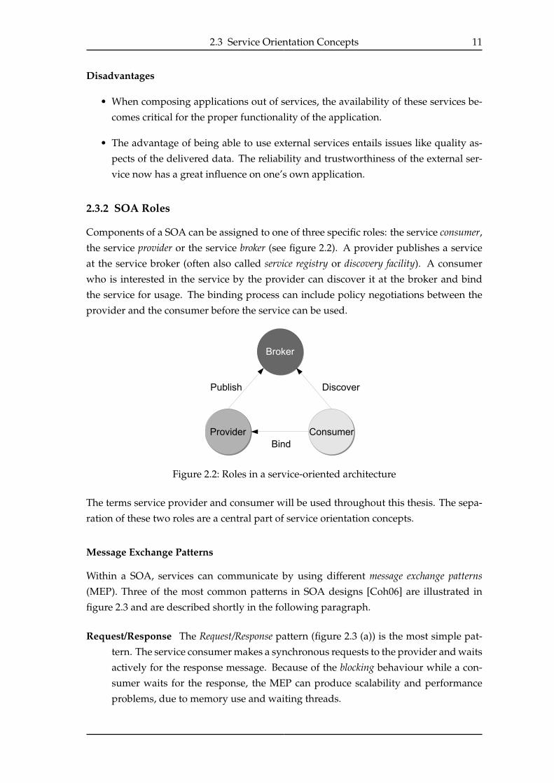
Components of a SOA can be assigned to one of three specific roles: the service consumer,
the service provider or the service broker (see figure 2.2). A provider publishes a service
at the service broker (often also called service registry or discovery facility). A consumer
who is interested in the service by the provider can discover it at the broker and bind
the service for usage. The binding process can include policy negotiations between the
provider and the consumer before the service can be used.
Figure 2.2: Roles in a service-oriented architecture
The terms service provider and consumer will be used throughout this thesis. The sepa-
ration of these two roles are a central part of service orientation concepts.
Message Exchange Patterns
Within a SOA, services can communicate by using different message exchange patterns(MEP). Three of the most common patterns in SOA designs [Coh06] are illustrated in
figure 2.3 and are described shortly in the following paragraph.
Request/Response The Request/Response pattern (figure 2.3 (a)) is the most simple pat-
tern. The service consumer makes a synchronous requests to the provider and waits
actively for the response message. Because of the blocking behaviour while a con-
sumer waits for the response, the MEP can produce scalability and performance
problems, due to memory use and waiting threads.

12 2 Technological Prerequisites
Figure 2.3: Popular message exchange patterns in SOA designs
Publish/Subscribe When using a Publish/Subscribe pattern (figure 2.3 (b)), the service
provider offers a set of methods for the consumer to register for a set of messages.
Whenever the provider gets information the consumer is interested in, he sends a
message (publishes) to the consumer. If a consumer is not interested in the infor-
mation any longer, he can unsubscribe his registration.
Broadcast A Broadcast MEP (figure 2.3 (c)) is used whenever a broad set of consumers is
interested in a specific information-topic. In this MEP the provider sends messages
without expecting any responses. A variation of the Broadcast MEP is the MulticastMEP, in which not all but a group of consumers are notified automatically by the
provider.
2.4 Grid Computing
While SOA addresses the challenge of horizontal integration of applications (see section
2.2), the Grid computing concept can be assigned to the aspect of the horizontal integrationof hardware resources.
This thesis will evaluate how concepts and technologies related to Grid computing can
be used within the CMaaS project. The ideas, standards and concepts of Grid computing
will be introduced in the following sections.
2.4.1 The Idea Behind Grid Computing
With the overall idea of providing access to computing power as easily as people can
access electricity through the electric power grid today, Ian Foster2 introduced the term
computational Grid in 1998 [FK99]. Although this visionary idea has already existed for
decades [VG65], with their book The Grid. Blueprint for a new computing infrastructure.,Foster and Kesselmann presented concepts and design recommendations which built the
2Ian Foster is often cited as the father of the Grid
2.4 Grid Computing 13
base for the emerging field of research named Grid computing. A computational grid was
defined as a “hardware and software infrastructure that provides dependable, consistent,
pervasive, and inexpensive access to high-end computational capabilities” [FK99].
Spelling NotesThe spelling of term Grid varies a lot in the literature. For this thesis, the spelling
policy used by Plaszsak et al. will be used [PW05, page 60]. Whenever speaking
about local or enterprise-wide grids, grid should be spelled with lower case. Only
when referring to the ubiquitous world-wide system that Foster and others had in
mind and may exist in the future, the upper case spelling the Grid will be used.
Already established common spelling conventions, for the terms Grid computingand Grid technology are written with an uppercase G.
Over the years, on one hand the definitions became more specific, but on the other a
diversity of different definitions appeared. Many definitions focus on the concept of
inter-cooperating organizations, which can form virtual organizations by sharing resources
using a grid infrastructure [FKT01]. Other definitions talk about Grid computing in a
more abstract way and focus on the action of resource sharing itself without concerning
themselves with what can be done with these shared resources. A widely adopted and
accepted definition was again formulated by Ian Foster as a three point checklist, to classify
a system as a grid or not [Fos02]. Following the checklist, a grid is a system that:
1. coordinates resources that are not subject to centralized control
2. ... using standard, open, general-purpose protocols and interfaces
3. to deliver nontrivial qualities of service.
In recent years, grid computing has also become more and more important in the indus-
try. Almost all major companies in the computer industry advertise their Grid computing
solutions. With the lack of open standards, these technologies mostly do not qualify as
Grid computing systems according to Foster’s checklist.
The goal of this thesis is not to develop a Content Management system which satis-
fies Foster’s checklist, but to evaluate the possibilities a grid infrastructure has to offer
for service-oriented Content Management. Accordingly, for this thesis a definition by
Plaszczak et al. [PW05] will be used, as it focuses on the functionalities the Grid comput-
ing technology has to offer.
Grid Computing “Grid computing is the technology that enables resource virtualiza-
tion, on-demand provisioning, and service (or resource) sharing between organiza-
tions.” [PW05]
In the next sections the terms resource virtualization, on-demand provisioning and ser-
vice (or resource) sharing will be discussed in more detail.
14 2 Technological Prerequisites
Resource virtualization and resource sharing
The term resource has various meanings in computer science. When talking about re-
source virtualization, a resource is some kind of hardware like a server or network device.
Virtualization makes this hardware resource become accessible through standardized in-
terfaces. One approach of achieving virtualization is the introduction of a service layer
between hardware resources and applications [PW05]. This concept corresponds with
the idea of horizontal integration mentioned in the introduction of this chapter (section
2.2). Figure 2.1 (c) on page 9 illustrates the resource sharing concept by the symbolic gridinfrastructure box, which virtualizes from the underlying hardware boxes.
Grid resources Within a grid infrastructure a grid resource is defined as “any element
of the networked infrastructure that is made available for usage with standardized
grid protocols.” (from [PW05]) This definition includes software such as applica-
tions or operating systems besides the virtualized hardware resources stated above.
In this thesis, a resource has the broad meaning of a grid resource as defined above.
Otherwise the resources will be stated as explicit hardware or software resources.
Resource sharing By having a pool of resources, applications can discover and bind
resources on demand due to the real demand. In an optimal scenario, resources
can be shared between applications automatically by the workload management
system to optimize system-wide utilization.
On-demand Provisioning
The term on-demand provisioning outlines the utility behaviour of a grid infrastructure by
assigning the ability of providing resources (provisioning) at the time they are needed
(on-demand). This fits well in the picture of accessing computing resources as easily as
electricity. Depending on the kind of resources to provide, different actions have to be
taken. These actions can vary from switching on a server to installing necessary applica-
tions within an enterprise application server.
2.4.2 Open Grid Services Architecture - OGSA
In 2002 Ian Foster, Carl Kesselman, Jeffrey Nick and Steven Tuecke introduced the OpenGrid Services Architecture (OGSA) to define a standardized Grid architecture which de-
scribes mechanisms for creating, naming and discovering transient Grid service instances.
They stated that standardization is essential to let the vision of Grid computing become
reality [FKNT02].
Based on that original work, the Global Grid Forum3 (GGF) announced OGSA 1.0 in
01/2005 [FKS+05]. Currently, the official public version of OGSA is 1.5 from 07/2006
[FKS+06].3The GGF is now part of the Open Grid Forum (OGF). http://www.ogf.org/

2.4 Grid Computing 15
Conceptual View of OGSA
From a high-level view, OGSA is a collection of capabilities a Grid architecture could pro-
vide. Capabilities are sets of related functions offered by resources of a grid (for resources
see section 2.4.1). Because these functions are offered by services of an underlying gridinfrastructure, the capabilities can be seen as service collections and compositions.
They can be ordered in a semi-layered representation, due to their levels of abstraction
and their dependency on lower level capabilities (see figure 2.44). For example, the Moni-toring & Analytics capability depends amongst others on the capabilities Sensors and Net-works of the bottom layer. The OGSA specification focuses on capabilities from the middle
layer, but comprises low level capabilities, due to the stated dependencies.
Figure 2.4: The OGSA conceptual view (adapted version from forge.gridfoum.org)
Infrastructure Services
OGSA capabilities base on a set of common services. These infrastructure services (also
called "core services" [FKNT02] or Grid fabric [FKS+06]) emerged out of a set of recommen-
dations for basic service functionalities [FKNT02] over the Open Grid Services Infrastruc-
ture (OGSI) [BDP+03] to the Web Services Resource Framework (WSRF) (see section 2.5),
now recommended in OGSA version 1.5.
They all share a common set of base functionalities that are essential for an OGSA based
grid environment and build the base for all higher level OGSA capabilities. Figure 2.5
illustrates a middleware stack consisting of standard Web Services, the WSRF and OGSA
capabilities for service-oriented applications.
The infrastructure services provide functions like naming, representing state, notification4The original graphic is from http://forge.gridforum.org. GridForge is a collaboration website used by the
OGF to share documents and meeting materials.

16 2 Technological Prerequisites
and messaging. For the future, the OGF5 plans to extend OGSA with standards for secu-
rity, transactions and orchestration aspects within the infrastructure layer.
Figure 2.5: How OGSA fits in the middleware stack (adapted version from [LB05])
OGSA Capabilities
On top of the infrastructure services OGSA defines a set of capabilities an OGSA based
Grid might offer. The standard does not dictate the existence of capabilities, but recom-
mends them. An excerpt of these capabilities is presented next.
Resource Management Besides the infrastructure profile, which provides the basis for
all other services, a capability is needed to virtualize from the underlying hardware.
Mechanisms are needed for management and configuration.
Execution Management In an open grid system, users of the grid can submit jobs to an
execution management service that is responsible for the actual job distribution and
dispatching to the responsible service.
Provisioning To realize the vision of a permanently available computing grid, the in-
frastructure offers a provisioning service that is capable of deploying, configuring
and delivering services to a consumer.
The OGSA WSRF Basic Profile (WSRF-BP)
One problem about the OGSA specification is that it does not define a standard, but only
recommends technologies and concepts. To create a common base and enable interop-
erability between OGSA based grids, the OGF announced the OGSA WSRF Basic Profile1.0 (WSRF-BP) in 2006 [FMS06]. It extends the WS-I Basic Profile 1.1 [BEF+] of the Web
Services Interoperability Organization (WS-I)6, which addresses interoperability between
Web Services implementations.
5Open Grid Forum - http://www.ogf.org/6http://www.ws-i.org/, last visited 6/2007
2.5 Web Services Resource Framework - WSRF 17
The profile recommends a set of specifications as infrastructure services. The following
specifications for addressing, modeling, and management of state are considered:
• The set of standards combined in the Web Services Resource Framework (WSRF) (see
section 2.5) provide addressing, modeling and state-management functionalities.
• WS-BaseNotification (see 2.5.4) offers simple publish/subscribe and event based
messaging mechanisms.
In an OGSA based grid environment, a WSRF-BP-implementation takes the part of the
core services in the software stack shown in figure 2.5.
2.5 Web Services Resource Framework - WSRF
The Web Services Resource Framework is a set of specifications by the OASIS7 consor-
tium that defines a generic framework for modeling and accessing stateful resources by
using Web Services. The current version WSRF v1.2 combines the following OASIS spec-
ifications [OAS06b]:
WS-ResourceThe WS-Resource specification describes the relation between a Web-Service and a
resource within WSRF and builds the base for all other specifications in the frame-
work.
WS-ResourceProperties (WSRF-RP)This standard specifies how to declare the properties of a resource. The values of
these properties represent the current state of a resource.
WS-ResourceLifetime (WSRF-RL)Specifies interfaces for the service life cycle of a WS-Resource [SB06].
WS-ServiceGroup (WSRF-SG)Describes how collections of WS-Resources can be formed and monitored.
WS-BaseFaults (WSRF-BF)Defines a XML-Schema for faults that may occur within WSRF environments.
In addition to these standards WSRF uses the functionalities defined by the WS-Base-
Notification specification (WS-N) [OAS06a]. The functionalities provided by WS-N will
be discussed in section 2.5.4. The next section will illustrate the use of WSRF by present-
ing a simple scenario using stateful Web Services.
2.5.1 Sample Scenario
This following scenario is based on the scenario from The WSRF-Primer by Tim Banks
[Ban06].
7Organization for the Advancement of Structured Information Standards [OAS]
18 2 Technological Prerequisites
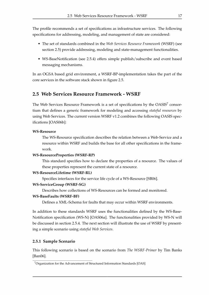
The ShoppingCartService
An online shop wants to offer its clients a Web Service based shopping service. The
user of this service is able to create a shopping cart, add and remove items to the cart
and proceed to the checkout (Figure 2.6). To implement this service, stateful Web Service
Figure 2.6: The ShoppingCartService
technologies are not needed. An implementation with standard Web Services might have
the following interface schema:
Listing 2.1: Porttypes and operation for the CartService with standard Web Services
1 Porttype: WSSimpleShoppingCartCreation
2 Operation: WSCreateCart
3 input
4 output
5 Porttype: WSSimpleShoppingCart
6 Operation: WSCreateCart
7 input
8 output
9 WSCartUnknownFault
10 Operation: WSRemoveItem
11 input
12 output
13 WSCartUnknownFault
14 Operation: WSAddItem
15 input
16 output
17 WSCartUnknownFault
18 Operation: WSGetCart
19 input
20 output
21 WSCartUnknownFault
22 Operation: CartCheckout
23 input
24 output
25 WSCartUnknownFault
26 WSBillingFault
2.5 Web Services Resource Framework - WSRF 19
When creating a cart on the server, the client gets a cartId in the response message to the
create-operation (2.2).
Listing 2.2: WSCreateCartRequest with a non-WSRF service
1 <SOAP-ENV:Header>
2 . . .
3 <wsa:To SOAP-ENV:mustUnderstand="1">
4 http://www.example.com/WSSimpleShoppingService
5 </wsa:To>
6 </SOAP-ENV:Header>
7 <SOAP-ENV:Body>
8 <ws-ssc:WSCreateCartRequest>
9 <ws-ssc:ProductCode>Cat-A2004-87968556</ws-ssc:ProductCode>
10 <ws-ssc:Quantity>1</ws-ssc:Quantity>
11 </ws-ssc:WSCreateCartRequest>
12 </SOAP-ENV:Body>
Listing 2.3: Corresponding “WSCreateCartResponse" to listing 2.2
1 <SOAP-ENV:Body>
2 <ws-ssc:WSCreateCartResponse
3 <ws-ssc:Cart>S1</ws-ssc:Cart>
4 <ws-ssc:ServiceAddress>
5 <wsa:Address>http://example.com/ShoppingService</wsa:Address>
6 </ws-ssc:ServiceAddress>
7 </ws-ssc:WSCreateCartResponse>
8 </SOAP-ENV:Body>
The returned cartId (line 3 in listing 2.3) has to be submitted in every subsequent request
the client makes to the service. This has to be described in a documentation that comes
with the service description and will not be done automatically by the service runtime.
For example, to get the current content of his cart, the client has to include the cartId in
the message-body as shown in the following listing:
1 <ws-ssc:WSGetCart>
2 <ws-ssc:Cart>S1</ws-ssc:Cart>
3 </ws-ssc:WSGetCart>
2.5.2 Keeping State - The concept of a WS-Resource
When designing WSRF, the OASIS consortium tried to avoid the flaws of its predecessor
OGSI8. Instead of extending Web Services with proprietary semantics and functionalities,
WSRF builds on top of the existing W3C Web Services standards9. To design a stateful
service that can be described according to existing W3C standards, the OASIS consortium
designed the construct called WS-Resource.8Open Grid Services Infrastructure [BDP+03]9W3C - World Wide Web Consortium - http://www.w3.org/
20 2 Technological Prerequisites
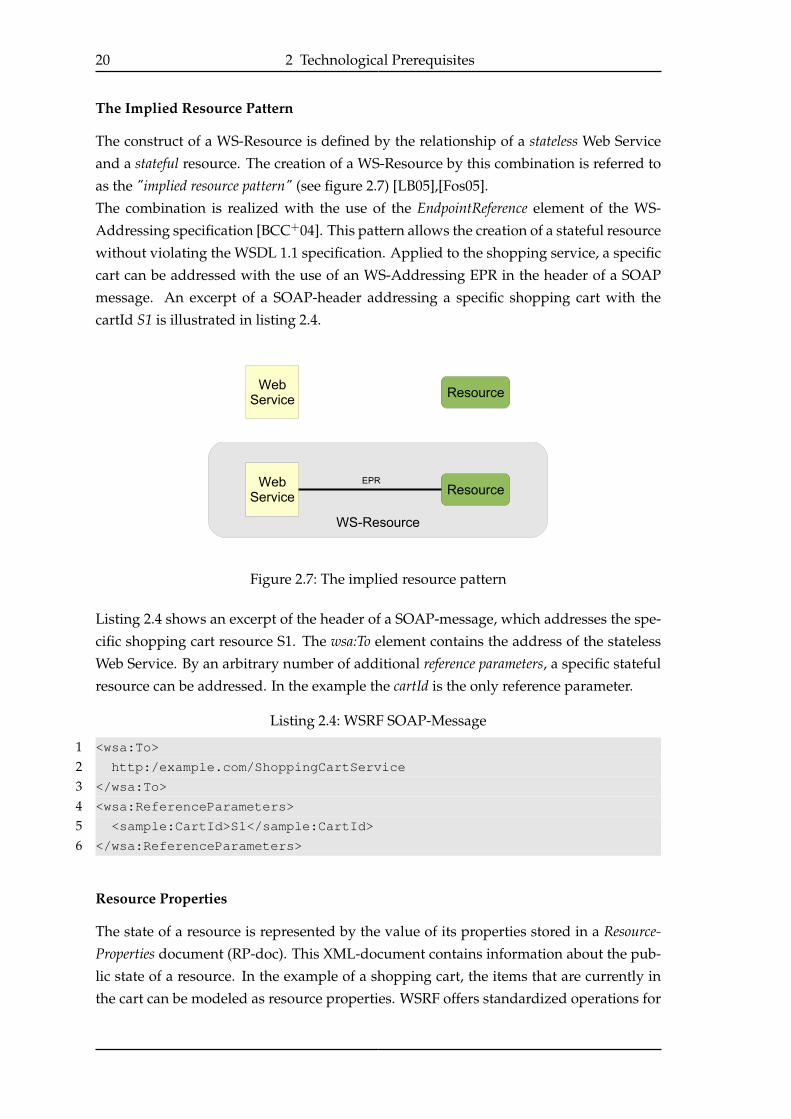
The Implied Resource Pattern
The construct of a WS-Resource is defined by the relationship of a stateless Web Service
and a stateful resource. The creation of a WS-Resource by this combination is referred to
as the "implied resource pattern" (see figure 2.7) [LB05],[Fos05].
The combination is realized with the use of the EndpointReference element of the WS-
Addressing specification [BCC+04]. This pattern allows the creation of a stateful resource
without violating the WSDL 1.1 specification. Applied to the shopping service, a specific
cart can be addressed with the use of an WS-Addressing EPR in the header of a SOAP
message. An excerpt of a SOAP-header addressing a specific shopping cart with the
cartId S1 is illustrated in listing 2.4.
Figure 2.7: The implied resource pattern
Listing 2.4 shows an excerpt of the header of a SOAP-message, which addresses the spe-
cific shopping cart resource S1. The wsa:To element contains the address of the stateless
Web Service. By an arbitrary number of additional reference parameters, a specific stateful
resource can be addressed. In the example the cartId is the only reference parameter.
Listing 2.4: WSRF SOAP-Message
1 <wsa:To>
2 http:/example.com/ShoppingCartService
3 </wsa:To>
4 <wsa:ReferenceParameters>
5 <sample:CartId>S1</sample:CartId>
6 </wsa:ReferenceParameters>
Resource Properties
The state of a resource is represented by the value of its properties stored in a Resource-Properties document (RP-doc). This XML-document contains information about the pub-
lic state of a resource. In the example of a shopping cart, the items that are currently in
the cart can be modeled as resource properties. WSRF offers standardized operations for
2.5 Web Services Resource Framework - WSRF 21
accessing the RP-doc and the contained properties. The action of putting an item into
the shopping cart can be realized as the action of adding an item element to the resource
properties document of the cart WS-Resource. A simple example of a shopping cart with
two items is illustrated by its RP-document in listing 2.5.
Listing 2.5: Content of a shopping cart realized as ResourceProperties
1 <ssc:SimpleShoppingCart>
2 <ssc:Item>
3 <ssc:ProductCode>Cat-A2004-87968556</ssc:ProductCode>
4 <ssc:Description>Garden String - 150m</ssc:Description>
5 <ssc:Quantity>1</ssc:Quantity>
6 <ssc:ProductPrice>1.59</ssc:ProductPrice>
7 </ssc:Item>
8 <scc:Item>
9 <ssc:ProductCode>Cat-A2004-47286265</ssc:ProductCode>
10 <ssc:Description>Garden Rake</ssc:Description>
11 <ssc:Quantity>1</ssc:Quantity>
12 <ssc:ProductPrice>29.59</ssc:ProductPrice>
13 </scc:Item>
14 </ssc:SimpleShoppingCart>
2.5.3 WS-ServiceGroup (WSRF-SG)
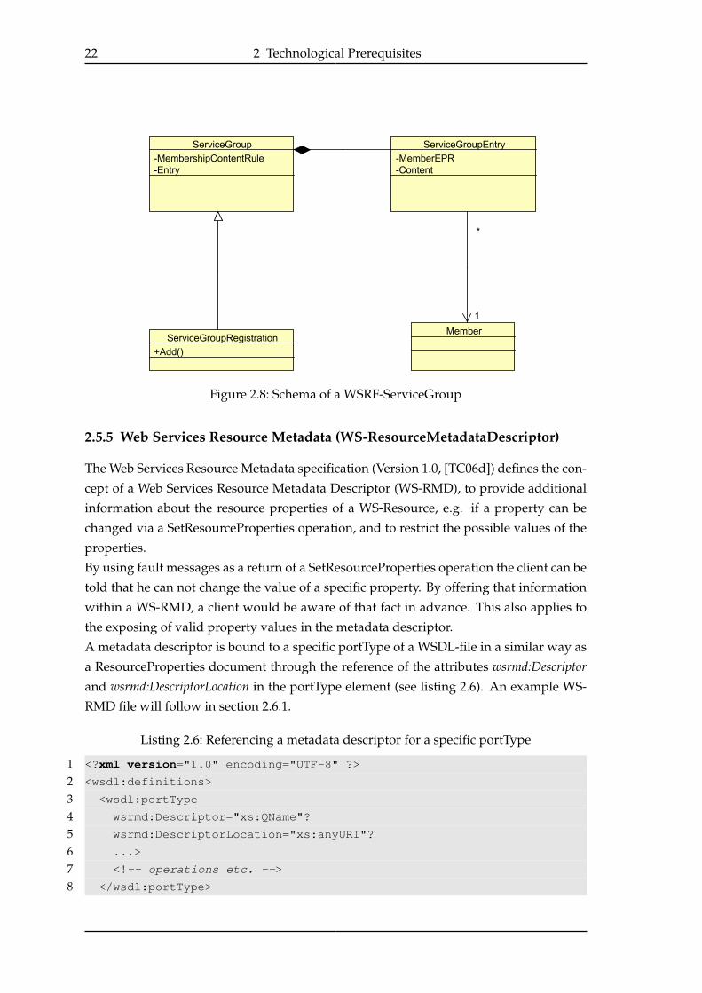
The WSRF documentation specifies a ServiceGroup (SG) as a by-reference collection of WebServices [MSB06]. Services and WS-Resources that are part of the SG are called its Mem-bers. The internal structure of a ServiceGroup is illustrated in figure 2.8. Each member is
associated with a WS-Resource called ServiceGroupEntry. These entry elements represent
the member resources within the ServiceGroup. The ServiceGroupRegistration extends the
SG by offering the add operation as a public interface.
If a WS-Resource is added to a SG an entry resource is created which represents the newly
added member by holding the member’s endpoint reference. A client can retrieve a com-
plete list of all members or query a specific list of members by submitting an XPath query.
Requests to the SG are delegated to its entries and further to the member resources. If a
member is removed from the SG, its specific entry resource will be destroyed.
2.5.4 WS-BaseNotification (WS-BN)
WS-BaseNotification [GHM06] forms the base for the specification family WS-Notification
[OAS06a] (WS-N). WS-Notification also includes WS-Topics and the WS-BrokeredNotfi-
cation specification which allows the use of more complex message exchange patterns.
WS-BaseNotification standardizes interfaces and resources for the use of topic-based Pub-lish/Subscribe communication (section 2.3.2) between Web Services and/or WS-Resources.
22 2 Technological Prerequisites
Figure 2.8: Schema of a WSRF-ServiceGroup
2.5.5 Web Services Resource Metadata (WS-ResourceMetadataDescriptor)
The Web Services Resource Metadata specification (Version 1.0, [TC06d]) defines the con-
cept of a Web Services Resource Metadata Descriptor (WS-RMD), to provide additional
information about the resource properties of a WS-Resource, e.g. if a property can be
changed via a SetResourceProperties operation, and to restrict the possible values of the
properties.
By using fault messages as a return of a SetResourceProperties operation the client can be
told that he can not change the value of a specific property. By offering that information
within a WS-RMD, a client would be aware of that fact in advance. This also applies to
the exposing of valid property values in the metadata descriptor.
A metadata descriptor is bound to a specific portType of a WSDL-file in a similar way as
a ResourceProperties document through the reference of the attributes wsrmd:Descriptorand wsrmd:DescriptorLocation in the portType element (see listing 2.6). An example WS-
RMD file will follow in section 2.6.1.
Listing 2.6: Referencing a metadata descriptor for a specific portType
1 <?xml version="1.0" encoding="UTF-8" ?>
2 <wsdl:definitions>
3 <wsdl:portType
4 wsrmd:Descriptor="xs:QName"?
5 wsrmd:DescriptorLocation="xs:anyURI"?
6 ...>
7 <!-- operations etc. -->
8 </wsdl:portType>

2.6 Web Services Distributed Management (WSDM) 23
9 </wsdl:definitions>
The possibility of defining multiple metadata descriptors within one WS-RMD file makes
the use of two attributes for the reference necessary.
2.6 Web Services Distributed Management (WSDM)
In addition to the WSRF framework, in August 2006 the OASIS consortium defined the
Web Services Distributed Management family of standards, which consists of the spec-
ifications WSDM Management Using Web Services (MUWS) and WSDM Management OfWeb Services (MOWS) [TC06b], [TC06c], [TC06a]. In the following only the concepts and
specifications of WSDM-MUWS are presented, as WSDM MOWS is not relevant for this
thesis.
2.6.1 WSDM-MUWS - Management Using Web Services
WSDM MUWS addresses the manageability of an arbitrary resource with the use of Web
Services. The main focus of WSDM lies on the manageable resource which can be ac-
cessed by a Web Service endpoint and can be configured and monitored by a manage-
ability consumer (see figure 2.9). This concept will now be demonstrated by an example
Figure 2.9: The concept of a manageable resource in WSDM (from [TC06b])
from the MUWS specification [TC06b].
Taking a printer as an example of a resource, it has the central functional aspect of print-
ing, which could be made accessible through a WS-Resource with the use of WSRF and
assuming the printer could be able to indicate its online status and/or toner level: In
WSDM terms these indications form a set of so called manageability capabilities.
MUWS defines an implementation of a manageable resource as a set of manageability capa-bilities offered over a Web Service endpoint.
Manageability Capabilities (from [TC06b])A manageability capability is defined as a capability that
• is uniquely identified in time and environment,

24 2 Technological Prerequisites
• has defined semantics (such as those provided by any section in this specifica-
tion that describes a new capability),
• is associated with a set of properties, operations, events (notifications) and
metadata (including policies).
Composability
The composability concept of WSDM allows a manageable resource implementation to
support a non-conflicting mix of capabilities and Web Services features. Figure 2.10
shows a possible composition of a manageable printer resource implementation.
Figure 2.10: Composability (from [TC06b])
The shown software stack in figure 2.10 consists of two main types of compositions.
1. Composition of Web Services implementation aspectsThe resource implementation can use aspects provided by the Web Services imple-
mentation to enable manageability. These are common functionalities that are not
specially bound to the printer resource. For example, the aspect addressing is cov-
ered by WS-Addressing, properties by WSRF, notifications by WS-Notifications and
the operations are corresponding to operations defined by WSDL.
2. Composition of manageability capabilitiesWSDM distinguishes between common and resource-specific manageability capa-
bilities.
Common manageability capabilities MUWS offers a set of common manageabil-
ity capabilities that can be used for a wide range of resources. For example, it
defines capabilities for the operational state, the caption and description and
relationships to other resources. The only capability a manageable resource
2.6 Web Services Distributed Management (WSDM) 25
has to implement is the identity capability, which inherits the existence of the
muws1:ResourceId within the ResourceProperties document of the resource
(section 2.5).
Resource-specific manageability capabilities Besides the common capabilities, a
resource can implement resource specific capabilities. In the case of a printer,
a toner indication could be such a manageability capability. WSDM is meant
to be a generic specification with which one can define a new resource model,
or which can be used with existing resource models. In the latter case the
existing model can be exposed as an Web service endpoint with the use of
custom manageability capabilities.
Metadata and Metrics
The MUWS specification defines a set of metadata elements that apply to the basic man-
ageability of a manageable resource. Besides general metadata like mutability, modifi-
ability or valid values of properties also specified by WS-RMD, MUWS defines a set of
metadata related to manageability.
Any property element may have a muws2:Units element which can be used to define
the default unit of that property. MUWS defines metadata that allows declaring proper-
ties of a resource as metrics. For example, the printer resource might have the property
PrintedPages, which describes the number of pages that were printed with the current
toner cartridge. The RP-document only defines the element as xsd:int-type with a fixed
occurrence of one. WSDM MUWS allows to add metadata that enriches the definition
with information about gathering time, type of values changes and the period of time the
value of the metric is collected.
Listing 2.7 illustrates the declaration of the property by adding metric-specific metadata
such as the gathering time for the metric, the way its value can change (ChangeType line
14) and the time period for which the metric is valid (TimePeriod). The example uses
WS-RMD (section 2.5.5) to define general and WSDM-specific metadata (The listing only
shows an extract of a metadata descriptor file).
The first step to define a metric is the addition of the Metrics-Capability metadata item
(line 9). A property has to be mutable and not modifiable to be qualified as a metric (as
shown in line 8).
Listing 2.7: Declaration of the property printedPages as a metric by the addition of meta-
data1 <?xml version="1.0" encoding="UTF-8"?>
2 <wsrmd:Definitions
3 xmlns:wsrmd="http://docs.oasis-open.org/wsrf/rmd-1"
4 xmlns:muws2="http://docs.oasis-open.org/wsdm/muws2-2.xsd">
5 <wsrmd:MetadataDescriptor interface="printer:PrinterPortType"
6 name="PrinterMetadata">
26 2 Technological Prerequisites
7 <wsrmd:Property name="PrintedPages"
8 modifiability="read-only" mutability="mutable">
9 <muws2:Capability>
10 http://docs.oasis-open.org/wsdm/muws/capabilities/Metrics
11 </muws2:Capability>
12 <!-- Metric specific metadata -->
13 <muws2:TimeScope>SinceReset</muws2:TimeScope>
14 <muws2:ChangeType>Gauge</muws2:ChangeType>
15 <muws2:GatheringTime>OnChange</muws2:GatheringTime>
16 </wsrmd:Property>
17 </wsrmd:MetadataDescriptor>
18 </wsrmd:Definitions>
The current WSDM specification (Version 1.1) does not define how to apply and where to
define metadata for a manageable resource, but mentions WS-RMD as a possible recom-
mendation in future releases of WSDM. The WSDM MUWS Primer [MWE06] also uses
WS-RMD to describe and expose WSDM metadata.
WSDM Event Format
WSDM defines an XML format to represent management events within a system. Clients
can subscribe to custom events and will be notified via WS-Notification when these
events occur. Common events like the creation of a resource can be broadcast to the
system, which makes a special discovery process for new resources unnecessary.
2.7 Grid Computing in the IT Industry
The term Grid computing is mostly related to the academic driven concept of resource
sharing between organizations. In the IT industry a couple of terms related to Grid com-
puting emerged, which focus on the business driven concepts. Although being com-
parable in the offered features, these business driven terms do not denote the use of a
standardized grid-infrastructure. This means, that most of the offered solutions for e.g.
Utility Computing can not be noted as a Grid computing infrastructure when applying
Foster’s checklist (section 2.4) [FT05].
2.7.1 Utility Computing / Software as a Service / On-demand Computing
The concepts denoted by Utility Computing or Software as a Service (SaaS) overlap signif-
icantly with Grid computing. Grid computing is associated with the idea of accessing
computational power as easy as electricicty. The term utility highlights the offering of the
computational power by a service provider to service consumers, along with specific
Quality of Service (QoS) guarantees.
2.8 Autonomic Computing 27
On-demand computing focuses on the aspect of automatic provisioning of computing re-
sources, if necessary, to meet changing requirements [FT05].
The three business driven concepts share the idea of the two roles of a service provider
and a service consumer. Because of the fact that the offered service is not standardized
but consists of a customized set of applications, the service provider is often also denoted
as Application Service Provider (ASP).
The contract between an ASP and his customers contains information about the intended
behaviour of the offered service or application. The ASP guarantees a specific level ofservice. This agreement is often signed by a so-called Service Level Agreement.
2.7.2 Service Level Agreements
A Service Level Agreement (SLA) is a contract between a service provider and a consumer
which specifies the intended usage of the service by the consumer and the service guar-
antees by the provider. A detailed description of the functionalities of the service is im-
portant to avoid misunderstandings between the parties. According to that the defini-
tion by Strassner specifies a SLA as a “formal negotiated agreement between two parties
designed to create a common understanding about products, services, priorities, respon-
sibilities, and so forth” [Str04].
Besides the common understanding of the service, the specification of the guaranteed Qual-
ity of Service (QoS) is a major aspect of a SLA. These specifications are normally stated
as service level objectives (SLO).
A SLO is a specification of a metric property and a guaranteed level of service for that
metric. Crawford’s et al. definition of a SLA includes the following common metrics for
SLOs [CBC+05]:
• “Performance and capacity (such as end-user response times, business volumes,
throughput rates, system sizing, and utilization levels)
• Availability (mean time between failure for all or parts of the system, disaster re-
covery mechanisms, mean time to recovery, etc.)
• Security (for example, response to systematic attempts to break into a system)”
For example, for the stated metric end-user response time a SLO can be applied like “90%
of all end-user response times have to be shorter than 50 ms”. Obviously, to be effective,
the metrics used for a SLO must be measurable with the used system.
2.8 Autonomic Computing
With the growth in size and matter of functionalities, computing systems are becoming
more and more complex. The management and configuration of such systems require

28 2 Technological Prerequisites
expensive experts. Autonomic Computing (AC) tries to make computing systems more
self-managed and less complex to administer.
2.8.1 Properties of an Autonomic Computing System
Autonomic systems are described as collections of so called autonomic elements (AE).
These autonomic elements and the autonomic system itself have the ability of self-man-
agement, which is described as the combination of self-configuration, self-optimization, self-healing and self-protection [KC03], [HKC+06], [GC03]. According to this definition, auto-
nomic systems are also known as systems with self-star properties [BJM+05].
Self-configurationSelf-configuration describes the ability of a system to execute most of the installa-
tion and configuration tasks automatically following high-level policies.
Self-optimizationA system that offers self-optimization continuously tries to improve its performance
and efficiency.
Self-healingWith self-healing, the ability of a system to detect, diagnose and react automatically
on software and hardware problems is described.
Self-protectionA autonomic system is able to defend itself against network attacks and resulting
failures. This property of a system is called self-protection.
An autonomic element consists of the so called managed element and an autonomic man-ager (AM) (see figure 2.11). The managed element offers sensors and effectors through
standardized management interfaces. The autonomic manager uses these interfaces to
control the element. The management process of the AM is often described by the so
called MAPE-Loop, which stands for the management phases monitor, analyze, plan and
execute. The AM continuously monitors the managed element and writes the monitoring
data to its knowledge base (KB). The received data is evaluated against a defined target
state during the analyze phase. If the current system state is not tolerable, actions are
planned (plan phase) which are executed in the execute phase. How these actions are
derived during the planning phase can be described with service policies.
Autonomic Computing Policies
The upcoming section is mainly based on the article “An Artificial Intelligence Perspec-
tive on Autonomic Computing Policies” by Kephart and Walsh [KW04] and describes
different types of policies that can be used in autonomic computing.
The current state S of a system can be described as a vector of system attributes, which
can be measured directly or indirectly through sensors. Generally a policy defines an
action α which transforms the system from its current state S into a new possible state σ

2.8 Autonomic Computing 29
Figure 2.11: The structure of an autonomic element (from [KC03])
(see figure 2.12).
Kephart and Walsh define a policy as “any type of formal behavioral guide" [KW04] which
purpose is to provide guidance for an autonomic system to choose actions to move it into
desirable states. Three types of policies which could be useful for autonomic computing
are described, the Action, Goal and Utility Function policies. These differ in the way of
how to select an action α, how to define the new possible state σ and how to decide if the
current state S qualifies for a specific policy.
Figure 2.12: System state transitions based on actions α1 - α3 (from [KW04])
Action policies - What should be done?
As the name indicates, action policies define actions that should be executed if a
system is in a given current state. The state (σ) that will be reached by executing
an action is not defined explicitly. The developer of the policy base has to know in
which state the system will be transformed by a specific action α.
Goal policies - Which states are desired?
Goal policies do not define exactly what to do in a specific state, but which states
are desired. Reaching one of these desired states forms the goal of the policy. The
system has to compute a set of actions to transform the system from the current
state S to a desired state σ.
Utility function policies - What objective should be optimized?

30 2 Technological Prerequisites
Instead of classifying states in "desirable" and "undesirable", like goal policies do, a
utility function continuously selects the next desired state as the one with the high-
est utility from the set of possible states.
To use utility functions, a detailed system model is needed. The model must de-
scribe the effects of low-level actions, for being able to identify the actions which
will transform the system to a state with better utility.

31
3 Requirement Specifications
As stated in section 1.2, the CMaaS-team wants to develop a high-performance, scalable
and dynamic email archiving system. This chapter will describe these goals in more de-
tail and analyze the implied requirements for the infrastructure.
The following scenario will illustrate the need of a new archiving solution. It is based
on the high-level goals of the CMaaS project presented in the introduction of this thesis
(section 1.2). It is meant as an exemplary scenario and does not cover all aspects of email
archiving.
3.1 Scenario
SimpleServe is a server-hosting provider and runs a data center which contains servers that
can be rented by its customers. The rented servers can be used by the customers in arbi-
trary ways to satisfy their computing demands (see left part of figure 3.1).
As an additional service, SimpleServe offers a managed email hosting solution. On top
of this simple hosting solution, SimpleServe wants to offer a new Email Archiving and
Management (EAM) service to its customers.
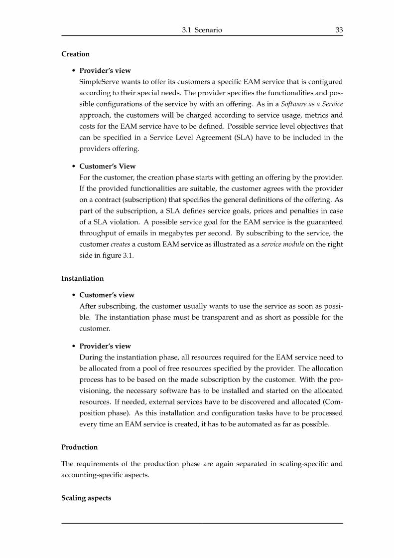
Figure 3.1 shows the change of the business perspective by moving to a Software as a Ser-vice (SaaS) approach. In its current business model, the business objects are the dedicated
servers offered to its customers. By offering an EAM service, the business objects become
abstract, customizable services. The servers on which the EAM service is running are be-
coming transparent to the customers. This change also includes a shift of responsibilities
for the provider. With the old model SimpleServe had to provide the location, electricity
and the hardware itself, while the usage and utilization of the hardware were down to its
customers. Now, aspects like resource utilization, software installation and configuration
as well as the service availability became part of the provider’s responsibility. The next
section describes the features demanded by SimpleServe and its customers for the EAM
service.
3.1.1 Feature Requests for the EAM Service Solution
It is reasonable that SimpleServe has different demands on the EAM system than its cus-
tomers. The customers are only interested in the offered service functionalities and how
they can configure and use the service. The provider needs a way to offer the EAM ser-
vice with its existing resources. Due to this fact, the feature requests are separated into
two different views, the Provider’s view (SimpleServe) and the Customer’s view (service
consumers).
32 3 Requirement Specifications
Figure 3.1: Comparison of business objects for the dedicated server and EAM servicebusiness models.
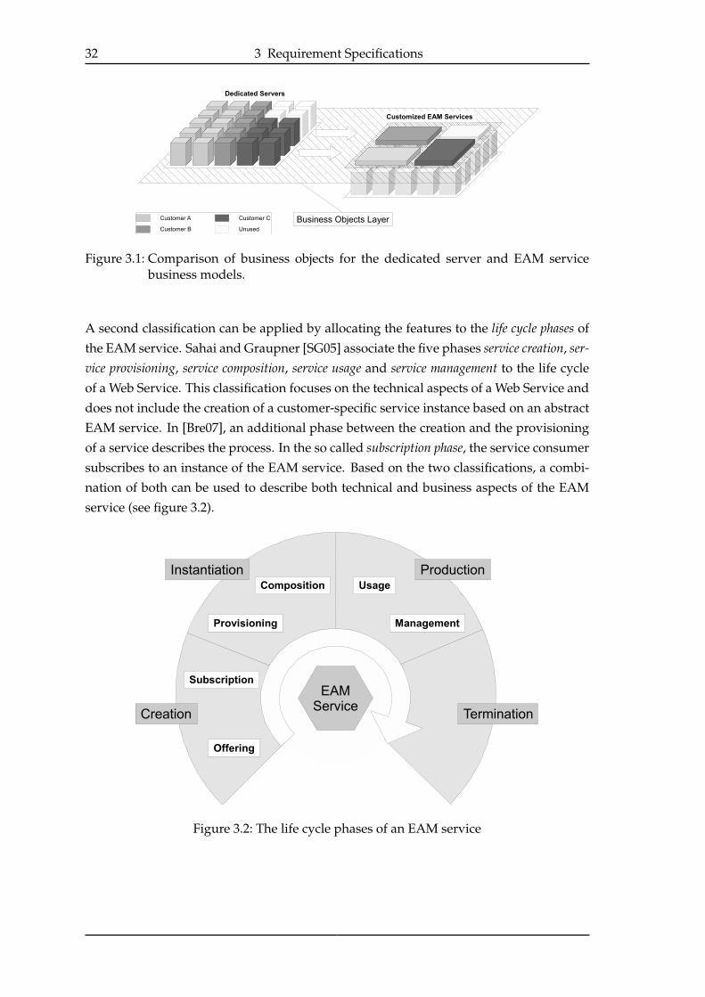
A second classification can be applied by allocating the features to the life cycle phases of
the EAM service. Sahai and Graupner [SG05] associate the five phases service creation, ser-vice provisioning, service composition, service usage and service management to the life cycle
of a Web Service. This classification focuses on the technical aspects of a Web Service and
does not include the creation of a customer-specific service instance based on an abstract
EAM service. In [Bre07], an additional phase between the creation and the provisioning
of a service describes the process. In the so called subscription phase, the service consumer
subscribes to an instance of the EAM service. Based on the two classifications, a combi-
nation of both can be used to describe both technical and business aspects of the EAM
service (see figure 3.2).
Figure 3.2: The life cycle phases of an EAM service
3.1 Scenario 33
Creation
• Provider’s viewSimpleServe wants to offer its customers a specific EAM service that is configured
according to their special needs. The provider specifies the functionalities and pos-
sible configurations of the service by with an offering. As in a Software as a Serviceapproach, the customers will be charged according to service usage, metrics and
costs for the EAM service have to be defined. Possible service level objectives that
can be specified in a Service Level Agreement (SLA) have to be included in the
providers offering.
• Customer’s ViewFor the customer, the creation phase starts with getting an offering by the provider.
If the provided functionalities are suitable, the customer agrees with the provider
on a contract (subscription) that specifies the general definitions of the offering. As
part of the subscription, a SLA defines service goals, prices and penalties in case
of a SLA violation. A possible service goal for the EAM service is the guaranteed
throughput of emails in megabytes per second. By subscribing to the service, the
customer creates a custom EAM service as illustrated as a service module on the right
side in figure 3.1.
Instantiation
• Customer’s viewAfter subscribing, the customer usually wants to use the service as soon as possi-
ble. The instantiation phase must be transparent and as short as possible for the
customer.
• Provider’s viewDuring the instantiation phase, all resources required for the EAM service need to
be allocated from a pool of free resources specified by the provider. The allocation
process has to be based on the made subscription by the customer. With the pro-
visioning, the necessary software has to be installed and started on the allocated
resources. If needed, external services have to be discovered and allocated (Com-
position phase). As this installation and configuration tasks have to be processed
every time an EAM service is created, it has to be automated as far as possible.
Production
The requirements of the production phase are again separated in scaling-specific and
accounting-specific aspects.
Scaling aspects
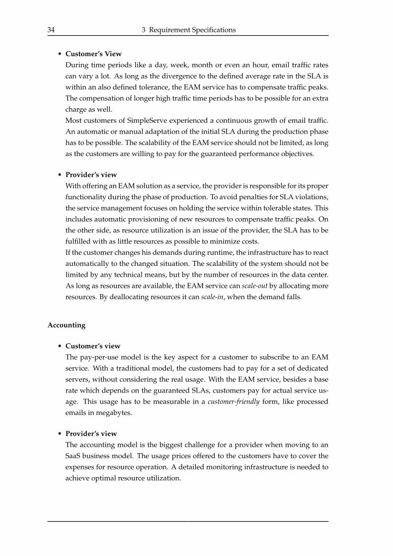
34 3 Requirement Specifications
• Customer’s ViewDuring time periods like a day, week, month or even an hour, email traffic rates
can vary a lot. As long as the divergence to the defined average rate in the SLA is
within an also defined tolerance, the EAM service has to compensate traffic peaks.
The compensation of longer high traffic time periods has to be possible for an extra
charge as well.
Most customers of SimpleServe experienced a continuous growth of email traffic.
An automatic or manual adaptation of the initial SLA during the production phase
has to be possible. The scalability of the EAM service should not be limited, as long
as the customers are willing to pay for the guaranteed performance objectives.
• Provider’s viewWith offering an EAM solution as a service, the provider is responsible for its proper
functionality during the phase of production. To avoid penalties for SLA violations,
the service management focuses on holding the service within tolerable states. This
includes automatic provisioning of new resources to compensate traffic peaks. On
the other side, as resource utilization is an issue of the provider, the SLA has to be
fulfilled with as little resources as possible to minimize costs.
If the customer changes his demands during runtime, the infrastructure has to react
automatically to the changed situation. The scalability of the system should not be
limited by any technical means, but by the number of resources in the data center.
As long as resources are available, the EAM service can scale-out by allocating more
resources. By deallocating resources it can scale-in, when the demand falls.
Accounting
• Customer’s viewThe pay-per-use model is the key aspect for a customer to subscribe to an EAM
service. With a traditional model, the customers had to pay for a set of dedicated
servers, without considering the real usage. With the EAM service, besides a base
rate which depends on the guaranteed SLAs, customers pay for actual service us-
age. This usage has to be measurable in a customer-friendly form, like processed
emails in megabytes.
• Provider’s viewThe accounting model is the biggest challenge for a provider when moving to an
SaaS business model. The usage prices offered to the customers have to cover the
expenses for resource operation. A detailed monitoring infrastructure is needed to
achieve optimal resource utilization.

3.2 The CMaaS Approach 35
Termination
• Customer’s viewIf the customer has no need for the EAM service any longer, he can just unsubscribe
from it. From that point onwards, no costs are generated for his account.
• Provider’s viewIf a customer quits a subscription to the EAM service, the used resources have to be
deallocated and made available for later usage.
3.2 The CMaaS Approach
The above-mentioned scenario illustrated the intended usage of the EAM system seen
from the perspective of a service consumer and a service provider. While for the con-
sumer the usage of the system gets a lot easier than using its own EAM installation, a
lot of questions arise for the service provider. A suitable infrastructure is needed, which
supports the provider during all phases of the service runtime (see figure 3.2).
Two main aspects of the needed EAM system are performance and scalability. As the sys-
tem should scale with the demands of the customers, it needs to be capable of processing
an almost arbitrary amount of emails, as long as enough hardware for usage is available
and the customer is willing to pay for that performance. With the cmgrid-prototype (see
section 1.2.3), the CMaaS team in Stuttgart tries to cope with the aspects of scalability and
performance [WMM+07].
3.2.1 Applying Service-Orientation to the EAM System
With the beginning of this thesis (9/2006), the CMaaS team in Hamburg faces the aspects
of service-orientation and management automation. Generally, a service-oriented archi-
tecture (SOA) promises the advantages of location transparency and service composition
(section 2.3.1). The thesis “Componentization and Orchestration of Content Management
Services” [Biß07] analyzes, how service orientation can be applied to an EAM system.
With applying the theoretical concept to the cmgrid prototype, the impact of the approach
to the reached overall performance is measured.
A Service-Oriented EAM system
In a service-oriented architecture the atomic element is the service. This indicates that all
components of the EAM system have to be transformed into or encapsulated by a ser-
vice. One of the possible service-oriented designs is shown in figure 3.3. All included
services are part of a scalable service pool. Besides the mainly static components Work-load Manager and Registry, a set of Content Management services (CM services) is present in
the service pool. The abstract term CM service was chosen, as the actual implementations

36 3 Requirement Specifications
can vary in service granularity. The design possibilities of the CM services are discussed
in detail in [Biß07]. As an example, a CM Service could be responsible for the complete
ingest process (see use cases in section 1.2.2) or only for parts like indexing, parsing or
archiving of an email document.
The second main component of the system is the Content Repository. In this design it is a
logical component that is combined from a distributed catalog, implemented as full-textsearch indices, and an Archive which is responsible for the actual archiving of the origi-
nal email documents. The Repository Interface offers an integrated access to the content
repository, without requiring knowledge about the distributed approach.
Figure 3.3: A service-oriented design for the EAM system
The arrows in figure 3.3 indicate the communication between the system components
during the ingest process. In the example, a CM service is responsible for all tasks during
the ingest process. A simplified workflow for the ingest process is executed as follows.
The Workload Manager continuously monitors the email server(s) for new incoming or
outgoing emails (1). If new emails are sensed, an archiving job is created that can be
processed by a CM service. The Workload Manager requests the Registry for available
CM services (2) and passes the generated archiving job to a specific CM service that is
most suitable, due to the internal workload management algorithm (3). During the actual
content management work, the CM service gets the mail document from the email server
(4), generates the search index and passes the original email to the Archive (5).
For a detailed description of the internal process within the CM services, the reader is
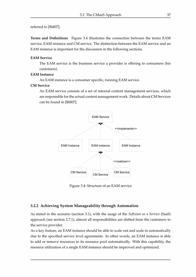
3.2 The CMaaS Approach 37
referred to [Biß07].
Terms and Definitions Figure 3.4 illustrates the connection between the terms EAM
service, EAM instance and CM service. The distinction between the EAM service and an
EAM instance is important for the discussion in the following sections.
EAM ServiceThe EAM service is the business service a provider is offering to consumers (his
customers).
EAM InstanceAn EAM instance is a consumer specific, running EAM service.
CM ServiceAn EAM service consists of a set of internal content management services, which
are responsible for the actual content management work. Details about CM Services
can be found in [Biß07].
Figure 3.4: Structure of an EAM service
3.2.2 Achieving System Manageability through Automation
As stated in the scenario (section 3.1), with the usage of the Software as a Service (SaaS)
approach (see section 2.7.1), almost all responsibilities are shifted from the customers to
the service provider.
As a key feature, an EAM instance should be able to scale out and scale in automatically
due to the specified service level agreements. In other words, an EAM instance is able
to add or remove resources to its resource pool automatically. With this capability, the
resource utilization of a single EAM instance should be improved and optimized.
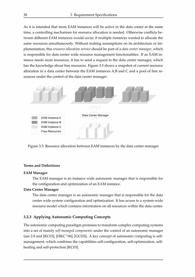
38 3 Requirement Specifications
As it is intended that more EAM instances will be active in the data center at the same
time, a controlling mechanism for resource allocation is needed. Otherwise conflicts be-
tween different EAM instances would occur, if multiple instances wanted to allocate the
same resources simultaneously. Without making assumptions on its architecture or im-
plementation, this resource allocation service should be part of a data center manager, which
is responsible for data center wide resource management functionalities. If an EAM in-
stance needs more resources, it has to send a request to the data center manager, which
has the knowledge about free resources. Figure 3.5 shows a snapshot of current resource
allocation in a data center between the EAM instances A,B and C and a pool of free re-
sources under the control of the data center manager.
Figure 3.5: Resource allocation between EAM instances by the data center manager
Terms and Definitions
EAM ManagerThe EAM manager is an instance wide autonomic manager that is responsible for
the configuration and optimization of an EAM instance.
Data Center ManagerThe data center manager is an autonomic manager that is responsible for the data
center wide system configuration and optimization. It has access to a system-wide
resource model which contains information on all resources within the data center.
3.2.3 Applying Autonomic Computing Concepts
The autonomic computing paradigm promises to transform complex computing systems
into a set of mainly self-managed components under the control of an autonomic manager
(see 2.8 and [KC03], [HKC+06], [GC03]). A key concept of autonomic computing is self-
management, which combines the capabilities self-configuration, self-optimization, self-
healing and self-protection [KC03].

3.2 The CMaaS Approach 39
The high-level requirements described in the scenario can be mapped to these self-* prop-erties. In this thesis the properties self-configuration, self-optimization, self-healing and
self-protection are used to classify the autonomic requirements.
Self-configuration
An autonomic EAM service will be installed and configured on demand. If a customer
decides to subscribe to the service and all informations needed are given, the system
allocates the necessary hardware from the resource pool, installs operating systems and
applications. The internal services will automatically connect to the service registry after
instantiation. In other words, all actions that are taken between a subscription and the
first service usage have to be automated.
Self-optimization
With current EAM systems running on rented, dedicated servers, the system utilization
is down to the customer. By introducing the “pay per use” concept and service level
agreements, the need of better system utilization is critical for the service provider.
To approach this problem, the EAM service should be able to scale-out (allocation of new
resources, see Use Case 1, figure 3.6) and scale-in (return of idle resources, see Use Case
2, figure 3.7) automatically, due to current system utilization and according to the agreed
service level objectives. In the use cases, the existence of a Resource Management System(RMS) that is responsible for the allocation of free resources is assumed.
Besides this coarse-grained scaling based on hardware resources, optimization based on
internal service-configurations should be supported, too. Different types of content de-
mand different service configurations. The possibility to assign resources independently
- e.g. for parsing, archiving and indexing components during runtime - could increase
overall system performance. The infrastructure should provide control mechanisms that
allow such fine-grained optimizations.
Self-healing and Self-protection
The self-healing and self-protection capabilities needed for an EAM system especially
assign the content, that is archived. At any time, the archived data must be accessi-
ble. Hardware failures such as hard disk or complete server crashes have to be compen-
sated. The mechanisms also enable hardware maintenance during the production phase,
as servers can be disconnected from the system without influencing its processing.
3.2.4 The Vision of an Autonomic, Service-Oriented Email Archiving System
When applying general autonomic computing concepts (section 2.8) to the EAM service,
the data center (or the part that is reserved for the EAM service) becomes an autonomic
system with the EAM instances and the data center manager as the autonomic elements.

40 3 Requirement Specifications
Use Case 1 - System scale-out
Description The number of resources allocated to the EAM service is increased.
Actors Resource Management Service (RMS), CM service
Rationale The application manager detects or predicts an SLA-violation byfalling below the guaranteed throughput level and orders the RMSto add a server with “N” CM services to the application pool.
Preconditions The data-center contains idle resources that can be used for the EAMservice.
Normalflow
1. The RMS removes a server from the pool of free servers and addsit to the EAM service model.
2. The RMS installs the needed software on the server.
3. “N" CM services are deployed and instantiated.
4. The CM services process their internal startup actions and addthemselves to the Registry.
5. Upon completion, the CM services set their status to “available”.
Postconditions A new server with the requested number of services was added tothe application-pool
Figure 3.6: Use Case 1 - System scale-out
Figure 3.8 shows a high-level model of an autonomic and dynamic email archiving sys-
tem by applying the described SOA and autonomy concepts to the design from figure
3.3.
The figure shows a service pool, which contains both static and dynamic services from
figure 3.3. The EAM instance manager controls and optimizes the internal CM services.
The email ingest is processed equally to the process in figure 3.3 and is omitted in this
figure.
The autonomic manager continuously gets data from the sensors of the EAM instance,
which could be collected instance-wide by a monitoring service. Due to the specific SLAs,
the manager propagates management actions to the specific services or the resource man-
agement system. The RMS should include a provisioning service, which can be used to
scale the service pool by changing hardware allocations and service instantiations. This
high-level view shows the intended behaviour of the system, but does not make any
assumptions on the overall architecture of the EAM service.
3.3 The Building Blocks of the EAMS Infrastructure
The high-level design of the autonomic EAM system in figure 3.8 motivates three buildingblocks for the EAM system.
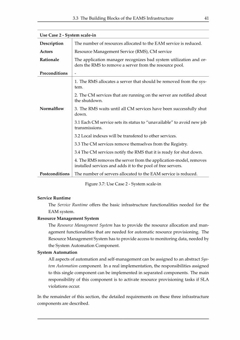
3.3 The Building Blocks of the EAMS Infrastructure 41
Use Case 2 - System scale-in
Description The number of resources allocated to the EAM service is reduced.
Actors Resource Management Service (RMS), CM service
Rationale The application manager recognizes bad system utilization and or-ders the RMS to remove a server from the resource pool.
Preconditions -
Normalflow
1. The RMS allocates a server that should be removed from the sys-tem.
2. The CM services that are running on the server are notified aboutthe shutdown.
3. The RMS waits until all CM services have been successfully shutdown.
3.1 Each CM service sets its status to “unavailable” to avoid new jobtransmissions.
3.2 Local indexes will be transfered to other services.
3.3 The CM services remove themselves from the Registry.
3.4 The CM services notify the RMS that it is ready for shut down.
4. The RMS removes the server from the application-model, removesinstalled services and adds it to the pool of free servers.
Postconditions The number of servers allocated to the EAM service is reduced.
Figure 3.7: Use Case 2 - System scale-in
Service RuntimeThe Service Runtime offers the basic infrastructure functionalities needed for the
EAM system.
Resource Management SystemThe Resource Management System has to provide the resource allocation and man-
agement functionalities that are needed for automatic resource provisioning. The
Resource Management System has to provide access to monitoring data, needed by
the System Automation Component.
System AutomationAll aspects of automation and self-management can be assigned to an abstract Sys-tem Automation component. In a real implementation, the responsibilities assigned
to this single component can be implemented in separated components. The main
responsibility of this component is to activate resource provisioning tasks if SLA
violations occur.
In the remainder of this section, the detailed requirements on these three infrastructure
components are described.

42 3 Requirement Specifications
Figure 3.8: Concept of an autonomic email archiving and management system
3.3.1 Service Runtime
The service runtime provides the basic functionalities for the service oriented EAM sys-
tem. As the intended architecture for the EAM service is a SOA, all system components
have to be at least accessible through interfaces provided by the service runtime [NL04].
The essential requirements can be categorized into two groups. The first are the function-
alities needed for implementing the design concepts developed by Malte Biß in [Biß07].
Secondly, the Resource Management System and the System Automation components require
specific functionalities.
Design-Specific Requirements
It must be at least possible to implement all services from the service-oriented design
shown in figure 3.3 on page 36.
RegistryThe registry has to offer at least classical directory service functionalities as all CM
services has to be discoverable. An idea for simple workload management is that
the registry also has access to state information of its entries [Biß07]. This require-
ment goes further than classical registry functionalities, but would allow comfortable
access to services.
Workload Manager

3.3 The Building Blocks of the EAMS Infrastructure 43
No specific requirements are demanded by the Workload Manager service. The gen-
eral requirements needed for general system management are presented in the In-frastructure requirements section.
Content Management ServicesAs stated before, the CM services are the ones actually responsible for Content
Management tasks. The different granularity designs for CM services, discussed
in [Biß07], have to be realizable with the selected runtime. For testing purposes, an
easy adjusting of granularity at deployment time should be provided.
One of the reasons a service-oriented concept was chosen is the ability of recon-
figuring the system during runtime. Figure 3.9 illustrates how the EAM system
can be reconfigured. Based on resource utilization, additional CM services can be
started, as shown on two nodes on the right side of the figure. Later these services
can be shut down, if they take up too much system resources. These service-based
Figure 3.9: Service based system reconfiguration
reconfiguration steps imply that services can be started, stopped and destroyed if
necessary. In other words, the services need to be aware of their state and in this
case their current state in the service life-cycle. These state-aware services are often
called stateful services.
Infrastructure Requirements
Seeing the service runtime in the context of an autonomic system, the runtime services are
becoming the manageable elements that are controlled by an autonomic manager. With-
out considering the autonomic manager itself, to become manageable, external interfaces
for monitoring and management access are needed [WHW+04]. These interfaces are of-
ten called the sensors and effectors of a manageable element [KC03]. The EAM-specific
requirements for the effectors and sensors are discussed next.
Monitoring Interfaces - SensorsTo optimize the configuration of an EAM instance and to keep it within defined ser-
vice level objectives, an autonomic manager needs access to the state information
of a CM service. When examining the coarse grained CM service referred to as PAI

44 3 Requirement Specifications
service1, which includes all tasks of the ingest process, state information like the size
and location of the index, the number of processed emails or the current working
status are needed to get a view of the current state of the EAM system.
To offer practical service-based monitoring, besides classical polling of needed in-
formation, the runtime should offer some kind of publish/subscribe mechanism to
minimize message exchanges.
Management Interfaces - EffectorsThe management interfaces of a manageable element are the interfaces which al-
low to change the configuration or state of an element. In case of the CM services
these include all configuration options that can influence the content management
process.
3.3.2 Resource Management
The Resource Management System (RMS) should offer a kind of abstraction layer on top
of the used computing hardware. The three main responsibilities are the management
of resource allocation, the provisioning service, which automates software installations,
and the offering of detailed monitoring data.
Provisioning Service
When a customer subscribes to the EAM service, a new instance has to be created. A
set of hardware resources will be allocated for the instance (see next section) that have
to be set up for the EAM service. In a real-world scenario, the data center of the service
provider would not be used exclusively for the EAM service, but for a collection of SaaS
applications. Though unused resources can be assigned to different kinds of services,
which e.g. have different requirements for the operating system or application servers.
The provisioning service must be able to install a specific server configuration on a cleanserver.
Resource Allocation
As illustrated in section 3.2.2, the data center manager or even a manual management com-
ponent need to be aware of the current resource usage in the data center. A common way
to model resource allocations is by the use of a hierarchical resource model.
Resource Model
A Resource Model illustrates allocations with simple “belongs to” relations. In [SCD+97]
three different perspectives on Quality of Service (QoS) driven resource management are
1PAI stands for parsing, archiving and indexing of an email. Indeed a PAI service is responsible for allother content management tasks, too.

3.3 The Building Blocks of the EAMS Infrastructure 45
introduced, the Application, Resource and System perspective. These perspectives are used
for the hierarchical layers of an exemplary, simplified resource model in figure 3.10. On
Figure 3.10: The three perspectives of resource management
top of the hierarchy in the system perspective, the RMS itself works to manage all re-
sources of the data center. The application layer contains virtual elements, which repre-
sent e.g. EAM instances or the pool of free resources. Elements in the resource layer rep-
resent real hardware or software resources of the data center. Each element is associated
with an element of the application layer, to model its current allocation. If a free resource
is allocated to an EAM instance, the representing element in the model is “moved” to the
EAM instance by changing the association from the “free resources” element to the spe-
cific EAM instance element. Within the resource perspective, more associations, which
illustrate the installed software components or services on a hardware resource are pos-
sible. When deallocating a resource, the system knows which applications have to be
removed.
The use of a resource model indicates that all changes of the infrastructure must be syn-
chronized with the RMS system to avoid inconsistent resource models.
Required Monitoring Functionalities
The System Automation component needs detailed monitoring data to keep an EAM in-
stance within the area of the guaranteed service level objectives. For this, monitoring
data from the resource and the application layer are needed. As higher-level elements
of the resource model are aggregations of lower-level elements, metrics of the applica-
tion layer are aggregated from resource perspective metrics. This mapping is critical for
the SLA management, as service level objectives are formulated with application-wide
metrics (see section 2.7.2). To enable the optimization of resource utilization, low-level
monitoring data like CPU-utilization, memory usage or disk-capacity are needed. In the
following, the requirements on the offered metrics will be discussed.
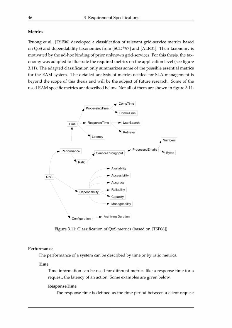
46 3 Requirement Specifications
Metrics
Truong et al. [TSF06] developed a classification of relevant grid-service metrics based
on QoS and dependability taxonomies from [SCD+97] and [ALR01]. Their taxonomy is
motivated by the ad-hoc binding of prior unknown grid-services. For this thesis, the tax-
onomy was adapted to illustrate the required metrics on the application level (see figure
3.11). The adapted classification only summarizes some of the possible essential metrics
for the EAM system. The detailed analysis of metrics needed for SLA-management is
beyond the scope of this thesis and will be the subject of future research. Some of the
used EAM specific metrics are described below. Not all of them are shown in figure 3.11.
Figure 3.11: Classification of QoS metrics (based on [TSF06])
PerformanceThe performance of a system can be described by time or by ratio metrics.
TimeTime information can be used for different metrics like a response time for a
request, the latency of an action. Some examples are given below.
ResponseTimeThe response time is defined as the time period between a client-request
3.3 The Building Blocks of the EAMS Infrastructure 47
and the time the client receives the response. For the EAM service re-
sponse times could be defined for regular search, manual archiving or emailretrieval requests.
Latency - TimeToFindableThe TimeToFindable metric defines the time period from the beginning of
an ingest request (automatic or manual) to the time the ingested document
can be found in the system.
Ratio - ServiceThroughputIn "classical" Web Services, the throughput of a service is defined as the num-
ber of processed requests over a period of time. As the EAM service offers
different services, separate throughput metrics must be defined.
ArchivingThroughputThe archiving throughput defines the amount of data (in bytes) the service
was able to archive in a period of time. Throughput-rates for different time
periods should be accessible.
SearchThroughputThe search throughput defines the ratio of regular search requests per time
period (see use case in section 1.2.2).
RetrievalThroughputThe retrieval throughput describes the amount of documents (as data in
bytes) per time period that can be retrieved from the archive.
DependabilityThe dependability category contains metrics, which depend on other metrics or a
set of metrics. For this example, the functionalities required by the workload man-
agement component are divided into the two components Dispatcher and Crawler.
More about this componentization can be found in [Biß07].
AvailabilityAvailability is defined by the equation Availability = UpTime
PeriodOfT ime [TSF06],
where UpTime is the part of time in PeriodOfT ime in which the service has
been available. A service is available when it is ready for immediate use2.
By having a complex system instead of a “simple” Web Service, the availabil-
ity of the EAM service depends on the availability of its internal components
(see figure 3.12). An EAM service is available for archiving, if all static ser-
vices (Dispatcher, Registry, Crawler) and at least one CM service of each category
needed (in the simple example just one PAI service) is available. The availabil-
ity of the internal services itself depend on the availability of the hardware
resources they are running on (not shown in the figure). Nevertheless an EAM
service could be available for a retrieval request if the Crawler and Dispatcher
are unavailable, as long as all retrieval-related services are available.
2From http://www-128.ibm.com/developerworks/library/ws-quality.html - last visited on 04/17/2007

48 3 Requirement Specifications
Figure 3.12: Dependencies of application-wide availability on the internal resources
ReliabilityReliability describes the capability of delivering correct service. The reliabil-
ity of a system is often described through its “mean time between failures”
(MTBF) [TSF06]. Application-wide reliability depends on the reliability of
each CM Service.
3.3.3 System Automation
The System Automation component has to execute management tasks, which are normally
handled manually. One approach for system automation is the autonomic computing
concept (see section 2.8). Having discussed which tasks have to be automated in section
3.2.3, this section will describe an autonomic computing architecture, that could be used
for the EAM system.
An Autonomic Architecture for the EAM System
How autonomic elements can be arranged to form a production system, is the key issue
of the IBM whitepaper “An architectural blueprint for autonomic computing” [IBM06]. It sug-
gests the components manageability endpoints3, autonomic managers (AM), knowledge
sources and manual managers as the building blocks of autonomic computing. These
components can be composed to form self-managed systems.
Figure 3.13 illustrates a “generic hierarchical arrangement of autonomic and manual
managers” [IBM06], which form a topology of the building blocks.
The bottom layer consists of the managed resources (MR), which can consist of servers,
storage components or applications. The resources itself could contain some self-man-
agement capabilities, illustrated by the autonomic control loop. Layer two standardizes the
access to the MRs by applying manageability endpoint implementations to each resource.
By this approach the general management access to a database or to an application is
3Also called touchpoints

3.3 The Building Blocks of the EAMS Infrastructure 49
Figure 3.13: Autonomic computing reference architecture [IBM06]
nearly the same and only differ by the specific endpoint implementation.
Each resource can be controlled by an AM, which uses the resource-specific manage-
ability endpoint to realize self-management capabilities. These autonomic managers are
orchestrated by AMs in the layer above. These orchestrating AMs differ in their perspec-
tives on the system and self-management capabilities and offer system-wide autonomic
capabilities by incorporating lower level control loops. On top of all layers, a manual
manager can configure the system by accessing the manageability endpoints of the or-
chestrating AMs through some kind of control console. All layers have access to a set of
knowledge sources which enable knowledge sharing between different AMs
Another key component of the architecture is the Enterprise Service Bus (ESB), which acts
as a glue between all other components. The term Enterprise Service Bus is frequently
used in business products4. The basic responsibilities commonly assigned to an ESB cor-
respond with the classical responsibilities of a service runtime.
For this thesis, the presented architecture was mapped onto the EAM system. The adapt-
ed version of the architecture is illustrated in figure 3.14. This architecture separates the
hierarchical layers in vertical containers depending on their association with an EAM in-
stance. The knowledge sources (omitted in figure 3.14), which were shared between and
accessible by all layers and AMs, now have to offer different views on the data for every
EAM instance and a complete view for the data center management components. The
layer of managed resources consists of actual hardware resources like servers and e.g.
the CM Services which can all be handled independently as a manageable element. To
4e.g. Oracle® Enterprise Service Bus, IBM WebSphere Enterprise Service Bus
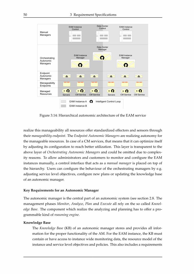
50 3 Requirement Specifications
Figure 3.14: Hierarchical autonomic architecture of the EAM service
realize this manageability all resources offer standardized effectors and sensors through
their manageability endpoint. The Endpoint Autonomic Managers are realizing autonomy for
the manageable resources. In case of a CM services, that means that it can optimize itself
by adjusting its configuration to reach better utilization. This layer is transparent to the
above layer of Orchestrating Autonomic Managers and could be omitted due to complex-
ity reasons. To allow administrators and customers to monitor and configure the EAM
instances manually, a control interface that acts as a manual manager is placed on top of
the hierarchy. Users can configure the behaviour of the orchestrating managers by e.g.
adjusting service level objectives, configure new plans or updating the knowledge base
of an autonomic manager.
Key Requirements for an Autonomic Manager
The autonomic manager is the central part of an autonomic system (see section 2.8. The
management phases Monitor, Analyze, Plan and Execute all rely on the so called Knowl-edge Base. The component which realize the analyzing and planning has to offer a pro-
grammable kind of reasoning engine.
Knowledge BaseThe Knowledge Base (KB) of an autonomic manager stores and provides all infor-
mation for the proper functionality of the AM. For the EAM instance, the KB must
contain or have access to instance wide monitoring data, the resource model of the
instance and service level objectives and policies. This also includes a requirements
3.4 Summary 51
on the resource management system, that monitoring metrics have to be compati-
ble to the metrics used for the service level objectives and policies. Generally, the
expression of information in a machine-readable form is essential for the usability
of the KB.
Reasoning EngineThe reasoning engine of an AM is responsible for the proper reactions of the system
in case of SLA violations. In section 2.8 three different types of service policies
were introduced, action, goal and utility function policies. Action policies are the
simplest form of policies and rely on a deep knowledge of system behaviour.
3.4 Summary
The requirements for a service oriented, automated EAM system are complex and nu-
merous. For this thesis, these requirements were classified into the three categories Ser-vice Runtime, Resource Management and System Automation. As the base for the complete
system, the service runtime has to offer manageable services, that can provide state in-
formation about the applications or resources they represent in a standardized way. The
Resource Management System has to offer resource allocation and provisioning functionali-
ties. By providing EAM instance specific perspectives on the resource model, services can
get access to available resources within an EAM instance. Application based monitoring
data has to be combined with low-level information like CPU and memory usage to al-
low the optimization of resource utilization. The System Automation category combines
requirements that are needed, to transform the EAM system into an autonomic system.
System automation requires the manageability of the used services and resources. The
formulation of service level objectives and service policies in a machine-readable and in-
terpretable form is the major requirement and challenge for a successful implementation.
More detailed research has to be done in this sector to formulate the actual service goals
and effects of planned actions to the system.

52 3 Requirement Specifications
53
4 Service Runtime Evaluation
This part of the evaluation focuses on the required service runtime for the EAM system,
presented in chapter 3.
4.1 The WSRF Basic Profile Specification
When designing a SOA, the use of open standards for service accessibility is critical (SOAPrincipals and guidelines in [NL04]). Web Services are a common way to implement a SOA,
although with the lack of state, traditional web service technologies are not adequate as
the intended infrastructure. By the usage of proprietary semantics and functions, the
state awareness of traditional Web Services can be achieved, but this destroys the benefit
of open standards.
The Open Grid Service Architecture (OGSA, section 2.4.2) can be seen as the de facto stan-
dard for Grid computing. In an OGSA-based grid, every resource is based on a grid
/ infrastructure service. The recommended service infrastructure is the Web Services
Resource Framework (WSRF, see 2.5). It defines how to access and populate arbitrary
resources through the use of Web Services technology. In 2006 the OGF1 announced the
OGSA WSRF Basic Profile 1.0, to accomplish basic interoperability between OGSA imple-
mentations. According to this, the service runtime layer in an OGSA based grid should
be exchangeable as long as it is compatible to the WSRF Basic Profile.
Other parts of OGSA are not fully standardized or even fully specified, which makes
the Basic Profile a good base for the service runtime of the intended EAM service. After
a short discussion about XML processing in enterprise environments, the WSRF Basic
Profile will be compared to the requirements defined in section 3.3.1.
4.1.1 XML Processing in the Enterprise
XML- and especially SOAP-based communication entails messaging overhead by mes-
sage size and processing time, which kept many businesses from using XML in enterprise
applications.
Chen et al. showed that "SOAP is a compelling protocol to its binary alternatives for small mes-sages" [CYZ+06]. The intended usage of the service runtime only includes management
and orchestration messages, which means that message sizes should stay in tolerable
dimensions. Data-intensive processes like email ingestion and retrieval will remain on
existing standards like POP3 or IMAP.
1The Open Grid Forum - http://www.ogf.org
54 4 Service Runtime Evaluation
4.2 Evaluation of the WSRF Basic Profile (WSRF-BP)
This section will evaluate the theoretically usage of WSRF-BP, without considering actual
implementations.
4.2.1 Handling State with WSRF
As stated in section 3.3.1, the required service runtime needs a standardized service
life cycle management. Services need to be instantiated, stopped and destroyed as re-
quired. In WSRF the actual state of a resource is represented by its ResourceProper-ties (see 2.5). The intended state information from the requirements catalog in section
3.3.1 completed jobs, operational state or the service registry location must be specified in the
ResourceProperties-document (RP-document). By this representation information about
the service can be read or configured by standardized web services calls.
Listing 4.1: Representing state in WSRF
1 <xsd:element name="ResourceProperties">
2 <xsd:complexType>
3 <xsd:sequence>
4 <element name="CompletedJobs"
5 type="xsd:int" minOccurs="1" maxOccurs="1"/>
6 <element name="OperationalState"
7 type="xsd:string" minOccurs="1" maxOccurs="1"/>
8 <element name="RegistryLocation"
9 type="wsa:EndpointReference" minOccurs="1" maxOccurs="1"/>
10 </xsd:sequence>
11 </xsd:complexType>
12 </xsd:element>
Service Life Cycle
The life cycle of a service in WSRF is covered by the WS-ResourceLifetime [SB06] stan-
dard. It defines the lifetime of a WS-Resource as the period between its instantiation and
its destruction.
Service Creation
The current WSRF standards do not specify the way to create a WS-Resource, though
earlier versions [CFF+04] included the WS-Resource Factory Pattern as the default way.
The pattern is still stated as best practice in the WSRF Application notes [WM06]. Figure 4.1
shows the message flow for this pattern.
By the use of a factory service, other resources can be created as needed. A client (WS-
Client) that needs a specific resource (WS-Resource) for processing submits a createRe-
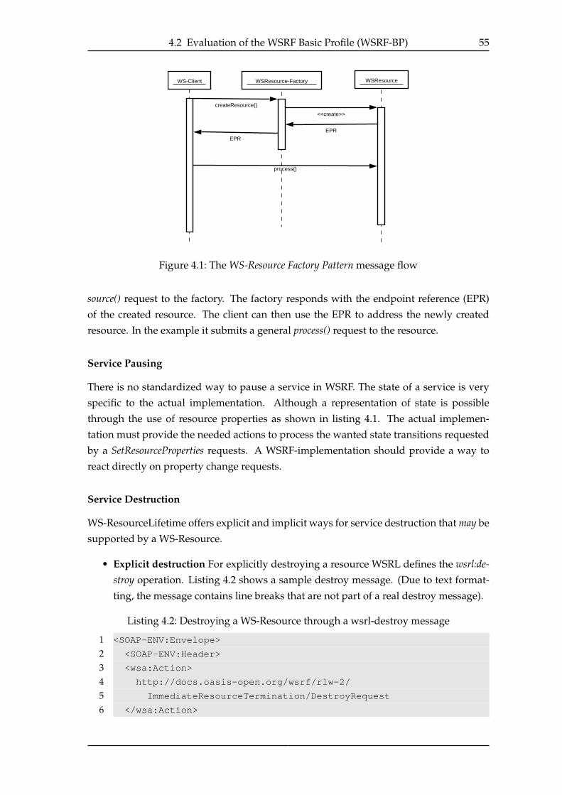
4.2 Evaluation of the WSRF Basic Profile (WSRF-BP) 55
WS-Client WSResource-Factory
createResource()
WSResource
<<create>>
EPR
EPR
process()
Figure 4.1: The WS-Resource Factory Pattern message flow
source() request to the factory. The factory responds with the endpoint reference (EPR)
of the created resource. The client can then use the EPR to address the newly created
resource. In the example it submits a general process() request to the resource.
Service Pausing
There is no standardized way to pause a service in WSRF. The state of a service is very
specific to the actual implementation. Although a representation of state is possible
through the use of resource properties as shown in listing 4.1. The actual implemen-
tation must provide the needed actions to process the wanted state transitions requested
by a SetResourceProperties requests. A WSRF-implementation should provide a way to
react directly on property change requests.
Service Destruction
WS-ResourceLifetime offers explicit and implicit ways for service destruction that may be
supported by a WS-Resource.
• Explicit destruction For explicitly destroying a resource WSRL defines the wsrl:de-stroy operation. Listing 4.2 shows a sample destroy message. (Due to text format-
ting, the message contains line breaks that are not part of a real destroy message).
Listing 4.2: Destroying a WS-Resource through a wsrl-destroy message
1 <SOAP-ENV:Envelope>
2 <SOAP-ENV:Header>
3 <wsa:Action>
4 http://docs.oasis-open.org/wsrf/rlw-2/
5 ImmediateResourceTermination/DestroyRequest
6 </wsa:Action>

56 4 Service Runtime Evaluation
7 <wsa:To>http://example.com/PaiService</wsa:To>
8 <wsa:ReferenceParameters>
9 <ResourceId>1</ResourceId>
10 </wsa:ReferenceParameters>
11 </SOAP-ENV:Header>
12 <SOAP-ENV:Body>
13 <wsrf-rl:Destroy/>
14 </SOAP-ENV:Body>
15 </SOAP-ENV:Envelope>
• Implicit/Scheduled Destruction In many scenarios it is common that resources
have an initial lifetime when created. For example the shopping cart from section
2.5.1 would have an initial lifetime in which it is available for the customer before
it is deleted automatically. This can be compared to a maximum session lease time
of a web application.
For using implicit resource destruction, the properties wsrf-rl:TerminationTime and
wsrf-rl:CurrentTime must be included in the RP-document of the according resource.
The destruction of a resource can be scheduled by setting the termination time to a
desired time. To let a service requester set a resource termination time without re-
quiring a specific accuracy of clock synchronization between the service requester
and the service provider, the WS-Resource offers the current time property, which
represents the local time of the resource.
Termination time can be scheduled by setting an explicit time by a setResourceProp-
erty() call or by specifying a time offset from the current time which the resource
uses to calculate the corresponding new termination time.
4.2.2 Registry Service
Section 3.3.1 stated the necessity of a registry service that is capable to provide state infor-
mation about the registered entries. WSRF offers the needed functionality with the WS-
Resource called ServiceGroup (section 2.5.3). Generally speaking, these service groups
can combine arbitrary WS-Resources and Web Services. By applying a so-called Member-shipContentRules, the set of allowed WS-Resources for a service group can be restricted.
The same mechanism can be used to enrich the entries of the service group with state in-
formation about the members. Listing 4.3 illustrates, how a simple rule is defined within
a WS-ResourceMetadata descriptor. As the membership rules of a service group are re-
alized as resource properties, the rule is applied by setting a static property value. The
rule dictates the existence of the muws2:OperationalStatus property for all WS-Resources
that should be added to the service group. The property will automatically added to the
Content property of the entry elements.
4.2 Evaluation of the WSRF Basic Profile (WSRF-BP) 57
Listing 4.3: MembershipContentRule which restricts the registry to WS-Resources with
the OperationalStatus property
1 <wsrmd:MetadataDescriptor
2 interface="wsrf-sg:ServiceGroupRP"
3 name="ServiceGroupMetadata">
4 <wsrmd:Property
5 name="wsrf-sg:MembershipContentRule">
6 <wsrmd:StaticValues>
7 <wsrf-sg:MembershipContentRule
8 ContentElements="muws2:OperationalStatus"/>
9 </wsrmd:StaticValues>
10 </wsrmd:Property>
11 </wsrmd:MetadataDescriptor>
When querying the service group about its members, the responses will contain the value
of the OperationalStatus of the members. A workload management resource could use
these information for load balancing and scheduling.
4.2.3 Resource State Monitoring
Having access to the state of a resource via its resource properties does not solve the
problem of effective state monitoring, when, for example, a monitoring service is only
interested in state transitions.
WSRF uses WS-BaseNotification (see section 2.5.4, [GHM06]) to provide an event-based
notification service. Notification consumers can subscribe to WSRF specific events like
resource property changes, resource termination and ServiceGroup entry additions or
removals. For example, an interested service can subscribe to changes of the property
CompletedJobs from listing 4.1 by sending a message like the one shown in listing 4.4. The
listing only shows the body-contents of the complete SOAP-Message.
Listing 4.4: Subscription message for resource changes.
1 <wsnt:Subscribe>
2 <wsnt:ConsumerReference>
3 <wsa:Address>http://host/service/ServiceGroupEntry</wsa:Address>
4 <wsa:ReferenceParameters>
5 <muse-wsa:ResourceId>ResourceId</muse-wsa:ResourceId>
6 </wsa:ReferenceParameters>
7 </wsnt:ConsumerReference>
8 <wsnt:Filter>
9 <wsnt:TopicExpression
10 Dialect="http://[...]/wsn/t-1/TopicExpression/Concrete">
11 cmgrid:CompletedJobs
12 </wsnt:TopicExpression>
13 </wsnt:Filter>
14 </wsnt:Subscribe>

58 4 Service Runtime Evaluation
Every time the CompletedJobs property gets changed, all subscribers get a so-called Re-sourcePropertyValueChangeNotification message. An excerpt of such a message is shown in
listing 4.5.
Listing 4.5: Sample resource change notification for a subscription as in listing 4.4
1 <wsnt:Notify xmlns:wsnt="http://docs.oasis-open.org/wsn/b-2">
2 <wsnt:NotificationMessage>
3 <wsnt:SubscriptionReference>
4 <!-- subscriber -->
5 </wsnt:SubscriptionReference>
6 <wsnt:Topic>
7 cmgrid:CompletedJobs
8 </wsnt:Topic>
9 <wsnt:ProducerReference>
10 <!-- monitored resource / producer -->
11 </wsnt:ProducerReference>
12 <wsnt:Message>
13 <wsrf-rp:ResourcePropertyValueChangeNotification>
14 <wsrf-rp:OldValues>
15 <cmgrid:CompletedJobs>99</cmgrid:CompletedJobs>
16 </wsrf-rp:OldValues>
17 <wsrf-rp:NewValues>
18 <cmgrid:CompletedJobs>100</cmgrid:CompletedJobs>
19 </wsrf-rp:NewValues>
20 </wsrf-rp:ResourcePropertyValueChangeNotification>
21 </wsnt:Message>
22 </wsnt:NotificationMessage>
23 </wsnt:Notify>
This event- and topic-based monitoring reduces message exchanges. Subscriptions can
be paused and deleted and external monitoring systems can subscribe to resources, with-
out knowledge of the EAM system. Only the monitored WS-Resources are aware of the
external subscriber. Nevertheless, how effective and scalable SOAP-based application
monitoring is in for practical implementations has to be tested by experiments.
4.2.4 Summary
The WSRF and WSN specifications allow a flexible and standardized way to specify and
access stateful resources through standardized Web Services. By subscribing to a resource
property change, interested clients will be notified automatically by WS-Notification.
This allows flexible application-based monitoring that can be switched on and off with-
out interfering with the running application. External management and monitoring tools
can access application data transparently without the knowledge of the EAM service.
On the other side, the lack of semantics forces all clients to be aware of the meaning of
resource properties. WSRF does not define a way to describe the properties in more de-

4.3 The Use of WSDM to Achieve Manageability 59
tail. WSRF ServiceGroups offer a simple way to aggregate resources for discovery, but
complex relationships between resources can not be described.
4.3 The Use of WSDM to Achieve Manageability
The last section showed that the WSRF-BP is sufficient for the required virtualization and
manageability functionalities. Nevertheless, this can only be achieved by the use of pro-
prietary semantics defined for the used resource properties.
The Web Services Distributed Management (WSDM) specification (see section 2.6) pro-
mises to enable better manageability of resources. Generally, WSDM enriches WSRF with
management-specific semantics and definitions that should allow a standardized man-
agement of resources in a distributed environment.
The specification consists of the two parts Management Using Web Services (MUWS) and
Management Of Web Services (MOWS) (see section 2.6. As the intention of this section is
to find a service runtime that can be used to manage other resources, this evaluation will
only analyze the MUWS part of WSDM.
4.3.1 Metrics and Metadata
WSDM MUWS defines a set of extensions on top of WSRF to enrich the resource proper-
ties of a resource with metadata or to declare them as metrics.
Figure 4.2: State diagram for the operational state of a resource
Listing 4.6: Construction of a state taxonomy
1 <xsd:element name="UnavailableState" >
2 <xsd:complexType>
3 <xsd:complexContent>
4 <xsd:restriction base="muws2:OperationalState" />
5 </xsd:complexContent>
6 </xsd:complexType>
7 </xsd:element>

60 4 Service Runtime Evaluation
89 <xsd:element name="AvailableState" >
10 <xsd:complexType>
11 <xsd:complexContent>
12 <xsd:restriction base="muws2:OperationalState" />
13 </xsd:complexContent>
14 </xsd:complexType>
15 </xsd:element>
1617 <!-- The idle state is a substate of the available state -->
18 <xsd:element name="IdleState" >
19 <xsd:complexType>
20 <xsd:complexContent>
21 <xsd:restriction base="cmgrid:AvailableState" />
22 </xsd:complexContent>
23 </xsd:complexType>
24 </xsd:element>
Listing 4.6 shows the XML representation of the states Unavailable, Idle and the state
Available. The Available consists of the sub-states Idle, Running, Stopping and Stopped.
Both, the Unavailable and Available states are sub-states of the common cmgrid:Opera-
tionalState. The idle state in line 18 is a restriction of the Available state to indicate that it
is a sub-state of Available.
4.3.2 A WSDM-based Resource Model
With the use of WSRF ServiceGroups, a representation of the used resources within the
system can be implemented, although this simple aggregation of resources does not build
a correct and complete resource model of the project. Another restriction of Service-
Groups to build a resource model is that all entries in the group have to be a WS-Resource
or Web Service. WSDM MUWS can be used to create a new or to expose an existing re-
source model through a Web Service endpoint.
The intended archiving system consists of a couple of components, which will be mod-
eled as resources or services. A simplified, high-level schema of this containment associ-
ation is shown in figure 4.3. The example illustrates an archiving service containing the
components Registry, Dispatcher and Crawler, whereas Dispatcher and Crawler are part
of the required workload manager (see [Biß07]).
WSDM MUWS offers the manageability capability muws2:Relationships (see 2.6.1) to mo-
del this kind of associations. The capability requires the existence of the muws2:Relation-ship property within the ResourceProperties document of the resource, which will hold
and expose the resource model. An instance of a relationship element representing the
model from figure 4.3 is shown in listing 4.7.

4.3 The Use of WSDM to Achieve Manageability 61
Figure 4.3: Simplified resource model
Listing 4.7: The use of the WSDM MUWS RelationshipType to create a resource model
1 <?xml version="1.0" encoding="UTF-8"?>
2 <muws2:Relationship>
3 <muws2:Name>Service contained in an external service</muws2:Name>
4 <muws2:Type>
5 <cmgrid:ContainmentType/> <!-- user defined type -->
6 </muws2:Type>
7 <!-- Archiving Service -->
8 <muws2:Participant>
9 <muws2:Role> <!-- user defined role -->
10 cmgrid:roles:external:archiving-service
11 </muws2:Role>
12 <muws1:ManageabilityEndpointReference/>
13 <muws2:ResourceId><!-- ArchivingServiceID --></muws2:ResourceId>
14 </muws2:Participant>
15 <!-- Contained services -->
16 <muws2:Participant>
17 <muws2:Role>
18 cmgrid:roles:internal:registry
19 </muws2:Role>
20 <muws1:ManageabilityEndpointReference>
21 <!-- RegistryEPR -->
22 </muws1:ManageabilityEndpointReference>
23 </muws2:Participant>
24 <muws2:Participant>
25 <muws2:Role>
26 cmgrid:roles:internal:dispatcher
27 </muws2:Role>
28 <muws1:ManageabilityEndpointReference>
29 <!-- DispatcherEPR -->
30 </muws1:ManageabilityEndpointReference>
31 </muws2:Participant>
32 <muws2:Participant>
33 <muws2:Role>
62 4 Service Runtime Evaluation
34 cmgrid:roles:internal:crawler
35 </muws2:Role>
36 <muws1:ManageabilityEndpointReference>
37 <!-- CrawlerEPR -->
38 </muws1:ManageabilityEndpointReference>
39 </muws2:Participant>
40 </muws2:Relationship>
The defined relationship has the exemplary, user-defined type cmgrid:ContainmentTypeand a participant element for each component of figure 4.3, which shall be connected by
this relationship. The role element of each participant defines the role it plays in the rela-
tionship. These role types are project-specific and should be defined and described in the
declaration of the particular relationship type (in this case the cmgrid:ContainmentType).
4.3.3 Summary
By using the WSDM specification for the creation of manageability endpoints, the oppor-
tunity of using existing or emerging WSDM-aware tools for management or monitoring
is given. A data center wide solution for resource management could be used instead of
an EAM service specific WSRF based solution with service specific semantics. By using
the resource modeling capabilities, external tools can monitor the complete system by
expanding all defined relationships.
4.4 Evaluation of WSRF Implementations
After evaluating the theoretical usage of the WSRF Basic Profile, this section will analyze
existing implementations of the standard.
4.4.1 Existing WSRF Implementations
Currently (October 2006) only two open-source Java implementations of WSRF are avail-
able that could fit as the service runtime for the EAM system.
1. Globus Toolkit 4 - Java WS Core (stated as GT4)
2. Apache Muse 2 (stated as Muse)
4.4.2 Globus Toolkit 4 (GT4)
The Globus Toolkit 4 is the reference implementation of OGSA 1.0 and its development
process had a direct influence on the OGSA specification. Besides a WSRF implementa-
tion within the WS Core (available in Java, C and Python), the toolkit implements dif-
ferent OGSA capabilities as shown in figure 4.4. With version 4.0 of the toolkit, WSRF
is used as the underlying grid service infrastructure. Although OGSA advises that all

4.4 Evaluation of WSRF Implementations 63
Figure 4.4: Globus Toolkit 4 architecture overview (http://www.globus.org/toolkit/)
other services should build on the grid infrastructure, many toolkit components are not
WSRF-compliant yet, as they were implemented before OGSA or WSRF were defined. It
is likely that these components will be refactored in upcoming releases of the toolkit.
GT4 focuses on the classical view of Grid computing, by providing an infrastructure
which enables resource sharing “across corporate, institutional, and geographic bound-
aries without sacrificing local autonomy” 2. Especially the security components of GT4
are designed for this distributed approach. The intended EAM system will likely not
run across corporate boundaries, but stay within a closed infrastructure. Security con-
cepts for the system could be reached within application logic and will not be discussed
any further. As the Globus Toolkit is separated into different modules, single modules
can be installed as stand-alone components. The Information Services components (figure
4.4) will be included in the ongoing discussion, as they are directly using the underlying
WSRF services.
4.4.3 Apache Muse
Apache Muse (Muse) is a Java-based framework that covers the WSRF-Basic Profile and
the MUWS-part of the Web Services Distributed Management (WSDM) standard. Muse
2http://www.globus.org/toolkit/about.html, visited 03/12/2007

64 4 Service Runtime Evaluation
is based on the IBM alphaWorks Autonomic Integrated Development Environment3, whose
runtime source code was contributed to the Apache Muse project in June 2006. The also
existing tooling components for WSDM were contributed to the Eclipse project4 and are
developed in collaboration with the Apache Muse team.
Muse can be deployed as a stand-alone web application or as a Axis25 service into a J2EE
container. As a third possibility, an OSGi6 resource bundle can be created, which can be
run in an OSGi container as e.g. Eclipse Equinox 7.
For the ongoing comparison, the Axis2-based deployment method is used, as it is the
most robust version yet (as of December 2006) and offers the possibility of using Axis2plug-in modules like e.g. WS-Security.
4.4.4 Performance Comparison
By using Web Services as the basis for a distributed infrastructure, XML processing is
becoming a critical part when it comes to system performance.
Using SOAP - Trade-off between Universality and High-performance
SOAP abstracts message transportation and addressing from the underlying transporta-
tion layer. One can either use standard HTTP request-response communication or decou-
pled WS-Addressing-based communication. With the growth of possibilities comes an
decrease of overall performance. For each communication step the system has to parse
incoming and create new outgoing XML messages. When using a SOAP-based com-
munication, XML processing performance becomes even more important [HGvEZ06],
[CGB02] for the overall performance of a system.
XML Processing
A real performance comparison between GT4 and Muse would include a significant
benchmark test. As this would imply benchmark implementations for both solutions,
this could not be done in this thesis.
The underlying Web Services layer of both implementations has a great impact in pro-
cessing performance. For each request, the incoming SOAP-message has to be analyzed,
parsed and passed to the WSRF-stack. A comparison of Apache Axis1 and Axis2 as the
used Web Services stacks, will result in a meaningful direction of the overall performance.
Axis1 is one of the most used Web Services implementations of recent years and had a
great influence on the success of Web Services. With the move from Axis1 to Axis2, the
3http://www.alphaworks.ibm.com/tech/aide, last visited 03/12/20074http://www.eclipse.org5http://ws.apache.org/axis2/6http://www.osgi.org/7http://www.eclipse.org/equinox/

4.4 Evaluation of WSRF Implementations 65
Apache community switched from a SAX-based8 to a StAX-based9 XML-parsing API.
Without discussing the general differences between SAX and StAX, especially when it
comes to SOAP communication with WS-Addressing, the use of a StAX-parser has sev-
eral advantages. To pass a SOAP message to the WSRF-layer, the Web Services stack has
to read the SOAP-Header to get the address of the final receiver of the message. With
SAX, during the parsing-phase, the complete XML document has to be processed, al-
though the application is only interested in the SOAP-Header [PHE+06]. With a growing
message size, this can have a great influence on processing performance. StAX enables
the application to pause the parsing process at any time. By this, after parsing the SOAP
Headers, the message can be directly passed to the corresponding handlers (receivers).
Based on the SOAP Benchmark V1 and V210 (see [GSC+04], [HGS+05] and [HGvEZ06])
Devanum Sirinivas of WSO211 compared the SOAP processing performance of Axis1 ver-
sion 1.4 and an Axis2 version 1.012. The benchmark emulates standard workloads which
appear typically in a WSRF environment with a lot of property requests. Sources and
results of the benchmark can be viewed and accessed at http://wso2.org/library/
91. The comparison shows that Axis2 works four to five times faster than Axis1, espe-
cially when processing complex XML types.
4.4.5 Programming Model
Being the base for a longtime project, the programming model of the WSRF-implemen-
tation should be clear, understandable and easy to learn, to support later changes and
enhancements of the project. This section will analyze and compare the programming
models of GT4 and Apache Muse.
GT4 Programming Model
The programming model of GT4 carries the concept of the implied resource pattern (see
2.5.2) down to the implementation level.
In general a developer has to implement three main components to create a WS-Resource.
• The service object represents the stateless part of the WS-Resource construct. From
the client point of view all operations offered by the provider are implemented by
the service, although internal theses operations can be implemented by the use of
reusable operation providers.
• The resource object represents the resource defined by the ResourceProperties doc-
ument referred in the portType definition in the corresponding WSDL-file (see sec-
8SAX = Simple API for XML9StAX = Streaming API for XML
10http://grid.cs.binghamton.edu/projects/soap_bench/ - 05/200711WSO2 is a Open Source technology company. http://www.wso2.com12The used version was a source snapshot from May 15,2006
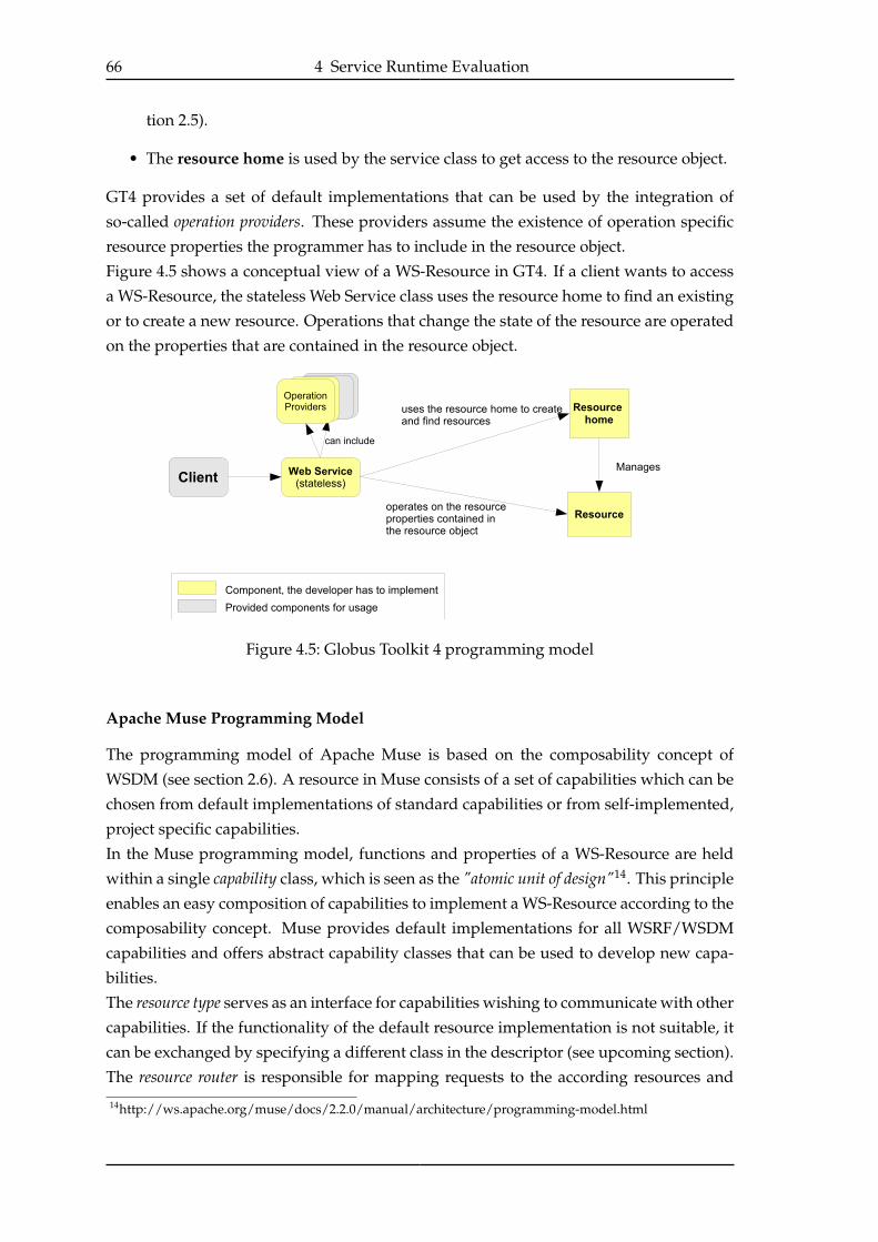
66 4 Service Runtime Evaluation
tion 2.5).
• The resource home is used by the service class to get access to the resource object.
GT4 provides a set of default implementations that can be used by the integration of
so-called operation providers. These providers assume the existence of operation specific
resource properties the programmer has to include in the resource object.
Figure 4.5 shows a conceptual view of a WS-Resource in GT4. If a client wants to access
a WS-Resource, the stateless Web Service class uses the resource home to find an existing
or to create a new resource. Operations that change the state of the resource are operated
on the properties that are contained in the resource object.
Figure 4.5: Globus Toolkit 4 programming model
Apache Muse Programming Model
The programming model of Apache Muse is based on the composability concept of
WSDM (see section 2.6). A resource in Muse consists of a set of capabilities which can be
chosen from default implementations of standard capabilities or from self-implemented,
project specific capabilities.
In the Muse programming model, functions and properties of a WS-Resource are held
within a single capability class, which is seen as the "atomic unit of design"14. This principle
enables an easy composition of capabilities to implement a WS-Resource according to the
composability concept. Muse provides default implementations for all WSRF/WSDM
capabilities and offers abstract capability classes that can be used to develop new capa-
bilities.
The resource type serves as an interface for capabilities wishing to communicate with other
capabilities. If the functionality of the default resource implementation is not suitable, it
can be exchanged by specifying a different class in the descriptor (see upcoming section).
The resource router is responsible for mapping requests to the according resources and
14http://ws.apache.org/muse/docs/2.2.0/manual/architecture/programming-model.html

4.4 Evaluation of WSRF Implementations 67
Figure 4.6: Apache Muse programming model13
works transparently to the developer. Muse resources can be deployed in J2EE, OSGi
and J2ME environments. The environment-specific isolation layer offers a unified envi-
ronment for the resource implementations.
For testing different service granularities introduced in [Biß07], the programming model
of Apache Muse offers a flexible way for implementations. By combining only functional
aspects into one capability, a future combination of these capabilities to one or more WS-
Resources is possible at deployment time. The possibility of accessing informations about
implemented capabilities of a resource during runtime allows a flexible way to realize dif-
ferent service granularities. Listing 4.8 shows a possible way how Muse capabilities can
be implemented to support fine or large grained services. The example shows an excerpt
of a possible “parsing-capability" implementation, which has to dispatch a jobDocument
to an either a local "indexing-capability" or a remote "indexing-service".
Listing 4.8: "Pseudo-code” for a possible usage of the composability concept to realize
different service granularities
1 //Does the resource also implement the indexing-capability?
2 if(getResource.hasCapability("indexing")){
3 //if yes, execute the index process remotely
4 getResource().getCapability("indexing").process(jobDocument);
5 }else{
6 //otherwise, retrieve an indexing-service from the registry
7 IndexService index = getRegistry.lookupService("indexing");
8 index.process(jobDocument);
9 }
4.4.6 Code Generation and Data Binding
When it comes to code generation, both toolkits offer nearly the same functionalities.
Starting with the WSDL-file, a WSDL2Java command-line tool generates stub-classes, for
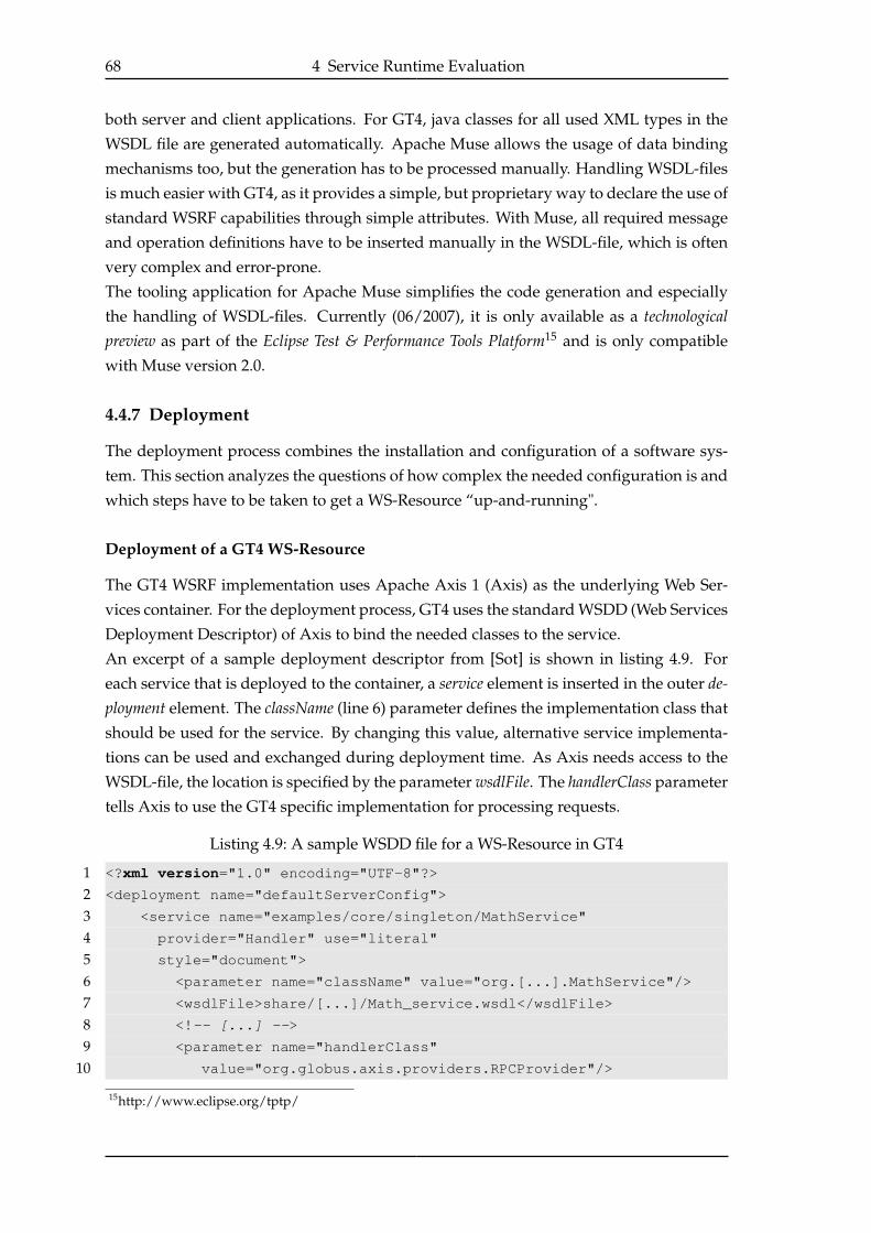
68 4 Service Runtime Evaluation
both server and client applications. For GT4, java classes for all used XML types in the
WSDL file are generated automatically. Apache Muse allows the usage of data binding
mechanisms too, but the generation has to be processed manually. Handling WSDL-files
is much easier with GT4, as it provides a simple, but proprietary way to declare the use of
standard WSRF capabilities through simple attributes. With Muse, all required message
and operation definitions have to be inserted manually in the WSDL-file, which is often
very complex and error-prone.
The tooling application for Apache Muse simplifies the code generation and especially
the handling of WSDL-files. Currently (06/2007), it is only available as a technologicalpreview as part of the Eclipse Test & Performance Tools Platform15 and is only compatible
with Muse version 2.0.
4.4.7 Deployment
The deployment process combines the installation and configuration of a software sys-
tem. This section analyzes the questions of how complex the needed configuration is and
which steps have to be taken to get a WS-Resource “up-and-running".
Deployment of a GT4 WS-Resource
The GT4 WSRF implementation uses Apache Axis 1 (Axis) as the underlying Web Ser-
vices container. For the deployment process, GT4 uses the standard WSDD (Web Services
Deployment Descriptor) of Axis to bind the needed classes to the service.
An excerpt of a sample deployment descriptor from [Sot] is shown in listing 4.9. For
each service that is deployed to the container, a service element is inserted in the outer de-ployment element. The className (line 6) parameter defines the implementation class that
should be used for the service. By changing this value, alternative service implementa-
tions can be used and exchanged during deployment time. As Axis needs access to the
WSDL-file, the location is specified by the parameter wsdlFile. The handlerClass parameter
tells Axis to use the GT4 specific implementation for processing requests.
Listing 4.9: A sample WSDD file for a WS-Resource in GT4
1 <?xml version="1.0" encoding="UTF-8"?>
2 <deployment name="defaultServerConfig">
3 <service name="examples/core/singleton/MathService"
4 provider="Handler" use="literal"
5 style="document">
6 <parameter name="className" value="org.[...].MathService"/>
7 <wsdlFile>share/[...]/Math_service.wsdl</wsdlFile>
8 <!-- [...] -->
9 <parameter name="handlerClass"
10 value="org.globus.axis.providers.RPCProvider"/>
15http://www.eclipse.org/tptp/
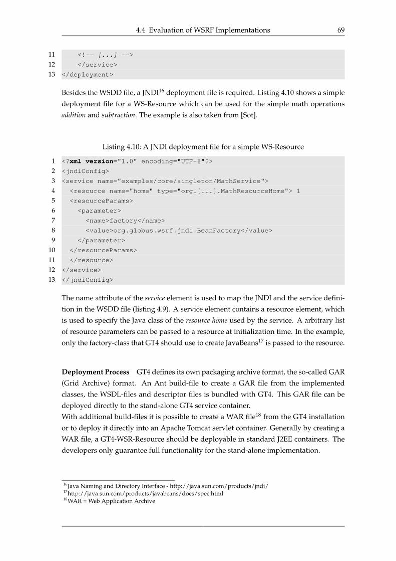
4.4 Evaluation of WSRF Implementations 69
11 <!-- [...] -->
12 </service>
13 </deployment>
Besides the WSDD file, a JNDI16 deployment file is required. Listing 4.10 shows a simple
deployment file for a WS-Resource which can be used for the simple math operations
addition and subtraction. The example is also taken from [Sot].
Listing 4.10: A JNDI deployment file for a simple WS-Resource
1 <?xml version="1.0" encoding="UTF-8"?>
2 <jndiConfig>
3 <service name="examples/core/singleton/MathService">
4 <resource name="home" type="org.[...].MathResourceHome"> 1
5 <resourceParams>
6 <parameter>
7 <name>factory</name>
8 <value>org.globus.wsrf.jndi.BeanFactory</value>
9 </parameter>
10 </resourceParams>
11 </resource>
12 </service>
13 </jndiConfig>
The name attribute of the service element is used to map the JNDI and the service defini-
tion in the WSDD file (listing 4.9). A service element contains a resource element, which
is used to specify the Java class of the resource home used by the service. A arbitrary list
of resource parameters can be passed to a resource at initialization time. In the example,
only the factory-class that GT4 should use to create JavaBeans17 is passed to the resource.
Deployment Process GT4 defines its own packaging archive format, the so-called GAR
(Grid Archive) format. An Ant build-file to create a GAR file from the implemented
classes, the WSDL-files and descriptor files is bundled with GT4. This GAR file can be
deployed directly to the stand-alone GT4 service container.
With additional build-files it is possible to create a WAR file18 from the GT4 installation
or to deploy it directly into an Apache Tomcat servlet container. Generally by creating a
WAR file, a GT4-WSR-Resource should be deployable in standard J2EE containers. The
developers only guarantee full functionality for the stand-alone implementation.
16Java Naming and Directory Interface - http://java.sun.com/products/jndi/17http://java.sun.com/products/javabeans/docs/spec.html18WAR = Web Application Archive

70 4 Service Runtime Evaluation
Deployment of a WS-Resource with Apache Muse
The composability concept is directly visible in the muse deployment descriptor. Its main el-
ements will be described with the use of an extract from a sample descriptor file in listing
4.11. Each resource of an Apache Muse project is represented by a resource-type element
(line 4). Each resource-type element describes its context-path (line 5), which represents
the context-path of the address-element of its endpoint reference (see section 2.5.2). The
wsdl element references the used WSDL-file and portType. The java-resource-class (line 13)
defines the base class of the resource. As shown in figure 4.6, this class aggregates a set
of capabilities and acts as an interface for inter-capability access.
Each Muse capability is represented as a capability-element inside the resource-type. It
consists of the capability-specific URI which corresponds to the unique identifier de-
manded by WSDM and the java-capability-class, which implements this capability. The
composability of common and resource-specific capabilities is shown by the use of the
standardized GetResourceProperty capability and its default implementation (line 17)
and the resource specific MyCapability in line 30.
Listing 4.11: A sample Apache Muse deployment descriptor for a WS-Resource
1 <?xml version="1.0" encoding="UTF-8" ?>
2 <muse>
3 [...]
4 <resource-type>
5 <context-path>WsResource</context-path>
6 <wsdl>
7 <wsdl-file>/wsdl/WsResource.wsdl</wsdl-file>
8 <wsdl-port-type>test:WsResourcePortType</wsdl-port-type>
9 </wsdl>
10 <java-id-factory-class>
11 org.apache.muse.core.routing.RandomResourceIdFactory
12 </java-id-factory-class>
13 <java-resource-class>
14 org.apache.muse.ws.resource.impl.SimpleWsResource
15 </java-resource-class>
16 [...]
17 <capability>
18 <capability-uri>
19 http://docs.oasis-open.org/wsrf/rpw-2/Get
20 </capability-uri>
21 <java-capability-class>
22 org.apache.muse.ws.resource.properties.get.impl.SimpleGetCapability
23 </java-capability-class>
24 </capability>
25 <capability>
26 <capability-uri>
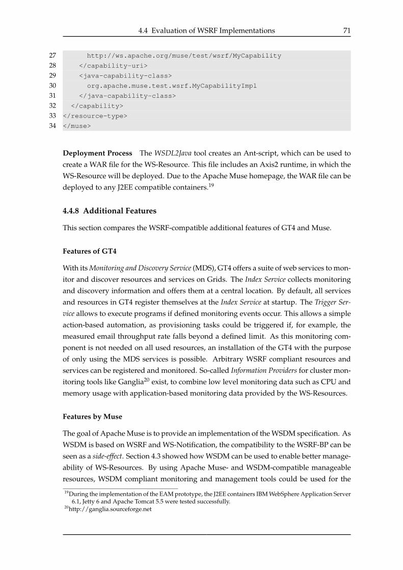
4.4 Evaluation of WSRF Implementations 71
27 http://ws.apache.org/muse/test/wsrf/MyCapability
28 </capability-uri>
29 <java-capability-class>
30 org.apache.muse.test.wsrf.MyCapabilityImpl
31 </java-capability-class>
32 </capability>
33 </resource-type>
34 </muse>
Deployment Process The WSDL2Java tool creates an Ant-script, which can be used to
create a WAR file for the WS-Resource. This file includes an Axis2 runtime, in which the
WS-Resource will be deployed. Due to the Apache Muse homepage, the WAR file can be
deployed to any J2EE compatible containers.19
4.4.8 Additional Features
This section compares the WSRF-compatible additional features of GT4 and Muse.
Features of GT4
With its Monitoring and Discovery Service (MDS), GT4 offers a suite of web services to mon-
itor and discover resources and services on Grids. The Index Service collects monitoring
and discovery information and offers them at a central location. By default, all services
and resources in GT4 register themselves at the Index Service at startup. The Trigger Ser-vice allows to execute programs if defined monitoring events occur. This allows a simple
action-based automation, as provisioning tasks could be triggered if, for example, the
measured email throughput rate falls beyond a defined limit. As this monitoring com-
ponent is not needed on all used resources, an installation of the GT4 with the purpose
of only using the MDS services is possible. Arbitrary WSRF compliant resources and
services can be registered and monitored. So-called Information Providers for cluster mon-
itoring tools like Ganglia20 exist, to combine low level monitoring data such as CPU and
memory usage with application-based monitoring data provided by the WS-Resources.
Features by Muse
The goal of Apache Muse is to provide an implementation of the WSDM specification. As
WSDM is based on WSRF and WS-Notification, the compatibility to the WSRF-BP can be
seen as a side-effect. Section 4.3 showed how WSDM can be used to enable better manage-
ability of WS-Resources. By using Apache Muse- and WSDM-compatible manageable
resources, WSDM compliant monitoring and management tools could be used for the
19During the implementation of the EAM prototype, the J2EE containers IBM WebSphere Application Server6.1, Jetty 6 and Apache Tomcat 5.5 were tested successfully.
20http://ganglia.sourceforge.net
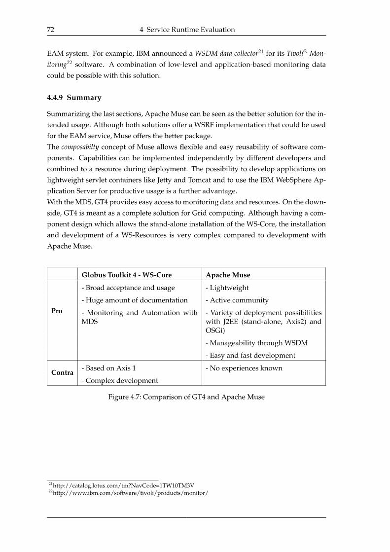
72 4 Service Runtime Evaluation
EAM system. For example, IBM announced a WSDM data collector21 for its Tivoli® Mon-itoring22 software. A combination of low-level and application-based monitoring data
could be possible with this solution.
4.4.9 Summary
Summarizing the last sections, Apache Muse can be seen as the better solution for the in-
tended usage. Although both solutions offer a WSRF implementation that could be used
for the EAM service, Muse offers the better package.
The composabilty concept of Muse allows flexible and easy reusability of software com-
ponents. Capabilities can be implemented independently by different developers and
combined to a resource during deployment. The possibility to develop applications on
lightweight servlet containers like Jetty and Tomcat and to use the IBM WebSphere Ap-
plication Server for productive usage is a further advantage.
With the MDS, GT4 provides easy access to monitoring data and resources. On the down-
side, GT4 is meant as a complete solution for Grid computing. Although having a com-
ponent design which allows the stand-alone installation of the WS-Core, the installation
and development of a WS-Resources is very complex compared to development with
Apache Muse.
Globus Toolkit 4 - WS-Core Apache Muse
Pro
- Broad acceptance and usage - Lightweight
- Huge amount of documentation - Active community
- Monitoring and Automation withMDS
- Variety of deployment possibilitieswith J2EE (stand-alone, Axis2) andOSGi)
- Manageability through WSDM
- Easy and fast development
Contra- Based on Axis 1 - No experiences known
- Complex development
Figure 4.7: Comparison of GT4 and Apache Muse
21http://catalog.lotus.com/tm?NavCode=1TW10TM3V22http://www.ibm.com/software/tivoli/products/monitor/

73
5 IBM Dynamic Infrastructure andWebSphere XD
5.1 IBM Dynamic Infrastructure (IDI)
IBM Dynamic Infrastructure (IDI) refers to itself as a so called On Demand Operating En-vironment (ODOE). Originally it was created as an ODOE for the products of the SAP
mySAP Business Suite1, and was called IBM Dynamic Infrastructure for mySAP BusinessSuite.
IDI offers an infrastructure for data center automation and management tasks. It inte-
grates typical installation, configuration and management capabilities within a central
workflow and provides all actions under a single user interface.
5.1.1 On Demand Service
An On Demand Service (ODS) can be regarded as the context necessary e.g. to provide
resources, to meter resource consumption and correlate it to the consumers (acting in the
context of the subscriber). An ODS will be instantiated separately for each consumer who
subscribes to it. As shown in figure 5.1, an ODS instance is represented by a subscription.
Each subscription is based on an offering-document, which describes and defines the
ODS formally. More information about the offering and the subscription will follow in
the upcoming sections.
Figure 5.1: Offering and subscription in the concept of an on demand service
1SAP Business Suite - http://www.sap.com/germany/solutions/business-suite

74 5 IBM Dynamic Infrastructure and WebSphere XD
5.1.2 The IBM DI Resource Model (DIRM)
The base component of the IBM Dynamic Infrastructure is the IBM DI Resource Model
(DIRM). The DIRM is a composition of manageable resources (MR) and relationships be-
tween them, comparable to the resource modeling functionalities of WSDM, but enriched
with defined semantics and extended relationships.
The concept of a manageable resource (MR) in IDI is similar, but not fully compatible
with a WS-Resource in WSRF or a manageable resource in WSDM. In IDI a manageable
resource is implemented as a stateful web service and has a resource identifier (resour-
ceId), a resource type (resourceType), a resource instance name (resourceInstanceName)
and a resource handle (resourceHandle) as mandatory properties.
Figure 5.2 shows a simplified version of a resource model for the EAM service, which
only shows the main resources.
The IBM DI Domain MR is the logical entry point to the DIRM. The Platform Fabric MR
provides access to a set of supportive manageable resources and helper classes which
together provide a base for all other manageable resources. As an example, the platform
fabric MR has a relationship with the FactoryRegistry MR which keeps factory MRs for
all resources in the system. A factory has a stateless create method, to instantiate new
MRs. The Subscription Registry MR is a registry for all subscriptions managed by IDI.
Other components like the user interface can use this registry to get a list of all subscrip-
tions in the system. The user can then use the subscription as an entry point for further
administrative tasks. The Subscription MR itself holds the context needed for the proper
functionality of the ODS, which was defined based on an offering during the subscription
phase (see section 5.1.4). A subscription is associated with a set of orders (orders are not
MRs), which can be applied to the related ODS MR. The MRs MeterEventLog, Report-
ingSystem and ArchivingSystem provide subscription-specific accounting capabilities.
The PlatformFabricOrderProcessingComponent (PFOPC) is responsible for the correct
processing of orders within the DIRM (more about order processing in section 5.1.3).
With the ODS MR represents the EAM On demand Service and is used as an entry point
to the service specific components. Over the Application MR all components that are
needed for the ODS are listed. These do not represent actual running service or appli-
cations, but describe structure the ODS. These application components are mapped to
the so called ServerCollection MR, which represents all server resources, that are cur-
rently allocated to the ODS. IDI encourages the use of server virtualization techniques
like VMware2 or XEN3. This approach allows a comfortable configuration of the pro-
vided servers. For example, the number of CPUs or memory can be configured per server
instance. The OS Container MR represents such a virtualization container. The actual op-
erating system, the application servers and e.g. the CM services are installed on top of
these containers. The three types of servers, represented by the OS Container MRs, are
2http://www.vmware.com/3http://www.cl.cam.ac.uk/research/srg/netos/xen/
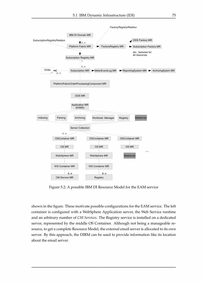
5.1 IBM Dynamic Infrastructure (IDI) 75
Figure 5.2: A possible IBM DI Resource Model for the EAM service
shown in the figure. These motivate possible configurations for the EAM service. The left
container is configured with a WebSphere Application server, the Web Service runtime
and an arbitrary number of CM Services. The Registry service is installed on a dedicated
server, represented by the middle OS Container. Although not being a manageable re-
source, to get a complete Resource Model, the external email server is allocated to its own
server. By this approach, the DIRM can be used to provide information like its location
about the email server.
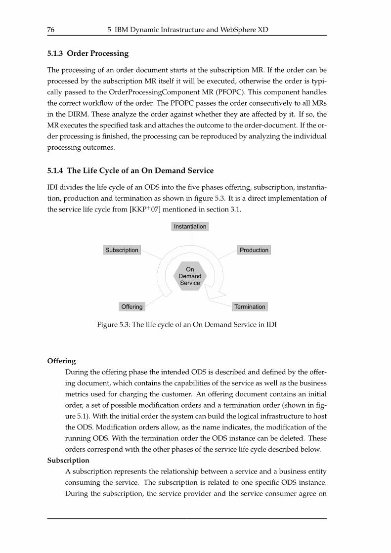
76 5 IBM Dynamic Infrastructure and WebSphere XD
5.1.3 Order Processing
The processing of an order document starts at the subscription MR. If the order can be
processed by the subscription MR itself it will be executed, otherwise the order is typi-
cally passed to the OrderProcessingComponent MR (PFOPC). This component handles
the correct workflow of the order. The PFOPC passes the order consecutively to all MRs
in the DIRM. These analyze the order against whether they are affected by it. If so, the
MR executes the specified task and attaches the outcome to the order-document. If the or-
der processing is finished, the processing can be reproduced by analyzing the individual
processing outcomes.
5.1.4 The Life Cycle of an On Demand Service
IDI divides the life cycle of an ODS into the five phases offering, subscription, instantia-
tion, production and termination as shown in figure 5.3. It is a direct implementation of
the service life cycle from [KKP+07] mentioned in section 3.1.
Figure 5.3: The life cycle of an On Demand Service in IDI
OfferingDuring the offering phase the intended ODS is described and defined by the offer-
ing document, which contains the capabilities of the service as well as the business
metrics used for charging the customer. An offering document contains an initial
order, a set of possible modification orders and a termination order (shown in fig-
ure 5.1). With the initial order the system can build the logical infrastructure to host
the ODS. Modification orders allow, as the name indicates, the modification of the
running ODS. With the termination order the ODS instance can be deleted. These
orders correspond with the other phases of the service life cycle described below.
SubscriptionA subscription represents the relationship between a service and a business entity
consuming the service. The subscription is related to one specific ODS instance.
During the subscription, the service provider and the service consumer agree on
5.1 IBM Dynamic Infrastructure (IDI) 77
the content of the initial order, which represents the initial appearance of the ODS
instance, and on the possible modification orders, including prices for the configu-
ration actions represented by the modifications.
In contrast to the offering document, which describes the service in an abstract way,
a subscription contains all necessary informations to instantiate a specific instance
of the ODS.
InstantiationIn the instantiation phase all actions are taken that are required to start the sub-
scribed service. These actions include automated deployment, installation and con-
figuration of hardware and software specified in the initial order.
ProductionThe most important phase for the customer is, of course, the production phase,
in which the service performs the demanded work, specified in the offering and
agreed to in the subscription. During this phase, the customer can apply modifica-
tion orders to change the configuration of the system. For example, a new server
can be provisioned or more memory can be allocated to an application.
TerminationAs the name indicates, in the termination phase all actions are taken to shut down
the ODS. Additionally, all resources which were assigned to the ODS are returned
to the resource pool. Operating systems and software systems installed for the
ODS are uninstalled, if necessary, to bring the resources back to a common form for
future installations.
5.1.5 Service Life Cycle Management
IDI offers management and development capabilities for all five life cycle phases de-
scribed above. Starting with the offering, IT professionals and developers have to specify
the intended ODS in an offering document. Because the contract between a provider and
a consumer closed by a subscription is based on the offering, a well defined and fully
described offering document is crucial for the success of the ODS.
5.1.6 Tooling
To create resource models for the topology of an ODS, IDI offers an UML based tooling
application called MR Designer. After drawing the structure of the manageable resources,
the developer can generate stubclasses for the manageable resources. As these are stan-
dard Java classes, an arbitrary development tool can be used for implementation.
Provisioning and configuration tasks in IDI are activated and processed by Orders. These
are developed as elements of the offering document. The offering can be designed with
the so called Offering Creator and Topology Builder. Provisioning actions can leverage stan-
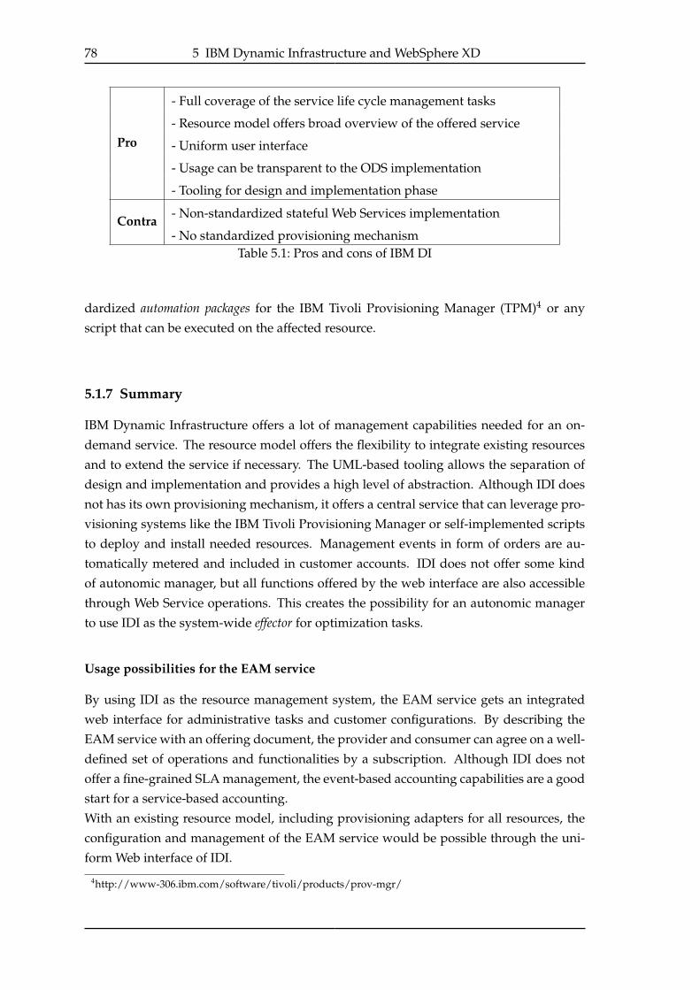
78 5 IBM Dynamic Infrastructure and WebSphere XD
Pro
- Full coverage of the service life cycle management tasks
- Resource model offers broad overview of the offered service
- Uniform user interface
- Usage can be transparent to the ODS implementation
- Tooling for design and implementation phase
Contra- Non-standardized stateful Web Services implementation
- No standardized provisioning mechanismTable 5.1: Pros and cons of IBM DI
dardized automation packages for the IBM Tivoli Provisioning Manager (TPM)4 or any
script that can be executed on the affected resource.
5.1.7 Summary
IBM Dynamic Infrastructure offers a lot of management capabilities needed for an on-
demand service. The resource model offers the flexibility to integrate existing resources
and to extend the service if necessary. The UML-based tooling allows the separation of
design and implementation and provides a high level of abstraction. Although IDI does
not has its own provisioning mechanism, it offers a central service that can leverage pro-
visioning systems like the IBM Tivoli Provisioning Manager or self-implemented scripts
to deploy and install needed resources. Management events in form of orders are au-
tomatically metered and included in customer accounts. IDI does not offer some kind
of autonomic manager, but all functions offered by the web interface are also accessible
through Web Service operations. This creates the possibility for an autonomic manager
to use IDI as the system-wide effector for optimization tasks.
Usage possibilities for the EAM service
By using IDI as the resource management system, the EAM service gets an integrated
web interface for administrative tasks and customer configurations. By describing the
EAM service with an offering document, the provider and consumer can agree on a well-
defined set of operations and functionalities by a subscription. Although IDI does not
offer a fine-grained SLA management, the event-based accounting capabilities are a good
start for a service-based accounting.
With an existing resource model, including provisioning adapters for all resources, the
configuration and management of the EAM service would be possible through the uni-
form Web interface of IDI.
4http://www-306.ibm.com/software/tivoli/products/prov-mgr/

5.2 IBM WebSphere Extended Deployment V6.0 (WXD) 79
5.2 IBM WebSphere Extended Deployment V6.0 (WXD)
IBM WebSphere XD V6.0 (WXD)5 provides virtualization and automated capabilities for
a cluster of IBM WebSphere application servers (WAS). According to IBM, it offers a so-
lution for a dynamic, reliable and adaptable infrastructure [REF+06].
WXD is an extension of IBM WAS Network Deployment V6.0.2 6, which adds central
deployment and clustering capabilities to a cluster of IBM’s standard J2EE7 WebSphere
Application Server V68.
WXD addresses a couple of requirements stated in chapter 3. In the following sections
some of these features will be presented. Afterwards, some recommendations are given
as to how WXD can be used for the EAM system.
5.2.1 On Demand Router
In an WXD production environment, the On Demand Router (ODR) acts as an entry point
to the operational system. Figure 5.4 shows a recommended topology for an WXD in-
stallation [REF+06]. Although more than one proxy server or ODR are allowed, in the
following only one proxy and one ODR will be mentioned.
The proxy server shown in figure 5.4 is needed for security reasons and is transparent for
all servers behind firewall B.
Figure 5.4: Recommended topology for an WXD operational environment (from[REF+06])
5http://www-306.ibm.com/software/webservers/appserv/extend/6http://www-306.ibm.com/software/webservers/appserv/was/network/7J2EE - Java 2 Platform, Enterprise Edition - http://java.sun.com/j2ee8IBM WebSphere Application Server - http://www-306.ibm.com/software/webservers/appserv/was/
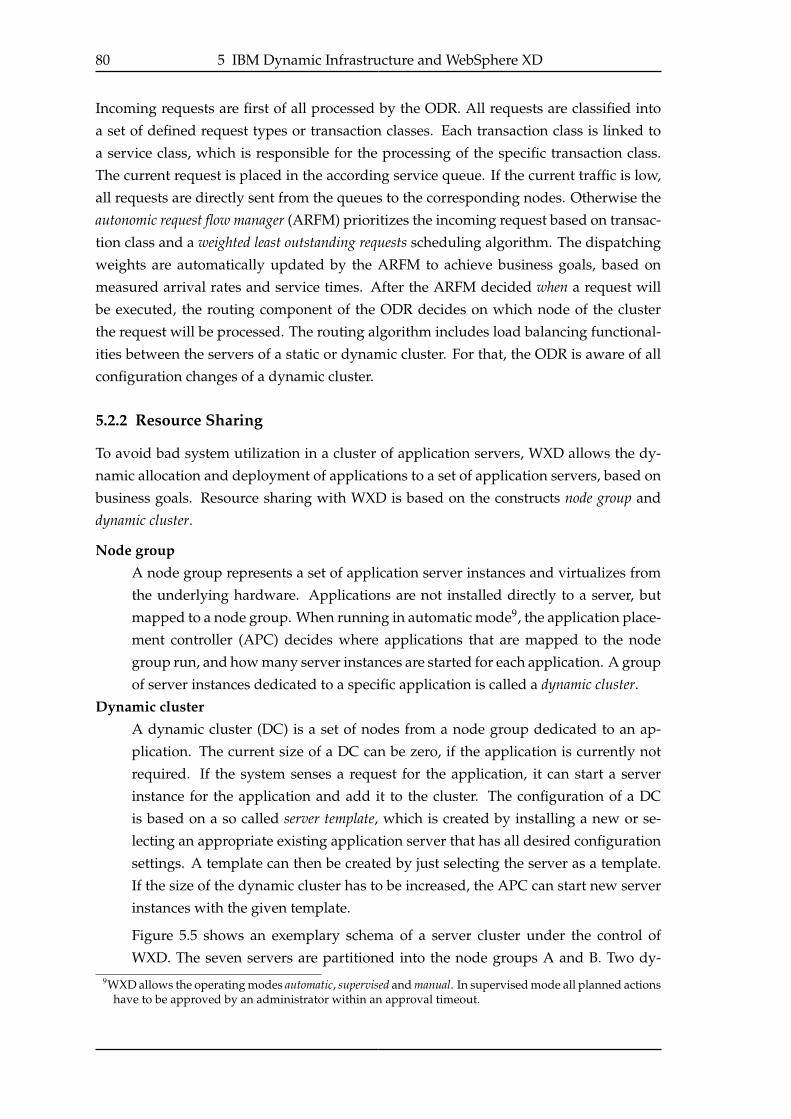
80 5 IBM Dynamic Infrastructure and WebSphere XD
Incoming requests are first of all processed by the ODR. All requests are classified into
a set of defined request types or transaction classes. Each transaction class is linked to
a service class, which is responsible for the processing of the specific transaction class.
The current request is placed in the according service queue. If the current traffic is low,
all requests are directly sent from the queues to the corresponding nodes. Otherwise the
autonomic request flow manager (ARFM) prioritizes the incoming request based on transac-
tion class and a weighted least outstanding requests scheduling algorithm. The dispatching
weights are automatically updated by the ARFM to achieve business goals, based on
measured arrival rates and service times. After the ARFM decided when a request will
be executed, the routing component of the ODR decides on which node of the cluster
the request will be processed. The routing algorithm includes load balancing functional-
ities between the servers of a static or dynamic cluster. For that, the ODR is aware of all
configuration changes of a dynamic cluster.
5.2.2 Resource Sharing
To avoid bad system utilization in a cluster of application servers, WXD allows the dy-
namic allocation and deployment of applications to a set of application servers, based on
business goals. Resource sharing with WXD is based on the constructs node group and
dynamic cluster.
Node groupA node group represents a set of application server instances and virtualizes from
the underlying hardware. Applications are not installed directly to a server, but
mapped to a node group. When running in automatic mode9, the application place-
ment controller (APC) decides where applications that are mapped to the node
group run, and how many server instances are started for each application. A group
of server instances dedicated to a specific application is called a dynamic cluster.
Dynamic clusterA dynamic cluster (DC) is a set of nodes from a node group dedicated to an ap-
plication. The current size of a DC can be zero, if the application is currently not
required. If the system senses a request for the application, it can start a server
instance for the application and add it to the cluster. The configuration of a DC
is based on a so called server template, which is created by installing a new or se-
lecting an appropriate existing application server that has all desired configuration
settings. A template can then be created by just selecting the server as a template.
If the size of the dynamic cluster has to be increased, the APC can start new server
instances with the given template.
Figure 5.5 shows an exemplary schema of a server cluster under the control of
WXD. The seven servers are partitioned into the node groups A and B. Two dy-9WXD allows the operating modes automatic, supervised and manual. In supervised mode all planned actions
have to be approved by an administrator within an approval timeout.
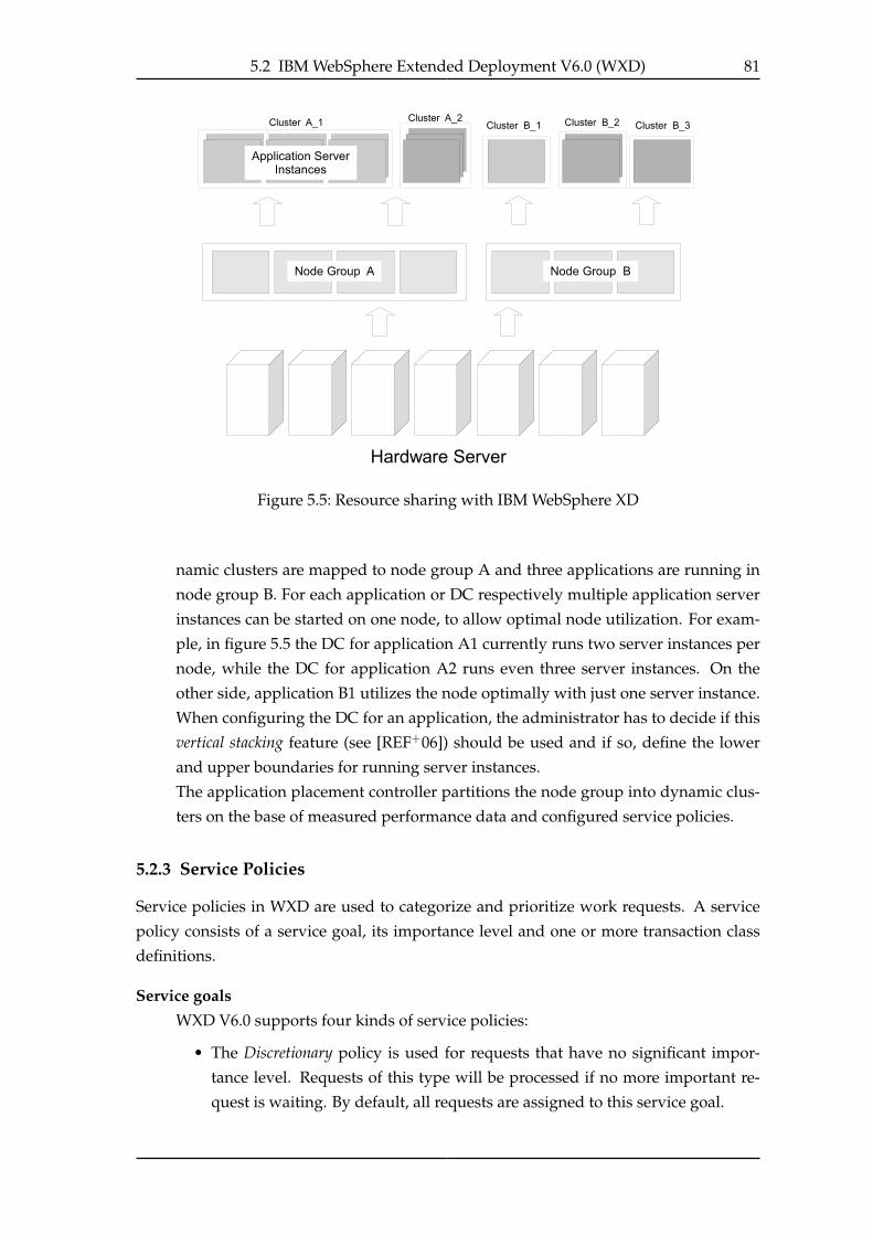
5.2 IBM WebSphere Extended Deployment V6.0 (WXD) 81
Figure 5.5: Resource sharing with IBM WebSphere XD
namic clusters are mapped to node group A and three applications are running in
node group B. For each application or DC respectively multiple application server
instances can be started on one node, to allow optimal node utilization. For exam-
ple, in figure 5.5 the DC for application A1 currently runs two server instances per
node, while the DC for application A2 runs even three server instances. On the
other side, application B1 utilizes the node optimally with just one server instance.
When configuring the DC for an application, the administrator has to decide if this
vertical stacking feature (see [REF+06]) should be used and if so, define the lower
and upper boundaries for running server instances.
The application placement controller partitions the node group into dynamic clus-
ters on the base of measured performance data and configured service policies.
5.2.3 Service Policies
Service policies in WXD are used to categorize and prioritize work requests. A service
policy consists of a service goal, its importance level and one or more transaction class
definitions.
Service goalsWXD V6.0 supports four kinds of service policies:
• The Discretionary policy is used for requests that have no significant impor-
tance level. Requests of this type will be processed if no more important re-
quest is waiting. By default, all requests are assigned to this service goal.
82 5 IBM Dynamic Infrastructure and WebSphere XD
• Requests with the service goal Average response time have a higher priority than
Discretionary. The response time can be specified in milliseconds and seconds
and has a target percentage of 90%, which means that at least 90% of the re-
quests must be answered within the given time.
• The service goal Percentile response time is similar to the Average response timeservice goal, but has a variable target percentage. To get a higher prioritization
than by Average response time, one can specify the target percentage for example
as 95%.
• The Queue wait time service policy is used for long-running applications. It can
be specified how long requests may wait in the incoming queue. If the limit is
reached, new servers are needed for request processing.
Importance levelIf the importance guarantees defined in by the service goals can not be satisfied, the
importance level of the service policy is used to prioritize the policies and the af-
fected requests. Policies can be classified into the seven importance levels: Lowest,
Lower, Low, Medium, High, Higher, Highest.
Transaction classesTransaction classes and work classes (see next section) are used to connect requests
to service policies and by this to service goals.
5.2.4 Work Classes
With the use of work classes, specific kinds of work belonging to a specific service policy
can be grouped together. This grouping can be based on URIs10, Web Service operations,
HTTP headers, Client or server IP address, port and host names. After a work class is
specified by creating its classification rules, a service policy can be assigned by assigning
a transaction class, which is mapped to the desired policy.
Figure 5.6 shows an overview of the request classification and prioritization process in
WXD. The used URI-based classification rules, defined in the working classes, are group-
ing requests from different J2EE modules. By mapping the working class to a transaction
class, the requests are mapped to a service policy and hence get a specific priority within
the system.
5.2.5 Creation of Service Policies and Work classes
Service policies, transaction classes and work classes can be specified in the AdministrativeConsole, the management web application of WXD. New policies and classifications can
be created and modified during runtime.
Like most of the administrative tasks in WXD, the creation of policies and classification
rules can be done with a Python-script on the command line. This should make it possible
10URI = Universal Resource Identifier

5.2 IBM WebSphere Extended Deployment V6.0 (WXD) 83
Figure 5.6: Request classification and prioritization in WebSphere XD (from [REF+06])
to connect the WXD configuration and management tasks with other components of the
EAM system.
5.2.6 Summary
With the central management and deployment capabilities, WXD offers a basis for fast
and flexible application provisioning and configuration. Although for the complete pro-
visioning of a server WXD has to leverage an external provisioning service, the on de-
mand deployment of CM services and the vertical stacking feature offer a flexible way to
create a dynamic infrastructure.
The ODR provides workload management functionalities with request categorization
and prioritization. To use the ODR for the EAM service, the provided service level objec-
tives have to be extended, to offer EAM specific SLOs, like archived emails per hour, or
maximum response time for standard search requests. First approaches by Kephart et. al
showed that WXD and Tivoli Intelligent Orchestrator (TIO) can be extended to use utility
functions (see section 2.8.1) for system optimization [KD07].

84 5 IBM Dynamic Infrastructure and WebSphere XD

85
6 Implementation
To evaluate the service-oriented concepts and the usability of WSRF and WSDM, Apache
Muse was chosen to implement a prototype. The advantages of using WSDM-compliant
services, the better theoretical assistance of implementing different service granularities
and the possibility of using a lightweight servlet-container for development and a ro-
bust J2EE application server for testing and production, make Apache Muse the better
candidate for the service runtime. An additional installation of GT4, to use only some
WSRF-comliant parts like the MDS, might be possible, but has not been tested yet.
The implemented prototype does only cover some of the aspects of the ingest process.
6.1 Infrastructure
6.1.1 Development Infrastructure
As Apache Muse runs on multiple J2EE containers, Apache Tomcat 5.51 and Jetty 62 were
used to enable lightweight and fast development. The jetty container was indirectly used
by an Apache Maven 23, to allow continuous development.
6.1.2 Target infrastructure
To test the prototype with realistic hardware, an IBM BladeCenter H located at the Uni-
versity of Stuttgart is available for the CMaaS project. The BladeCenter is equipped and
configured as follows:
• 2x JS21 (2x PowerPC, 4GB RAM)
– AIX® 5.3
– Lotus® Domino® Server
– IBM Content Manager 8.3 Fixpack 3
• 4x HS20 (4x Intel Xeon 3,2 GHz) + 8x HS21 (8x Intel Dual Core 2,3 GHz), each with
4GB RAM
– CentOS Linux4 as operating system
– Apache Tomcat 5.5
– partly installed: IBM WebSphere Application Server 6.1
1http://tomcat.apache.org/2http://jetty.mortbay.org/3http://maven.apache.org/4http://www.centos.org/
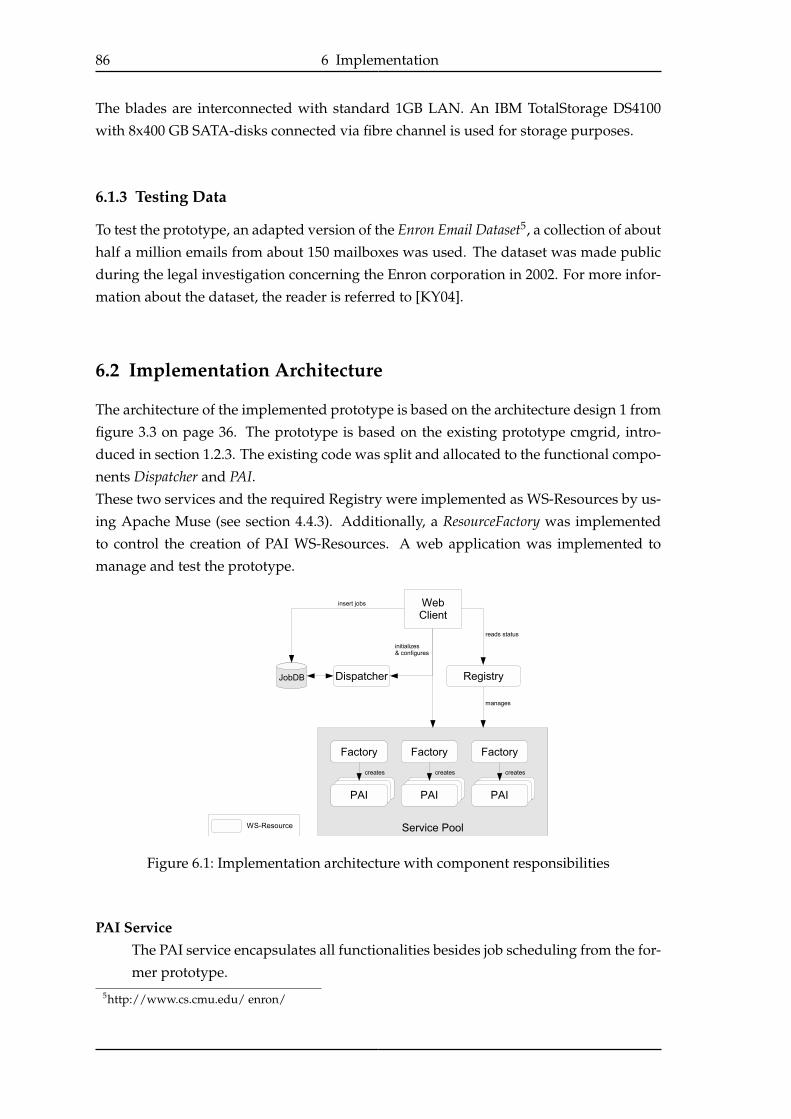
86 6 Implementation
The blades are interconnected with standard 1GB LAN. An IBM TotalStorage DS4100
with 8x400 GB SATA-disks connected via fibre channel is used for storage purposes.
6.1.3 Testing Data
To test the prototype, an adapted version of the Enron Email Dataset5, a collection of about
half a million emails from about 150 mailboxes was used. The dataset was made public
during the legal investigation concerning the Enron corporation in 2002. For more infor-
mation about the dataset, the reader is referred to [KY04].
6.2 Implementation Architecture
The architecture of the implemented prototype is based on the architecture design 1 from
figure 3.3 on page 36. The prototype is based on the existing prototype cmgrid, intro-
duced in section 1.2.3. The existing code was split and allocated to the functional compo-
nents Dispatcher and PAI.These two services and the required Registry were implemented as WS-Resources by us-
ing Apache Muse (see section 4.4.3). Additionally, a ResourceFactory was implemented
to control the creation of PAI WS-Resources. A web application was implemented to
manage and test the prototype.
Figure 6.1: Implementation architecture with component responsibilities
PAI ServiceThe PAI service encapsulates all functionalities besides job scheduling from the for-
mer prototype.5http://www.cs.cmu.edu/ enron/
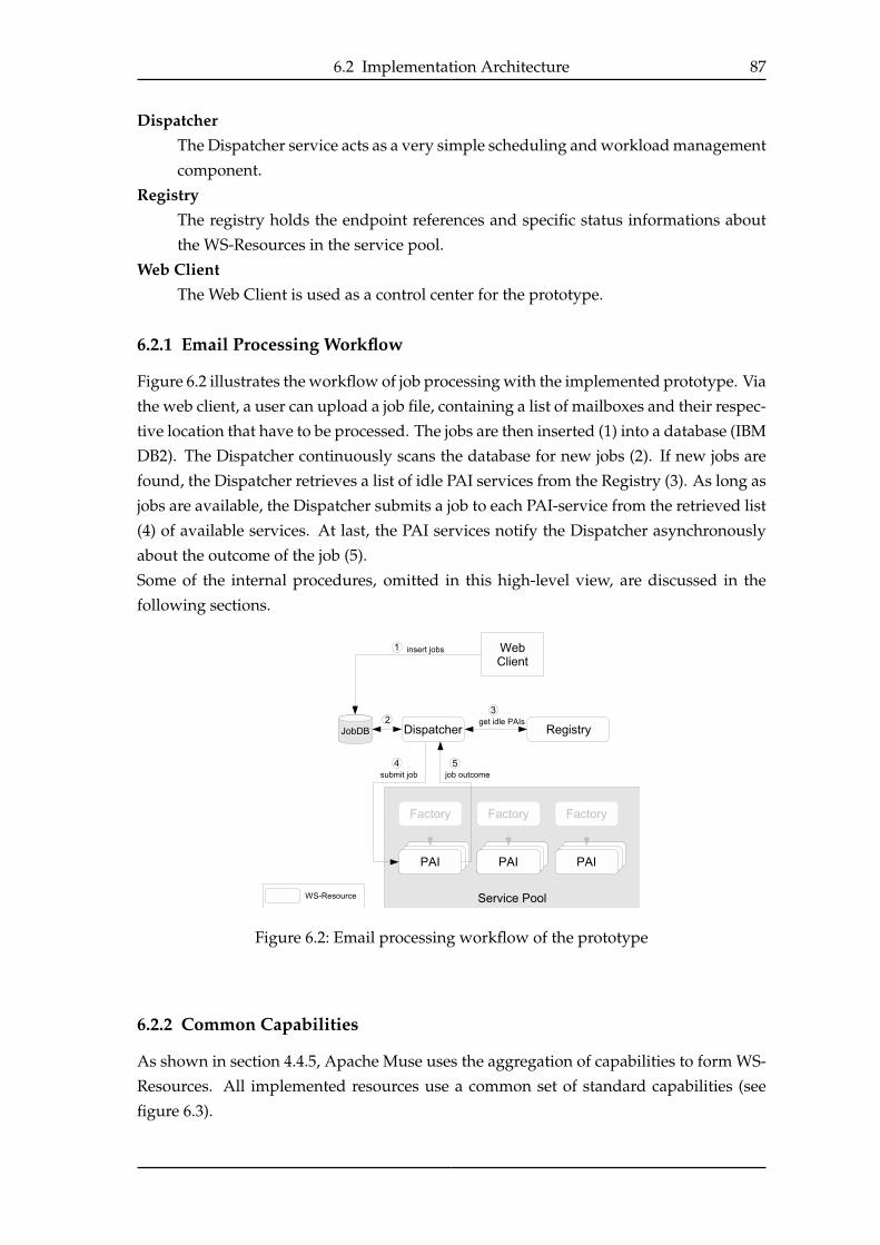
6.2 Implementation Architecture 87
DispatcherThe Dispatcher service acts as a very simple scheduling and workload management
component.
RegistryThe registry holds the endpoint references and specific status informations about
the WS-Resources in the service pool.
Web ClientThe Web Client is used as a control center for the prototype.
6.2.1 Email Processing Workflow
Figure 6.2 illustrates the workflow of job processing with the implemented prototype. Via
the web client, a user can upload a job file, containing a list of mailboxes and their respec-
tive location that have to be processed. The jobs are then inserted (1) into a database (IBM
DB2). The Dispatcher continuously scans the database for new jobs (2). If new jobs are
found, the Dispatcher retrieves a list of idle PAI services from the Registry (3). As long as
jobs are available, the Dispatcher submits a job to each PAI-service from the retrieved list
(4) of available services. At last, the PAI services notify the Dispatcher asynchronously
about the outcome of the job (5).
Some of the internal procedures, omitted in this high-level view, are discussed in the
following sections.
Figure 6.2: Email processing workflow of the prototype
6.2.2 Common Capabilities
As shown in section 4.4.5, Apache Muse uses the aggregation of capabilities to form WS-
Resources. All implemented resources use a common set of standard capabilities (see
figure 6.3).
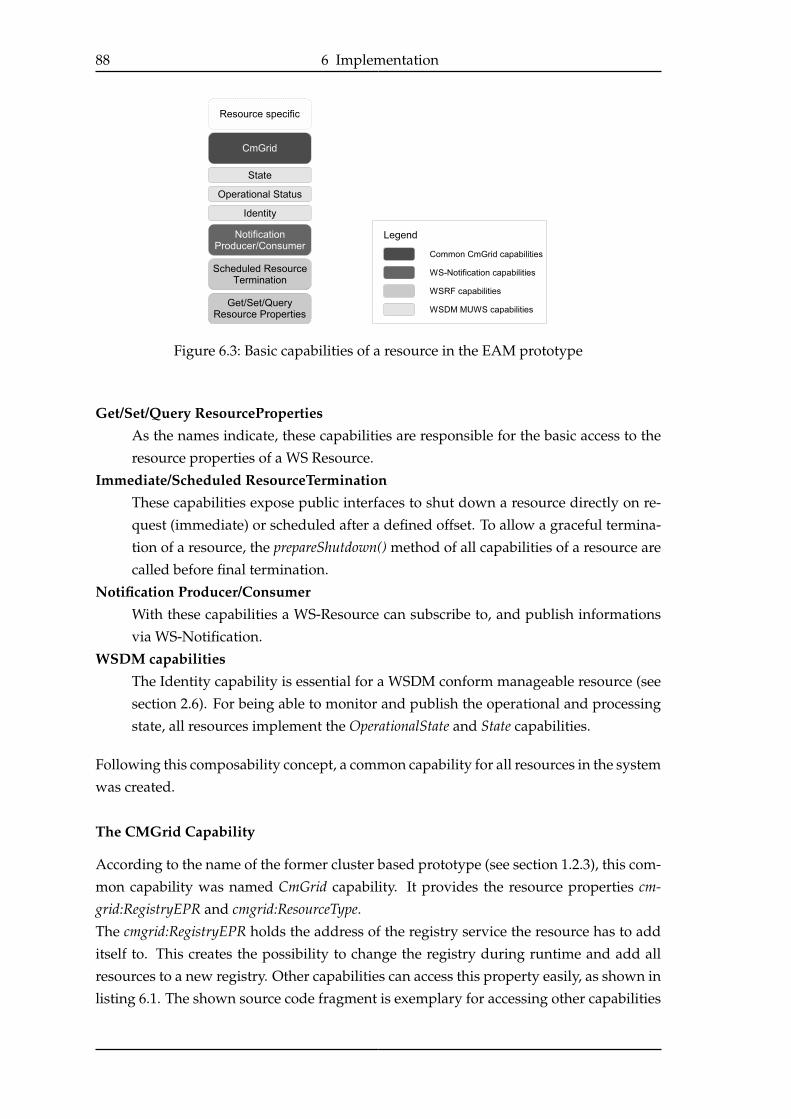
88 6 Implementation
Figure 6.3: Basic capabilities of a resource in the EAM prototype
Get/Set/Query ResourcePropertiesAs the names indicate, these capabilities are responsible for the basic access to the
resource properties of a WS Resource.
Immediate/Scheduled ResourceTerminationThese capabilities expose public interfaces to shut down a resource directly on re-
quest (immediate) or scheduled after a defined offset. To allow a graceful termina-
tion of a resource, the prepareShutdown() method of all capabilities of a resource are
called before final termination.
Notification Producer/ConsumerWith these capabilities a WS-Resource can subscribe to, and publish informations
via WS-Notification.
WSDM capabilitiesThe Identity capability is essential for a WSDM conform manageable resource (see
section 2.6). For being able to monitor and publish the operational and processing
state, all resources implement the OperationalState and State capabilities.
Following this composability concept, a common capability for all resources in the system
was created.
The CMGrid Capability
According to the name of the former cluster based prototype (see section 1.2.3), this com-
mon capability was named CmGrid capability. It provides the resource properties cm-grid:RegistryEPR and cmgrid:ResourceType.
The cmgrid:RegistryEPR holds the address of the registry service the resource has to add
itself to. This creates the possibility to change the registry during runtime and add all
resources to a new registry. Other capabilities can access this property easily, as shown in
listing 6.1. The shown source code fragment is exemplary for accessing other capabilities
6.3 Implementation Details 89
from the same resource.
Listing 6.1: Access to the CmGridCapability within other capabilities
1 //get the resource, the current capability belongs to
2 Resource thisResource = getResource();
3 //test, if the resource has the CmGrid capability
4 if(thisResource
5 .hasCapability(CmGridCapabilityInterface.NAMESPACE_URI))
6 {
7 //get access to the CMGrid capability
8 CmGridCapabilityInterface cmgridCap =
9 (CmGridCapabilityInterface) getResource()
10 .getCapability(CmGridCapabilityInterface.NAMESPACE_URI);
1112 //use the capability, e.g. get The registry endpoint reference (EPR)
13 EndpointReference epr =
14 new EndpointReference(cmgridCap.getRegistryEPR());
15 }
For further development, the use of a WSDM relationship property that describes the
association between a resource and its resource registry could be an option. The prop-
erty cmgrid:ResourceType represents the type of the resource (Dispatcher, Registry, Factory,
PAI). It is meant as a “helper property” through which type-based queries are possible at
the registry.
6.3 Implementation Details
Each component of the architecture is implemented as a single web application, to allow
stand-alone testing. The later combination of all resources and components into a single
or a few web applications can be done without much effort.
6.3.1 PAI Service
The PAI WS-Resource is the essential part of the prototype, as it contains all content man-
agement logic of the former prototype. Most of the configuration options of the former
prototype were managed by system properties during start-up. To enable a configuration
of the PAI service during runtime, some of the main configuration parameters are now ac-
cessible through resource properties. The most important properties are presented next.
Specific resource properties
NumberOfThreadsWith this property, the internal processing of a PAI service can be influenced. It
specifies with how many threads a PAI service is processing the emails of a job.
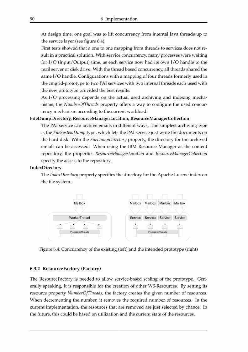
90 6 Implementation
At design time, one goal was to lift concurrency from internal Java threads up to
the service layer (see figure 6.4).
First tests showed that a one to one mapping from threads to services does not re-
sult in a practical solution. With service concurrency, many processes were waiting
for I/O (Input/Output) time, as each service now had its own I/O handle to the
mail server or disk drive. With the thread based concurrency, all threads shared the
same I/O handle. Configurations with a mapping of four threads formerly used in
the cmgrid-prototype to two PAI services with two internal threads each used with
the new prototype provided the best results.
As I/O processing depends on the actual used archiving and indexing mecha-
nisms, the NumberOfThreads property offers a way to configure the used concur-
rency mechanism according to the current workload.
FileDumpDirectory, ResourceManagerLocation, ResourceManagerCollectionThe PAI service can archive emails in different ways. The simplest archiving type
is the FileSystemDump type, which lets the PAI service just write the documents on
the hard disk. With the FileDumpDirectory property, the directory for the archived
emails can be accessed. When using the IBM Resource Manager as the content
repository, the properties ResourceManagerLocation and ResourceManagerCollectionspecify the access to the repository.
IndexDirectoryThe IndexDirectory property specifies the directory for the Apache Lucene index on
the file system.
Figure 6.4: Concurrency of the existing (left) and the intended prototype (right)
6.3.2 ResourceFactory (Factory)
The ResourceFactory is needed to allow service-based scaling of the prototype. Gen-
erally speaking, it is responsible for the creation of other WS-Resources. By setting its
resource property NumberOfThreads, the factory creates the given number of resources.
When decrementing the number, it removes the required number of resources. In the
current implementation, the resources that are removed are just selected by chance. In
the future, this could be based on utilization and the current state of the resources.
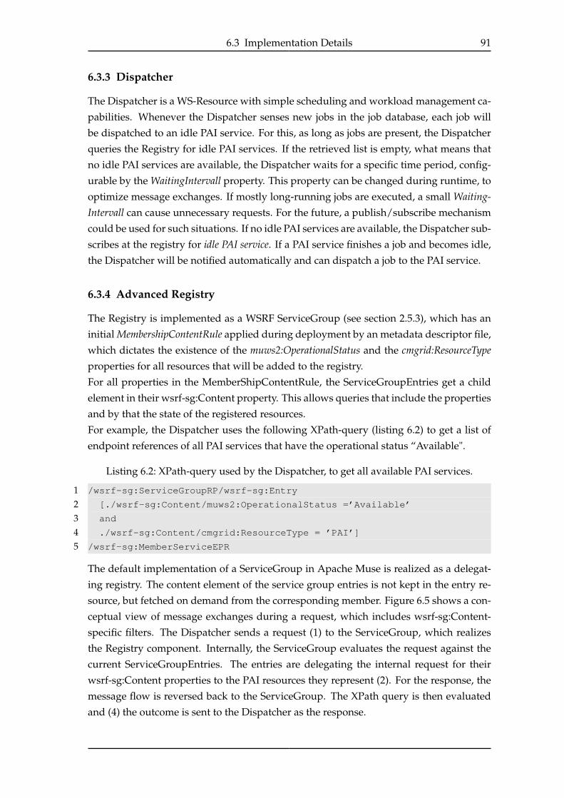
6.3 Implementation Details 91
6.3.3 Dispatcher
The Dispatcher is a WS-Resource with simple scheduling and workload management ca-
pabilities. Whenever the Dispatcher senses new jobs in the job database, each job will
be dispatched to an idle PAI service. For this, as long as jobs are present, the Dispatcher
queries the Registry for idle PAI services. If the retrieved list is empty, what means that
no idle PAI services are available, the Dispatcher waits for a specific time period, config-
urable by the WaitingIntervall property. This property can be changed during runtime, to
optimize message exchanges. If mostly long-running jobs are executed, a small Waiting-Intervall can cause unnecessary requests. For the future, a publish/subscribe mechanism
could be used for such situations. If no idle PAI services are available, the Dispatcher sub-
scribes at the registry for idle PAI service. If a PAI service finishes a job and becomes idle,
the Dispatcher will be notified automatically and can dispatch a job to the PAI service.
6.3.4 Advanced Registry
The Registry is implemented as a WSRF ServiceGroup (see section 2.5.3), which has an
initial MembershipContentRule applied during deployment by an metadata descriptor file,
which dictates the existence of the muws2:OperationalStatus and the cmgrid:ResourceTypeproperties for all resources that will be added to the registry.
For all properties in the MemberShipContentRule, the ServiceGroupEntries get a child
element in their wsrf-sg:Content property. This allows queries that include the properties
and by that the state of the registered resources.
For example, the Dispatcher uses the following XPath-query (listing 6.2) to get a list of
endpoint references of all PAI services that have the operational status “Available".
Listing 6.2: XPath-query used by the Dispatcher, to get all available PAI services.
1 /wsrf-sg:ServiceGroupRP/wsrf-sg:Entry
2 [./wsrf-sg:Content/muws2:OperationalStatus =’Available’
3 and
4 ./wsrf-sg:Content/cmgrid:ResourceType = ’PAI’]
5 /wsrf-sg:MemberServiceEPR
The default implementation of a ServiceGroup in Apache Muse is realized as a delegat-
ing registry. The content element of the service group entries is not kept in the entry re-
source, but fetched on demand from the corresponding member. Figure 6.5 shows a con-
ceptual view of message exchanges during a request, which includes wsrf-sg:Content-
specific filters. The Dispatcher sends a request (1) to the ServiceGroup, which realizes
the Registry component. Internally, the ServiceGroup evaluates the request against the
current ServiceGroupEntries. The entries are delegating the internal request for their
wsrf-sg:Content properties to the PAI resources they represent (2). For the response, the
message flow is reversed back to the ServiceGroup. The XPath query is then evaluated
and (4) the outcome is sent to the Dispatcher as the response.
92 6 Implementation
Figure 6.5: Standard WSRF ServiceGroup implementation of a Apache Muse
ServiceGroup Optimization
To minimize message exchanges during runtime, an advanced ServiceGroup implemen-
tation was developed for the prototype. Instead of delegating each request to the member
resources, the service group entries are keeping the state of the properties. The entries
subscribe at their corresponding member resources for property changes to be aware
of their current state. This approach assumes that the member resources implement
the WS-Notification Producer capability, which is needed for sending resource property
change notifications. To do the subscriptions, the service group entries implement the
WS-Notification Consumer capability.
To compare the two approaches of the ServiceGroup, the message exchanges during job
processing is shown in figure 6.6 for the default and in figure 6.7 for the advanced im-
plementation. The two figures show the Dispatcher (D), the Registry (R) and three PAI
services. When generalizing the number of PAI services toN , with the default implemen-
tation 4 + 2 × N messages are exchanged. With the advanced implementation, a static
number of only six messages are needed.
This example shows how effective the simple enhancement of the ServiceGroup is with
a growing number of PAI services and illustrates the need of effective communication
designs when deailing with a growing number of services.
It must be noted, that during initialization and termination of a PAI service, with the
default implementation, each time only two messages have to be exchanged for adding
to and removing the resource from the Registry. With the advanced implementation the
number of messages increases to four, as the subscribe and unsubscribe procedures cause
two messages at each time. As the lifetime of a resource is relatively long, the additional
two messages should be acceptable.

6.3 Implementation Details 93
Figure 6.6: Message exchange during job processing (default implementation)
Message flow (number of messages in brackets):
1. The dispatcher requests a list of idle PAI services. (1)
2. The request is delegated to the PAI services. (N)
3. The PAI service are responding. (N)
4. The response is sent to the Dispatcher. (1)
5. The Dispatcher submits a job to a PAI service. (1)
6. The PAI responses with the outcome. (1)
Figure 6.7: Message exchange during job processing (advanced implementation)
Message flow (number of messages in brackets):
1. The dispatcher requests a list of idle PAI services. (1)
2. The Registry evaluates the request internally and response directly. (1)
3. The Dispatcher submits a job to a PAI service. (1)
4. The PAI service notifies the Registry about its status (processing). (1)
5. After finishing the job, the PAI service notifies the Registry about its status (idle).(1)
6. The PAI service sends the job outcome to the Dispatcher. (1)
6.3.5 The Web Client
The implemented web client can be seen as a manual manager of the prototype, when
applying the autonomic architecture from figure 3.14 on page 50. The web client offers

94 6 Implementation
the following functionalities:
• For running tests, lists of actual archiving jobs can be loaded into the job database.
• Remote hosts can be initialized and integrated to the current configuration. Their
factory services are created and add themselves to the registry.
• PAI services can easily be created and destroyed by adjusting the NumberOfRe-sources property of a factory service.
• Users can use the web client to monitor the current processing of the PAI services.
The current OperationalStatus of each service is displayed and automatically up-
dated on changes. For that, the web client reads the current system state from the
registry.
• The Dispatcher can be started manually if new jobs have been loaded in the database.
By adjusting the WaitingIntervall property with the web client, the scheduling be-
haviour of the Dispatcher can be configured.
• To control the archiving and indexing process, the resource properties NumberOf-Threads, IndexDirectory and FileDumpDirectory of the PAI services can be changed.
Adapting one of these properties in the web client will update the properties for all
currently available PAI services.
All configuration tasks that are triggered by the web client are using the same WSRF /
WSDM compatible “effectors” an autonomic manager could use in the future.
6.4 Summary
The implemented prototype has proven the practical usage of WSRF and WSDM for
system management. The measurements made so far did not detect the overhead as a
slow-down for the overall performance. Although, statements on the actual influence of
SOAP-based communication overhead on a production system can not be given yet.
The gained flexibility through service-based scaling and configuration possibilities im-
proved the prototype’s overall manageability. PAI services can be added through the
system during runtime and are automatically used for email processing. Tests with run-
ning services on up to ten servers have shown that possible performance bottlenecks like
the registry or the dispatcher performed well and failure-free.
The experiences of the development process affirmed the results from the theoretical eval-
uation of Apache Muse. The composability concept allowed the independent develop-
ment of capabilities and a later combination to a single WS-Resource.
Significant "ingest-performance" measurements have not been made so far, as a meaning-
ful and realistic data set with attachments is needed first. Although, first performance
comparisons with the existing cluster-based cmgrid-prototype by using the enron dataset,showed that the service-oriented prototype performs comparably.
95
7 Conclusions and Further Lines ofInvestigation
To cope with the rapidly growing challenges of Content Management, a number of ac-
tions must be taken to create a competing new Content Management System. A service-
oriented, automated design poses various challenges for the underlying infrastructure.
For this thesis, the requirements were layered into three categories. The service runtimehas to provide basic SOA and manageability functionalities. For the non-trivial Content
Management services, classical stateless Web Services are not sufficient. Stateful services
with life cycle capabilities are needed to manage scalability and fine-grained optimization
tasks. The category of Resource Management (RM) combines requirements which focus on
the handling of resource-based functionalities. Key features of a required RM system
are resource allocation and resource provisioning. By providing customized access to a
resource model, customers, administrators or computer programs can get an overview
of currently used resources or services. The provisioning service allows to install, con-
figure and start arbitrary applications on newly allocated resources. Together with a
broad range of monitoring data, the RM system offers a main piece of system knowl-
edge, which is needed for the requirements category stated as System Automation. This
category concentrates on the combination of offered information by the service runtime
and RM system to form a knowledge base for a kind of autonomic manager. This au-
tonomic manager has to be configured with detailed service policies, which control the
system behaviour. System automation is the field were a lot of research has to be done,
as SLAs have to be transformed into service policies automatically. To create effective
service policies, the effects of possible configuration actions like the provisioning of new
resources to a running EAM system are needed.
For this thesis the grid-related standards WSRF and WSDM, in addition to their open
source implementations along with the commercial solutions IBM Dynamic Infrastructure(IDI) and IBM WebSphere Extended Deployment (WXD), were evaluated against the pre-
sented requirements.
With the Web Services Resource Framework (WSRF) and the Web Services Distributed Manage-ment (WSDM), two powerful specifications exist that can offer the functionalities needed
for a service runtime. By taking WSRF as a requirement, the Globus Tookit 4 and ApacheMuse were compared and evaluated. With Apache Muse, a lightweight implementa-
tion was chosen, which offers a flexible way to create different service granularities.
With being runnable in standardized J2EE containers, the advantages of robust and well-
known application servers like the IBM WebSphere Application Server can be used. By
using WSDM features like metrics or relationships, the base for a manageable EAM sys-

96 7 Conclusions and Further Lines of Investigation
tem needed for later system automation is given. The implementation of a prototype by
using Apache Muse has proven that for management and orchestrating functionalities
WSRF / WSDM-based Web Services are a practical and comfortable way. Compared to
the previous cluster-based prototype, the new SOA-based implementation competes re-
garding performance and scalability, while offering extended features for configuration
and manageability.
IBM Dynamic Infrastructure (IDI) and IBM WebSphere XD (WXD) can cover a lot of the
remaining requirements for resource management and system automation. By having a
central point of control with the IDI management console, all administrative tasks start-
ing with offering an EAM service to customers, over initiating a customized EAM in-
stance based on a customer’s subscription, to manual management tasks during runtime
and the final service termination can be handled. A detailed resource model can be cre-
ated, to manage resource allocations and metering tasks.
WXD provides a powerful runtime environment for the CM services. By combining all
application servers allocated for an EAM instance to a dynamic cluster (see section 5.2),
management tasks like application installation and configuration can be processed at a
central point. The feature of vertical stacking can improve the overall resource utilization
and can be configured to run automatically. With its integrated monitoring capabilities,
WXD provides a lot of the needed monitoring functionalities. As a first step to system
automation the optimization features by the On Demand Router (ODR) could be used. Al-
though to handle the required high-level service level objectives for EAM, a lot of work
has to be done to adapt the features for the EAM system.
Figure 7.1 shows a possible composition of the infrastructure for the EAM system out
of the evaluated software systems. The WebSphere Application Server (under control of
WXD) builds the basis for the service runtime. Apache Muse, with its WSRF and WSDM
conform Web Service stack, provides a comfortable solution for the service runtime. The
monitoring aspect of resource management is not completely covered by the evaluated
products. Application-based monitoring can be implemented with Muse, although the
scalability aspect of WSDM-based monitoring has to be examined. WXD offers low-level
monitoring functionalities for the WebSphere servers. None of the products can combine
the application and system-based monitoring data into one data stream. IDI covers most
of the other necessary resource management functionalities. Exemplarily the parts Re-source Model and Provisioning Service are illustrated in figure 7.1. Most functionalities are
missing in the automation category. SLA management is only partly covered by IDI and
WXD. IDI offers event-based metering and accounting capabilities. The SLA functionali-
ties of WXD may be expandable to meet the EAM requirements. The same applies for the
policy-based optimization rules of WXD. Nevertheless, a lot of research has to be done
regarding system automation.

97
Figure 7.1: Possible composition of the EAM infrastructure
Further Lines of Investigation
This thesis has shown that with existing products most of the stated requirements can
be covered. The implemented prototype has proven the usability and manageability of a
WSDM based service runtime. Figure 7.1 indicates a growing ability of autonomy when
traversing the functionality stack from the service runtime up to system automation. As
system automation depends on a functional resource management system, the further
research and implementation steps should follow this "stack of requirements".
Following this approach, the next steps for the CMaaS team in Hamburg would be to
analyze how IDI can be used with the existing prototype. Which exact actions must be
taken by an initial order? How can the actual provisioning tasks be realized? As men-
tioned in section 3.3.2, to enable system automation, an integrated view of application
and low-level monitoring data must be provided. The monitoring and discovery service of
GT4 (section 4.4.8) or the WSDM data collector engine for Tivoli Monitoring (see section
4.4.8) might be a way for the necessary integration.
Further steps include the management of Service Level Agreements. Both IDI and WXD
offer some functionalities to support SLAs. Standards like WS-Agreement [ACD+06] or
WSLA [KL03] should be examined as an alternative.
The most challenging task for further research will be to handle automated system opti-
mization. For this step all necessary system information has to be integrated and acces-
sible as the knowledge base for a system-wide autonomic manager. Before being able to
write practical system policies, the effects of system modifications like provisioning tasks
on system behaviour have to be examined by experiment.

98 7 Conclusions and Further Lines of Investigation

List of Abbreviations 99
List of Abbreviations
API . . . . . . . . . . . . . Application Programming Interface
ASP . . . . . . . . . . . . . Application Service Provider
B2B . . . . . . . . . . . . . Business-to-Business
CMaaS . . . . . . . . . . Content Management as a Service
CMS . . . . . . . . . . . . Content Management System
EAM . . . . . . . . . . . . Email Archiving and Management
EAMS . . . . . . . . . . Email Archiving and Management System
ECM . . . . . . . . . . . . Enterprise Content Management
ECMS . . . . . . . . . . . Enterprise Content Management System
EPR . . . . . . . . . . . . . Endpoint Reference
ESB . . . . . . . . . . . . . Enterprise Service Bus
GDPdU . . . . . . . . . Grundsätze zum Datenzugriff
und zur Prüfbarkeit digitaler Unterlagen
GT4 . . . . . . . . . . . . . Globus Toolkit 4
IDI . . . . . . . . . . . . . . IBM Dynamic Infrastructure
J2EE . . . . . . . . . . . . Java 2 Enterprise Edition
J2ME . . . . . . . . . . . Java 2 Platform, Micro Edition
JNDI . . . . . . . . . . . . Java Naming and Directory Interface
MOWS . . . . . . . . . Management of Web Services
MUWS . . . . . . . . . . Management using Web Services
OASIS . . . . . . . . . . Organization for the Advancement
of Structured Information Standards
ODR . . . . . . . . . . . . On Demand Router
ODS . . . . . . . . . . . . On Demand Service
OGSA . . . . . . . . . . Open Grid Services Architecture
OGSI . . . . . . . . . . . Open Grid Services Infrastructure
OSGi . . . . . . . . . . . . Open Service Gateway initiative
PAI . . . . . . . . . . . . . Parsing, Archiving, Indexing
QoS . . . . . . . . . . . . . Quality of Service
RDBMS . . . . . . . . . Relational Database Management System
RMS . . . . . . . . . . . . Resource Management System
SaaS . . . . . . . . . . . . Software as a Service
SAX . . . . . . . . . . . . Simple API for XML
SLA . . . . . . . . . . . . . Service Level Agreement
SOA . . . . . . . . . . . . Service-Oriented Architecture
SOAP . . . . . . . . . . . An obsolute name since version 1.2 of the SOAP standard
SOX . . . . . . . . . . . . Sarbanes-Oxley Act

100 List of Abbreviations
StAX . . . . . . . . . . . . Streaming API for XML
WAR . . . . . . . . . . . . Web Application Archive
WSDL . . . . . . . . . . Web Services Description Language
WSDM . . . . . . . . . . Web Services Management Framework
WSRF . . . . . . . . . . . Web Services Resource Framework
WXD . . . . . . . . . . . IBM WebSphere Extended Deployment
XML . . . . . . . . . . . . Extensible Markup Language
XPath . . . . . . . . . . . XML Path Language

101
List of Figures
1.1 Simplified architecture of the cmgrid prototype . . . . . . . . . . . . . . . . 4
2.1 Evolution of Enterprise IT Architecture [FT05] . . . . . . . . . . . . . . . . 9
2.2 Roles in a service-oriented architecture . . . . . . . . . . . . . . . . . . . . . 11
2.3 Popular message exchange patterns in SOA designs . . . . . . . . . . . . . 12
2.4 The OGSA conceptual view . . . . . . . . . . . . . . . . . . . . . . . . . . . 15
2.5 How OGSA fits in the middleware stack . . . . . . . . . . . . . . . . . . . . 16
2.6 The ShoppingCartService . . . . . . . . . . . . . . . . . . . . . . . . . . . . 18
2.7 The implied resource pattern . . . . . . . . . . . . . . . . . . . . . . . . . . 20
2.8 ServiceGroup . . . . . . . . . . . . . . . . . . . . . . . . . . . . . . . . . . . 22
2.9 The concept of a manageable resource in WSDM . . . . . . . . . . . . . . . 23
2.10 Composability (from [TC06b]) . . . . . . . . . . . . . . . . . . . . . . . . . . 24
2.11 MAPE-loop . . . . . . . . . . . . . . . . . . . . . . . . . . . . . . . . . . . . 29
2.12 System state transitions . . . . . . . . . . . . . . . . . . . . . . . . . . . . . . 29
3.1 Comparison of business objects for the dedicated server and EAM service
business models. . . . . . . . . . . . . . . . . . . . . . . . . . . . . . . . . . 32
3.2 The life cycle phases of an EAM service . . . . . . . . . . . . . . . . . . . . 32
3.3 A service-oriented design for the EAM system . . . . . . . . . . . . . . . . 36
3.4 Structure of an EAM service . . . . . . . . . . . . . . . . . . . . . . . . . . . 37
3.5 Resource allocation by the data center manager . . . . . . . . . . . . . . . . 38
3.6 Use Case 1 - System scale-out . . . . . . . . . . . . . . . . . . . . . . . . . . 40
3.7 Use Case 2 - System scale-in . . . . . . . . . . . . . . . . . . . . . . . . . . . 41
3.8 Autonomic email archiving infrastructure concept . . . . . . . . . . . . . . 42
3.9 Service based system reconfiguration . . . . . . . . . . . . . . . . . . . . . . 43
3.10 The three perspectives of resource management . . . . . . . . . . . . . . . 45
3.11 Classification of QoS metrics . . . . . . . . . . . . . . . . . . . . . . . . . . . 46
3.12 Dependencies of application-wide availability on the internal resources . . 48
3.13 Autonomic computing reference architecture . . . . . . . . . . . . . . . . . 49
3.14 Hierarchical autonomic architecture of the EAM service . . . . . . . . . . . 50
4.1 The WS-Resource Factory Pattern message flow . . . . . . . . . . . . . . . . 55
4.2 State diagram for the operational state of a resource . . . . . . . . . . . . . 59
4.3 Simplified resource model . . . . . . . . . . . . . . . . . . . . . . . . . . . . 61
4.4 Globus Toolkit 4 architecture overview . . . . . . . . . . . . . . . . . . . . . 63
4.5 Globus Toolkit 4 programming model . . . . . . . . . . . . . . . . . . . . . 66
4.6 Apache Muse Programming Model . . . . . . . . . . . . . . . . . . . . . . . 67
102 List of Figures
4.7 Comparison of GT4 and Apache Muse . . . . . . . . . . . . . . . . . . . . . 72
5.1 Offering and subscription in the concept of an on demand service . . . . . 73
5.2 The IBM DI Resource Model . . . . . . . . . . . . . . . . . . . . . . . . . . . 75
5.3 The life cycle of an ODS in IDI . . . . . . . . . . . . . . . . . . . . . . . . . . 76
5.4 Recommended topology for an WXD operational environment . . . . . . . 79
5.5 Resource sharing with IBM WebSphere XD . . . . . . . . . . . . . . . . . . 81
5.6 Request classification and prioritization in WebSphere XD . . . . . . . . . 83
6.1 Implementation architecture . . . . . . . . . . . . . . . . . . . . . . . . . . . 86
6.2 Email processing workflow of the prototype . . . . . . . . . . . . . . . . . 87
6.3 Basic capabilities of a resource in the EAM prototype . . . . . . . . . . . . 88
6.4 Concurrency of the existing and the intended prototype . . . . . . . . . . . 90
6.5 Simple delegating Registry . . . . . . . . . . . . . . . . . . . . . . . . . . . . 92
6.6 Message exchange during job processing (default implementation) . . . . 93
6.7 Message exchange during job processing (advanced implementation) . . . 93
7.1 Possible composition of the EAM infrastructure . . . . . . . . . . . . . . . 97

103
Listings
2.1 Porttypes and operation for the CartService with standard Web Services . 18
2.2 WSCreateCartRequest with a non-WSRF service . . . . . . . . . . . . . . . 19
2.3 Corresponding “WSCreateCartResponse" to listing 2.2 . . . . . . . . . . . 19
2.4 WSRF SOAP-Message . . . . . . . . . . . . . . . . . . . . . . . . . . . . . . 20
2.5 Content of a shopping cart realized as ResourceProperties . . . . . . . . . 21
2.6 Referencing a metadata descriptor for a specific portType . . . . . . . . . . 22
2.7 Declaration of the property printedPages as a metric by the addition of
metadata . . . . . . . . . . . . . . . . . . . . . . . . . . . . . . . . . . . . . . 25
4.1 Representing state in WSRF . . . . . . . . . . . . . . . . . . . . . . . . . . . 54
4.2 Destroying a WS-Resource through a wsrl-destroy message . . . . . . . . 55
4.3 MembershipContentRule which restricts the registry to WS-Resources with
the OperationalStatus property . . . . . . . . . . . . . . . . . . . . . . . . . 56
4.4 Subscription message for resource changes. . . . . . . . . . . . . . . . . . . 57
4.5 Sample resource change notification for a subscription as in listing 4.4 . . 58
4.6 Construction of a state taxonomy . . . . . . . . . . . . . . . . . . . . . . . . 59
4.7 The use of the WSDM MUWS RelationshipType to create a resource model 60
4.8 "Pseudo-code” for a possible usage of the composability concept to realize
different service granularities . . . . . . . . . . . . . . . . . . . . . . . . . . 67
4.9 A sample WSDD file for a WS-Resource in GT4 . . . . . . . . . . . . . . . . 68
4.10 A JNDI deployment file for a simple WS-Resource . . . . . . . . . . . . . . 69
4.11 A sample Apache Muse deployment descriptor for a WS-Resource . . . . 70
6.1 Access to the CmGridCapability within other capabilities . . . . . . . . . . 89
6.2 XPath-query used by the Dispatcher, to get all available PAI services. . . . 91

104 Listings

105
Bibliography
[ACD+06] Alain Andrieux, Karl Czajkowski, Asit Dan, Kate Keahey, Heiko Ludwig,
Toshiyuki Nakata, Jim Pruyne, John Rofrano, Steve Tuecke, and Ming Xu.
Web Services Agreement Specification. https://forge.gridforum.org, 9 2006.
Draft document.
[ALR01] A. Avizienis, J. Laprie, and B. Randell. Fundamental Concepts of Depend-
ability. Research Report N01145, LAAS-CNRS, April 2001., 4 2001.
[Ban06] Tim Banks. Web Services Resource Framework (WSRF) - Primer v1.2. Inter-
net, 5 2006. Committee Draft 02 - 23 May 2006.
[BCC+04] Don Box, Erik Christensen, Francisco Curbera, Donald Ferguson, Jeffrey
Frey, Marc Hadley, Chris Kaler, David Langworthy, Frank Leymann, Brad
Lovering, Steve Lucco, Steve Millet, Nirmal Mukhi, Mark Nottingham,
David Orchard, John Shewchuk, Eugène Sindambiwe, Tony Storey, San-
jiva Weerawarana, and Steve Winkler. Web Services Addressing (WS-
Addressing). Technical report, The World Wide Web Consortium (W3C),
2004. W3C Member Submission 10 August 2004.
[BDP+03] T. Banks, A. Djaoui, S. Parastatids, A. Mani, S. Tuecke, K. Czajkowski, I. Fos-
ter, J. Frey, S. Graham, C. Kesselman, T. Maguire, T. Sandholm, D. Snelling,
and P. Vanderbilt. Open Grid Services Infrastructure (OGSI) Version 1.0.
http://www.ggf.org/documents/GFD.15.pdf, 6 2003.
[BEF+] Keith Ballinger, David Ehnebuske, Christopher Ferris, Martin Gudgin,
Canyang Kevin Liu, Mark Nottingham, and Prasad Yendluri. Basic Profile
Version 1.1. http://www.ws-i.org.
[Biß07] Malte Biß. Componentization and Orchestration of Content Management
Services. Master’s thesis, Universität Hamburg, 2007.
[BJM+05] Özalp Babaoglu, Márk Jelasity, Alberto Montresor, Christof Fetzer, Stefano
Leonardi, Aad P. A. van Moorsel, and Maarten van Steen, editors. Self-starProperties in Complex Information Systems, Conceptual and Practical Foundations[the book is a result of a workshop at Bertinoro, Italy, Summer 2004], volume 3460
of Lecture Notes in Computer Science. Springer, 2005.
[Bre07] Gerd Breiter. Utility Computing als integraler Bestandteil der serviceorientiertenArchitektur, chapter 3.3, pages 78–100. In Kircher [KKP+07], 2007.
106 Bibliography
[CBC+05] Catherine H. Crawford, G. Paul Bate, Luba Cherbakov, Kerrie Holley, and
Charles Tsocanos. Toward an on demand service-oriented architecture. IBMSystems Journal, 44(1):81–108, 2005.
[CFF+04] Karl Czajkowski, Donald F Ferguson, Ian Foster, Jeffrey Frey, Steve Graham,
Igor Sedukhin, David Snelling, Steve Tuecke, and William Vambenepe. The
WS-Resource Framework - Version 1.0, 3 2004. Initial draft release from
03/05/2004.
[CGB02] Kenneth Chiu, Madhusudhan Govindaraju, and Randall Bramley. Investi-
gating the Limits of SOAP Performance for Scientific Computing. In HPDC,
pages 246–254. IEEE Computer Society, 2002.
[Coh06] Frank Cohen. FastSOA: The way to use native XML technology to achieve Ser-vice Oriented Architecture governance, scalability, and performance (The MorganKaufmann Series in Data Management Systems). Morgan Kaufmann Publishers
Inc., San Francisco, CA, USA, 2006.
[CYZ+06] Shiping Chen, Bo Yan, John Zic, Ren Liu, and Alex Ng. Evaluation and
Modeling of Web Services Performance. icws, 0:437–444, 2006.
[FK99] Ian Foster and Carl Kesselman. The Grid: Blueprint for a New ComputingInfrastructure. Morgan Kaufmann Publishers Inc., San Francisco, CA, USA,
1999.
[FKNT02] Ian Foster, Carl Kesselman, Jeffrey M. Nick, and Steven Tuecke. The Physi-
ology of the Grid: An Open Grid Services Architecture for Distributed Sys-
tems Integration, 2002.
[FKS+05] I. Foster, H. Kishimoto, A. Savva, D. Berry, A. Djaoui, A. Grimshaw, B. Horn,
F. Maciel, F. Siebenlist, R. Subramaniam, J. Treadwell, and J. Von Reich. The
Open Grid Services Architecture, Version 1.0, 1 2005.
[FKS+06] I. Foster, H. Kishimoto, A. Savva, D. Berry, A. Grimshaw, B. Horn, F. Maciel,
F. Siebenlist, R. Subramaniam, J. Treadwell, and J. Von Reich. The Open Grid
Services Architecture, Version 1.5. Technical report, Global Grid Forum, 7
2006.
[FKT01] Ian T. Foster, Carl Kesselman, and Steven Tuecke. The Anatomy of the Grid
- Enabling Scalable Virtual Organizations. International J. Supercomputer Ap-plications, 15(3), cs.AR/0103025, 2001.
[FMS06] Ian T. Foster, T. Maguire, and D. Snelling. OGSA WSRF Basic Profile 1.0.
http://www.ggf.org/documents/GFD.72.pdf, 5 2006.
[Fos02] Ian T. Foster. What is the Grid? A Three Point Checklist. GRIDToday, 7 2002.

Bibliography 107
[Fos05] Ian T. Foster. A Globus Primer Or, Everything You Wanted to Know about
Globus, but Were Afraid To Ask Describing Globus Toolkit Version 4, 5 2005.
[FT05] Ian T. Foster and Steven Tuecke. Describing the elephant: The different faces
of IT as service. ACM Queue, 3(6):26–29, 2005.
[GC03] Alan G. Ganek and Thomas A. Corbi. The dawning of the autonomic com-
puting era. IBM Systems Journal, 42(1):5–18, 2003.
[GHM06] Steve Graham, David Hull, and Bryan Murray. Web Services Base Notifica-
tion 1.3 (WS-BaseNotification), 10 2006. OASIS Standard, 1 October 2006.
[Gro05] The Radicati Group. Taming the Growth of Email - An ROI Analysis.
http://www.radicati.com, 3 2005. White Paper by The Radicati Group, Inc.
[GSC+04] Madhusudhan Govindaraju, Aleksander Slominski, Kenneth Chiu, Pu Liu,
Robert van Engelen, and Michael J. Lewis. Toward Characterizing the Per-
formance of SOAP Toolkits. In Rajkumar Buyya, editor, GRID, pages 365–
372. IEEE Computer Society, 2004.
[GSM+01] Klaus Götzer, Udo Schneiderath, Berthold Maier, Wolfgang Boehmelt, and
Torsten Komke. Dokumenten-Management : Informationen im Unternehmeneffizient nutzen. dpunkt.verlag GmbH, 2001.
[HGS+05] Michael R. Head, Madhusudhan Govindaraju, Aleksander Slominski,
Pu Liu, Nayef Abu-Ghazaleh, Robert van Engelen, Kenneth Chiu, and
Michael J. Lewis. A Benchmark Suite for SOAP-based Communication in
Grid Web Services. In SC, page 19. IEEE Computer Society, 2005.
[HGvEZ06] Michael R. Head, Madhusudhan Govindaraju, Robert van Engelen, and Wei
Zhang. Benchmarking XML processors for applications in grid web services.
In SC ’06: Proceedings of the 2006 ACM/IEEE conference on Supercomputing,
page 121, New York, NY, USA, 2006. ACM Press.
[HKC+06] Salim Hariri, Bithika Khargharia, Huoping Chen, Jingmei Yang, Yeliang
Zhang, Manish Parashar, and Hua Liu. The Autonomic Computing
Paradigm. Cluster Computing, 9(1):5–17, 2006.
[IBM06] IBM. An architectural blueprint for autonomic computing. http://www-
03.ibm.com/autonomic/, 6 2006. Fourth Edition.
[KC03] Jeffrey O. Kephart and David M. Chess. The Vision of Autonomic Comput-
ing. IEEE Computer, 36(1):41–50, 2003.
[KD07] Jeffrey O. Kephart and Rajarshi Das. Achieving Self-Management via Utility
Functions. IEEE Internet Computing, 11(1):40–48, 2007.
108 Bibliography
[KKP+07] Dieter König, Matthias Kloppmann, Gerhard Pfau, Michael Scheible,
Werner Ederer, Gerd Breiter, Boas Betzler, Jürgen Schneider, and Oliver Au-
genstein. IT - Technologien, Lösungen, Innovationen. Springer Berlin Heidel-
berg, 2007.
[KL03] Alexander Keller and Heiko Ludwig. The WSLA Framework: Specifying
and Monitoring Service Level Agreements for Web Services. Technical Re-
port 1, 2003.
[KW04] Jeffrey O. Kephart and William E. Walsh. An Artificial Intelligence Perspec-
tive on Autonomic Computing Policies. In POLICY, pages 3–12. IEEE Com-
puter Society, 2004.
[KY04] Bryan Klimt and Yiming Yang. Introducing the Enron Corpus. In CEAS,
2004.
[LB05] Maozhen Li and Mark Baker. The grid core technologies. John Wiley & Sons,
2005.
[MSB06] Tom Maguire, David Snelling, and Tim Banks. Web Services Service Group
1.2, 4 2006. OASIS Standard, 1 April 2006.
[MWE06] Bryan Murray, Kirk Wilson, and Mark Ellison. Web Services Distributed
Management: MUWS Primer. http://www.oasis-open.org, 2 2006. Com-
mittee Draft, February 24, 2006.
[MWM05] Cataldo Mega, Frank Wagner, and Bernhard Mitschang. From Content Man-
agement to Enterprise Content Management. In Gottfried Vossen, Frank
Leymann, Peter C. Lockemann, and Wolffried Stucky, editors, BTW, vol-
ume 65 of LNI, pages 596–613. GI, 2005.
[NL04] Eric Newcomer and Greg Lomow. Understanding SOA with Web Services.
Independent Technology Guides. Addison-Wesley Professional, 2004.
[OAS] Organization for the Advancement of Structured Information Standards.
http://www.oasis-open.org. visited on 02/08/2007.
[OAS06a] OASIS Group. OASIS Web Services Notification Standard 1.3.
http://www.oasis-open.org/, October 2006. Set of the follwing Speci-
fications: WS-BaseNotification 1.3, WS-BrokeredNotification 1.3,WS-Topics
1.3.
[OAS06b] OASIS Group. OASIS Web Services Resource Framework Standard
1.2, 2006. Set of the following specifications: WS-Resource, WS-
ResourceProperties (WSRF-RP), WS-ResourceLifetime (WSRF-RL), WS-
ServiceGroup (WSRF-SG), WS-BaseFaults (WSRF-BF).

Bibliography 109
[PHE+06] Srinath Perera, Chathura Herath, Jaliya Ekanayake, Eran Chinthaka, Ajith
Ranabahu, Deepal Jayasinghe, Sanjiva Weerawarana, and Glen Daniels.
Axis2, Middleware for Next Generation Web Services. In ICWS, pages 833–
840. IEEE Computer Society, 2006.
[PW05] Pawel Plaszczak and Richard Wellner. Grid Computing: The Savvy Manager’sGuide. Morgan Kaufmann Publishers Inc., San Francisco, CA, USA, 2005.
[REF+06] Birgit Roehm, Thomas Erker, Carrie Finneran, Vijay Mann, Kwan-Ming
Wan, and Peter Wiedeking. Using WebSphere Extended Deployment V6.0 ToBuild an On Demand Production Environment. IBM Redbooks, 2006.
[SB06] Latha Srinivasan and Tim Banks. Web Services Resource Lifetime 1.2 (WS-
ResourceLifetime), 4 2006. OASIS Standard, 1 April 2006.
[SCD+97] Bikash Sabata, Saurav Chatterjee, Michael Davis, Jaroslaw J. Sydir, and
Thomas F. Lawrence. Taxonomy for QoS specifications. In Workshop onObject-Oriented Real-Time Dependable Systems (WORDS). IEEE Computer So-
ciety, 1997.
[Sch06] Sergej Schütz. Indexierung von E-Mail-Archiven mit hohem Nachrichte-
naufkommen. Diplomarbeit, Universität Stuttgart - Institut für parallele
und verteilte Systeme, 6 2006.
[SDt06] of The Open Group SOA Definition team, of the SOA Working Group. Def-
inition of SOA, 6 2006. Version 1.1.
[SG05] Akhil Sahai and Sven Graupner. Web Services in the Enterprise. Concepts, Stan-dards, Solutions, and Management. Springer-Verlag GmbH, 2005.
[Sot] Borja Sotomayor. The Globus Toolkit 4 Programmer’s Tutorial. University of
Chicago Department of Computer Science.
[Str04] John C. Strassner. Policy-Based Network Management Sulutions for the NextGeneration. Morgan Kaufmann Publishers, 2004.
[TC06a] OASIS Web Services Distributed Management TC. Web Services Distributed
Management: Management of Web Services (WSDM-MOWS) 1.1, 10 2006.
OASIS Standard, 01 August 2006.
[TC06b] OASIS Web Services Distributed Management TC. Web Services Distributed
Management: Management Using Web Services (MUWS 1.1) Part 1, 8 2006.
OASIS Standard, 01 August 2006.
[TC06c] OASIS Web Services Distributed Management TC. Web Services Distributed
Management: Management Using Web Services (MUWS 1.1) Part 2, 8 2006.
OASIS Standard, 01 August 2006.

110 Bibliography
[TC06d] OASIS Web Services Resource Framework TC. Web Services Resource Meta-
data 1.0 (WS-ResourceMetadataDescriptor), 6 2006. Public Review Draft 01,
June 27, 2006.
[TSF06] Hong-Linh Truong, Robert Samborski, and Thomas Fahringer. Towards a
Framework for Monitoring and Analyzing QoS Metrics of Grid Services. e-science, 0:65, 2006.
[VG65] F. J. Corbató Vyssotsky, V. A. and R. M. Graham. Structure of the Multics
Supervisor. Fall Joint Computer Conference, 1965.
[VOI05] VOI. Dokumenten-Management - Vom Archiv zum Enterprise-Content-Management. Code Of Practice. VOI - Verband Organusation und Informa-
tionssysteme e.V., Bonn, 2005.
[WHW+04] Steve R. White, James E. Hanson, Ian Whalley, David M. Chess, and Jef-
frey O. Kephart. An Architectural Approach to Autonomic Computing. In
ICAC, pages 2–9. IEEE Computer Society, 2004.
[WM06] Katy Warr and Roger Menday. WSRF Application Notes - OASIS Committee
Draft 02, 25 March 2006, 5 2006. Committee Draft 02, 25 March 2006.
[WMM+07] Frank Wagner, Bernhard Mitschang, Cataldo Mega, Kathleen Krebs, and
Norbert Ritter. A Service-Oriented Approach to Email Archive and Com-
pliance Discovery Solutions. Paper submitted for the Proceedings of the
CIKM 2007. Lisboa, Portugal, November 2007, 2007.
Trademarks 111
Trademarks
The following terms are trademarks or registered trademarks of the International
Business Machines Corporation in the United States, other countries, or both:
AIX, IBM, DB2, DB2 Universal Database,
Domino, Lotus Notes, WebSphere, Tivoli
The following terms are trademarks or registered trademarks of Sun Microsystems,
Inc. in the United States and other countries:
Sun, Sun Microsystems, Java, J2EE, J2SE, J2ME
"OASIS", “WSRF”, “WSDM” are trademarks of OASIS, the open standards consor-
tium where the specifications are owned and developed.
Apache is a trademark of The Apache Software Foundation.
Oracle is a registered trademark of Oracle Corporation.
Other company, product, or service names may be trademarks or service marks of
others.

112 Trademarks

Affidavit
I hereby declare that I created this thesis myself, without any outside help and without
using other means of research than listed in the attached bibliography. All quotes - both
literal and according to their meaning - from other publications have been marked ac-
cordingly.
I agree to the public display of this thesis in the department’s library.
Hamburg, Signature:
Top Related