


Languages
Pages
Legal


AUCKLAND TRANSPORT QUAY STREET SEAWALL UPGRADE
CONSTRUCTION METHODOLOGY FOR RESOURCE
CONSENT
16TH APRIL 2018

Page 1 of 43
CONTENTS
Project Background and Overview ....................................................................................................................4
Proposed Quay Street seawall upgrade ...........................................................................................................4
This report ................................................................................................................................................................5
Service Relocation ..................................................................................................................................................7
Site Setup .................................................................................................................................................................7
Piling ..........................................................................................................................................................................8
3.3.1 General Piling Methodology................................................................................................................................ 9
Summary Programme ........................................................................................................................................ 10
Programme Assumptions .................................................................................................................................. 10
Key Information ................................................................................................................................................... 12
Staging, Site Access, Pedestrian and Traffic Management ...................................................................... 13
Construction Method ......................................................................................................................................... 14
5.3.1 Piling............................................................................................................................................................................ 14
5.3.2 Piling Duration ........................................................................................................................................................ 15
5.3.3 Obstructions ............................................................................................................................................................. 15
5.3.4 Alternative Piling Methods ................................................................................................................................. 16
5.3.5 Piling Plant ................................................................................................................................................................ 16
5.3.6 Capping Beam ......................................................................................................................................................... 16
Key Information ................................................................................................................................................... 18
Staging, Site Access, Pedestrian and Traffic Management ...................................................................... 19
Construction Method ......................................................................................................................................... 21
6.3.1 Piling............................................................................................................................................................................ 21
6.3.2 Piling Duration ........................................................................................................................................................ 23
6.3.3 Obstructions ............................................................................................................................................................. 23
6.3.4 Piling Plant ................................................................................................................................................................ 23
6.3.5 H Pile Installation ................................................................................................................................................... 23
6.3.6 Precast Panel Installation .................................................................................................................................... 24
6.3.7 Capping Beam ......................................................................................................................................................... 24
6.3.8 Backfill......................................................................................................................................................................... 24
6.3.9 Ground Anchor ....................................................................................................................................................... 24
6.3.10 Rock Protecting Toe ......................................................................................................................................... 25
Key Information ................................................................................................................................................... 26
Staging, Site Access, Pedestrian and Traffic Management ...................................................................... 27
Construction Method ......................................................................................................................................... 28
7.3.1 Piling............................................................................................................................................................................ 28
7.3.2 Piling Duration ........................................................................................................................................................ 29
7.3.3 Obstructions ............................................................................................................................................................. 29

Page 2 of 43
7.3.4 Alternative Piling Methods ................................................................................................................................. 29
7.3.5 Piling Plant ................................................................................................................................................................ 29
7.3.6 Capping Beam ......................................................................................................................................................... 29
Appendix 1 – Indicative plant images .......................................................................................................................... 32
Appendix 2 – Staging Drawings..................................................................................................................................... 34

Page 3 of 43
REVISION HISTORY
Revision
Number
Revision Revision
Date
Prepared
By
Checked
By
1 Internal Alta Review 14 Mar 18 JF/TL RB
2 External Comments 21 Mar 18 JF RB
3 Second Round of External Comments 25 Mar 18 JF RB
4 Final inclusion of expert comments and revised
drawings
16 Apr 18 JF TL
This report has been prepared by Alta on the specific instruction of the client. It is intended solely for the clients use in accordance with the agreed scope and contract conditions. It has been based on relevant information provided prior to or during the assignment to the relevant revision date. Reliance on this report by any person other than the client without Alta’s written consent is entirely at their own risk. Electronic file name: Construction Methodology for all sections Alta

Page 4 of 43
IN BRIEF
Alta has been engaged by Auckland Transport (AT) to provide an outline methodology and
associated documentation to support the resource consent applications for the construction of the
Quay Street seawall upgrade.
Project Background and Overview
The Quay Street seawall extends from the western side of Lower Hobson Street to the western side
of Marsden Wharf in Central Auckland. The seawall forms the harbour edge of a historical
reclamation, which supports Quay Street and the services contained within the road corridor.
It has been established that the existing seawall does not meet current design standards for seismic
performance, and that there are sections that are in need of general repair due to scour damage to
the surface of the seawall. There is also the opportunity to create resilience to future climate and
changing use patterns, particularly the impacts of ship wash as ferry and cruise ship operations
intensify their activity.
While the upgrade is part of the overall plan for Downtown Auckland, it is also now an important
enabler of the wider Downtown Infrastructure Development Programme (Downtown Programme) to
ready the precinct for the America’s Cup (AC36) and Asia-Pacific Economic Cooperation (APEC)
events in 2021.
The Downtown Programme is a result of a collaboration between AT, Auckland Council and Panuku
Development Auckland. The Programme includes a number of projects as part of overall
improvements to the city centre. In addition to the upgrade of the Quay Street seawall, the
Programme includes the proposed relocation of Piers 3 and 4, a proposed Downtown Public Space, a
proposed mooring dolphin at the end of Queens Wharf, and proposed streetscape works and bus
facilities in Quay Street.
Proposed Quay Street seawall upgrade
The proposed seawall has been divided into four sections for the purpose of resource consent
applications and construction, as follows (from west to east):
• Princes Wharf section;
• Ferry Basin section;
• Ferry Building section; and
• Queens Wharf to Marsden Wharf section.
A separate resource consent application is being made for each of the sections, and each section will
be constructed as a standalone project once consented. The sections may therefore be constructed
sequentially, or there may be some overlap in the construction programme, and this report
considers the effects of these scenarios.
Resource consent applications for the Princes Wharf, Ferry Basin, and Queens Wharf to Marsden
Wharf sections are to be lodged concurrently. Design options are still being considered for the Ferry
Building section and the resource consent application for this section will be lodged at a later date.

Page 5 of 43
This report provides a description of the proposed works and outline construction methodology to
support the resource consent applications for the Princes Wharf, Ferry Basin, and Queens Wharf to
Marsden Wharf sections of the proposed upgrade of the Quay Street seawall.
This report
This report contains details relevant to the piling methodology, working space requirements,
resources, staging and programme for three sections of the seawall consisting of the following;
Princes Wharf, Ferry Basin and Queens Wharf to Marsden Wharf. Works to the Ferry Building have
been excluded from this report.
A range of options for constructing the piling works on the seawall have been identified and a
credible assessment of the working method and working spaces has been developed. The actual
methodology chosen by the successful contractor to construct the works may differ from what has
been detailed in this report, depending on the contractors’ specific available plant, technical skills,
and specialist experience.
The construction method has been developed for three sections of the project:
• Princes Wharf
• Ferry Basin
• Queens Wharf to Marsden Wharf
Each section is discussed in detail, but in general the method considers traffic and access
requirements, sequencing and staging to maximise efficiency and minimise the associated
environmental effects. The base sequencing is indicative and may differ depending on the
contractor’s methodology.
The base sequencing assumption is that piling will commence at the Queens to Marsden and Princes
Wharf sections and finish at the Ferry Basin. Piling has been based on using two rigs per section
where possible with support plant working in line to maintain space for general plant and truck
access.

Page 6 of 43
ASSUMPTIONS
This report provides several construction methodologies based on the current design information
and these may vary following further design development and through consultation with the
preferred contractor and any identified risks and opportunities.
Key assumptions are:
• Traffic on Quay Street will be reduced to three traffic lanes (including bus lane) and a bi-
directional cycleway
• Pedestrian access will be maintained adjacent to the site, for Princes Wharf and on the
southern side of Quay Street for Ferry Basin and Queens Wharf to Marsden Wharf.
• Auckland Harbour Board fence red lamp posts will remain in place for Princes Wharf section
and the Auckland Harbour Board fence potentially temporarily relocated for Ferry Basin and
Queens Wharf to Marsden Wharf sections.
• For the Ferry Basin section the works can be constructed from the land side and access
maintained from Quay Street, or constructed from the water side if the potential relocation
of Piers 3 and 4 is completed prior to construction commencing
• Construction hours will generally be limited to those hours described as “Monday to Saturday Daytime Periods” as prescribed in Rule E25.6.28 of the Auckland Unitary Plan Operative in Part (AUP). Exceptions to this are discussed in the Marshall Day report.

Page 7 of 43
GENERAL DETAILS APPLICABLE TO ALL SECTIONS
Service Relocation
Ideally services will be relocated in advance of the piling works commencing. Services entering
Princes wharf should be placed in one or more services trenches positioned between piles.
The following services and street furniture has been identified for relocation or protection;
stormwater, water, sewer, gas, chorus, high voltage and low voltage cables, traffic signals, traffic
loops, CCTV cables, lighting columns, way-finding signs, seating, rubbish bins, tree planters, up lights
and emergency telephones.
There are several services hung beneath the existing Ferry Basin wharf structure. These will need to
be moved in advance of the demolition works (deconstruction of part of the existing wharf
structures).
There is a substation located east of the Queens Wharf entrance on the edge of the footpath which
will require further investigation to understand the extent of the foundations and the services
entering and exiting this building.
Railway tracks have been identified exiting the Ports of Auckland (POAL) area in the Queens Wharf
to Marsden Wharf section. These may continue under the existing footpath and into the area of the
proposed palisade wall. If this assumption is correct, the affected portion of the railway tracks will be
removed. The methodology for this is discussed in more detail in the Plan.Heritage report.
During services relocation, working areas up to 50m in length may need to be established, requiring
temporary diversion of both traffic and pedestrians. Plant such as 10-12 Tonne excavators would be
required as well as hydro excavation where working around live services.
Site Setup
Each site would be enclosed with a timber hoarding, 2.4m high. All concrete pavers would be
uplifted, these will be stored at an offsite location and re-used upon completion of the project, and a
400-500mm thick metaled surface laid to provide a level area for plant to operate on. Street
furniture, lighting and signs will be removed and temporarily relocated where required. Tree
removal for safekeeping and reinstating trees to suitable tree pits, with the design of capping beam
location and tree pit location considered to avoid clashes.
Existing catchpits within the works area will be protected using silt socks and geofabric. Where
perimeter bunds prevent clean stormwater, conveyed in the upstream kerb and channel, from
reaching the corresponding catchpit a flexible pipe diversion may be required to traverse the
boundary of the site and discharge clean stormwater directly to the catchpit.
The key contamination sources identified as part of the piling process or in excavations include
contact with potentially contaminated reclamation fill, suspended sediment and concrete or grout
during construction works. Water arising on site as part of the piling process or in excavations will be
tested for contamination and treated on site using a ‘silt buster’ type self-contained treatment plant.
Discharge options to harbour, the stormwater network and the wastewater network are available to
cater for the various levels of potential water contamination as well as to facilitate programme
constraints. The contractor will need to apply for a trade waste permit or seek approval from healthy
waters for discharge to the public systems

Page 8 of 43
If the work in the ferry basin is constructed from the landside and the existing wharf structure is still
in place, a 4-5m wide slot would need to be cut into the existing wharf deck to provide access for the
pile construction. Silt booms and silt curtains could be utilised to prevent the dispersal of any
sediment from the piling operation to the harbour. Emergency spill kits should also be on hand in
the event of any oils, greases or chemicals being dispersed into the harbour.
Lighting used for construction for each of the three sections will comply with the lighting standards
in the Auckland Unitary Plan and, in particular, that down lit lighting will be used to avoid light spill.
Piling
Several piling installation techniques were assessed for the permanent works including;
• Kelly Drilling
• Continuous Flight Auger (CFA)
• Cased Continuous Flight Auger (CCFA)
• Jet Grouting
• Down-the-hole hammering
• Pile Grab/Hammer Grab/Chisel
• Impact Driving
• Vibrating
Kelly casing drilling has been selected as the base case method for this report, however the
techniques above, (excluding impact driving and vibrating piling techniques which have been ruled
out by the applicant to minimise noise and vibration effects), should not be discounted and may be
chosen by a contractor depending on their specific equipment and skills or as further geotechnical
information becomes available.
Kelly casing drilling was selected to:
• Manage the potential for collapsing soils in uncased holes
• Prevent groundwater ingress
• Provide drilling flexibility with various tools available for different materials encountered –
Augers, Drilling Buckets, Reaming Bucket, Core Barrels
• Provide increased torque through Hydraulic Casing Oscillation
• Allow low vibration drilling – absence of dynamic and vibrational impacts on soil during
installation procedure
• Make provision for the extraction of boulders/obstructions
• Reduced noise disturbance
• Provide certainty of productivity rates
To support the pile bore in soft soil conditions, temporary casings, permanent casings and / or
drilling fluid support can be used. For this report we have determined polymer is likely to be utilised.
Polymer has the advantages that;
• The bore is supported hydrostatically by the polymer due to the density being greater than
that of any groundwater, meaning a positive pressure is applied inside the pile.
• Polymers are stable in saltwater conditions, retaining mass and ensuring pile stability
throughout construction.
• It prevents loss of spoil at the toe of the pile during excavation.
• The polymer is contained in the casing and recirculated on the surface in polymer plant on
site so should not be discharged to ground.

Page 9 of 43
3.3.1 General Piling Methodology
• Casing is advanced using the rotary head or casing oscillator, as the casing is advanced the
soil inside is removed by a drilling tool with a new section of casing added as the casing is
advanced. The casing is drilled to the designed depth (top of East Coast Bays Formation
(ECBF) and bored until the rock socket depth achieved.
• Oversized casing will likely be used as a starter casing, with a secondary casing used inside
the starter casing for the complete bore.
• Polymer can be used to prevent collapse of the hole and maintain a positive head within the
casing.
• The drilling and soil extraction process is repeated every 1.5m to 2m until the required depth
is excavated.
• The casing is advanced until the ECBF where a ‘seal’ is formed to prevent groundwater /
seawater intrusion.
• The excavated material is removed using the piling auger which is lifted to the surface to be
emptied. The auger is emptied preferably into a skip or bin to control material on the site
prior to loading onto trucks with an excavator.
• The reinforcing cage will come in sections and will need to be spliced together into a single
length prior to lifting into the hole. The cage can then be centralised and fixed into the
permanent location. The reinforcing cage will be lowered into the pile bore using the site
service crane.
• The pile will be concreted using a tremie pipe attached to a concrete pump. Using a concrete
pump will mitigate the risk of uncontrolled loss of concrete to the environment from skips.
• Where permanent casings are not required the casing can be removed as the concrete is
placed. As the concrete is placed casings can be extracted by screwing out the casing using
the drill rig. The elimination of permanent casings is an opportunity to be reviewed in
conjunction with the designer.
• Where the casing is left in place as part of the permanent works, there is no interaction
between seawater, groundwater or cementitious materials in the pile. As concrete is placed
any water inside the pile will be disposed of either by treatment on site and discharge to the
harbour or to the sewer under a trade waste licence.
• Concrete in uncased piles will come into contact with groundwater prior to curing, but this
will be limited to the area immediately adjacent to the piles.

Page 10 of 43
INDICATIVE PROGRAMME
Summary Programme
Programme Assumptions
The programme has been divided into the following stages:
• Consent
• Design
• Procurement
• Princes Wharf
• Ferry Basin
• Queens Wharf to Marsden Wharf
The programme is flexible with regards to which construction section starts first. This report
assumes that works start at Queens Wharf to Marsden Wharf and Princes Wharf, then moves to the
Ferry Basin. It is understood that some stages may be consented earlier. However, any stage could
start first if required to suit broader stakeholder requirements, but this may require amendments to
modify the site access points between sections and stakeholder arrangements.
It should be noted that piling activities represent a small portion of the overall project and there is
significant civil and other structural work that needs to be completed.
The following programme assumptions have been applied:
• It is assumed the contractor will be appointed by June 2018 and that the consent and design
can be completed by late October 2018.
• The construction programme commences in the Princes Wharf and Queens Wharf to
Marsden Wharf sections first to finish those sections early and allow the proposed new
streetscape improvements, bus interchange and other works to be constructed.
• Realignment of Quay Street and implementation of the temporary traffic management is
assumed to take one month for each section, however the realignment of the entire length
of all stages may be undertaken initially.
• Utility relocations are assumed to be completed prior to any piling works, no service
provider moratorium on service relocation has been allowed for.

Page 11 of 43
• Preparation of areas for piling includes removing existing pavers, to be stored off site with sustainable practices, placing temporary access track and mobilisation of piling equipment.
• Piling is undertaken in stages within a section, this is to account for intersections which must
remain open at all times
o Piling durations assume two drilling crews working concurrently except Princes
Wharf where due to space restrictions only one drilling crew has been assumed
o It is assumed that piling may be concurrent activity in Queens Wharf to Marsden
Wharf section and Princes Wharf
o The Ferry basin section piling is based on access from the land side with temporary
staging in CMA required for western portion to allow Tree 18 to remain in place.
• The critical path for construction runs through piling establishment, then piling activities
through to completion of Ferry Basin
• Added complexities and potential sheet piling of intersections has been allowed for as a
contingency.
• A contingency of 6 working weeks per section has been allowed
• Generally, the programme is linear and reasonable due to this approach. There is an opportunity to undertake some tasks concurrently and reduce the overall construction time.

Page 12 of 43
PRINCES WHARF
Figure 1: Princes Wharf Site Overview
This section of the seawall runs across Princes Wharf in front of the ANZ building at 131 – 139 Quay
Street, a distance of approximately 105 m. The proposed design solution in this location is a palisade
wall, consisting of approximately 900mm diameter reinforced concrete piles spaced at
approximately 2.5m centres, with a capping beam running along the top of the piles. This palisade
wall sits behind the existing seawall.
Key Information
Indicative Duration Complete Section: 7 - 8 months
Piling Works: 2 - 3 months (1 pile per day for 1 crew)
Excavation of capping beam trench: 2 - 3 weeks
Construction of capping beam: 5 - 7 weeks
Likely Plant
Requirements
1 x 60 – 80 Tonne Piling Rig
Various Piling Tools such as core barrel
1 x 100 Tonne Crawler Crane
1 x 15 Tonne Excavator
1 x Polymer Plant (equivalent to 40ft container)
1 x Muck bin (equivalent to 20ft container)
Storage / Settling Tanks for water management
1 x 20ft storage container
1 x 20ft office
1 x 20ft lunchroom
1 x portable toilet
1 x Concrete Pump
Likely Staff
Requirements
Piling
1 x Site supervisor
3 x Plant operators
1 x Welders
3 x General operatives
1 x Gateman
1 x STMS

Page 13 of 43
Capping Beam
1 x Site supervisor
1 x Plant operators
4 x General operatives
1 x Gateman
Vehicle Movements Piling works:
10 – 12 truck movements per day
Capping beam excavation and backfill:
10 – 12 truck movements per day
Capping beam concrete:
2 - 10 truck movements per day
Staging, Site Access, Pedestrian and Traffic Management
Figure 2 shows the site layout for the Princes Wharf section of works. Timber hoardings will be
placed around all site boundaries with the site running from east of the Princes wharf entrance to
the end of the palisade wall. This site layout maintains three traffic lanes (including bus lane) and a
bi-directional cycleway on Quay Street. Pedestrian access can be maintained along the Northern side
of Quay Street, with pedestrians walking in between the hoarded site and the building at 131 – 139
Quay Street. The construction site is generally 11m wide.
Two-way vehicle access could be maintained to Princes Wharf, providing one lane in and one lane
out. This access would be alternated between the current entrance and exit lanes as the piles were
installed in this location. This is shown in figure 3. Western side of the Princes Wharf access and the
current entrance lanes could be constructed as one section with exit lanes being constructed as a
separate section with traffic and vehicle access being provided on western side during this period.
During the remaining period of works the existing traffic and pedestrian layout at the entry to
Princes Wharf would be maintained.
Access to the Burger Boy restaurant at 149 Quay Street could be maintained, although the entrance
closest to the works area may need to be closed. Refer to the report of Marshall Day for an
assessment of noise effects from the piling works in this vicinity. Access to the businesses in the
ground floor of 131 – 139 Quay Street can be maintained throughout construction via the main
pedestrian access located between the building and the site hoarding.
Vehicle entrances to the site would be at either end of the works as shown below in figures 2 and 3.
This would allow traffic to move through the site, entering from the western end and exiting from
the eastern end. Appropriate traffic management would be required at each of these locations.
Localised traffic management may be required to complete the works at the western end of this
section, to receive oversize loads and to move site fencing around the Princes wharf intersection

Page 14 of 43
Figure 2: Site Layout and Staging Phase 1
Figure 3: Site Layout and Staging Phase 2
See Appendix 2 with full staging drawings and cross sections.
Construction Method
The methodology detailed below covers all phases of the works from initial site mobilisation through
to backfill of capping beam up to underside of paving. For certain parts of the works, the
methodology is subject to plant choice by the contractor and several construction options have been
provided to allow for this.
5.3.1 Piling
The piling consists of installing approximately 900mm diameter concrete reinforced piles at
approximately 2.5m centres. These piles will be installed approximately 6m behind the existing
seawall in the western section and up to about 36m behind the seawall in the remaining section.
There are several potential methods available for installing the piles, which is dependent on the
equipment available to the contractor. The method detailed below is based on boring the piles into
place, using a core barrel and an oversized casing to pile through any potential obstructions. This
methodology is based on using one piling rig, due to the site width and constraints with the site
access and egress. While two piling rigs operating concurrently was initially considered, this has
been reduced to one, due to the revised layout of the piles and capping beam and pedestrian
requirements to the North of the construction section.
The piling method is based on the following approach:

Page 15 of 43
• Shallow pile trench may be excavated, and pile guide rails installed to provide pile location
accuracy depending on the contractors preferred method.
• Oversized starter casing will have teeth and strengthening ring (shoe) welded to the starter
casing and will be drilled through the rock apron until it meets refusal
• If an obstruction is encountered, a coring barrel will be used to drill inside the starter casing,
coring through the obstruction.
• Should core drilling through the obstruction be unsuccessful, a drop tool may be required to
break and then remove the obstruction.
• Drilling will utilise a casing oscillator while removing spoil until below rock apron.
• Once below the rock apron the secondary pile casing (also with teeth) will be drilled inside
the started casing, until it is set in competent material to form a groundwater seal.
• A drill bucket or auger can be used to drill and excavate the remaining length of pile. Spoil
will be emptied into portable skips for loading out into trucks.
• A cleaning bucket will be used to clean the socket in the rock.
• The starter casing can be rotated and extracted.
• The reinforcing cage will be installed in the casing using the 100-tonne support crane.
• Concrete to be tremie poured into pile using a pump and filled to design level. Concrete
trucks will access the site from the western end and leave from the eastern gate.
• If the casing can be removed, then it will be removed during the concrete pour.
AVERAGE PILING CYCLE TIME
Activity Duration
Pile set up 1 Hr
Bore through basalt seawall foundation 4-5 Hr
Bore through Tauranga Group 2-3 Hr
Socket pile into ECBF 1 Hr
Install reinforcing cage and concrete 3 Hr
5.3.2 Piling Duration
The piling duration for this phase of the works is based on one pile per day for a one rig crew for
approximately eight to ten weeks. With the construction section access and available space
constraints in this section, it is likely only one crew would be mobilised.
5.3.3 Obstructions
Where obstructions are present and pose difficulty installing approximately 900mm diameter steel
casing, a second oversized (likely 1200mm diameter) temporary casing could be installed first. The
core barrel / drop tools can then proceed with cutting through these obstructions inside the
oversized casing. Once the zone containing the obstructions has been passed, the approximately
900mm casing would be installed for the remaining length. The oversized casing would then be
removed once piling is complete.

Page 16 of 43
5.3.4 Alternative Piling Methods
Other options should be made available to contractors such as using jet grouting to bind the
granular material and boulders within the seawall to provide a solid mass to core through. This may
help where obstructions such as boulders are encountered, which could jam the piling rig.
5.3.5 Piling Plant
To provide context and size information, Appendix 1 includes pictures of plant similar to that likely
too be used on this section of the works.
5.3.6 Capping Beam
Installation of the capping beam will commence once all piles have been installed, or once a
sufficient section of piles have been installed to provide adequate working space. Due to the size of
the capping beam being 1.3m wide x 0.8m deep an excavation of at least approximately 2.5m wide x
2.0m deep (if shoring used) would be required to allow sufficient working space for blinding, backfill
above the capping beam and temporary works. The excavation face could be battered if enough
space was available, or temporary shoring such as trench shields could be utilised to provide a
narrower trench. A battered trench would be up to 5m wide and a shored trench could be up to
2.5m wide.
Localised sheet piling may be required where the excavation is close to existing traffic lanes,
particularly on either side of the access to Princes Wharf, or where services are encountered that
require protection or diversion.
Excavation of the trench would most likely be carried out by a 12 – 30 tonne excavator. Due to the
ground conditions, excavator mounted hydraulic breakers would likely be required for breaking
through existing layers of concrete and fill materials, which may consist of basalt boulders and other
hard materials. These would be used on a regular basis during trench excavation. If groundwater /
seawater is encountered during capping beam works this will be pumped, treated appropriately and
discharged as appropriate. This is discussed in more detail in the Tonkin + Taylor Contaminated Land
Assessment reports and the Tonkin + Taylor Environmental Monitoring and Management Response
Plan reports.
Once the trench has been excavated to the level required for forming the capping beam, the excess
pile would be cut off. Breaking could be required of the pile heads by mechanical means such as
hand-held breakers, machine mounted breakers or a hydraulic pile breaker. Broken out concrete
from the pile heads would be loaded into trucks and disposed from site.
Blinding concrete would be poured to the underside of the capping beam, this could either be direct
from the truck or by use of a concrete pump, depending on the location. Reinforcing steel, either
prefabricated or tied in place would be installed. Reusable formwork would be placed to either sides
of the beam, and concrete poured following this. Again, this could either be placed direct from the
truck or by use of a concrete pump.
It is recommended that couplers or similar are used for joining reinforcement, rather than lapped
bars. This is due to space restrictions around the intersections which will be completed in two halves
to maintain access throughout construction.

Page 17 of 43
Once the capping beam has cured, formwork can be removed and backfill, such as GAP40 would be
imported and placed up to the underside of the pavement sub base as per engineer’s compaction
specifications. Provision should be made for contractors to use flowable fill in locations that are
difficult to access for compaction.
Site to be demobilised and moved to next location. Timber hoardings to be removed and items such as street furniture, street lighting and traffic signals to be replaced dependent on the next phase of works.

Page 18 of 43
FERRY BASIN
Figure 4: Ferry Basin Site Overview
This section of the seawall runs along Quay Street in front of the Ferry Basin, approximately 90m
long. The proposed design solution in this location is a post and panel wall, consisting of
approximately 900mm x 900mm concrete H piles installed inside approximately 1200mm diameter
casing at approximately 3m centres. Pre-cast concrete panels, approximately 225mm thick are then
installed inside the H piles. An approximate 1300mm x 1200mm capping beam is installed on top of
the posts and panels. Ground anchors may be installed every 6m on a 45-degree angle back into the
existing ground. This post and panel wall sits in front of the existing the seawall.
Key Information
Indicative Duration Complete Section: 15 - 16 months
Demolish existing structure for piles gates: 1-2
months
Piling Works: 2-3 months
Likely Plant Requirements 2 x 60 – 80 Tonne Piling Rigs
Various Piling Tools such as core barrel
1 x 150 Tonne Crawler Crane
2 x 15 Tonne Excavator
1 x Polymer Plant (equivalent to 40ft container)
1 x Muck bin (equivalent to 20ft container)
Storage / Settling Tanks for water management
1 x 20ft storage container
1 x 20ft office
1 x 20ft lunchroom
1 x portable toilet
1 x Concrete Pump

Page 19 of 43
Likely Staff Requirements Piling
1 x Site supervisor
5 x Plant operators
2 x Welders
4 x General operatives
1 x Gateman
1 x STMS
Dive Team
Capping Beam/Flowable Fill/Anchors
1 x Site supervisor
2 x Plant operators
4 x General operatives
1 x Gateman
Vehicle Movements Piling works:
5-6 truck movements per day
Capping beam concrete:
2-10 truck movements per day
Staging, Site Access, Pedestrian and Traffic Management
Figure 5 shows the site layout for the Ferry Basin section of works. Timber hoarding will be placed
around all site boundaries with the site running from the end of the palisade wall in Princes Wharf to
Ferry Building.
There are three possible construction scenarios for the proposed upgrade of the Ferry Basin seawall
section:
• Scenario 1: Piers 3 and 4 remain in their current form, with ferries continuing to use these
structures during construction;
• Scenario 2: Piers 3 and 4 have been previously deconstructed as part of a separate project,
and ferries utilising Piers 3 and 4 relocated away from the works area; or
• Scenario 3: some of Piers 3 and 4 have been deconstructed as part of a separate project, but
some of Piers 3 and 4 remain in their current form. Ferries continue to use the piers that
remain.
Scenario 1: Piers 3 and 4 remain in their current form, with ferries continuing to use these
structures during construction
This scenario involves closing public access to most of the wharf area in the Ferry Basin, while
maintaining access to ferry services on Piers 3 and 4. Construction would be largely undertaken from
the landward side of the existing seawall, although a temporary staging platform or barge will be
required in the coastal marine area (CMA) to construct the approximately five western-most wall
piles (refer to Figure 5 – landward option).
The platform or barge is required because of the constrained working environment on land at this
location, and the likelihood that the existing wharf structure and seawall cannot support the weight
of heavy plant. A section of the existing wharf deck to the west of Pier 4 would be removed to allow
this.

Page 20 of 43
Constructing temporary staging would likely involve vibro piling steel tubular sections into the
seafloor, framing being constructed across this, and precast concrete slabs being placed on top. In
addition, a slot up to 5 m wide will be deconstructed in the deck of the existing wharf structure
immediately adjacent to the existing seawall to allow construction of the wall. The temporary
staging piles will be vibrated out upon completion. The wharf and public space will be reinstated at
the completion of the works under Scenario 1.
Scenario 2: Piers 3 and 4 have been previously deconstructed as part of a separate project, and
ferries utilising Piers 3 and 4 relocated away from the works area
The prior removal of Piers 3 and 4 would allow the wharf structure to be deconstructed up to the
existing seawall, thus enabling working space and laydown area to be provided in the CMA on one or
more barges as an option. Some landside working would also occur for this seaward construction
option, such as access for concrete trucks and other material deliveries. Refer to Figure 6 – seaward
option.
The seaward method assumes all the existing wharf has been removed. Alternatively, construction
under Scenario 2 may be undertaken entirely from land, with the exception of the temporary staging
platform or barge at the western end as described for Scenario 1 above. Scenario 2 could be
constructed from the landward side regardless of whether the wharf structure has been removed or
not. The wharf will be reinstated as part of a separate project under Scenario 2.
Scenario 3: Some of Piers 3 and 4 have been deconstructed as part of a separate project, but some
of Piers 3 and 4 remain in their current form. Ferries continue to use the piers that remain
This scenario is a combination of Scenarios 1 and 2, whereby some of Piers 3 and 4 have been
deconstructed but others remain. This would enable the area of wharf adjacent to the
deconstructed piers to be removed (as may occur for Scenario 2), with the area of wharf adjacent to
the operational piers remaining (as for Scenario 1). Construction may be undertaken from both the
landward and seaward side of the seawall.
For each of these scenarios, pedestrians would be diverted along the southern side of Quay Street,
and three traffic lanes (including bus lane) and a bi-directional cycleway on Quay Street
The landward option would involve having site entrances and exits at either end of the project,
allowing trucks to enter and exit at either end. Dependent on which location is used, the trucks
would need to reverse into or out of the site, being marshalled by traffic controllers. Due to the
width of the site, there is insufficient space for through traffic. The seaward option would allow
traffic to enter the site at one end and exit at the other, removing the need for reversing trucks due
to the crane being located on the seaward side of the retaining wall.
Construction in this area would require the western kiosk and eastern kiosk to be relocated. It is
understood that tree 18 will remain in place throughout the works. This will require protection and
pruning to minimise its impact on the works. All other trees in this area will be relocated. Access to
the shops at 131 Quay Street will be maintained.

Page 21 of 43
Figure 5: Site Layout and Staging Landward Construction
Figure 6: Site Layout and Staging Seaward Construction
See Appendix 2 with full staging drawings.
Construction Method
The methodology detailed below includes piling, precast installation, capping beam and anchor
installation activities to underside of paving, service relocation and site set up are in Section 3. For
certain parts of the works, the methodology is subject to plant choice by the contractor and where
this occurs we have provided several options.
6.3.1 Piling
The piling consists of installing an approximately 1200mm diameter steel casing at approximately 3m
centres with a precast approximately 900mm x 900mm concrete H pile to be installed inside each
casing/ pile hole and concreted into place. Precast concrete panels are then installed within the H
piles.
The concrete H pile and precast panels will be installed no greater than 1.5m in front of the existing
wall with flowable fill being placed behind the panels. It is envisaged that the piles will be installed in
a hit and miss approach to maintain stability of existing seawall. A suitable drilling platform/crane

Page 22 of 43
pad or ground improvement will need to be constructed to distribute the plant loads to obtain the
minimum offsets from the seawall required. There are several potential methods available for
installing the piles, which is dependent upon the equipment available to the contractor. The method
detailed below is based on boring the piles into place, using an oversized casing to pile through any
potential obstructions.
Piling from the land side (Quay Street) will require the use of the existing wharf, the plant will be in
close proximity to the existing seawall and assuming Tree 18 (refer to Figures 5 and 6 for Tree 18
location) remains during construction temporary staging will be required for access of the Western
piles.
An as built survey of the wharf should be undertaken to determine existing wharf pile locations, with
the post and panel wall piles positioned to avoid these. The existing wharf piles are not envisaged to
be removed below seabed level for this project and therefore need to be avoided so that the
temporary oversized casing would not encounter the piles whilst drilling.
The Piling method is based on the following approach:
• Remove a section of the existing wharf to create pile gates up to 5m wide or use guide rails
installed to provide pile location accuracy.
• Localised excavation may be required in front of existing seawall to form a platform.
• Oversized starter casing will have teeth and strengthening ring (shoe) welded to the starter
casing and will be drilled through the rock apron until it meets refusal
• If an obstruction is encountered, a coring barrel will be used to drill inside the starter casing,
coring through the obstruction.
• Should core drilling through the obstruction be unsuccessful, a drop tool may be required to
break and then remove the obstruction.
• Drilling will utilise a casing oscillator while removing spoil until below rock apron.
• Once below the rock apron the secondary pile casing (also with teeth) will be drilled inside
the starter casing, until it is set in competent material to form a groundwater seal.
• Polymer may be required to prevent collapse at drilling face and decompression of the pile
shaft during excavation. The casing must protrude above the wharf to create positive head.
Secondary casing could also be utilised.
• A drill bucket or auger can be used to drill and excavate the remaining length of pile. Spoil
will be emptied into portable skips for loading out into trucks.
• A cleaning bucket will be used to clean the socket in the rock.
• Continue piling to required embedment with drilling bucket and cleaning bucket when pile is
socketed into ECBF.
AVERAGE PILING CYCLE TIME
Activity Duration
Pile set up 1 Hr
Bore through basalt seawall foundation 5-6 Hr
Bore through Tauranga Group 2-3 Hr
Socket pile into ECBF 1 Hr

Page 23 of 43
Install H pile and concrete into place 3-4 Hr
6.3.2 Piling Duration
The piling duration for this phase of the works is based on one pile per day for a 2-rig crew for
approximately eight weeks. The intention of using 2 piling rigs is to boost productivity where a pile is
difficult to install, allowing the second piling rig to proceed installing the rest of the piles while the
first rig continues to install the difficult pile.
6.3.3 Obstructions
Where obstructions are present and pose a difficulty to install a 1200mm diameter steel casing, a
second oversized (1500mm diameter) temporary casing could be installed first with the core barrel
cutting through these obstructions and the 1200mm permanent casing being installed inside of this.
Once the zone containing the obstructions has been passed, the 1200mm casing would be installed
for the remaining length. The oversized casing would then be removed once piling complete.
6.3.4 Piling Plant
To provide context and size information, Appendix 1 includes pictures of plant similar to that likely
be used on this section of the works.
6.3.5 H Pile Installation
Installation of the precast H Pile is likely to be difficult and will require significant temporary works
to secure the H Pile in place to prevent the H Pile from moving during the concrete pour. It is
envisaged that a work platform will need to be designed and installed to allow installation of the
temporary works required to support the H Pile. It is likely this will involve a temporary scaffolding
structure supported off the seafloor with no embedment to provide worker access. The existing
wharf could also be used to assist in preventing movement of the H Pile.
Upon completion of the piling activities with the casing in place at a height determined by the
contractor that is above the sea floor, the H Pile will be lowered into the cased borehole using the
150T crawler crane, the H Piles are anticipated to be up to 25 Tonne each.
The H Pile will need to be suspended off the bottom of the pile approximately 75mm, engineer to
determine. The post orientation will need to be extremely accurate with centralisers.
With the H Pile secured in place and accurately oriented it can be concreted into position. The
concrete will be placed by tremie method, with the casing sitting above water level or a secondary
casing required to contain the cementitious material generated from tremie pour. The finished level
of the concrete will need to be accurate to allow the precast panels to be seated without issue later.
Environmental control will need to be established for the concrete pour to prevent contamination
entering the harbour, either the treatment of water and discharge to harbour or tradewaste
discharge will be used. A temporary cofferdam or similar was considered to complete the piling
works but was not pursued due to potential environmental effects.
Upon completion of the concreting, locking the H Pile in place, the temporary works can be removed
with divers then cutting the pile casing at sea floor level.

Page 24 of 43
6.3.6 Precast Panel Installation
Precast panels are installed one at a time in between the flanges of Precast H Piles. The tolerance on
the precast installation is minimal and the H Piles should be installed with extreme care and
accuracy. Each precast panel will take approximately one hour to install. Installation will likely be
using the crane to pick up precast from the delivery truck or preferably from lay down area /
stockpile of previously delivered panels that have had remedials and bearing strips - if required -
applied etc. The panels will be inserted into the flanges of the H Piles and lowered to the required
height or sit on the previously installed panel. The bearing strips should be applied to the post prior
to installation. Divers will likely be required to monitor the precast panel being lowered into
position. The top of precast panel installed will require worker access or potentially divers to release
the lifting device.
6.3.7 Capping Beam
The Capping beam will require false work that may utilise the existing wharf structure, temporary
propping from the sea floor, recently installed post and panel wall or propping from the 1200
diameter casing.
A working platform, either scaffolding supported on the seafloor with no embedment or
cantilevered off the existing deck or new posts with safety fencing will be required on the seaward
side of the post and panel wall as the capping beam progresses.
The temporary works required as described above for the capping beam should be left to the
contractor to determine.
Construction of the capping beam will be constructed using falsework to support the soffit and allow
the subsequent placement of reinforcement, side shutters and concrete. The falsework may include
a working platform for access and reinforcement may be partially prefabricated for ease of
installation. Concrete will be placed using a pump.
With the accuracy required to install the H Piles a precast concrete capping beam could be designed
during the detailed design phase and may result in programme opportunities.
6.3.8 Backfill
Backfill behind the new post and panel wall and existing seawall is assumed to be flowable fill (i.e.
low strength concrete). Flowable fill will need to be placed using a concrete pump. Stop end
formwork will be required at the end of the walls to contain the flowable fill and underneath the
bottom precast panel, dependent on the existing ground condition. In addition, man access, or more
likely divers will be required to temporarily plug the weep holes in the precast panels during
placement of the flowable fill. This final methodology should be left to the contractor to determine,
it is not anticipated that any discharge into the environment will occur.
6.3.9 Ground Anchor
The ground anchors may be required to be installed through the capping beam on a 45-degree angle
and cored through the backfill materials so that they are embedded approximately 6m into the ECBF
rock, giving a length of up to about 25m. Productivity of 1 anchor per day is assumed.

Page 25 of 43
The coring and drilling period of the anchors will likely be around 4 hours per day. This will generally
be the period of noisy work during this operation.
Environmental controls will need to be in place for grouting of the anchors. If water is used for the
drilling, a method for collecting and treating this will be required. To reduce the risk of
environmental contamination it is recommended that the existing wharf remains in place to act as a
deck to retain any materials on site. If the existing wharf is not in place, other structures, such as a
barge, can be used to retain the materials. This will be left for the contractor to determine.
The anchors will likely be installed from the land side using a tracked excavator also potentially off a
barge or by rope access.
6.3.10 Rock Protecting Toe
Upon completion of panel installation, flowable fill and ground anchors, a rock protecting toe will
need to be placed at the toe of the precast post and panel wall. This will consist of an underlayer and
primary rock armour layer, both overlying a geotextile filter fabric. This will likely be placed with
excavators from either the landside or from a barge, depending on the area requiring reinstatement.

Page 26 of 43
QUEENS WHARF TO MARSDEN WHARF
Figure 7: Queens Wharf to Marsden Wharf Site Overview
This section of the seawall runs from Queens Wharf to Marsden Wharf, a length of approximately
300m. The proposed design solution in this location is a palisade wall, consisting of approximately
900mm diameter reinforced concrete piles spaced at approximately 2.5m with a capping beam
running along the top of the piles. This palisade wall sits behind the existing the seawall.
Key Information
Indicative Duration Complete Section: 10-11 months
Piling Works: 3-4 months (2 piles/day for 2 rig crew)
Excavation of capping beam trench: 3 weeks
Construction of capping beam: 3-4 months
Likely Plant Requirements 2 x 60 – 80 Tonne Piling Rigs
Various Piling Tools such as core barrel
1 x 100 Tonne Crawler Crane
2 x 15 Tonne Excavator
1 x Polymer Plant (equivalent to 40ft container)
1 x Muck bin (equivalent to 20ft container)
Storage / Settling Tanks for water management
1 x 20ft storage container
1 x 20ft office
1 x 20ft lunchroom
1 x portable toilet
1 x Concrete Pump
Likely Staff Requirements Piling
1 x Site supervisor
5 x Plant operators
2 x Welders
4 x General operatives
1 x Gateman
1 x STMS
Capping Beam
1 x Site supervisor
2 x Plant operators
4 x General operatives
1 x Gateman
Vehicle Movements Piling works:
10 – 12 truck movements per day
Capping beam excavation and backfill:
10 – 12 truck movements per day

Page 27 of 43
Capping beam concrete:
2 truck movements per day
Staging, Site Access, Pedestrian and Traffic Management
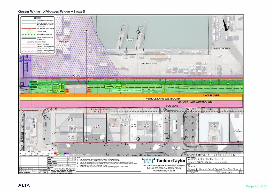
This section of the works has been divided into three stages; Ferry Building to Queens Wharf gates
(40m), Queens Wharf gates to POAL gates (165m) and POAL gates to end of palisade wall (95m),
these are shown below in figures 8, 9 and 10. Where the works cross the entrance to Queens Wharf,
one lane in and one lane out will be kept in operation, opposed to the current 2 lanes in and 2 lanes
out. Where the works cross the POAL entrance, one lane will be kept in operation, allowing one-way
access and egress. It is envisaged that all pedestrians will be diverted to the southern side of Quay
Street throughout all phases of the works, once the entire works are completed the northern
footpath will be re-opened.
Timber hoarding 2.4m high will be placed around all site boundaries and either protection will be
provided to the existing red fence, or the fence will be temporarily removed and replaced following
the works. The construction site is generally 13m wide, allowing traffic to enter the site at the
western end and proceed through the site, exiting at the eastern end. This site layout maintains
three traffic lanes (including bus lane) and a bi-directional cycleway on Quay Street. Where trucks
enter and exit the site, they will be crossing the cycle lane, with traffic control being required each
time a vehicle crosses the cycle way.
Figure 8: Site Layout and Staging – POAL gates to end of palisade wall
Figure 9: Site Layout and Staging – Queens Wharf gates to POAL gates
Figure 10: Site Layout and Staging – Ferry Building to Queens Wharf gates

Page 28 of 43
See Appendix 2 with full staging drawings.
Construction Method
The methodology detailed below covers all phases of the works from initial site mobilisation through
to backfill of capping beam up to underside of paving. For certain parts of the works, the
methodology is subject to plant choice by the contractor and where this occurs we have provided
several options.
7.3.1 Piling
The piling consists of installing approximately 900mm diameter concrete reinforced piles at
approximately 2.5m centres. There are several potential methods available for installing the piles,
which is dependent upon the equipment available to the contractor. The method detailed below is
based on boring the piles into place, using an oversized casing to pile through any potential
obstructions.
The piling method is based on the following approach:
• Shallow pile trench may be excavated, and pile guide rails installed to provide pile location
accuracy depending on the contractors preferred method.
• Oversized starter casing will have teeth and strengthening ring (shoe) welded to the starter
casing and will be drilled through the rock apron until it meets refusal
• If an obstruction is encountered, a coring barrel will be used to drill inside the starter casing,
coring through the obstruction.
• Should core drilling through the obstruction be unsuccessful, a drop tool may be required to
break and then remove the obstruction.
• Drilling will utilise a casing oscillator while removing spoil until below rock apron.
• Once below the rock apron the secondary pile casing (also with teeth) will be drilled inside
the started casing, until it is set in competent material to form a groundwater seal.
• A drill bucket or auger can be used to drill and excavate the remaining length of pile. Spoil
will be emptied into portable skips for loading out into trucks.
• A cleaning bucket will be used to clean the socket in the rock.
• The starter casing can be rotated and extracted.
• The reinforcing cage will be installed in the casing using the 100-tonne support crane.
• Concrete to be tremie poured into pile using a pump and filled to design level. Concrete
trucks will access the site from the western end and leave from the eastern gate.
• If the casing can be removed, then it will be removed during the concrete pour.

Page 29 of 43
AVERAGE PILING CYCLE TIME
Activity Duration
Pile set up 1 Hr
Bore through basalt seawall foundation 4-5 Hr
Bore through Tauranga Group 2-3 Hr
Socket pile into ECBF 1 Hr
Install reinforcing cage and concrete 3 Hr
7.3.2 Piling Duration
The piling duration for this phase of the works is based on two piles per day for a 2-rig crew for three
to four months. The intention of using 2 piling rigs is to boost productivity where a pile is difficult to
install, allowing the second piling rig to proceed installing the rest of the piles while the first rig
continues to install the difficult pile.
7.3.3 Obstructions
Where obstructions are present and pose a difficulty to install an approximately 900mm diameter
steel casing, a second oversized (1200mm diameter) temporary casing could be installed first with
the core barrel cutting through these obstructions and the 900mm permanent casing being installed
inside of this. Once the zone containing the obstructions has been passed, the 900mm casing would
be installed for the remaining length. The oversized casing would then be removed once piling
complete.
7.3.4 Alternative Piling Methods
Other options should be made available to contractors such as using grout to bind the granular
material and boulders within the seawall to provide a solid mass to core through. This may help
where obstructions such as boulders are encountered, which can jam the piling rig.
7.3.5 Piling Plant
To provide context and size information, Appendix 1 includes pictures of plant similar to that likely
be used on this section of the works.
7.3.6 Capping Beam
Installation of the capping beam will commence once all piles have been installed, or once a section
of piles have been installed allowing adequate working space. Due to the size of the capping beam
being approximately 1.3m wide x 0.8m deep an excavation of at least 2.5m wide x 2.0m deep (if
shoring used) would be required to allow for enough working space for blinding, backfill above the
capping beam and temporary works. The excavation could either be battered if enough space was
available, although this would result in the excavation being up to 5m wide, or temporary shoring
such as trench shields could be utilised to provide a narrower trench. Localised piling may also be
required to protect services, at the Queens Wharf and POAL entrances or to provide trench stability
where trench shields are not able to be used. This could consist of sheet piling or some other form of

Page 30 of 43
vibro piling but would only be used intermittently in small sections for short durations . Propping of
the red fence foundations may be required, dependent on the size of these foundations.
Excavation of the trench would most likely be carried out by a 12 – 30 tonne excavator. Due to the
ground conditions, excavator mounted hydraulic breakers would also more than likely be required
for breaking through existing layers of concrete and fill materials which may consists of basalt
boulders and other hard materials. These would be used on a regular basis during excavation of this
trench. If groundwater / seawater is encountered during capping beam works this will be pumped,
treated appropriately and discharged as appropriate. This is discussed in more detail in the Tonkin +
Taylor Contaminated Land Assessment reports and the Tonkin + Taylor Environmental Monitoring
and Management Response Plan reports.
Once the trench has been excavated to the level required for forming the capping beam, the excess
pile casing would be cut off. Breaking could be required of the pile heads by mechanical means such
as hand-held breakers, machine mounted breakers or hydraulic pile breaker. Broken out concrete
from the pile heads would be loaded into trucks and disposed from site.
Blinding would then be poured to the underside of the capping beam, this could either be direct
from the truck or by use of a concrete pump, depending on the location. Reinforcing steel, either
prefabricated or tied in place would be installed. Reusable formwork would be placed to either sides
of the beam, and concrete poured following this. Again, this could either be placed direct from the
truck or by use of a concrete pump.
Once the capping beam has been formed, formwork would be removed and backfill, such as GAP40
would be imported and placed up to the underside of the pavement sub base. Provision should be
made for contractors to use flowable fill in locations that are difficult to access for compaction.

Page 31 of 43
1 APPENDIX
Appendix Description Source
1 Indicative plant images Google
2 Staging drawings and cross sections Alta

Page 32 of 43
Appendix 1 – Indicative plant images
75 Tonne Piling Rig
100 Tonne Crawler Crane

Page 33 of 43
150 Tonne Crawler Crane

Appendix 2 – Staging Drawings PRINCES WHARF - STAGE 1

Page 35 of 43
PRINCES WHARF STAGE 2

Page 36 of 43
PRINCES WHARF CROSS SECTIONS
6.2m
*Pedestrian Footpath
width varies from
3.1m to 6.0m
*Pedestrian Footpath
width varies from
3.1m to 6.0m
6.2m 6.2m

Page 37 of 43
PRINCES WHARF CROSS SECTIONS
*Pedestrian Footpath
width varies from
3.1m to 6.0m
6.2m

Page 38 of 43
FERRY BASIN - LANDSIDE OPTION

Page 39 of 43
FERRY BASIN - SEASIDE OPTION

Page 40 of 43
QUEENS WHARF TO MARSDEN WHARF – STAGE 1

Page 41 of 43
QUEENS WHARF TO MARSDEN WHARF – STAGE 2 – DRAWING 1

Page 42 of 43
QUEENS WHARF TO MARSDEN WHARF – STAGE 2 – DRAWING 2
Page 43 of 43
QUEENS WHARF TO MARSDEN WHARF – STAGE 3
Top Related