


Languages
Pages
Legal

5: Link Layer and Local Area Networks 5d-1
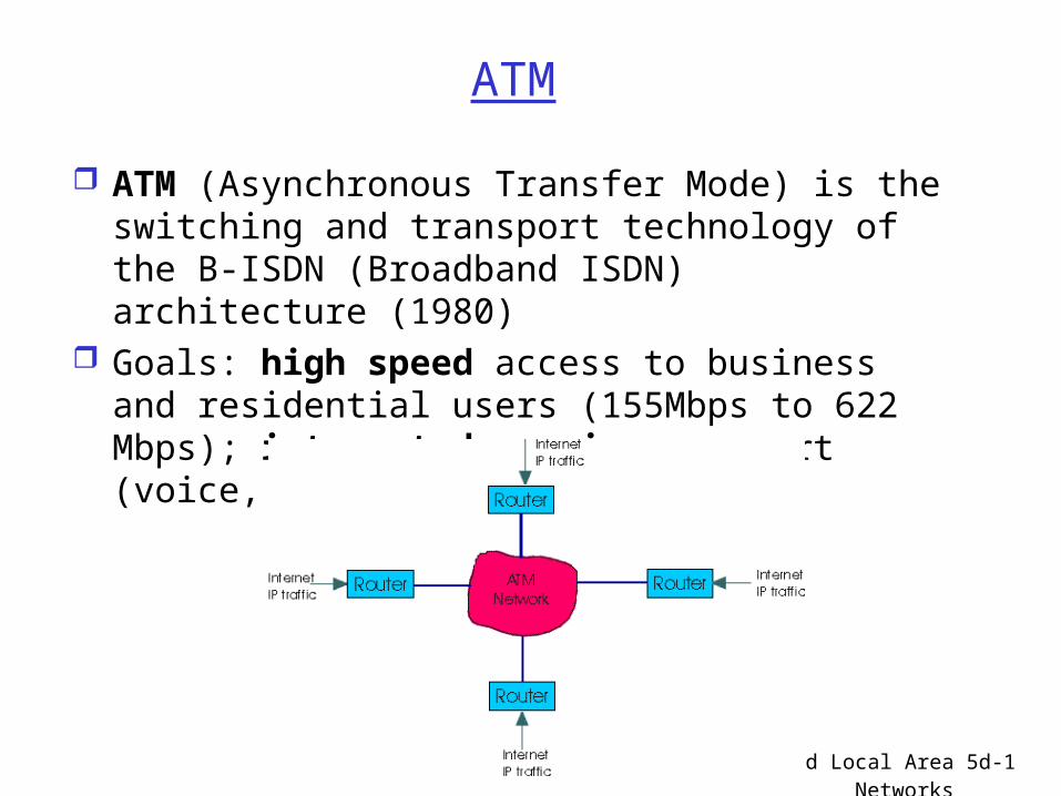
ATM
ATM (Asynchronous Transfer Mode) is the switching and transport technology of the B-ISDN (Broadband ISDN) architecture (1980)
Goals: high speed access to business and residential users (155Mbps to 622 Mbps); integrated services support (voice, data, video, image)
5: Link Layer and Local Area Networks 5d-2
Traditional (wired) ATM networks
ATM or cell-relay, is an evolved technology from the traditional packet-switched and frame relay technologies as a result of improvement in digital communications.
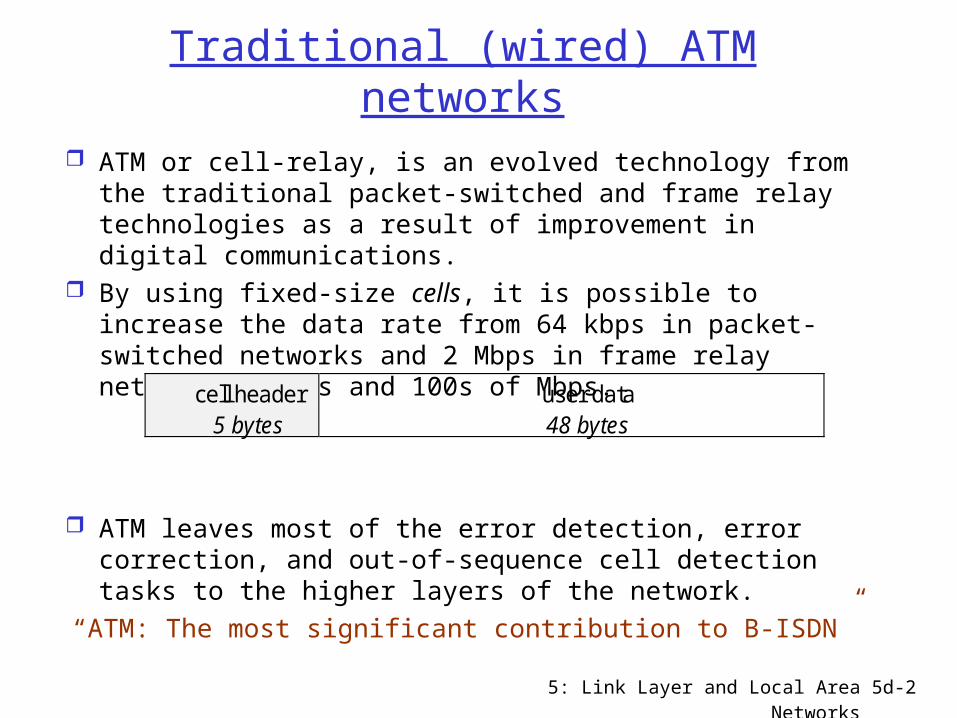
By using fixed-size cells, it is possible to increase the data rate from 64 kbps in packet-switched networks and 2 Mbps in frame relay networks to 10s and 100s of Mbps.
ATM leaves most of the error detection, error correction, and out-of-sequence cell detection tasks to the higher layers of the network. “ATM: The most significant contribution to B-ISDN”
cell header5 bytes
user data48 bytes
5: Link Layer and Local Area Networks 5d-3
Logical connections in ATM
VCC (virtual channel connection) is the basic unit of switching in B-ISDN and is set up between end user pairs.
A variable-rate, full-duplex flow of ATM cells is exchanged over the VC connections.
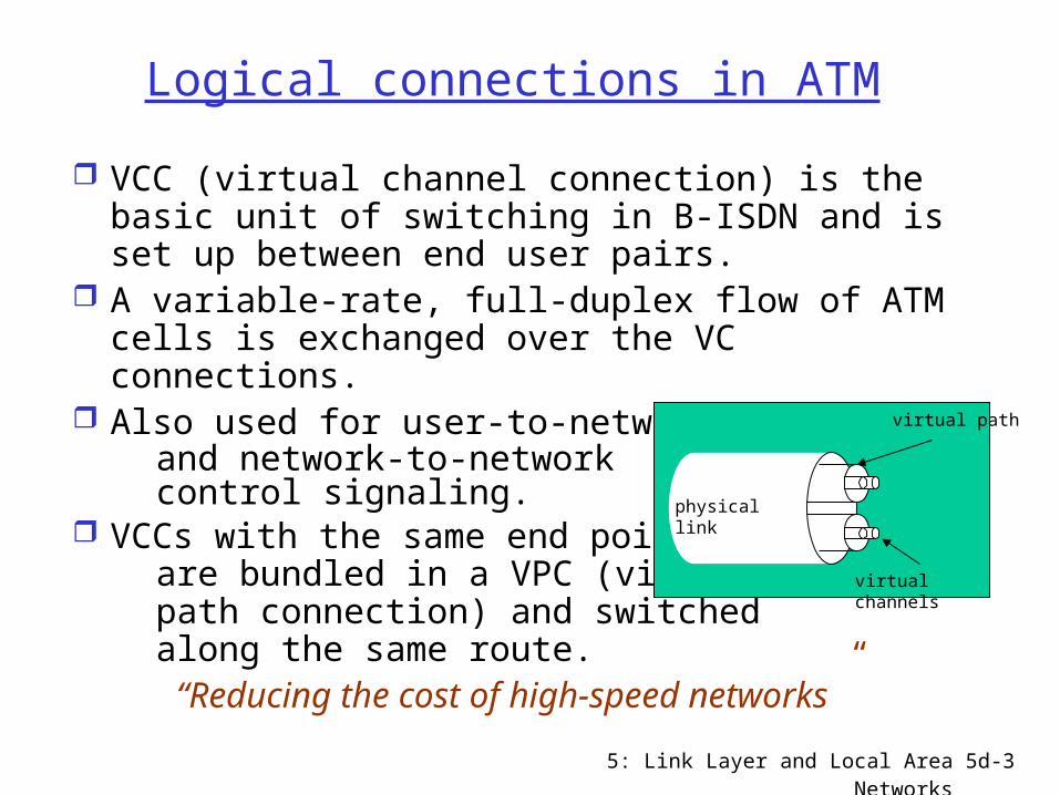
Also used for user-to-network and network-to-network control signaling. VCCs with the same end point are bundled in a VPC (virtual path connection) and switched along the same route.
“Reducing the cost of high-speed networks”
physical link
virtual path
virtual channels

5: Link Layer and Local Area Networks 5d-4
ATM cell header format
An n-bit label in VPI and VCI can support up to 2n paths and channels, respectively.
HEC is mainly used for error detection and can be used for as a mechanism to control out-of-sequence cell arrival errors.
PTI distinguishes particular classes of information flow.
CLP (cell-loss priority) is used for congestion control.generic flow control virtual path identifier
virtual path identifier virtual channel identifier
virtual channel identifier
virtual channel identifier payload type id CLP
header error control
12345
8 7 6 5 4 3 2 1 bits
1
2
3
4
5
bytes
Cell header format for user-network interface
5: Link Layer and Local Area Networks 5d-5
Support of different types of traffic
Real-time services: concern about the amount of delay and the variability of delay (jitter) involve a flow of information to a user intended to
reproduce that flow at a source (e.g., voice and video transmissions)
include CBR, rt-VBR Non-real-time services: for applications that have
bursty traffic characteristics with no tight constraint on delay/jitter. more flexibility for the network to handle traffic and to
use statistical multiplexing (e.g., TCP flows) include nrt-VBR, UBR, and ABR UBR suitable for applications that can tolerate variable
delays and some cell losses (such as TCP-based traffic)• no initial commitment and no congestion feedback
– best suited for best-effort QoS IP applications
5: Link Layer and Local Area Networks 5d-6
Support of different types of traffic (cont.)
ABR: defined to improve service to bursty traffic sources by specifying
• peak cell rate (PCR)• minimum cell rate (MCR)
Network allocates at least MCR to an ABR source. The leftover capacity is shared fairly among all ABR
and UBR sources. Recently a guaranteed cell rate (GCR) has proposed
by the ATM Forum to provide a minimum rate guarantee to VCs at the frame level to enhance the UBR service.

5: Link Layer and Local Area Networks 5d-7
ATM VCs
Focus on bandwidth allocation facilities (in contrast to IP best effort)
ATM main role today: “switched” link layer for IP-over-ATM
ATM is a virtual circuit transport: cells (53 bytes) are carried on VCs
in IP over ATM: Permanent VCs (PVCs) between IP routers;
scalability problem: N(N-1) VCs between all IP router pairs

5: Link Layer and Local Area Networks 5d-8
ATM VCs
Switched VCs (SVCs) used for short lived connections
Pros of ATM VC approach: Can guarantee QoS performance to a connection
mapped to a VC (bandwidth, delay, delay jitter)
Cons of ATM VC approach: Inefficient support of datagram traffic; PVC solution
(one PVC between each host pair) does not scale; SVC introduces excessive latency on short lived
connections High SVC processing Overhead

5: Link Layer and Local Area Networks 5d-9
ATM Address Mapping
Router interface (to ATM link) has two addresses: IP and ATM address.
To route an IP packet through the ATM network, the IP node:
(a) inspects own routing tables to find next IP router address(b) then, using ATM ARP table, finds ATM addr of next router(c) passes packet (with ATM address) to ATM layer
At this point, the ATM layer takes over:(1) it determines the interface and VC on which to send out
the packet(2) if no VC exists (to that ATM addr) a SVC is set up

5: Link Layer and Local Area Networks 5d-10
ATM Physical Layer
Two Physical sublayers:
(a) Physical Medium Dependent (PMD) sublayer (a.1) SONET/SDH: transmission frame structure
(like a container carrying bits); • bit synchronization; • bandwidth partitions (TDM); • several speeds: OC1 = 51.84 Mbps; OC3 = 155.52
Mbps; OC12 = 622.08 Mbps (a.2) TI/T3: transmission frame structure (old
telephone hierarchy): 1.5 Mbps/ 45 Mbps (a.3) unstructured: just cells (busy/idle)

5: Link Layer and Local Area Networks 5d-11
ATM Physical Layer (more)
Second physical sublayer
(b) Transmission Convergence Sublayer (TCS): it adapts PMD sublayer to ATM transport layer
TCS Functions: Header checksum generation: 8 bits CRC; it protects
a 4-byte header; can correct all single errors. Cell delineation With “unstructured” PMD sublayer, transmission of
idle cells when no data cells are available in the transmit queue

5: Link Layer and Local Area Networks 5d-12
ATM Layer
ATM layer in charge of transporting cells across the ATM network
ATM layer protocol defines ATM cell header format (5bytes);
payload = 48 bytes; total cell length = 53 bytes
5: Link Layer and Local Area Networks 5d-13
ATM Layer
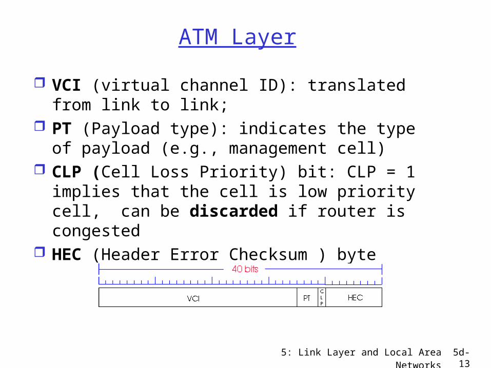
VCI (virtual channel ID): translated from link to link;
PT (Payload type): indicates the type of payload (e.g., management cell)
CLP (Cell Loss Priority) bit: CLP = 1 implies that the cell is low priority cell, can be discarded if router is congested
HEC (Header Error Checksum ) byte
5: Link Layer and Local Area Networks 5d-14
ATM Adaptation Layer (AAL)
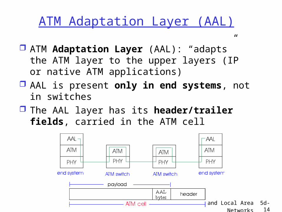
ATM Adaptation Layer (AAL): “adapts” the ATM layer to the upper layers (IP or native ATM applications)
AAL is present only in end systems, not in switches
The AAL layer has its header/trailer fields, carried in the ATM cell

5: Link Layer and Local Area Networks 5d-15
ATM Adaptation Layer (AAL) [more]
Different versions of AAL layers, depending on the service to be supported by the ATM transport: AAL1: for CBR (Constant Bit Rate) services such as
circuit emulation AAL2: for VBR (Variable Bit Rate) services such as
MPEG video AAL5: for data (e.g., IP datagrams)

5: Link Layer and Local Area Networks 5d-16
ATM Adaptation Layer (AAL) [more]
Two sublayers in AAL: (Common Part) Convergence Sublayer:
encapsulates IP payload
Segmentation/Reassembly Sublayer: segments/reassembles the CPCS (often quite large, up to 65K bytes) into 48 byte ATM segments
5: Link Layer and Local Area Networks 5d-17
AAL5 - Simple And Efficient AL (SEAL)
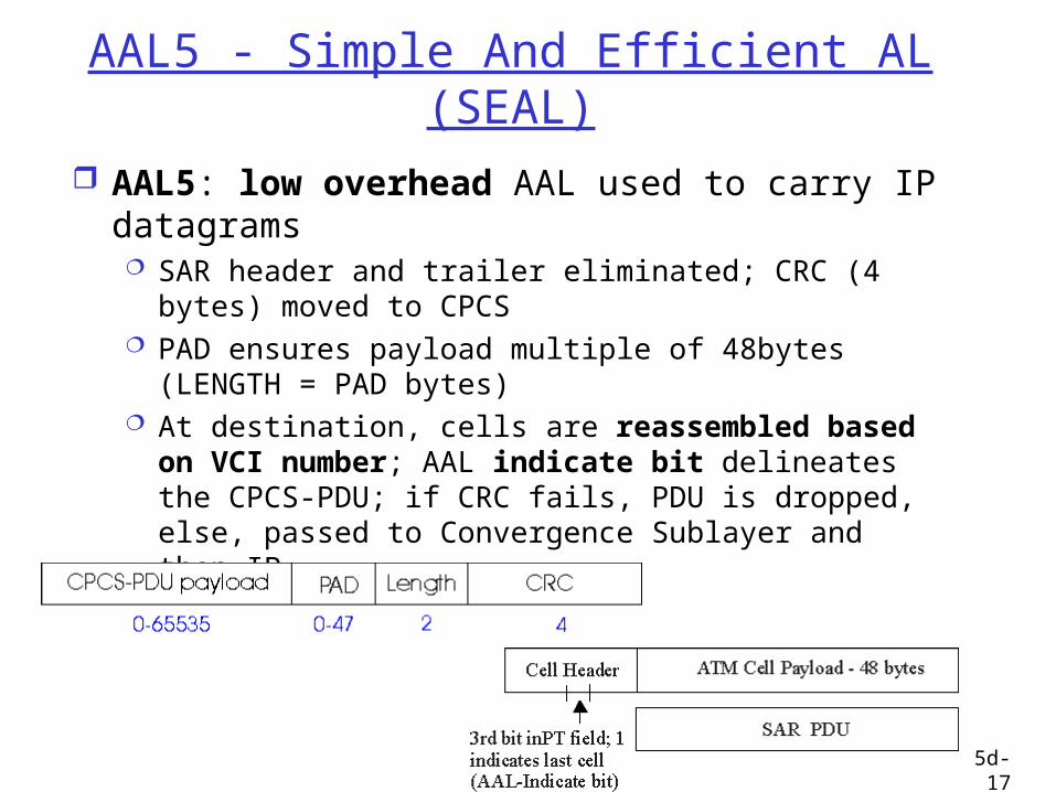
AAL5: low overhead AAL used to carry IP datagrams SAR header and trailer eliminated; CRC (4 bytes)
moved to CPCS PAD ensures payload multiple of 48bytes (LENGTH =
PAD bytes) At destination, cells are reassembled based on
VCI number; AAL indicate bit delineates the CPCS-PDU; if CRC fails, PDU is dropped, else, passed to Convergence Sublayer and then IP
5: Link Layer and Local Area Networks 5d-18
Datagram Journey in IP-over-ATM Network
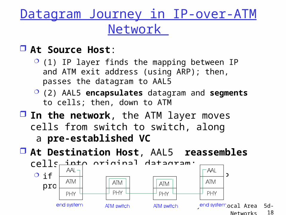
At Source Host: (1) IP layer finds the mapping between IP and ATM
exit address (using ARP); then, passes the datagram to AAL5
(2) AAL5 encapsulates datagram and segments to cells; then, down to ATM
In the network, the ATM layer moves cells from switch to switch, along a pre-established VC
At Destination Host, AAL5 reassembles cells into original datagram; if CRC OK, datagram is passed up the IP protocol.
5: Link Layer and Local Area Networks 5d-19
ARP in ATM Nets
ATM can route cells only if it has the ATM address Thus, IP must translate exit IP address to ATM address
The IP/ATM address translation is done by ARP (Address Recognition Protocol)
Generally, ATM ARP table does not store all ATM addresses: it must discover some of them
Two techniques: broadcast ARP servers
5: Link Layer and Local Area Networks 5d-20
ARP in ATM Networks (more)
(1) Broadcast the ARP request to all destinations:
(1.a) the ARP Request message is broadcast to all ATM destinations using a special broadcast VC;
(1.b) the ATM destination which can match the IP address returns (via unicast VC) the IP/ATM address map;
Broadcast overhead prohibitive for large ATM nets.
5: Link Layer and Local Area Networks 5d-21
ARP in ATM Nets (more)
(2) ARP Server:
(2.a) source IP router forwards ARP request to server on dedicated VC (Note: all such VCs from routers to ARP have same ID)
(2.b) ARP server responds to source router with IP/ATM translation
Hosts must register themselves with the ARP server
Comments: more scaleable than ABR Broadcast approach (no broadcast storm). However, it requires an ARP server, which may be swamped with requests

5: Link Layer and Local Area Networks 5d-22
X.25 and Frame Relay
Wide Area Network technologies (like ATM); also, both Virtual Circuit oriented , like ATM
X.25 was born in mid ‘70s, with the support of the Telecom Carriers, in response to the ARPANET datagram technology (religious war..)
Frame relay emerged from ISDN technology (in late ‘80s)
Both X.25 and Frame Relay can be used to carry IP datagrams; thus, they are viewed as Link Layers by the IP protocol layer (and are thus covered in this chapter)

5: Link Layer and Local Area Networks 5d-23
X.25
X.25 builds a VC between source and destination for each user connection
Along the path, error control (with retransmissions) on each hop using LAP-B, a variant of the HDLC protocol
Also, on each VC, hop by hop flow control using credits; congestion arising at an intermediate node
propagates to source via backpressure
5: Link Layer and Local Area Networks 5d-24
X.25
As a result, packets are delivered reliably and in sequence to destination; per flow credit control guarantees fair sharing
Putting “intelligence into the network” made sense in mid 70s (dumb terminals without TCP)
Today, TCP and practically error free fibers favor pushing the “intelligence to the edges”; moreover, gigabit routers cannot afford the X.25 processing overhead
As a result, X.25 is rapidly becoming extinct

5: Link Layer and Local Area Networks 5d-25
Frame Relay
Designed in late ‘80s and widely deployed in the ‘90s
FR VCs have no error control Flow (rate) control is end to end; much
less processing O/H than hop by hop credit based flow control
5: Link Layer and Local Area Networks 5d-26
Frame Relay (more)
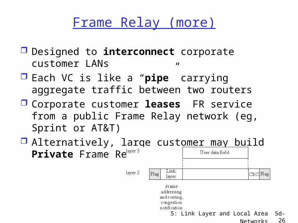
Designed to interconnect corporate customer LANs
Each VC is like a “pipe” carrying aggregate traffic between two routers
Corporate customer leases FR service from a public Frame Relay network (eg, Sprint or AT&T)
Alternatively, large customer may build Private Frame Relay network.

5: Link Layer and Local Area Networks 5d-27
Frame Relay (more)
Frame Relay implements mostly permanent VCs (aggregate flows)
10 bit VC ID field in the Frame header
If IP runs on top of FR, the VC ID corresponding to destination IP address is looked up in the local VC table
FR switch simply discards frames with bad CRC (TCP retransmits..)

5: Link Layer and Local Area Networks 5d-28
Frame Relay -VC Rate Control
CIR = Committed Information Rate, defined for each VC and negotiated at VC set up time; customer pays based on CIR
DE bit = Discard Eligibility bit in Frame header DE bit = 0: high priority, rate compliant frame; the
network will try to deliver it at “all costs” DE bit = 1: low priority, “marked” frame; the
network discards it when a link becomes congested (ie, threshold exceeded)

5: Link Layer and Local Area Networks 5d-29
Frame Relay - CIR & Frame Marking
Access Rate: rate R of the access link between source router (customer) and edge FR switch (provider); 64Kbps < R < 1,544Kbps
Typically, many VCs (one per destination router) multiplexed on the same access trunk; each VC has own CIR
Edge FR switch measures traffic rate for each VC; it marks
(ie DE <= 1) frames which exceed CIR (these may be later dropped)

5: Link Layer and Local Area Networks 5d-30
Frame Relay - Rate Control
Frame Relay provider “almost” guarantees CIR rate (except for overbooking)
No delay guarantees, even for high priority traffic
Delay will in part depend on rate measurement interval Tc; the larger Tc, the burstier the traffic injected in the network, the higher the delays
Frame Relay provider must do careful traffic engineering before committing to CIR, so that it can back up such commitment and prevent overbooking
Frame Relay CIR is the first example of traffic rate dependent charging model for a packet switched network
Top Related