


Languages
Pages
Legal

Assembly Instructions Amphenol®
273Amphenol Corporation Tel: 800-627-7100 www.amphenolrf.com
Assem
bly
274Amphenol Corporation Tel: 800-627-7100 www.amphenolrf.com
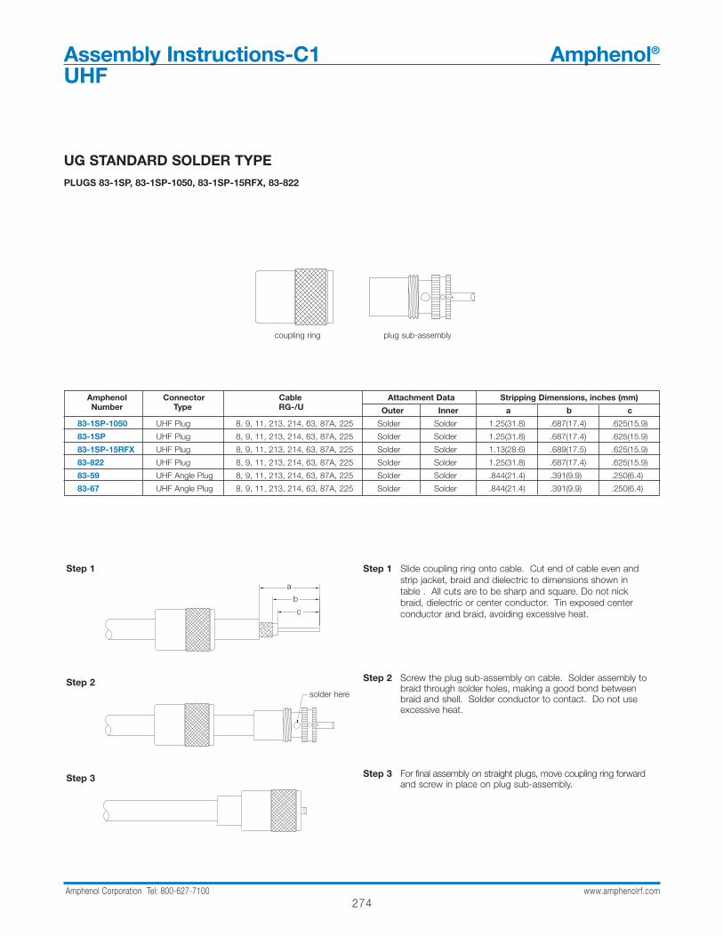
UG STANDARD SOLDER TYPEPLUGS 83-1SP, 83-1SP-1050, 83-1SP-15RFX, 83-822
Step 1
Step 2
Step 3
Step 1 Slide coupling ring onto cable. Cut end of cable even and strip jacket, braid and dielectric to dimensions shown in table . All cuts are to be sharp and square. Do not nick braid, dielectric or center conductor. Tin exposed center conductor and braid, avoiding excessive heat.
Step 2 Screw the plug sub-assembly on cable. Solder assembly to braid through solder holes, making a good bond between braid and shell. Solder conductor to contact. Do not use excessive heat.
Step 3 For final assembly on straight plugs, move coupling ring forward and screw in place on plug sub-assembly.
coupling ring plug sub-assembly
Amphenol Connector Cable Attachment Data Stripping Dimensions, inches (mm)Number Type RG-/U Outer Inner a b c
83-1SP-1050 UHF Plug 8, 9, 11, 213, 214, 63, 87A, 225 Solder Solder 1.25(31.8) .687(17.4) .625(15.9)
83-1SP UHF Plug 8, 9, 11, 213, 214, 63, 87A, 225 Solder Solder 1.25(31.8) .687(17.4) .625(15.9)
83-1SP-15RFX UHF Plug 8, 9, 11, 213, 214, 63, 87A, 225 Solder Solder 1.13(28.6) .689(17.5) .625(15.9)
83-822 UHF Plug 8, 9, 11, 213, 214, 63, 87A, 225 Solder Solder 1.25(31.8) .687(17.4) .625(15.9)
83-59 UHF Angle Plug 8, 9, 11, 213, 214, 63, 87A, 225 Solder Solder .844(21.4) .391(9.9) .250(6.4)
83-67 UHF Angle Plug 8, 9, 11, 213, 214, 63, 87A, 225 Solder Solder .844(21.4) .391(9.9) .250(6.4)
A
B
CSTEP 1
SOLDER HERE
STEP 2
STEP 3
a
b
c
solder here
Assembly Instructions-C1 Amphenol®
UHF

275Amphenol Corporation Tel: 800-627-7100 www.amphenolrf.com
Assem
bly
UG STANDARD SOLDER TYPE WITH REDUCING ADAPTER
FOR PLUGS 83-1SP, 83-1SP-1050, 83-1SP-15RFX, 83-822, USING 83-168 83-168-RFX, OR 83-185, 83-185-RFX REDUCING ADAPTER
Step 1
Step 2
Step 3
Step 4
C
STEP 2 c
Step 1 Slide coupling ring and adapter onto cable. Cut end of cable even and strip jacket to dimension shown in table.
Step 2 Position adapter flush with end of cable jacket. Fan braid slightly and fold back over body of adapter as shown. Press braid down over body and trim to dimension b. Bare conductor to dimension c shown in table. Tin exposed center conductor and braid, avoiding excessive heat.
Step 3 Screw plug sub-assembly onto adapter. Solder braid to shellthrough solder holes, making a good bond between braid and shell. Solder conductor to contact. Do not use excessive heat.
Step 4 For final assembly, screw coupling ring onto plug sub-assembly.
coupling ring 83-168 or 83-168-RFX for RG-59 plug sub-assembly83-185 or 83-185-RFX for RG-58
reducing adapter
Amphenol Connector Cable RG-/U Cable RG-/U Attachment Data Using 83-168 or 83-185 Using 83-168-RFX or 83-185-RFX
Number Type (using 83-168 (using 83-185 Outer Inner
Stripping Dims, inches (mm) Stripping Dims, inches (mm)or 83-138-RFX) or 83-185-RFX) a b c a b c
83-1SP UHF Plug 59 58 Solder Solder .750(19.1) .375(9.5) .625(15.9) .689(17.5) .375(9.5) .551(14.0)
83-1SP-1050 UHF Plug 59 58 Solder Solder .750(19.1) .375(9.5) .625(15.9) .689(17.5) .375(9.5) .551(14.0)
83-1SP-15RFX UHF Plug 59 58 Solder Solder .750(19.1) .375(9.5) .625(15.9) .689(17.5) .375(9.5) .551(14.0)
83-750 UHF Plug 59 58 Solder Solder .750(19.1) .375(9.5) .625(15.9) .689(17.5) .375(9.5) .551(14.0)
83-822 UHF Plug 59 58 Solder Solder .750(19.1) .375(9.5) .625(15.9) .689(17.5) .375(9.5) .551(14.0)
A
BSTEP 1
STEP 3
SOLDER HERE
STEP 4
a
solder here
b
Assembly Instructions-C2 Amphenol®
UHF
276Amphenol Corporation Tel: 800-627-7100 www.amphenolrf.com
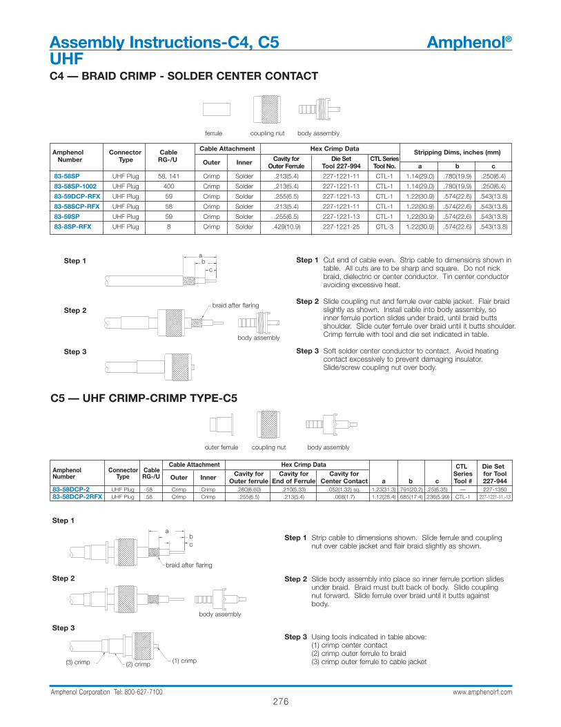
C4 — BRAID CRIMP - SOLDER CENTER CONTACT
Step 1
Step 2
Step 3
Step 1 Cut end of cable even. Strip cable to dimensions shown in table. All cuts are to be sharp and square. Do not nick braid, dielectric or center conductor. Tin center conductor avoiding excessive heat.
Step 2 Slide coupling nut and ferrule over cable jacket. Flair braid slightly as shown. Install cable into body assembly, so inner ferrule portion slides under braid, until braid butts shoulder. Slide outer ferrule over braid until it butts shoulder. Crimp ferrule with tool and die set indicated in table.
Step 3 Soft solder center conductor to contact. Avoid heating contact excessively to prevent damaging insulator. Slide/screw coupling nut over body.
ferrule coupling nut body assembly
Amphenol Connector Cable Cable Attachment Hex Crimp Data Stripping Dims, inches (mm)Number Type RG-/U Outer Inner Cavity for Die Set CTL Series
Outer Ferrule Tool 227-994 Tool No. a b c
83-58SP UHF Plug 58, 141 Crimp Solder .213(5.4) 227-1221-11 CTL-1 1.14(29.0) .780(19.9) .250(6.4)
83-58SP-1002 UHF Plug 400 Crimp Solder .213(5.4) 227-1221-11 CTL-1 1.14(29.0) .780(19.9) .250(6.4)
83-59DCP-RFX UHF Plug 59 Crimp Solder .255(6.5) 227-1221-13 CTL-1 1.22(30.9) .574(22.6) .543(13.8)
83-58SCP-RFX UHF Plug 58 Crimp Solder .213(5.4) 227-1221-11 CTL-1 1.22(30.9) .574(22.6) .543(13.8)
83-59SP UHF Plug 59 Crimp Solder .255(6.5) 227-1221-13 CTL-1 1.22(30.9) .574(22.6) .543(13.8)
83-8SP-RFX UHF Plug 8 Crimp Solder .429(10.9) 227-1221-25 CTL-3 1.22(30.9) .574(22.6) .543(13.8)
C5 — UHF CRIMP-CRIMP TYPE-C5
outer ferrule coupling nut body assembly
Step 1
Step 2
Step 3
Step 1 Strip cable to dimensions shown. Slide ferrule and couplingnut over cable jacket and flair braid slightly as shown.
Step 2 Slide body assembly into place so inner ferrule portion slidesunder braid. Braid must butt back of body. Slide coupling nut forward. Slide ferrule over braid until it butts against body.
Step 3 Using tools indicated in table above: (1) crimp center contact (2) crimp outer ferrule to braid(3) crimp outer ferrule to cable jacket
Amphenol Connector CableCable Attachment Hex Crimp Data CTL Die Set
Number Type RG-/U Outer Inner Cavity for Cavity for Cavity for Series for Tool Outer ferrule End of Ferrule Center Contact a b c Tool # 227-944
83-58DCP-2 UHF Plug 58 Crimp Crimp .260(6.60) .210(5.33) .052(1.32) sq. 1.23(31.3) .791(20.2) .25(6.35) — 227-135083-58DCP-2RFX UHF Plug 58 Crimp Crimp .255(6.5) .213(5.4) .068(1.7) 1.12(28.4) .685(17.4) .236(5.99) CTL-1 227-1221-11,-13
A
B
CSTEP 1
BODY ASSEMBLY
STEP 2
BRAID AFTER FLARING
STEP 3
.250 (6.4)
1.23 (31.3)
.791 (20.2)
BRAID AFTER FLARING
STEP 1
(3) CRIMP (2) CRIMP(1) CRIMP
STEP 3
ab
c
braid after flaring
body assembly
abc
braid after flaring
body assembly
(3) crimp (1) crimp(2) crimp
Assembly Instructions-C4, C5 Amphenol®
UHF
277Amphenol Corporation Tel: 800-627-7100 www.amphenolrf.com
Assem
bly
Assembly Instructions-C6 Amphenol®
UHF
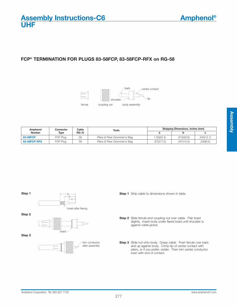
FCP® TERMINATION FOR PLUGS 83-58FCP, 83-58FCP-RFX on RG-58
Step 1
Step 2
Step 3
Step 1 Strip cable to dimensions shown in table.
Step 2 Slide ferrule and coupling nut over cable. Flair braid slightly. Insert body under flared braid until shoulder is against cable jacket.
Step 3 Slide nut onto body. Grasp cable. Push ferrule over barb and up against body. Crimp tip of center contact with pliers, or if you prefer, solder. Then trim center conductor even with end of contact.
Amphenol Connector Cable Tools Stripping Dimensions, inches (mm)Number Type RG-/U a b c
83-58FCP FCP Plug 58 Pliers & Fiber Grommet in Bag 1.00(25.4) .812(20.6) .500(12.7)
83-58FCP-RFX FCP Plug 58 Pliers & Fiber Grommet in Bag .673(17.0) .547(14.0) .236(6.0)
ferrule coupling nut body assembly
TIPSHOULDER
BARBCENTER CONTACT
A
B
C
BRAID AFTER FLARING
STEP 1
BRAID
STEP 2
TRIM CONDUCTOR AFTER ASSEMBLYSTEP 3
ab
c
braid after flaring
braid
trim conductorafter assembly
shoulder
center contact
tip
barb

278Amphenol Corporation Tel: 800-627-7100 www.amphenolrf.com
Assembly Instructions-C7 Amphenol®
UHF
HOODS FOR ADAPTING PANEL RECEPTACLES TO COAXIAL CABLES
Step 1
Step 2
Step 3
Step 1 Strip cable to dimensions shown. Do not nick center conductor. Tin exposed braid and center conductor.
Step 2 Slide hood over braid. When using double-braided cable, hood goes over inner braid only. Then, in step 3, solder outer braid to outside of hood. Solder Center Conductor into solder cup terminal.
Step 3 Slide hood flush against receptacle and tack-solder hood flange to receptacle flange. Solder hood to braid as shown. Use tape or tubing over section shown.
83-1H (UG-106/U) for RG-8, 10, 11, 12, 63, 79, 115, 149, 213, 21583-765 (UG-177/U) for RG-58, 141
Amphenol Connector Cable Cable Attachment Stripping DimensionsNumber Type RG-/U Outer Inner a b c
83-1H Hood 8, 10, 11, 12, 63, 79, 115, 149, 213, 205 Solder Solder .625(15.8) .500(12.7) .312(7.92)83-765 Hood 58, 141 Solder Solder .750(19.0) .687(17.4) .312(7.92)
83-1H83-765
STEP 1
CUP TERMINALCONDUCTOR INTO SOLDERSOLDER CABLE CENTER
STEP 2
TAPE OR TUBINGOVER THIS SECTION
THREE SOLDER HOLES
ALL AROUND BACK OF HOODSOLDER HERE FOR 83-765
TACK SOLDER FLANGES TOGETHER
SOLDER HERE FOR 83-1H
STEP 3
solder cable center conductorinto solder cup terminal
tape or tubingover this section
tack solder flanges together
solder here for 83-765
solder here for 83-1Hthree solder holes
83-765 83-1H
ab
c
279Amphenol Corporation Tel: 800-627-7100 www.amphenolrf.com
Assem
bly
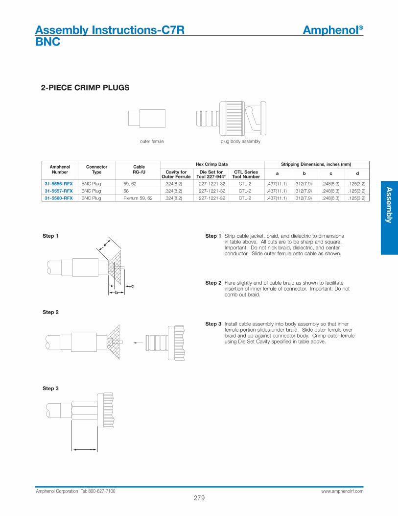
Assembly Instructions-C7R Amphenol®
BNC
2-PIECE CRIMP PLUGS
Step 1 Strip cable jacket, braid, and dielectric to dimensionsin table above. All cuts are to be sharp and square. Important: Do not nick braid, dielectric, and center conductor. Slide outer ferrule onto cable as shown.
Step 2 Flare slightly end of cable braid as shown to facilitate insertion of inner ferrule of connector. Important: Do notcomb out braid.
Step 3 Install cable assembly into body assembly so that inner ferrule portion slides under braid. Slide outer ferrule over braid and up against connector body. Crimp outer ferrule using Die Set Cavity specified in table above.
Amphenol Connector Cable Hex Crimp Data Stripping Dimensions, inches (mm)
Number Type RG-/U Cavity for Die Set for CTL SeriesOuter Ferrule Tool 227-944* Tool Number
a b c d
31-5556-RFX BNC Plug 59, 62 .324(8.2) 227-1221-32 CTL-2 .437(11.1) .312(7.9) .248(6.3) .125(3.2)
31-5557-RFX BNC Plug 58 .324(8.2) 227-1221-32 CTL-2 .437(11.1) .312(7.9) .248(6.3) .125(3.2)
31-5560-RFX BNC Plug Plenum 59, 62 .324(8.2) 227-1221-32 CTL-2 .437(11.1) .312(7.9) .248(6.3) .125(3.2)
outer ferrule plug body assembly
Step 1
Step 2
Step 3
a
bc
280Amphenol Corporation Tel: 800-627-7100 www.amphenolrf.com
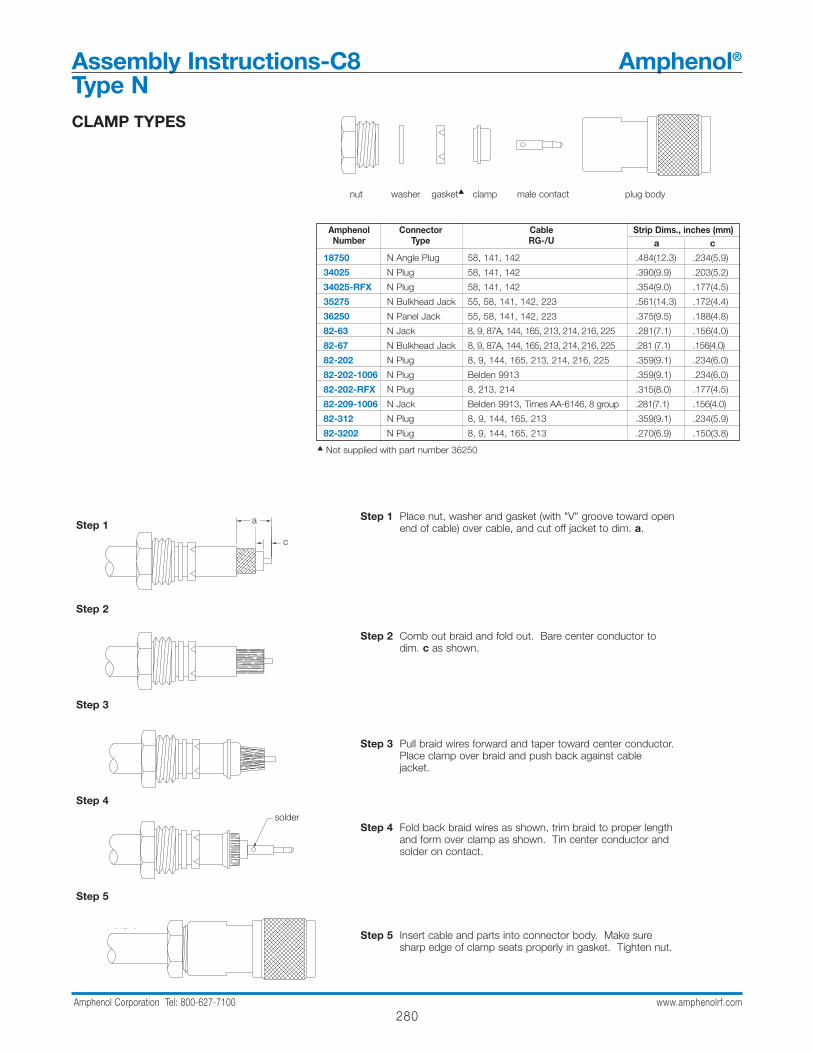
CLAMP TYPES
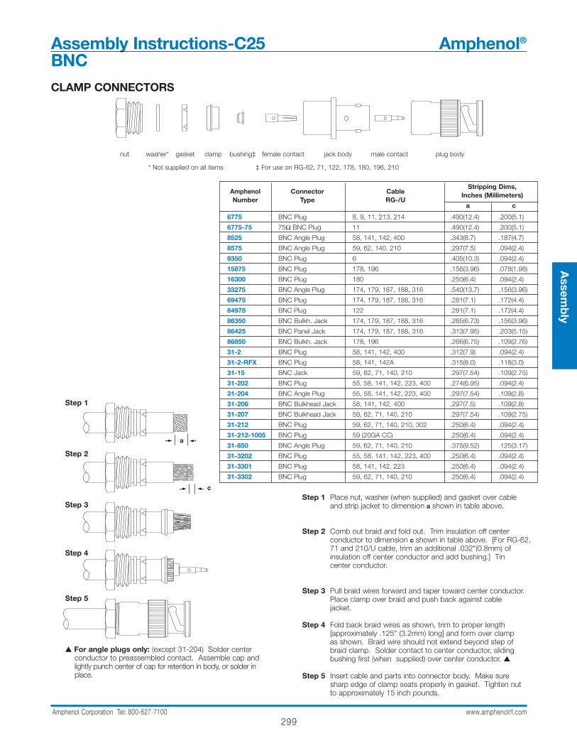
nut washer gasket clamp male contact plug body
Amphenol Connector Cable Strip Dims., inches (mm)Number Type RG-/U a c
18750 N Angle Plug 58, 141, 142 .484(12.3) .234(5.9)
34025 N Plug 58, 141, 142 .390(9.9) .203(5.2)
34025-RFX N Plug 58, 141, 142 .354(9.0) .177(4.5)
35275 N Bulkhead Jack 55, 58, 141, 142, 223 .561(14.3) .172(4.4)
36250 N Panel Jack 55, 58, 141, 142, 223 .375(9.5) .188(4.8)
82-63 N Jack 8, 9, 87A, 144, 165, 213, 214, 216, 225 .281(7.1) .156(4.0)
82-67 N Bulkhead Jack 8, 9, 87A, 144, 165, 213, 214, 216, 225 .281 (7.1) .156(4.0)
82-202 N Plug 8, 9, 144, 165, 213, 214, 216, 225 .359(9.1) .234(6.0)
82-202-1006 N Plug Belden 9913 .359(9.1) .234(6.0)
82-202-RFX N Plug 8, 213, 214 .315(8.0) .177(4.5)
82-209-1006 N Jack Belden 9913, Times AA-6146, 8 group .281(7.1) .156(4.0)
82-312 N Plug 8, 9, 144, 165, 213 .359(9.1) .234(5.9)
82-3202 N Plug 8, 9, 144, 165, 213 .270(6.9) .150(3.8)
Step 1 Place nut, washer and gasket (with "V" groove toward open end of cable) over cable, and cut off jacket to dim. a.
Step 2 Comb out braid and fold out. Bare center conductor todim. c as shown.
Step 3 Pull braid wires forward and taper toward center conductor.Place clamp over braid and push back against cable jacket.
Step 4 Fold back braid wires as shown, trim braid to proper lengthand form over clamp as shown. Tin center conductor and solder on contact.
Step 5 Insert cable and parts into connector body. Make sure sharp edge of clamp seats properly in gasket. Tighten nut.
Step 1
Step 2
Step 3
Step 4
Step 5
A
B
C 1
2
P 3
SOLDER
P 4
STEP 5
a
c
solder
Assembly Instructions-C8 Amphenol®
Type N
Not supplied with part number 36250
281Amphenol Corporation Tel: 800-627-7100 www.amphenolrf.com
Assem
bly
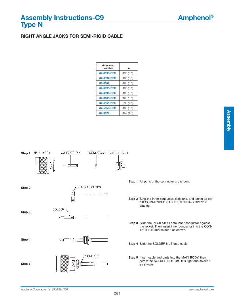
Assembly Instructions-C9 Amphenol®
Type N
Step 1 All parts of the connector are shown.
Step 2 Strip the inner conductor, dielectric, and jacket as per“RECOMMENDED CABLE STRIPPING DIM’S” incatalog.
Step 3 Slide the INSULATOR onto inner conductor againstthe jacket. Then insert inner conductor into the CON-TACT PIN and solder it as shown.
Step 4 Slide the SOLDER NUT onto cable.
Step 5 Insert cable and parts into the MAIN BODY, thenscrew the SOLDER NUT until it is tight and solder itas shown.
Step 1
Step 2
Step 3
Step 4
Step 5
RIGHT ANGLE JACKS FOR SEMI-RIGID CABLE
A
AmphenolNumber A
82-6096-RFX .138 (3.5)
82-6097-RFX .138 (3.5)
82-6162 .138 (3.5)
82-6098-RFX .138 (3.5)
82-6099-RFX .138 (3.5)
82-6163-RFX .138 (3.5)
82-5955-RFX .098 (2.5)
82-5956-RFX .138 (3.5)
82-6124 .157 (4.0)
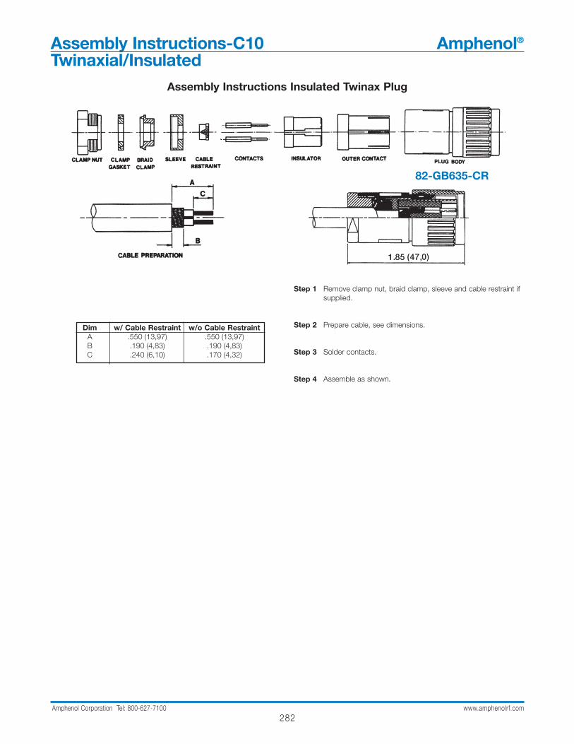
Assembly Instructions-C10 Amphenol®
Twinaxial/Insulated
282Amphenol Corporation Tel: 800-627-7100 www.amphenolrf.com
Step 1 Remove clamp nut, braid clamp, sleeve and cable restraint ifsupplied.
Step 2 Prepare cable, see dimensions.
Step 3 Solder contacts.
Step 4 Assemble as shown.
Assembly Instructions Insulated Twinax Plug
Dim w/ Cable Restraint w/o Cable RestraintA .550 (13,97) .550 (13,97)B .190 (4,83) .190 (4,83)C .240 (6,10) .170 (4,32)
82-GB635-CR

283Amphenol Corporation Tel: 800-627-7100 www.amphenolrf.com
Assem
bly
CRIMP-CRIMP TYPES
Step 1
Step 2
Step 3
crimp here
Step 1 Strip cable jacket, braid, and dielectric to dimensions shown. All cuts are to be sharp and square. Important: Do not nick braid, dielectric, and center conductor. Tinning of center conductor is not necessary if contact is to be crimped. For solder method, tin center conductor avoiding excessive heat.
Step 2 Slide outer ferrule onto cable as shown. Flare slightly end of cable braid as shown to facilitate insertion of inner ferrule. Important: Do not comb out braid.Place contact on cable center conductor so it butts against cable dielectric. Center conductor should be visible through inspection hole in contact. Crimp or solder contact in place as follows:Crimp Method: Use Die Set Cavity for contact indicated in table above.Solder Method: Soft solder contact to cable center conductor. Do not get any solder on outside surface of contact. Avoid excessive heat to prevent swelling of dielectric.
Step 3 Install cable assembly into body assembly so inner ferrule portion slides under braid. Push cable assembly forward until contact snaps into place in insulator. Slide outer ferrule over braidand up against connector body. Crimp outer ferrule using Die SetCavity specified in table above.
outer ferrule contact body assembly
Amphenol Connector Cable Strip Dimensions, inches (mm) Hex Crimp Data
Number Type RG-/U a b c Cavity for Cavity for Die Set for CTL SeriesContact Outer Ferrule Tool 227-944‡ Tool No.
82-332 N Plug 9, 214 .531(13.5) .234(6.0) .140(3.5) .100(2.5) .429(10.9) 227-1221-25 CTL-3
82-340 N Plug 8, 213 .531(13.5) .234(6.0) .141(3.6) .100(2.5) .429(10.9) 227-1221-25 CTL-3
82-340-1052 N Plug B9913, 9914 .539(13.7) .250(6.4) .158(4.0) .116(2.9) .429(10.9) 227-1221-63 CTL-11
82-340-1054 N Plug LMR 400 .539(13.7) .250(6.4) .157(4.0) .116(2.9) .429(10.9) 227-1221-63 CTL-11
82-4425 N Plug 9, 214, 225, 393 .687(17.4) .281(7.1) .187(4.7) .100(2.5) .429(10.9) 227-1221-25 CTL-3
82-4425-1003 N Plug 9, 214, 225, 393 .687(17.4) .281(7.1) .187(4.7) .100(2.5) .429(10.9) 227-1221-25 CTL-3
82-4426 N Plug 8, 213 .687(17.4) .281(7.1) .187(4.7) .100(2.5) .429(10.9) 227-1221-25 CTL-3
82-4426-11RFX N Plug 8, 213, 214 Eth.Cables .630(16.0) .303(7.7) .157(4.0) .100(2.5) .429(10.9) 227-1221-25 CTL-3
82-4426-1001 N Plug Ethernet Cables .687(17.4) .281(7.1) .187(4.7) .100(2.5) .429(10.9) 227-1221-25 CTL-3
82-4426-1002 N Plug Ethernet Cables .687(17.4) .281(7.1) .187(4.7) .100(2.5) .429(10.9) 227-1221-25 CTL-3
82-4427 N Plug 142, 400 .687(17.4) .281(7.1) .187(4.7) .100(2.5) .213(5.4) 227-1221-57 CTL-3
82-4427-1006 N Plug 142, 142B, 400 .600(15.2) .275(7.0) .140(3.5) .100(2.5) .213(5.4) 227-1221-57 CTL-3
82-4440 N Angle Plug 214, 225, 393 .687(17.4) .281(7.1) .187(4.7) .100(2.5) .429(10.9) 227-1221-25 CTL-3
82-4440-1001 N Angle Plug 9, 214, 225, 393 .687(17.4) .281(7.1) .187(4.7) .100(2.5) .429(10.9) 227-1221-25 CTL-3
82-5370 N Plug 55, 142, 223 .600(15.2) .275(7.0) .140(3.5) .100(2.5) .213(5.4) 227-1221-57 CTL-3
82-5372 N Panel Jack 55, 141, 142 .600(15.2) .275(7.0) .140(3.5) .100(2.5) .213(5.4) 227-1221-57 CTL-3
82-5373 N Bulkh. Jack 55, 142, 223 .640(16.3) .315(8.0) .180(4.6) .100(2.5) .213(5.4) 227-1221-57 CTL-3
82-5374 N Angle Plug 55, 142, 223 .687(17.4) .281(7.1) .187(4.7) .100(2.5) .213(5.4) 227-1221-57 CTL-3
82-5375 N Plug 58, 141 .531(13.5) .233(5.9) .140(3.5) .100(2.5) .213(5.4) 227-1221-57 CTL-3
82-5375-RFX N Plug 58, 141 .630(16.0) .303(7.7) .157(4.0) .100(2.5) .213(5.4) 227-1221-57 CTL-3
82-5378 N Bulkh. Jack 58, 141 .640(16.3) .273(6.8) .180(4.6) .100(2.5) .213(5.4) 227-1221-57 CTL-3
82-5933 N Bulkh. Jack 316 .502(12.7) .102(2.6) .062(1.6) Solder .178(4.5) 227-1221-09 CTL-2
82-5988-1000 N Angle Plug 214, 393 .827(21.0) .492(12.5) .157(4.0) Solder .429(10.9) 227-1221-6001 CTL-3
82-5988-1004 N Angle Plug 214, 393 .827(21.0) .492(12.5) .157(4.0) Solder .429(10.9) 227-1221-6001 CTL-3
82-5993 N Plug LMR 600 .844(21.4) .344(8.7) .250(6.4) .176(4.5) .612(15.5) 227-1221-6001 —
82-5994 N Bulkh. Jack LMR 600 .844(21.4) .344(8.7) .250(6.4) .176(4.5) .612(15.5) 227-1221-6001 —
82-5995 N Angle Plug LMR 600 1.062(27.0) .562(14.3) .312(7.9) Solder .612(15.5) 227-1221-6001 —
82-6010 N Plug LMR 240 .610(15.5) .200(5.1) .200(5.1) Press-Fit .255(6.5) 227-1221-59,-13 CTL-1.5,8
82-6106 N Plug LMR 240 .687(17.4) .312(7.9) .187(4.7) .100(2.5) .255(6.5) 227-1221-59 CTL-5
82-5988-1000 N Angle Plug LMR 240 .827(21.0) .492(12.5) .157(4.0) .100(2.5) .255(6.5) 227-1221-59 CTL-5
82-5988-1004 N Angle Plug LMR 240 .827(21.0) .492(12.5) .157(4.0) .100(2.5) .255(6.5) 227-1221-59 CTL-5
STEP 3
A
B
CSTEP 1
STEP 2
ab
c
Assembly Instructions-C11 Amphenol®
Type N
crimp here

Assembly Instructions-C12 Amphenol®
Triax BNC, 180˚ Polarity
284Amphenol Corporation Tel: 800-627-7100 www.amphenolrf.com
Step 1 Cut off end of cable square and remove jacket as shown. Donot nick braid.
Step 2 Comb out braid.
Step 3 Taper braid, slide nut over jacket. Slide washer ‘A’ overbraid.
Step 4 Cut braid to dim. Shown. Do not nick inner jacket.
Step 5 Flare braid. Trim if necessary. Slide washer ‘B’ over innerjacket. Push firmly against braid and washer ‘A’.
Step 6 Slide gasket over inner jacket. Push firmly into place. Triminner jacket to dim. Shown. Do not nick braid.
NutWasher “A” (2 pcs. if needed)
Washer “B”Gasket
Teflon Washer
Washer “C”
Washer “D”
ContactInner Insulator “E”
Inner Insulator “G”
Inner Body “F”
Body
12
332
116
(Continued on next page)
31-4774-3
31-2743-11

285Amphenol Corporation Tel: 800-627-7100 www.amphenolrf.com
Assem
bly
Assembly Instructions-C12 Amphenol®
Triax BNC, 180˚ Polarity (continued)
Step 7 Taper braid, slide Teflon washer over inner jacket. Slide washer ‘C’ over braid. Push firmly into place.
Step 8 Cut inner braid to dim. Shown. Do not cut into dielectric.
Step 9 Flare braid. Trim if necessary. Slide washer ‘D’ over dielec-tric. Push firmly into place.
Step 10 Cut dielectric and center contact to dimensions shown. Donot nick center conductor.
Step 11 Solder contact to center conductor. Remove excess solder.Do not overheat.
Step 12 Insert completed cable hardware into inner insulator ‘E’,inner body ‘F’, and outer insulator ‘G’. Now insert complet-ed assy. into either jack or plug body. Tighten with wrench.Do not rotate body or cable.
NOTE: Tighten with wrench to 20-24 in. lbs.
364
564
18

Assembly Instructions-C13 Amphenol®
Triax BNC, TNC Threaded, 7/16-28
286Amphenol Corporation Tel: 800-627-7100 www.amphenolrf.com
Step 1 Cut off end of cable square and remove jacket to dim.Shown. Do not nick braid.
Step 2 Comb out braid.
Step 3 Taper braid, slide nut, gasket, and clamp over tapered braidmaking sure inner shoulder of clamp is positioned tightlyagainst end of jacket.
Step 4 Trim braid to dim. Shown.
Step 5 Flare back braid over clamp.
Step 6 Place part (4) and part (5) in position shown. Remove innerjacket to dim. Shown.
Step 7 Comb out inner braid.
Note: For alternate Assembly instructions see sheet page 288
Nut Part 1
GasketPart 2
58
532
364
GasketPart 5
ClampPart 3
ClampPart 6
BushingPart 4
BushingPart 7
ContactPart 8 Insulator
Part 9InsulatorPart 11
BodyPart 10 Body
(Continued on next page)
31-2743-331-8357-331-8357-6
287Amphenol Corporation Tel: 800-627-7100 www.amphenolrf.com
Assem
bly
Assembly Instructions-C13 Amphenol®
Triax BNC, TNC Threaded, 7/16-28 (continued)
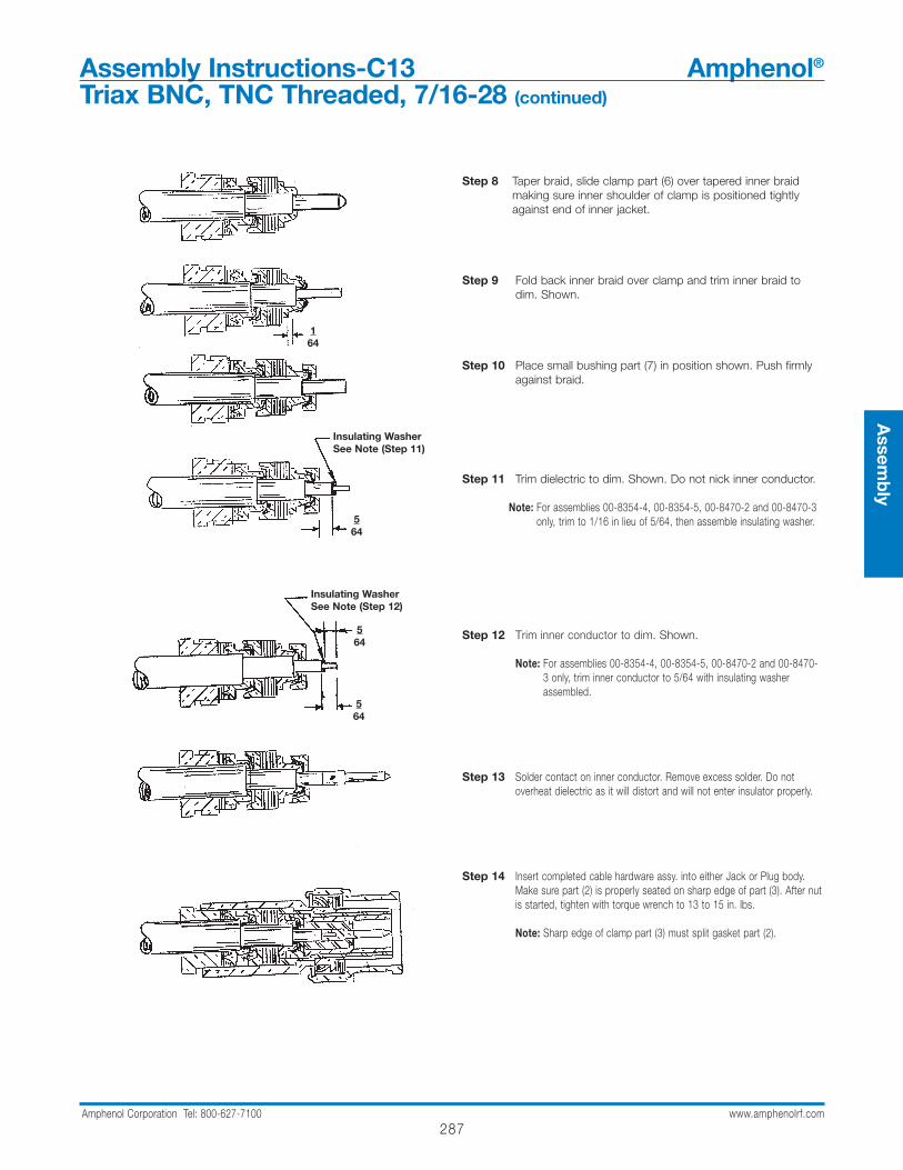
Step 8 Taper braid, slide clamp part (6) over tapered inner braidmaking sure inner shoulder of clamp is positioned tightlyagainst end of inner jacket.
Step 9 Fold back inner braid over clamp and trim inner braid todim. Shown.
Step 10 Place small bushing part (7) in position shown. Push firmlyagainst braid.
Step 11 Trim dielectric to dim. Shown. Do not nick inner conductor.
Note: For assemblies 00-8354-4, 00-8354-5, 00-8470-2 and 00-8470-3only, trim to 1/16 in lieu of 5/64, then assemble insulating washer.
Step 12 Trim inner conductor to dim. Shown.
Note: For assemblies 00-8354-4, 00-8354-5, 00-8470-2 and 00-8470-3 only, trim inner conductor to 5/64 with insulating washerassembled.
Step 13 Solder contact on inner conductor. Remove excess solder. Do not overheat dielectric as it will distort and will not enter insulator properly.
Step 14 Insert completed cable hardware assy. into either Jack or Plug body.Make sure part (2) is properly seated on sharp edge of part (3). After nutis started, tighten with torque wrench to 13 to 15 in. lbs.
Note: Sharp edge of clamp part (3) must split gasket part (2).
164
564
Insulating WasherSee Note (Step 11)
564
564
Insulating WasherSee Note (Step 12)

Assembly Instructions-C14 Amphenol®
Triax BNC & TNC Threaded, 7/16-28
ALTERNATE ASSEMBLY INSTRUCTIONS
Gasket (Part #2), Clamp (Part #3) & Bushing (Part #4) is replaced by washer (Part #12).
288Amphenol Corporation Tel: 800-627-7100 www.amphenolrf.com
Step 1A Cut off end of cable square and remove jacket to dim’sshown. Do not nick braid.
Step 2A Comb out braid.
Step 3A Taper braid, slide washer over braid and jacket.
Step 4A Trim braid to dim shown.
Step 5A Flare back braid to face of washer, and place gasket inposition shown.
Step 6A Remove inner jacket to dim shown.
Continue as per inst. #7 of sheet page 72
58
116
364
Nut Part 1
Washer Part 2
Gasket Part 3
289Amphenol Corporation Tel: 800-627-7100 www.amphenolrf.com
Assem
bly
Assembly Instructions-C15 Amphenol®
Triax Threaded, 7/8-20 and 11/16-24
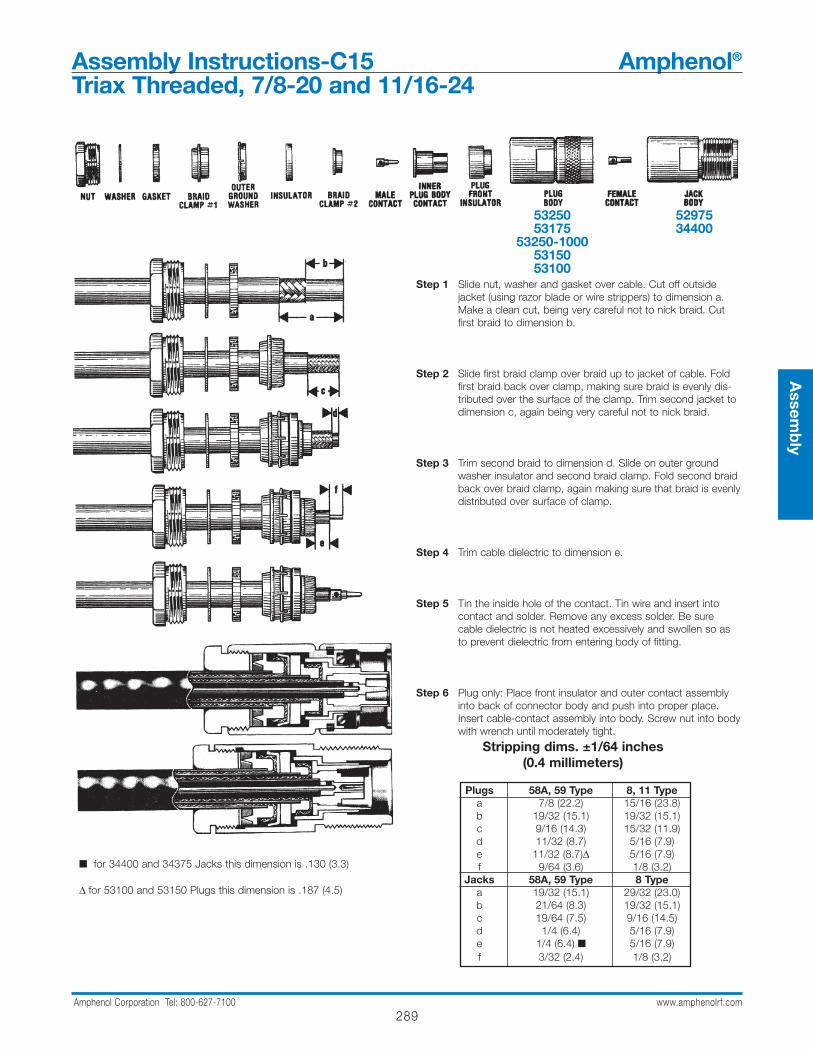
Step 1 Slide nut, washer and gasket over cable. Cut off outsidejacket (using razor blade or wire strippers) to dimension a.Make a clean cut, being very careful not to nick braid. Cutfirst braid to dimension b.
Step 2 Slide first braid clamp over braid up to jacket of cable. Foldfirst braid back over clamp, making sure braid is evenly dis-tributed over the surface of the clamp. Trim second jacket todimension c, again being very careful not to nick braid.
Step 3 Trim second braid to dimension d. Slide on outer groundwasher insulator and second braid clamp. Fold second braidback over braid clamp, again making sure that braid is evenlydistributed over surface of clamp.
Step 4 Trim cable dielectric to dimension e.
Step 5 Tin the inside hole of the contact. Tin wire and insert intocontact and solder. Remove any excess solder. Be surecable dielectric is not heated excessively and swollen so asto prevent dielectric from entering body of fitting.
Step 6 Plug only: Place front insulator and outer contact assemblyinto back of connector body and push into proper place.Insert cable-contact assembly into body. Screw nut into bodywith wrench until moderately tight.
Stripping dims. ±1/64 inches (0.4 millimeters)
Plugs 58A, 59 Type 8, 11 Typea 7/8 (22.2) 15/16 (23.8)b 19/32 (15.1) 19/32 (15.1)c 9/16 (14.3) 15/32 (11.9)d 11/32 (8.7) 5/16 (7.9)e 11/32 (8.7)∆ 5/16 (7.9)f 9/64 (3.6) 1/8 (3.2)
Jacks 58A, 59 Type 8 Typea 19/32 (15.1) 29/32 (23.0)b 21/64 (8.3) 19/32 (15.1)c 19/64 (7.5) 9/16 (14.5)d 1/4 (6.4) 5/16 (7.9)e 1/4 (6.4) 5/16 (7.9)f 3/32 (2.4) 1/8 (3.2)
for 34400 and 34375 Jacks this dimension is .130 (3.3)
∆ for 53100 and 53150 Plugs this dimension is .187 (4.5)
5325053175
53250-10005315053100
5297534400
Assembly Instructions-C16 Amphenol®
C - Two-Stud Bayonet Lock
290Amphenol Corporation Tel: 800-627-7100 www.amphenolrf.com
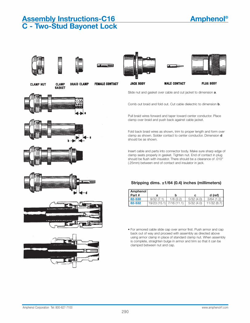
Slide nut and gasket over cable and cut jacket to dimension a.
Comb out braid and fold out. Cut cable dielectric to dimension b.
Pull braid wires forward and taper toward center conductor. Placeclamp over braid and push back against cable jacket.
Fold back braid wires as shown, trim to proper length and form overclamp as shown. Solder contact to center conductor. Dimension dshould be as shown.
Insert cable and parts into connector body. Make sure sharp edge ofclamp seats properly in gasket. Tighten nut. End of contact in plugshould be flush with insulator. There should be a clearance of .010"(.25mm) between end of contact and insulator in jack.
• For armored cable slide cap over armor first. Push armor and capback out of way and proceed with assembly as directed aboveusing armor clamp in place of standard clamp nut. When assemblyis complete, straighten bulge in armor and trim so that it can beclamped between nut and cap.
Stripping dims. ±1/64 (0.4) inches (millimeters)
AmphenolPart # a b c d (ref)82-530 9/32 (7.1) 1/8 (3.2) 5/32 (4.0) 3/64 (1.2)82-532 19/23 (15.1) 7/16 (11.1) 5/32 (4.0) 11/32 (8.7)

291Amphenol Corporation Tel: 800-627-7100 www.amphenolrf.com
Assem
bly
Assembly Instructions-C17 Amphenol®
HN - Typical Clamp
Place nut, gland, and gasket, with "V" groove toward nut, over cableand strip cable to dimensions as shown in table.
Comb out braid and fold out.
Pull braid wires forward and taper toward center conductor. Placeclamp over braid and push back against cable jacket.
Fold back braid wires as shown, trim to proper length and form overclamp as shown. Solder contact to center conductor.
Insert cable and parts into connector body, make sure sharp edge ofclamp seats properly in gasket. Tighten nut.Recommended Torque: 35-40 in lbs.
Nut Gland Gasket Clamp FemaleContact
B
C
A
Jack Body MaleContact
Plug Body
Stripping dims. inches (millimeters)AmphenolPart # a b c82-804 1.00 (25.4) .781 (19.8) .219 (5.6)82-856 .680 (17.3) .34 (8.6) .09 (2.3)82-324 1.59 (40.4) .875 (22.2) .718 (18.2)
Assembly Instructions-C18 Amphenol®
HN - Typical Clamp
292Amphenol Corporation Tel: 800-627-7100 www.amphenolrf.com
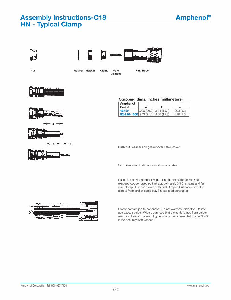
Push nut, washer and gasket over cable jacket.
Cut cable even to dimensions shown in table.
Push clamp over copper braid, flush against cable jacket. Cutexposed copper braid so that approximately 3/16 remains and fanover clamp. Trim braid even with end of taper. Cut cable dielectric(dim c) from end of cable cut. Tin exposed conductor.
Solder contact pin to conductor. Do not overheat dielectric. Do notuse excess solder. Wipe clean; see that dielectric is free from solder,resin and foreign material. Tighten nut to recommended torque 35-40in lbs securely with wrench.
Nut Washer Gasket Clamp MaleContact
Plug Body
a
b c
Stripping dims. inches (millimeters)AmphenolPart # a b c16750 .799 (20.2) .594 (15.1) .203 (5.8)82-816-1000 .843 (21.4) .625 (15.9) .218 (5.5)

293Amphenol Corporation Tel: 800-627-7100 www.amphenolrf.com
CLAMP PLUGS
Step 1
Step 2
Step 3
Step 4
Step 5
clamp clamp braid sleeve male insulator plug bodynut gasket clamp contacts 82-5589
82-5589-RFX32225
Step 1 Slide clamp nut and clamp gasket over cable end. V- groove in clamp gasket faces toward connector body. Strip cable to dimensions shown. Important: Do not nick insulation around center conductors. For solid core cables, lay braid back out of way while trimming core; then lay braid down again to facilitate Step 2.
Step 2 Slide braid clamp over braid until inner shoulder butts against jacket. (Note: sharp edge of braid clamp goes toward V-groove in clamp gasket.) Fold braid back evenly over braid clamp as shown.
Step 3 Slide sleeve over cable so that braid bottoms inside sleeve.Solder contacts to conductors, using minimum heat. Remove any excess solder. Alternative method: Crimp center contacts using CTL Series tool number CTL-4 cavities B & C; or by using Die Set 227-1414 cavities B & Cin tool frame 227-944 or in Pneumatic Crimp Tool 227-60.Bend conductors and contacts out and back to obtain .250(6.4) spacing between contacts.
Step 4 Insert contacts into rear of insulator. (Note: for Belden 9207and similar solid core cables, contact on bare copper conductor [or for Belden 8227 and similar air dielectric cables, the contact on white insulated conductor] goes into hole with dot next to it.) Slide insulator to butt against sleeve as shown.
Step 5 Insert assembly into connector body, aligning slot of insulator with polarizing key in body. Tighten clamp nut to 50 lbf-in.(5.7 N·m) torque. Do not twist connector body.
.370(9.5)Braid
.220(5.6)bare center conductors
for cables with foil,trim foil flush with jacket
.550(14.0)
.360(9.1)
for cables with filler, make surefiller is kept in center, do notmix filler in with braid
.250(6.4)
rear view of insulatorrear view of body
slot key
arrow or dot guidefor polarization
Assembly Instructions-C19 Amphenol®
Twinaxial
Assem
bly

294Amphenol Corporation Tel: 800-627-7100 www.amphenolrf.com
Assembly Instructions-C20 Amphenol®
HN - Typical Clamp
Cut end of cable even. Push nut, washer and gasket over cable jacket.
Remove vinyl jacket .798" (20.3) from end of cable. For double shieldcables, remove vinyl jacket 1 3/16" (30.2) from end of cable.
Push clamp over copper braid, flush against cable jacket. Cutexposed copper braid so that approximately .219" (5.6) remains andfan over clamp. Trim braid even with end of taper. Cut cable dielectricto Dim c.
Solder contact pin to conductor. Do not overheat dielectric. Do notuse excess solder. Wipe clean; see that dielectric is free from solder,resin and foreign material.
Taper dielectric with AMPHENOL 103-301 (MX-103/U) trimming tool.When tapering dielectric of cable for plug assembly, push contact stopof tool to bottom of slot. Tool will stop cutting when shoulder of con-tact butts against stop. Cable will be properly tapered when end ofcenter contact is flush with end of trimmer body.
Apply small amount of Dow Corning DC-4 Silicone Compound orequivalent (per MIL-S-8660) on tapered surface of dielectric. Insertassembly into connector body. Tighten nut securely with wrench.
Nut Washer Gasket Clamp MaleContact
Plug Body FemaleContact
Jack Body
a
bc
Stripping dims. inches (millimeters)AmphenolPart # a b c82-38 1.0 (25.4) .781 (19.8) .219 (5.6)
295Amphenol Corporation Tel: 800-627-7100 www.amphenolrf.com
Assem
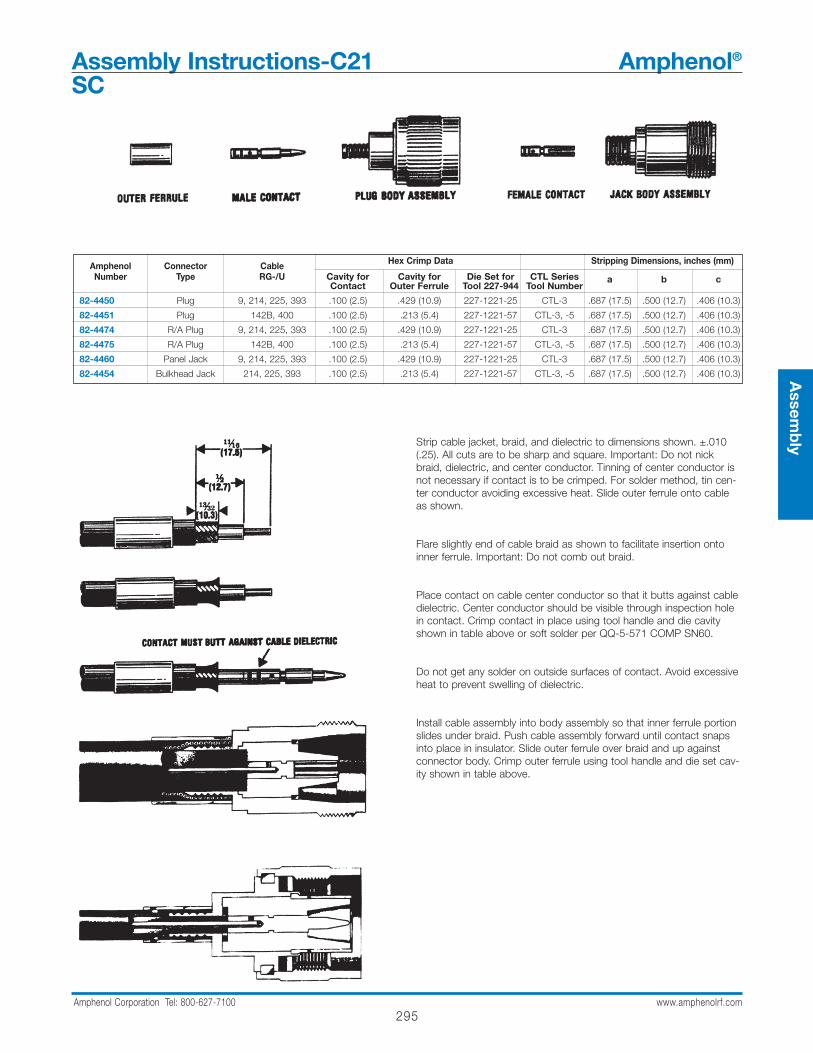
blyStrip cable jacket, braid, and dielectric to dimensions shown. ±.010
(.25). All cuts are to be sharp and square. Important: Do not nickbraid, dielectric, and center conductor. Tinning of center conductor isnot necessary if contact is to be crimped. For solder method, tin cen-ter conductor avoiding excessive heat. Slide outer ferrule onto cableas shown.
Flare slightly end of cable braid as shown to facilitate insertion ontoinner ferrule. Important: Do not comb out braid.
Place contact on cable center conductor so that it butts against cabledielectric. Center conductor should be visible through inspection holein contact. Crimp contact in place using tool handle and die cavityshown in table above or soft solder per QQ-5-571 COMP SN60.
Do not get any solder on outside surfaces of contact. Avoid excessiveheat to prevent swelling of dielectric.
Install cable assembly into body assembly so that inner ferrule portionslides under braid. Push cable assembly forward until contact snapsinto place in insulator. Slide outer ferrule over braid and up againstconnector body. Crimp outer ferrule using tool handle and die set cav-ity shown in table above.
Assembly Instructions-C21 Amphenol®
SC
Amphenol Connector Cable Hex Crimp Data Stripping Dimensions, inches (mm)
Number Type RG-/U Cavity for Cavity for Die Set for CTL SeriesContact Outer Ferrule Tool 227-944 Tool Number
a b c
82-4450 Plug 9, 214, 225, 393 .100 (2.5) .429 (10.9) 227-1221-25 CTL-3 .687 (17.5) .500 (12.7) .406 (10.3)
82-4451 Plug 142B, 400 .100 (2.5) .213 (5.4) 227-1221-57 CTL-3, -5 .687 (17.5) .500 (12.7) .406 (10.3)
82-4474 R/A Plug 9, 214, 225, 393 .100 (2.5) .429 (10.9) 227-1221-25 CTL-3 .687 (17.5) .500 (12.7) .406 (10.3)
82-4475 R/A Plug 142B, 400 .100 (2.5) .213 (5.4) 227-1221-57 CTL-3, -5 .687 (17.5) .500 (12.7) .406 (10.3)
82-4460 Panel Jack 9, 214, 225, 393 .100 (2.5) .429 (10.9) 227-1221-25 CTL-3 .687 (17.5) .500 (12.7) .406 (10.3)
82-4454 Bulkhead Jack 214, 225, 393 .100 (2.5) .213 (5.4) 227-1221-57 CTL-3, -5 .687 (17.5) .500 (12.7) .406 (10.3)

296Amphenol Corporation Tel: 800-627-7100 www.amphenolrf.com
Assembly Instructions-C22 Amphenol®
FME
Amphenol Connector Cable Hex Crimp Data Stripping Dimensions, inches (mm)
Number Type RG-/U Cavity for Cavity for Die Set for CTL SeriesContact Outer Ferrule Tool 227-944 Tool Number
a b c
81-169 Plug 58, 141, 142 .068 (1.7) .213 (5.3) 227-1221-11 CTL-1 .543 (13.8) .217 (5.5) .126 (3.2)
81-185-RFX Plug 174, 188, 316 .042 or Solder .128 (3.2) 227-1221-3 CTL-9 .465 (11.8) .209 (5.3) .091 (2.3)
81-160 Jack 58, 141, 142 .068 (1.7) .213 (5.3) 227-1221-11 CTL-1 .559 (14.2) .232 (5.9) .157 (4.0)
81-186-RFX Jack 58, 141, 142 .068 (1.7) .213 (5.3) 227-1221-11 CTL-1 .559 (14.2) .232 (5.9) .157 (4.0)
81-187-RFX Jack 174, 188, 316 .042 or Solder .128 (3.2) 227-1221-3 CTL-9 .469 (11.9) .201 (5.1) .118 (3.0)
Step 1 Place ferrule on cable as shown. Strip cable to dimensionsin table listed above.
Step 2 Crimp center contact to cable using tools listed in tableabove.
Step 3 Assemble body to cable. Contact must snap in place. Slideferrule over braid and crimp using tools listed in table above.
Step 1
Step 2
Step 3
CONNECTOR TERMINATION INSTRUCTIONS
297Amphenol Corporation Tel: 800-627-7100 www.amphenolrf.com
Assem
bly
Assembly Instructions-C23 Amphenol®
Triax C Bayonet Lock
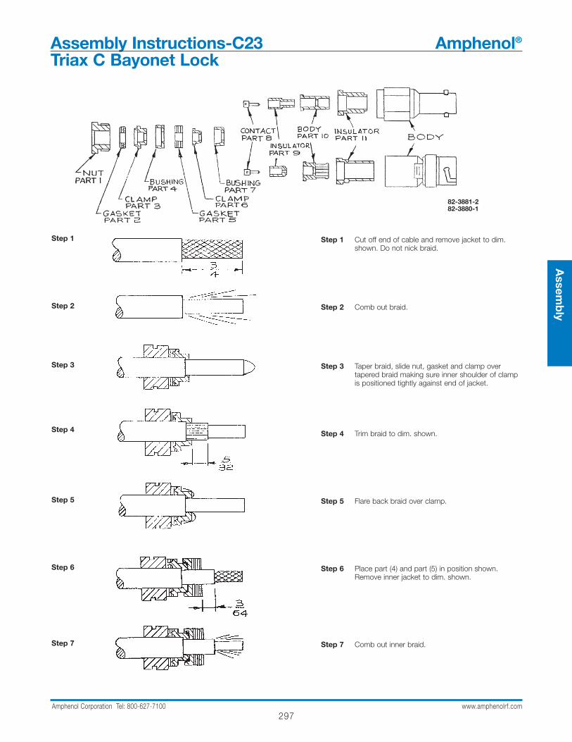
Step 1 Cut off end of cable and remove jacket to dim.shown. Do not nick braid.
Step 2 Comb out braid.
Step 3 Taper braid, slide nut, gasket and clamp overtapered braid making sure inner shoulder of clampis positioned tightly against end of jacket.
Step 4 Trim braid to dim. shown.
Step 5 Flare back braid over clamp.
Step 6 Place part (4) and part (5) in position shown.Remove inner jacket to dim. shown.
Step 7 Comb out inner braid.
82-3881-282-3880-1
Step 1
Step 2
Step 3
Step 4
Step 5
Step 6
Step 7

298Amphenol Corporation Tel: 800-627-7100 www.amphenolrf.com
Assembly Instructions-C23 Amphenol®
Triax C Bayonet Lock (continued)
Step 8 Taper braid, slide clamp part (6) over tapered innerbraid making sure inner shoulder of clamp is posi-tioned tightly against end of inner jacket.
Step 9 Fold back inner braid over clamp and trim innerbraid to dim. shown.
Step 10 Place small bushing part (7) in position shown.Push firmly against braid.
Step 11 Trim dielectric to dim. shown. Do not nick innerconductor.
Step 12 Trim inner conductor to dim. shown.
Step 13 Solder contact on inner conductor. Remove excesssolder. Do not overheat dielectric as it will distortand will not enter insulator properly.
Step 14 Insert complete cable hardware assembly intoeither Jack or Plug body. Make sure part (2) isproperly seated on sharp edge of part (3). After nut is started, tighten with torque wrench to 25 ± 5in. lbs.
Note: Sharp edge of clamp part (3) must split gasket part (2)
Step 8
Step 9
Step 10
Step 11
Step 12
Step 13
Step 14
299Amphenol Corporation Tel: 800-627-7100 www.amphenolrf.com
Assem
bly
CLAMP CONNECTORS
Step 1
Step 2
Step 3
Step 4
Step 5
For angle plugs only: (except 31-204) Solder center conductor to preassembled contact. Assemble cap and lightly punch center of cap for retention in body, or solder in place.
Step 1 Place nut, washer (when supplied) and gasket over cable and strip jacket to dimension a shown in table above.
Step 2 Comb out braid and fold out. Trim insulation off center conductor to dimension c shown in table above. [For RG-62,71 and 210/U cable, trim an additional .032"(0.8mm) of insulation off center conductor and add bushing.] Tin center conductor.
Step 3 Pull braid wires forward and taper toward center conductor.Place clamp over braid and push back against cable jacket.
Step 4 Fold back braid wires as shown, trim to proper length[approximately .125" (3.2mm) long] and form over clamp as shown. Braid wire should not extend beyond step of braid clamp. Solder contact to center conductor, sliding bushing first (when supplied) over center conductor.
Step 5 Insert cable and parts into connector body. Make suresharp edge of clamp seats properly in gasket. Tighten nutto approximately 15 inch pounds.
nut washer* gasket clamp bushing‡ female contact jack body male contact plug body
* Not supplied on all items ‡ For use on RG-62, 71, 122, 178, 180, 196, 210
Amphenol Connector CableStripping Dims,
Number Type RG-/UInches (Millimeters)
a c
6775 BNC Plug 8, 9, 11, 213, 214 .490(12.4) .200(5.1)
6775-75 75Ω BNC Plug 11 .490(12.4) .200(5.1)
8525 BNC Angle Plug 58, 141, 142, 400 .343(8.7) .187(4.7)
8575 BNC Angle Plug 59, 62, 140, 210 .297(7.5) .094(2.4)
9350 BNC Plug 6 .405(10.3) .094(2.4)
15875 BNC Plug 178, 196 .156(3.96) .078(1.98)
16300 BNC Plug 180 .250(6.4) .094(2.4)
33275 BNC Angle Plug 174, 179, 187, 188, 316 .540(13.7) .156(3.96)
69475 BNC Plug 174, 179, 187, 188, 316 .281(7.1) .172(4.4)
84975 BNC Plug 122 .281(7.1) .172(4.4)
86350 BNC Bulkh. Jack 174, 179, 187, 188, 316 .265(6.73) .156(3.96)
86425 BNC Panel Jack 174, 179, 187, 188, 316 .313(7.95) .203(5.15)
86850 BNC Bulkh. Jack 178, 196 .266(6.75) .109(2.76)
31-2 BNC Plug 58, 141, 142, 400 .312(7.9) .094(2.4)
31-2-RFX BNC Plug 58, 141, 142A .315(8.0) .118(3.0)
31-15 BNC Jack 59, 62, 71, 140, 210 .297(7.54) .109(2.75)
31-202 BNC Plug 55, 58, 141, 142, 223, 400 .274(6.95) .094(2.4)
31-204 BNC Angle Plug 55, 58, 141, 142, 223, 400 .297(7.54) .109(2.8)
31-206 BNC Bulkhead Jack 58, 141, 142, 400 .297(7.5) .109(2.8)
31-207 BNC Bulkhead Jack 59, 62, 71, 140, 210 .297(7.54) .109(2.75)
31-212 BNC Plug 59, 62, 71, 140, 210, 302 .250(6.4) .094(2.4)
31-212-1005 BNC Plug 59 (20GA CC) .250(6.4) .094(2.4)
31-850 BNC Angle Plug 59, 62, 71, 140, 210 .375(9.52) .125(3.17)
31-3202 BNC Plug 55, 58, 141, 142, 223, 400 .250(6.4) .094(2.4)
31-3301 BNC Plug 58, 141, 142, 223 .250(6.4) .094(2.4)
31-3302 BNC Plug 59, 62, 71, 140, 210 .250(6.4) .094(2.4)
a
c
Assembly Instructions-C25 Amphenol®
BNC

300Amphenol Corporation Tel: 800-627-7100 www.amphenolrf.com
3-PIECE CRIMP PLUGS
Amphenol Connector Cable Hex Crimp Data Stripping Dimensions, inches (mm)
Number Type RG-/U Cavity for Cavity for Die Set for CTL SeriesContact Outer Ferrule Tool 227-944* Tool Number
a b c
36650-1003 BNC PlugBelden 82907, 88240
.068(1.7) .178(4.5) 227-1221-9 CTL-2 .593(15.1) .250(6.4) .156(4.0)89907, Plenum 58
36650-3RFX BNC Plug Plenum 58 .068(1.7) .213(5.4) 227-1221-11 CTL-1 .630(16.0) .319(8.1) .157(4.0)
36875 BNC Plug 55, 142, 223, 400 .068(1.7) .213(5.4) 227-1221-11 CTL-1 .593(15.1) .250(6.4) .156(4.0)
68175-1003 BNC Plug Belden 9259 .068(1.7) .255(6.5) 227-1221-13 CTL-1 .593(15.1) .250(6.4) .156(4.0)
68175-1005 BNC Plug 59 (20AG CC) .068(1.7) .255(6.5) 227-1221-13 CTL-1 .593(15.1) .250(6.4) .156(4.0)
68175-1011 BNC PlugBelden 1560A, 82259,
.068(1.7) .255(6.5) 227-1221-13 CTL-1 .593(15.1) .250(6.4) .156(4.0)89259, Plenum 59, 62
68175-11RFX BNC Plug Plenum 59, 62 .068(1.7) .255(6.5) 227-1221-13 CTL-1 .630(16.0) .303(7.7) .157(4.0)
68175-5RFX BNC Plug 59 (20GA CC) .068(1.7) .255(6.5) 227-1221-13 CTL-1 .630(16.0) .303(7.7) .157(4.0)
31-242 BNC Plug 179, 187 .068(1.7) .178(4.5) 227-1221-9 CTL-2 .593(15.1) .250(6.4) .156(4.0)
31-242-RFX BNC Plug 179, 187 .068(1.7) .178(4.5) 227-1221-9 CTL-2 .590(15.0) .323(8.2) .118(3.0)
31-315 BNC Plug 174, 188, 316 .068(1.7) .178(4.5) 227-1221-9 CTL-2 .593(15.1) .250(6.4) .156(4.0)
31-315-RFX BNC Plug 174, 188, 316 .068(1.7) .178(4.5) 227-1221-9 CTL-2 .593(15.1) .250(6.4) .156(4.0)
31-315-1005 BNC Plug Dbl. Br. 316 .068(1.7) .178(4.5) 227-1221-9 CTL-2 .593(15.1) .250(6.4) .156(4.0)
31-320 BNC Plug 58, 141 .068(1.7) .213(5.4) 227-1221-11 CTL-1 .593(15.1) .250(6.4) .156(4.0)
31-320-RFX BNC Plug 58A, 141, 142A .068(1.7) .213(5.4) 227-1221-11 CTL-1 .630(16.0) .303(7.7) .156(4.0)
31-320-1006 BNC Plug Belden 9907, 89907 .068(1.7) .213(5.4) 227-1221-11 CTL-1 .593(15.1) .250(6.4) .156(4.0)
31-321 BNC Plug 59, 62 .068(1.7) .255(6.5) 227-1221-13 CTL-1 .593(15.1) .250(6.4) .156(4.0)
31-321-RFX BNC Plug 59, 62 .068(1.7) .255(6.5) 227-1221-13 CTL-1 .630(16.0) .303(7.7) .156(4.0)
31-321-1000 BNC Plug Belden 8281, 88281 .068(1.7) .324(8.2) 227-1221-32 CTL-2 .593(15.1) .250(6.4) .156(4.0)
31-321-10RFX BNC Plug Belden 8281 .068(1.7) .324(8.2) 227-1221-32 CTL-2 .630(16.0) .303(7.7) .156(4.0)
31-325 BNC Plug Belden 8218 .068(1.7) .178(4.5) 227-1221-9 CTL-2 .593(15.1) .250(6.4) .156(4.0)
31-326 BNC Plug 55, 142, 223 .068(1.7) .213(5.4) 227-1221-11 CTL-1 .593(15.1) .250(6.4) .156(4.0)
31-326-RFX BNC Plug 55, 142, 223, 400 .068(1.7) .213(5.4) 227-1221-11 CTL-1 .593(15.1) .250(6.4) .156(4.0)
31-4320 BNC Plug 58, 141 .068(1.7) .213(5.4) 227-1221-11 CTL-1 .593(15.1) .250(6.4) .156(4.0)
31-4321 BNC Plug 59, 62 .068(1.7) .255(6.5) 227-1221-13 CTL-1 .593(15.1) .250(6.4) .156(4.0)
31-4411 BNC Plug Belden 8213 .100(2.5) .429(10.9) 227-1221-25 CTL-3 .650(16.5) .250(6.4) .156(4.0)
31-4427 BNC Plug 142, 400 .068(1.7) .213(5.4) 227-1221-11 CTL-1 .593(15.1) .250(6.4) .156(4.0)
31-5558-RFX BNC Plug 6 Type (.314OD) .068(1.7) .324(8.2) 227-1221-32 CTL-2 .630(16.0) .303(7.7) .156(4.0)
31-5800 BNC Plug 58, 141, PL-58 .068(1.7) .213(5.4) 227-1221-11 CTL-1 .593(15.1) .250(6.4) .156(4.0)
31-5900 BNC Plug59, 62, 59 (20GA CC),
.068(1.7) .255(6.5) 227-1221-13 CTL-1 .593(15.1) .250(6.4) .156(4.0)Plenum -59, 62
* for pneumatic crimp tool 227-60, use die sets indicated in this column.
outer ferrule bushing male contact plug body assembly
used with RG-62, 71, 210 cable only
Assembly Instructions-C26 Amphenol®
BNC
For RG-174, 179, 187, 188, 316/U cables only, slit jacket back .100"(2.5mm) as shown. Before attaching center contact, slide metal spacer/TFE sleeve(not shown) over cable dielectric and under braid. The center contact should butt against the dielectric and TFE sleeve.
Step 1 Step 2 Step 3
contact must butt against cable dielectric
a
bc
Step 1 Strip cable jacket, braid, and dielec-tric to dimensions in table above. [for RG-62,71,210/U cable, trim an additional.039"(1.0mm) of insulation off center conduc-tor and add bushing] All cuts are to be sharpand square. Important: Do not nick braid, dielectric, andcenter conductor. Slide outer ferrule ontocable as shown.
Step 2 Flare slightly end of cable braid asshown to facilitate insertion of inner ferrule.Important: Do not comb out braid .Place contact on cable center conductor sothat it butts against cable dielectric. Crimpcontact in place using Die Set Cavity indicat-ed in table above. When using RG-62, 71,210 cable, install bushing over center con-ductor before installing contact.
Step 3 Install cable assembly into bodyassembly so that inner ferrule portion slidesunder braid. Push cable assembly forwarduntil contact snaps into place in insulator.Slide outer ferrule over braid and up againstconnector body. Crimp outer ferrule usingDie Set Cavity specified in table above.
cable dielectric must butt insulator
outer ferrule should butt here
crimp here

3-PIECE CRIMP ANGLE PLUGS & BULKHEAD JACKS
outer ferrule bushing male contact plug body assembly
used with RG-62, 71, 210 cable only
Step 1
For RG-174, 179, 187, 188, 316/U cables only, slit jacket back .100"(2.5mm) as shown. Before attaching center contact, slide metal spacer/TFE sleeve(not shown) over cable dielectric and under braid. The center contact should butt against the dielectric and TFE sleeve.
Step 2 contact must butt against cable dielectric
Step 3
a
bc
cable dielectric must butt insulator
outer ferrule should butt here
crimp here
301Amphenol Corporation Tel: 800-627-7100 www.amphenolrf.com
Assem
bly
Amphenol Connector Cable Hex Crimp Data Stripping Dimensions, inches (mm)
Number Type RG-/U Cavity for Cavity for Die Set for CTL SeriesContact Outer Ferrule Tool 227-944* Tool Number
a b c
36800 BNC Jack 58, 141 .068(1.7) .213(5.4) 227-1221-11 CTL-1 .593(15.1) .250(6.4) .156(4.0)36800-RFX BNC Jack 58, 141 .068(1.7) .213(5.4) 227-1221-11 CTL-1 .630(16.0) .303(7.7) .156(4.0)68150 BNC Jack 59, 62, 140 .068(1.7) .255(6.5) 227-1221-13 CTL-1 .593(15.1) .250(6.4) .156(4.0)95700 BNC Bulkh. Jack 55, 142, 223 .068(1.7) .213(5.4) 227-1221-11 CTL-1 .593(15.1) .250(6.4) .156(4.0)31-245 BNC Bulkh. Jack 179, 187 .068(1.7) .178(4.5) 227-1221-9 CTL-2 .593(15.1) .250(6.4) .156(4.0)31-316 BNC Angle Plug 174, 188, 316 .068(1.7) .178(4.5) 227-1221-9 CTL-2 .578(14.6) .328(8.3) .125(3.1)31-317 BNC Jack 174, 188, 316 .068(1.7) .178(4.5) 227-1221-9 CTL-2 .593(15.1) .250(6.4) .156(4.0)31-318 BNC Bulkh. Jack 174, 188, 316 .068(1.7) .178(4.5) 227-1221-9 CTL-2 .593(15.1) .250(6.4) .156(4.0)31-318-RFX BNC Bulkh. Jack 174, 188, 316 .068(1.7) .178(4.5) 227-1221-9 CTL-2 .630(16.0) .362(9.2) .156(4.0)31-318-1001 BNC Bulkh. Jack Dbl. Br. 316 .068(1.7) .178(4.5) 227-1221-9 CTL-2 .593(15.1) .250(6.4) .156(4.0)31-245-RFX BNC Bulkh. Jack 179, 187 .068(1.7) .178(4.5) 227-1221-9 CTL-2 .630(16.0) .362(9.2) .156(4.0)31-334 BNC Angle Plug 55, 142, 223, 400 .068(1.7) .213(5.4) 227-1221-11 CTL-1 .578(14.6) .328(8.3) .125(3.1)31-335 BNC Angle Plug 58, 141 .068(1.7) .213(5.4) 227-1221-11 CTL-1 .578(14.7) .328(8.3) .125(3.2)31-335-RFX BNC Angle Plug 58, 144 .068(1.7) .213(5.4) 227-1221-11 CTL-1 .677(17.2) .350(8.9) 156(4.0)31-336 BNC Angle Plug 59, 62 .068(1.7) .255(6.5) 227-1221-13 CTL-1 .578(14.7) .328(8.3) .125(3.2)31-336-RFX BNC Angle Plug 59, 62 .068(1.7) .255(6.5) 227-1221-13 CTL-1 .677(17.2) .350(8.9) .156(4.0)31-342 BNC Bulkh. Jack 58, 141 .068(1.7) .213(5.4) 227-1221-11 CTL-1 .593(15.1) .250(6.4) .156(4.0)31-342-RFX BNC Bulkh. Jack 58, 141, 142, 223 .068(1.7) .213(5.4) 227-1221-11 CTL-1 .689(17.5) .362(9.2) .157(4.0)31-343-1002 BNC Bulkh. Jack Pl. 59 (20 AWG) .068(1.7) .255(6.5) 227-1221-13 CTL-1 .593(15.1) .250(6.4) .156(4.0)31-343-RFX BNC Bulkh. Jack 59, 62, 140, 210 .068(1.7) .255(6.5) 227-1221-11 CTL-1 .689(17.5) .362(9.2) .157(4.0)31-4327 BNC Jack 58, 141 .068(1.7) .213(5.4) 227-1221-11 CTL-1 .593(15.1) .250(6.4) .156(4.0)31-5911-RFX BNC Angle Plug 58,141 Solder .213 227-1221-11 CTL-1,3,5 .709(18.0) .382(9.7) .161(4.1)31-5914-RFX BNC Angle Plug 59 Solder .255 227-1221-13 CTL-1,5,6,8 .709(18.0) .382(9.7) .161(4.1)31-5991-RFX BNC Angle Plug 316 Solder .128 227-1221-3 CTL-9,13 .618(15.7) .350(8.9) .157(4.0)31-316-RFX BNC Angle Plug 316 Solder .128 227-1221-3 CTL-9,13 .618(15.7) .350(8.9) .157(4.0)31-70239 BNC Angle Plug 734A .042 .255 — CTL-14 .630 (16.0) .303 (7.7) .157 (4.0)31-70240 BNC Angle Plug 735A .042 .187 — CTL-15 .630 (16.0) .303 (7.7) .157 (4.0)31-70234 BNC Plug Beld 1694 .042 .319 — CTL-14 .630 (16.0) .303 (7.7) .157 (4.0)31-70235 BNC Plug Beld 8281 .042 .324 — CTL-14 .630 (16.0) .303 (7.7) .157 (4.0)31-70236 BNC Plug Beld 8218 .042 .178 — CTL-15 .630 (16.0) .303 (7.7) .157 (4.0)31-70237 BNC Plug 734A .042 .255 — CTL-14 .630 (16.0) .303 (7.7) .157 (4.0)31-70238 BNC Plug 735A .042 .187 — CTL-15 .630 (16.0) .303 (7.7) .157 (4.0)31-315-RFX BNC Plug 174,188,316 .068 .178 227-1221-9 CTL-2 .593 (15.1) .250 (6.4) .156 (4.0)31-317-RFX BNC Jack 174,188,316 .068 .178 227-1221-9 CTL-2 .634 (16.1) .303 (7.7) .156 (4.0)31-335-RFX BNC Angle Plug 58,141,142 .068 .213 227-1221-11 CTL-1,5 .677 (17.2) .350 (8.9) .157 (4.0)31-5998-RFX BNC Plug B8214,B9913,B9914 .118 .429 227-1221-61 CTL-11 .630 (16) .303 (7.7) .157 (4.0)31-5999-RFX BNC Plug 8x,LMR240 .068 .255 227-1221-13 CTL-1,5 .630 (16) .303 (7.7) .157 (4.0)31-6004-RFX BNC Angle Plug B9913,B9914 Solder .429 227-1221-25 CTL-4 .728 (18.5) .401 (10.2) .244 (6.2)31-6005-RFX BNC Angle Plug 8x,LMR240 Solder .255 227-1221-13 CTL-1,5 .728 (18.5) .401 (10.2) .244 (6.2)31-6006 BNC Plug 8x,LMR240 .068 .255 227-1221-13 CTL-1,5 .593 (15.1) .250 (6.4) .156 (4.0)
Step 1 Strip cable jacket, braid, and dielectric to dimensions in table above. [forRG-62,71,210/U cable, trim an additional .039"(1.0mm) of insulation offcenter conductor and add bushing] All cuts are to be sharp and square.Important: Do not nick braid, dielectric, and center conductor. Slideouter ferrule onto cable as shown.
Step 2 Flare slightly end of cable braid as shown to facilitate insertion of inner fer-rule. Important: Do not comb out braid . Place contact on cable centerconductor so that it butts against cable dielectric. Crimp contact in placeusing Die Set Cavity indicated in table above. When using RG-62, 71,210 cable, install bushing onto center conductor before installing contact.
Step 3 Install cable assembly into body assembly so that inner ferrule portionslides under braid. Push cable assembly forward until contact snaps intoplace in insulator. Slide outer ferrule over braid and up against connectorbody. Crimp outer ferrule using Die Set Cavity specified in table above.
* for pneumatic crimp tool 227-60, use die sets indicated in this column
Assembly Instructions-C26a Amphenol®
BNC

302Amphenol Corporation Tel: 800-627-7100 www.amphenolrf.com
ORIGINAL CRIMP PLUGS
Step 1
Step 2
Step 3
Step 4
Step 5
Step 6
Step 7
Step 1 Install boot and slide outer ferrule onto cable as shown prior to stripping cable.
Step 2 Strip cable jacket, braid and dielectric to dimensions shown. See attached table for dimensions. All cuts are to be sharp and square. Important: DO NOT nick braid, dielectric, and center conductor when cutting. Tin center conductor using soft solder per QQ-S-571 comp Sn 60. Avoid excessive heat while tinning to prevent swelling of cable dielectric.
Step 3 Slightly flare out end of cable braid as so as to facilitate insertion onto ferrule clamp nut assembly. Important: DO NOT comb out braid.
Step 4 Install ferrule clamp nut assembly onto cable so that ferrule portion slides under braid and insulator butts flush against cable dielectric. Slide outer ferrule over braid and up against nut. Make sure no slack exists in braid. Crimp outer ferrule with tool specified in table above, keeping cable dielectric bottomed against insulator.
Step 5 Soft solder center conductor to contact using rosin core per QQ-S-571 comp Sn 60. DO NOT get any solder on outside surfaces of contact.
Step 6 Screw connector body onto prepared cable termination . Wrench tighten by holding the cable nut assembly STATIONARY while ROTATING the connector body.
Step 7 Push body forward and into position as shown to complete assembly.
Amphenol Connector Cable Hex Crimp Data Stripping Dimensions, inches (mm)
Number Type RG-/U Cavity for Cavity for Die Set forContact Outer Ferrule Tool 227-944*
a b c
31-351 BNC Plug 58, 141 — .213(5.4) 227-1221-11 .922(23.4) .516(13.1) .250(6.3)
31-359 BNC Plug 59, 62, 140 — .255(6.5) 227-1221-13 .922(23.4) .516(13.1) .250(6.3)
31-371 BNC Plug 174, 179, 187, 188, 316 — .128(3.2) 227-1221-3 .797(20.2) .516(13.1) .250(6.3)
boot ferrule ferrule clamp plug body assemblynut assembly
FERRULE/PLUG BODY ASSY
OUTER FERRULECLAMP NUT ASSY
BOOT
* for pneumatic crimp tool 227-60, use die sets indicated in this column
STEP 1
boot outer ferrule
STEP 2
STEP 4
STEP 5
P 3
STEP 6
STEP 7
outer ferrule mustclamp nut assy as shown
cable dielectric mustbutt insulator as shown
note: center conductor mustbe visible thru contact solderhole prior to soldering
lip of boot must be firmly posi-tioned in body groove
a
b
c
Assembly Instructions-C26b Amphenol®
BNC
303Amphenol Corporation Tel: 800-627-7100 www.amphenolrf.com
Assem
bly
Assembly Instructions-C28 Amphenol®
BNC
Step 1
Step 2
Step 3
Step 4
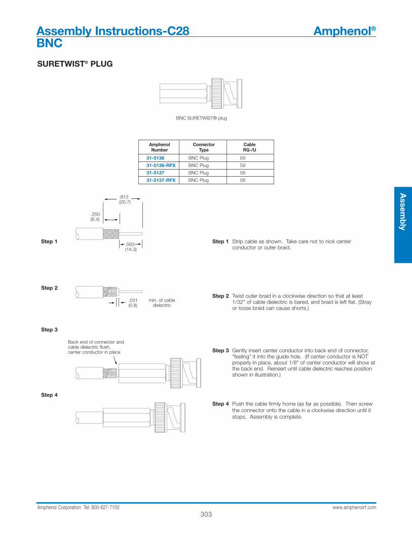
Step 1 Strip cable as shown. Take care not to nick center conductor or outer braid.
Step 2 Twist outer braid in a clockwise direction so that at least 1/32" of cable dielectric is bared, and braid is left flat. (Stray or loose braid can cause shorts.)
Step 3 Gently insert center conductor into back end of connector, "feeling" it into the guide hole. (If center conductor is NOT properly in place, about 1/8" of center conductor will show at the back end. Reinsert until cable dielectric reaches position shown in illustration.)
Step 4 Push the cable firmly home (as far as possible). Then screw the connector onto the cable in a clockwise direction until it stops. Assembly is complete.
BNC SURETWIST® plug
Amphenol Connector CableNumber Type RG-/U
31-5136 BNC Plug 59
31-5136-RFX BNC Plug 59
31-5137 BNC Plug 58
31-5137-RFX BNC Plug 58
.563(14.3)
.813(20.7)
.250(6.4)
min. of cabledielectric
.031(0.8)
Back end of connector andcable dielectric flush,center conductor in place
SURETWIST® PLUG

304Amphenol Corporation Tel: 800-627-7100 www.amphenolrf.com
Step 1A
Step 1B
Step 2
Step 3
Step 4
Step 1A For all connectors except 31-4541-RFX (see step 1B).Slide clamp nut over cable. Strip cable to dimension shown. Cut braid and dielectric square. Do not nick center conductor.
Step 1B For 31-4541-RFX.. Same as step 1A except use Step 1B strip dimensions, and then slit jacket back .125"(3.2 mm) in four places 90° apart as shown in illustration.
Step 2 Slide contact assembly under braid and jacket until braid butts as shown. Use caution that braid slides over contactassembly and not inside of it. Be sure center conductor is visible through side hole of contact. Solder contact to center conductor. Contact may be crimped on applicable connectors using Amphenol CTL-1 crimp tool; or by usingdie set 227-1221-13 cavity B in tool frame 227-944 or equivalent tool.
Step 3 Insert into connector body.
Step 4 Tighten clamp nut to a torque of 35 lbf-in.
clamp nut contact assembly plug body
Amphenol Connector Cable Center Contact Affixment
Number Type RG-/U Hex Size Die Set for CTL SeriesTool 227-944* Tool Number
31-4541 BNC Plug 59, 59A, 62, 62A31-4541-RFX
31-4542 BNC Plug Belden 9268 .068(1.7) 227-1221-13 CTL-1Montrose CBL-5098 Cavity B
31-30220-1 BNC Plug 58
31-30220-8 BNC Plug 223
* for pneumatic crimp tool 227-60, use die sets indicated in this column
.250(6.4)
.338(8.6)
.275(7.0).216 (5.5)
Assembly Instructions-C29 Amphenol®
BNC
QUICKTRIM® PLUG
305Amphenol Corporation Tel: 800-627-7100 www.amphenolrf.com
Assem
bly
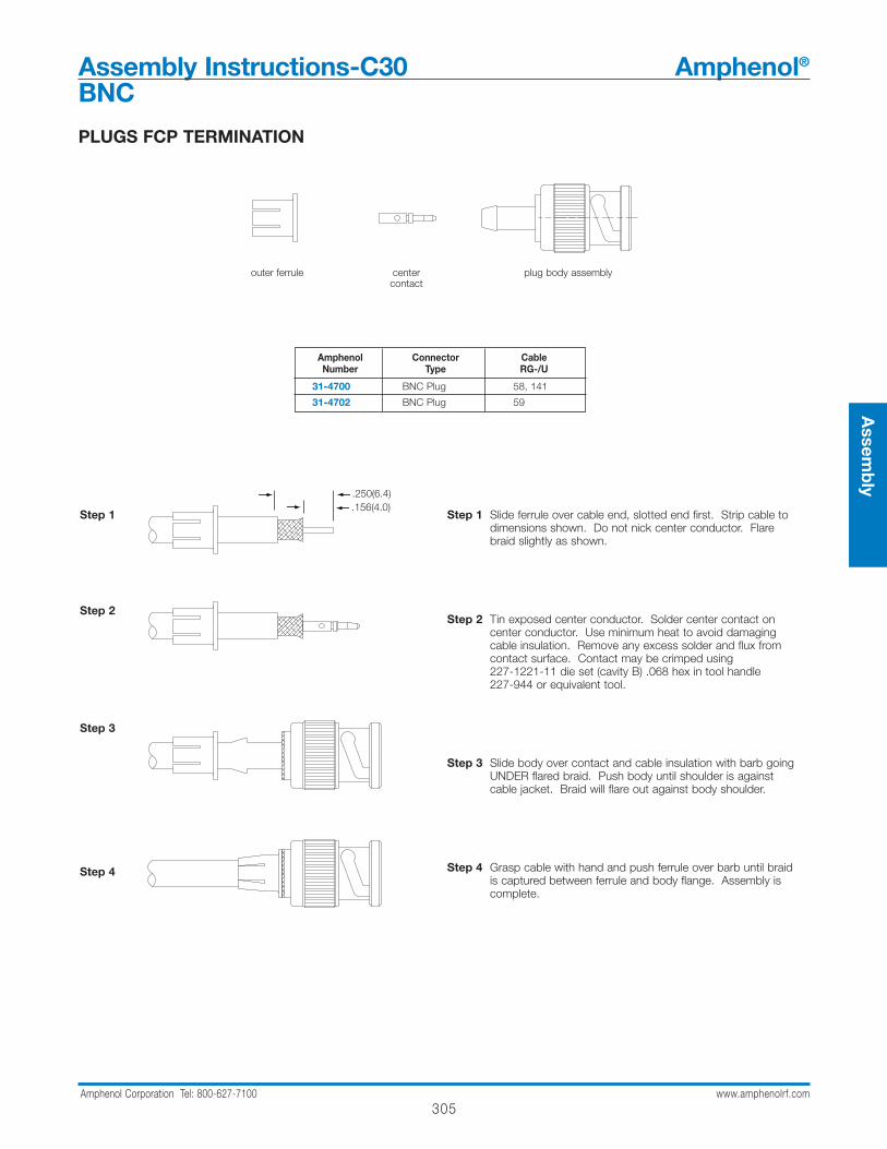
PLUGS FCP TERMINATION
Step 1
Step 2
Step 3
Step 4
Step 1 Slide ferrule over cable end, slotted end first. Strip cable to dimensions shown. Do not nick center conductor. Flare braid slightly as shown.
Step 2 Tin exposed center conductor. Solder center contact on center conductor. Use minimum heat to avoid damaging cable insulation. Remove any excess solder and flux from contact surface. Contact may be crimped using 227-1221-11 die set (cavity B) .068 hex in tool handle 227-944 or equivalent tool.
Step 3 Slide body over contact and cable insulation with barb going UNDER flared braid. Push body until shoulder is against cable jacket. Braid will flare out against body shoulder.
Step 4 Grasp cable with hand and push ferrule over barb until braid is captured between ferrule and body flange. Assembly is complete.
Amphenol Connector CableNumber Type RG-/U
31-4700 BNC Plug 58, 141
31-4702 BNC Plug 59
outer ferrule center plug body assemblycontact
.250(6.4)
.156(4.0)
Assembly Instructions-C30 Amphenol®
BNC
306Amphenol Corporation Tel: 800-627-7100 www.amphenolrf.com
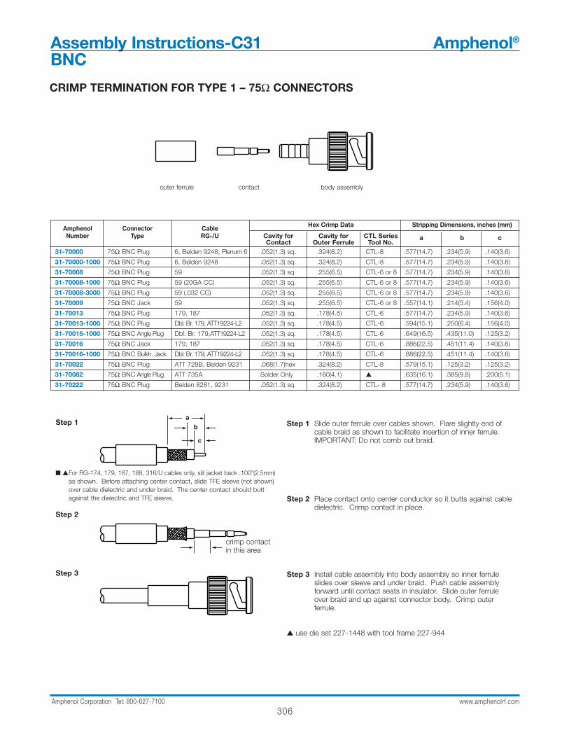
CRIMP TERMINATION FOR TYPE 1 – 75Ω CONNECTORS
Step 1
For RG-174, 179, 187, 188, 316/U cables only, slit jacket back .100"(2.5mm) as shown. Before attaching center contact, slide TFE sleeve (not shown)over cable dielectric and under braid. The center contact should buttagainst the dielectric and TFE sleeve.
Step 2
Step 3
Step 1 Slide outer ferrule over cables shown. Flare slightly end of cable braid as shown to facilitate insertion of inner ferrule. IMPORTANT: Do not comb out braid.
Step 2 Place contact onto center conductor so it butts against cable dielectric. Crimp contact in place.
Step 3 Install cable assembly into body assembly so inner ferrule slides over sleeve and under braid. Push cable assembly forward until contact seats in insulator. Slide outer ferrule over braid and up against connector body. Crimp outer ferrule.
use die set 227-1448 with tool frame 227-944
outer ferrule contact body assembly
Amphenol Connector Cable Hex Crimp Data Stripping Dimensions, inches (mm)
Number Type RG-/U Cavity for Cavity for CTL SeriesContact Outer Ferrule Tool No.
a b c
31-70000 75Ω BNC Plug 6, Belden 9248, Plenum 6 .052(1.3) sq. .324(8.2) CTL-8 .577(14.7) .234(5.9) .140(3.6)
31-70000-1000 75Ω BNC Plug 6, Belden 9248 .052(1.3) sq. .324(8.2) CTL-8 .577(14.7) .234(5.9) .140(3.6)
31-70008 75Ω BNC Plug 59 .052(1.3) sq. .255(6.5) CTL-6 or 8 .577(14.7) .234(5.9) .140(3.6)
31-70008-1000 75Ω BNC Plug 59 (20GA CC) .052(1.3) sq. .255(6.5) CTL-6 or 8 .577(14.7) .234(5.9) .140(3.6)
31-70008-3000 75Ω BNC Plug 59 (.032 CC) .052(1.3) sq. .255(6.5) CTL-6 or 8 .577(14.7) .234(5.9) .140(3.6)
31-70009 75Ω BNC Jack 59 .052(1.3) sq. .255(6.5) CTL-6 or 8 .557(14.1) .214(5.4) .156(4.0)
31-70013 75Ω BNC Plug 179, 187 .052(1.3) sq. .178(4.5) CTL-6 .577(14.7) .234(5.9) .140(3.6)
31-70013-1000 75Ω BNC Plug Dbl. Br. 179, ATT19224-L2 .052(1.3) sq. .178(4.5) CTL-6 .594(15.1) .250(6.4) .156(4.0)
31-70015-1000 75Ω BNC Angle Plug Dbl. Br. 179,ATT19224-L2 .052(1.3) sq. .178(4.5) CTL-6 .649(16.5) .435(11.0) .125(3.2)
31-70016 75Ω BNC Jack 179, 187 .052(1.3) sq. .178(4.5) CTL-6 .886(22.5) .451(11.4) .140(3.6)
31-70016-1000 75Ω BNC Bulkh. Jack Dbl. Br. 179, ATT19224-L2 .052(1.3) sq. .178(4.5) CTL-6 .886(22.5) .451(11.4) .140(3.6)
31-70022 75Ω BNC Plug ATT 728B, Belden 9231 .068(1.7)hex .324(8.2) CTL-8 .579(15.1) .125(3.2) .125(3.2)
31-70082 75Ω BNC Angle Plug ATT 735A Solder Only .160(4.1) .635(16.1) .385(9.8) .200(5.1)
31-70222 75Ω BNC Plug Belden 8281, 9231 .052(1.3) sq. .324(8.2) CTL- 8 .577(14.7) .234(5.9) .140(3.6)
a b
c
crimp contactin this area
Assembly Instructions-C31 Amphenol®
BNC
307Amphenol Corporation Tel: 800-627-7100 www.amphenolrf.com
Assem
bly
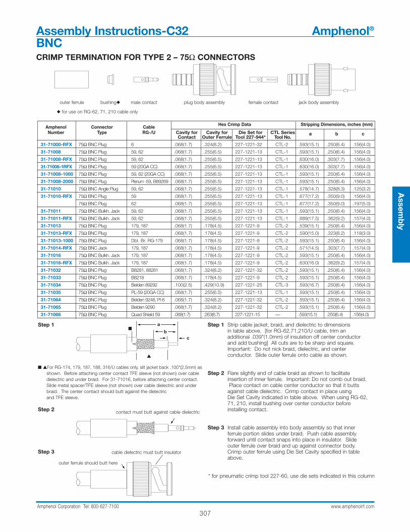
CRIMP TERMINATION FOR TYPE 2 – 75Ω CONNECTORS
Step 1 Strip cable jacket, braid, and dielectric to dimensionsin table above. [for RG-62,71,210/U cable, trim an additional .039"(1.0mm) of insulation off center conductor and add bushing] All cuts are to be sharp and square. Important: Do not nick braid, dielectric, and center conductor. Slide outer ferrule onto cable as shown.
Step 2 Flare slightly end of cable braid as shown to facilitate insertion of inner ferrule. Important: Do not comb out braid.Place contact on cable center conductor so that it butts
against cable dielectric. Crimp contact in place using Die Set Cavity indicated in table above. When using RG-62,71, 210, install bushing over center conductor before installing contact.
Step 3 Install cable assembly into body assembly so that inner ferrule portion slides under braid. Push cable assembly forward until contact snaps into place in insulator. Slide outer ferrule over braid and up against connector body. Crimp outer ferrule using Die Set Cavity specified in table above.
* for pneumatic crimp tool 227-60, use die sets indicated in this column
outer ferrule bushing male contact plug body assembly female contact jack body assembly
for use on RG-62, 71, 210 cable only
Step 1
For RG-174, 179, 187, 188, 316/U cables only, slit jacket back .100"(2.5mm) asshown. Before attaching center contact TFE sleeve (not shown) over cabledielectric and under braid. For 31-71016, before attaching center contact.Slide metal spacer/TFE sleeve (not shown) over cable dielectric and underbraid. The center contact should butt against the dielectric and TFE sleeve.
Step 2
Step 3
a
bc
contact must butt against cable dielectric
Amphenol Connector Cable Hex Crimp Data Stripping Dimensions, inches (mm)
Number Type RG-/U Cavity for Cavity for Die Set for CTL SeriesContact Outer Ferrule Tool 227-944* Tool No.
a b c
31-71000-RFX 75Ω BNC Plug 6 .068(1.7) .324(8.2) 227-1221-32 CTL-2 .593(15.1) .250(6.4) .156(4.0)
31-71008 75Ω BNC Plug 59, 62 .068(1.7) .255(6.5) 227-1221-13 CTL-1 .593(15.1) .250(6.4) .156(4.0)
31-71008-RFX 75Ω BNC Plug 59, 62 .068(1.7) .255(6.5) 227-1221-13 CTL-1 .630(16.0) .303(7.7) .156(4.0)
31-71008-1RFX 75Ω BNC Plug 59 (20GA CC) .068(1.7) .255(6.5) 227-1221-13 CTL-1 .630(16.0) .303(7.7) .156(4.0)
31-71008-1000 75Ω BNC Plug 59, 62 (20GA CC) .068(1.7) .255(6.5) 227-1221-13 CTL-1 .593(15.1) .250(6.4) .156(4.0)
31-71008-2000 75Ω BNC Plug Plenum -59, B89269 .068(1.7) .255(6.5) 227-1221-13 CTL-1 .593(15.1) .250(6.4) .156(4.0)
31-71010 75Ω BNC Angle Plug 59, 62 .068(1.7) .255(6.5) 227-1221-13 CTL-1 .578(14.7) .328(8.3) .125(3.2)
31-71010-RFX 75Ω BNC Plug 59 .068(1.7) .255(6.5) 227-1221-13 CTL-1 .677(17.2) .350(9.0) .156(4.0)
75Ω BNC Plug 62 .068(1.7) .255(6.5) 227-1221-13 CTL-1 .677(17.2) .350(9.0) .197(5.0)
31-71011 75Ω BNC Bulkh. Jack 59, 62 .068(1.7) .255(6.5) 227-1221-13 CTL-1 .593(15.1) .250(6.4) .156(4.0)
31-71011-RFX 75Ω BNC Bulkh. Jack 59, 62 .068(1.7) .255(6.5) 227-1221-13 CTL-1 .689(17.5) .362(9.2) .157(4.0)
31-71013 75Ω BNC Plug 179, 187 .068(1.7) .178(4.5) 227-1221-9 CTL-2 .539(15.1) .250(6.4) .156(4.0)
31-71013-RFX 75Ω BNC Plug 179, 187 .068(1.7) .178(4.5) 227-1221-9 CTL-2 .590(15.0) .323(8.2) .118(3.0)
31-71013-1000 75Ω BNC Plug Dbl. Br. RG-179 .068(1.7) .178(4.5) 227-1221-9 CTL-2 .593(15.1) .250(6.4) .156(4.0)
31-71014-RFX 75Ω BNC Jack 179, 187 .068(1.7) .178(4.5) 227-1221-9 CTL-2 .571(14.5) .303(7.7) .157(4.0)
31-71016 75Ω BNC Bulkh. Jack 179, 187 .068(1.7) .178(4.5) 227-1221-9 CTL-2 .593(15.1) .250(6.4) .156(4.0)
31-71016-RFX 75Ω BNC Bulkh. Jack 179, 187 .068(1.7) .178(4.5) 227-1221-9 CTL-2 .630(16.0) .362(9.2) .157(4.0)
31-71032 75Ω BNC Plug B8281, 88281 .068(1.7) .324(8.2) 227-1221-32 CTL-2 .593(15.1) .250(6.4) .156(4.0)
31-71033 75Ω BNC Plug B8218 .068(1.7) .178(4.5) 227-1221-9 CTL-2 .593(15.1) .250(6.4) .156(4.0)
31-71034 75Ω BNC Plug Belden 89292 .100(2.5) .429(10.9) 227-1221-25 CTL-3 .593(16.7) .250(6.4) .156(4.0)
31-71035 75Ω BNC Plug PL-59 (20GA CC) .068(1.7) .255(6.5) 227-1221-13 CTL-1 .593(15.1) .250(6.4) .156(4.0)
31-71064 75Ω BNC Plug Belden 9248, Pl-6 .068(1.7) .324(8.2) 227-1221-32 CTL-2 .593(15.1) .250(6.4) .156(4.0)
31-71065 75Ω BNC Plug Belden 9290 .068(1.7) .324(8.2) 227-1221-32 CTL-2 .593(15.1) .250(6.4) .156(4.0)
31-71066 75Ω BNC Plug Quad Shield 59 .068(1.7) .263(6.7) 227-1221-15 — .593(15.1) .250(6.4) .156(4.0)
outer ferrule should butt here
cable dielectric must butt insulator
Assembly Instructions-C32 Amphenol®
BNC

308Amphenol Corporation Tel: 800-627-7100 www.amphenolrf.com
CLAMP PLUGS
Step 1 Cut end of cable sharp and square. Slide clamp nut, washerand clamp gasket over jacket. Strip jacket to dimension shown. Comb out braid and fold out. Bare conductors to dimension shown.
Step 2 Pull braid forward and taper toward conductors. Slide braid clamp over braid as shown and push against cable jacket.
Step 3 Fold back braid, trim to proper length so no braid strands extend beyond shoulder of braid clamp and evenly form over braid clamp as shown. Slide on bushing. Tin center conductors using minimum amount of heat.
Step 4 Bend connectors out as necessary for alignment and slide on rear insulator. Solder contacts. Remove any excess solder from contact O.D.
Step 5 Slide front insulator over contacts and butt against contact shoulders as shown.
Step 6 Insert prepared cable termination into connector body. Make sure sharp edge of braid clamp seats properly in V-groove clamp gasket. Tighten securely, turning nut only. Do not twist connector body.
Step 1
Step 2
Step 3
Step 4
Step 5
Step 6
.172(4.4)
.375(9.5)
clampnut
washer clampgasket
braidclamp
bushing rearinsulator
frontinsulator
female/malecontacts
plug body31-224
31-2226
Assembly Instructions-C33 Amphenol®
Twin BNC
309Amphenol Corporation Tel: 800-627-7100 www.amphenolrf.com
Assem
bly
CLAMP TYPES
nut washer gasket clamp male bushing plug bodycontact
not supplied on all items
Step 1
Step 2
Step 3
Step 4
Amphenol Conn. Cable Stripping Dimensions,In.(mm)Number Type a c79075 TNC Angle Plug RG-58 .281(7.1) .109(2.8)
79875 TNC Plug RG-58 .281(7.1) .109(2.8)
79600 TNC Jack RG-58 .300(7.5) .110(2.8)
Step 1 Place nut, washer (when supplied) and gasket over cable and strip jacket to dimension a shown in table above.
Step 2 Comb out braid and fold out. Trim insulation off center conductor to dimension c shown in table above. Tin center conductor. Pull braid wires forward and taper toward center conductor. Place clamp over braid and push back against cable jacket.
Step 3 Fold back braid wires as shown, trim to proper length[.125" (3.2mm)] and form over clamp as shown. Solder contact to center conductor.
Step 4 Insert cable and parts into connector body. Make suresharp edge of clamp seats properly in gasket. Tighten nut.
B
A
1
2
3
4
STEP 5
a
c
Assembly Instructions-C34 Amphenol®
TNC

310Amphenol Corporation Tel: 800-627-7100 www.amphenolrf.com
CRIMP-CRIMP TYPES
Step 1
For RG-174, 179, 187, 188, 316/U cables only, slit jacket back .100"(2.5mm) as shown. Before attaching center contact, slide metal spacer/TFE sleeve (not shown) over cable dielectric. The center contact should butt against the dielectric and TFE sleeve.
Step 2
Step 3
Step 1 Strip cable jacket, braid, and dielectric to dimensionsin table above. All cuts are to be sharp and square. Important: Do not nick braid, dielectric, and center conductor. Slide outer ferrule onto cable as shown.
Step 2 Flare slightly end of cable braid as shown to facilitate insertion of inner ferrule. Important: Do not comb out braid.Place contact on cable center conductor so that it butts against cable dielectric. Crimp contact in place usingDie Set Cavity indicated in table above.
Step 3 Install cable assembly into body assembly so that inner ferrule portion slides under braid. Push cable assembly forward until contact snaps into place in insulator. Slide outer ferrule over braid and up against connector body. Crimp outer ferrule using Die Set Cavity in table above.
outer ferrule bushing male contact plug body assembly This part is used only with RG-62 cable
Amphenol Connector Cable Hex Crimp Data Stripping Dimensions, inches (mm)
Number Type RG-/U Cavity for Cavity for Die Set for CTL SeriesContact Outer Ferrule Tool 227-944 Tool No.
a b c
36825 TNC Plug 58, 141 .068(1.7) .213(5.4) 227-1221-11 CTL-1 .593(15.1) .250(6.4) .156(4.0)
31-2318 TNC Bulkh. Jack 174, 188, 316 .068(1.7) .178(4.5) 227-1221-09 CTL-2 .593(15.1) .250(6.4) .156(4.0)
31-2367 TNC Plug 58, 141 .068(1.7) .213(5.4) 227-1221-11 CTL-1 .593(15.1) .250(6.4) .156(4.0)
31-2367-RFX TNC Plug 58, 141, 142A .068(1.7) .213(5.4) 227-1221-11 CTL-1 .630(16.0) .303(7.7) .156(4.0)
31-2368 TNC Plug 59, 62 .068(1.7) .255(6.5) 227-1221-13 CTL-1 .593(15.1) .250(6.4) .156(4.0)
31-2373 TNC Plug 55, 142, 223 .068(1.7) .213(5.4) 227-1221-11 CTL-1 .593(15.1) .250(6.4) .156(4.0)
31-2381 TNC Angle Plug 55, 142, 223, 400 .068(1.7) .213(5.4) 227-1221-11 CTL-1 .578(14.7) .328(8.3) .125(3.2)
31-4452 TNC Plug 142, 400 .068(1.7) .213(5.4) 227-1221-11 CTL-1 .593(15.1) .250(6.4) .156(4.0)
31-2242 TNC Plug 179,187 .068 (1.7) .178 (4.5) 227-1221-09 CTL-2 .593(15.1) .250(6.4) .156(4.0)
31-2242-RFX TNC Plug 179,187 .068 (1.7) .178 (4.5) 227-1221-09 CTL-2 .590(15.0) .323(8.2) .118(3.0)
31-2264 TNC Blkh Jack 59,62,140,210 .068 (1.7) .255 (8.5) 227-1221-13 CTL-1 .593(15.1) .250(6.4) .156(4.0)
31-2264-RFX TNC Blkh Jack 59 .068 (1.7) .255 (8.5) 227-1331-13 CTL-1 .689(17.5) .362(9.2) .157(4.0)
31-2264-RFX TNC Blkh Jack 62 .068 (1.7) .255 (8.5) 227-1331-13 CTL-1 .689(17.5) .362(9.2) .197(5.0)
31-2315 TNC Plug 174,188 .068 (1.7) .178 (4.5) 227-1221-09 CTL-2 .593(15.1) .250(6.4) .156(4.0)
31-2315-RFX TNC Plug 174,188,316 .068 (1.7) .178 (4.5) 227-1221-09 CTL-2 .590(15.0) .323(8.2) .118(3.0)
31-2317 TNC Jack 174.188 .068 (1.7) .178 (4.5) 227-1221-09 CTL-2 .590(15.0) .323(8.2) .118(3.0)
31-2318 TNC Blkh Jack 174,187,188 .068 (1.7) .178 (4.5) 227-1221-09 CTL-2 .590(15.0) .323(8.2) .118(3.0)
31-2368-RFX TNC Plug 59 .068 (1.7) .255 (8.5) 227-1221-13 CTL-1 .630(16.0) .303(7.7) .157(4.0)
31-2368-RFX TNC Plug 62 .068 (1.7) .255 (8.5) 227-1221-13 CTL-1 .630(16.0) .303(7.7) .197(5.0)
31-2381 TNC Angle Plug 55,142 .068 (1.7) .213 (5.4) 227-1221-11 CTL-1 .578(14.7) .328(8.3) .125(3.2)
31-2382 TNC Angle Plug 58,141 .068 (1.7) .213 (5.4) 227-1221-11 CTL-1 .578(14.7) .328(8.3) .125(3.2)
31-2383 TNC Angle Plug 62 .068 (1.7) .255 (8.5) 227-1221-13 CTL-1 .689(17.5) .362(9.2) .156(4.0)
31-2389 TNC Blkh Jack 58,141 .068 (1.7) .213 (5.4) 227-1221-11 CTL-1 .593(15.1) .250(6.4) .156(4.0)
31-2389-RFX TNC Blkh Jack 141,142 .068 (1.7) .213 (5.4) 227-1221-11 CTL-1 .689(17.5) .362(9.2) .157(4.0)
31-2367-RFX TNC Plug 58,141 .068 .213 227-1221-11 CTL-1,5 .630 (16.0) .303 (7.7) .157 (4.0)
31-5849-RFX TNC Angle Plug 58,58c Solder .213 227-1221-11 CTL-1,3,5 .709(18) .382(9.7) .161(4.1)
31-6000-RFX TNC Plug 8x,LMR240 .068 .255 227-1221-13 CTL-1,5 .630 (16) .303 (7.7) .157 (4.0)
31-6001-RFX TNC Plug B8214, B9913 Solder .429 227-1221-25 CTL-4 .630 (16) .303 (7.7) .157 (4.0)
31-6002-RFX TNC Angle Plug LMR 400, B9913,B9914 Solder .429 227-1221-25 CTL-4 .728 (18.5) .401 (0.2) .244 (6.2)
31-6003-RFX TNC Angle Plug 8x,LMR240 Solder .255 227-1221-13 CTL-1,5 .728 (18.5) .401 (10.2) .244 (6.2)
A
B
C
STEP 1
STEP 2
STEP 3
contact must butt against cable dielectric
cable dielectric must butt insulatorouter ferrule should butt here
ab
c
Assembly Instructions-C36 Amphenol®
TNC
311Amphenol Corporation Tel: 800-627-7100 www.amphenolrf.com
Assem
bly
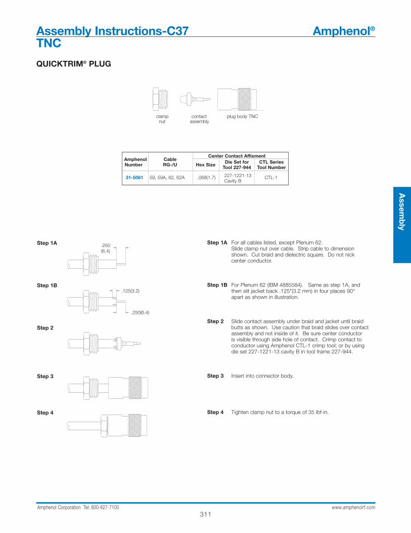
Assembly Instructions-C37 Amphenol®
TNC
Step 1A
Step 1B
Step 2
Step 3
Step 4
Step 1A For all cables listed, except Plenum 62.Slide clamp nut over cable. Strip cable to dimension shown. Cut braid and dielectric square. Do not nick center conductor.
Step 1B For Plenum 62 (IBM 4885584). Same as step 1A, and then slit jacket back .125"(3.2 mm) in four places 90°apart as shown in illustration.
Step 2 Slide contact assembly under braid and jacket until braid butts as shown. Use caution that braid slides over contactassembly and not inside of it. Be sure center conductor is visible through side hole of contact. Crimp contact to conductor using Amphenol CTL-1 crimp tool; or by usingdie set 227-1221-13 cavity B in tool frame 227-944.
Step 3 Insert into connector body.
Step 4 Tighten clamp nut to a torque of 35 lbf-in.
clamp contact plug body TNCnut assembly
Amphenol CableCenter Contact Affixment
Number RG-/U Hex Size Die Set for CTL SeriesTool 227-944 Tool Number
31-5061 59, 59A, 62, 62A .068(1.7) 227-1221-13 CTL-1Cavity B
.250 (6.4)
STEP 1A
.250 (6.4)
.125 (3.2)STEP 1B
STEP 4
STEP 2
STEP 3
.250(6.4)
.125(3.2)
.250(6.4)
QUICKTRIM® PLUG
312Amphenol Corporation Tel: 800-627-7100 www.amphenolrf.com
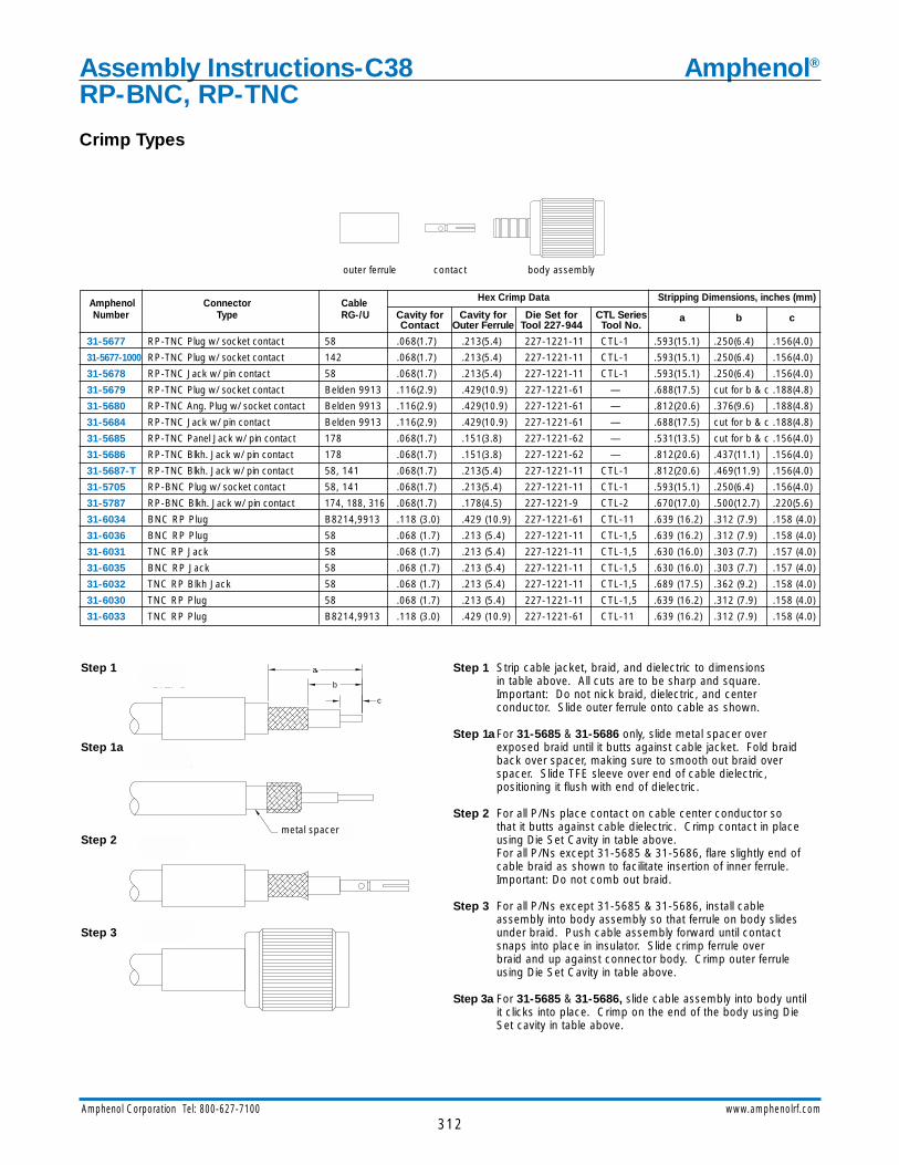
Assembly Instructions-C38 Amphenol®
RP-BNC, RP-TNC
Step 1
Step 1a
Step 2
Step 3
Step 1 Strip cable jacket, braid, and dielectric to dimensionsin table above. All cuts are to be sharp and square. Important: Do not nick braid, dielectric, and center conductor. Slide outer ferrule onto cable as shown.
Step 1aFor 31-5685 & 31-5686 only, slide metal spacer over exposed braid until it butts against cable jacket. Fold braid back over spacer, making sure to smooth out braid over spacer. Slide TFE sleeve over end of cable dielectric, positioning it flush with end of dielectric.
Step 2 For all P/Ns place contact on cable center conductor so that it butts against cable dielectric. Crimp contact in place using Die Set Cavity in table above.For all P/Ns except 31-5685 & 31-5686, flare slightly end of cable braid as shown to facilitate insertion of inner ferrule. Important: Do not comb out braid.
Step 3 For all P/Ns except 31-5685 & 31-5686, install cable assembly into body assembly so that ferrule on body slides under braid. Push cable assembly forward until contact snaps into place in insulator. Slide crimp ferrule over braid and up against connector body. Crimp outer ferrule using Die Set Cavity in table above.
Step 3a For 31-5685 & 31-5686, slide cable assembly into body until it clicks into place. Crimp on the end of the body using Die Set cavity in table above.
a
b
c
STEP 2
STEP 3
STEP 1
SPACER
STEP 1A
outer ferrule contact body assembly
Amphenol Connector Cable Hex Crimp Data Stripping Dimensions, inches (mm)
Number Type RG-/U Cavity for Cavity for Die Set for CTL SeriesContact Outer Ferrule Tool 227-944 Tool No.
a b c
31-5677 RP-TNC Plug w/ socket contact 58 .068(1.7) .213(5.4) 227-1221-11 CTL-1 .593(15.1) .250(6.4) .156(4.0)
31-5677-1000 RP-TNC Plug w/ socket contact 142 .068(1.7) .213(5.4) 227-1221-11 CTL-1 .593(15.1) .250(6.4) .156(4.0)
31-5678 RP-TNC Jack w/ pin contact 58 .068(1.7) .213(5.4) 227-1221-11 CTL-1 .593(15.1) .250(6.4) .156(4.0)
31-5679 RP-TNC Plug w/ socket contact Belden 9913 .116(2.9) .429(10.9) 227-1221-61 — .688(17.5) cut for b & c .188(4.8)
31-5680 RP-TNC Ang. Plug w/ socket contact Belden 9913 .116(2.9) .429(10.9) 227-1221-61 — .812(20.6) .376(9.6) .188(4.8)
31-5684 RP-TNC Jack w/ pin contact Belden 9913 .116(2.9) .429(10.9) 227-1221-61 — .688(17.5) cut for b & c .188(4.8)
31-5685 RP-TNC Panel Jack w/ pin contact 178 .068(1.7) .151(3.8) 227-1221-62 — .531(13.5) cut for b & c .156(4.0)
31-5686 RP-TNC Blkh. Jack w/ pin contact 178 .068(1.7) .151(3.8) 227-1221-62 — .812(20.6) .437(11.1) .156(4.0)
31-5687-T RP-TNC Blkh. Jack w/ pin contact 58, 141 .068(1.7) .213(5.4) 227-1221-11 CTL-1 .812(20.6) .469(11.9) .156(4.0)
31-5705 RP-BNC Plug w/ socket contact 58, 141 .068(1.7) .213(5.4) 227-1221-11 CTL-1 .593(15.1) .250(6.4) .156(4.0)
31-5787 RP-BNC Blkh. Jack w/ pin contact 174, 188, 316 .068(1.7) .178(4.5) 227-1221-9 CTL-2 .670(17.0) .500(12.7) .220(5.6)
31-6034 BNC RP Plug B8214,9913 .118 (3.0) .429 (10.9) 227-1221-61 CTL-11 .639 (16.2) .312 (7.9) .158 (4.0)
31-6036 BNC RP Plug 58 .068 (1.7) .213 (5.4) 227-1221-11 CTL-1,5 .639 (16.2) .312 (7.9) .158 (4.0)
31-6031 TNC RP Jack 58 .068 (1.7) .213 (5.4) 227-1221-11 CTL-1,5 .630 (16.0) .303 (7.7) .157 (4.0)
31-6035 BNC RP Jack 58 .068 (1.7) .213 (5.4) 227-1221-11 CTL-1,5 .630 (16.0) .303 (7.7) .157 (4.0)
31-6032 TNC RP Blkh Jack 58 .068 (1.7) .213 (5.4) 227-1221-11 CTL-1,5 .689 (17.5) .362 (9.2) .158 (4.0)
31-6030 TNC RP Plug 58 .068 (1.7) .213 (5.4) 227-1221-11 CTL-1,5 .639 (16.2) .312 (7.9) .158 (4.0)
31-6033 TNC RP Plug B8214,9913 .118 (3.0) .429 (10.9) 227-1221-61 CTL-11 .639 (16.2) .312 (7.9) .158 (4.0)
metal spacer
Crimp Types

313Amphenol Corporation Tel: 800-627-7100 www.amphenolrf.com
Assem
bly
CRIMP-CRIMP TYPE
Step 1
Step 2
Step 3
Step 4
Step 1 Strip cable to dimensions shown in table. All cuts are to be sharp and square. Important: do not nick braid, dielectric, or center conductor.
Step 2 Slide outer ferrule onto cable as shown. (For straight plugs, slide coupling nut onto cable, keeping the open end of the nut toward the stripped end of the cable.) Flare slightly end of cable braid as shown to facilitate insertion of inner ferrule. Important: Do not comb out braid.Place contact on cable center conductor so it butts against cable dielectric. Crimp contact in place using Tool Handle and Die Set Cavity shown in table above orsoft solder per QQ-S-571 comp. Sn60.
Step 3 Install cable assembly into body assembly so inner ferrule portion slides under braid. Push cable assembly forward until cable dielectric seats against connector insulator.
Step 4 (For straight plugs, slide coupling nut forward over body assembly as shown.)Slide outer ferrule over braid and up against connector body,holding connector body firmly in place. Crimp outer ferrule using Tool Handle and Die Set Cavity shown in table above.
outer male coupling plug body female jack body ferrule contact nut assembly contact assembly
Amphenol Strip Dimensions, Crimp Data
NumberConnector Cable
inches (mm) Cavity for Cavity for Die Set for CTL SeriesType RG-/Ua b c Contact Outer Ferrule Tool 227-944 Tool Number
81-114-RFX Mini-UHF Plug B 9258 .629(16.0) .302(7.7) .157(4.0) .068(1.7) .255(6.5) 227-1221-13 CTL-1, -5, -6
81-115BK-1000 Mini-UHF Plug 58 .593(15.1) .218(5.5) .218(5.5) .052(1.3) Sq. .213(5.4) 227-1409 CTL-5
81-115N-1000 Mini-UHF Plug 58 .593(15.1) .218(5.5) .218(5.5) .052(1.3) Sq. .213(5.4) 227-1409 CTL-5
81-116 Mini-UHF Jack 58 .500(12.7) .219(5.5) .219(5.5) .052(1.3) Sq. .213(5.4) 227-1409 CTL-5
81-182-RFX Mini-UHF Jack 59 .62515.9) .299(7.6) ..236(6) .068(1.7) Sq. .255(6.5) 227-1221-13 CTL-1, -5, -6
81-183-RFX Mini-UHF Jack 58/u58b/u .661(16.8) .334(8.5) .118(3) .068(1.7) Sq. .213(5.4) 227-1221-11 CTL-1, -5, -6
81-181-RFX Mini-UHF Plug 59 .937(23.8) .610(15.5) .492(12.5) .068(1.7) .255(6.5) 227-1221-13 CTL-1,-5,-6
81-196-RFX Mini-UHF Plug 58C, 58 .937(23.8) .610(15.5) .492(12.5) .068(1.7) .213(5.4) 227-1221-11 CTL-1,-5,-6
ab
Assembly Instructions-C39 Amphenol®
Mini-UHF
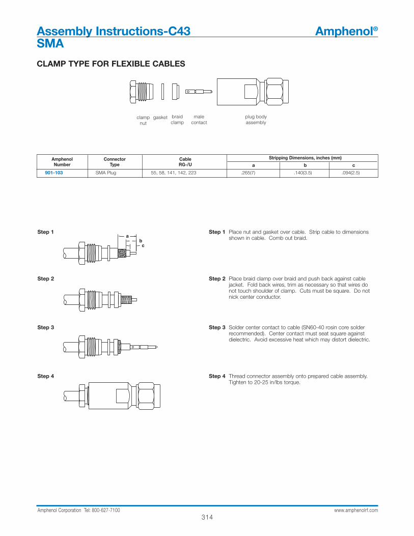
314Amphenol Corporation Tel: 800-627-7100 www.amphenolrf.com
Assembly Instructions-C43 Amphenol®
SMA
Step 1 Place nut and gasket over cable. Strip cable to dimensions shown in cable. Comb out braid.
Step 2 Place braid clamp over braid and push back against cable jacket. Fold back wires, trim as necessary so that wires do not touch shoulder of clamp. Cuts must be square. Do not nick center conductor.
Step 3 Solder center contact to cable (SN60-40 rosin core solder recommended). Center contact must seat square against dielectric. Avoid excessive heat which may distort dielectric.
Step 4 Thread connector assembly onto prepared cable assembly. Tighten to 20-25 in/lbs torque.
Amphenol Connector Cable Stripping Dimensions, inches (mm)Number Type RG-/U a b c
901-103 SMA Plug 55, 58, 141, 142, 223 .265(7) .140(3.5) .094(2.5)
braidclamp
plug body assembly
male contact
gasketclamp nut
abc
Step 1
Step 2
Step 3
Step 4
CLAMP TYPE FOR FLEXIBLE CABLES
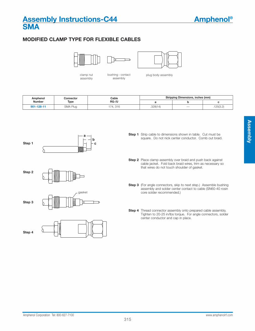
315Amphenol Corporation Tel: 800-627-7100 www.amphenolrf.com
Assem
bly
Assembly Instructions-C44 Amphenol®
SMA
Amphenol Connector Cable Stripping Dimensions, inches (mm)Number Type RG-/U a b c
901-128-11 SMA Plug 174, 316 .328(14) — .125(3.2)
plug body assemblyclamp nut assembly
bushing - contactassembly
Step 1
Step 2
Step 3
Step 4
MODIFIED CLAMP TYPE FOR FLEXIBLE CABLES
abc
gasket
Step 1 Strip cable to dimensions shown in table. Cut must be square. Do not nick center conductor. Comb out braid.
Step 2 Place clamp assembly over braid and push back against cable jacket. Fold back braid wires, trim as necessary so that wires do not touch shoulder of gasket.
Step 3 (For angle connectors, skip to next step.) Assemble bushing assembly and solder center contact to cable (SN60-40 rosin core solder recommended.)
Step 4 Thread connector assembly onto prepared cable assembly. Tighten to 20-25 in/lbs torque. For angle connectors, solder center conductor and cap in place.
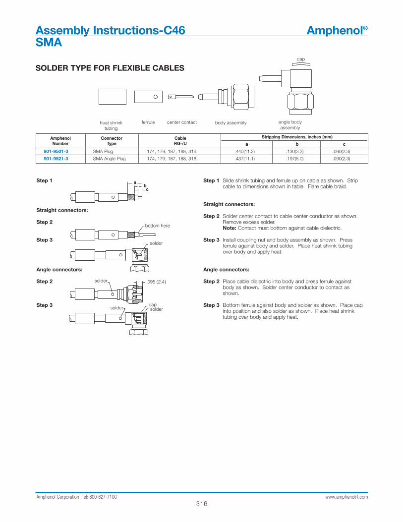
316Amphenol Corporation Tel: 800-627-7100 www.amphenolrf.com
Step 1
Straight connectors:
Step 2
Step 3
Angle connectors:
Step 2
Step 3
Step 1 Slide shrink tubing and ferrule up on cable as shown. Strip cable to dimensions shown in table. Flare cable braid.
Straight connectors:
Step 2 Solder center contact to cable center conductor as shown. Remove excess solder. Note: Contact must bottom against cable dielectric.
Step 3 Install coupling nut and body assembly as shown. Press ferrule against body and solder. Place heat shrink tubing over body and apply heat.
Angle connectors:
Step 2 Place cable dielectric into body and press ferrule against body as shown. Solder center conductor to contact as shown.
Step 3 Bottom ferrule against body and solder as shown. Place cap into position and also solder as shown. Place heat shrink tubing over body and apply heat.
Amphenol Connector Cable Stripping Dimensions, inches (mm)Number Type RG-/U a b c
901-9501-3 SMA Plug 174, 179, 187, 188, 316 .440(11.2) .130(3.3) .090(2.3)
901-9521-3 SMA Angle Plug 174, 179, 187, 188, 316 .437(11.1) .197(5.0) .090(2.3)
SOLDER TYPE FOR FLEXIBLE CABLEScap
body assemblycenter contactferruleheat shrinktubing
angle bodyassembly
.095 (2.4)
abc
solder
solder
solder
bottom here
soldercap
Assembly Instructions-C46 Amphenol®
SMA
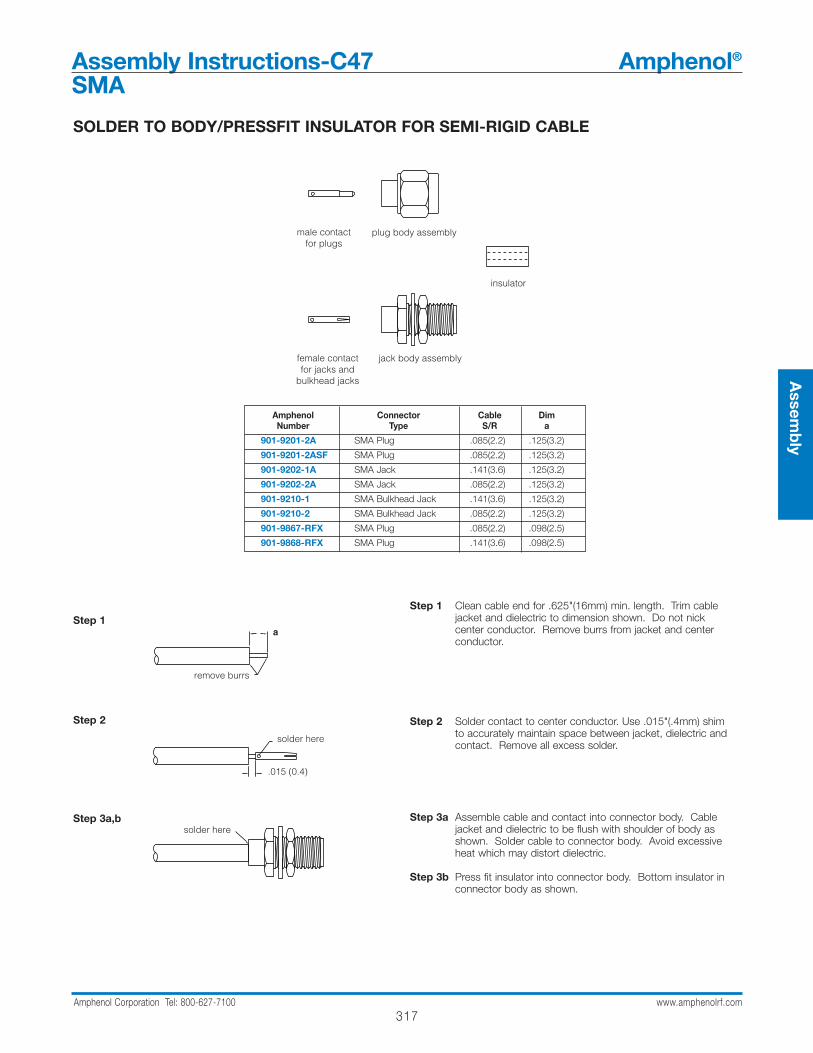
317Amphenol Corporation Tel: 800-627-7100 www.amphenolrf.com
Assem
bly
Assembly Instructions-C47 Amphenol®
SMA
Step 1
Step 2
Step 3a,b
Step 1 Clean cable end for .625"(16mm) min. length. Trim cable jacket and dielectric to dimension shown. Do not nick center conductor. Remove burrs from jacket and center conductor.
Step 2 Solder contact to center conductor. Use .015"(.4mm) shim to accurately maintain space between jacket, dielectric and contact. Remove all excess solder.
Step 3a Assemble cable and contact into connector body. Cable jacket and dielectric to be flush with shoulder of body as shown. Solder cable to connector body. Avoid excessive heat which may distort dielectric.
Step 3b Press fit insulator into connector body. Bottom insulator in connector body as shown.
Amphenol Connector Cable DimNumber Type S/R a
901-9201-2A SMA Plug .085(2.2) .125(3.2)
901-9201-2ASF SMA Plug .085(2.2) .125(3.2)
901-9202-1A SMA Jack .141(3.6) .125(3.2)
901-9202-2A SMA Jack .085(2.2) .125(3.2)
901-9210-1 SMA Bulkhead Jack .141(3.6) .125(3.2)
901-9210-2 SMA Bulkhead Jack .085(2.2) .125(3.2)
901-9867-RFX SMA Plug .085(2.2) .098(2.5)
901-9868-RFX SMA Plug .141(3.6) .098(2.5)
jack body assemblyfemale contactfor jacks and
bulkhead jacks
plug body assemblymale contactfor plugs
insulator
.015 (0.4)
a
remove burrs
solder here
solder here
SOLDER TO BODY/PRESSFIT INSULATOR FOR SEMI-RIGID CABLE
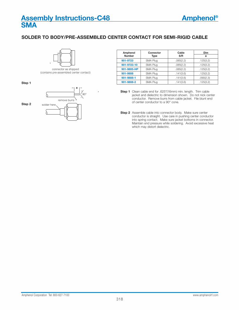
318Amphenol Corporation Tel: 800-627-7100 www.amphenolrf.com
Assembly Instructions-C48 Amphenol®
SMA
SOLDER TO BODY/PRE-ASSEMBLED CENTER CONTACT FOR SEMI-RIGID CABLE
Step 1
Step 2
Step 1 Clean cable end for .625"(16mm) min. length. Trim cable jacket and dielectric to dimension shown. Do not nick center conductor. Remove burrs from cable jacket. File blunt end of center conductor to a 90° cone.
Step 2 Assemble cable into connector body. Make sure center conductor is straight. Use care in pushing center conductor into spring contact. Make sure jacket bottoms in connector. Maintain end pressure while soldering. Avoid excessive heat which may distort dielectric.
Amphenol Connector Cable DimNumber Type S/R a
901-9723 SMA Plug .085(2.2) .125(3.2)
901-9723-10 SMA Plug .085(2.2) .125(3.2)
901-9805-HP SMA Plug .085(2.2) .125(3.2)
901-9808 SMA Plug .141(3.6) .125(3.2)
901-9808-1 SMA Plug .141(3.6) .090(2.3)
901-9808-2 SMA Plug .141(3.6) .125(3.2)
connector as shipped(contains pre-assembled center contact)
90°
a
remove burrs
solder here
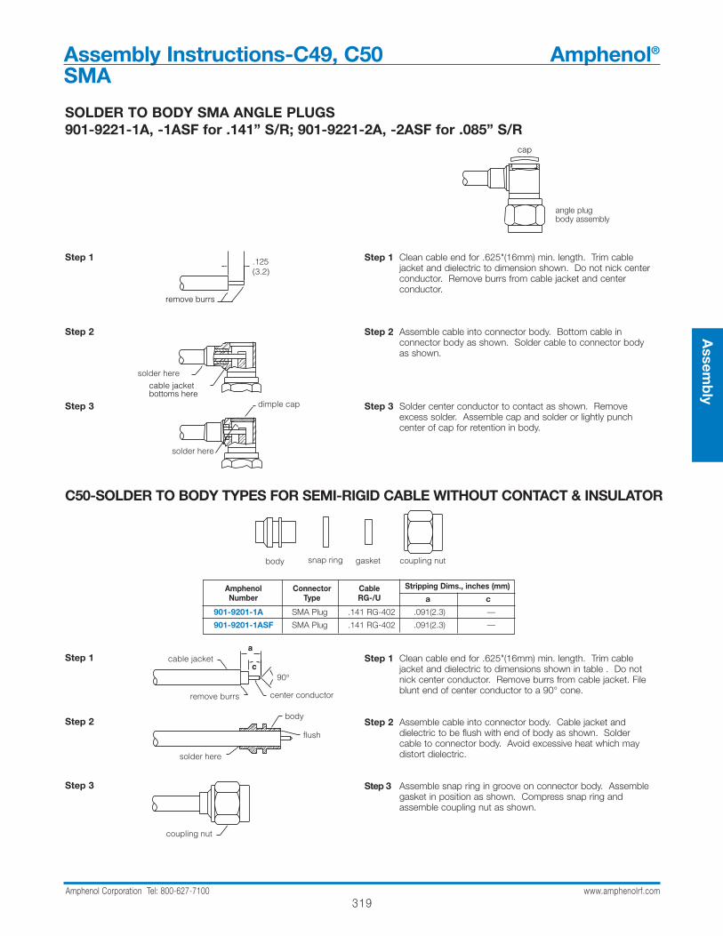
319Amphenol Corporation Tel: 800-627-7100 www.amphenolrf.com
Assem
bly
Step 1
Step 2
Step 3
Step 1 Clean cable end for .625"(16mm) min. length. Trim cable jacket and dielectric to dimension shown. Do not nick center conductor. Remove burrs from cable jacket and center conductor.
Step 2 Assemble cable into connector body. Bottom cable in connector body as shown. Solder cable to connector body as shown.
Step 3 Solder center conductor to contact as shown. Remove excess solder. Assemble cap and solder or lightly punch center of cap for retention in body.
angle plugbody assembly
cap
.125(3.2)
solder here
dimple cap
cable jacketbottoms here
solder here
remove burrs
C50-SOLDER TO BODY TYPES FOR SEMI-RIGID CABLE WITHOUT CONTACT & INSULATOR
Step 1
Step 2
Step 3
Step 1 Clean cable end for .625"(16mm) min. length. Trim cable jacket and dielectric to dimensions shown in table . Do not nick center conductor. Remove burrs from cable jacket. File blunt end of center conductor to a 90° cone.
Step 2 Assemble cable into connector body. Cable jacket and dielectric to be flush with end of body as shown. Solder cable to connector body. Avoid excessive heat which may distort dielectric.
Step 3 Assemble snap ring in groove on connector body. Assemble gasket in position as shown. Compress snap ring and assemble coupling nut as shown.
Amphenol Connector Cable Stripping Dims., inches (mm)Number Type RG-/U a c
901-9201-1A SMA Plug .141 RG-402 .091(2.3) —
901-9201-1ASF SMA Plug .141 RG-402 .091(2.3) —
coupling nutgasketsnap ringbody
90°c
a
remove burrs center conductor
coupling nut
solder here
cable jacket
flush
body
Assembly Instructions-C49, C50 Amphenol®
SMA
SOLDER TO BODY SMA ANGLE PLUGS901-9221-1A, -1ASF for .141” S/R; 901-9221-2A, -2ASF for .085” S/R

320Amphenol Corporation Tel: 800-627-7100 www.amphenolrf.com
Assembly Instructions-C51 Amphenol®
SMA
SOLDER TO COLLET METHOD FOR SEMI-RIGID CABLE SMA Plug 901-509 for .141S/R
rear C- adjustment collet contact connector assemblylock ring nut body with front locknutnut
Step 1 Strip cable jacket to dimensions shown. To avoid cuttinginto dielectric, score cable jacket and flex slightly to breakentirely through jacket. Slide rear locknut and adjustmentnut onto cable.
Step 2 Insert cable into collet body and apply axial pressure to cable to assure good metal contact at Point a. Solder cable jacket to collet body with 60/40 solder. Trim dielectric flush with tines of collet body. Do not nick cable center conductor.
Step 3 Solder contact to cable center conductor with 60/40 solderand maintain the .007 dimension shown between contact and tines. Do not permit solder on contact o.d.
Step 4 Slide adjustment nut over collet body. Install C-ring intogroove on collet body. Thread rear locknut loosely into place. Thread this assembly onto connector assembly. Make phase angle adjustment by turning adjustment nut:one revolution of nut = [0.636 x f(GHz)]° When desired phase angle is achieved, hold adjustment nut in place andturn the front locknut down against it. Then tighten rearlocknut and assembly is complete.
Step 1
Step 2
Step 3
Step 4
.562(14.2)
point a
soft solder trim dielectric flush
groove .007(0.18)
no solder on contact o.d.
front locknutadjustment nutC-ring
rear locknut
final assembly
.437(11.1) across 2 flats.437(11.1) hex
901-509
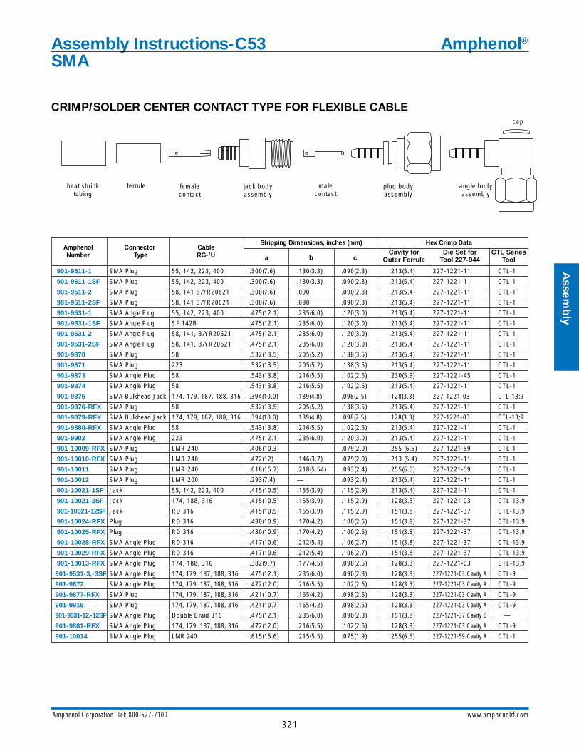
321Amphenol Corporation Tel: 800-627-7100 www.amphenolrf.com
Assem
bly
CRIMP/SOLDER CENTER CONTACT TYPE FOR FLEXIBLE CABLE
Amphenol Connector CableStripping Dimensions, inches (mm) Hex Crimp Data
Number Type RG-/U a b cCavity for Die Set for CTL Series
Outer Ferrule Tool 227-944 Tool
901-9511-1 SMA Plug 55, 142, 223, 400 .300(7.6) .130(3.3) .090(2.3) .213(5.4) 227-1221-11 CTL-1
901-9511-1SF SMA Plug 55, 142, 223, 400 .300(7.6) .130(3.3) .090(2.3) .213(5.4) 227-1221-11 CTL-1
901-9511-2 SMA Plug 58, 141 B/YR20621 .300(7.6) .090 .090(2.3) .213(5.4) 227-1221-11 CTL-1
901-9511-2SF SMA Plug 58, 141 B/YR20621 .300(7.6) .090 .090(2.3) .213(5.4) 227-1221-11 CTL-1
901-9531-1 SMA Angle Plug 55, 142, 223, 400 .475(12.1) .235(6.0) .120(3.0) .213(5.4) 227-1221-11 CTL-1
901-9531-1SF SMA Angle Plug SF 142B .475(12.1) .235(6.0) .120(3.0) .213(5.4) 227-1221-11 CTL-1
901-9531-2 SMA Angle Plug 58, 141, B/YR20621 .475(12.1) .235(6.0) .120(3.0) .213(5.4) 227-1221-11 CTL-1
901-9531-2SF SMA Angle Plug 58, 141, B/YR20621 .475(12.1) .235(6.0) .120(3.0) .213(5.4) 227-1221-11 CTL-1
901-9870 SMA Plug 58 .532(13.5) .205(5.2) .138(3.5) .213(5.4) 227-1221-11 CTL-1
901-9871 SMA Plug 223 .532(13.5) .205(5.2) .138(3.5) .213(5.4) 227-1221-11 CTL-1
901-9873 SMA Angle Plug 58 .543(13.8) .216(5.5) .102(2.6) .230(5.9) 227-1221-45 CTL-1
901-9874 SMA Angle Plug 58 .543(13.8) .216(5.5) .102(2.6) .213(5.4) 227-1221-11 CTL-1
901-9875 SMA Bulkhead Jack 174, 179, 187, 188, 316 .394(10.0) .189(4.8) .098(2.5) .128(3.3) 227-1221-03 CTL-13;9
901-9876-RFX SMA Plug 58 .532(13.5) .205(5.2) .138(3.5) .213(5.4) 227-1221-11 CTL-1
901-9879-RFX SMA Bulkhead Jack 174, 179, 187, 188, 316 .394(10.0) .189(4.8) .098(2.5) .128(3.3) 227-1221-03 CTL-13;9
901-9880-RFX SMA Angle Plug 58 .543(13.8) .216(5.5) .102(2.6) .213(5.4) 227-1221-11 CTL-1
901-9902 SMA Angle Plug 223 .475(12.1) .235(6.0) .120(3.0) .213(5.4) 227-1221-11 CTL-1
901-10009-RFX SMA Plug LMR 240 .406(10.3) — .079(2.0) .255 (6.5) 227-1221-59 CTL-1
901-10010-RFX SMA Plug LMR 240 .472(12) .146(3.7) .079(2.0) .213 (5.4) 227-1221-11 CTL-1
901-10011 SMA Plug LMR 240 .618(15.7) .218(5.54) .093(2.4) .255(6.5) 227-1221-59 CTL-1
901-10012 SMA Plug LMR 200 .293(7.4) — .093(2.4) .213(5.4) 227-1221-11 CTL-1
901-10021-1SF Jack 55, 142, 223, 400 .415(10.5) .155(3.9) .115(2.9) .213(5.4) 227-1221-11 CTL-1
901-10021-3SF Jack 174, 188, 316 .415(10.5) .155(3.9) .115(2.9) .128(3.3) 227-1221-03 CTL-13.9
901-10021-12SF Jack RD 316 .415(10.5) .155(3.9) .115(2.9) .151(3.8) 227-1221-37 CTL-13.9
901-10024-RFX Plug RD 316 .430(10.9) .170(4.2) .100(2.5) .151(3.8) 227-1221-37 CTL-13.9
901-10025-RFX Plug RD 316 .430(10.9) .170(4.2) .100(2.5) .151(3.8) 227-1221-37 CTL-13.9
901-10028-RFX SMA Angle Plug RD 316 .417(10.6) .212(5.4) .106(2.7) .151(3.8) 227-1221-37 CTL-13.9
901-10029-RFX SMA Angle Plug RD 316 .417(10.6) .212(5.4) .106(2.7) .151(3.8) 227-1221-37 CTL-13.9
901-10013-RFX SMA Angle Plug 174, 188, 316 .382(9.7) .177(4.5) .098(2.5) .128(3.3) 227-1221-03 CTL-13.9
901-9531-3,-3SF SMA Angle Plug 174, 179, 187, 188, 316 .475(12.1) .235(6.0) .090(2.3) .128(3.3) 227-1221-03 Cavity A CTL-9
901-9872 SMA Angle Plug 174, 179, 187, 188, 316 .472(12.0) .216(5.5) .102(2.6) .128(3.3) 227-1221-03 Cavity A CTL-9
901-9877-RFX SMA Plug 174, 179, 187, 188, 316 .421(10.7) .165(4.2) .098(2.5) .128(3.3) 227-1221-03 Cavity A CTL-9
901-9916 SMA Plug 174, 179, 187, 188, 316 .421(10.7) .165(4.2) .098(2.5) .128(3.3) 227-1221-03 Cavity A CTL-9
901-9531-12,-12SF SMA Angle Plug Double Braid 316 .475(12.1) .235(6.0) .090(2.3) .151(3.8) 227-1221-37 Cavity B —
901-9881-RFX SMA Angle Plug 174, 179, 187, 188, 316 .472(12.0) .216(5.5) .102(2.6) .128(3.3) 227-1221-03 Cavity A CTL-9
901-10014 SMA Angle Plug LMR 240 .615(15.6) .215(5.5) .075(1.9) .255(6.5) 227-1221-59 Cavity A CTL-1
jack body assembly
female contact
cap
plug body assembly
male contact
ferruleheat shrink tubing
angle body assembly
Assembly Instructions-C53 Amphenol®
SMA
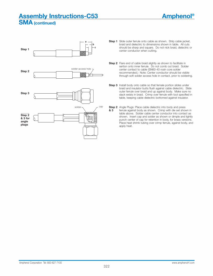
322Amphenol Corporation Tel: 800-627-7100 www.amphenolrf.com
Assembly Instructions-C53 Amphenol®
SMA (continued)
Step 1
Step 2
Step 3
Step 2& 3 for angle plugs
Step 1 Slide outer ferrule onto cable as shown. Strip cable jacket, braid and dielectric to dimensions shown in table. All cuts should be sharp and square. Do not nick braid, dielectric or center conductor when cutting.
Step 2 Flare end of cable braid slightly as shown to facilitate insertion onto inner ferrule. Do not comb out braid. Solder center contact to cable (SN60-40 rosin core solder recommended.) Note: Center conductor should be visible through soft solder access hole in contact, prior to soldering.
Step 3 Install body onto cable so that female portion slides under braid and insulator butts flush against cable dielectric. Slide outer ferrule over braid and up against body. Make sure no slack exists in braid. Crimp over ferrule with tool specified in table, keeping cable dielectric bottomed against insulator.
Step 2 Angle Plugs: Place cable dielectric into body and press & 3 ferrule against body as shown. Crimp with die set shown in
table above. Solder cable center conductor into contact asshown. Insert cap and solder as shown or dimple and lightlypunch center of cap for retention in body, for brass versions.Place heat shrink tubing over crimp ferrule, against body, andapply heat.
ab
c
solder cap
solder access hole

323Amphenol Corporation Tel: 800-627-7100 www.amphenolrf.com
Assem
bly
CRIMP-CRIMP TYPES FOR FLEXIBLE CABLE
Step 1
.
Step 2
Step 3
Step 1 Slide heat shrink tubing and outer ferrule onto cable. Strip cable jacket, braid and dielectric to dimensions shown in table above. All cuts are to be sharp and square. Do not nick braid, dielectric or center conductor when cutting. Flare end of cable braid slightly as shown to facilitate insertion of inner ferrule. Do not comb out braid.
Step 2 For crimp contact type only:Crimp center contact to cable conductor using 8-indent Tool and Positioner shown in Table above. Note: Contact must bottom against cable dielectric.*For solder type connectors: Solder contact to center conductor.
Step 3 Install inner ferrule of body assembly over cable dielectric and under braid. Place outer ferrule against body and crimp with tool 227-944 (M22520/5-01) and die set shown in table above. Place heat shrink tubing over crimp ferrule, against body, and apply heat.
Amphenol Connector CableStripping Dimensions, inches (mm) Contact Data Outer Ferrule Data CTL
Number Type RG-/U a b cPositioner for Positioner for Hex Cav. for Die Set for SeriesTool 227-1454 M22520/1-01 Outer ferrule Tool 227-944 Tool
901-101-15* SMA Plug 142B, 400 .531(13.5) .250(3.2) .141(3.6) — /1-15 .213(5.4) 227-1221-11 Cav. A CTL-1
901-9511-1SFC SMA Plug 55, 58, 141, .300(7.6) — .090(2.3) 227-1451-1 — .213(5.4) 227-1221-11 Cav. A CTL-1142, 223, 400
901-9511-3* SMA Plug 174, 179B, .470(11.9) .170(4.3) .120(3.0) 227-1451-1 — .128(3.3) 227-1221-03 CTL-13;9
901-9511-3SF* SMA Plug 187A, 316 .470(11.9) .170(4.3) .120(3.0) 227-1451-1 — .128(3.3) 227-1221-03 CTL-13;9
901-9511-3SFC SMA Plug 174, 179, 187 .470(11.9) .170(4.3) .120(3.0) 227-1451-1 — .128(3.3) 227-1221-03 CTL-13;9
188, 316
901-9511-12SF* SMA Plug Dbl. Br. 316 .470(11.9) .170(4.3) .120(3.0) 227-1451-1 — .151(3.8) 227-1221-37 Cav. B CTL-13;9
901-9511-12SFC SMA Plug Dbl. Br. 316 .470(11.9) .170(4.3) .120(3.0) 227-1451-1 — .151(3.8) 227-1221-37 Cav. B CTL-13;9
body assemblycenter contactferruleheat shrinktubing
a
c
contact bottoms here
contact crimp area
outer ferrule butts here
b
Assembly Instructions-C55 Amphenol®
SMA

Step 1 Slide heat shrink tubing and outer ferrule onto cable. Strip cable jacket, braid and dielectric to dimensions shown in table above. All cuts are to be sharp and square. Do not nick braid, dielectric or center conductor when cutting. Tin center conductor. Avoid excessive heat to prevent swelling of cable dielectric. Flare end of cable braid slightly as shown to facilitate insertion of inner ferrule. Do not comb out braid.
Step 2 Slide clamp nut over inner ferrule, and slide inner ferrule under braid until cable dielectric is flush with front of inner ferrule. Slide outer ferrule in place and crimp with die set shown in table above.
Step 3 Place insulator washer on cable center conductor and bottom against inner ferrule body as shown. Contact must butt firmly against insulator washer while soldering.
Step 4 Screw ferrule-contact assembly into body and tighten to 20-25 lbf.-in. torque. Slide heat shrink tubing over ferrule, up against clamp nut and shrink by applying heat.
insulator washer
ab
c
Step 2
Step 1
Step 3
Step 4
324Amphenol Corporation Tel: 800-627-7100 www.amphenolrf.com
BRAID CRIMP-SOLDER CENTER CONTACT TYPES FOR FLEXIBLE CABLE
Amphenol Connector Cable RG-/U Strip Dimensions, inches (mm) Hex Cavity for Die Set forNumber Type a b c Outer Ferrule Tool 227-944
901-9601-1SF SMA Plug 55,58,141,142,223,400 .620(15.7) .350(8.9) .120(3.0) .213(5.4) 227-1221-11 Cavity A
901-9601-3 SMA Plug 174,179,187,188,316 .620(15.7) .350(8.9) .120(3.0) .128(3.3) 227-1221-03 Cavity A
901-9601-3SF SMA Plug 174,179,187,188,316 .620(15.7) .350(8.9) .120(3.0) .128(3.3) 227-1221-03 Cavity A
901-9602-1, -1SF SMA Jack 55,58,141,142,223,400 .610(15.5) .340(8.6) .110(2.8) .213(5.4) 227-1221-11 Cavity A
901-9602-3, -3SF SMA Jack 174,179,187,188,316 .610(15.5) .340(8.6) .110(2.8) .128(3.3) 227-1221-03 Cavity A
901-9602-12SF SMA Jack Double Braid 316 .610(15.5) .340(8.6) .110(2.8) .128(3.3) 227-1221-03 Cavity A
901-9610-1SF SMA Bulkhead Jack 55,58,141,142,223,400 .610(15.5) .340(8.6) .110(2.8) .213(5.4) 227-1221-11 Cavity A
901-9610-3, -3SF SMA Bulkhead Jack 174,179,187,188,316 .610(15.5) .340(8.6) .110(2.8) .128(3.3) 227-1221-03 Cavity A
901-9610-12SF SMA Bulkhead Jack Double Braid 316 .610(15.5) .340(8.6) .110(2.8) .151(3.8) 227-1221-37 Cavity B
901-10015 SMA Bulkhead Jack LMR 240 4.93(12.5) — .043(2.4) .255(6.5) 227-1221-59 Cavity A
shrinktubing
outerferrule
clamp nut &inner ferrule
insulatorwasher
male contact
plug body femalecontact
bulkhead jack or jack body
Assembly Instructions-C56 Amphenol®
SMA
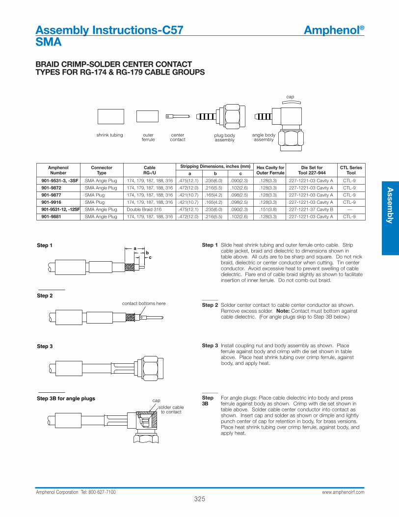
325Amphenol Corporation Tel: 800-627-7100 www.amphenolrf.com
Assem
bly
BRAID CRIMP-SOLDER CENTER CONTACT TYPES FOR RG-174 & RG-179 CABLE GROUPS
Step 1 Slide heat shrink tubing and outer ferrule onto cable. Strip cable jacket, braid and dielectric to dimensions shown in table above. All cuts are to be sharp and square. Do not nick braid, dielectric or center conductor when cutting. Tin center conductor. Avoid excessive heat to prevent swelling of cable dielectric. Flare end of cable braid slightly as shown to facilitate insertion of inner ferrule. Do not comb out braid.
Step 2 Solder center contact to cable center conductor as shown. Remove excess solder. Note: Contact must bottom against cable dielectric. (For angle plugs skip to Step 3B below.)
Step 3 Install coupling nut and body assembly as shown. Place ferrule against body and crimp with die set shown in table above. Place heat shrink tubing over crimp ferrule, against body, and apply heat.
Step For angle plugs: Place cable dielectric into body and press 3B ferrule against body as shown. Crimp with die set shown in
table above. Solder cable center conductor into contact asshown. Insert cap and solder as shown or dimple and lightlypunch center of cap for retention in body, for brass versions.Place heat shrink tubing over crimp ferrule, against body, andapply heat.
Amphenol Connector Cable Stripping Dimensions, inches (mm) Hex Cavity for Die Set for CTL SeriesNumber Type RG-/U a b c Outer Ferrule Tool 227-944 Tool
901-9531-3, -3SF SMA Angle Plug 174, 179, 187, 188, 316 .475(12.1) .235(6.0) .090(2.3) .128(3.3) 227-1221-03 Cavity A CTL-9
901-9872 SMA Angle Plug 174, 179, 187, 188, 316 .472(12.0) .216(5.5) .102(2.6) .128(3.3) 227-1221-03 Cavity A CTL-9
901-9877 SMA Plug 174, 179, 187, 188, 316 .421(10.7) .165(4.2) .098(2.5) .128(3.3) 227-1221-03 Cavity A CTL-9
901-9916 SMA Plug 174, 179, 187, 188, 316 .421(10.7) .165(4.2) .098(2.5) .128(3.3) 227-1221-03 Cavity A CTL-9
901-9531-12, -12SF SMA Angle Plug Double Braid 316 .475(12.1) .235(6.0) .090(2.3) .151(3.8) 227-1221-37 Cavity B —
901-9881 SMA Angle Plug 174, 179, 187, 188, 316 .472(12.0) .216(5.5) .102(2.6) .128(3.3) 227-1221-03 Cavity A CTL-9
shrink tubing centercontact
outerferrule
cap
plug bodyassembly
angle bodyassembly
contact bottoms here
Step 3
Step 3B for angle plugs
cb
aStep 1
Step 2
cap
solder cableto contact
Assembly Instructions-C57 Amphenol®
SMA
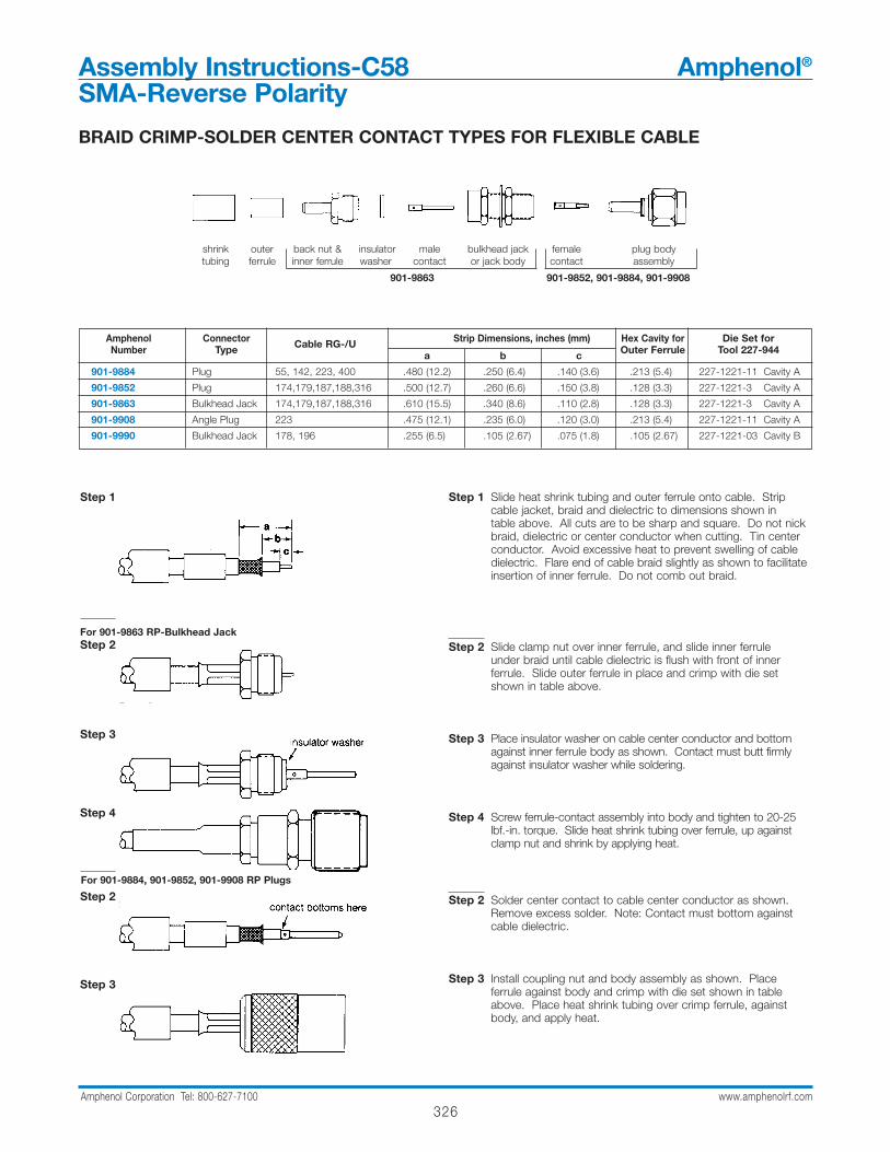
326Amphenol Corporation Tel: 800-627-7100 www.amphenolrf.com
BRAID CRIMP-SOLDER CENTER CONTACT TYPES FOR FLEXIBLE CABLE
Step 1
For 901-9863 RP-Bulkhead JackStep 2
Step 3
Step 4
For 901-9852 RP-PlugStep 2
Step 3
Step 1 Slide heat shrink tubing and outer ferrule onto cable. Strip cable jacket, braid and dielectric to dimensions shown in table above. All cuts are to be sharp and square. Do not nick braid, dielectric or center conductor when cutting. Tin center conductor. Avoid excessive heat to prevent swelling of cable dielectric. Flare end of cable braid slightly as shown to facilitateinsertion of inner ferrule. Do not comb out braid.
Step 2 Slide clamp nut over inner ferrule, and slide inner ferrule under braid until cable dielectric is flush with front of inner ferrule. Slide outer ferrule in place and crimp with die set shown in table above.
Step 3 Place insulator washer on cable center conductor and bottom against inner ferrule body as shown. Contact must butt firmly against insulator washer while soldering.
Step 4 Screw ferrule-contact assembly into body and tighten to 20-25 lbf.-in. torque. Slide heat shrink tubing over ferrule, up against clamp nut and shrink by applying heat.
Step 2 Solder center contact to cable center conductor as shown. Remove excess solder. Note: Contact must bottom against cable dielectric.
Step 3 Install coupling nut and body assembly as shown. Place ferrule against body and crimp with die set shown in table above. Place heat shrink tubing over crimp ferrule, against body, and apply heat.
Amphenol Connector Cable RG-/U Strip Dimensions, inches (mm) Hex Cavity for Die Set forNumber Type a b c Outer Ferrule Tool 227-944
901-9884 Plug 55, 142, 223, 400 .480 (12.2) .250 (6.4) .140 (3.6) .213 (5.4) 227-1221-11 Cavity A
901-9852 Plug 174,179,187,188,316 .500 (12.7) .260 (6.6) .150 (3.8) .128 (3.3) 227-1221-3 Cavity A
901-9863 Bulkhead Jack 174,179,187,188,316 .610 (15.5) .340 (8.6) .110 (2.8) .128 (3.3) 227-1221-3 Cavity A
901-9908 Angle Plug 223 .475 (12.1) .235 (6.0) .120 (3.0) .213 (5.4) 227-1221-11 Cavity A
901-9990 Bulkhead Jack 178, 196 .255 (6.5) .105 (2.67) .075 (1.8) .105 (2.67) 227-1221-03 Cavity B
shrink outer back nut & insulator male bulkhead jack female plug bodytubing ferrule inner ferrule washer contact or jack body contact assembly
901-9863 901-9852, 901-9884, 901-9908
For 901-9884, 901-9852, 901-9908 RP Plugs
Assembly Instructions-C58 Amphenol®
SMA-Reverse Polarity
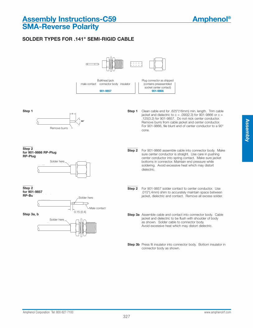
327Amphenol Corporation Tel: 800-627-7100 www.amphenolrf.com
Assem
bly
Assembly Instructions-C59 Amphenol®
SMA-Reverse Polarity
SOLDER TYPES FOR .141" SEMI-RIGID CABLE
Step 1
Step 2for 901-9866 RP-PlugRP-Plug
Step 2for 901-9857 RP-Bulkhead Jack
Step 3a, b
Step 1 Clean cable end for .625"(16mm) min. length. Trim cable jacket and dielectric to c = .090(2.3) for 901-9866 or c = .125(3.2) for 901-9857. Do not nick center conductor. Remove burrs from cable jacket and center conductor. For 901-9866, file blunt end of center conductor to a 90°cone.
Step 2 For 901-9866 assemble cable into connector body. Make sure center conductor is straight. Use care in pushing center conductor into spring contact. Make sure jacket bottoms in connector. Maintain end pressure while soldering. Avoid excessive heat which may distort dielectric.
Step 2 For 901-9857 solder contact to center conductor. Use .015"(.4mm) shim to accurately maintain space between jacket, dielectric and contact. Remove all excess solder.
Step 3a Assemble cable and contact into connector body. Cable jacket and dielectric to be flush with shoulder of body as shown. Solder cable to connector body. Avoid excessive heat which may distort dielectric.
Step 3b Press fit insulator into connector body. Bottom insulator in connector body as shown.
Bulkhead jack Plug connector as shippedmale contact connector body insulator (contains preassembled
socket center contact)901-9857 901-9866
90
A
REMOVE BURRS
STEP 1
SOLDER HERESTEP 3 A & B
SOLDER HERE
RP-PLUGFOR 901-9866
STEP 2
STEP 2
.015 (0.4)
RP-BULKHD JACKFOR 901-9857
MALE CONTACT
SOLDER HERE
STEP 2
c
Solder here
Solder here
Solder here
Remove burrs
Male contact
90°
0.15 (0.4)
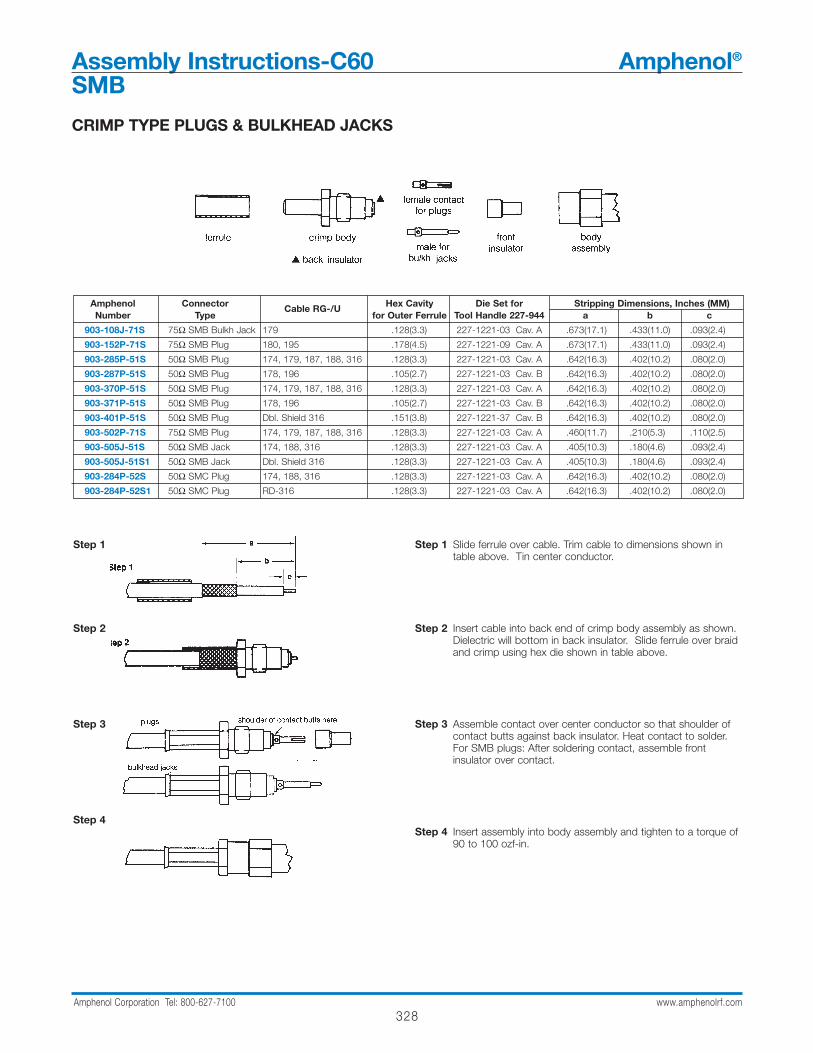
328Amphenol Corporation Tel: 800-627-7100 www.amphenolrf.com
CRIMP TYPE PLUGS & BULKHEAD JACKS
Amphenol Connector Cable RG-/U Hex Cavity Die Set for Stripping Dimensions, Inches (MM)Number Type for Outer Ferrule Tool Handle 227-944 a b c
903-108J-71S 75Ω SMB Bulkh Jack 179 .128(3.3) 227-1221-03 Cav. A .673(17.1) .433(11.0) .093(2.4)
903-152P-71S 75Ω SMB Plug 180, 195 .178(4.5) 227-1221-09 Cav. A .673(17.1) .433(11.0) .093(2.4)
903-285P-51S 50Ω SMB Plug 174, 179, 187, 188, 316 .128(3.3) 227-1221-03 Cav. A .642(16.3) .402(10.2) .080(2.0)
903-287P-51S 50Ω SMB Plug 178, 196 .105(2.7) 227-1221-03 Cav. B .642(16.3) .402(10.2) .080(2.0)
903-370P-51S 50Ω SMB Plug 174, 179, 187, 188, 316 .128(3.3) 227-1221-03 Cav. A .642(16.3) .402(10.2) .080(2.0)
903-371P-51S 50Ω SMB Plug 178, 196 .105(2.7) 227-1221-03 Cav. B .642(16.3) .402(10.2) .080(2.0)
903-401P-51S 50Ω SMB Plug Dbl. Shield 316 .151(3.8) 227-1221-37 Cav. B .642(16.3) .402(10.2) .080(2.0)
903-502P-71S 75Ω SMB Plug 174, 179, 187, 188, 316 .128(3.3) 227-1221-03 Cav. A .460(11.7) .210(5.3) .110(2.5)
903-505J-51S 50Ω SMB Jack 174, 188, 316 .128(3.3) 227-1221-03 Cav. A .405(10.3) .180(4.6) .093(2.4)
903-505J-51S1 50Ω SMB Jack Dbl. Shield 316 .128(3.3) 227-1221-03 Cav. A .405(10.3) .180(4.6) .093(2.4)
903-284P-52S 50Ω SMC Plug 174, 188, 316 .128(3.3) 227-1221-03 Cav. A .642(16.3) .402(10.2) .080(2.0)
903-284P-52S1 50Ω SMC Plug RD-316 .128(3.3) 227-1221-03 Cav. A .642(16.3) .402(10.2) .080(2.0)
Step 1 Slide ferrule over cable. Trim cable to dimensions shown intable above. Tin center conductor.
Step 2 Insert cable into back end of crimp body assembly as shown.Dielectric will bottom in back insulator. Slide ferrule over braidand crimp using hex die shown in table above.
Step 3 Assemble contact over center conductor so that shoulder ofcontact butts against back insulator. Heat contact to solder.For SMB plugs: After soldering contact, assemble frontinsulator over contact.
Step 4 Insert assembly into body assembly and tighten to a torque of90 to 100 ozf-in.
Step 1
Step 2
Step 3
Step 4
Assembly Instructions-C60 Amphenol®
SMB

329Amphenol Corporation Tel: 800-627-7100 www.amphenolrf.com
Assem
bly
CRIMP TYPE ANGLE PLUGS & ANGLE BULKHEAD JACKS
Amphenol Connector Cable RG-/U Hex Cavity for Die Set for Stripping Dimensions, Inches (mm)Number Type Outer Ferrule Tool Handle 227-944 a b c
903-517P-71A 75Ω SMC Angle Plug Belden 735A .178(4.5) 227-1221-09 Cav. A .440(11.2) .180(4.57) .090(2.28)
903-289P-51A 50Ω SMB Angle Plug 174, 179, 187, 188, 316 .128(3.3) 227-1221-03 Cav. A .390(9.9) .150(3.8) .050(1.3)
903-289P-51A2 50Ω SMB Angle Plug 174, 179, 187, 188, 316 .128(3.3) 227-1221-03 Cav. A .390(9.9) .150(3.8) .050(1.3)
903-291P-51A 50Ω SMB Angle Plug 178, 196 .105(2.7) 227-1221-03 Cav. B .390(9.9) .150(3.8) .050(1.3)
903-291P-51A1 50Ω SMB Angle Plug 178, 196 .105(2.7) 227-1221-03 Cav. B .390(9.9) .150(3.8) .050(1.3)
903-367P-51A 50Ω SMB Angle Plug 174, 179, 187, 188, 316 .128(3.3) 227-1221-03 Cav. A .390(9.9) .150(3.8) .050(1.3)
903-367P-51A1 50Ω SMB Angle Plug 174, 179, 187, 188, 316 .128(3.3) 227-1221-03 Cav. A .390(9.9) .150(3.8) .050(1.3)
903-367P-51A2 50Ω SMB Angle Plug 174, 179, 187, 188, 316 .128(3.3) 227-1221-03 Cav. A .390(9.9) .150(3.8) .050(1.3)
903-368P-51A 50Ω SMB Angle Plug 178, 196 .105(2.7) 227-1221-03 Cav. B .390(9.9) .150(3.8) .050(1.3)
903-368P-51A1 50Ω SMB Angle Plug 178, 196 .105(2.7) 227-1221-03 Cav. B .390(9.9) .150(3.8) .050(1.3)
903-369P-51A 50Ω SMB Angle Plug Dbl. Braid RG-316 .151(3.8) 227-1221-37 Cav. B .390(9.9) .150(3.8) .050(1.3)
903-369P-51A2 50Ω SMB Angle Plug Dbl. Braid RG-316 .151(3.8) 227-1221-37 Cav. B .390(9.9) .150(3.8) .050(1.3)
903-422J-51A 50Ω SMB Ang.Blkh Jack 174, 179, 187, 188, 316 .128(3.3) 227-1221-03 Cav. A .390(9.9) .150(3.8) .050(1.3)
903-429P-51A 50Ω SMB Low Prof. Angl Plg 174, 179, 187, 188, 316 .128(3.3) 227-1221-03 Cav. A .400(10.2) .200(5.1) .050(1.3)
903-495P-71A 75Ω SMB Angle Plug Belden 9248 .324(8.2) 227-1221-32 Cav. A .500(12.7) .250(6.4) .250(6.4)
903-535P-71A 75Ω SMB Angle Plug 179 .178(4.5) 227-1221-09 Cav. A .440(11.2) .180(4.57) .090(2.28)
903-288P-52A 75Ω SMB Angle Plug 174, 188, 316 .128(3.3) 227-1221-03 Cav. A .390(9.9) .150(3.2) .050(1.3)
903-362P-52A1 75Ω SMB Angle Plug RD-316 .151(3.8) 227-1221-37 Cav. B .390(9.9) .150(3.2) .050(1.3)
Step 1 Slide ferrule over cable. Trim cable to dimensions shown in table above. Tin center conductor. for P/N 903-429P-51A only, make 2 slits in jacket .062"(1.6mm) long, 180° apart.
Step 2 Insert cable into back end of crimp body assembly as shown. Center conductor will enter slot in contact. Slide ferrule over braid and crimp using hex die shown in table above.
Step 3 Solder center conductor into contact.
Step 4 Insert cap into body and dimple or lightly punch center of cap for retention in body.
Step 1
Step 2
Step 3
Step 4
ferrule crimp body assembly cap
Assembly Instructions-C61 Amphenol®
SMB
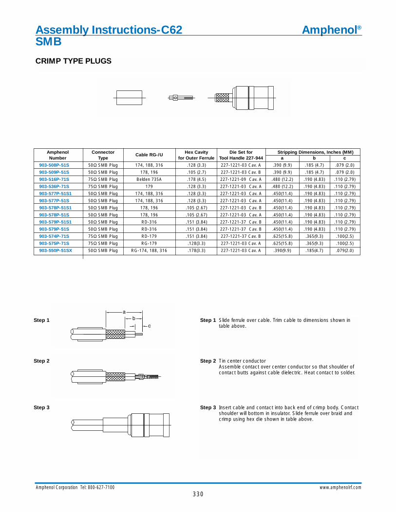
330Amphenol Corporation Tel: 800-627-7100 www.amphenolrf.com
Assembly Instructions-C62 Amphenol®
SMB
CRIMP TYPE PLUGS
Amphenol Connector Cable RG-/U Hex Cavity Die Set for Stripping Dimensions, Inches (MM)Number Type for Outer Ferrule Tool Handle 227-944 a b c
903-508P-51S 50Ω SMB Plug 174, 188, 316 .128 (3.3) 227-1221-03 Cav. A .390 (9.9) .185 (4.7) .079 (2.0)
903-509P-51S 50Ω SMB Plug 178, 196 .105 (2.7) 227-1221-03 Cav. B .390 (9.9) .185 (4.7) .079 (2.0)
903-516P-71S 75Ω SMB Plug Belden 735A .178 (4.5) 227-1221-09 Cav. A .480 (12.2) .190 (4.83) .110 (2.79)
903-536P-71S 75Ω SMB Plug 179 .128 (3.3) 227-1221-03 Cav. A .480 (12.2) .190 (4.83) .110 (2.79)
903-577P-51S1 50Ω SMB Plug 174, 188, 316 .128 (3.3) 227-1221-03 Cav. A .450(11.4) .190 (4.83) .110 (2.79)
903-577P-51S 50Ω SMB Plug 174, 188, 316 .128 (3.3) 227-1221-03 Cav. A .450(11.4) .190 (4.83) .110 (2.79)
903-578P-51S1 50Ω SMB Plug 178, 196 .105 (2.67) 227-1221-03 Cav. B .450(11.4) .190 (4.83) .110 (2.79)
903-578P-51S 50Ω SMB Plug 178, 196 .105 (2.67) 227-1221-03 Cav. A .450(11.4) .190 (4.83) .110 (2.79)
903-579P-51S1 50Ω SMB Plug RD-316 .151 (3.84) 227-1221-37 Cav. B .450(11.4) .190 (4.83) .110 (2.79)
903-579P-51S 50Ω SMB Plug RD-316 .151 (3.84) 227-1221-37 Cav. B .450(11.4) .190 (4.83) .110 (2.79)
903-574P-71S 75Ω SMB Plug RD-179 .151 (3.84) 227-1221-37 Cav. B .625(15.8) .365(9.3) .100(2.5)
903-575P-71S 75Ω SMB Plug RG-179 .128(3.3) 227-1221-03 Cav. A .625(15.8) .365(9.3) .100(2.5)
903-550P-51SX 50Ω SMB Plug RG-174, 188, 316 .178(3.3) 227-1221-03 Cav. A .390(9.9) .185(4.7) .079(2.0)
Step 1 Slide ferrule over cable. Trim cable to dimensions shown intable above.
Step 2 Tin center conductorAssemble contact over center conductor so that shoulder ofcontact butts against cable dielectric. Heat contact to solder.
Step 3 Insert cable and contact into back end of crimp body. Contactshoulder will bottom in insulator. Slide ferrule over braid andcrimp using hex die shown in table above.
Step 1
Step 2
Step 3
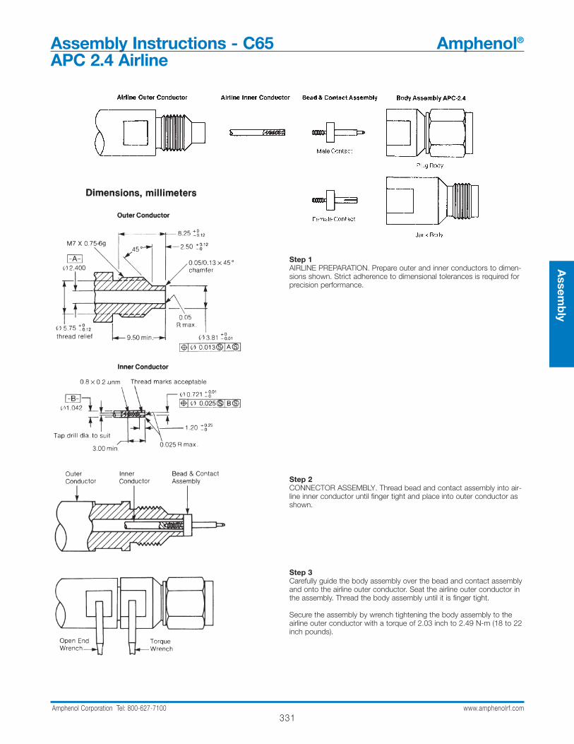
331Amphenol Corporation Tel: 800-627-7100 www.amphenolrf.com
Assem
bly
Assembly Instructions - C65 Amphenol®
APC 2.4 Airline
Step 1AIRLINE PREPARATION. Prepare outer and inner conductors to dimen-sions shown. Strict adherence to dimensional tolerances is required forprecision performance.
Step 2CONNECTOR ASSEMBLY. Thread bead and contact assembly into air-line inner conductor until finger tight and place into outer conductor asshown.
Step 3Carefully guide the body assembly over the bead and contact assemblyand onto the airline outer conductor. Seat the airline outer conductor inthe assembly. Thread the body assembly until it is finger tight.
Secure the assembly by wrench tightening the body assembly to theairline outer conductor with a torque of 2.03 inch to 2.49 N-m (18 to 22inch pounds).
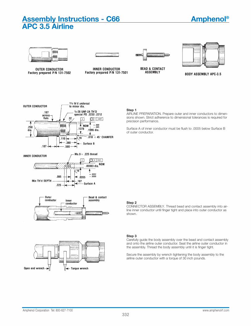
Assembly Instructions - C66 Amphenol®
APC 3.5 Airline
332Amphenol Corporation Tel: 800-627-7100 www.amphenolrf.com
Step 1AIRLINE PREPARATION. Prepare outer and inner conductors to dimen-sions shown. Strict adherence to dimensional tolerances is required forprecision performance.
Surface A of inner conductor must be flush to .0005 below Surface Bof outer conductor.
Step 2CONNECTOR ASSEMBLY. Thread bead and contact assembly into air-line inner conductor until finger tight and place into outer conductor asshown.
Step 3Carefully guide the body assembly over the bead and contact assemblyand onto the airline outer conductor. Seat the airline outer conductor inthe assembly. Thread the body assembly until it is finger tight.
Secure the assembly by wrench tightening the body assembly to theairline outer conductor with a torque of 30 inch pounds.
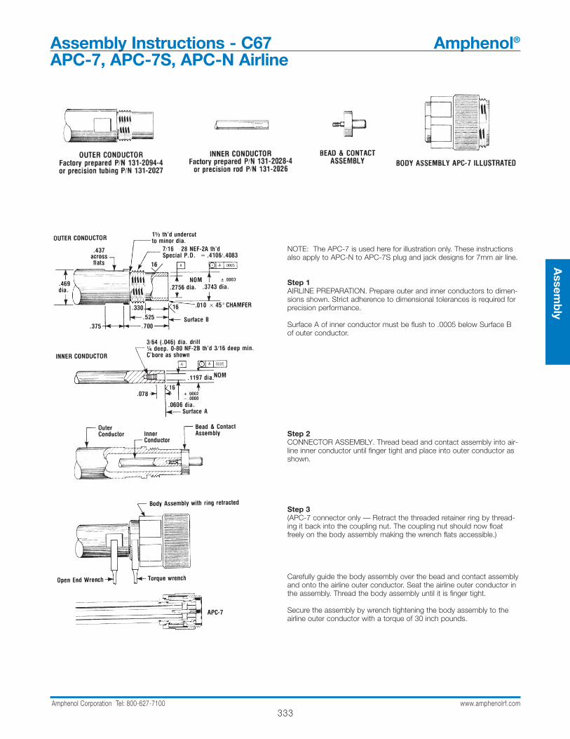
Assembly Instructions - C67 Amphenol®
APC-7, APC-7S, APC-N Airline
333Amphenol Corporation Tel: 800-627-7100 www.amphenolrf.com
Assem
bly
NOTE: The APC-7 is used here for illustration only. These instructionsalso apply to APC-N to APC-7S plug and jack designs for 7mm air line.
Step 1AIRLINE PREPARATION. Prepare outer and inner conductors to dimen-sions shown. Strict adherence to dimensional tolerances is required forprecision performance.
Surface A of inner conductor must be flush to .0005 below Surface Bof outer conductor.
Step 2CONNECTOR ASSEMBLY. Thread bead and contact assembly into air-line inner conductor until finger tight and place into outer conductor asshown.
Step 3(APC-7 connector only — Retract the threaded retainer ring by thread-ing it back into the coupling nut. The coupling nut should now floatfreely on the body assembly making the wrench flats accessible.)
Carefully guide the body assembly over the bead and contact assemblyand onto the airline outer conductor. Seat the airline outer conductor inthe assembly. Thread the body assembly until it is finger tight.
Secure the assembly by wrench tightening the body assembly to theairline outer conductor with a torque of 30 inch pounds.
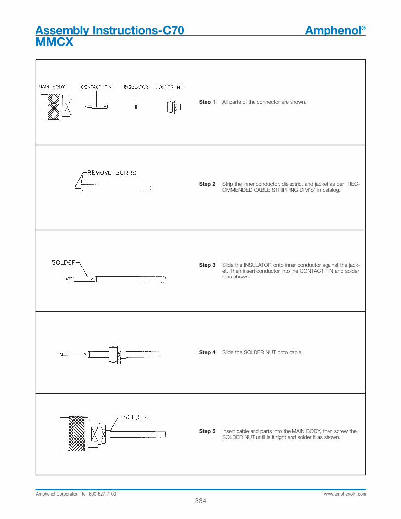
334Amphenol Corporation Tel: 800-627-7100 www.amphenolrf.com
Step 1 All parts of the connector are shown.
Step 2 Strip the inner conductor, dielectric, and jacket as per “REC-OMMENDED CABLE STRIPPING DIM’S” in catalog.
Step 3 Slide the INSULATOR onto inner conductor against the jack-et. Then insert conductor into the CONTACT PIN and solderit as shown.
Step 4 Slide the SOLDER NUT onto cable.
Step 5 Insert cable and parts into the MAIN BODY, then screw theSOLDER NUT until is it tight and solder it as shown.
Assembly Instructions-C70 Amphenol®
MMCX
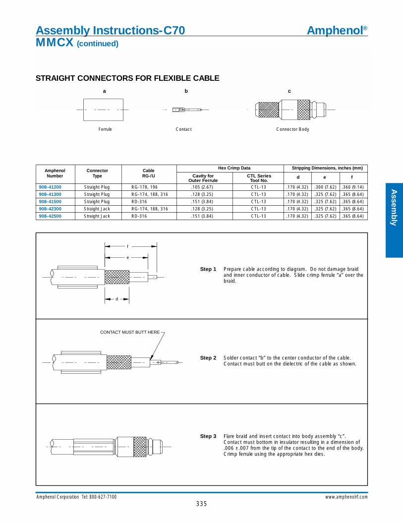
335Amphenol Corporation Tel: 800-627-7100 www.amphenolrf.com
Assem
bly
STRAIGHT CONNECTORS FOR FLEXIBLE CABLE
Step 1 Prepare cable according to diagram. Do not damage braidand inner conductor of cable. Slide crimp ferrule “a” over thebraid.
Step 2 Solder contact “b” to the center conductor of the cable.Contact must butt on the dielectric of the cable as shown.
Step 3 Flare braid and insert contact into body assembly “c”.Contact must bottom in insulator resulting in a dimension of.006 ±.007 from the tip of the contact to the end of the body.Crimp ferrule using the appropriate hex dies.
Ferrule Contact Connector Body
CONTACT MUST BUTT HERE
f
e
d
a b c
Amphenol Connector Cable Hex Crimp Data Stripping Dimensions, inches (mm)
Number Type RG-/U Cavity for CTL SeriesOuter Ferrule Tool No.
d e f
908-41200 Straight Plug RG-178, 196 .105 (2.67) CTL-13 .170 (4.32) .300 (7.62) .360 (9.14)
908-41300 Straight Plug RG-174, 188, 316 .128 (3.25) CTL-13 .170 (4.32) .325 (7.62) .365 (8.64)
908-41500 Straight Plug RD-316 .151 (3.84) CTL-13 .170 (4.32) .325 (7.62) .365 (8.64)
908-42300 Straight Jack RG-174, 188, 316 .128 (3.25) CTL-13 .170 (4.32) .325 (7.62) .365 (8.64)
908-42500 Straight Jack RD-316 .151 (3.84) CTL-13 .170 (4.32) .325 (7.62) .365 (8.64)
Assembly Instructions-C70 Amphenol®
MMCX (continued)

336Amphenol Corporation Tel: 800-627-7100 www.amphenolrf.com
STRAIGHT CONNECTORS FOR SEMI-RIGID CABLE
Step 1 Prepare cable according to diagram. Remove burrs fromouter/inner conductors of cable.
Step 2 Solder center contact “a” to inner conductor of cable usingSn60 solder. Contact must butt on dielectric of cable asshown.
Step 3 Insert contact into body assembly “b” as shown. Holdingbody and cable firmly, apply heat as shown and feed solder(Sn-60) as indicated. Allow to cool. The dimension from thecontact tip to the end of the body should be .006 ±.007.
Contact Connector Body
APPLY HEAT
FEED SOLDER HERE
CONTACT MUST BUTT HERE
c
d
a b
Amphenol Connector Cable Stripping Dimensions, inches (mm)
Number Type RG-/U c d
908-41400 Straight Plug .086 Semi-Rigid .180 (4.57) .140 (3.56)
908-41600 Straight Plug .047 Semi-Rigid .200 (5.08) .140 (3.56)
Assembly Instructions-C71 Amphenol®
MMCX
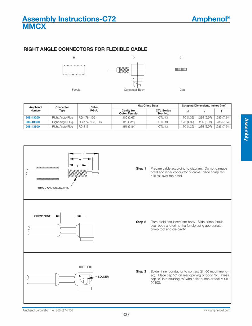
337Amphenol Corporation Tel: 800-627-7100 www.amphenolrf.com
RIGHT ANGLE CONNECTORS FOR FLEXIBLE CABLE
Step 1 Prepare cable according to diagram. Do not damagebraid and inner conductor of cable. Slide crimp fer-rule “a” over the braid.
Step 2 Flare braid and insert into body. Slide crimp ferruleover body and crimp the ferrule using appropriatecrimp tool and die cavity.
Step 3 Solder inner conductor to contact (Sn 60 recommend-ed). Place cap “c” on rear opening of body “b”. Presscap “c” into housing “b” with a flat punch or tool #908-50100.
Ferrule Connector Body Cap
a b c
f
d
BRAID AND DIELECTRIC
e
CRIMP ZONE
SOLDER
Amphenol Connector Cable Hex Crimp Data Stripping Dimensions, inches (mm)
Number Type RG-/U Cavity for CTL SeriesOuter Ferrule Tool No.
d e f
908-43200 Right Angle Plug RG-178, 196 .105 (2.67) CTL-13 .170 (4.32) .235 (5.97) .285 (7.24)
908-43300 Right Angle Plug RG-174, 188, 316 .128 (3.25) CTL-13 .170 (4.32) .235 (5.97) .285 (7.24)
908-43500 Right Angle Plug RD-316 .151 (3.84) CTL-13 .170 (4.32) .235 (5.97) .285 (7.24)
Assembly Instructions-C72 Amphenol®
MMCX
Assem
bly
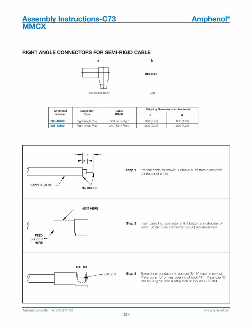
338Amphenol Corporation Tel: 800-627-7100 www.amphenolrf.com
RIGHT ANGLE CONNECTORS FOR SEMI-RIGID CABLE
Step 1 Prepare cable as shown. Remove burrs from outer/innerconductor of cable.
Step 2 Insert cable into connector until it bottoms on shoulder ofbody. Solder outer conductor (Sn-60) recommended.
Step 3 Solder inner conductor to contact (Sn-60 recommended).Place cover “b” on rear opening of body “A”. Press cap “b”into housing “a” with a flat punch or tool #908-50100.
Connector Body Cap
d
COPPER JACKETNO BURRS
c
HEAT HERE
SOLDERHERE
FEED
SOLDER
a b
Amphenol Connector Cable Stripping Dimensions, inches (mm)
Number Type RG-/U c d
908-43400 Right Angle Plug .086 Semi-Rigid .090 (2.29) .050 (1.27)
908-43600 Right Angle Plug .047 Semi-Rigid .090 (2.29) .050 (1.27)
Assembly Instructions-C73 Amphenol®
MMCX
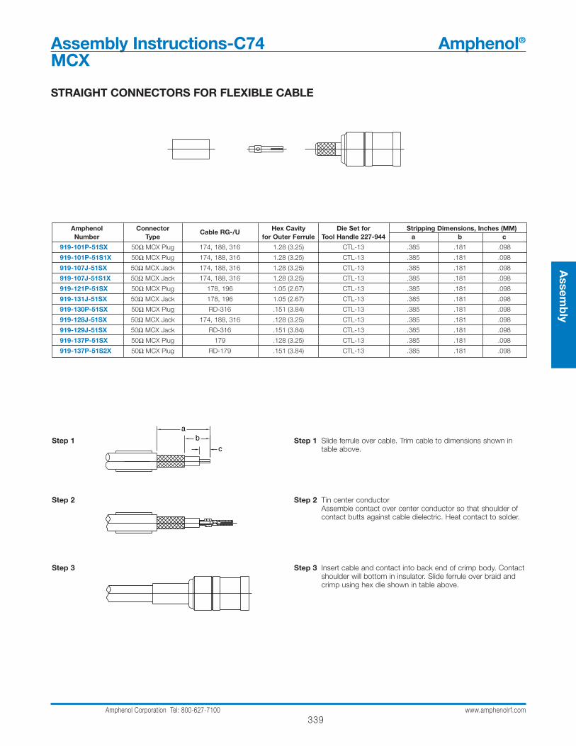
339Amphenol Corporation Tel: 800-627-7100 www.amphenolrf.com
Assem
bly
STRAIGHT CONNECTORS FOR FLEXIBLE CABLE
Amphenol Connector Cable RG-/U Hex Cavity Die Set for Stripping Dimensions, Inches (MM)Number Type for Outer Ferrule Tool Handle 227-944 a b c
919-101P-51SX 50Ω MCX Plug 174, 188, 316 1.28 (3.25) CTL-13 .385 .181 .098
919-101P-51S1X 50Ω MCX Plug 174, 188, 316 1.28 (3.25) CTL-13 .385 .181 .098
919-107J-51SX 50Ω MCX Jack 174, 188, 316 1.28 (3.25) CTL-13 .385 .181 .098
919-107J-51S1X 50Ω MCX Jack 174, 188, 316 1.28 (3.25) CTL-13 .385 .181 .098
919-121P-51SX 50Ω MCX Plug 178, 196 1.05 (2.67) CTL-13 .385 .181 .098
919-131J-51SX 50Ω MCX Jack 178, 196 1.05 (2.67) CTL-13 .385 .181 .098
919-130P-51SX 50Ω MCX Plug RD-316 .151 (3.84) CTL-13 .385 .181 .098
919-128J-51SX 50Ω MCX Jack 174, 188, 316 .128 (3.25) CTL-13 .385 .181 .098
919-129J-51SX 50Ω MCX Jack RD-316 .151 (3.84) CTL-13 .385 .181 .098
919-137P-51SX 50Ω MCX Plug 179 .128 (3.25) CTL-13 .385 .181 .098
919-137P-51S2X 50Ω MCX Plug RD-179 .151 (3.84) CTL-13 .385 .181 .098
Step 1 Slide ferrule over cable. Trim cable to dimensions shown intable above.
Step 2 Tin center conductorAssemble contact over center conductor so that shoulder ofcontact butts against cable dielectric. Heat contact to solder.
Step 3 Insert cable and contact into back end of crimp body. Contactshoulder will bottom in insulator. Slide ferrule over braid andcrimp using hex die shown in table above.
Step 1
Step 2
Step 3
Assembly Instructions-C74 Amphenol®
MCX

340Amphenol Corporation Tel: 800-627-7100 www.amphenolrf.com
Assembly Instructions-C75 Amphenol®
MCX
STRAIGHT CONNECTORS FOR SEMI-RIGID CABLE
Step 1 Prepare cable according to diagram. Remove burrs fromouter/inner conductors of cable.
Step 2 Solder center contact “a” to inner conductor of cable usingSn60 solder. Contact must butt on dielectric of cable asshown.
Step 3 Insert contact into body assembly “b” as shown. Holdingbody and cable firmly, apply heat as shown and feed solder(Sn-60) as indicated. Allow to cool. The dimension from thecontact tip to the end of the body should be .006 ±.007.
Contact Connector Body
APPLY HEAT
FEED SOLDER HERE
CONTACT MUST BUTT HERE
c
d
a b
Amphenol Connector Cable Stripping Dimensions, inches (mm)
Number Type RG-/U c d
919-114J-51SX Straight Jack .086 Semi-Rigid .118 .039
919-120P-51SX Straight Plug .086 Semi-Rigid .100 –

341Amphenol Corporation Tel: 800-627-7100 www.amphenolrf.com
Assem
bly
RIGHT ANGLE PLUGSFOR SEMI-RIGID CABLE
Amphenol Connector Cable Dim DimNumber Type RG/U c d
919-102P-51AX MCX Angle Plug .086 Semi Rigid .157 .051
919-103P-51AX MCX Angle Plug .141 Semi Rigid .157 .051
Step 1
Step 2
Step 3
Step 1 Clean cable end for .625"(16mm) min. length. Trim cable jacket and dielectric to dimension shown. Do not nick center conductor. Remove burrs from cable jacket and center conductor.
Step 2 Assemble cable into connector body. Bottom cable in connector body as shown. Solder cable to connector body as shown.
Step 3 Solder center conductor to contact as shown. Remove excess solder. Assemble cap and solder or lightly punch center of cap for retention in body.
.125(3.2)
solder here
dimple cap
cable jacketbottoms here
solder here
remove burrs
Assembly Instructions-C76 Amphenol®
MCX
c
d
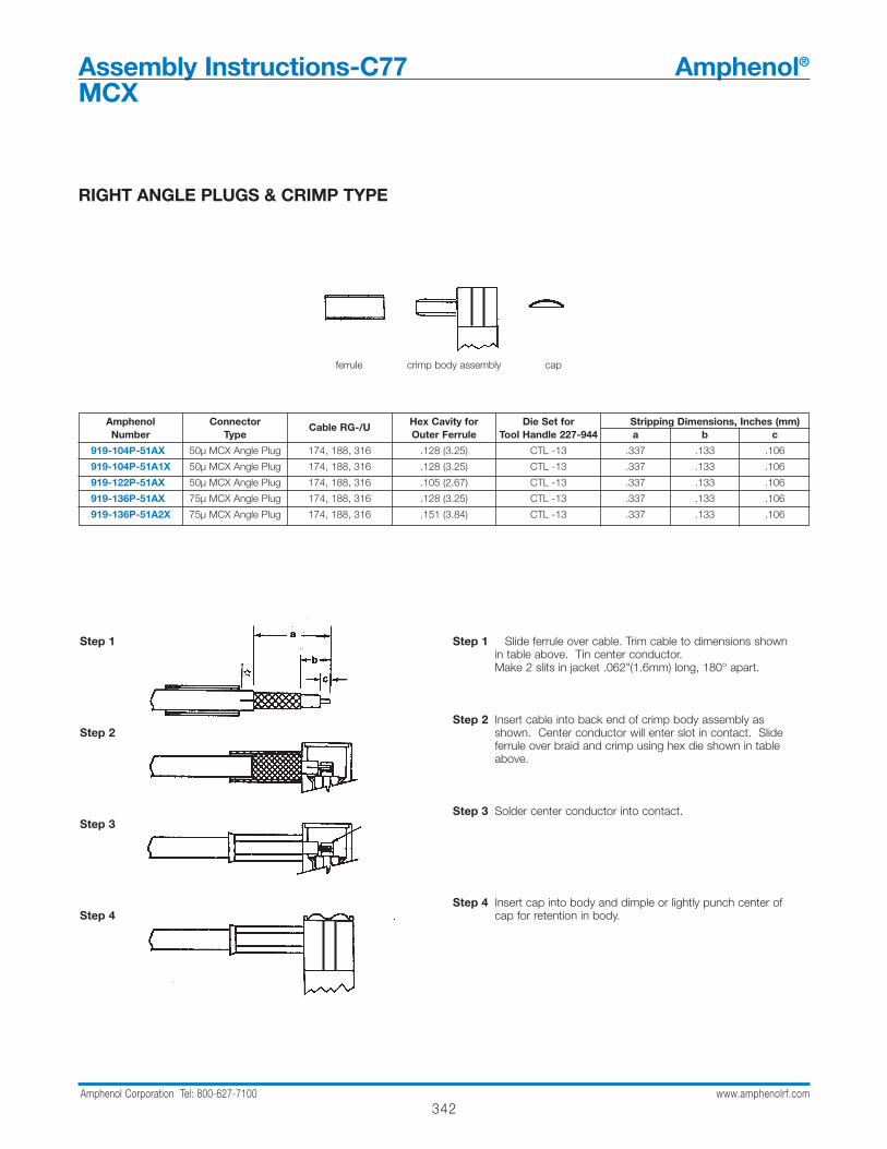
342Amphenol Corporation Tel: 800-627-7100 www.amphenolrf.com
RIGHT ANGLE PLUGS & CRIMP TYPE
Amphenol Connector Cable RG-/U Hex Cavity for Die Set for Stripping Dimensions, Inches (mm)Number Type Outer Ferrule Tool Handle 227-944 a b c
919-104P-51AX 50µ MCX Angle Plug 174, 188, 316 .128 (3.25) CTL -13 .337 .133 .106
919-104P-51A1X 50µ MCX Angle Plug 174, 188, 316 .128 (3.25) CTL -13 .337 .133 .106
919-122P-51AX 50µ MCX Angle Plug 174, 188, 316 .105 (2.67) CTL -13 .337 .133 .106
919-136P-51AX 75µ MCX Angle Plug 174, 188, 316 .128 (3.25) CTL -13 .337 .133 .106
919-136P-51A2X 75µ MCX Angle Plug 174, 188, 316 .151 (3.84) CTL -13 .337 .133 .106
Step 1 Slide ferrule over cable. Trim cable to dimensions shown in table above. Tin center conductor.Make 2 slits in jacket .062"(1.6mm) long, 180° apart.
Step 2 Insert cable into back end of crimp body assembly as shown. Center conductor will enter slot in contact. Slide ferrule over braid and crimp using hex die shown in table above.
Step 3 Solder center conductor into contact.
Step 4 Insert cap into body and dimple or lightly punch center of cap for retention in body.
Step 1
Step 2
Step 3
Step 4
ferrule crimp body assembly cap
Assembly Instructions-C77 Amphenol®
MCX
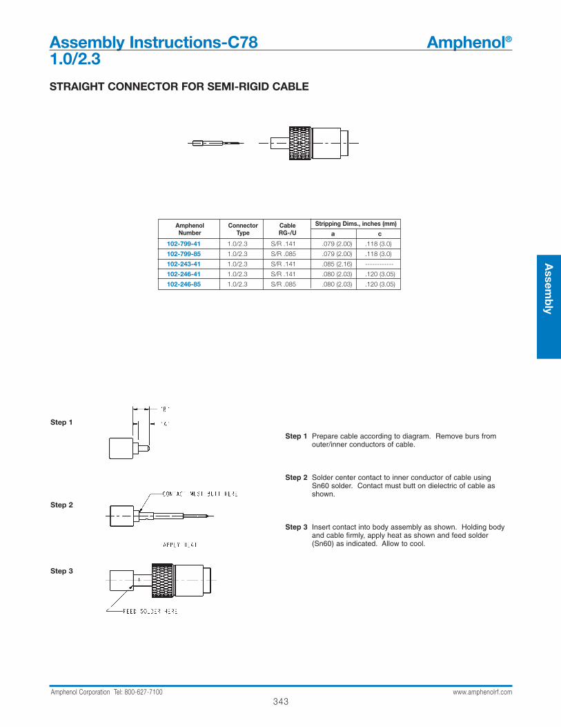
343Amphenol Corporation Tel: 800-627-7100 www.amphenolrf.com
Assem
bly
Assembly Instructions-C78 Amphenol®
1.0/2.3
Step 1 Prepare cable according to diagram. Remove burs fromouter/inner conductors of cable.
Step 2 Solder center contact to inner conductor of cable usingSn60 solder. Contact must butt on dielectric of cable asshown.
Step 3 Insert contact into body assembly as shown. Holding bodyand cable firmly, apply heat as shown and feed solder(Sn60) as indicated. Allow to cool.
Step 1
Step 2
Step 3
STRAIGHT CONNECTOR FOR SEMI-RIGID CABLE
Amphenol Connector Cable Stripping Dims., inches (mm)Number Type RG-/U a c
102-799-41 1.0/2.3 S/R .141 .079 (2.00) .118 (3.0)
102-799-85 1.0/2.3 S/R .085 .079 (2.00) .118 (3.0)
102-243-41 1.0/2.3 S/R .141 .085 (2.16) ------------
102-246-41 1.0/2.3 S/R .141 .080 (2.03) .120 (3.05)
102-246-85 1.0/2.3 S/R .085 .080 (2.03) .120 (3.05)
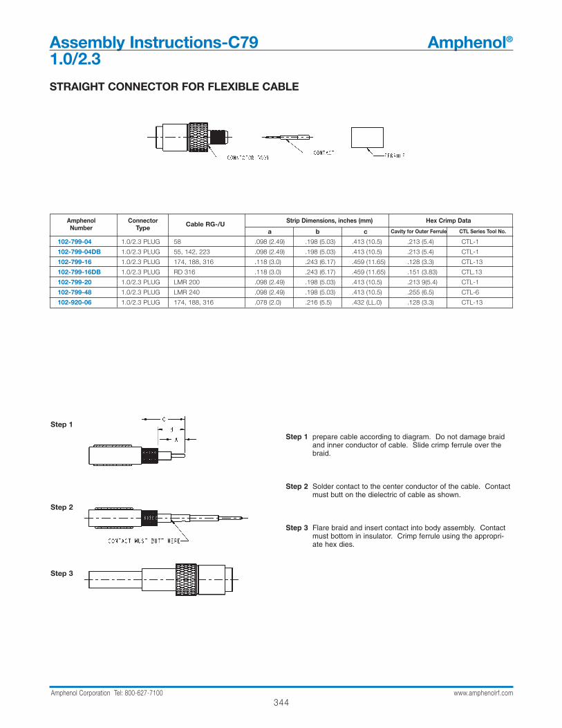
344Amphenol Corporation Tel: 800-627-7100 www.amphenolrf.com
Assembly Instructions-C79 Amphenol®
1.0/2.3
Step 1 prepare cable according to diagram. Do not damage braidand inner conductor of cable. Slide crimp ferrule over thebraid.
Step 2 Solder contact to the center conductor of the cable. Contactmust butt on the dielectric of cable as shown.
Step 3 Flare braid and insert contact into body assembly. Contactmust bottom in insulator. Crimp ferrule using the appropri-ate hex dies.
Step 1
Step 2
Step 3
STRAIGHT CONNECTOR FOR FLEXIBLE CABLE
Amphenol Connector Cable RG-/U Strip Dimensions, inches (mm) Hex Crimp DataNumber Type a b c Cavity for Outer Ferrule CTL Series Tool No.
102-799-04 1.0/2.3 PLUG 58 .098 (2.49) .198 (5.03) .413 (10.5) .213 (5.4) CTL-1
102-799-04DB 1.0/2.3 PLUG 55, 142, 223 .098 (2.49) .198 (5.03) .413 (10.5) .213 (5.4) CTL-1
102-799-16 1.0/2.3 PLUG 174, 188, 316 .118 (3.0) .243 (6.17) .459 (11.65) .128 (3.3) CTL-13
102-799-16DB 1.0/2.3 PLUG RD 316 .118 (3.0) .243 (6.17) .459 (11.65) .151 (3.83) CTL.13
102-799-20 1.0/2.3 PLUG LMR 200 .098 (2.49) .198 (5.03) .413 (10.5) .213 9(5.4) CTL-1
102-799-48 1.0/2.3 PLUG LMR 240 .098 (2.49) .198 (5.03) .413 (10.5) .255 (6.5) CTL-6
102-920-06 1.0/2.3 PLUG 174, 188, 316 .078 (2.0) .216 (5.5) .432 (LL.0) .128 (3.3) CTL-13

345Amphenol Corporation Tel: 800-627-7100 www.amphenolrf.com
Assem
bly
Assembly Instructions-C80 Amphenol®
1.0/2.3
Step 1 Prepare cable according to diagram. Do not damage braidand inner conductor of cable. Slide crimp ferrule over thebraid
Step 2 Flare braid and insert into body. Slide crimp ferrule overbody and crimp the ferrule using appropriate crimp tool anddie set.
Step 3 solder inner conductor to contact (Sn60 recommended).Place cap on rear opening of body. Press cap into housing.
Step 1
Step 2
Step 3
RIGHT ANGLE CONNECTOR FOR FLEXIBLE CABLE
Amphenol Connector Cable RG-/U Strip Dimensions, inches (mm) Hex Crimp DataNumber Type a b c Cavity for Outer Ferrule CTL Series Tool No.
102-799-104 1.0/2.3 ANGLE PLUG 58 .098 (2.48) .198 (5.02) .414 (10.5) .213 (5.4) CTL-1
102-799-104DB 1.0/2.3 ANGLE PLUG 55, 142, 223 .098 (2.48) .198 (5.02) .414 (10.5) .213 (5.4) CTL-1
102-799-116DB 1.0/2.3 ANGLE PLUG RD 316 .098 (2.48) .198 (5.02) .414 (10.5) .151 (3.83) CTL-13
102-799-118 1.0/2.3 ANGLE PLUG MINI-COAX. .078 (2.0) .216 (5.5) .432 (11.0) .105 (2.67) SX 660 0060
102-799-120 1.0/2.3 ANGLE PLUG LMR200 .098 (2.48) .198 (5.02) .414 (10.5) .213 (5.4) CTL-1
102-799-116 1.0/2.3 ANGLE PLUG 174, 188, 316 .098 (2.48) .198 (5.02) .414 (10.5) .128 (3.3) CTL-13
102-907-06 1.0/2.3 ANGLE JACK 174, 188, 316 .078 (2.0) .216 (5.5) .432 (11.0) .128 (3.3) CTL-13
102-907-34 1.0/2.3 ANGLE JACK L910/34, RG180 .078 (2.0) ,216 (5.5) .432 (11.0) .213 (5.4) CTL-1
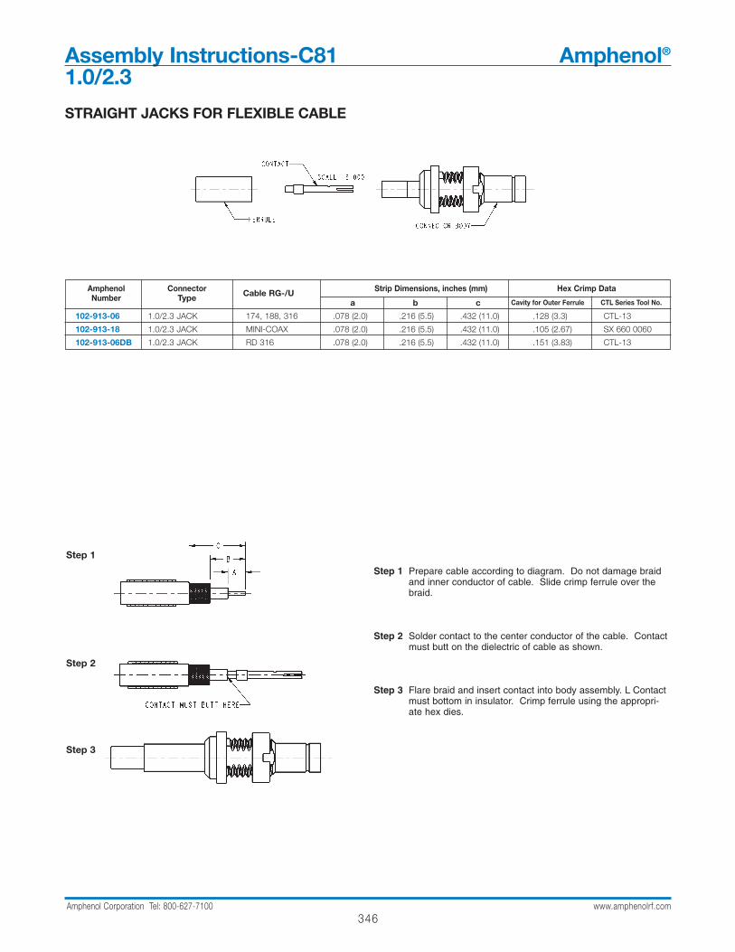
346Amphenol Corporation Tel: 800-627-7100 www.amphenolrf.com
Assembly Instructions-C81 Amphenol®
1.0/2.3
Step 1 Prepare cable according to diagram. Do not damage braidand inner conductor of cable. Slide crimp ferrule over thebraid.
Step 2 Solder contact to the center conductor of the cable. Contactmust butt on the dielectric of cable as shown.
Step 3 Flare braid and insert contact into body assembly. L Contactmust bottom in insulator. Crimp ferrule using the appropri-ate hex dies.
Step 1
Step 2
Step 3
STRAIGHT JACKS FOR FLEXIBLE CABLE
Amphenol Connector Cable RG-/U Strip Dimensions, inches (mm) Hex Crimp DataNumber Type a b c Cavity for Outer Ferrule CTL Series Tool No.
102-913-06 1.0/2.3 JACK 174, 188, 316 .078 (2.0) .216 (5.5) .432 (11.0) .128 (3.3) CTL-13
102-913-18 1.0/2.3 JACK MINI-COAX .078 (2.0) .216 (5.5) .432 (11.0) .105 (2.67) SX 660 0060
102-913-06DB 1.0/2.3 JACK RD 316 .078 (2.0) .216 (5.5) .432 (11.0) .151 (3.83) CTL-13
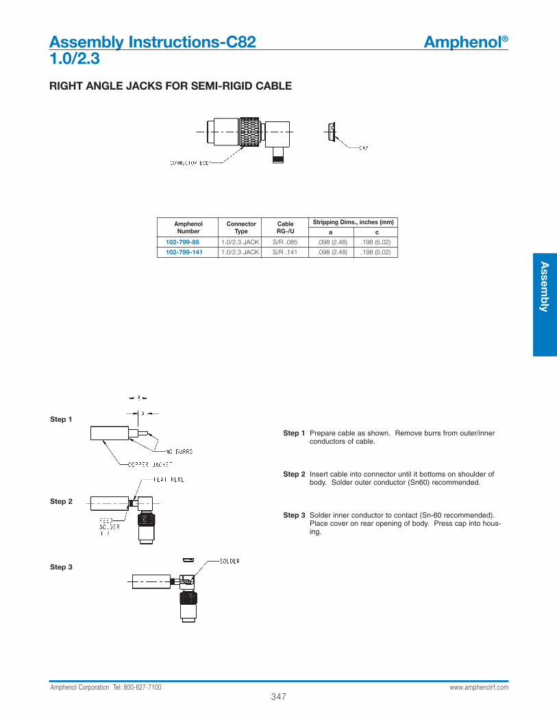
347Amphenol Corporation Tel: 800-627-7100 www.amphenolrf.com
Assem
bly
Assembly Instructions-C82 Amphenol®
1.0/2.3
Step 1 Prepare cable as shown. Remove burrs from outer/innerconductors of cable.
Step 2 Insert cable into connector until it bottoms on shoulder ofbody. Solder outer conductor (Sn60) recommended.
Step 3 Solder inner conductor to contact (Sn-60 recommended).Place cover on rear opening of body. Press cap into hous-ing.
Step 1
Step 2
Step 3
RIGHT ANGLE JACKS FOR SEMI-RIGID CABLE
Amphenol Connector Cable Stripping Dims., inches (mm)Number Type RG-/U a c
102-799-85 1.0/2.3 JACK S/R .085 .098 (2.48) .198 (5.02)
102-799-141 1.0/2.3 JACK S/R .141 .098 (2.48) .198 (5.02)
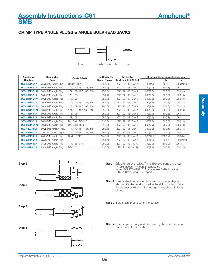
329Amphenol Corporation Tel: 800-627-7100 www.amphenolrf.com
Assem
bly
CRIMP TYPE ANGLE PLUGS & ANGLE BULKHEAD JACKS
Amphenol Connector Cable RG-/U Hex Cavity for Die Set for Stripping Dimensions, Inches (mm)Number Type Outer Ferrule Tool Handle 227-944 a b c
903-517P-71A 75Ω SMC Angle Plug Belden 735A .178(4.5) 227-1221-09 Cav. A .440(11.2) .180(4.57) .090(2.28)
903-289P-51A 50Ω SMB Angle Plug 174, 179, 187, 188, 316 .128(3.3) 227-1221-03 Cav. A .390(9.9) .150(3.8) .050(1.3)
903-289P-51A2 50Ω SMB Angle Plug 174, 179, 187, 188, 316 .128(3.3) 227-1221-03 Cav. A .390(9.9) .150(3.8) .050(1.3)
903-291P-51A 50Ω SMB Angle Plug 178, 196 .105(2.7) 227-1221-03 Cav. B .390(9.9) .150(3.8) .050(1.3)
903-291P-51A1 50Ω SMB Angle Plug 178, 196 .105(2.7) 227-1221-03 Cav. B .390(9.9) .150(3.8) .050(1.3)
903-367P-51A 50Ω SMB Angle Plug 174, 179, 187, 188, 316 .128(3.3) 227-1221-03 Cav. A .390(9.9) .150(3.8) .050(1.3)
903-367P-51A1 50Ω SMB Angle Plug 174, 179, 187, 188, 316 .128(3.3) 227-1221-03 Cav. A .390(9.9) .150(3.8) .050(1.3)
903-367P-51A2 50Ω SMB Angle Plug 174, 179, 187, 188, 316 .128(3.3) 227-1221-03 Cav. A .390(9.9) .150(3.8) .050(1.3)
903-368P-51A 50Ω SMB Angle Plug 178, 196 .105(2.7) 227-1221-03 Cav. B .390(9.9) .150(3.8) .050(1.3)
903-368P-51A1 50Ω SMB Angle Plug 178, 196 .105(2.7) 227-1221-03 Cav. B .390(9.9) .150(3.8) .050(1.3)
903-369P-51A 50Ω SMB Angle Plug Dbl. Braid RG-316 .151(3.8) 227-1221-37 Cav. B .390(9.9) .150(3.8) .050(1.3)
903-369P-51A2 50Ω SMB Angle Plug Dbl. Braid RG-316 .151(3.8) 227-1221-37 Cav. B .390(9.9) .150(3.8) .050(1.3)
903-422J-51A 50Ω SMB Ang.Blkh Jack 174, 179, 187, 188, 316 .128(3.3) 227-1221-03 Cav. A .390(9.9) .150(3.8) .050(1.3)
903-429P-51A 50Ω SMB Low Prof. Angl Plg 174, 179, 187, 188, 316 .128(3.3) 227-1221-03 Cav. A .400(10.2) .200(5.1) .050(1.3)
903-495P-71A 75Ω SMB Angle Plug Belden 9248 .324(8.2) 227-1221-32 Cav. A .500(12.7) .250(6.4) .250(6.4)
903-535P-71A 75Ω SMB Angle Plug 179 .178(4.5) 227-1221-09 Cav. A .440(11.2) .180(4.57) .090(2.28)
903-288P-52A 75Ω SMB Angle Plug 174, 188, 316 .128(3.3) 227-1221-03 Cav. A .390(9.9) .150(3.2) .050(1.3)
903-362P-52A1 75Ω SMB Angle Plug RD-316 .151(3.8) 227-1221-37 Cav. B .390(9.9) .150(3.2) .050(1.3)
Step 1 Slide ferrule over cable. Trim cable to dimensions shown in table above. Tin center conductor. for P/N 903-429P-51A only, make 2 slits in jacket .062"(1.6mm) long, 180° apart.
Step 2 Insert cable into back end of crimp body assembly as shown. Center conductor will enter slot in contact. Slide ferrule over braid and crimp using hex die shown in table above.
Step 3 Solder center conductor into contact.
Step 4 Insert cap into body and dimple or lightly punch center of cap for retention in body.
Step 1
Step 2
Step 3
Step 4
ferrule crimp body assembly cap
Assembly Instructions-C61 Amphenol®
SMB
Top Related