


Languages
Pages
Legal

Argentine Symposium on
Ontologies and their
Applications
44 Jornadas Argentinas de Informática
Sociedad Argentina de Informática (SADIO)
Rosario, Argentina
September 2-3, 2015

2015 for the individual papers by the papers’ authors. Copying permitted for private and academic purposes. Re-publication of material from this volume requires permission by the copyright owners. This volume is published and copyrighted by its editors.
II

Preface
This proceedings contents the papers accepted for presentation at SAOA 2015, the 1st
Argentine Symposium on Ontologies and their Applications (Simposio Argentino de
Ontologías y sus Aplicaciones), held on August 2-3, 2015 in Rosario, Argentina, at the
Universidad Nacional de Rosario - Facultad de Ciencias Exactas, Ingeniería y Agrimensura
(FCEIA-UNR). SAOA 2015 was part of the 44th JAIIO, the 44th Argentine Conference on
Informatics, organized by SADIO. JAIIO is organized as a series of thematic symposia including
topics such as software engineering, artificial intelligence, technology, agroinformatics, high
performance computing, industrial informatics, free software, law, health, information society,
and a students contest.
The Argentine Symposium on Ontologies and their Applications aims at providing a meeting
point among researchers from different fields as well as professionals from industries having
interest on ontologies. SAOA encourages the submission of original contributions ranging
from academic research to industrial and business applications having a significant impact as
well as lessons learned and best practices in ontology development. This is the first national
symposium on the topic of ontologies. We hope it will provide the motivation needed to
advance research on this interesting and influential topic.
We are very grateful to the authors for submitting their works, to all the program committee
members for doing an excellent job and to all the people involved in the JAIIO organization,
represented by Prof. Diego Milone, from Sinc(i) - FICH-UNL/CONICET, Prof. Pablo Granito,
from CIFASIS - CONICET/UNR; and Prof. Rosita Wachenchauzer, President of SADIO, for
providing the guidance and support along the way.
Our special thanks are also addressed to the invited speakers Prof. Giancarlo Guizzardi and
Prof. João Paulo Andrade Almeida.
September, 2015 Horacio Leone
Pablo Fillotrani
III

Chairs
Fillotrani, Pablo (LISSI-DCIC-UNS, CIC)
Leone, Horacio (INGAR-Dpto ISI, CONICET- FRSF UTN)
Program Committee
Ale, Mariel - CIDISI, Facultad Regional Santa Fe, UTN, (Argentina)
Ballejos, Luciana - CIDISI, Facultad Regional Santa Fe,UTN, (Argentina)
Caliusco, María Laura - CIDISI, Facultad Regional Santa Fe,UTN, (Argentina)
Cecchi, Laura Andrea – Universidad Nacional del Comahue, Facultad de Informática,
(Argentina)
Cenci, Karina – Universidad Nacional del Sur, (Argentina)
Chiotti, Omar - INGAR (CONICET/UTN), (Argentina)
Diaz Pace, Andres, ISISTAN-CONICET, UNICEN University (Argentina)
Estevez, Elsa - United Nations University - Operating Unit on Policy-driven Electronic
Governance (UNU-EGOV)
Galli, María Rosa - INGAR (CONICET/UTN), (Argentina)
Gonnet, Silvio - INGAR (CONICET/UTN), (Argentina)
Gómez, Sergio Alejandro - Universidad Nacional del Sur, (Argentina)
Guarino, Nicola - ISTC-CNR Laboratory for Applied Ontology, Trento, (Italy)
Guizzardi, Giancarlo - Universidade Federal do Espíritu Santo (UFES), (Brasil)
Guizzardi, Renata - Universidade Federal do Espíritu Santo (UFES), (Brasil)
Gutiérrez, Claudio C. -Computer Science Department, Universidad de Chile (Chile)
Gutierrez, Milagros - CIDISI, Facultad Regional Santa Fe, UTN, (Argentina)
Henning, Gabriela - INTEC (CONICET,UNL), (Argentina)
Keet, C. Maria - University of Cape Town, (Sudáfrica)
Montejano, Germán - Universidad Nacional de San Luis (Argentina)
Motz, Regina - Universidad de La República, (Uruguay)
Olsina, Luis - GIDIS_Web, Grupo de I+D en Ingeniería de Software y Web Facultad de
Ingeniería, UNLPam,(Argentina)
Parente de Oliveira, José María - Departamento de Ciencias de la Computación, Instituto
tecnológico Aeronáutico,(Brasil)
Rico, Mariela - CIDISI, Facultad Regional Santa Fe, UTN, (Argentina)
Vegetti, Marcela - INGAR (CONICET/UTN), (Argentina)
Villarreal, Pablo - CIDISI, Facultad Regional Santa Fe, UTN, (Argentina)
IV

Invited Talks
Using UFO as a Reference Ontology in the (Re)Design of Enterprise Modelling
Languages
João Paulo Andrade Almeida
Ontology and Conceptual Modeling Group (NEMO), Computer Science Department - Federal University
of Espirito Santo (UFES), Vitória, Brazil
Pattern-Based Ontology Engineering Giancarlo Guizzardi
Ontology and Conceptual Modeling Group (NEMO), Federal University of Espirito Santo (UFES), Vitória,
Brazil & Laboratory of Applied Ontology, Institute for Cognitive Science and Technology (ISTC), Italian
National Research Council (CNR), Trento, Italy
V
Using UFO as a Reference Ontology in the (Re)Design of
Enterprise Modelling Languages
João Paulo Andrade Almeida
Ontology and Conceptual Modeling Group (NEMO),
Computer Science Department
Federal University of Espirito Santo (UFES), Vitória, Brazil
Abstract. Conceptual modeling has been considered a key activity in enterprise
architecture and information systems engineering, and comprises the use of dia-
grammatic languages for communication, understanding and problem
solving regarding a universe of discourse. The effectiveness of a modeling
language for the aforementioned tasks is strongly related to the
language's domain appropriateness, i.e., to the language's ability to
express the relevant characteristics of the domain at hand. A language
designer must, therefore, understand the phenomena (or domain) that should
be covered by the language and propose symbolic structures that will
empower prospective language users to efficiently carry out certain tasks
concerning the represented phenomena. This requires the design of a
language with some form of correspondence between its constructs and
things in the external world, which we call real-world semantics.
Although essential to language design and semantic interoperability tasks,
the real-world semantics of conceptual modeling languages for the
enterprise is often defined only informally with no rigor or
methodological support for the language designer. As a consequence, a
number of language issues may arise, including lack of semantic clarity
and expressiveness, which ultimately affect the language's ability to
serve as a basis for communication, analysis and transformation.
In this tutorial, we will discuss advances in the last decade concerning
the application of reference ontologies to address these issues. We will
show how well-founded reference ontologies can serve to inform the design
and revision of enterprise modeling languages. In order to provide a solid
basis for reference ontologies, we will discuss the role of a foundational
ontology in this process (the Unified Foundational Ontology, UFO). A
number of concrete cases of language revision will be discussed involving
ArchiMate and other languages, encompassing different enterprise
architectural domains (such as services, capabilities, goals,
organizational structure, etc.).
Short Bio. João Paulo Andrade Almeida is associate professor at the Com-
puter Science Department of the Federal University of Espírito Santo, Brazil.
Proceeding of SAOA 2015 Copyright © 2015 held by the author(s) VI

He is a member of the Ontology and Conceptual Modelling Research Group
(NEMO) .
He joined the Centre for Telematics and Information Technology at the Uni-
versity of Twente in September 2001, and received his Ph.D. from that universi-
ty in 2006, with the Ph.D. thesis entitled Model-Driven Design of Distributed
Applications. During 2006, he worked as a Scientific Researcher for the
Telematica Instituut on the application of model-driven approaches to the de-
sign of services and service-oriented architectures. He has participated in the
European SPICE IST and MODA-TEL IST projects, in the Dutch Freeband
WASP project and in the AMIDST project. Since 2007, he has been working on
the application of ontologies in enterprise architecture and enterprise modeling.
He has served as principal researcher in a CNPq/FAPES PRONEX project, as
well as Dean of the Graduate School in Computer Science at the Federal Uni-
versity of Espírito Santo (2011-2013).
Proceeding of SAOA 2015 Copyright © 2015 held by the author(s) VII

Pattern-Based Ontology Engineering
Giancarlo Guizzardi
Ontology and Conceptual Modeling Group (NEMO),
Federal University of Espirito Santo (UFES), Vitória, Brazil
&
Laboratory of Applied Ontology,
Institute for Cognitive Science and Technology (ISTC),
Italian National Research Council (CNR), Trento, Italy
Abstract. In his ACM Turing Award Lecture entitled “The Humble Program-
mer”, E. W. Dijkstra discusses the sheer complexity one has to deal with when
programming large computer systems. His article represented an open call for
an acknowledgement of the complexity at hand and for the need of more so-
phisticated techniques to master this complexity. Dijkstra’s advice is timely and
even more insightful in our current scenario, in which semantic interoperability
becomes a pervasive force driving and constraining the process of creating in-
formation systems in increasingly complex combinations of domains.
More and more, information systems are created either by combining exist-
ing autonomously developed subsystem, or are created to eventually serve as
components in multiple larger yet-to-be-conceived systems. In this scenario, in-
formation systems engineering, in particular, and rational governance, in gen-
eral, cannot succeed without the support of a particular type of discipline. A
discipline devoted to establish well-founded theories, principles, as well as
methodological and computational tools for supporting us in the tasks of under-
standing, elaborating and precisely representing the nature of conceptualizations
of reality, as well as in tasks of negotiating and safely establishing the correct
relations between different conceptualizations of reality. The discipline to ad-
dress the aforementioned challenges is the discipline of Ontology Engineering.
In this talk, I would like to address a particular set of complexity manage-
ment tools for the engineering of ontologies that can properly serve as reference
conceptual models for interoperability. This set includes: Ontological Patterns,
as methodological mechanisms for encoding basic ontological micro-theories;
(ii) Ontology Pattern Languages, as systems of representation that take onto-
logical patterns as higher-granularity modeling primitives, (iii) Ontological An-
ti-Patterns as structures that can be used to systematically identify recurrent
possible deviations between the set of valid state of affairs admitted by a model
and the set of state of affairs actually intended by the stakeholders.
Short Bio. Giancarlo Guizzardi holds a PhD (with the highest distinction) in
Computer Science from the University of Twente, in The Netherlands. He is
one of the leaders of the Ontology and Conceptual Modeling Group (NEMO) in
Brazil. He is also an Associate Researcher at the Laboratory of Applied Ontolo-
gy (ISTC-CNR), Trento, Italy. Between 2013 and 2015, he was a Visiting Pro-
fessor at the University of Trento, Italy. He has been doing research in ontology
Proceeding of SAOA 2015 Copyright © 2015 held by the author(s) VIII

and conceptual modeling for the past 19 years and has published circa 176 pub-
lications in these areas (including 9 award-wining publications). Among the
best-known results of his lab, we have the foundational ontology UFO and the
conceptual modeling language OntoUML. Over the years, he has contributed to
the ontology and conceptual modeling communities in roles such as keynote
speaker (e.g., ER), general chair (e.g., FOIS), tutorialist (e.g., CAISE, ER),
Program Board Member (e.g., CAISE, ER) and PC Chair (e.g., FOIS, EDOC).
Moreover, he is an associate editor of the Applied Ontology journal and has
been a member of editorial boards of international journals such as Require-
ments Engineering and Semantic Web. Furthermore, between 2012 and 2014,
he was an elected member of the Executive Council of the International Associ-
ation of Ontologies and its Applications (IAOA) and currently is a member of
its Advisory Board (since 2014). Finally, he has been involved in technology
transfer projects in sectors such as Telecommunications, Software Engineering,
Digital Advertisement, Product Recommendation, Digital Journalism, Complex
Media Management and Energy.
Proceeding of SAOA 2015 Copyright © 2015 held by the author(s) IX
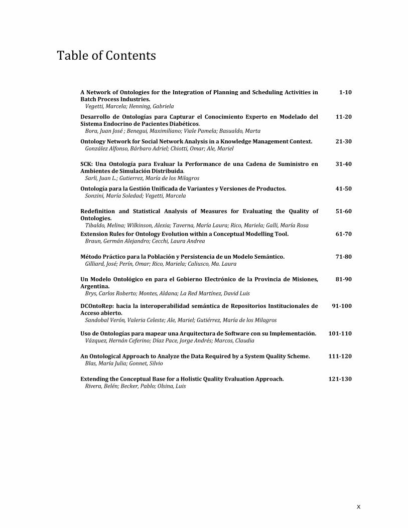
Table of Contents
A Network of Ontologies for the Integration of Planning and Scheduling Activities in Batch Process Industries.
Vegetti, Marcela; Henning, Gabriela
1-10
Desarrollo de Ontologías para Capturar el Conocimiento Experto en Modelado del Sistema Endocrino de Pacientes Diabéticos.
Bora, Juan José ; Benegui, Maximiliano; Viale Pamela; Basualdo, Marta
11-20
Ontology Network for Social Network Analysis in a Knowledge Management Context. González Alfonso, Bárbaro Adriel; Chiotti, Omar; Ale, Mariel
21-30
SCK: Una Ontología para Evaluar la Performance de una Cadena de Suministro en Ambientes de Simulación Distribuida.
Sarli, Juan L.; Gutierrez, María de los Milagros
31-40
Ontología para la Gestión Unificada de Variantes y Versiones de Productos. Sonzini, María Soledad; Vegetti, Marcela
41-50
Redefinition and Statistical Analysis of Measures for Evaluating the Quality of Ontologies.
Tibaldo, Melina; Wilkinson, Alexia; Taverna, María Laura; Rico, Mariela; Galli, María Rosa
51-60
Extension Rules for Ontology Evolution within a Conceptual Modelling Tool. Braun, Germán Alejandro; Cecchi, Laura Andrea
61-70
Método Práctico para la Población y Persistencia de un Modelo Semántico. Gilliard, José; Perín, Omar; Rico, Mariela; Caliusco, Ma. Laura
71-80
Un Modelo Ontológico en para el Gobierno Electrónico de la Provincia de Misiones, Argentina.
Brys, Carlos Roberto; Montes, Aldana; La Red Martínez, David Luis
81-90
DCOntoRep: hacia la interoperabilidad semántica de Repositorios Institucionales de Acceso abierto.
Sandobal Verón, Valeria Celeste; Ale, Mariel; Gutiérrez, María de los Milagros
91-100
Uso de Ontologías para mapear una Arquitectura de Software con su Implementación. Vázquez, Hernán Ceferino; Díaz Pace, Jorge Andrés; Marcos, Claudia
101-110
An Ontological Approach to Analyze the Data Required by a System Quality Scheme. Blas, María Julia; Gonnet, Silvio
111-120
Extending the Conceptual Base for a Holistic Quality Evaluation Approach. Rivera, Belén; Becker, Pablo; Olsina, Luis
121-130
X
A network of ontologies for the integration of planning
and scheduling activities in batch process industries
Marcela Vegetti 1, Gabriela Henning2
1 INGAR(CONICET/UTN), Avellaneda 3657, Santa Fe 3000, Argentinta
2 INTEC (CONICET,UNL), Ruta Nacional 168, km 461,5, Santa Fe 3000, Argentina
Abstract. In the last decades, the integration of informatics applications sup-
porting planning, scheduling and control has been a serious concern of the in-
dustrial community. Many standards have been developed to tackle this issue
by addressing the exchange of data between the scheduling function and its
immediate lower and upper levels in the planning pyramid. However, a more
comprehensive approach is required to tackle integration problems, since this
matter entails much more than data exchange. So, this article presents an onto-
logical framework that provides the foundations to reach an effective interoper-
ability among the various applications linked to scheduling activities.
1 Introduction
Despite over twenty years of research in batch scheduling, advanced scheduling sup-
port systems are not very common in the chemical industry yet. In addition, most of
the available commercial systems are not based on the solution methodologies that
academia has developed. One of the reasons why academic approaches are not adopt-
ed in industry is the fact that decision support tools do not integrate with the enter-
prise and manufacturing applications because they rely upon quite different
knowledge representations. In the last decades, the integration of informatics applica-
tions supporting planning, scheduling and control has been a serious concern of the industrial community. The ISA-88 [1] and ISA-95 [2] standards have been developed
to tackle this issue by addressing the exchange of data between the scheduling func-
tion and its immediate lower and upper levels in the planning pyramid. However, a
more comprehensive approach is required to address integration problems, since this
matter entails much more than data exchange. In last decade, ontologies have been
considered an effective solution to interoperability problems in many domains. There-
fore, this article presents an ontological framework that provides the foundations to
reach an effective interoperability among the various applications linked to schedul-ing activities, focusing on one of the ontologies of such framework.
The paper is organized as follows. Section 2 points out some of the problems of
dealing with multiple knowledge representations in the scheduling domain. Section 3
introduces the ontological approach that is proposed to address integration problems.
Proceeding of SAOA 2015 Copyright © 2015 held by the author(s) 1
By means of example, Section 4 describes the ontology that was developed to formal-
ize the Resource Task Network (RTN) [3] model, which is one of the components of
the ontology network that is proposed in this contribution. The proposed formaliza-
tion is a definitional extension of the Process Specification Language (PSL) [4]. Fi-
nally, section 5 presents some concluding remarks.
2 Different knowledge representations in the scheduling field
Many academic approaches addressing scheduling problems resort to intermediate
representations, like the state-task (STN) or resource-task (RTN) networks (See Figs.
1 and 2 of [5]), before developing the mathematical model that indeed solves the
problem. However, this representation does not have a direct mapping to the master
data that is usually employed in industry. Thus, the human scheduler has to manually create the STN/RTN graphical models from data that is spread in different tables of
the enterprise databases.
On the other hand, in the industrial domain, the most important input for the
scheduling problem is the ISA-88 master recipe, which provides the set of data that
uniquely defines the production requirements of a specific product batch. Recipes are
recursive structures containing five components: Header, Formula, Procedure,
Equipment requirements and Other Information. See for example Fig. 1, which de-
picts the master recipes of P1 and P2, which are the final products of the STN shown in Fig. 2 of [5]. Fig. 1 shows that the procedure component of the P1 master recipe is
defined in terms of the T2, T1 and T3 operations. The INT3 recipe entity is also
shown in Fig. 1 and the ones corresponding to the other intermediates can be found in
[6]. An analysis of Fig. 1, the material in [6], along with Figs. 1 and 2 of [5] shows
that these recipe representations are quite different and that a direct mapping is not
possible. On top of the recipe information, the scheduling problem needs additional
input data, such as demands to be fulfilled, plant topology with unit features, etc. This
last type of information is not represented neither in the STN/RTN graphs nor in the ISA-88 recipe model. Usually, industry specifies it in the so called physical model
proposed by ISA-88, while in academia it is handled in an informal way that is not
machine procesable and can lead to misinterpretations.
Having all this input information, a mathematical model is built and then solved.
The resulting production schedule needs to be communicated to the adjacent levels in
the planning pyramid: (i) to the lower process control layer to materialize batch exe-
cution and (ii) to the upper production planning and control (PPC) level for plan man-
agement activities. In practice, the results included in the solver output file need to be translated into the control recipe (the one that according to ISA-88 standard is em-
ployed by the control system to perform batch execution) and into the operations
schedule, an explicit representation of the schedule according to the ISA-95 standard.
As a result, it can be seen that in order to perform scheduling activities and to articu-
late them within the planning pyramid, several knowledge representations and models
need to interplay. For instance, to transform a given master recipe into a control one,
the procedure that is conceptualized in Fig. 2 would need to be executed (actually,
such an approach was never made explicit by researchers devoted to the industrial scheduling field and it is presented in this contribution). Currently, the translation
Proceeding of SAOA 2015 Copyright © 2015 held by the author(s) 2
A network of ontologies for the integration of planning and scheduling activities in batch process industries

from one representation to another is manually done, in the few cases it is indeed
carried out. In fact, none of the academic proposals take into account the automatic
translation of the solver output file into representations that are useful from an indus-
trial point of view, i.e. control recipes and explicit schedule representations. In addi-
tion to the manual translation workload, these heterogeneous data models employ
distinct terms to refer to the same concepts. Besides these semantic issues, since the models are not formal, they cannot be interpreted by a computer and can also be am-
biguous. Moreover, an analysis of the ISA-88 and ISA-95 standards [7] reveals some
overlappings on the information and activities handled by them (e.g. product defini-
tion vs. recipe specification; equipment capability vs. physical model), which disclos-
es some collision points. The problems pointed out in the previous paragraphs are
some of the difficulties preventing the integration of scheduling activities within the
planning pyramid and, more specifically, precluding the adoption of advanced sched-
uling approaches in industry.
Fig. 1. Recipe entities for products P1, P2 and INT3
Fig. 2. Data manipulation and model translation associated with scheduling
Proceeding of SAOA 2015 Copyright © 2015 held by the author(s) 3
A network of ontologies for the integration of planning and scheduling activities in batch process industries
3 Ontological approach that supports scheduling activities
In order to tackle the problems posed in the previous section an ontological approach
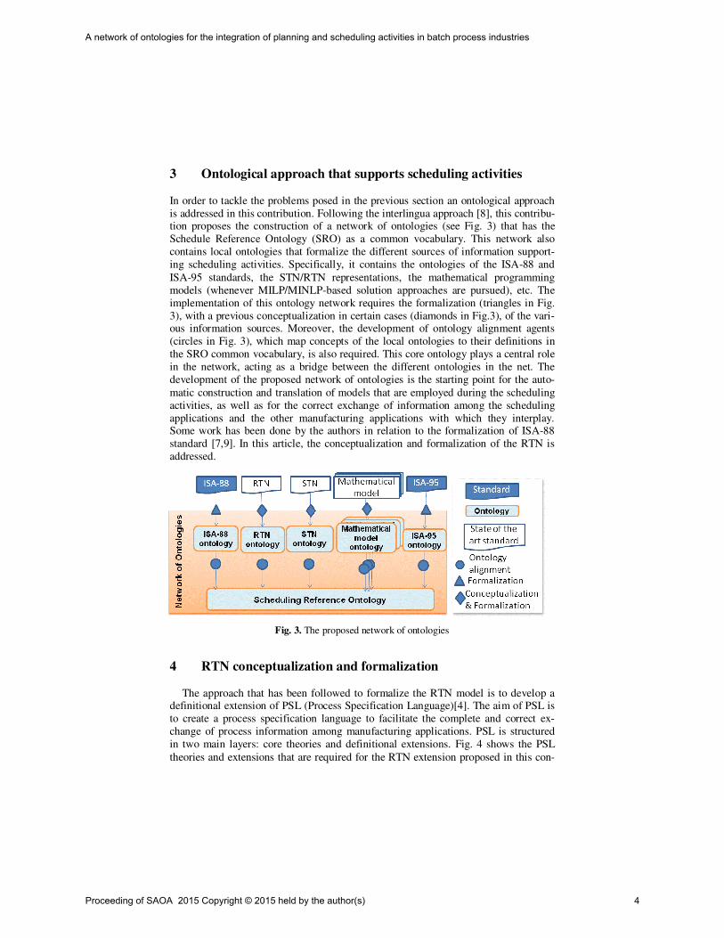
is addressed in this contribution. Following the interlingua approach [8], this contribu-tion proposes the construction of a network of ontologies (see Fig. 3) that has the
Schedule Reference Ontology (SRO) as a common vocabulary. This network also
contains local ontologies that formalize the different sources of information support-
ing scheduling activities. Specifically, it contains the ontologies of the ISA-88 and
ISA-95 standards, the STN/RTN representations, the mathematical programming
models (whenever MILP/MINLP-based solution approaches are pursued), etc. The
implementation of this ontology network requires the formalization (triangles in Fig.
3), with a previous conceptualization in certain cases (diamonds in Fig.3), of the vari-ous information sources. Moreover, the development of ontology alignment agents
(circles in Fig. 3), which map concepts of the local ontologies to their definitions in
the SRO common vocabulary, is also required. This core ontology plays a central role
in the network, acting as a bridge between the different ontologies in the net. The
development of the proposed network of ontologies is the starting point for the auto-
matic construction and translation of models that are employed during the scheduling
activities, as well as for the correct exchange of information among the scheduling
applications and the other manufacturing applications with which they interplay. Some work has been done by the authors in relation to the formalization of ISA-88
standard [7,9]. In this article, the conceptualization and formalization of the RTN is
addressed.
Fig. 3. The proposed network of ontologies
4 RTN conceptualization and formalization
The approach that has been followed to formalize the RTN model is to develop a definitional extension of PSL (Process Specification Language)[4]. The aim of PSL is
to create a process specification language to facilitate the complete and correct ex-
change of process information among manufacturing applications. PSL is structured
in two main layers: core theories and definitional extensions. Fig. 4 shows the PSL
theories and extensions that are required for the RTN extension proposed in this con-
Proceeding of SAOA 2015 Copyright © 2015 held by the author(s) 4
A network of ontologies for the integration of planning and scheduling activities in batch process industries
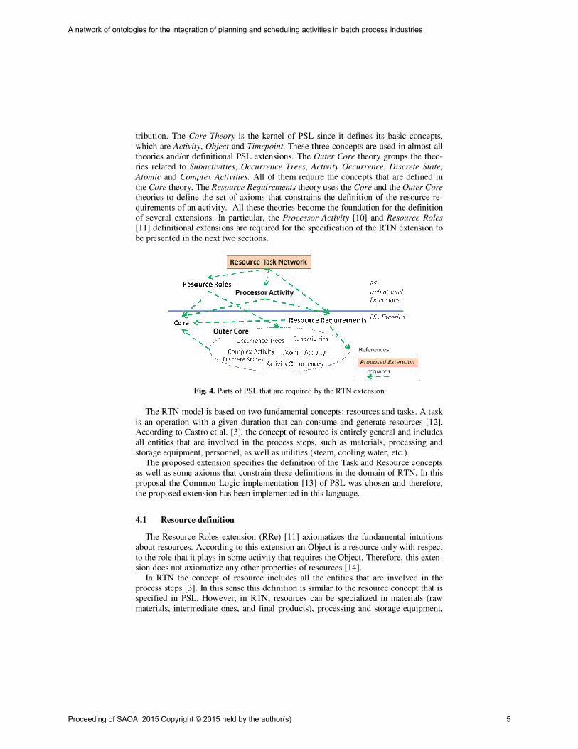
tribution. The Core Theory is the kernel of PSL since it defines its basic concepts,
which are Activity, Object and Timepoint. These three concepts are used in almost all
theories and/or definitional PSL extensions. The Outer Core theory groups the theo-
ries related to Subactivities, Occurrence Trees, Activity Occurrence, Discrete State,
Atomic and Complex Activities. All of them require the concepts that are defined in
the Core theory. The Resource Requirements theory uses the Core and the Outer Core theories to define the set of axioms that constrains the definition of the resource re-
quirements of an activity. All these theories become the foundation for the definition
of several extensions. In particular, the Processor Activity [10] and Resource Roles
[11] definitional extensions are required for the specification of the RTN extension to
be presented in the next two sections.
Fig. 4. Parts of PSL that are required by the RTN extension
The RTN model is based on two fundamental concepts: resources and tasks. A task
is an operation with a given duration that can consume and generate resources [12]. According to Castro et al. [3], the concept of resource is entirely general and includes
all entities that are involved in the process steps, such as materials, processing and
storage equipment, personnel, as well as utilities (steam, cooling water, etc.).
The proposed extension specifies the definition of the Task and Resource concepts
as well as some axioms that constrain these definitions in the domain of RTN. In this
proposal the Common Logic implementation [13] of PSL was chosen and therefore,
the proposed extension has been implemented in this language.
4.1 Resource definition
The Resource Roles extension (RRe) [11] axiomatizes the fundamental intuitions
about resources. According to this extension an Object is a resource only with respect
to the role that it plays in some activity that requires the Object. Therefore, this exten-
sion does not axiomatize any other properties of resources [14].
In RTN the concept of resource includes all the entities that are involved in the
process steps [3]. In this sense this definition is similar to the resource concept that is
specified in PSL. However, in RTN, resources can be specialized in materials (raw
materials, intermediate ones, and final products), processing and storage equipment,
Proceeding of SAOA 2015 Copyright © 2015 held by the author(s) 5
A network of ontologies for the integration of planning and scheduling activities in batch process industries
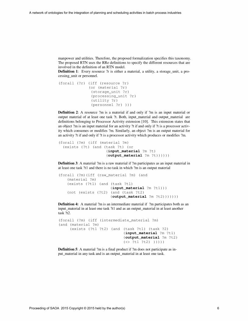
manpower and utilities. Therefore, the proposed formalization specifies this taxonomy.
The proposed RTN uses the RRe definitions to specify the different resources that are
involved in the definition of an RTN model.
Definition 1: Every resource ?r is either a material, a utility, a storage_unit, a pro-
cessing_unit or personnel.
(forall (?r) (iff (resource ?r)
(or (material ?r)
(storage_unit ?r)
(processing_unit ?r)
(utility ?r)
(personnel ?r) )))
Definition 2: A resource ?m is a material if and only if ?m is an input material or
output material of at least one task ?t. Both, input_material and output_material are
definitions belonging to Processor Activity extension [10]. This extension states that
an object ?m is an input material for an activity ?t if and only if ?t is a processor activ-
ity which consumes or modifies ?m. Similarly, an object ?m is an output material for
an activity ?t if and only if ?t is a processor activity which produces or modifies ?m.
(forall (?m) (iff (material ?m)
(exists (?t) (and (task ?t) (or
(input_material ?m ?t)
(output_material ?m ?t))))))
Definition 3: A material ?m is a raw material if ?m participates as an input material in
at least one task ?t1 and there is no task in which ?m is an output material
(forall (?m)(iff (raw_material ?m) (and
(material ?m)
(exists (?t1) (and (task ?t1)
(input_material ?m ?t1)))
(not (exists (?t2) (and (task ?t2)
(output_material ?m ?t2)))))))
Definition 4: A material ?m is an intermediate material if ?m participates both as an
input_material in at least one task ?t1 and as an output_material in at least another
task ?t2.
(forall (?m) (iff (intermediate_material ?m)
(and (material ?m)
(exists (?t1 ?t2) (and (task ?t1) (task ?2)
(input_material ?m ?t1)
(output_material ?m ?t2)
(<> ?t1 ?t2) )))))
Definition 5: A material ?m is a final product if ?m does not participate as in-
put_material in any task and is an output_material in at least one task.
Proceeding of SAOA 2015 Copyright © 2015 held by the author(s) 6
A network of ontologies for the integration of planning and scheduling activities in batch process industries
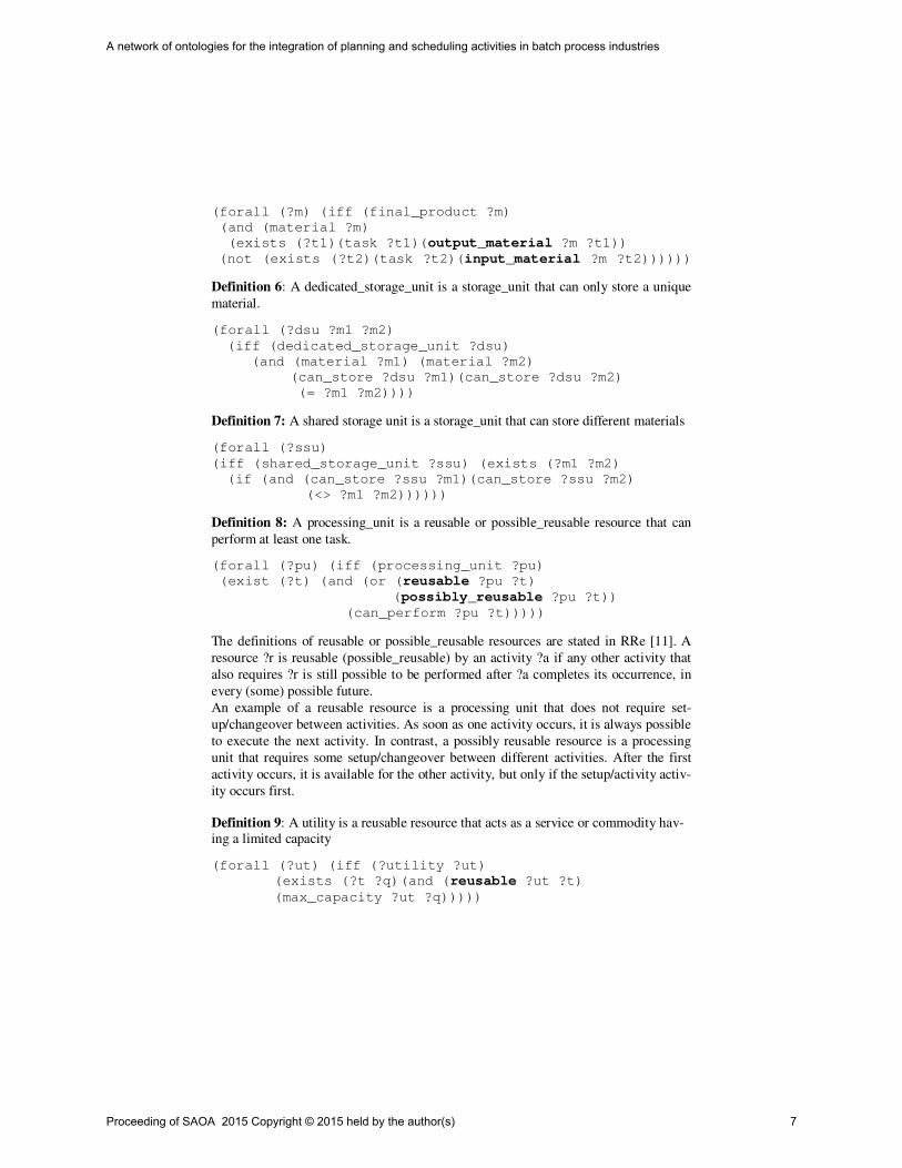
(forall (?m) (iff (final_product ?m)
(and (material ?m)
(exists (?t1)(task ?t1)(output_material ?m ?t1))
(not (exists (?t2)(task ?t2)(input_material ?m ?t2))))))
Definition 6: A dedicated_storage_unit is a storage_unit that can only store a unique
material.
(forall (?dsu ?m1 ?m2)
(iff (dedicated_storage_unit ?dsu)
(and (material ?m1) (material ?m2)
(can_store ?dsu ?m1)(can_store ?dsu ?m2)
(= ?m1 ?m2))))
Definition 7: A shared storage unit is a storage_unit that can store different materials
(forall (?ssu)
(iff (shared_storage_unit ?ssu) (exists (?m1 ?m2)
(if (and (can_store ?ssu ?m1)(can_store ?ssu ?m2)
(<> ?m1 ?m2))))))
Definition 8: A processing_unit is a reusable or possible_reusable resource that can
perform at least one task.
(forall (?pu) (iff (processing_unit ?pu)
(exist (?t) (and (or (reusable ?pu ?t)
(possibly_reusable ?pu ?t))
(can_perform ?pu ?t)))))
The definitions of reusable or possible_reusable resources are stated in RRe [11]. A
resource ?r is reusable (possible_reusable) by an activity ?a if any other activity that
also requires ?r is still possible to be performed after ?a completes its occurrence, in
every (some) possible future.
An example of a reusable resource is a processing unit that does not require set-
up/changeover between activities. As soon as one activity occurs, it is always possible
to execute the next activity. In contrast, a possibly reusable resource is a processing
unit that requires some setup/changeover between different activities. After the first
activity occurs, it is available for the other activity, but only if the setup/activity activ-
ity occurs first.
Definition 9: A utility is a reusable resource that acts as a service or commodity hav-
ing a limited capacity
(forall (?ut) (iff (?utility ?ut)
(exists (?t ?q) (and (reusable ?ut ?t)
(max_capacity ?ut ?q)))))
Proceeding of SAOA 2015 Copyright © 2015 held by the author(s) 7
A network of ontologies for the integration of planning and scheduling activities in batch process industries

4.2 Task definition
The other main concept of RTN model is task. This section deals with the definition
of this important concept and with the specification of a set of axioms that constrains
it.
Definitions 10-12: a task is a processor activity that has at least one input_material
and at least one output_material, which are consumed and created, respectively, in
given quantities.
(forall (?t) (iff (task ?t)(exists (?m ?m2 ?q1 ?q2)
(and (processor_activity ?t)
(input_material_demand ?m ?t ?q1)
(output_material_generation ?m2 ?t ?q2)))))
(forall (?m ?t ?q1)(iff (input_material_demand ?m ?t ?q1)
(and (material ?m) (task ?t) (input_material ?m ?t))))
(forall (?m ?t ?q1)
(iff (output_material_generation ?m ?t ?q1)
(and (material ?m) (task ?t)(output_material ?m ?t))))
The Processor Activity extension of PSL [10] defines a processor_activity as "an
activity which uses some set of resources, consumes or modifies some other set of
resources, and produces or modifies a set of objects."
A set of axioms is also developed to represent constraints on the RTN ontology. The-
se axioms make coherent the concepts in the considered engineering field.
Axiom 1: Every task ?t is related to one or more processing units in which a task oc-
currence can be performed.
(forall (?t) (if (task ?t)(exists (?pu)
(and (processing_unit ?pu)
(can_perform ?pu ?t)))))
Axiom 2: Every task has bounds in the size of the batch that it can handled in each
processing unit. These limits are indicated by the parameters min and max batch size.
Both parameters should be expressed in the same unit of measure, but due space lim-
its the specification of this constraint, which is indicated by the legal_batch_size
expression, is not shown.
(forall (?t) (if (task ?t) (exists (?pu ?maxbs ?minbs)
(and (processing_unit ?pu) (can_perform ?pu ?t)
(max_batch_size ?t ?pu ?maxbs)
(min_batch_size ?t ?pu ?minbs)
(legal_batch_size ?maxbs ?minbs)))))
Axiom 3: The duration of each task ?t depends on the processing unit ?pu in which it
will be executed. There are two alternative ways of specifying the task duration. On
the one hand, the duration is represented by a unique parameter (?fixd). On the other
Proceeding of SAOA 2015 Copyright © 2015 held by the author(s) 8
A network of ontologies for the integration of planning and scheduling activities in batch process industries

hand, two parameters are used: a fixed duration (?fixd) and a variable duration
(?vard), which depends on the batch size. When using two parameters for describing
the task duration, some constraints are imposed in the unit of measures of both pa-
rameters. These constraints are specified in the definition of the legal_duration ex-
pression. However, due to the lack of space, this specification is not shown in this
article.
(forall (?t) (if (task ?t)
(or (exists (?pu ?fixd)(fixed_durantion ?t ?pu ?fixd))
(exists (?pu ?fixd ?vard)
(and (fixed_durantion ?t ?pu ?fixd)
(variable_duration ?t ?pu ?vard)
(legal_duration ?fixd ?vard))))))
Axiom 4: The utility requirement of a task in a given processing unit is expressed
using two parameters: fixed and variable amount. The unit of measure of both param-
eters should be consistent. This restriction is specified in the definition of le-
gal_amount expression, which is not shown in this article for space reasons.
(forall (?t ?ut)
(if(and (task ?t)(utility ?ut)(require ?t ?ut))
(exists (?fixa ?vara)
(and (fixed_amount ?t ?pu ?fixa)
(variable_amount ?t ?pu ?vara)
(legal_amount ?fixa ?vara) ))))
Axiom 5: A task occurrence (an activity occurrence) ?tocc has to be executed in a
processing unit ?pu that is related to its corresponding task ?t and its size in this spe-
cific ?pu has to be between the max and min batch size specified for ?t
(forall (?tocc)
(iff (occurrence_of ?tocc ?t)
(exist (?t ?pu ?q ?maxbs ?minbs) (and
(task ?t) (processing_unit ?pu)
(can_perform ?t ?pu) (executed_in ?tocc ?pu)
(size ?tocc ?pu ?q)
(max_batch_size ?t ?pu ?maxbs)
(min_batch_size ?t ?pu ?minbs)
(and (>= ?q ?minbs)(<= ?q ?maxbs))))))
5 Conclusions
Ontologies support interoperability by providing semantic terminology in a computer understandable format. This article proposes the definition of a network of ontologies
to solve the interoperability problems associated with the execution of scheduling
activities and their interplay with other functions within the Planning pyramid. This
ontology network, whose architecture is presented in this contribution, is the starting
Proceeding of SAOA 2015 Copyright © 2015 held by the author(s) 9
A network of ontologies for the integration of planning and scheduling activities in batch process industries

point for the automatic construction and translation of models that are employed dur-
ing the scheduling activities. In addition, one of the ontologies of this network is in-
troduced along with its implementation in common logic as a definitional extension of
PSL.
6 Acknowledgments
The authors acknowledge the financial support received from CONICET (PIP
11220110100906 and PIP 11220110101145), ANPCyT (PICT-2013 1310), UNL (PI
CAI+D 2011) and UTN (PID 25-O156).
7 References
1. ANSI/ISA–88.00.01: Batch Control Part 1: Models and Terminology, 2010.
2. ANSI/ISA-95.00.01-2000: Enterprise-Control System Integration. Part 1: Models and ter-
minology, 2000.
3. Castro, P.M., Barbosa-Póvoa, A.P., Matos, H.A. (2003). Optimal Periodic Scheduling of
Batch Plants Using RTN-Based Discrete and Continuous-Time Formulations: A Case
Study Approach, Ind. Eng. Chem. Res., 42, 3346-3360.
4. ISO 18629-1 (2004) Process specification language -- Part 1: Overview and basic princi-
ples. ISO/TC 184/SC 4 5. Giménez, D. Henning, G., Marevelias, C. (2009). A novel network-based continuous-time
representation for process scheduling: Part I. Main concepts and mathematical formulation.
Computers and Chemical Engineering, 33, 1511–1528
6. VH (2014) SRO Data Repository https://sites.google.com/site/sropse2015/Last access:
30th November 2014.
7. Vegetti, M. and Henning, G. (2014). ISA-88 formalization. A step towards its integration
with the ISA-95 standard, FOMI 2014 Proceedings, Brasil.
8. Ciocoui, M., Gruninger, M., Nau, D. (2000). Ontologies for integrating Engineering Ap-
plications, Journal of Computing and Information Science and Engineering, 1, 12-22.
9. Vegetti, M. and Henning, G. (2015). An ontological approach to integration of planning
and scheduling activities in batch process industries, PSE/ESCAPE 2015 Proceedings,
Denmark.
10. National Institute of Standards and Technologies (2008). PSL ontology - Processor Ac-
tivities extension. Available on-line: http://www.mel.nist.gov/psl/psl-
ontology/part46/processor.html
11. National Institute of Standards and Technologies (2008). PSL ontology - Resource Roles
extension. Available on-line: http://www.mel.nist.gov/psl/psl-
ontology/part44/res_role.html
12. Wassick, J.M, Ferrio J. (2011). Extending the resource task network for industrial applica-
tions, Computers and Chemical Engineering 35, 2124– 2140
13. ISO/IEC 24707 (2007). Common Logic (CL): a framework for a family of logic-based
languages.
14. Schlenoff, C., Gruninger, M., Lee, J., (2000). The Essence of the Process Specification
Language. Transaction of the Society for Computer Simulation International, Vol. 16, N4.
Proceeding of SAOA 2015 Copyright © 2015 held by the author(s) 10
A network of ontologies for the integration of planning and scheduling activities in batch process industries
Desarrollo de Ontologías para capturar el conocimiento experto en Modelado del Sistema Endocrino de Pacientes
Diabéticos
Juan José Bora1, Maximiliano Benegui1, Pamela Viale1,2 y Marta Basualdo1,2,3
1Facultad de Ciencias Exactas, Ingeniería y Agrimensura Av. Pellegrini 250, S2000BTP Rosario, Argentina.
2Centro Internacional Franco Argentino de Ciencias de la Información y de Sistemas CONICET - UNR - AMU
Ocampo y Esmeralda, S2000EZP Rosario, Argentina 3GIAIP-FRRo-UTN
Zeballos 1341 S2000BTP Rosario, Argentina [email protected]
[email protected] [email protected]
Abstract. El número de pacientes con Diabetes Mellitus (DM) ha crecido a nivel mundial d e manera exponencial a lo largo de los años. Esto justifica el enorme esfuerzo que la comunidad internacional viene realizando para abordar multidisciplinariamente esta enfermedad mediante el desarrollo de tecnologías adecuadas. En este trabajo se presenta una extensión de la ontología denomina-da OntoCAPE para cap turar el conocimiento del modelado de tipo comparti-mental del sistema endocrino de pacientes diabéticos. El objetivo es además te-ner una versión preliminar de una plataforma que brinde servicios multidisci-plinarios de tipo e-health. Expertos de diferentes áreas podrán verter sus cono-cimientos en medicina, nutrición e ingeniería. Se presenta un detalle de la nue-va conceptualización introducida a OntoCAPE, inicialmente desarrollada para su uso en Ingeniería Química y ahora se la extiende para su uso en sistemas bio-lógicos. A su v ez se incorporó la integración con el programa MATLAB a f in de poder generar el código en el marco de su herramienta s-function y poder testear información de pacientes específicos en modo dinámico. Keywords: Diabetes, Sistema Endocrino, ingeniería del conocimiento, ontolo-gías, modelado, OntoCAPE, web ontology language.
1 Introducción. Diabetes Mellitus.
La Diabetes Mellitus es u na enfermedad crónica, que en los últimos años se ha convertido en una epidemia. La enfe rmedad aparece cuando el pá ncreas no puede producir suficiente insulina (Tipo I) o cuando la misma no presenta las propiedades
Proceeding of SAOA 2015 Copyright © 2015 held by the author(s) 11
necesarias para que resulte eficaz para el organismo (Tipo II). La hormona insulina es la que permite que la glucosa, proveniente de los alimentos ingeridos, se metabolice e ingrese a las células del c uerpo y pue da convertirse en energía necesaria para los músculos y tejidos.
El efecto de la Diabetes no controlada se manifiesta en casos de hiperglucemia y hipoglucemia. La hiperglucemia (aumento de l a glucosa en sangre), con el tiempo daña gravemente muchos órganos y sistemas, especialmente el nervioso y los vasos sanguíneos. Por otro lado, la hipoglucemia (disminución de glucosa en la sangre) puede producir la muerte del individuo y por lo tan to requiere mayor atención para evitar episodios de estas características.
Según datos reportados por orga nismos internacionales como la Organización Mundial de la Salud (OMS), en la actualidad el 9% de los adultos mayores de 18 años padece diabetes, y sólo en 2012 la enfermedad causó 1.5 millones de muertes. Se prevé que para el año 2030 la diabetes será la séptima causa de muerte [1].
El gasto sanitario mundial para tratar la diabetes y prevenir complicaciones alcanzó al menos 548.000 millones de USD en 2013. Este número representó el 11% del gasto sanitario mundial de ese año. Para 2037, se prevé que este número supere los 592.000 millones de USD [2].
La situación en Argentina, también manifiesta datos alarmantes. En 2010 el Dr. Juan José Gagliardino, miembro del CONICET, señaló que “La prevalencia de esta enfermedad en adultos mayores en nuestro país es del 8,5%; es decir que más de 2.000.000 de argentinos la padecen” [3]. Además, remarcó que el tratam iento de un diabético complicado cuesta de 2 a 4 veces más que uno que no lo está. Gagliardino destacó además las ventajas del programa que llevó a cabo, llamado Program for the Prevention, Care and Treatment of People with Diabetes (PROPAT). Las ve ntajas obtenidas del mismo fueron: la disminución en la tasa y en la duración de la hospitali-zación en personas que sufren de diabetes comparada con las que no lo sufren. Esto trae ventajas económicas ya que la hospitalización representa aproximadamente el 50% del costo total de la at ención. Los pacientes con un pobre control glucémico tienen más del doble de internaciones durante un período de tres años, en compara-ción con aquellos que tienen un buen control de la glucemia.
El tratamiento de la enfermedad Diabetes Mellitus es complejo, riesgoso y deman-dante en exceso. Para mejorar la calidad de vida del paciente a largo plazo, es necesa-rio que el mismo cuente con la m ayor cantidad de información posible acerca de la enfermedad que padece. Al mismo tiempo, es importante también que dicha informa-ción se encuentre al alcance de todo el equipo de profesionales que se encuentra invo-lucrado en el tratamiento, c omo ser: médicos, nutricionistas, diabetólogos, técnicos o personal ingenieril. Por otra parte, es importante también que el paciente pueda redu-cir el número de intervenciones médicas presenciales, lo cual disminuirá notablemen-te los costos del tratamiento.
Resulta, entonces, de especial importancia el desarrollo de herramientas compu-tacionales y nuevas bases de conocimiento que podrían integrarse a programas como el PROPAT, con la ventaja de facilitar notablemente el manejo de la información de pacientes diabéticos, mejorar el nivel educativo de los mismos contribuyendo a cons-truir su propio modelo de comportamiento para fortalecer actitudes de propio auto-
Proceeding of SAOA 2015 Copyright © 2015 held by the author(s) 12
Desarrollo de Ontologías para capturar el conocimiento experto en Modelado del Sistema Endocrino de Pacientes Diabéticos

control, disminuir la dependencia de los expertos involucrados y llevar adelante una buena parte del programa con u na fuerte asistencia de pe rsonal técnico capacitado. Así mismo, con el desarrollo de las mencionadas herramientas computacionales del conocimiento, contribuiría al mejor seguimiento del paciente y sería esperable la dis-minución del número de intervenciones médicas presenciales.
2 Modelo Matemático del Sistema Endocrino Humano. Simulador UVA/Padova [4] [5].
El modelo desarrollado y patentado por las Universidades de Virginia y Padova, llamado Simulador UVA/Padova, se presenta en la Fig. 1, describe la relación entre la glucosa en plasma y la concentración de insulina, y flujos de glucosa e insulina en el sistema endocrino. El modelo matemático es factible de ser utilizado para emular el sistema endocrino de un humano saludable, prediabéticos, diabéticos Tipo II y diabé-ticos Tipo I. Debido a esto es uno de los pocos modelos que fue validado con datos clínicos experimentales, la versión del paciente diabético tipo I fu e aprobada por la Administración de Alimentos y Drogas de Estados Unidos, Food and Drugs Adminis-tration (FDA), como sustituto de las pruebas en animales para testeos pre-clínicos de algoritmos de control.
Fig. 1. Esquema del sistema glucosa-insulina del Simulador UVA/Padova. Las líneas continuas representan flujo de masa, y las líneas a trazos representan flujo de señales [5].
Vale mencionar que el modelo completo cuenta con una base de datos de 300 suje-tos diabéticos tipo I (100 adultos, 100 adolescentes y 100 niños) pero sólo está dispo-nible para los miembros de la Juvenile Diabetes Research Foundation (JDRF) Artifi-
Proceeding of SAOA 2015 Copyright © 2015 held by the author(s) 13
Desarrollo de Ontologías para capturar el conocimiento experto en Modelado del Sistema Endocrino de Pacientes Diabéticos
cal Pancreas Consortium. Este modelo permitió simular el efecto d inámico de la glu-cosa exógena y de la dosis de insulina bajo diferentes pruebas.En la Fig. 1 se presenta el modelo correspondiente a un paciente diabético, donde se tiene en cuenta la infu-sión de insulina sub-cutánea.
El modelo matemático de tipo compartimental consta de un sistema de ecuaciones diferenciales, las cuales describen la dinámica de los Sub-Sistemas de Ingesta, Gluco-sa, Insulina y Espacio Subcutáneo del Sistema Endocrino Humano.
El Simulador UVA/Padova ha sido implementado íntegramente en l a plataforma MatLab/Simulink [6], mediante la utilización de una S-FUNCTION [6] de MatLab.
3 OntoCAPE [7]
OntoCAPE es una ontología de gran alcance para el dominio de la ingeniería de procesos asistida por computadora. Su nombre tiene el siguiente significado: ‘Onto’, hace referencia a que se trata de una ontología y ‘CAPE’ es la sigla en inglés de Com-puter-Aided Process Engineering1. Ha sido desarrollada en la RWTH Aachen Univer-sity en Alemania [7]. OntoCAPE, a su vez, es accesible bajo la licencia GNU y tanto su representación formal como informal puedan ser libremente descargadas desde la Web [8]. Por último, cabe aclarar que OntoCAPE se encuentra implementada en len-guaje de ontologías OWL (Web Ontology Language) [9], y se optó por conservar esta concepción si bien a futuro se podría evaluar otro lenguaje, como OWL2, por ejem-plo.
OntoCAPE está particionada en 62 sub-ontologías, que pueden ser usadas indivi-dualmente o como un producto completo integrado en conjunto. Estas sub-ontologías se organizan en diferentes capas de abstracción, que separan conocimiento general de conocimiento sobre dominios y aplicaciones en particular. Las capas superiores tienen la característica de una ontología superior, cubriendo temas g enerales, como por ejemplo teoría de sistemas, cantidades o unidades. Las capas inferiores conceptuali-zan el dominio de ingeniería de procesos químicos, cubriendo temas específicos de dominio como por ejemplo materiales, reacciones químicas o unidades de operación.
OntoCAPE es una ontología pensada para la representación de conocimiento de procesos químicos y de la ingeniería de procesos en general. Resulta de gran utilidad que sus diseñadores hayan tenido en mente la posibilidad de futuras adaptaciones y extensiones de la misma, proponiendo un diseño abierto y flexible. Esto ha imaginar la extensión de OntoCAPE para el modelado de sistemas biológicos, ya que se com-portan de manera similar o pueden ser modelados como reacciones químicas. Su re-presentación física, a su vez, puede asimilarse a equipamientos de una planta química.
Si bien OntoCAPE es una ontología desarrollada para la industria química, tiene la ventaja de presentar un conjunto de herramientas conceptuales que permiten modelar el Sistema Endocrino. La representación del mismo junto co n la m odelización del perfil de ingesta del paciente proveerá información de vital importancia para la multi-plataforma e-health que se tiene como objetivo a largo plazo. Esta plataforma podrá
1 Ingeniería de Procesos Asistida por Computadora.
Proceeding of SAOA 2015 Copyright © 2015 held by the author(s) 14
Desarrollo de Ontologías para capturar el conocimiento experto en Modelado del Sistema Endocrino de Pacientes Diabéticos
sustentarse en dichos modelos para inferir valiosa información para la toma de deci-siones tendientes a mejorar el tratamiento, y la calidad de vida de un paciente con DM.
Podría considerarse a OntoCAPE como una base de conocimientos la cual facilita la carga de datos, parámetros y resultados, asociados entre sí mediante un marco se-mántico. Esto favorece el entender y el compartir dicha información asegurando que la información llegue de manera adecuada a ca da persona o software involucrado. Todos los datos cargados en una ontología y toda la información semántica volcada en ella, ya sea especificada o inferida, puede ser accedida mediante programas exter-nos, desarrollados por expertos en el área de la ingeniería de conocimiento.
4 Representación del Sistema Endocrino Humano en OntoCAPE. Aspectos descriptivos del trabajo realizado [10].
Se entiende que el Sistema Endocrino Humano es un Sistema de Procesos Quími-cos Biológico, lo cual es considerado un caso particular de un Sistema de Procesos Químicos. Es por ello que se ha escogido OntoCAPE como ontología raíz, para hacer re-utilización de sus definiciones y reglas para encajar el modelado del Sistema Endo-crino Humano.
Para la representación del modelado del Sistema Endocrino humano en términos de ontologías, se u tiliza el m ódulo chemical_process_system de OntoCAPE, accesible como una sub-ontología. Dicho módulo presenta la capacidad de realizar el modelado mereotopológico completo del Sistema Endocrino Humano, en términos del correspondiente al Simulador UVA/Padova. Es decir: con la creación de clases, instancias y propiedades capaces de definir el modelado compartimental correspon-diente al simulador UVA/Padova y asociar al mismo semánticamente con su respecti-vo sistema de ecuaciones diferenciales no-lineales.
El conocimiento volcado en la ontología puede ser atomizado, tanto cuanto se desee. Para el presente caso no solamente se modela la concepción mereotopológica, sino que también se detallan flujos de masas, de señales y el concepto de sub-sistemas y super-sistemas.
Respecto del sistema de ecuaciones diferenciales, cabe la aclaración de que las ecuaciones correspondientes son convenientemente representadas mediante la estruc-tura de datos binary tree. Dicha estructura de datos permite asociar un individual a una parte izquierda (left child) y una parte derecha (right child) de una ecuación, uni-das por un operando (root node). La parte derecha o izquierda puede ser, a su vez, o bien un operando definitivo de la ecuación (denominado ‘hoja’, en inglés leaf), o bien una ecuación subsiguiente (internal node). Con la utilización de un programa imple-mentado para tal fin, se ex trae la información de las ecuaciones de la ontología, y se las traduce a lenguaje MatLab. Esto permite ser utilizadas en una estructura de dia-grama de bloques de este programa, que asocia un sistema a un bl oque mediante la utilización de un módulo denominado S-FUNCTION. Por motivos que excede al alcance del presente traba jo, no se a borda aquí dato alguno acerca del programa im-
Proceeding of SAOA 2015 Copyright © 2015 held by the author(s) 15
Desarrollo de Ontologías para capturar el conocimiento experto en Modelado del Sistema Endocrino de Pacientes Diabéticos

plementado para la lectura e interpretación de los binary tree, y tampoco se dirá nada al respecto de la plataforma de simulación implementada como diagrama en bloques de MatLab/Simulink.
Cabe aclarar que el modelo presenta una parte destinado a las ingestas de glucosa y permite anuncios de éstas. Dichos conceptos han sido preliminarmente introducidos en la on tología con miras a in tegrarse a futuro con ontologías dedicadas específica-mente a nutrición. Se prevé además que la ontología pueda ser extendida, para que la misma forme parte de una ontología de mayor escala, capaz que ser el nexo de infor-mación compartida entre profesionales de l a medicina y de n utrición. El campo de extensión de la ontología puede, a su vez, ser sucesivamente extendido a más áreas profesionales.
A los efectos de abordar una descripción más profunda, se acl ara que todos los procesos del Sistema Endocrino Humano se describen en la ontología con individuos que representan tanto su descripción física como funcional. Finalmente, la descripción funcional de cada proceso se asocia con el correspondiente sub-sistema de ecuaciones diferenciales, el cual describe matemáticamente su f uncionamiento. Dicho de otra forma, para l a implementación del modelado en términos de ontologías, se c rearon estructuras de clases, individuos y propiedades, a los efectos de contar con una des-cripción funcional y física de todos los procesos del Sistema Endocrino Humano.
Por ejemplo, el individual stomach, perteneciente a la clase Stomach, la cual es, a su vez, subclase de Reactor (la cual es una clase de la estruct ura básica de OntoCAPE), se ha establecido la propiedad en la ontología, que realiza (realizes), el proceso stomach-process, lo cual es una instancia de la clase ProcessStep (escalón de un proceso), que representa un sub-proceso de un proceso completo glo-bal. Este stomach-process, a su vez, está relacionado, en la ontol ogía, con s u respectivo sub-sistema de ecuaciones diferenciales.
Para lograr el nivel de detalle descripto anteriormente, se definieron clases, indivi-duos y propiedades de objeto en la ontología OntoCAPE base, lo cual se considera haber conformado una extensión de la misma. La cantidad de elementos de ontología definidos para realizar dicha extensión, asciende a más de 600, y por razones de espa-cio del presente trabajo no podrán describirse en su totalidad.
Principalmente, todo el modelado del Sistema Endocrino Humano se realizó te-niendo en cuenta las reglas de modelado de OntoCAPE, en el módulo chemical_process_system. Dichas reglas se describen en las Fig.2 y Fig.3. Se tiene en cuenta que para todo tipo de representación de Sistemas de Procesos Quími-cos (ChemicalProcessSystem), se considera que éstos están compuestos por un determinado número de Unidades del Proceso (ProcessUnit). Así, se describe el Sistema Endocrino Humano como un chemical process system, y se hace hincapié en representar a l os Sistemas Ingesta, Glucosa, Insulina, Musculación e Hígado como sub-sistemas del Sistema Endocrino, todo esto con una profunda capa de abstracción semántica. Más aún, todos los parámetros relacionados con la operación dinámica de los distintos procesos, tienen una descripción en la ontología, y están asociados a su valor numérico y unidad de medida, de acuerdo a las especificaciones del Simulador.
En la ontología se definen también conceptos para representar flujos de señales y flujos de masas, de una manera discriminada.
Proceeding of SAOA 2015 Copyright © 2015 held by the author(s) 16
Desarrollo de Ontologías para capturar el conocimiento experto en Modelado del Sistema Endocrino de Pacientes Diabéticos

Para los trabajos de edición de ontologías, se utilizó Protégé 4.3 (build 304) [11]. Para efectos de testeo de consistencia del conocimiento modelado en la on tología se utilizó el razonador HermiT 1.3.8 [12]; el cual ha sido el razonador de ontologías que mejor rendimiento y resultados ha mostrado en los testeos. Con la utilización del ra-zonador se accede a conocimiento complementario modelado en la ontología, repre-sentado mediante inferencias.
Fig. 2. Presentación de la consideración de aspect system para la parte de procesamiento de un
chemical process system.
Fig. 3. Presentación de consideraciones de aspect system para process unit.
Proceeding of SAOA 2015 Copyright © 2015 held by the author(s) 17
Desarrollo de Ontologías para capturar el conocimiento experto en Modelado del Sistema Endocrino de Pacientes Diabéticos

La metodología de trabajo adoptada para llevar adelante la tarea de modelado fue, en primer lugar, el estudiar y generar conocimiento acerca del m ódulo chemi-cal_process_system de Ont oCAPE. Posteriormente, realizar un relevamiento acerca de qué módulos de chemical_process_system son aptos para el mode-lado que se está intentando hacer. Depuración de la ontología, eliminando el exceso de información, y así, aquellos módulos que no son necesarios para la descripción del sistema que se desea modelar. Extensión de las clases ProcessStep, PlantItem, ProcessUnit, AspectSystem, Plant, Process, ChemicalProcessSys-tem, etc, a fin de lograr la estructura de clases deseada y apta para la descripción del proceso específico del modelo matemático implementado en el Simulador UVA/Padova. Posteriormente, se realizó la creación de t odas las instancias de las clases y la asociació n entre ellas mediante propiedades de objeto de la ontología. La mayoría de las propiedades de objeto utilizadas, son parte del paquete OntoCAPE por defecto, sin embargo, un gran número de propiedades de objeto han debido crearse.
5 Implementación [10]
Para la implementación de la ontología se escribió un programa en Java, capaz de obtener, de la ontología, el conocimiento del sistema de ecuaciones diferenciales del Simulador UVA/Padova. Esta tarea se realiza con métodos que analizan la estructura de datos de binary tree. Una vez recuperadas las ecuaciones, y haciendo utilización de una serie de reglas de modelado, el programa construye la S-FUNCTION del Simula-dor UVA/Padova, a los efectos de crear el ambiente adecuado para una simulación dinámica de l os pacientes de la base de datos del Simulador, ahora cargados en la ontología.
Con dicho programa se crea tam bién el escenario para la sim ulación, en MatLab/Simulink, del mencionado sistema de ecuaciones, y se muestra en pantalla la evolución de glucosa en sangre de un paciente determinado, de la base de datos del 30 pacientes disponible. Todos los parámetros del modelo matemático relacionados con la característica particular del Sistema Endocrino de cada paciente son también carga-dos en la ontología, y recuperados con el programa, para la carga de los mismos en el espacio de trabajo de la herramienta de cál culo. Esto significa una contribución de gran utilidad respecto del punto de partida que representa la estructura de OntoCAPE, dado que la misma provee escasa información para la implementación de simulacio-nes dinámicas de los procesos descriptos.
6 Conclusiones
Se ha puesto de manifiesto, en este trabajo, que es posible incorporar la rama se-mántica a software dedicado al modelado del sistema endocrino de pacientes diabéti-cos. El conocimiento m odelado en la on tología puede ser llevado a niveles de a ún
Proceeding of SAOA 2015 Copyright © 2015 held by the author(s) 18
Desarrollo de Ontologías para capturar el conocimiento experto en Modelado del Sistema Endocrino de Pacientes Diabéticos
mayor abstracción, dado que OntoCAPE permite la (re)utilización de sí misma, y así también la ontología resultante con el modelado del Sistema Endocrino Humano.
Con la utilización del razonador informático se puede corroborar en todo momento la consistencia de la ontología, a modo de no incurrir en errores semánticos. Pueden también agregarse nuevas propiedades de objeto y clases, para profundizar en el nivel de detalle de los procesos modelados.
El conocimiento acerca del funcionamiento del Simulador UVA/Padova, represen-tado en la ontología mediante la descripción en binary tree del sistema de ecuaciones diferenciales, ha podido ser leído, y utilizado adecuadamente para la implementación de simulaciones in-silico de la dinámica de la glucosa en sangre de pacientes determi-nados. Gracias a ello, con el software implementado, se captura en la ontología todo el conocimiento acerca del Simulador UVA/Padova, y se puede, desde la misma onto-logía, efectuar simulaciones dinámicas en herramienta de cálculo. No se presentan en la actualidad, casos similares de extensión de OntoCAPE para el manejo de simula-ciones dinámicas de pacientes diabéticos en herramientas de cálculo, como lo presen-tado aquí.
6.1 Trabajos Futuros.
Como se dijo anteriormente, nada relacionado con la ingesta oral de glucosa ha si-do modelado en detalle en l a presente versión de la ontología. Representa un gran desafío a futuro el sintetizar una ontología que permita el cálculo de una dosis oral de glucosa ingerida, mediante la especificación de alimentos comerciales que el paciente incorpora en su organismo.
Se espera extender la versión ampliada de OntoCAPE para el tratamiento de siste-mas biológicos con miras a ser utilizada como núcleo de una plataforma de lenguaje compartido en telemedicina para profesionales de diferentes áreas abocadas al trata-miento de pacientes diabéticos.
7 Referencias
1. Organización Mundial de la Salud, Diabetes: Factsheet, http://www.who.int/mediacentre/factsheets/fs312/en/.
2. International Diabetes Federation: IDF Diab etes Atlas 6th Edition. Brussels, Belgium (2013).
3. Entrevista al Dr. Juan José Gagliardino: "La prevalencia de la diabetes en la población ar-gentina es de 8.5%", http://www.unirse.com.ar/edic%20165.htm.
4. Campetelli, G.: Desarrollo de Bio-modelos Computacionales para Asistir en la Toma de Decisiones Tendientes a Mejorar la Calidad de Vida de Pacientes Diabéticos. CIFASIS-CONICET; Facultad de Ciencias Exactas, Ingeniería y Agrimensura; Universidad Nacio-nal de Rosario, Rosario, Argentina (2014).
5. Colmegna, P.: Simulation & Control in Type I Diabetes. Instituto Técnico de Buenos Ai-res, Buenos Aires, Argentina (2014).
Proceeding of SAOA 2015 Copyright © 2015 held by the author(s) 19
Desarrollo de Ontologías para capturar el conocimiento experto en Modelado del Sistema Endocrino de Pacientes Diabéticos

6. MatLab, Simulink y MatLab S-FUNCTION Websites, http://www.mathworks.com/products/matlab/, http://www.mathworks.com/products/simulink/ y http://www.mathworks.com/help/simulink/sfg/what-is-an-s-function.html.
7. Marquardt, W., Morbach, J., Wiesner, A., Aidong, Y.: OntoCAPE A Re-Usable Ontology for Chemical Process Engineering. Berlin: Springer RWTHedition (2010).
8. The user community of the re-usable Ontology for Chemical Process En gineering, http://www.ontocape.org/
9. Web Ontology Language Overview, http://www.w3.org/TR/owl-features/. 10. Bora, J., Benegui, M.: Utilización de Ontologías para Capturar el Conocimiento Experto
en Modelado del Sistema Endocrino Humano y su Control (Proyecto de Ingeniería). Facul-tad de Ciencias Exactas, Ingeniería y Agrimensura, en colaboración con CIFASIS-CONICET. Rosario, Argentina (2015).
11. Protégé Website, http://protege.stanford.edu/. 12. HermiT OWL Reasoner Website, http://hermit-reasoner.com/.
Proceeding of SAOA 2015 Copyright © 2015 held by the author(s) 20
Desarrollo de Ontologías para capturar el conocimiento experto en Modelado del Sistema Endocrino de Pacientes Diabéticos

Ontology Network for Social Network Analysis in a
Knowledge Management Context
Bárbaro Gonzalez1, Omar Chiotti1 and Mariel Ale2
1INGAR-CONICET Avellaneda 3657, Santa Fe, Argentina
2 CIDISI - UTN Lavaisse 610, Santa Fe, Argentina [email protected]
Abstract. Organizational knowledge is one of the most valuable assets that companies own today. For several decades organizations have been developing strategies to manage knowledge with particular emphasis on tacit knowledge discovery. The particular dynamic that presents the evolution and transfer of ta-cit knowledge is closely tied to the relations between people. For this reason, Social Network Analysis (SNA) can be a powerful tool to support a Knowledge Management (KM) initiative. Despite usefulness recognition of SNA tech-niques within KM processes, there is still remains the initial problem of data collection and representation (problem shared by both initiatives). The aim of this paper is to analyze an ontology network usefulness to obtain the necessary knowledge structure to feed the SNA-KM integration architecture proposed.
Keywords: Ontology Network; Social Network Analysis; Knowledge Man-agement
1 INTRODUCTION
The particular dynamic that presents the evolution and transfer of tacit knowledge is closely tied to the relations between people within the organization who are the main containers of this type of knowledge. For this reason, Social Network Analysis (SNA) can be a powerful tool to support a Knowledge Management (KM) initiative [1].Any KM initiative should be nurtured not only of relations between individuals but also between individuals and Knowledge Objects (KO) that are vital for business devel-opment within the organization.
In recent decades, SNA has become a formally established research method for so-cial science with dedicated journals (Social Networks, Journal of Social Structure and Connections), textbooks and handbooks [2], specific software (Ucinet) and an associ-ation (the International Network for Social Network Analysis ). All of this has al-lowed SNA to spread to other disciplinary fields generating several lines of research.
Proceeding of SAOA 2015 Copyright © 2015 held by the author(s) 21

The first concern before any social network analysis is the collection of primary data on which the study will be conducted. Traditional SNA methods based on inter-views and surveys have proved useful for obtaining a basis for understanding infor-mation communication and transfer in social networks. However, most studies using these techniques have been limited to relatively small data sets mainly due to difficul-ties in network members’ access, the time and effort required for participants to com-plete the questionnaires and ethical, analysis and interpretation issues.
The growth of online interactions within the business world and the recording of these interactions opened a new data source for SNA techniques application. Using this data source has many KM related advantages for the organization. On the one hand, it reflects the dynamics of organizational knowledge evolution and, an analysis of these interactions allow inferring topics of interest (knowledge objects) for the organization and who are those who know about these issues (referrals). On the other hand, its automatic collection is aligned with one of the basic prerequisites for success of any KM initiative related with not to impose a work overload to workers.
The aim is to analyze ontologies usefulness to obtain the necessary knowledge structure to feed the SNA-KM integration architecture proposed. This paper focuses on the development of the knowledge layer of this architecture. To this end, the paper is organized as follows. Section 2 presents a review of previous works related to KM and SNA integration. Section 3 outlines the SNA-KM integration architecture pro-posed. The ontology based knowledge layer is presented in Section 4. Finally, Section 5 presents conclusions and future challenges in the area.
2 RELATED WORK
Analysis and discussion of network structures and its influence on management was strongly influenced by Drucker [3], Savage [4] and later by Kanter [5] which empha-sized the importance of networks in knowledge management and distribution. Ac-cording to these authors, organizations that develop and promote both internal and external networks are in a better position when it comes to managing their knowledge.
However, despite the recognition of networks as the ideal means for organizational knowledge creation and distribution, nor a systematic development of methods for networks and knowledge communities recognition, neither the analysis of their struc-ture and evolution that allow a practical use of them is observed. It is at this point that the SNA methods may become a useful tool for KM.
SNA has made important contributions to a variety of fields including epidemiolo-gy, anthropology, social psychology, etc. However, the application of SNA tech-niques to KM or knowledge modeling itself is relatively new.
The link between KM and SNA techniques was traditionally related to recom-mender systems [6]. Such systems seek to predict the 'rating' or 'preference' that a user would give to an item (such as music, books, or movies) or social element (e.g. people or groups) they had not yet considered, using a model built from the characteristics of an item (content-based approaches) or users’ social environment (collaborative filter-ing approaches) [7].
Proceeding of SAOA 2015 Copyright © 2015 held by the author(s) 22
Ontology Network for Social Network Analysis in a Knowledge Management Context
The idea of the usefulness of SNA in activities related to knowledge is based on the notion that social networking is a key factor in understanding knowledge creation processes. Hildreth and Kimble [8] suggest that knowledge creation and social net-works are closely related and that this relationship has a positive connotation. These networks also represent relationships between members and the availability and ex-change of knowledge resources in the network [9].
Other authors who delved into organizational dynamics indicated that knowledge distribution requires social processes and interactions usually due to the tacit nature of knowledge [10]. In this context, applying SNA techniques seems natural. Nonaka and Takeuchi [11] also argued that some level of co-presence, social affinity, and sociali-zation are required to enable effective transfer of knowledge that is difficult to codify. Knowledge creation is a collaborative process by which domain members interact, develop, and exchange new knowledge while shaping the formal and informal net-works of a particular domain [12]. In fact, social networks facilitate knowledge crea-tion process because they define connectivity of members, which in turn directly af-fects the conditions of intellectual collaboration and exchange processes between members. Studying social networks, thus, has become a major organizational focus on developing partnerships in communities where the network is constituted by the key processes in knowledge creation and distribution [13]. These are key processes to any initiative of organizational knowledge management.
The effectiveness of an organization and its ability to accomplish its full operation-al potential largely relies on the strength of the relationships between its individuals and the presence of multiple knowledge flows. However, little analysis has been done on other relationships that are critical when managing knowledge in an organization such as those between people a KO and people and tasks.
Despite usefulness recognition of SNA techniques within KM processes, there is still remains the initial problem of data collection (problem shared by both initiatives). Therefore, it is not surprising that there is growing interest in automatically recover-ing and analyzing individuals' online behavior using Web and data mining techniques [14].
3 KM AND SNA INTEGRATION
In the KM area, SNA techniques could give support to three main areas: the discovery of an informal structure that coexists with the formal structure within the organization (this occurs even in larger rigid and bureaucratic companies), the manifestation of knowledge resources (individuals or objects) that are critical or central to the organi-zation, and the facilitation of location and access to these resources.
Networks formation within an organization has important implications for all as-pects of organizational life. Numerous network theoretical models and empirical stu-dies have examined how the network structure affects the results of a variety of tasks [15].In this context, SNA is shown as a promising approach to help organizations manage a number of classic situations including leadership and task force selection, informal structure discovery and knowledge resources manifestation among others
Proceeding of SAOA 2015 Copyright © 2015 held by the author(s) 23
Ontology Network for Social Network Analysis in a Knowledge Management Context
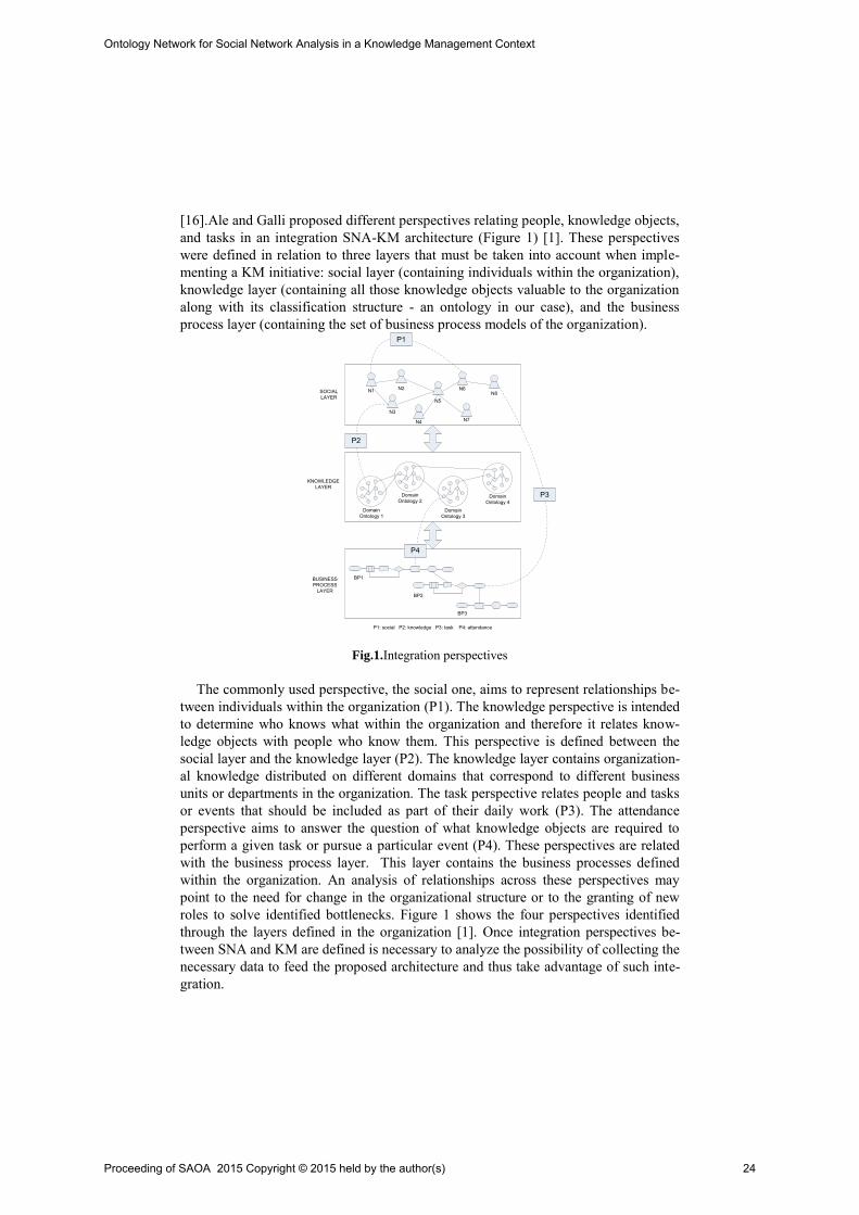
[16].Ale and Galli proposed different perspectives relating people, knowledge objects, and tasks in an integration SNA-KM architecture (Figure 1) [1]. These perspectives were defined in relation to three layers that must be taken into account when imple-menting a KM initiative: social layer (containing individuals within the organization), knowledge layer (containing all those knowledge objects valuable to the organization along with its classification structure - an ontology in our case), and the business process layer (containing the set of business process models of the organization).
SOCIALLAYER
KNOWLEDGELAYER
BUSINESSPROCESS
LAYER
N1 N2
N3
N4
N5
N6
N7
N8
DomainOntology 1
DomainOntology 2
DomainOntology 3
DomainOntology 4
BP1
BP2
BP3
P1
P2
P3
P4
P1: social P2: knowledge P3: task P4: attendance Fig.1.Integration perspectives
The commonly used perspective, the social one, aims to represent relationships be-tween individuals within the organization (P1). The knowledge perspective is intended to determine who knows what within the organization and therefore it relates know-ledge objects with people who know them. This perspective is defined between the social layer and the knowledge layer (P2). The knowledge layer contains organization-al knowledge distributed on different domains that correspond to different business units or departments in the organization. The task perspective relates people and tasks or events that should be included as part of their daily work (P3). The attendance perspective aims to answer the question of what knowledge objects are required to perform a given task or pursue a particular event (P4). These perspectives are related with the business process layer. This layer contains the business processes defined within the organization. An analysis of relationships across these perspectives may point to the need for change in the organizational structure or to the granting of new roles to solve identified bottlenecks. Figure 1 shows the four perspectives identified through the layers defined in the organization [1]. Once integration perspectives be-tween SNA and KM are defined is necessary to analyze the possibility of collecting the necessary data to feed the proposed architecture and thus take advantage of such inte-gration.
Proceeding of SAOA 2015 Copyright © 2015 held by the author(s) 24
Ontology Network for Social Network Analysis in a Knowledge Management Context
Due to the advancement of data mining techniques the main components of the social layer (nodes and relations) can be extracted and characterized [17]. A technique commonly used for node detection involves the discovery of names and references to persons within the text. There are two main approaches to this task, the first involves the search for names that are in a dictionary [18] the second applies linguistic rules or patterns to the content and sentence structure to identify potential names. These pat-terns and linguistic rules are usually built based on characteristic attributes of words such as frequency, context and position in the text [19]. For details on the recognition of named entities see Nadeau and Sekine [20]. Knowledge involved in organizational domains (knowledge layer) can be classified into three groups: knowledge commonly used throughout the organization, knowledge specifically used by a domain and knowledge shared between domains. This know-ledge classification can be properly represented by an ontology network, in which common concepts are modeled by a general ontology, domain specific concepts are modeled by domain ontologies and concepts shared between domains are modeled by relationships between concepts of domain ontologies.
4 KNOWLEDGE LAYER DESIGN
As it was said in Section 1, this work focuses on the development of the knowledge layer. To carry out the design and development of this layer the NeOn methodology has been applied, using NeOn Toolkit1. This particular methodology has been chosen due to NeOn [21] has been successfully used to build ontology networks for different domains and by people with diverse background, for example, and just to name a few, in e-employment [22], in education [23] in tourism [24] and in mobile environments [25]. NeOn can be adapted to user needs, and includes new processes and activities involved in developing ontology networks. Following this methodology, the compe-tency questions technique [26] to elicit ontology requirements was used. Enron Corpus [27] is used as information source to discover the network of domains ontologies. The Enron Corpus contains 96,107 messages from the "Sent Mail" direc-tories of all the users in the corpus. Divided across 45 files, the Enron Corpus contains 2,205,910 lines and 13,810,266 words. This corpus was selected due to it is the single corpus of "real" emails publicly available suitable for this study.
4.1 Ontology Network Scope and Formality Level
Knowledge management ensures the development and application of all types of rele-vant knowledge in a company in order to improve their ability to solve problems and contribute to the sustainability of their competitive advantages. In this context, it is crucial to identify those who are a source of valuable information and support the transformation of organizational knowledge to some structured form that can be processed. Consequently, the purpose of the ontology network proposed is to model
1http://neon-toolkit.org/wiki/Main_Page.html
Proceeding of SAOA 2015 Copyright © 2015 held by the author(s) 25
Ontology Network for Social Network Analysis in a Knowledge Management Context

semantic information concerning the knowledge objects of Enron employees from the data obtained in the Enron Corpus. In terms of scope, services provided by Enron are grouped into the following domains: Energy services, Broadband services, Risk Man-agement services and General specification. The last domain involves those concepts that are common for the three services type.
To meet the requirements of the platform proposed the ontology network is imple-mented in OWL 2. This language provides a good balance between expressivity and computational completeness.
4.2 Requirements and Intended users/uses identified
The analysis of the motivating scenarios allowed us to identify as intended users of the ontology: managers and employees that create/use knowledge objects. The analy-sis of the motivating scenarios described in [21], allowed us to identify as the main intended uses of the ontology: representation, search and retrieval of knowledge ob-jects. As non-functional requirements we can mention that the ontology has to be developed in English. Due to the lack of domain experts, competency questions were elicited from Enron Corpus. Forty competency questions grouped into four groups were defined:
Energy services Group: covers all the topics and concepts of one of the business units within Enron, whose purpose was to supply gas, electricity and related manage-ment services directly to businesses and homes.
Broadband services Group: covers all the topics and concepts of three business units within Enron: intermediation, fiber optic network and content services. Acquisi-tions business was based on the e-commerce platform Enron Online.
Risk management services Group: covers all the topics and concepts of a business unit that was used by both Enron and their customers. The purpose of this unit was managing risks to provide security and integrity of the buying and selling of products. Financial accounting and commercial prepaid were part of the service they provided.
General Group: Common themes and concepts shared with other groups. Some of the competency questions of General Domain can be seen in Table 1.
Competency Questions – General Domain
1. What are the research projects? 2. Who are the employees of Enron that participate in research projects? 3. How many employees does Enron have? 4. What are the main services provided by Enron? 5. What are the areas of knowledge generated by employees in the services? 6. How many customers have by services? 7. What are the contracts that Enron have? 8. How much annual revenue generated by the Company's services? 9. What are the Enron departments? 10. What are the most important departments by services?
Proceeding of SAOA 2015 Copyright © 2015 held by the author(s) 26
Ontology Network for Social Network Analysis in a Knowledge Management Context

11. What are the most qualified employees by departments? 12. What are the filed reports? 13. What are the Enron power plants?
14. What countries have the power plants?
Table 1. Examples of competency questions from General Domain
4.3 Terminology extraction
Competency questions were answered by performing a text mining of the Enron Cor-pus by using Automap2..Main terms were extracted from competency questions and their answers, counting frequency of their occurrence. Extracted terms were formally represented in the ontology network by means of concepts, attributes and relations.
Fig.2. Ontology Domain – General
In Figure 2 main concepts of domain General can be seen. Term General represents the ontology concept "Thing". It is related to Market, Person and Project concepts through hasMarket, hasPerson and hasProject relationships respectively. Relation-ship hasMember relates Employee and Project concepts denoting that employees are part of company projects. Concept Employee is a subclass of concept Person and inherits its properties. Relationships hasSupplier and hasSales relate the Market con-cept with Supplier and Sales concepts. Relationships hasContract and hasReport re-late Sales concept with Contract and Report concepts respectively. These relation-ships denote that sales are made through contracts and informed through reports. Relationship hasCustomer relates Contract concept to Customer. The Customer con-cept is related to Person and Company concepts through subClassOf and belongTo
relationships respectively. Relationship subClassOf denotes that customer is a sub-class of person and inherits its properties and relationship belongTo denotes that a customer belongs to a company.
2http://www.casos.cs.cmu.edu/projects/automap/
Proceeding of SAOA 2015 Copyright © 2015 held by the author(s) 27
Ontology Network for Social Network Analysis in a Knowledge Management Context
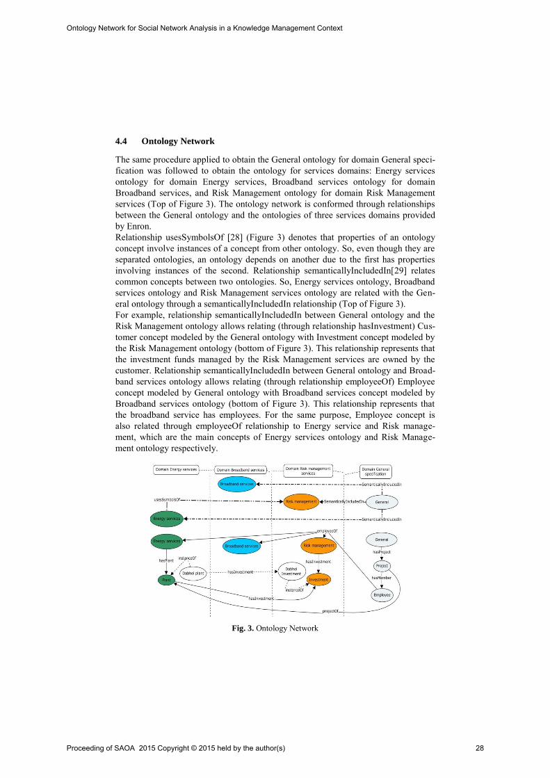
4.4 Ontology Network
The same procedure applied to obtain the General ontology for domain General speci-fication was followed to obtain the ontology for services domains: Energy services ontology for domain Energy services, Broadband services ontology for domain Broadband services, and Risk Management ontology for domain Risk Management services (Top of Figure 3). The ontology network is conformed through relationships between the General ontology and the ontologies of three services domains provided by Enron. Relationship usesSymbolsOf [28] (Figure 3) denotes that properties of an ontology concept involve instances of a concept from other ontology. So, even though they are separated ontologies, an ontology depends on another due to the first has properties involving instances of the second. Relationship semanticallyIncludedIn[29] relates common concepts between two ontologies. So, Energy services ontology, Broadband services ontology and Risk Management services ontology are related with the Gen-eral ontology through a semanticallyIncludedIn relationship (Top of Figure 3). For example, relationship semanticallyIncludedIn between General ontology and the Risk Management ontology allows relating (through relationship hasInvestment) Cus-tomer concept modeled by the General ontology with Investment concept modeled by the Risk Management ontology (bottom of Figure 3). This relationship represents that the investment funds managed by the Risk Management services are owned by the customer. Relationship semanticallyIncludedIn between General ontology and Broad-band services ontology allows relating (through relationship employeeOf) Employee concept modeled by General ontology with Broadband services concept modeled by Broadband services ontology (bottom of Figure 3). This relationship represents that the broadband service has employees. For the same purpose, Employee concept is also related through employeeOf relationship to Energy service and Risk manage-ment, which are the main concepts of Energy services ontology and Risk Manage-ment ontology respectively.
Fig. 3. Ontology Network
Proceeding of SAOA 2015 Copyright © 2015 held by the author(s) 28
Ontology Network for Social Network Analysis in a Knowledge Management Context
Relationship semanticallyIncludedIn between General ontology and Energy services ontology allows relating (through relationship projectOf) Project concept modeled by General ontology with Plant concept modeled by Energy services ontology (bottom of Figure 3). This relationship represents those projects that involve Enron production plants. Relationship usesSymbolsOf between Risk Management ontology and Energy services ontology allows relating (through relationship hasInvestment) Plant concept modeled by Energy services ontology with Investment concept modeled by Risk Management ontology. This relationship represents that the instances of Plant concept have Investment among their properties.
5 CONCLUSIONS AND FUTURE WORK
In this paper, the topic of ontology network design to feed the proposed methods for SNA-KM integration architecture was addressed. The main focus was to develop an knowledge representation model to support the knowledge layer defined in the inte-gration architecture of enterprise knowledge management and social network analysis techniques. The ontology network proposed constitutes a representation layer of orga-nizational knowledge that provides a homogeneous view of organizational knowledge objects that are naturally heterogeneous.
The modeling of knowledge objects enables to define some perspectives of the proposed architecture. Specifically, those perspectives that relate knowledge objects with people and knowledge objects with tasks.
As future work, there is the testing of techniques for knowledge objects classifica-tion using the ontology network defined with the appropriate search and retrieval strategies of these objects and the modeling of the other two architecture layers.
REFERENCES
[1] M. Ale and M.R. Galli, “Integration Perspectives of Organizational Knowledge Management and Social Network Analysis”, Proceedings of XXXIX Latin American Computing Conference, CLEI 2013, pp. 414-421.
[2] J. Scott and P. Carrington, Eds., The SAGE Handbook of Social Network Analysis [Hardcover]. SAGE Publications Ltd, 2011, p. 640.
[3] P. Drucker, “What business can learn from nonprofits,” Harvard business review, vol. 67, no. 4, pp. 88–93, 1989.
[4] C. M. Savage, 5th generation management: integrating enterprises through human networking. Newton, MA, USA: Digital Press, 1990, p. 267.
[5] R. M. Kanter, Evolve!: Succeeding in the Digital Culture of Tomorrow. Harvard Business Press, 2001, p. 352.
[6] Y.-M. Li, T.-F. Liao, and C.-Y. Lai, “A social recommender mechanism for improving knowledge sharing in online forums,” Information Processing & Management, vol. 48, no. 5, pp. 978–994, Sep. 2012.
[7] F. Ricci, L. Rokach, and B. Shapira, Eds., Introduction to recommender systems handbook. Springer US, 2011, pp. 1–35.
[8] P. Hildreth and C. Kimble, Knowledge networks: Innovation through communities of practice. IGI Global, 2004, p. 354.
Proceeding of SAOA 2015 Copyright © 2015 held by the author(s) 29
Ontology Network for Social Network Analysis in a Knowledge Management Context
[9] C. Haythornthwaite, “Social network analysis: An approach and technique for the study of information exchange,” Library & Information Science Research, vol. 18, no. 4, pp. 323–342, Sep. 1996.
[10] R. Gulati, “Does familiarity breed trust? The implications of repeated ties for contractual choice in alliances,” Academy of management journal, vol. 38, no. 1, pp. 85–112, 1995.
[11] I. Nonaka and H. Takeuchi, The Knowledge-Creating Company: How Japanese Companies Create the Dynamics of Innovation. Oxford University Press, 1995, p. 304.
[12] M. A. McFadyen, M. Semadeni, and A. A. Cannella, “Value of strong ties to disconnected others: Examining knowledge creation in biomedicine,” Organization science, vol. 20, no. 3, pp. 552–564, 2009.
[13] D. Klimkeit, “Networks , Forms of Exchange and Motivations. Insights from Social Anthropology for the Issue of Knowledge Sharing,” in Professional Knowledge Management, 2005, pp. 392–397.
[14] A. Gruzd and C. Haythornthwaite, “Networking online: cybercommunities,” in The SAGE Handbook of Social Network Analysis, J. Scott and P. J. Carrington, Eds. SAGE Publications Ltd, 2011, pp. 167–179.
[15] D. Enemark, M. McCubbins, and N. Weller, “Knowledge and networks: An experimental test of how network knowledge affects coordination,” Soc. Networks, 2014.
[16] R. Cross, A. Parker, and S. Borgatti, “A bird’s-eye view: Using social network analysis to improve knowledge creation and sharing,” 2002. [Online]. Available: http://www.workinfo.org/index.php/articles/item/709-a-bird-s-eye-view-using-social-network-analysis-to-improve-knowledge-creation-and-sharing. [Accessed: 25-Apr-2014].
[17] A. Gruzd and C. Haythornthwaite, “Networking online: cybercommunities,” in Handbook of Social Network Analysis., J. Scott and P. Carrington, Eds. SAGE Publications Ltd, 2011, pp. 168–179.
[18] M. Harada, S. Sato, and K. Kazama, “Finding authoritative people from the web,” Proc. 4th ACM/IEEE-CS Jt. Conf. Digit. Libr., pp. 306–313, 2004.
[19] D. Nadeau, P. Turney, and S. Matwin, “Unsupervised named-entity recognition: Generating gazetteers and resolving ambiguity,” in Lecture Notes in Computer Science: Advances in Artificial Intelligence, J. G. Carbonell and J. Siekmann, Eds. SAGE Publications, Inc; 2nd edition, 2006, pp. 266–277.
[20] D. Nadeau and S. Sekine, “A survey of named entity recognition and classification,” Lingvisticae Investig., vol. 1, no. 30, pp. 3–26, 2007.
[21] M. C. Suárez-Figueroa, A. Gómez-Pérez, and M. Fernández-López, "The NeOn Methodology for Ontology Engineering", Book Chapter in Ontology Engineering in a Networked World, 2012, Publisher: Springer Berlin Heidelberg, pp. 9-34.
[22] Villazón-Terrazas B, Ramírez J, Suárez-Figueroa MC, Gómez-Pérez A (2011) A network of ontology networks for building e-employment advanced systems. Expert Syst Appl 38(11):13612–13624.
[23] Clemente J, Ramírez A, de Antonio A (2011) A proposal for student modeling based on ontologies and diagnosis rules. Expert Syst Appl 38(7):8066–8078.
[24] Lamsfus C, Alzua-Sorzabal A, Martin D, Salvador Z, Usandizaga A (2009) Human-centric ontology-based context modelling in tourism. In: Proceedings of KEOD 2009 Proceedings of the International Conference onKnowledge Engineering and Ontology Development, Funchal - Madeira, Portugal, October 6–8, 2009. INSTICC Press 2009, ISBN 978-989-674-012-2, pp 424–434.
[25] Poveda-Villalón M, Suárez-Figueroa MC, García-Castro R, Gómez-Pérez A (2010) A context ontology for mobile environments. In: Workshop on Context, Information and Ontologies (CIAO 2010) co-located with EKAW 2010, Lisbon.
[26] M. Gruninger, M. S. Fox. The role of competency question in enterprise engineering. In Proceedings of the IFIP WG5.7 Workshop on Benchmarking - Theory and Practice, Trondheim, Norway, 1994.
[27] The Enron Sent Corpus v1.0. Compiled by Will Styler at the University of Colorado. Available at http://www.cs.cmu.edu/~enron/.
[28] Dıaz, A., Motz, R., & Rohrer, E. (2011). Making ontology relationships explicit in a ontology network. In V Alberto Mendelzon International Workshop on Foundations of Data Management (AWM 2011), Santiago, Chile.
[29] (C. Allocca, M. D’Aquin, and E. Motta. DOOR - Towards a Formalization of Ontology Relations. In Jan L. G. Dietz, editor, KEOD, pages 13–20. INSTICC Press, 2009.).
Proceeding of SAOA 2015 Copyright © 2015 held by the author(s) 30
Ontology Network for Social Network Analysis in a Knowledge Management Context

SCK: Una ontología para evaluar la performance de una cadena de suministro en ambientes de simulación
distribuida
Juan L. Sarli1, Ma. de los Milagros Gutiérrez2
1 INGAR, Instituto de Diseño y Desarrollo CONICET – UTN, Santa Fe, Argentina [email protected]
2 CIDISI, Centro de Investigación y Desarrollo de Ingeniería en Sistemas de Información UTN, Santa Fe, Argentina
Abstract. Utilizar simulación distribuida para analizar cadenas de suminis-tro favorece el reuso de simuladores independientes pertenecientes a los miem-bros de la cadena minimizando el costo de desarrollo de un simulador. Sin em-bargo, componer estos simuladores es un problema a resolver. Existen diferen-tes niveles de composición de simuladores: sintáctico, semántico y pragmático. Para atacar este problema es necesario expresar el dominio y el conocimiento de los componentes de una manera no ambigua y estandarizada. En este contex-to, las ontologías son útiles ya que proveen una forma de representar el conoci-miento a través de taxonomías de conceptos, axiomas, reglas y relaciones entre estos. Se presenta la ontología SCK como parte de una red de ontologías, para representar el conocimiento semántico de una cadena de suministro basada en los conceptos principales del modelo SCOR con el fin de proveer una herra-mienta adecuada para evaluar cadenas de suministro en el contexto de simula-ción distribuida.
Keywords: Simulación distribuida, HLA, cadena de suministro, modelo SCOR, ontologías.
1 Introducción
En los últimos quince años la comunidad de modelado y simulación ha demostrado un creciente interés hacia la construcción de modelos de simulación a partir de la composición de modelos existentes [1-4]. Este esquema es sumamente conveniente ya que promueve el reuso de los simuladores utilizados por cada uno de los participantes, minimizando el tiempo y la inversión de construcción de la simulación, y además, preserva tanto la autonomía local como la privacidad de los datos [5]. Estas características hacen adecuada la utilización de este enfoque para simular cadenas de suministro (CS). Una CS es una de las redes organizacionales más populares donde sus miembros realizan alianzas para alcanzar metas más importantes de las que obtendrían de forma aislada [6], [7]. El éxito de una CS depende de la coordinación
Proceeding of SAOA 2015 Copyright © 2015 held by the author(s) 31
de las actividades de los participantes para hacer eficiente el flujo de materiales, de información y financiero. En este contexto, la simulación de una CS adquiere un rol fundamental.
La construcción de modelos de simulación a partir de otros modelos, denominados “bloques” reutilizables, trae aparejado el problema de la composición de simuladores. Dicho problema posee diferentes niveles, los cuales son: sintáctico, semántico y pragmático. La composición sintáctica se refiere a la conexión y comunicación entre componentes. La composición semántica determina si el modelo de simulación, armado a partir de los bloques, es semánticamente válido. Este tipo de composición determina si los bloques que integran el sistema de simulación están compuestos de una manera significativa y dicha composición es válida [8], [9]. Para componer sistemas de simulación correctamente y alcanzar una interoperabilidad válida la alineación y comprensión consistente debe ser alcanzada a nivel de un modelo conceptual [10]. Finalmente, la composición pragmática establece si los componentes son conscientes del contexto de simulación en el que se están ejecutando [3], y de ser este el caso, los componentes conocen cual es el uso que se le va a dar a los datos [11].
HLA (High Level Architecture) [12] es una propuesta ampliamente usada para construir simuladores a partir de la composición de simuladores independientes que interactúan a través de una interface común, para ello propone un esquema de federaciones y federados. Esta propuesta es una solución a la composición sintáctica de simuladores ya que estandariza el protocolo de comunicación y el formato del modelo de objetos que debe ser utilizado por los componentes. Para dar soporte a la composición semántica de simuladores en este esquema es necesario expresar el dominio de los componentes de una forma no ambigua, donde la semántica de los conceptos sea representada en forma explícita.
En este contexto, las ontologías son utilizadas para organizar la representación del conocimiento y capturar objetos de información en un dominio particular [13]. Continuando con esta investigación, en [5] se presenta la red de ontologías SCFHLA (Supply Chain Federation HLA) como propuesta para dar soporte a la composición semántica de simuladores en el contexto de una federación de CS. Este modelo conceptual considera cuatro dominios específicos: (i) El dominio de las CS, el cual es modelado por la ontología SCOnto (Supply Chain Ontology) [14] basada en el modelo SCOR (Supply Chain Operation Reference) [15], (ii) el dominio de federaciones modelado por la ontología FEDOnto (Federation Ontology), (iii) el dominio del modelo de objetos BOMOnto (Base Object Model Ontology) y (iv) el dominio de los modelos de empresa EMOnto (Enterprise Model Ontology).
Sin embargo, esta propuesta es una definición de alto nivel que muestra una aproximación a la resolución del problema. A su vez, SCOnto está basada en una versión previa del modelo SCOR y algunos de sus conceptos deben ser actualizados.
Por lo tanto para superar las debilidades señaladas, este trabajo propone incluir la ontología SCK (Supply Chain Knowledge) en la red SCFHLA de manera que dicha red (con la ontología SCK añadida) sea la base conceptual de una herramienta que permita la generación semiautomática de un modelo de objetos conceptual para una instancia dada de una federación HLA. El objetivo principal de la ontología propuesta
Proceeding of SAOA 2015 Copyright © 2015 held by the author(s) 32
SCK: Una ontología para evaluar la performance de una cadena de suministro en ambientes de simulación distribuida
es representar el conocimiento semántico de una CS usando la versión actual del modelo SCOR y relacionarlo con los conceptos básicos de una federación HLA de simulación para evaluar la performance de una CS.
El resto del trabajo se organiza de la siguiente manera. En la siguiente sección se presentan los conceptos preliminares para entender el trabajo tales como el modelo SCOR y el estándar HLA. Luego se presenta la ontología SCK y su integración a la red SCFHLA. Seguido se desarrolla un ejemplo donde se muestra la utilización de la ontología propuesta. Finalmente el trabajo se concluye y los trabajos futuros son presentados.
2 Conceptos Preliminares
2.1 Modelo SCOR
Este modelo fue desarrollado por la organización Supply Chain Council, y presenta los conceptos más importantes para modelar una CS. Además, permite comparar y evaluar el rendimiento de la CS como un todo y de sus actividades particulares. Dado que SCOR es un modelo conceptual, provee una terminología común y facilita el entendimiento a través de la CS. Este modelo ayuda a analizar, medir, fijar objetivos de performance, determinar oportunidades de mejora, identificar mejores prácticas y priorizar proyectos en la gestión de la CS.
SCOR [15] está organizado alrededor de los seis procesos de gestión básicos: Plan, Source, Make, Deliver, Return y Enable. También, define tres niveles jerárquicos de procesos los cuales son:
• Nivel 1 o Alcance•
: Define los tipos de procesos, alcance y contenido de la CS. Nivel 2 o Configuración
•
: Define las categorías de procesos y la estrategia de ope-raciones. Nivel 3 o Pasos
En todos los niveles, el modelo provee indicadores claves de rendimiento, los cua-les se dividen sistemáticamente en cinco atributos de performance: Confiabilidad, Capacidad de Respuesta, Agilidad, Costos y Gestión de Activos (Activos).
: Define los elementos de proceso y la configuración de los proce-sos individuales.
De acuerdo al modelo SCOR un atributo de rendimiento es un conjunto de métri-cas usadas para expresar una estrategia [15]. En el contexto del modelo SCOR un atributo no posee el mismo significado que en modelado conceptual. Un atributo por sí mismo no puede ser medido; es usado para determinar una dirección estratégica. Las métricas de SCOR están organizadas en una estructura jerárquica. El modelo describe métricas de nivel uno, dos y tres. Las relaciones entre estos niveles son dia-gnósticas, por ejemplo: las métricas de nivel 2 sirven como diagnóstico para las de nivel 1. Esto significa que observando el rendimiento de las métricas de nivel 2 se puede explicar las diferencias de performance, o las posibles mejoras, para las métri-cas de nivel 1. Este tipo de análisis de rendimiento de la CS se conoce como descom-posición de métricas [15].
Proceeding of SAOA 2015 Copyright © 2015 held by the author(s) 33
SCK: Una ontología para evaluar la performance de una cadena de suministro en ambientes de simulación distribuida

2.2 Estándar HLA
HLA es una arquitectura estándar para reuso, integración e interoperabilidad de simuladores. Soporta el reuso de capacidades disponibles en diferentes simuladores, y posibilita el desarrollo de simuladores complejos de manera distribuida. La arquitec-tura HLA provee un framework dentro del cual los desarrolladores de simuladores pueden estructurar y describir sus aplicaciones de simulación. En este sentido HLA propone integrar sistemas de simulación diferentes, en un sistema mayor sin necesi-dad de reescribir algún componente o comenzar a crear desde cero el modelo de ma-yor nivel y su respectivo simulador. Cuando un simulador se implementa para que cumpla las especificaciones HLA se lo llama Federado. Luego, los federados se unen en federaciones las que se refieren a la simulación del sistema complejo formado. La definición de HLA abarca tres componentes esenciales (Figura 1) [12]:
• Reglas
•
: Es un conjunto de ítems que definen las responsabilidades y relaciones entre los componentes de una federación HLA. Deben ser seguidas por los federa-dos y las federaciones que quieran ajustarse al estándar. Seguir estas reglas asegura una interacción correcta entre los simuladores en una federación. Especificación de la Interfaz
•
: Define la interfaz funcional entre federados HLA y la infraestructura de ejecución (RTI - Run-Time Infrastructure) de HLA. Se detallan los servicios que debe prestar el RTI, e identifica las funciones callback que debe proveer cada federado. El RTI ofrece una librería de programación y una interfaz de programación de aplicaciones (API – Application Program Interface) compati-ble con la especificación de la interfaz. Patrón de Modelo de Objeto (OMT)
Modelo de Objetos de la Federación (FOM - Federation Object Model): Descri-be los objetos, los atributos y las interacciones de la federación completa.
: Provee un framework común para la comuni-cación entre los federados. OMT consta de los siguientes documentos:
Modelo de Objetos de la Simulación (SOM - Simulation Object Model): Des-cribe los objetos, atributos e interacciones usados por un federado.
Modelo de Objetos de Gestión (MOM - Management Object Model): Provee fa-cilidades para acceder a información operativa del RTI en tiempo de ejecución. El MOM debe ser definido utilizando objetos, interacciones y constructores de la arquitectura de comunicación de HLA.
Fig. 1. Componentes HLA
Proceeding of SAOA 2015 Copyright © 2015 held by the author(s) 34
SCK: Una ontología para evaluar la performance de una cadena de suministro en ambientes de simulación distribuida
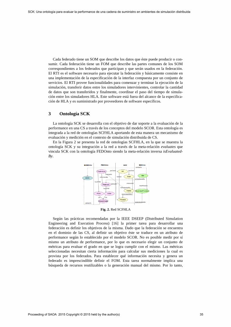
Cada federado tiene un SOM que describe los datos que éste puede producir o con-sumir. Cada federación tiene un FOM que describe las partes comunes de los SOM correspondientes a los federados que participan y que serán usados en la federación. El RTI es el software necesario para ejecutar la federación y básicamente consiste en una implementación de la especificación de la interfaz compuesta por un conjunto de servicios. El RTI provee funcionalidades para comenzar y terminar la ejecución de la simulación, transferir datos entre los simuladores intervinientes, controlar la cantidad de datos que son transferidos y finalmente, coordinar el paso del tiempo de simula-ción entre los simuladores HLA. Este software está fuera del alcance de la especifica-ción de HLA y es suministrado por proveedores de software específicos.
3 Ontología SCK
La ontología SCK se desarrolla con el objetivo de dar soporte a la evaluación de la performance en una CS a través de los conceptos del modelo SCOR. Esta ontología es integrada a la red de ontologías SCFHLA aportando de esta manera un mecanismo de evaluación y medición en el contexto de simulación distribuida de CS.
En la Figura 2 se presenta la red de ontologías SCFHLA, en la que se muestra la ontología SCK y su integración a la red a través de la meta-relación evaluates que vincula SCK con la ontología FEDOnto siendo la meta-relación inversa isEvaluated-By.
Fig. 2. Red SCFHLA
Según las prácticas recomendadas por la IEEE DSEEP (Distributed Simulation Engineering and Execution Process) [16] la primer tarea para desarrollar una federación es definir los objetivos de la misma. Dado que la federación se encuentra en el dominio de las CS, al definir un objetivo éste se traduce en un atributo de performance según lo establecido por el modelo SCOR. No es posible medir por sí mismo un atributo de performance, por lo que es necesario elegir un conjunto de métricas para evaluar el grado en que se logra cumplir con el mismo. Las métricas seleccionadas necesitan cierta información para calcular sus mediciones la cual es provista por los federados. Para establecer qué información necesita y genera un federado es imprescindible definir el FOM. Esta tarea normalmente implica una búsqueda de recursos reutilizables o la generación manual del mismo. Por lo tanto,
Proceeding of SAOA 2015 Copyright © 2015 held by the author(s) 35
SCK: Una ontología para evaluar la performance de una cadena de suministro en ambientes de simulación distribuida
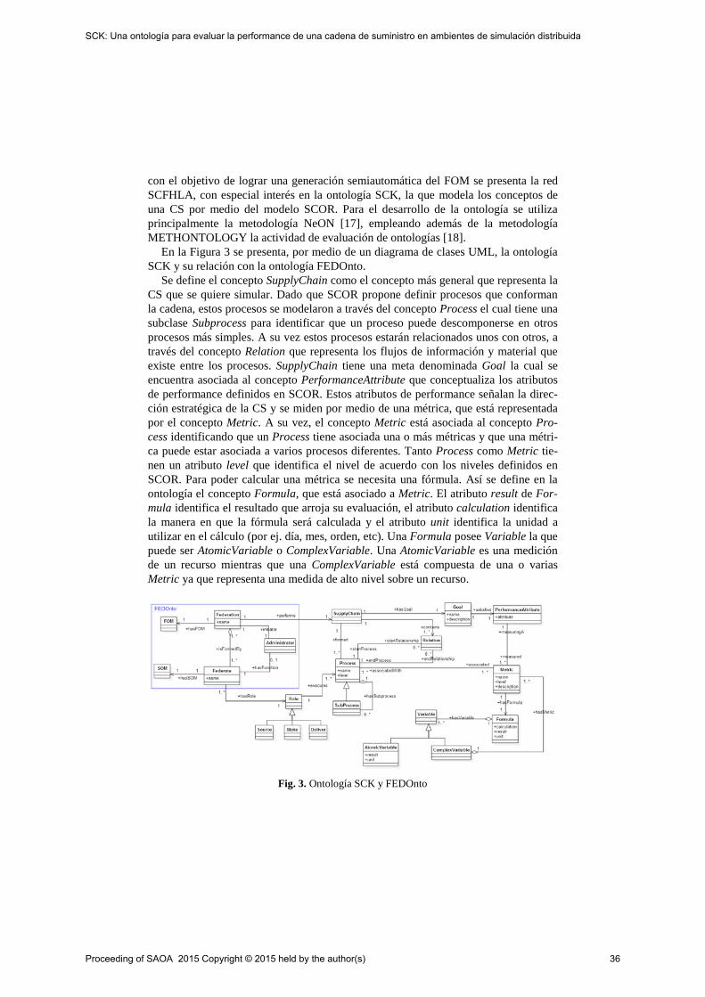
con el objetivo de lograr una generación semiautomática del FOM se presenta la red SCFHLA, con especial interés en la ontología SCK, la que modela los conceptos de una CS por medio del modelo SCOR. Para el desarrollo de la ontología se utiliza principalmente la metodología NeON [17], empleando además de la metodología METHONTOLOGY la actividad de evaluación de ontologías [18].
En la Figura 3 se presenta, por medio de un diagrama de clases UML, la ontología SCK y su relación con la ontología FEDOnto.
Se define el concepto SupplyChain como el concepto más general que representa la CS que se quiere simular. Dado que SCOR propone definir procesos que conforman la cadena, estos procesos se modelaron a través del concepto Process el cual tiene una subclase Subprocess para identificar que un proceso puede descomponerse en otros procesos más simples. A su vez estos procesos estarán relacionados unos con otros, a través del concepto Relation que representa los flujos de información y material que existe entre los procesos. SupplyChain tiene una meta denominada Goal la cual se encuentra asociada al concepto PerformanceAttribute que conceptualiza los atributos de performance definidos en SCOR. Estos atributos de performance señalan la direc-ción estratégica de la CS y se miden por medio de una métrica, que está representada por el concepto Metric. A su vez, el concepto Metric está asociada al concepto Pro-cess identificando que un Process tiene asociada una o más métricas y que una métri-ca puede estar asociada a varios procesos diferentes. Tanto Process como Metric tie-nen un atributo level que identifica el nivel de acuerdo con los niveles definidos en SCOR. Para poder calcular una métrica se necesita una fórmula. Así se define en la ontología el concepto Formula, que está asociado a Metric. El atributo result de For-mula identifica el resultado que arroja su evaluación, el atributo calculation identifica la manera en que la fórmula será calculada y el atributo unit identifica la unidad a utilizar en el cálculo (por ej. día, mes, orden, etc). Una Formula posee Variable la que puede ser AtomicVariable o ComplexVariable. Una AtomicVariable es una medición de un recurso mientras que una ComplexVariable está compuesta de una o varias Metric ya que representa una medida de alto nivel sobre un recurso.
Fig. 3. Ontología SCK y FEDOnto
Proceeding of SAOA 2015 Copyright © 2015 held by the author(s) 36
SCK: Una ontología para evaluar la performance de una cadena de suministro en ambientes de simulación distribuida

En la ontología FEDOnto se representan los conceptos relacionados con la simula-ción distribuida de acuerdo al modelo HLA. Así se representa la federación con el concepto Federation y el federado se representa por el concepto Federate. Para este contexto particular una federación representa la simulación de una CS. Para su repre-sentación se definió la relación performs que relaciona el concepto Federation con SupplyChain. Además se identifica que un federado participante de una federación debe tener un rol asociado para identificar el proceso de la CS que dicho federado modela. Para su representación, se definieron los conceptos Role que identifica el rol y tres subclases del mismo Source, Make o Deliver. A su vez, se define la relación executes entre Role y Process para indicar que un federado que juega ese rol ejecuta ese proceso de la cadena.
La ontología SCK se implementó utilizando la herramienta Protégé1 versión 4.3. Para transformar el modelo conceptual de la Figura 3 en la ontología se aplicaron los siguientes criterios: (a) Las clases se transformaron en clases OWL2
4 Definición de una Federación de CS
(Web Ontology Lenguage). (b) Las relaciones se mapearon como Object Properties. (c) Los atributos se tradujeron en Data Properties.
En esta sección se presenta un ejemplo de uso de la ontología SCK. Considere una CS cuya meta es: Cumplir de forma perfecta con el 80% de las entregas de autos desde la fábrica hacia el concesionario durante el período de un año. Esta CS se crea como una instancia de SupplyChain denominada Automóvil CS en la ontología. Su meta se define como instancia de Goal cuyo nombre es Objetivo CS y que contiene en el atributo description el objetivo de la CS. Según el modelo SCOR, esta meta se traduce en el atributo de performance “Confiabilidad” y es medido por la métrica de nivel uno “Cumplimiento Perfecto de Orden”. Este atributo de performance se deno-mina Atributo CS y es una instancia de PerformanceAttribute cuya propiedad attribu-te contiene el atributo “Confiabilidad”. La métrica que lo releva se nombra como Ordenes Perfectas y es una instancia de Metric que posee el atributo level en uno y la propiedad name con el nombre de dicha métrica. El cumplimiento perfecto de orden posee una fórmula que se crea como instancia de Formula denominada Formula Or-denes Perfectas. Además, esta fórmula posee en el atributo calculation como calcular-se y en el atributo unit su unidad de medida. Para el cálculo de las órdenes perfectas se necesitan dos variables: total de órdenes y total de órdenes perfectas. La primera se define en el modelo como instancia de AtomicVariable con el mismo nombre y con la unidad orden. La segunda se denomina como Total Ordenes Perfectas y es instancia de ComplexVariable. Esta variable compleja se compone de cuatro métricas de nivel dos las cuales son: 1) Ordenes Entregadas Completas, 2) Entrega en Fecha, 3) Docu-mentación Precisa y 4) Condición Perfecta. Cada una de ellas se crea como instancia de Metric. La métrica 1) posee la formula denominada Formula Orden Completa que es instancia de Formula. Dicha fórmula tiene las AtomicVariable Ordenes Entregadas
1 http://protege.stanford.edu/ 2 http://semanticweb.org/wiki/OWL_2
Proceeding of SAOA 2015 Copyright © 2015 held by the author(s) 37
SCK: Una ontología para evaluar la performance de una cadena de suministro en ambientes de simulación distribuida
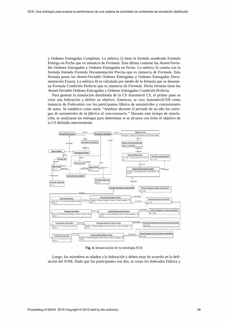
y Ordenes Entregadas Completas. La métrica 2) tiene la formula nombrada Formula Entrega en Fecha que es instancia de Formula. Esta última contiene las AtomicVaria-ble Ordenes Entregadas y Ordenes Entregadas en Fecha. La métrica 3) cuenta con la formula llamada Formula Documentación Precisa que es instancia de Formula. Esta fórmula posee las AtomicVariable Ordenes Entregadas y Ordenes Entregadas Docu-mentación Exacta. La métrica 4) es calculada por medio de la fórmula que se denomi-na Formula Condición Perfecta que es instancia de Formula. Dicha fórmula tiene las AtomicVariable Ordenes Entregadas y Ordenes Entregadas Condición Perfecta.
Para generar la simulación distribuida de la CS Automóvil CS, el primer paso es crear una federación y definir su objetivo. Entonces, se crea AutomóvilCSH como instancia de Federation con los participantes fábrica de automóviles y concesionario de autos. Se establece como meta: “Analizar durante el período de un año las entre-gas de automóviles de la fábrica al concesionario.” Durante este tiempo de simula-ción, se analizaran las entregas para determinar si se alcanza con éxito el objetivo de la CS definido anteriormente.
Fig. 4. Instanciación de la ontología SCK
Luego, los miembros se añaden a la federación y deben estar de acuerdo en la defi-nición del FOM. Dado que los participantes son dos, se crean los federados Fábrica y
Proceeding of SAOA 2015 Copyright © 2015 held by the author(s) 38
SCK: Una ontología para evaluar la performance de una cadena de suministro en ambientes de simulación distribuida

Concesionario como instancias de Federate. Se asigna el Rol Make a la fábrica por-que transforma la materia prima en los autos, en tanto que, se establece el Rol Source al concesionario porque son de interés las interacciones que tiene con la fábrica para obtener los autos. Ambos roles se crean como instancias de Role. La Fábrica por me-dio del Rol Make tiene asociado un proceso de producción para poder construir los autos. Este proceso se denomina Make (instancia de Process) y posee un subproceso Para Stock (instancia de Subprocess). El Concesionario por medio del Rol Source cuenta con un proceso para solicitar el envío de autos. Este proceso se nombra Source (instancia de Process) y cuenta con un subproceso Por Pedido (instancia de Subpro-cess). La relación entre el proceso Source y Make se denomina Solicitar Mercadería y se crea como instancia de Relation. En la Figura 4 se muestran los conceptos instan-ciados para este ejemplo.
5 Conclusión
Este trabajo ha presentado la ontología SCK para dar soporte a la evaluación de la performance de una CS mediante los conceptos del modelo SCOR. Esta ontología se ha integrado a la red de ontologías SCFHLA, permitiendo de este modo, evaluar y medir una simulación distribuida de CS. Como trabajo futuro se pretende avanzar en nuevos conceptos, relaciones, propiedades, axiomas y reglas para representar con un mayor nivel de detalle el dominio. Algunas de las propiedades que se pueden añadir al modelo son: identificador de procesos, métricas y de tipos de procesos. Este último puede ser utilizado para definir reglas lógicas que validen la composición proceso subproceso. Por lo tanto, es posible validar que un proceso este compuesto solo de subprocesos del mismo tipo.
Dada la modularidad de la red de ontologías, se está trabajando en implementar una nueva ontología para el dominio de federaciones e integrarla a la red, para lograr una representación más detallada del dominio. A su vez, la red SCFHLA con la onto-logía SCK integrada sirve de base para el desarrollo de una herramienta para definir una federación de forma colaborativa y que siga los pasos descriptos en DSEEP.
Referencias
[1] P. L. Gustavson and L. M. Root, “Object model use cases: a mechanism for capturing requirements and supporting BOM reuse,” Spring Simulation Interoperability Workshop, Mar. 1999.
[2] S. Kasputis and H. C. Ng, “Composable simulations,” in Simulation Conference, 2000. Proceedings. Winter, 2000, vol. 2, pp. 1577–1584 vol.2.
[3] A. Tolk, “What Comes After the Semantic Web - PADS Implications for the Dynamic Web,” in 20th Workshop on Principles of Advanced and Distributed Simulation, 2006. PADS 2006, Beach Road, Singapore, 2006, pp. 55–55.
[4] A. Verbraeck, “Component-based distributed simulations: the way forward?,” in 18th Workshop on Parallel and Distributed Simulation, 2004. PADS 2004, Kufstein, Austria, 2004, pp. 141–148.
Proceeding of SAOA 2015 Copyright © 2015 held by the author(s) 39
SCK: Una ontología para evaluar la performance de una cadena de suministro en ambientes de simulación distribuida

[5] M. Milagros Gutiérrez and Horacio Leone, “Composability Model In A Distributed Simu-lation Environment For Supply Chain,” presented at the 42° JAIIO Simposio Argentino de Informática Industrial (SII), Córdoba, Argentina, 2013, pp. 142–153.
[6] W. W. C. Chung, A. Y. K. Yam, and M. F. S. Chan, “Networked enterprise: A new busi-ness model for global sourcing,” International Journal of Production Economics, vol. 87, no. 3, pp. 267–280, Feb. 2004.
[7] J. Arrazola, “Towards a new model: the globally integrated enterprise,” Universia Busi-ness Review, vol. 14, pp. 108–118, May 2007.
[8] E. W. Weisel, M. D. Petty, and R. Mielke, “Validity of models and classes of models in semantic composability,” in Proceedings of the Fall Simulation Interoperability Work-shop, 2003.
[9] M. D. Petty, E. W. Weisel, and R. Mielke, “Overview of a Theory of Composability,” presented at the Virginia Modeling Analysis & Simulation Center, 2004.
[10] M. A. Hofmann, “Challenges of Model Interoperation in Military Simulations,” SIMULATION, vol. 80, no. 12, pp. 659–667, Dec. 2004.
[11] B. P. Zeigler and P. E. Hammonds, Modeling & Simulation-Based Data Engineering: Introducing Pragmatics into Ontologies for Net-Centric Information Exchange, 1 edition. Burlington, MA: Elsevier Academic Press, 2007.
[12] Institute of Electrical and Electronics Engineers and IEEE-SA Standards Board, IEEE standard for modeling and simulation (M & S) high level architecture (HLA) framework and rules. New York: Institute of Electrical and Electronics Engineers, 2010.
[13] Asunción Gómez-Pérez, Mariano Fernández-López, and Oscar Corcho, Ontological Engi-neering. London: Springer-Verlag, 2004.
[14] A. C. Böhm, H. P. Leone, and G. P. Henning, “A Supply Chain Ontology Conceptualiza-tion with Focus on Performance Evaluation,” in Proceedings of the Tenth International Conference on Enterprise Information Systems, Portugal, 2008, vol. ISAS-2, pp. 402–409.
[15] Supply Chain Council, SCOR supply chain operations reference model. The Supply Chain Council, 2012.
[16] Institute of Electrical and Electronics Engineers and IEEE-SA Standards Board, IEEE recommended practice for distributed simulation engineering and execution process (DSEEP). New York: Institute of Electrical and Electronics Engineers, 2011.
[17] M. C. Suárez-Figueroa, A. Gómez-Pérez, and M. Fernández-López, “The NeOn Method-ology for Ontology Engineering,” in Ontology Engineering in a Networked World, M. C. Suárez-Figueroa, A. Gómez-Pérez, E. Motta, and A. Gangemi, Eds. Springer Berlin Hei-delberg, 2012, pp. 9–34.
[18] Karin Koogan Breitman, Marco Antonio Casanova, and Walter Truszkowski, “Semantic Web: Concepts, Technologies, and Applications,” Computer, vol. 40, no. 7, pp. 84–84, Jul. 2007.
Proceeding of SAOA 2015 Copyright © 2015 held by the author(s) 40
SCK: Una ontología para evaluar la performance de una cadena de suministro en ambientes de simulación distribuida

Ontología para la gestión unificada de variantes y
versiones de productos
Sonzini María Soledad1,2, Vegetti Marcela1
1 INGAR, Instituto de Desarrollo y Diseño, Avellaneda 3657, Santa Fe, Arg. 2 Universidad Nacional de La Rioja, Luis M. de la Fuente S/N, La Rioja, Arg.
1ssonzini, [email protected]
Resumen. El objetivo de este trabajo es presentar una ontología para gestionar
la variación temporal de una familia de productos a través de versiones. La
propuesta permite identificar los puntos variantes, la causa, el tiempo de validez
y el control de la propagación/ impacto de los cambios. Es una ontología
genérica que puede ser integrada con distintos modelos de representación de
variantes de productos. A fin de validar la propuesta, se muestra la integración
de la ontología de versiones propuestas con la ontología PRONTO (PRoduct
ONTOlogy) [1] para la gestión de variantes de familias de productos.
Palabras Claves: Variabilidad, Ontología, Versiones, Familia de productos.
1 Introducción
La importancia de gestionar la información de los productos en todas las fases de su ciclo de vida, está en la ocurrencia de un evento de cambios en una determinada
etapa, el cual podría propagarse y afectar la consistencia e integridad de la
información en otras etapas. Pohl y colab. en [2], sostienen que es fundamental hacer
una distinción entre variabilidad en el tiempo y variabilidad en el espacio. La primera
de ellas se define como “la existencia de diferentes versiones de un producto que es
válido en diferentes tiempos”, denotando su evolución. Por el contrario, la
variabilidad en el espacio se define como “la existencia de un producto en diferentes
formas en un mismo tiempo”. Esta dimensión abarca de manera simultánea el uso de
diferentes variantes de productos que coexisten en un mismo instante de tiempo. Es
importante mencionar que los métodos utilizados actualmente en la gestión de
variabilidad espacial, no pueden aplicarse del mismo modo para la gestión de variabilidad temporal. Por esto, surge la necesidad de definir un mecanismo apropiado
para administrar los cambios en el tiempo y que pueda ser aplicado conjuntamente
con los modelos de representación de variantes existentes. De esta manera se podría
gestionar simultáneamente ambos tipos de variabilidad.
Un concepto primordial para este trabajo, es el concepto de “ontologías”, que se
han propuesto como una herramienta de integración semántica en el contexto de la
Web Semántica [3]. Una ontología es un modelo formal que representa
explícitamente el conocimiento consensuado de un dominio [4]. Es por ello, que las
Proceeding of SAOA 2015 Copyright © 2015 held by the author(s) 41

ontologías se definen para establecer un vocabulario común, sin ambigüedades entre
diferentes áreas de una misma organización o entre organizaciones diferentes. Con el fin de contar con un modelo formal para la gestión integrada de variantes y
versiones, así como un vocabulario común para la representación de los cambios que
modifican la información de productos durante su ciclo de vida, este artículo propone
una ontología, desarrollada en OWL1. La propuesta define conceptos genéricos, que
pueden ser especializados utilizando entidades de modelos de gestión de variantes
existentes. En particular, este trabajo muestra cómo el modelo propuesto puede
extenderse con conceptos de la ontología de productos PRONTO, para gestionar de
manera conjunta las variantes y las versiones. Asimismo, se presenta un conjunto de reglas, a través del lenguaje SWRL (Semantic Web Rule Language)
2, que permiten
inferir nuevo conocimiento. El artículo se organiza de la siguiente forma: la Sección 2
introduce el estado del arte acerca de la gestión de variabilidad en las dos dimensiones
de mencionadas. En la sección 3, se presenta el modelo conceptual genérico para
gestionar la variabilidad temporal, su implementación en OWL y la definición de un
conjunto de reglas de inferencia. La Sección 4 introduce un caso de estudio sencillo a
fin de validar la propuesta. Finalmente, se presentan las conclusiones y trabajos
futuros.
2 Gestión de variabilidad
En diferentes investigaciones se ha tratado el tema de la variabilidad de familias de
productos, sin embargo aún existen cuestiones sin resolver, tal como la gestión de
dependencias entre puntos de variación y variantes. Esta situación ha impulsado
algunos estudios sobre las relaciones que existen (no siempre explícitas) entre los
diferentes elementos afectados (puntos de variación) a lo largo del ciclo de vida de un
producto. Sin embargo, a pesar de que existen diversas propuestas para el manejo de
las variabilidades en el espacio y en el tiempo, no se ha encontrado soluciones que
aborden simultáneamente estas dos problemáticas.
Existe un conjunto de propuestas que se concentran en la gestión de la variabilidad
temporal de conjuntos de datos de familias de productos en el dominio de la industria
de software. Entre estas investigaciones, Männisto [5] propone una metodología para
modelar la evolución de familias de productos, incluyendo los aspectos temporales y
los mecanismos necesarios para la representación de datos. Estublier y Casallas en
[6], introducen tres dimensiones ortogonales para la gestión de versiones: histórica,
lógica y cooperativa; haciendo referencia a la evolución de un objeto en el tiempo, la
coexistencia de múltiples variantes de un objeto y la cooperación con actividades de
forma concurrente en un mismo instante de tiempo. Sjoberg [7] sostiene que para
obtener herramientas sofisticadas y poder predecir las consecuencias de los cambios,
es necesario identificar un conjunto de cuestiones, tales como: que objetos fueron
modificados, en qué instante de tiempo ocurre, cómo fueron cambiados estos objetos
1 http://www.w3.org/2007/09/OWL-Overview-es.html 2 http://www.w3.org/Submission/SWRL/
Proceeding of SAOA 2015 Copyright © 2015 held by the author(s) 42
Ontología para la gestión unificada de variantes y versiones de productos
y de qué modo se registra este acontecimiento. En cuanto a la variabilidad en el
espacio, es posible encontrar propuestas tanto en dominios relacionados con la
manufactura como en la industria del software. Por cuestiones de espacio, en este
artículo se introducirán sólo los conceptos de PRONTO [1]. PRONTO es una
ontología que permite representar datos de productos en diferentes niveles de
abstracción y en distintos dominios de la industria. Para ello define un modelo
conceptual 3 que describe dos jerarquías: la jerarquía estructural (SH - Structural
Hierarchy) para representar la información concerniente a las partes que participan en
la manufactura de un producto final, y la jerarquía de abstracción (AH - Abstraction
Hierarchy) que permite la representación de información no estructural de productos
en diferentes niveles de abstracción. La AH consta de 3 niveles: Familia (Family),
Conjunto de Variantes (VariantSet) y Producto (Product), los cuales se relacionan
entre sí mediante la asociación “memberOf”. La SH considera dos tipos de relaciones
de estructuras, que se especializan en “componentOf”, para aquellas estructuras que
relacionan al producto con sus partes componentes, y “derivateOf”, para aquellas
estructuras que enlazan al producto con sus derivados constituyentes. Es importante
aclarar que existe una SH para cada uno de los niveles de la AH y las relaciones que
la constituye se infieren a partir de las entidades y relaciones definidas de manera
explícita en PRONTO. A continuación se introducen brevemente los mismos.
Una familia representa un conjunto de productos que son similares y puede ser
simple (SFamily), o compuesta (CFamily). Esta última tiene al menos una estructura
(Structure) asociada, que puede ser: de composición (CStructure) o de
descomposición (DStructure). Los componentes de una CStructure y los derivados de
una DStructure se asocian a dicha estructura por medio de dos tipos de asociaciones:
CRelation y DRelation, respectivamente. En ambos casos, estas relaciones están
vinculadas con las cantidades de cada componente o derivado que se necesitan o
derivan de la estructura involucrada, a través de las asociaciones quantityPerUnit y
productionFactor 3. Por su parte, el nivel de conjunto de variantes modela un
subconjunto de miembros de una familia que comparten una estructura común y/o
tienen características similares. Un conjunto de variantes puede ser simple
(SVariantSet) o compuesto (CVariantSet) dependiendo de si es miembro de una
familia simple o compuesta. Un Conjunto de Variantes compuesto, se asocia a la
estructura de la familia que es compartida por todos los miembros del conjunto por
medio de la relación Has y puede definir cambios (ChangeSet) sobre la misma. Cada
uno de estos cambios, se aplican a una relación de la estructura (affectedRelation).
Existen diferentes tipos de cambios que pueden aplicarse. Su descripción está fuera
del alcance de este trabajo. Para más detalles sobre los mismos ver [1]. El nivel más bajo de la AH, el nivel de producto, representa productos que tienen
existencia física. Del mismo modo que los niveles anteriores, un producto puede ser
simple (SProduct) o compuesto (CProduct). En este último caso, la relación
ChosenProduct permite identificar los componentes o derivados concretos de un
CProduct. A fin de controlar la construcción de jerarquías estructurales válidas,
PRONTO especifica tres tipos de restricciones (FRestriction, VSRestriction,
3 Ver el modelo conceptual en el repositorio:
https://sites.google.com/site/ontoversioningrepository/pronto---product-ontology
Proceeding of SAOA 2015 Copyright © 2015 held by the author(s) 43
Ontología para la gestión unificada de variantes y versiones de productos

PRestriction) que permiten limitar las entidades que deben o no pueden estar juntas en
una misma SH en cada uno de los niveles propuestos.
3 Ontología de Versiones
En la Fig. 1 se introducen los conceptos fundamentales de la ontología de versiones
propuesta. Uno de estos es el concepto de ProductConcept, que representa el
elemento cuyas versiones se van a gestionar. El conjunto de versiones es representado
con el concepto de History. Este concepto mantiene las versiones bajo la forma de una
secuencia expresada mediante las relaciones firstVersion y previous, las cuales
denotan la evolución en el tiempo y permiten reconstruir la versión actual de un
producto a partir de las sucesivas versiones. La relación firstVersion indica la versión
inicial, y cada versión (excepto la primera), es relacionada con su predecesora a través
de la asociación previous. Una versión (Version) representa la configuración del
elemento en un período de tiempo en el cual ésta es válida. Este período, abarca desde
el instante en que se crea la versión (indicado por DateTime), hasta el instante en el
que se crea la siguiente versión. El concepto de Specification representa el conjunto
de información acerca de las causas que motivaron la generación de la versión, las
cuales podrían ser una actualización tecnológica, nuevos requerimientos de los
usuarios, modificaciones legales, etc. Además, mediante este concepto, es posible
registrar información acerca del responsable que registra la nueva versión.
Fig. 1. Modelo Conceptual para la gestión de variabilidad temporal
El origen de una versión está dado por la ocurrencia de un evento de cambio, el
cual se representa mediante el concepto de ChangeEvent y se vincula a ésta a través
de la relación generatedBy. Los eventos de cambios afectan a una entidad (Entity), a
través de una actividad (Activity). Una Entity es un concepto abstracto que debe ser
extendido para representar los elementos de un modelo de productos específico que
serán afectados por los cambios. Es decir, una entidad podría ser una relación, un
atributo, una restricción, u otro elemento del modelo de variabilidad espacial de
productos que es extendido.
En el modelo propuesto, las actividades que generan cambios son: el agregado
(Add) y la eliminación (Delete) de un elemento, así como la modificación (Edit) de
Proceeding of SAOA 2015 Copyright © 2015 held by the author(s) 44
Ontología para la gestión unificada de variantes y versiones de productos
atributos. Dependiendo del dominio de aplicación, no todas las entidades pueden ser
afectadas por todas las clases de actividades. Por tal motivo, se define el concepto de
ActivityConstraint, el cual se vincula a una entidad mediante la relación
hasConstraint y permite restringir las operaciones Add, Delete o Edit que puede
aplicarse sobre la misma.
En el contexto de la información de familias de producto, una entidad forma parte de
una estructura y un cambio en ella podría afectar a otras entidades de la estructura,
produciéndose una serie de nuevos eventos de cambios, también conocida como
propagación de cambios. Para controlar este efecto, se introduce el concepto de
ChangeEventConstraint, el cual especifica las restricciones asociadas a las reacciones
de los cambios, es decir: si la ocurrencia de un evento de cambio requiere (Require) o
no (Exclude) que se produzca un nuevo evento de cambio.
Considerando el impacto que tiene un evento de cambio sobre una entidad
específica, el modelo conceptual considera la clasificación de entidades
(EntityClassification) introducida por Ecker y colab. en [8], donde una entidad puede
clasificarse como: i) Absorbente (Absorber), si absorbe un número de cambios mayor
de los que pueden generar y transmitir; ii) Portadora (Carrier), cuando puede absorber
el mismo número de cambios que el que transmite a otras entidades; iii)
Multiplicadora (Multiplier) si genera un número de cambios mayor al número de
cambios que puede absorber; y iv) Constante (Constant), si no absorbe ni transmite
nuevos eventos de cambio.
En el ámbito de la industria, se requiere una gestión eficiente de los cambios con el
fin de predecirlos y evitar que impacten de forma negativa en los costos, tiempos o
recursos asignados durante el proceso de fabricación de un producto. Por esta
situación, se considera que los conceptos descriptos permiten responder a una serie de
preguntas, tales como: ¿Qué elementos fueron afectados en la nueva versión?, ¿Cómo
se vieron afectados estos elementos?, ¿Cuándo comienza a ser válida la nueva
versión?, ¿Por qué se realizaron los cambios?, ¿Cómo se registran estos eventos?,
¿Cómo reacciona una entidad ante un evento? Y ¿Qué nuevos eventos se generan a
partir de ésta última?
La propuesta de este trabajo, es un modelo genérico donde los conceptos
ProductConcept, ChangeEvent, Entity y ActivityConstraint, pueden ser extendidos
por los modelos de gestión de variabilidad espacial. De este modo, se obtiene la
gestión simultánea de las dimensiones de variabilidad espacial y temporal de una
Familia de Productos. La ontología propuesta se ha implementado en lenguaje OWL
mediante la herramienta Protégé en su versión 5.0. Inicialmente, se definió un
namespace con el prefijo ovm, para contener todos los identificadores únicos de los
elementos de la ontología. Una vez definido el espacio de nombres, se identificaron
todos los conceptos y se clasificaron para organizarlos en una estructura jerárquica,
Para cada entidad se especifican un conjunto de expresiones (axiomas) para verificar
que la información del dominio que representa, sea consistente y correcta, tal como:
“una entidad ProductConcept debe estar asociado a una entidad History”. Seguido de
esta clasificación, se definieron los tipos de datos asociados a cada entidad, y las
propiedades que vinculan los términos de un dominio con los términos de un rango.
Proceeding of SAOA 2015 Copyright © 2015 held by the author(s) 45
Ontología para la gestión unificada de variantes y versiones de productos
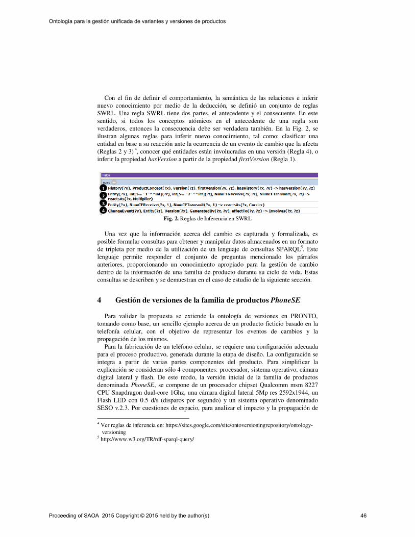
Con el fin de definir el comportamiento, la semántica de las relaciones e inferir
nuevo conocimiento por medio de la deducción, se definió un conjunto de reglas
SWRL. Una regla SWRL tiene dos partes, el antecedente y el consecuente. En este
sentido, si todos los conceptos atómicos en el antecedente de una regla son
verdaderos, entonces la consecuencia debe ser verdadera también. En la Fig. 2, se
ilustran algunas reglas para inferir nuevo conocimiento, tal como: clasificar una
entidad en base a su reacción ante la ocurrencia de un evento de cambio que la afecta
(Reglas 2 y 3) 4, conocer qué entidades están involucradas en una versión (Regla 4), o
inferir la propiedad hasVersion a partir de la propiedad firstVersion (Regla 1).
Fig. 2. Reglas de Inferencia en SWRL
Una vez que la información acerca del cambio es capturada y formalizada, es
posible formular consultas para obtener y manipular datos almacenados en un formato
de tripleta por medio de la utilización de un lenguaje de consultas SPARQL5. Este
lenguaje permite responder el conjunto de preguntas mencionado los párrafos
anteriores, proporcionando un conocimiento apropiado para la gestión de cambio
dentro de la información de una familia de producto durante su ciclo de vida. Estas
consultas se describen y se demuestran en el caso de estudio de la siguiente sección.
4 Gestión de versiones de la familia de productos PhoneSE
Para validar la propuesta se extiende la ontología de versiones en PRONTO,
tomando como base, un sencillo ejemplo acerca de un producto ficticio basado en la
telefonía celular, con el objetivo de representar los eventos de cambios y la
propagación de los mismos.
Para la fabricación de un teléfono celular, se requiere una configuración adecuada
para el proceso productivo, generada durante la etapa de diseño. La configuración se
integra a partir de varias partes componentes del producto. Para simplificar la
explicación se consideran sólo 4 componentes: procesador, sistema operativo, cámara
digital lateral y flash. De este modo, la versión inicial de la familia de productos
denominada PhoneSE, se compone de un procesador chipset Qualcomm msm 8227
CPU Snapdragon dual-core 1Ghz, una cámara digital lateral 5Mp res 2592x1944, un
Flash LED con 0.5 d/s (disparos por segundo) y un sistema operativo denominado
SESO v.2.3. Por cuestiones de espacio, para analizar el impacto y la propagación de
4 Ver reglas de inferencia en: https://sites.google.com/site/ontoversioningrepository/ontology-
versioning 5 http://www.w3.org/TR/rdf-sparql-query/
2
1
4
3
Proceeding of SAOA 2015 Copyright © 2015 held by the author(s) 46
Ontología para la gestión unificada de variantes y versiones de productos

cambios, este caso se basa en un único requerimiento que surgen durante la etapa de
diseño: “Incorporar una cámara digital frontal de 2Mp res 1733x1155”.
A partir de esta breve descripción, los cambios en una familia de productos puede
ocurrir en cualquiera de los niveles propuestos por PRONTO: Family, VariantSet y
Product. Dado que en el nivel más abstracto, las modificaciones están dadas en la
estructura de los productos que forman la familia. En el nivel intermedio pueden ser
cambiados la selección de componentes, así como las restricciones entre conjuntos de
variantes, y en el nivel más bajo puede verse afectada la especificación de los
productos concretos. Sin embargo, un cambio en un cierto nivel, puede generar
nuevos cambios en otro nivel. Por esto, se propone la especialización de la entidad
ProductConcept en los niveles: Family, VariantSet y Product, y para cada uno de
estos niveles, se identifican los elementos susceptibles de ser modificados y se
representan a través de la especialización de los conceptos Entity, ChangeEvent y
ActivityConstraint 6
Así, por ejemplo en el nivel de Familia, la entidad Entity se especializa en
CRelation/DRelation, FRestricion y QuantityPerUnit/ ProductionFactor. Estas
entidades son afectadas respectivamente por las especializaciones de ChangeEvent
FRestrictionCE, CRelationCE/ DRelationCE y QuantityPerUnitCE. En el nivel de
familia, se definen un conjunto de restricciones que especifican que sólo las
actividades Add y Delete, pueden afectar a FRestriction (FRestrictionAC) y a una
CRelation (CRelationAC). En contraste, QuantityPerUnit/ ProductionFactor pueden
ser afectados únicamente por un tipo de operación Edit (QuantityPerUnitAC). En el nivel de conjunto de variantes (VariantSet), se identifica las entidades
VSRestriction y Change como especializaciones de Entity. Estas entidades son
afectadas respectivamente por los siguientes eventos de cambios: VRestrictionCE,
FamilySpecificationCE, FamilyRemovalCE y QuantityChangeCE. Además, cada
entidad tiene asociada una restricción que controla el tipo de operación que puede
afectarla, tal como: VSRestrictionAC, QuantityChangeAC, FamilySpecificatonAC y
FamilyRemovalAC.En el nivel de Producto, las entidades que pueden ser modificadas
son: PRestriction y la relación chosenProduct, que se reifica en una entidad, dado que
es susceptible a los cambios en el modelo. Estas entidades pueden ser afectadas por
los eventos de cambio PRestrictionCE y ChosenProductCE, respectivamente.
Asimismo, estas entidades están limitadas por las restricciones PRestrictionAC y
ChosenProductAC. En la Fig. 3.a se representa el ejemplo descripto, instanciando el modelo de PRONTO, donde la familia de productos PhoneSE posee una estructura de
composición (SEStructure), la cual se vincula con sus partes componentes mediante
instancias de la clase CRelation. Para facilitar la comprensión, únicamente se muestra
el componente Processor con la relación de composición CR1 y su atributo
quantityPerUnit (CR1Value). En el nivel de conjunto de variantes se identifica la
variante SEMH, miembro de la Familia PhoneSE, que especifica su estructura de
composición a través de la relación has. SEMH restringe los conjuntos de variantes
que pueden usarse como componentes a los conjuntos de variantes: Qualcomm msm
8227, Lateral Camera 5Mp, FlashLED y SESO, miembros de Processor, Camera,
CameraFlash y SO, respectivamente. En la figura se representa únicamente el
6 Ver diagrama en el repositorio en:
https://sites.google.com/site/ontoversioningrepository/ontology-versioning
Proceeding of SAOA 2015 Copyright © 2015 held by the author(s) 47
Ontología para la gestión unificada de variantes y versiones de productos
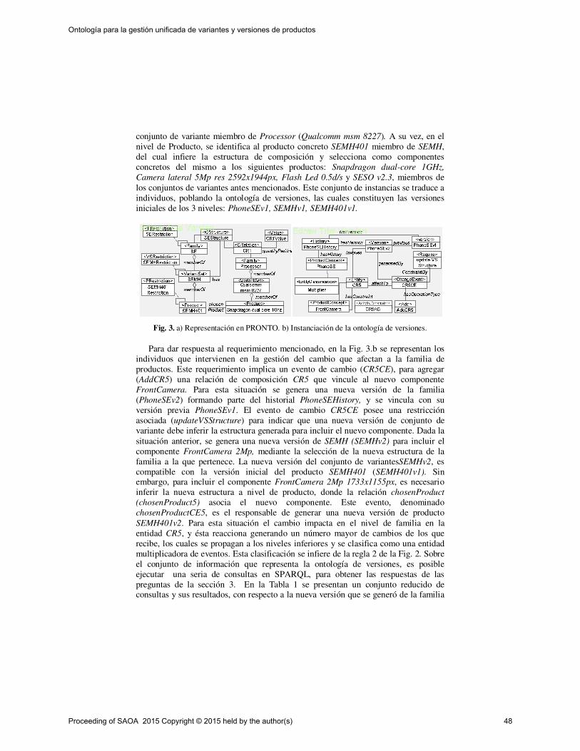
conjunto de variante miembro de Processor (Qualcomm msm 8227). A su vez, en el
nivel de Producto, se identifica al producto concreto SEMH401 miembro de SEMH,
del cual infiere la estructura de composición y selecciona como componentes
concretos del mismo a los siguientes productos: Snapdragon dual-core 1GHz,
Camera lateral 5Mp res 2592x1944px, Flash Led 0.5d/s y SESO v2.3, miembros de
los conjuntos de variantes antes mencionados. Este conjunto de instancias se traduce a
individuos, poblando la ontología de versiones, las cuales constituyen las versiones
iniciales de los 3 niveles: PhoneSEv1, SEMHv1, SEMH401v1.
Fig. 3. a) Representación en PRONTO. b) Instanciación de la ontología de versiones.
Para dar respuesta al requerimiento mencionado, en la Fig. 3.b se representan los
individuos que intervienen en la gestión del cambio que afectan a la familia de
productos. Este requerimiento implica un evento de cambio (CR5CE), para agregar
(AddCR5) una relación de composición CR5 que vincule al nuevo componente
FrontCamera. Para esta situación se genera una nueva versión de la familia
(PhoneSEv2) formando parte del historial PhoneSEHistory, y se vincula con su
versión previa PhoneSEv1. El evento de cambio CR5CE posee una restricción
asociada (updateVSStructure) para indicar que una nueva versión de conjunto de
variante debe inferir la estructura generada para incluir el nuevo componente. Dada la
situación anterior, se genera una nueva versión de SEMH (SEMHv2) para incluir el
componente FrontCamera 2Mp, mediante la selección de la nueva estructura de la
familia a la que pertenece. La nueva versión del conjunto de variantesSEMHv2, es
compatible con la versión inicial del producto SEMH401 (SEMH401v1). Sin embargo, para incluir el componente FrontCamera 2Mp 1733x1155px, es necesario
inferir la nueva estructura a nivel de producto, donde la relación chosenProduct
(chosenProduct5) asocia el nuevo componente. Este evento, denominado
chosenProductCE5, es el responsable de generar una nueva versión de producto
SEMH401v2. Para esta situación el cambio impacta en el nivel de familia en la
entidad CR5, y ésta reacciona generando un número mayor de cambios de los que
recibe, los cuales se propagan a los niveles inferiores y se clasifica como una entidad
multiplicadora de eventos. Esta clasificación se infiere de la regla 2 de la Fig. 2. Sobre
el conjunto de información que representa la ontología de versiones, es posible
ejecutar una seria de consultas en SPARQL, para obtener las respuestas de las
preguntas de la sección 3. En la Tabla 1 se presentan un conjunto reducido de consultas y sus resultados, con respecto a la nueva versión que se generó de la familia
Proceeding of SAOA 2015 Copyright © 2015 held by the author(s) 48
Ontología para la gestión unificada de variantes y versiones de productos
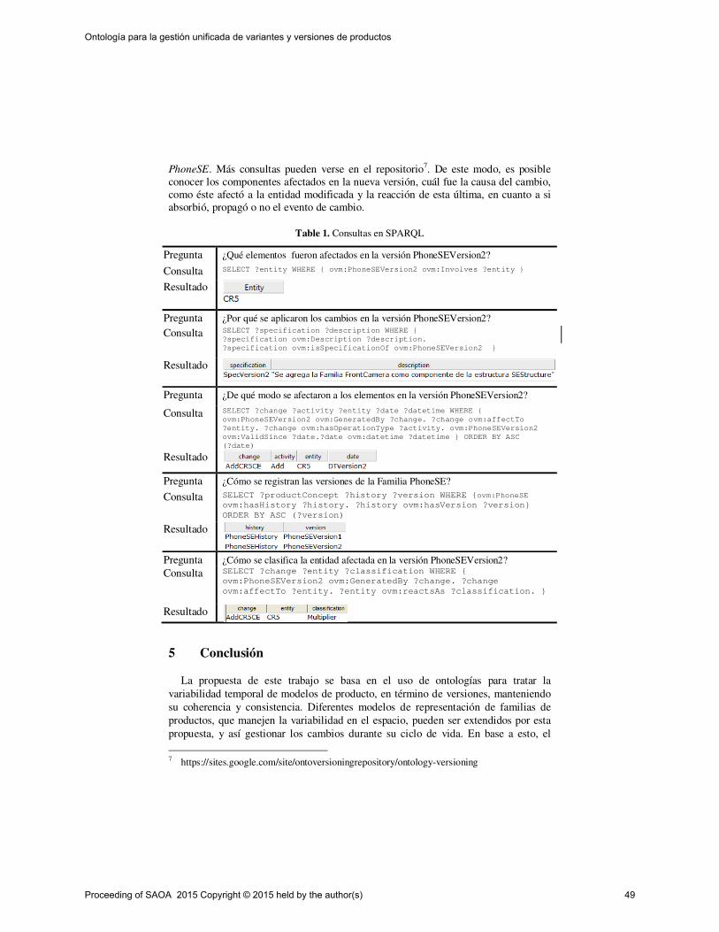
PhoneSE. Más consultas pueden verse en el repositorio7. De este modo, es posible
conocer los componentes afectados en la nueva versión, cuál fue la causa del cambio,
como éste afectó a la entidad modificada y la reacción de esta última, en cuanto a si
absorbió, propagó o no el evento de cambio.
Table 1. Consultas en SPARQL
Pregunta ¿Qué elementos fueron afectados en la versión PhoneSEVersion2?
Consulta SELECT ?entity WHERE ovm:PhoneSEVersion2 ovm:Involves ?entity
Resultado
Pregunta ¿Por qué se aplicaron los cambios en la versión PhoneSEVersion2?
Consulta SELECT ?specification ?description WHERE
?specification ovm:Description ?description.
?specification ovm:isSpecificationOf ovm:PhoneSEVersion2
Resultado
Pregunta ¿De qué modo se afectaron a los elementos en la versión PhoneSEVersion2?
Consulta SELECT ?change ?activity ?entity ?date ?datetime WHERE
ovm:PhoneSEVersion2 ovm:GeneratedBy ?change. ?change ovm:affectTo
?entity. ?change ovm:hasOperationType ?activity. ovm:PhoneSEVersion2
ovm:ValidSince ?date.?date ovm:datetime ?datetime ORDER BY ASC
(?date)
Resultado
Pregunta ¿Cómo se registran las versiones de la Familia PhoneSE?
Consulta SELECT ?productConcept ?history ?version WHERE ovm:PhoneSE
ovm:hasHistory ?history. ?history ovm:hasVersion ?version
ORDER BY ASC (?version)
Resultado
Pregunta ¿Cómo se clasifica la entidad afectada en la versión PhoneSEVersion2?
Consulta SELECT ?change ?entity ?classification WHERE
ovm:PhoneSEVersion2 ovm:GeneratedBy ?change. ?change
ovm:affectTo ?entity. ?entity ovm:reactsAs ?classification.
Resultado
5 Conclusión
La propuesta de este trabajo se basa en el uso de ontologías para tratar la
variabilidad temporal de modelos de producto, en término de versiones, manteniendo
su coherencia y consistencia. Diferentes modelos de representación de familias de
productos, que manejen la variabilidad en el espacio, pueden ser extendidos por esta
propuesta, y así gestionar los cambios durante su ciclo de vida. En base a esto, el
7 https://sites.google.com/site/ontoversioningrepository/ontology-versioning
Proceeding of SAOA 2015 Copyright © 2015 held by the author(s) 49
Ontología para la gestión unificada de variantes y versiones de productos

desarrollo de la propuesta de este trabajo permitió representar la gestión de versiones
de las familias de productos, extendiendo a PRONTO, junto a la definición de reglas
de inferencia SWRL que permitieron inferir nuevo conocimiento sobre un caso
concreto. Además, se escribieron consultas en SPARQL dando como resultado
información respecto a los cambios, al registro de versiones y a la reacción de los
elementos afectados por los cambios. De esta forma se logra validar la propuesta y,
desde una perspectiva funcional, se logra extender la representación de información
de familia de productos. Con el fin de mejorar la interpretación y la visualización de
imágenes, se generó un repositorio de datos para acceder a más detalles del contenido
de este trabajo.
A futuro, se pretende extender la propuesta teniendo en cuenta la propagación de
los cambios en diferentes niveles de PRONTO. Asimismo, se realizarán actividades
para complementar la validación de la propuesta y se trabajará en la identificación de
patrones de comportamientos repetitivos a fin de lograr predecir las consecuencias de
los cambios para una gestión eficiente de estos.
6 Agradecimientos
Se agradece el apoyo brindado por estas instituciones: CONICET, Univ. Tecnológica
Nacional (PID 25-O156 y PID 25-O144) y Universidad Nacional de La Rioja.
Referencias
1. M., Vegetti, H., Leone, H., Henning, G.: PRONTO: An ontology for comprehensive and
consistent representation of product information. Engineering Applications of Artificial
Intelligence 24 (8), pp. 1305-1327. (2011)
2. Pohl K., Bockle G., Van Der Linden F.: Software Product Line Engineering. Foundations,
principles, and Techniques. ISBN-10 3-540-24372-0 Springer Berlin Heidelberg New
York. (2006)
3. Shadbolt, N., W. Hall and T. Berness-Lee, (2006). The Semantic Web Revisited. IEEE
Intelligent Systems, May-Jun.
4. Brandt, S.C., J. Morbach, M. Miatidis, M. Theißen, M. Jarke and W. Marquardt, 2008. An
Ontology-Based Approach to Knowledge Management in Design Processes. Computers
and Chemical Engineering, 32, 320-342.
5. Männistö T, A Conceptual Modelling Approach to Product Families and their Evolution.
Acta Polytechnical Scandinavica, Mathematics and Computing Series. No. 106, ISSN
1456-9418.(2000)
6. Estublier J. and Casallas R. Three dimensional versioning. ICSE SCM-4 and SCM-5
Workshops Selected Papers. Software Configuration Management. Volume 1005, issue
1995, pp 118-135.ISBN 978-3-540-60578-2 (2005)
7. Sjoberg D. Managing Change in Information Systems: Technological Challenges.
Departament of Informatics, University of Oslo. N-0316 Oslo, Norway. (1995)
8. Ecker C., Clarkson J.P., Zanker W. Change and Customization in complex engineering
domains. Research in Engineering Design. Volume 15, Issue 1 pp 1-21. (2004)
Proceeding of SAOA 2015 Copyright © 2015 held by the author(s) 50
Ontología para la gestión unificada de variantes y versiones de productos
Redefinition and Statistical Analysis of Measuresfor Evaluating the Quality of Ontologies
Melina Tibaldo1, Alexia Wilkinson1, Ma. Laura Taverna1, Mariela Rico1, andMa. Rosa Galli2
1 Centro de Investigacion y Desarrollo de Ingenierıa en Sistemas de Informacion(CIDISI) - Universidad Tecnologica Nacional - Facultad Regional Santa Fe,
Lavaise 610 - S3004EWB - Santa Fe - SF - [email protected]
2 INGAR-UTN-CONICET, Avellaneda 3657, S3002GJC Santa Fe, Argentina
Abstract. OntoQualitas is a framework to evaluate an ontology whosepurpose is the interchange of information between different contexts.However, the framework does not propose acceptance thresholds of themeasure values. In this paper, measures proposed in this framework areredefined in order to improve their usefulness in assessing the quality ofsuch ontologies. These measures were calculated semi-automatically ona set of ontologies and its results were described by means of a statisticalanalysis as a first step to the definition of their acceptance thresholds.
Keywords: ontology quality, measure, statistical analysis
1 Introduction
Even after more than a decade since the emergence of ontologies in ComputerScience and with its growing use in different disciplines, standardized methodshave not been developed for evaluating their quality [8].
Although methodologies, methods, techniques, and software tools to sup-port the ontology building process were proposed, ontology evaluation still playsonly a passive role in ontology engineering projects [17]. In order to assess theontology quality, different works have emerged depending on the kind of ontolo-gies being evaluated and for what purpose [1, 3, 5–7, 9, 15, 20–22]. These workspresent different quality measures and evaluate some ontologies quantitatively.However, specific studies have not been found about the suitable values of thesemeasures, their acceptance thresholds, and their impact on the quality of theevaluated ontologies.
Quality is not a property of something, but a judgment, so that should be inrelation to some purpose [6]. While issues such as orphan classes or consistencyin naming are important, the purpose for which the ontology is developed shouldguide the evaluation of quality thus contributing to the enrichment of its quality.The set of measures and their corresponding weights should be in relation withthe purpose of the ontology [15].
Proceeding of SAOA 2015 Copyright © 2015 held by the author(s) 51

A proposed framework to evaluate an ontology considering its specific pur-pose is OntoQualitas, which includes known measures and new measures toevaluate the quality of an ontology whose purpose is the interchange of infor-mation in a collaborative business processes environment [15]. To this aim, a setof requirements is identified that the ontology should fulfill and, associated withthem, it is identified a set of questions that reflect specific aspects relevant tothe evaluation of ontology. For each question, appropriate measures, their rangesof possible values, and the optimal values are defined. However, the frameworkdoes not propose acceptance thresholds of the measure values.
In order to advance in the definition of these thresholds and their impact onthe ontology quality, the definition of the proposed measures should be analyzedand, if necessary, modified to ensure their homogeneity. Then, it is necessary tocalculate the measures on a set of ontologies and conduct a descriptive statisticalanalysis of the redefined measures in order to study their behavior.
This paper presents the reformulation of some of the measures outlined inOntoQualitas, resulting in measures that will be more convenient for evaluationof the ontology quality. In addition, a statistical study of a set of ontologies isshown, to whom the reformulated measures were calculated.
The paper is organized as follows: Section 2 describes the main characteristicsof the OntoQualitas framework; Section 3 presents the reformulated measures;Section 4 presents the results of the preliminary analysis of data. Results arediscussed in Section 5, which also includes the conclusions of this work.
2 OntoQualitas
OntoQualitas is a framework to evaluate the quality of an ontology whose pur-pose is the interchange of information between different contexts [15]. It is struc-tured from an overall requirement imposed on ontologies regarding its contentand structure, which is that the ontology should allow the interchange of infor-mation between different contexts without imposing a global meaning of suchinformation to all involved contexts. From this overall requirement, three spe-cific requirements are derived: (i) the representation of information interchangedshould be formal, (ii) only the information strictly necessary for the interchangemust be represented, and (iii) the representation must allow a correct interpre-tation of the interchanged information in all involved contexts.
The second requirement aforementioned has two aspects: completeness andconciseness. The third requirement has three aspects: semantic correctness, syn-tactic correctness, and representation correctness, which is assessing the qualityof mappings of entities, relations, and features into the elements of the ontology.
OntoQualitas specifies questions that help addressing relevant aspects forontology evaluation. For each question, appropriate measures are associated.Some of them have been proposed with the objective of assessing the quality ofontologies from a quantitative perspective [3, 5, 6, 20, 21]; others were proposedwith the aim of evaluating the mapping between domain entities, its relationshipsand features, and the elements used for its representation [13].
Proceeding of SAOA 2015 Copyright © 2015 held by the author(s) 52
Redefinition and Statistical Analysis of Measures for Evaluating the Quality of Ontologies

3 Analysis of Measures
In OntoQualitas, the value of some measures is provided in the range [0, 1],others are provided in the range [0, n], some optimal values are 1, and others are0. In order to quantify the different quality aspects and to compare values amongontologies, it is necessary to homogenize the value ranges and optimal values ofthe measures associated with each aspect. As a consequence, a first activity wasto modify the definition of some measures to ensure that all have the same scale([0, 1]) and optimal value (1). Additionally, some measures can only be calculatedif the considered ontology has the corresponding characteristics. These situationsare explicitly identified in Tables 1 to 5.
Completeness (Table 1) refers to the extension, degree, amount or coverageto which the information in a user-independent ontology covers the informationof the real world [11].
Concise (Table 2) refers to whether an ontology does not store any unnec-essary or useless definitions, if explicit redundancies do not exist between def-initions, and redundancies cannot be inferred using other definitions and ax-ioms [11].
Syntactic correctness (Table 3) tries to evaluate the quality of the ontologyaccording to the way it is written, i.e. the correctness and breadth of syntaxused [5].
Semantic correctness (Table 4) deals with the vocabulary used to represententities, relations, and features, and the correctness of the representation of theinterchanged information in the ontology.
Representation correctness (Table 5) is related to the quality of mappings ofentities, relations, and features into the elements of the ontology evaluated.
4 Results of Preliminary Analysis of Data
The results of this preliminary analysis are presented according to the secondand third requirements. Since the considered ontologies are formalized in OWL2,the representation of information interchanged is formal, thus achieving the firstrequirement.
In order to evaluate reformulations to the OntoQualitas measures, ontologiesfor information interchange between different contexts were needed. A set ofontologies created by students from the course “Development of ontology-basedinformation systems” have been developed from the same specific instructions.First, ontologies (called “base”) were developed by using an ontology learningtechnique. Then, the representation of entities, their relationships and featureswere enriched, using a proposed method [14]. These ontologies were called “en-riched”. Measures were calculated semi-automatically and the instructions werethe frame of reference.
In the base ontologies, certain measures could not be calculated due to lack ofthe corresponding characteristics. Therefore, in the subsequent statistical anal-ysis, the amount of data varies.
Proceeding of SAOA 2015 Copyright © 2015 held by the author(s) 53
Redefinition and Statistical Analysis of Measures for Evaluating the Quality of Ontologies
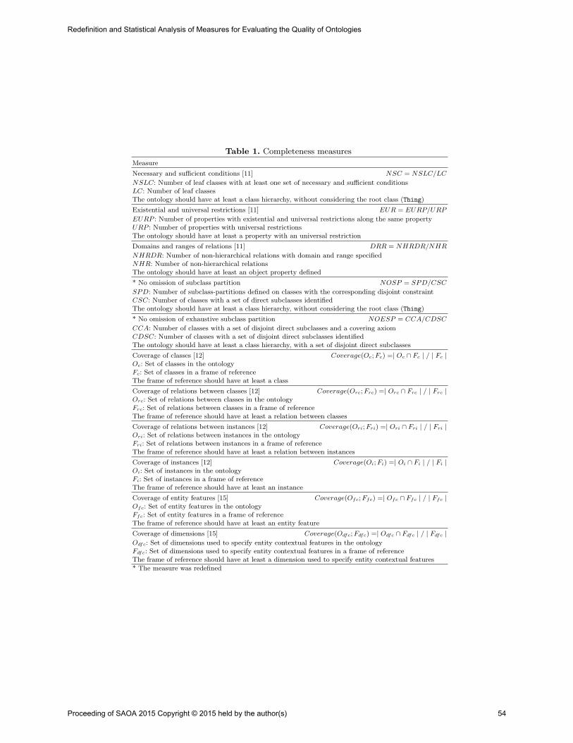
Table 1. Completeness measures
Measure
Necessary and sufficient conditions [11] NSC = NSLC/LC
NSLC: Number of leaf classes with at least one set of necessary and sufficient conditionsLC: Number of leaf classesThe ontology should have at least a class hierarchy, without considering the root class (Thing)
Existential and universal restrictions [11] EUR = EURP/URP
EURP : Number of properties with existential and universal restrictions along the same propertyURP : Number of properties with universal restrictionsThe ontology should have at least a property with an universal restriction
Domains and ranges of relations [11] DRR = NHRDR/NHR
NHRDR: Number of non-hierarchical relations with domain and range specifiedNHR: Number of non-hierarchical relationsThe ontology should have at least an object property defined
* No omission of subclass partition NOSP = SPD/CSC
SPD: Number of subclass-partitions defined on classes with the corresponding disjoint constraintCSC: Number of classes with a set of direct subclasses identifiedThe ontology should have at least a class hierarchy, without considering the root class (Thing)
* No omission of exhaustive subclass partition NOESP = CCA/CDSC
CCA: Number of classes with a set of disjoint direct subclasses and a covering axiomCDSC: Number of classes with a set of disjoint direct subclasses identifiedThe ontology should have at least a class hierarchy, with a set of disjoint direct subclasses
Coverage of classes [12] Coverage(Oc; Fc) =| Oc ∩ Fc | / | Fc |Oc: Set of classes in the ontologyFc: Set of classes in a frame of referenceThe frame of reference should have at least a class
Coverage of relations between classes [12] Coverage(Orc; Frc) =| Orc ∩ Frc | / | Frc |Orc: Set of relations between classes in the ontologyFrc: Set of relations between classes in a frame of referenceThe frame of reference should have at least a relation between classes
Coverage of relations between instances [12] Coverage(Ori; Fri) =| Ori ∩ Fri | / | Fri |Ori: Set of relations between instances in the ontologyFri: Set of relations between instances in a frame of referenceThe frame of reference should have at least a relation between instances
Coverage of instances [12] Coverage(Oi; Fi) =| Oi ∩ Fi | / | Fi |Oi: Set of instances in the ontologyFi: Set of instances in a frame of referenceThe frame of reference should have at least an instance
Coverage of entity features [15] Coverage(Ofc; Ffc) =| Ofc ∩ Ffc | / | Ffc |Ofc: Set of entity features in the ontologyFfc: Set of entity features in a frame of referenceThe frame of reference should have at least an entity feature
Coverage of dimensions [15] Coverage(Odfc; Fdfc) =| Odfc ∩ Fdfc | / | Fdfc |Odfc: Set of dimensions used to specify entity contextual features in the ontologyFdfc: Set of dimensions used to specify entity contextual features in a frame of referenceThe frame of reference should have at least a dimension used to specify entity contextual features
* The measure was redefined
Proceeding of SAOA 2015 Copyright © 2015 held by the author(s) 54
Redefinition and Statistical Analysis of Measures for Evaluating the Quality of Ontologies
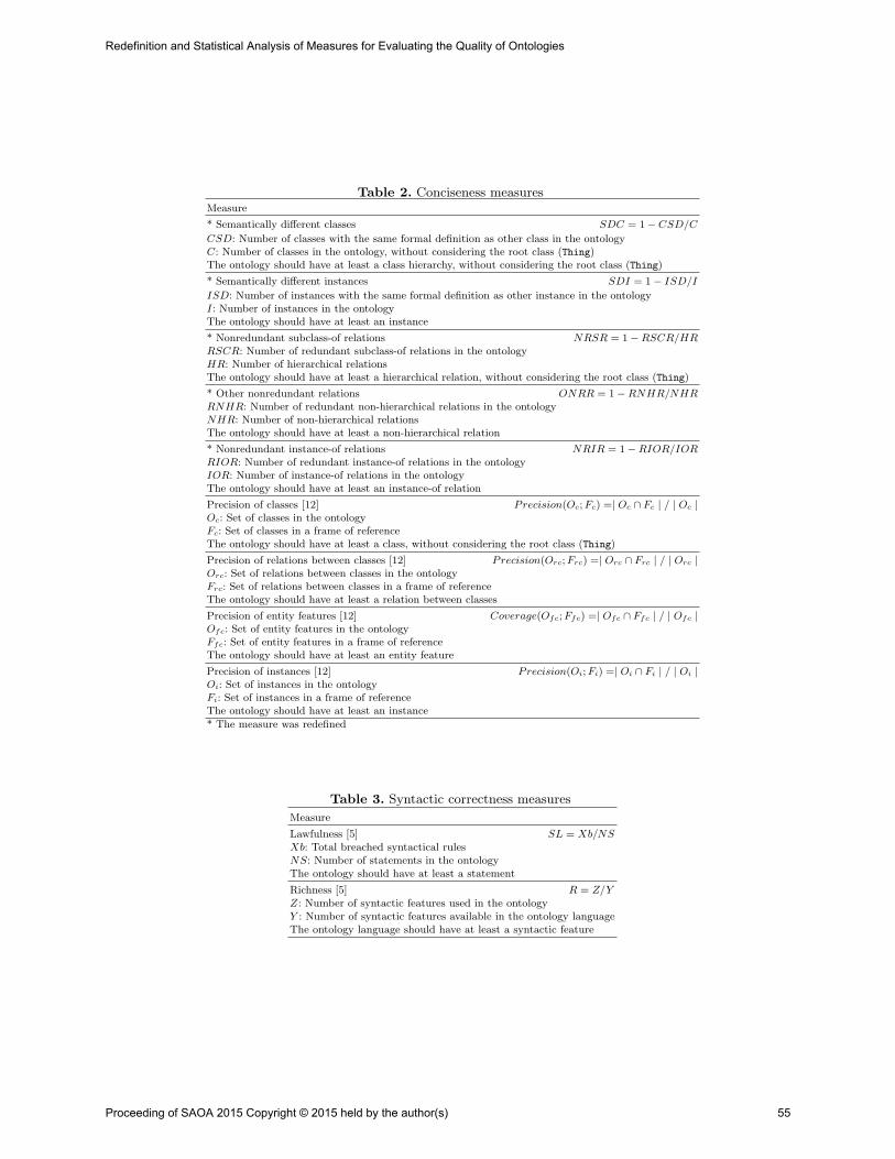
Table 2. Conciseness measuresMeasure
* Semantically different classes SDC = 1− CSD/C
CSD: Number of classes with the same formal definition as other class in the ontologyC: Number of classes in the ontology, without considering the root class (Thing)The ontology should have at least a class hierarchy, without considering the root class (Thing)
* Semantically different instances SDI = 1− ISD/I
ISD: Number of instances with the same formal definition as other instance in the ontologyI: Number of instances in the ontologyThe ontology should have at least an instance
* Nonredundant subclass-of relations NRSR = 1−RSCR/HRRSCR: Number of redundant subclass-of relations in the ontologyHR: Number of hierarchical relationsThe ontology should have at least a hierarchical relation, without considering the root class (Thing)
* Other nonredundant relations ONRR = 1−RNHR/NHRRNHR: Number of redundant non-hierarchical relations in the ontologyNHR: Number of non-hierarchical relationsThe ontology should have at least a non-hierarchical relation
* Nonredundant instance-of relations NRIR = 1−RIOR/IORRIOR: Number of redundant instance-of relations in the ontologyIOR: Number of instance-of relations in the ontologyThe ontology should have at least an instance-of relation
Precision of classes [12] Precision(Oc; Fc) =| Oc ∩ Fc | / | Oc |Oc: Set of classes in the ontologyFc: Set of classes in a frame of referenceThe ontology should have at least a class, without considering the root class (Thing)
Precision of relations between classes [12] Precision(Orc; Frc) =| Orc ∩ Frc | / | Orc |Orc: Set of relations between classes in the ontologyFrc: Set of relations between classes in a frame of referenceThe ontology should have at least a relation between classes
Precision of entity features [12] Coverage(Ofc; Ffc) =| Ofc ∩ Ffc | / | Ofc |Ofc: Set of entity features in the ontologyFfc: Set of entity features in a frame of referenceThe ontology should have at least an entity feature
Precision of instances [12] Precision(Oi; Fi) =| Oi ∩ Fi | / | Oi |Oi: Set of instances in the ontologyFi: Set of instances in a frame of referenceThe ontology should have at least an instance
* The measure was redefined
Table 3. Syntactic correctness measures
Measure
Lawfulness [5] SL = Xb/NSXb: Total breached syntactical rulesNS: Number of statements in the ontologyThe ontology should have at least a statement
Richness [5] R = Z/YZ: Number of syntactic features used in the ontologyY : Number of syntactic features available in the ontology languageThe ontology language should have at least a syntactic feature
Proceeding of SAOA 2015 Copyright © 2015 held by the author(s) 55
Redefinition and Statistical Analysis of Measures for Evaluating the Quality of Ontologies
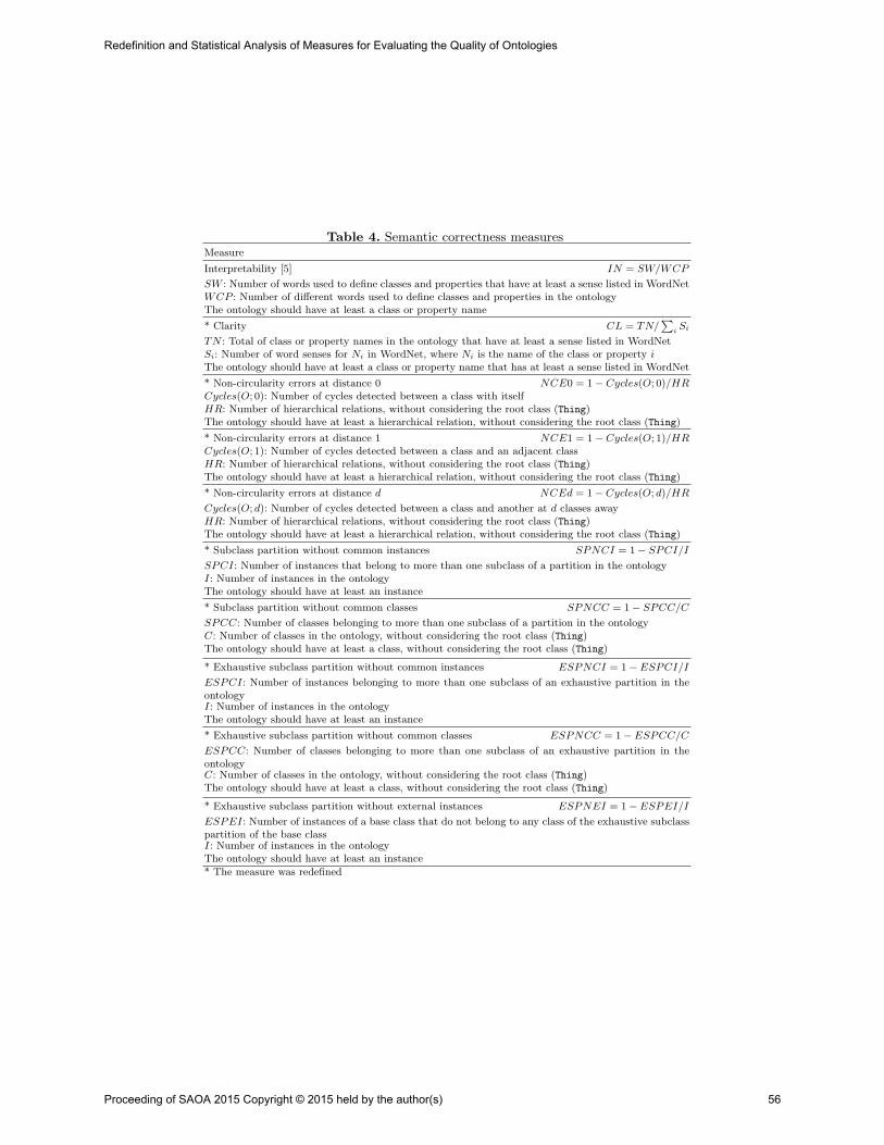
Table 4. Semantic correctness measuresMeasure
Interpretability [5] IN = SW/WCP
SW : Number of words used to define classes and properties that have at least a sense listed in WordNetWCP : Number of different words used to define classes and properties in the ontologyThe ontology should have at least a class or property name
* Clarity CL = TN/∑
iSi
TN : Total of class or property names in the ontology that have at least a sense listed in WordNetSi: Number of word senses for Ni in WordNet, where Ni is the name of the class or property iThe ontology should have at least a class or property name that has at least a sense listed in WordNet
* Non-circularity errors at distance 0 NCE0 = 1− Cycles(O; 0)/HRCycles(O; 0): Number of cycles detected between a class with itselfHR: Number of hierarchical relations, without considering the root class (Thing)The ontology should have at least a hierarchical relation, without considering the root class (Thing)
* Non-circularity errors at distance 1 NCE1 = 1− Cycles(O; 1)/HRCycles(O; 1): Number of cycles detected between a class and an adjacent classHR: Number of hierarchical relations, without considering the root class (Thing)The ontology should have at least a hierarchical relation, without considering the root class (Thing)
* Non-circularity errors at distance d NCEd = 1− Cycles(O; d)/HR
Cycles(O; d): Number of cycles detected between a class and another at d classes awayHR: Number of hierarchical relations, without considering the root class (Thing)The ontology should have at least a hierarchical relation, without considering the root class (Thing)
* Subclass partition without common instances SPNCI = 1− SPCI/I
SPCI: Number of instances that belong to more than one subclass of a partition in the ontologyI: Number of instances in the ontologyThe ontology should have at least an instance
* Subclass partition without common classes SPNCC = 1− SPCC/C
SPCC: Number of classes belonging to more than one subclass of a partition in the ontologyC: Number of classes in the ontology, without considering the root class (Thing)The ontology should have at least a class, without considering the root class (Thing)
* Exhaustive subclass partition without common instances ESPNCI = 1− ESPCI/I
ESPCI: Number of instances belonging to more than one subclass of an exhaustive partition in theontologyI: Number of instances in the ontologyThe ontology should have at least an instance
* Exhaustive subclass partition without common classes ESPNCC = 1− ESPCC/C
ESPCC: Number of classes belonging to more than one subclass of an exhaustive partition in theontologyC: Number of classes in the ontology, without considering the root class (Thing)The ontology should have at least a class, without considering the root class (Thing)
* Exhaustive subclass partition without external instances ESPNEI = 1− ESPEI/I
ESPEI: Number of instances of a base class that do not belong to any class of the exhaustive subclasspartition of the base classI: Number of instances in the ontologyThe ontology should have at least an instance
* The measure was redefined
Proceeding of SAOA 2015 Copyright © 2015 held by the author(s) 56
Redefinition and Statistical Analysis of Measures for Evaluating the Quality of Ontologies

Table 5. Representation correctness measures
Measure
Principle of entities [15] PE =∑
kαk/E
E: number of entitiesThe ontology should have at least an entity
Principle of intended use of entities [15] PU =∑
kαk/U
U : number of intended uses for all entitiesThe ontology should have at least an intended use for an entity
Principle of entity relations [15] PR =∑
kαk/RE
RE: number of relations identified for all entitiesThe ontology should have at least a relation between entities
Principle of simple entity features [15] PCS =∑
kαk/CS
CS: number of simple entity features identified for all entitiesThe ontology should have at least a simple entity feature
Principle of simple, measurable entity features [15] PCM =∑
kαk/CM
CM : number of simple, measurable entity features identified for all entitiesThe ontology should have at least a simple, measurable entity feature
Principle of complex entity features [15] PCC =∑
kαk/CC
CC: number of complex entity features identified for all entitiesThe ontology should have at least a complex entity feature
Principle of common entity features [15] PCc =∑
kαk/Cc
Cc: number of common entity features identified for all entitiesThe ontology should have at least a common entity feature
αk = 0 if the k element is not represented; αk = 0.5 if the k element is represented in an incompleteform; and αk = 1 if the k element is well represented
4.1 Evaluation of Measures
A statistical treatment of the data was performed in order to highlight themost important quality characteristics of ontologies and synthesize them by afew parameters. A total of 39 measures were calculated semi-automatically toa set of 8 ontologies. InfoStat, Student Version3, was used to do the statisticalanalysis of this set of measures. Mean lets see the behavior of each measure onthe set of ontologies; position measures, the dispersion of data (deviation; Q1,first quartile; and Q3, third quartile).
Table 6. Statistical of completeness measuresMedidas de completitud
Variable n Mean S.D. Min Max Q1 Median Q3NSC 6 0,17 0,41 0,00 1,00 0,00 0,00 0,00EUR 8 0,15 0,35 0,00 1,00 0,00 0,00 0,00DRR 8 0,63 0,41 0,00 1,00 0,00 0,82 0,87NOSP 6 0,09 0,13 0,00 0,30 0,00 0,03 0,19NOESP 3 0,50 0,50 0,00 1,00 0,50Coverage(Oc;Fc) 8 0,22 0,07 0,16 0,36 0,16 0,20 0,24Coverage(Orc;Frc) 8 0,36 0,23 0,10 0,70 0,10 0,35 0,50Coverage(Ofc;Ffc) 8 0,02 0,03 0,00 0,07 0,00 0,01 0,04Coverage(Odfc;Fdfc) 8 0,93 0,15 0,58 1,00 0,90 1,00 1,00
Medidas de concisión
Variable n Mean S.D. Min Max Q1 Median Q3SDC 6 0,75 0,28 0,39 1,00 0,53 0,78 1,00SDI 4 1,00 0,00 1,00 1,00 1,00 1,00 1,00NRSR 6 1,00 0,00 1,00 1,00 1,00 1,00 1,00ONRR 7 0,86 0,38 0,00 1,00 1,00 1,00 1,00NRIR 4 1,00 0,00 1,00 1,00 1,00 1,00 1,00Precision(Oc;Fc) 8 0,33 0,20 0,07 0,57 0,08 0,31 0,50Precision(Orc;Frc) 8 0,16 0,16 0,02 0,38 0,03 0,07 0,33Precision(Ofc;Ffc) 8 0,00 0,00 0,00 0,00 0,00 0,00 0,00Precision(Oi;Fi) 4 0,00 0,00 0,00 0,00 0,00 0,00 0,00
Table 7. Statistical of conciseness measures
Medidas de completitud
Variable n Mean S.D. Min Max Q1 Median Q3NSC 6 0,17 0,41 0,00 1,00 0,00 0,00 0,00EUR 8 0,15 0,35 0,00 1,00 0,00 0,00 0,00DRR 8 0,63 0,41 0,00 1,00 0,00 0,82 0,87NOSP 6 0,09 0,13 0,00 0,30 0,00 0,03 0,19NOESP 3 0,50 0,50 0,00 1,00 0,50Coverage(Oc;Fc) 8 0,22 0,07 0,16 0,36 0,16 0,20 0,24Coverage(Orc;Frc) 8 0,36 0,23 0,10 0,70 0,10 0,35 0,50Coverage(Ofc;Ffc) 8 0,02 0,03 0,00 0,07 0,00 0,01 0,04Coverage(Odfc;Fdfc) 8 0,93 0,15 0,58 1,00 0,90 1,00 1,00
Medidas de concisión
Variable n Mean S.D. Min Max Q1 Median Q3SDC 6 0,75 0,28 0,39 1,00 0,53 0,78 1,00SDI 4 1,00 0,00 1,00 1,00 1,00 1,00 1,00NRSR 6 1,00 0,00 1,00 1,00 1,00 1,00 1,00ONRR 7 0,86 0,38 0,00 1,00 1,00 1,00 1,00NRIR 4 1,00 0,00 1,00 1,00 1,00 1,00 1,00Precision(Oc;Fc) 8 0,33 0,20 0,07 0,57 0,08 0,31 0,50Precision(Orc;Frc) 8 0,16 0,16 0,02 0,38 0,03 0,07 0,33Precision(Ofc;Ffc) 8 0,00 0,00 0,00 0,00 0,00 0,00 0,00Precision(Oi;Fi) 4 0,00 0,00 0,00 0,00 0,00 0,00 0,00
3 http://www.infostat.com.ar/
Proceeding of SAOA 2015 Copyright © 2015 held by the author(s) 57
Redefinition and Statistical Analysis of Measures for Evaluating the Quality of Ontologies

Regarding completeness (Table 6), only two of the nine measures have amean greater than 0.6. The measure with the highest mean value is Coverageof dimensions (Coverage(Odfc;Fdfc)); 90.0% of ontologies have a value greaterthan or equal to 0.9, meaning that most of the dimensions used to specify en-tity contextual features were made explicit in the ontology. Then, Domains andranges of relations (DRR) follows with a mean of 0.63, which determines theproportion of domain and range of the relations and functions exactly and pre-cisely delimited. The frame of reference had no instances. Then, the measuresCoverage of relations between instances and Coverage of instances, not listed inTable 6, could not be calculated.
In regards to conciseness (Table 7), except in Precision, all other measureshave high values. Half of ontologies have all of instances semantically differentand nonredundant instance-of relations (SDI and NRIR are optimal). The otherhalf has no instances. No ontologies with hierarchical relations have redundantsubclass-of relations (NRSR has optimum value in all measures). Semanticallydifferent classes (SDC) has a mean of 0.75 and 75% of ontologies have a valuegreater than or equal to 0.53, meaning that more than half of subclasses aredefined with different characteristics. 75% of ontologies do not have redundantnon-hierarchical relations (ONRR is optimal).
Table 8. Statistical of semantic correctness
measures
Correctitud sintáctica
Variable n Mean S.D. Min Max Q1 Median Q3SL 8 1,00 0,00 1,00 1,00 1,00 1,00 1,00R 8 0,05 0,03 0,01 0,11 0,03 0,03 0,05
Correctitud semántica
Variable n Mean S.D. Min Max Q1 Median Q3IN 8 0,52 0,28 0,21 0,96 0,31 0,43 0,50CL 8 0,34 0,14 0,13 0,52 0,15 0,40 0,40NCE0 6 1,00 0,00 1,00 1,00 1,00 1,00 1,00NCE1 6 1,00 0,00 1,00 1,00 1,00 1,00 1,00NCEd 6 1,00 0,00 1,00 1,00 1,00 1,00 1,00SPNCI 4 0,75 0,50 0,00 1,00 0,00 1,00 1,00SPNCC 8 0,96 0,06 0,88 1,00 0,88 1,00 1,00ESPNCI 4 1,00 0,00 1,00 1,00 1,00 1,00 1,00ESPNCC 8 1,00 0,00 1,00 1,00 1,00 1,00 1,00ESPNEI 4 1,00 0,00 1,00 1,00 1,00 1,00 1,00
Correctitud de representación
Variable n Mean S.D. Min Max Q1 Median Q3PE 8 0,10 0,04 0,06 0,17 0,06 0,11 0,13PU 8 0,90 0,09 0,80 1,00 0,83 0,88 1,00PR 8 0,36 0,23 0,10 0,70 0,10 0,35 0,50PCS 4 0,90 0,13 0,75 1,00 0,75 0,92 1,00PCM 4 0,63 0,48 0,00 1,00 0,00 0,75 1,00
Table 9. Statistical of syntactic correctness
measuresCorrectitud sintáctica
Variable n Mean S.D. Min Max Q1 Median Q3SL 8 1,00 0,00 1,00 1,00 1,00 1,00 1,00R 8 0,05 0,03 0,01 0,11 0,03 0,03 0,05
Correctitud semántica
Variable n Mean S.D. Min Max Q1 Median Q3IN 8 0,52 0,28 0,21 0,96 0,31 0,43 0,50CL 8 0,34 0,14 0,13 0,52 0,15 0,40 0,40NCE0 6 1,00 0,00 1,00 1,00 1,00 1,00 1,00NCE1 6 1,00 0,00 1,00 1,00 1,00 1,00 1,00NCEd 6 1,00 0,00 1,00 1,00 1,00 1,00 1,00SPNCI 4 0,75 0,50 0,00 1,00 0,00 1,00 1,00SPNCC 8 0,96 0,06 0,88 1,00 0,88 1,00 1,00ESPNCI 4 1,00 0,00 1,00 1,00 1,00 1,00 1,00ESPNCC 8 1,00 0,00 1,00 1,00 1,00 1,00 1,00ESPNEI 4 1,00 0,00 1,00 1,00 1,00 1,00 1,00
Correctitud de representación
Variable n Mean S.D. Min Max Q1 Median Q3PE 8 0,10 0,04 0,06 0,17 0,06 0,11 0,13PU 8 0,90 0,09 0,80 1,00 0,83 0,88 1,00PR 8 0,36 0,23 0,10 0,70 0,10 0,35 0,50PCS 4 0,90 0,13 0,75 1,00 0,75 0,92 1,00PCM 4 0,63 0,48 0,00 1,00 0,00 0,75 1,00
Table 10. Statistical of representation correct-
ness measures
Correctitud sintáctica
Variable n Mean S.D. Min Max Q1 Median Q3SL 8 1,00 0,00 1,00 1,00 1,00 1,00 1,00R 8 0,05 0,03 0,01 0,11 0,03 0,03 0,05
Correctitud semántica
Variable n Mean S.D. Min Max Q1 Median Q3IN 8 0,52 0,28 0,21 0,96 0,31 0,43 0,50CL 8 0,34 0,14 0,13 0,52 0,15 0,40 0,40NCE0 6 1,00 0,00 1,00 1,00 1,00 1,00 1,00NCE1 6 1,00 0,00 1,00 1,00 1,00 1,00 1,00NCEd 6 1,00 0,00 1,00 1,00 1,00 1,00 1,00SPNCI 4 0,75 0,50 0,00 1,00 0,00 1,00 1,00SPNCC 8 0,96 0,06 0,88 1,00 0,88 1,00 1,00ESPNCI 4 1,00 0,00 1,00 1,00 1,00 1,00 1,00ESPNCC 8 1,00 0,00 1,00 1,00 1,00 1,00 1,00ESPNEI 4 1,00 0,00 1,00 1,00 1,00 1,00 1,00
Correctitud de representación
Variable n Mean S.D. Min Max Q1 Median Q3PE 8 0,10 0,04 0,06 0,17 0,06 0,11 0,13PU 8 0,90 0,09 0,80 1,00 0,83 0,88 1,00PR 8 0,36 0,23 0,10 0,70 0,10 0,35 0,50PCS 4 0,90 0,13 0,75 1,00 0,75 0,92 1,00PCM 4 0,63 0,48 0,00 1,00 0,00 0,75 1,00
In relation to the semantic correctness (Table 8), the measures are mostlyhigh. The hierarchies are well defined, without cycles (NCE0, NCE1, andNCED), as well as the exhaustive subclass partitions (ESPNCI, ESPNCC,and ESPNEI). By contrast, ontologies are moderately interpretable and un-clear; 75% of them have a value less than or equal to 0.5 and 0.4, respectively.
As for syntactic correctness (Table 9), it can be observed that the ontologiesare syntactically correct, but the proportion of syntactic features used is verylow, despite the development of ontologies supported by a case tool.
Finally, as to the representation correctness (Table 10), on average, 90%of the intended use and simple features of entities is represented according toits principle. However, only in 10% of cases, on average, the representation ofentities is performed through classes of ontology. The measures Principle of
Proceeding of SAOA 2015 Copyright © 2015 held by the author(s) 58
Redefinition and Statistical Analysis of Measures for Evaluating the Quality of Ontologies

complex entity features and Principle of common entity features could not becalculated because the ontologies do not have these characteristics.
5 Discussion and Conclusions
In this paper, the reformulation of some measures of the OntoQualitas frameworkhas been presented, and the results of a preliminary analysis over the valuesobtained from applying such measures to a set of ontologies have been shown.
According to the results, the evaluated ontologies do not fulfill adequately thesecond requirement, i.e., the representation of the information strictly necessaryfor the interchange. In part, this may be due to the ontology learning tool used togenerate the base ontologies that do not add necessary and sufficient conditions,or existential and universal restrictions, among others.
Looking at the syntactic correctness measures, it can be observed that therichness of language was not seized, despite the use of case tools for the develop-ment of ontologies. The use of ontology learning techniques contributed to this,as only limited to map the elements of the source into the ontology languageelements, untapped all syntactic features available.
As for the semantic interpretation, measures revealed that the names for theontology elements (classes, relations, properties) were not properly selected.
Regarding the representation correctness, an unexpected result is the lowrepresentation of entities through the ontology classes.
Finally, these measures allow detecting errors in the development of ontolo-gies, which affects its quality. An exploratory analysis of the data allowed tocharacterize the studied ontologies. Future work is to carry out an inferentialstatistical analysis to a larger set of ontologies that allows analyzing the possibleinterdependence between measures, define acceptance thresholds of measures,and propose a strategy for assessing the quality of ontologies.
References
1. Alani, H., Brewster, C., Shadbolt, N.: Ranking ontologies with AKTiveRank. 5thInternational Semantic Web Conference, ISWC. LNCS 4273, 1–15 (2006)
2. Alvarez Suarez, M.M., Caballero, A., Perez Lechuga, G.: Analisis multivariante:Clasificacion, organizacion y validacion de resultados. 4th Int. Latin American &Caribbean Conference for Engineering and Technology (LACCET) (2006)
3. Brank, J., Grobelink, M., Mladenic, D.: A survey of ontology evaluation techniques.Conference on Data Mining and Data Warehouses (SiKDD), 166–169 (2005)
4. Breitman, K.K., Casanova, M.A., Truszkowski, W.: Semantic Web: Concepts, tech-nologies and applications. NASA monographs in systems and software engineering.Springer-Verlag London Limited (2007)
5. Burton-Jones, A., Storey, V.C., Sugumaran, V., Ahluwalia, P.: A semiotic metricssuite for assessing the quality of ontologies. Data Knowl. Eng. 55(1), 84–102 (2005)
6. Colomb, R.M.: Quality of ontologies in interoperating information systems. Techni-cal report 18/02 ISIB-CNR, Padova, Italy (2002)
Proceeding of SAOA 2015 Copyright © 2015 held by the author(s) 59
Redefinition and Statistical Analysis of Measures for Evaluating the Quality of Ontologies
7. Duque-Ramos, A., Fernandez-Breis, J., Stevens, R., Aussenac-Gilles, N.: OQuaRE:A SQuaRE-based approach for evaluating the quality of ontologies. J. Res. Pract.Inf. Tech. 43(2), 159–176 (2011)
8. Duque-Ramos, A., Fernandez-Breis, J., Iniesta, M., Dumontier, M., EganaAranguren, M., Schulz, S., Aussenac-Gilles, N., Stevens, R.: Evaluation of theOquaRE framework for ontology quality. Expert Syst. Appl. 40, 2669–2703 (2013)
9. Gangemi, A., Catenacci, C., Ciaramita, M., Lehmann, J.: Ontology evaluation andvalidation. The Semantic Web: Research and Applications. 3rd European SemanticWeb Conference, ESWC, Proceedings, LNCS 4011, 140–154 (2006)
10. Gasevic, D., Djuric, D., Devedzic, V.: Model driven architecture and ontologydevelopment. Springer-Verlag New York, Inc., Secaucus, NJ, USA (2006)
11. Gomez-Perez, A.: Evaluation of ontologies. Int. J. Intell. Syst. 16, 391–409 (2001)12. Guarino, N.: Towards a formal evaluation of ontology quality. IEEE Intell. Syst.
19(4), 74-81 (2004)13. Rico, M.: Soporte para enriquecer la representacion de entidades en una ontologıa.
Tesis doctoral, Universidad Tecnologica Nacional, Fac. Reg. Santa Fe, AR (2011)14. Rico, M., Caliusco, M.L., Chiotti, O., Galli, M.R.: An approach to define
semantics for BPM systems interoperability. Enterprise Information Systems,DOI:10.1080/17517575.2013.767381 (2013)
15. Rico, M., Caliusco, M.L., Chiotti, O., Galli, M.R.: OntoQualitas: A frameworkfor ontology quality assessment in information interchanges between heterogeneoussystems. Comput. Ind. 65(9), 1291–1300 (2014)
16. Romero Villafranca, R.: Curso de introduccion a los metodos de analisis estadısticomultivariante. Universitat Politecnica de Valencia, SP.UPV.95–606 (1995)
17. Simperl, E., Mochol, M., Burger, T.: Achieving maturity: The state of practice inontology engineering in 2009. Int. J. Comput. Sci. Appl. 7(1), 45–65 (2010)
18. Staab, S., Studer, R. (Eds.): Handbook on ontologies. International handbooks oninformation systems. 2nd edn. Springer-Verlag Berlin Heidelberg (2009)
19. Studer, R., Benjamins, V.R., Fensel, D.: Knowledge engineering: Principles andmethods. Data. Knowl. Eng. 25(1-2), 161–197 (1998)
20. Stvilia, B.: A model for ontology quality evaluation. First Monday 12(12) (2007)21. Tartir, S., Arpinar, I.B.: Ontology evaluation and ranking using OntoQA. Interna-
tional Conference on Semantic Computing, ICSC, 185–192 (2007)22. Vrandecic, D.: Ontology evaluation. PhD Thesis. Institute AIFB, University of
Karlsruhe, Germany (2010)
Proceeding of SAOA 2015 Copyright © 2015 held by the author(s) 60
Redefinition and Statistical Analysis of Measures for Evaluating the Quality of Ontologies
Extension Rules for Ontology Evolution within a
Conceptual Modelling Tool
German Braun1,2 and Laura Cecchi1
1Grupo de Investigacion en Lenguajes e Inteligencia ArtificialDepartamento de Teorıa de la Computacion - Facultad de Informatica
Universidad Nacional del Comahue2Consejo Nacional de Investigaciones Cientıficas y Tecnicas (CONICET)
Abstract Ontology development and maintenance are complex tasks,so automatic tools are essential for a successful integration between themodeller’s intention and the formal semantics in an ontology. Never-theless, tools need to provide a way to capture the intuitive structuresinherent to the conceptual modelling and to focus on ontology elementscurrently being refactored by abstracting the user from the whole ontol-ogy without losing consistency. This can be done by means of a set ofextension rules that identify elements from an ontology and suggest pos-sible consistent evolutions. Rules guide the development of ontologiesby taking source elements and refactoring. In this paper, we present asmall catalogue of extension rules to cover these identified requirementsand thus to be integrated into a tool for ontological modelling as built-in reasoning services. Each rule is defined and analysed by consideringdifferent theories of design patterns.
1 Introduction and Motivation
Ontology development and maintenance are complex tasks, so automatic toolsare essential for a successful integration between the modeller’s intention andthe formal semantics in an ontology. Domain experts capture the knowledge inthe universe of discourse but they have a limited understanding of the semanticsof ontology representation languages. Moreover, a good comprehension of theimplicit knowledge in a middle-size ontology formalisation is difficult even for ITexperts. Thus, automatic tools are essential for a successful integration betweenthe modeller’s intention and the formal semantics in an ontology.
Two of the most important features for any ontology development tool aresupport for graphical representation and a consistent integration with a back-end reasoner for helping in the management of implicit knowledge. Nevertheless,tools also need to provide a way to capture the modeller’s intentions or theintuitive structures inherent to the conceptual modelling. The first ones aresources for abstractions and for exploring, composing and checking the ontologyby making explicit to the user its overall semantic. The last one provides away to focus on ontology elements currently being refactored by abstractingthe user from the whole ontology maintaining consistency and giving support
Proceeding of SAOA 2015 Copyright © 2015 held by the author(s) 61
2 Braun German and Cecchi Laura
to the ontological evolution. This can be done by means of a set of extensionrules that identify elements from an ontology and suggest possible consistentevolutions. Rules guide the development of ontologies by taking source elementsand refactoring together with the underlying reasoning services.
In order to offer rules-based support, some efforts have been undertaken. Inparticular, Guizzardi et al. [1] propose an automatic model-checking editor thattakes advantage of a well-behaved and predefined set of design patterns. Unlikeour approach, the modelling rules are derived from this set of patterns and areimplemented by means of an interactive dialogue between the modeller and anautomated tool running these rule sets. Interfaces with reasoning systems havenot been considered in this work.
In this paper, we present a set of extension rules which work at intentionallevel (TBox) of an ontology. An extension rule is a Description Logic (DL) struc-ture with an antecedent which must be satisfied in the model to be applied, anda consequent which contains the new knowledge to be asserted. Extension rulesare to be used together with other artefacts as user queries and reasoning sys-tems, where the former identifies relevant parts of an ontology and the latterinquires the model to check rules applicability, their possible consequences andside effects. A rule is applicable iff its antecedent is satisfied and its consequentmaintains the consistency of the model. Our rules-based approach and the ontol-ogy design patterns [2] can be considered as complementary since both providea foundation for modularity to maintain and reduce the complexity of designingand understanding ontologies. Our alternative offers flexibility and a fine-grainedlevel where the focus is on a reduced set of graphical elements to analyse so asto introduce new ones, as opposed to design patterns which are not orientatedtowards ontology evolution since they involve more elements in their definitionsthan rules. Similar to the design patterns, the rules allow to describe views inwhich the evolution suggestions are consistent. As a consequence, they have theeffect of changing only the ontology elements involved in the refactoring, whichcan be intra- or inter-ontology elements. In addition, rules present modularityas a key property so that they could be modified and extended without affectingthe host methodology.
This rule-based approach is to be implemented on the methodology under-lying to ICOM tool [3, 4, 5] extending the reasoning services provided by thetool. In this context, we will consider its graphical primitives and its translationto the underlying DL ALCQI as our initial development framework. ICOM isan advanced conceptual modelling tool, which allows the user to design mul-tiple diagrams adopting as neutral language a hybrid of an EER and UMLlanguages with inter- and intra-schema constraints. Complete logical reasoningis employed by the tool to verify the specification, infer implicit axioms, i.e. newintentional knowledge, devise stricter constraints and manifest any inconsist-ency. The leverage of automated reasoning to support the domain modelling isenabled by a precise semantic definition of all the elements of the class diagrams.ICOM graphical language can be represented in ALCQI, although the graph-ical language cannot express inverse roles. ALCHIQ is necessary for the full
Proceeding of SAOA 2015 Copyright © 2015 held by the author(s) 62
Extension Rules for Ontology Evolution within a Conceptual Modelling Tool
Extension Rules for Ontology Evolution within a Conceptual Modelling Tool 3
ICOM language, including non-graphical extensions of role hierarchies and theview language. Moreover, ICOM allows partial graphical evolution of an ontol-ogy schema (intentional knowledge) by adding axioms which are inferred throughdefined reasoning services. Users will see the ontology graphically completed andevolved with all the deductions and expressed in the graphical language itself.
This work is structured as follows. Section 2 details the set of rules with abrief explanation and an example of each one of them. Discussions and relatedworks are presented in section 3. To conclude the paper, section 4 elaborates onfinal considerations and directions for future works.
2 Extension Rules
The objective of the extension rules is to reduce the search space of ontology ele-ments, and thus decrease the complexity of designing and understanding ontol-ogies. They also focus on identifying relevant parts of models, and facilitateontology verification, maintenance and integration. This approach allows to dis-cover knowledge which is not inferred from a logical point of view but it issuggested from an intuitive point of view. Rules can be inter-modules in or-der to reuse, combine and share modules, which are central issues in ontologyengineering branches as modularity.
In comparison with ontology design patterns [2], extension rules work withelements of ontologies in a greater level of detail than patterns. While Gangemi’sapproach assumes that there exist problems that can be solved by applying com-mon solutions and define small, task-oriented ontologies with explicit document-ation, extension rules handle a limited set of ontology elements so as to introducenew ones by affecting the overall shape of the ontology and maintaining its con-sistency.
The aim is to integrate this set of rules to a graphical tool so that the graph-ical ontology and rules are mapped to the ICOM DL. This logical support en-ables defining when an extension rule can be applied, deducing implicit axiomsto display the implications of the suggestions derived from extension rules andasserting the new intentional knowledge in the underlying knowledge base.
The general form of the rules is the following:
A1, A2, ..., An B1, B2, ..., Bm
such that Ai and Bj are TBox formulae from DL of the underlying reasoner,1 ≤ i ≤ n and 1 ≤ j ≤ m.
In order to apply a rule, we must check if its antecedent is satisfied in thelogical representation of the graphical ontology Ω, denoted by Θ, and if its con-sequences are consistent with this representation. Thus, a back-end reasonershould be inquired about the satisfiability of the following properties of Ω,A1, A2, ..., An, and about consistency of every resulting ontology after applyingthe rule consequent. Each Bi represents a different possible ontology extensionand it is the user who is required to select which Bi, 1 ≤ i ≤ m will be applied,
Proceeding of SAOA 2015 Copyright © 2015 held by the author(s) 63
Extension Rules for Ontology Evolution within a Conceptual Modelling Tool

4 Braun German and Cecchi Laura
if any. Therefore, the back-end reasoner would be inquired if Θ∪Bi is consistentfor any i, 1 ≤ i ≤ m
We present the extension rules catalogue by means of a brief explanationabout each rule with some comparisons with other approaches such as designpatterns or OntoUML [6], which is beyond the scope of the tool. Moreover, rulesare formalised as DL formulae since they work on the ICOM underlying DL anda graphical description about how they are interpreted is depicted. Examplesabout how the rule is used are shown in the context of a domain ontology, whererule suggestions are depicted in dashed line. According to ICOM’s graphical syn-tax, the primitives Ci and Ai are ICOM’s classes and associations respectively,which will be translated as ALCIQ concepts, and ri are ICOM’s roles whichwill be also considered ALCIQ roles.
⊑-rule # 1
A2 ⊑ A1, A1 ⊑ ∃r1.C1, A2 ⊑ ∃r1.C2 C2 ⊑ C1, C2 ≡ C1
C1
C2
A1
r1
A2
r1
(a)
C1
C2
A1
r1
A2
r1
≡
(b)
OlympicSport
WinterSport
hasSportfrom
hasWinterSportfrom
(c)
Figure 1: (a)(b) Graphical representation of ⊑-rule # 1. (c) ⊑-rule # 1 applied in
Olympics
The aim of this rule is to identify missing IsA relationships between classes(and associations) and suggest them. It is intended to capture those scenarioswhose concepts could be related by means of possibly the same role, and thussuggest a missing relationship as a subsumption axiom obtaining a more pre-cise model or an equivalence axiom in which case the involved classes could befactored.
The rule, which is graphically rendered as shown in Fig. 1a and 1b, can be le-gitimised by analysing the involved classes and their relationships. By definition,if A2 ⊑ A1 and A1 ⊑ ∃r1.C1 then A2 ⊑ ∃r1.C1. Moreover, if any explicit inequal-ity exists in the ontology then we can suppose both roles r1 in A1 ⊑ ∃r1.C1 andA2 ⊑ ∃r1.C2 represent the same role and they are identically defined. Consider-ing these arguments, the rule consequent C2 ⊑ C1,C2 ≡ C1 could be proposedas possible extensions. Similar to Gangemi’s design patterns [2], our rule canbe a way to complete some patterns as Classification whose aim is to represent
Proceeding of SAOA 2015 Copyright © 2015 held by the author(s) 64
Extension Rules for Ontology Evolution within a Conceptual Modelling Tool
Extension Rules for Ontology Evolution within a Conceptual Modelling Tool 5
the relations between concepts and entities and Type of entities, which allows toidentify the type of any element of the knowledge base.
Another way of validating this rule is using the Guizzardi’s definitions in [6]although in this case we should consider what object types are being represented.A type is rigid iff for every instance x of that type, x is necessarily an instanceof that type. As these types can be related in a chain of taxonomic relationsand if in the domain under modelling C1 and C2 are defined as rigid typesthen the Subkind pattern in [1] is completed by means of the rule suggestionC2 ⊑ C1. Also, the suggested subsumption can be justified if C2 is modelled asa phase type, which are anti-rigid types whose instances can move in and out ofthe extension of these types without affecting their identity. Consequently, thePhase Pattern could be also completed by C2 ⊑ C1.
Example 1. Let us suppose the following partial and textual ontology Ω:
hasSport ⊑ ∃from.OlympicSport
OlympicSport hasSport min ⊑ OlympicSport ⊓ (≥ 1 from−.hasSport)OlympicSport hasSport max ⊑ OlympicSport ⊓ (≤ 1 from−.hasSport)
hasWinterSport ⊑ ∃from.WinterSport
WinterSport hasWinterSport min ⊑ WinterSport⊓ (≥ 1 from−.hasWinterSport)WinterSport hasWinterSport max ⊑ WinterSport ⊓ (≤ 1 from−.hasWinterSport)
hasWinterSport ⊑ hasSport
If we match these ontology elements to the ⊑-rule # 1, we can obtain aconsistent ontology Ω′, which defines a new type for the OlympicSport bymeans of WinterSport ⊑ OlympicSport as depicted in Fig. 1c, or a Ω′′ whereWinterSport ≡ OlympicSport.
⊑-rule # 2
C2 ⊔ C3 ⊔ ... ⊔ Cn ⊑ C1, A1 ⊑ ∃r1.C2,..., A1 ⊑ ∃r1.Cn A1 ⊑ ∃r1.C1
This rule, which is graphically represented as depicted in Fig. 2a, intends toidentify redundant relationships between concepts within an IsA relationship.The same roles involving each subclass of an IsA could be defined by relating itto the superclass of the hierarchy.
Although it is not caught by the current definition of the rule, if a totalityconstraint is defined then the rule suggestion is a strong suggestion since eachinstance of the superclass belongs to one of its subclasses. Consequently thevalidation can be obtained from a logical point of view: if ∀i, 2 ≤ i ≤ n,Ci ⊑C1 and A1 ⊑ ∃r1.Ci then A1 ⊑ ∃r1.C1. Nevertheless, if any other constraint(exclusive or partial) is defined then the rule suggestion is weaker than theprevious one.
Despite being ⊑-rule # 2 a common-sense rule, in our methodological con-text it enables the user to optimise relationships in possibly big-size ontologieswithout removing existing ones in order to show each consistent modelling scen-arios.
Proceeding of SAOA 2015 Copyright © 2015 held by the author(s) 65
Extension Rules for Ontology Evolution within a Conceptual Modelling Tool
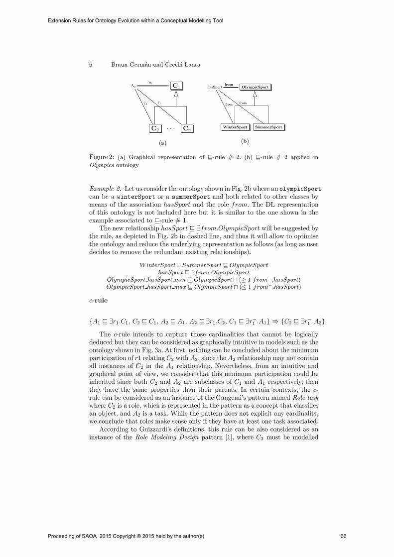
6 Braun German and Cecchi Laura
C1
C2 Cn
A1
r1
A1
r1
A1
r1
. . .
(a)
OlympicSport
WinterSport SummerSport
hasSport
from
hasSport
from
hasSportfrom
(b)
Figure 2: (a) Graphical representation of ⊑-rule # 2. (b) ⊑-rule # 2 applied in
Olympics ontology
Example 2. Let us consider the ontology shown in Fig. 2b where an olympicSportcan be a winterSport or a summerSport and both related to other classes bymeans of the association hasSport and the role from. The DL representationof this ontology is not included here but it is similar to the one shown in theexample associated to ⊑-rule # 1.
The new relationship hasSport ⊑ ∃from.OlympicSport will be suggested bythe rule, as depicted in Fig. 2b in dashed line, and thus it will allow to optimisethe ontology and reduce the underlying representation as follows (as long as userdecides to remove the redundant existing relationships).
WinterSport⊔ SummerSport ⊑ OlympicSport
hasSport ⊑ ∃from.OlympicSport
OlympicSport hasSport min ⊑ OlympicSport ⊓ (≥ 1 from−.hasSport)OlympicSport hasSport max ⊑ OlympicSport ⊓ (≤ 1 from−.hasSport)
c-rule
A1 ⊑ ∃r1.C1, C2 ⊑ C1, A2 ⊑ A1, A2 ⊑ ∃r1.C2, C1 ⊑ ∃r−1.A1 C2 ⊑ ∃r−
1.A2
The c-rule intends to capture those cardinalities that cannot be logicallydeduced but they can be considered as graphically intuitive in models such as theontology shown in Fig. 3a. At first, nothing can be concluded about the minimumparticipation of r1 relating C2 with A2, since the A2 relationship may not containall instances of C2 in the A1 relationship. Nevertheless, from an intuitive andgraphical point of view, we consider that this minimum participation could beinherited since both C2 and A2 are subclasses of C1 and A1 respectively, thenthey have the same properties than their parents. In certain contexts, the c-rule can be considered as an instance of the Gangemi’s pattern named Role task
where C2 is a role, which is represented in the pattern as a concept that classifiesan object, and A2 is a task. While the pattern does not explicit any cardinality,we conclude that roles make sense only if they have at least one task associated.
According to Guizzardi’s definitions, this rule can be also considered as aninstance of the Role Modeling Design pattern [1], where C2 must be modelled
Proceeding of SAOA 2015 Copyright © 2015 held by the author(s) 66
Extension Rules for Ontology Evolution within a Conceptual Modelling Tool
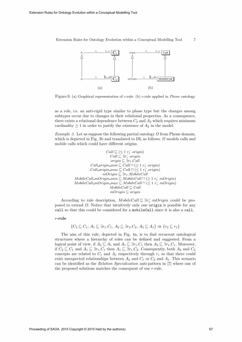
Extension Rules for Ontology Evolution within a Conceptual Modelling Tool 7
C1
C2
A1
r1 1..n
A2
r1 1..n
(a)
Call
MobileCall
originr1 1..n
mOriginr1 1..n
(b)
Figure 3: (a) Graphical representation of c-rule. (b) c-rule applied in Phone ontology
as a role, i.e. an anti-rigid type similar to phase type but the changes amongsubtypes occur due to changes in their relational properties. As a consequence,there exists a relational dependence between C2 and A2 which requires minimumcardinality ≥ 1 in order to justify the existence of A2 in the model.
Example 3. Let us suppose the following partial ontology Ω from Phone domain,which is depicted in Fig. 3b and translated to DL as follows. Ω models calls andmobile calls which could have different origins.
Call ⊑ (≤ 1 r−1.origin)
Call ⊑ ∃r−1.origin
origin ⊑ ∃r1.Call
Call origin min ⊑ Call ⊓ (≥ 1 r−1.origin)
Call origin max ⊑ Call ⊓ (≤ 1 r−1.origin)
mOrigin ⊑ ∃r1.MobileCall
MobileCall mOrigin min ⊑ MobileCall ⊓ (≥ 1 r−1.mOrigin)
MobileCall mOrigin max ⊑ MobileCall ⊓ (≤ 1 r−1.mOrigin)
MobileCall ⊑ Call
mOrigin ⊑ origin
According to rule description, MobileCall ⊑ ∃r−1.mOrigin could be pro-
posed to extend Ω. Notice that intuitively only one origin is possible for anycall so that this could be considered for a mobileCall since it is also a call.
r-rule
C2 ⊑ C1, A1 ⊑ ∃r1.C1, A2 ⊑ ∃r2.C2, A2 ⊑ A1 r2 ⊑ r1
The aim of this rule, depicted in Fig. 4a, is to find recurrent ontologicalstructures where a hierarchy of roles can be defined and suggested. From alogical point of view, if A2 ⊑ A1 and A1 ⊑ ∃r1.C1 then A2 ⊑ ∃r1.C1. Moreover,if C2 ⊑ C1 and A1 ⊑ ∃r1.C1 then A1 ⊑ ∃r1.C2. Consequently, both A2 and C2
concepts are related to C1 and A1 respectively through r1 so that there couldexist unexpected relationships between A2 and C1 or C2 and A1. This scenariocan be identified as the Relation Specialization anti-pattern in [7] where one ofthe proposed solutions matches the consequent of our r-rule.
Proceeding of SAOA 2015 Copyright © 2015 held by the author(s) 67
Extension Rules for Ontology Evolution within a Conceptual Modelling Tool
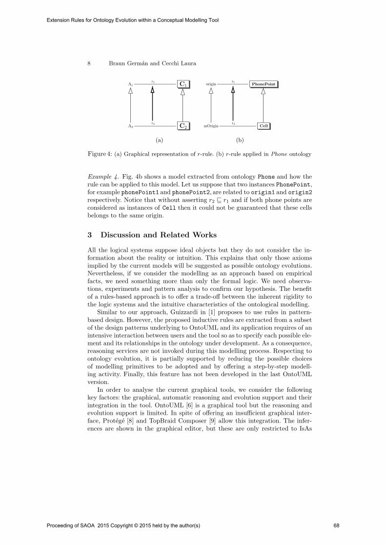
8 Braun German and Cecchi Laura
C1
C2
A1
r1
A2
r2
(a)
PhonePoint
Cell
originr1
mOriginr2
(b)
Figure 4: (a) Graphical representation of r-rule. (b) r-rule applied in Phone ontology
Example 4. Fig. 4b shows a model extracted from ontology Phone and how therule can be applied to this model. Let us suppose that two instances PhonePoint,for example phonePoint1 and phonePoint2, are related to origin1 and origin2
respectively. Notice that without asserting r2 ⊑ r1 and if both phone points areconsidered as instances of Cell then it could not be guaranteed that these cellsbelongs to the same origin.
3 Discussion and Related Works
All the logical systems suppose ideal objects but they do not consider the in-formation about the reality or intuition. This explains that only those axiomsimplied by the current models will be suggested as possible ontology evolutions.Nevertheless, if we consider the modelling as an approach based on empiricalfacts, we need something more than only the formal logic. We need observa-tions, experiments and pattern analysis to confirm our hypothesis. The benefitof a rules-based approach is to offer a trade-off between the inherent rigidity tothe logic systems and the intuitive characteristics of the ontological modelling.
Similar to our approach, Guizzardi in [1] proposes to use rules in pattern-based design. However, the proposed inductive rules are extracted from a subsetof the design patterns underlying to OntoUML and its application requires of anintensive interaction between users and the tool so as to specify each possible ele-ment and its relationships in the ontology under development. As a consequence,reasoning services are not invoked during this modelling process. Respecting toontology evolution, it is partially supported by reducing the possible choicesof modelling primitives to be adopted and by offering a step-by-step modell-ing activity. Finally, this feature has not been developed in the last OntoUMLversion.
In order to analyse the current graphical tools, we consider the followingkey factors: the graphical, automatic reasoning and evolution support and theirintegration in the tool. OntoUML [6] is a graphical tool but the reasoning andevolution support is limited. In spite of offering an insufficient graphical inter-face, Protege [8] and TopBraid Composer [9] allow this integration. The infer-ences are shown in the graphical editor, but these are only restricted to IsAs
Proceeding of SAOA 2015 Copyright © 2015 held by the author(s) 68
Extension Rules for Ontology Evolution within a Conceptual Modelling Tool

Extension Rules for Ontology Evolution within a Conceptual Modelling Tool 9
hierarchies. Their evolution support is also partial: manual, ontology differences(Protege) and versioning and collaboration (TopBraid Composer). Finally, NeOntoolkit [10], Kaon2 [11] and SWOOP [12] provide access to reasoners but theyare not graphical-based tools. Respecting to evolution, only NeOn incorporatesa specific framework to support it from external sources. Kaon2 and SWOOPsimply offer some operations as redo and undo (Kaon2) or imports and versioning(SWOOP). Other tools as GrOWL [13], OWLGrEd [14], Graphol [15], “modeloutline” framework [16] and VOWL [17], which is a Protege plugin, are alsographical-centered tool. They define a graphical syntax and semantics providingusers with a visual representation of their models and thus avoid any complextextual syntax. Nevertheless, the reasoning support is not provided in any ofthese tools as ICOM does and the ontology evolution is not properly supported.
The intention behind rules is to reduce the complexity of the evolution processand they are defined to be implemented within a graphical tool. Nevertheless,they cannot be isolated from other complementary artefacts such as user querieswhich allow to identify relevant parts of an ontology and back-end reasoningsystems which allow to inquire the model to check rules applicability and theirpossible consequences. In any case, it is the user who decides which of the sug-gestions (rule consequences) are appropriate, if any, according to his intendedmodel.
4 Conclusions and Future Works
This work introduces a small catalogue of extension rules which intends to cap-ture the intuitive characteristics inherent to the ontology modelling. Each rulehas been defined and analysed by considering different theories of design patternsand by showing the intended meaning through illustrations where the intuitionis presented. The aim is to place emphasis on a reduced search space of possibleontology extensions, and thus also reduce the complexity when trying with largeontologies. This alternative offers flexibility and a fine-grained level where thefocus is on a subset of ontology elements to analyse in order to introduce newones, in contrast to design patterns which are not orientated towards ontologyevolution since its smallest unit of work is an ontology when in rules it is anontological element. Then they have the effect of changing only the ontologyelements involved in the refactoring, which can be intra- or inter-ontology ones.Rules must be used together with other artefacts such as user queries and back-end reasoning systems to identify relevant parts of an ontology and check theconsequences of application on the whole model. Furthermore, the modularity isa key property in this approach so that some changes on the set of rules are in-dependent of the underlying methodology. An example about the usage of theserules in a methodology has been published in [18].
As future works, we propose to identify new extension rules and define alogical formalism as an application framework for these rules. The rules willbe also evaluated by means of two techniques such as a behaviour-based one,which will allow us to register the number of suggestions accepted by user, and
Proceeding of SAOA 2015 Copyright © 2015 held by the author(s) 69
Extension Rules for Ontology Evolution within a Conceptual Modelling Tool

10 Braun German and Cecchi Laura
an opinion-based one, which will enable us to elicit users opinions about theuse of them [19]. We plan to provide support to user-defined rules and to rulesinvolving instances so that we could supply evolution at extensional level (ABox)and possibly use it to extend the intentional knowledge.
References
1. Guizzardi, G., das Gracas, A., Guizzardi, R.: Design patterns and inductive mod-eling rules to support the construction of ontologically well-founded conceptualmodels in ontouml. In: CAiSE Workshops. (2011)
2. Gangemi, A., Presutti, V.: Ontology design patterns. In: Handbook of Ontologies.2nd edn. (2009)
3. Franconi, E., Ng, G.: The i.com tool for intelligent conceptual modelling. In: Proc.of 7th KRDB’2000. (2000)
4. Fillottrani, P., Franconi, E., Tessaris, S.: The new icom ontology editor. In: De-scription Logics. CEUR Workshop Proceedings, CEUR-WS.org (2006)
5. Fillottrani, P., Franconi, E., Tessaris, S.: The icom 3.0 intelligent conceptualmodelling tool and methodology. Semantic Web (2012)
6. Guizzardi, G.: Ontological foundations for structural conceptual models. PhDthesis, University of Twente, Enschede, The Netherlands, Enschede (October 2005)
7. Guizzardi, G., Sales, T.P.: Detection, simulation and elimination of semantic anti-patterns in ontology-driven conceptual models. In: Conceptual Modeling - 33rdInternational Conference, ER 2014. Proceedings. (2014)
8. Knublauch, H., Fergerson, R., Noy, N., Musen, M.: The protege owl plugin: Anopen development environment for semantic web applications. (2004)
9. TopQuadrant: TopQuadrant — Products — TopBraid Composer (2011)10. Hasse, P., Lewen, H., Studer, R., Erdmann, M.: The NeOn Ontology Engineering
Toolkit. (2008)11. Motik, B., Studer, R.: KAON2–A Scalable Reasoning Tool for the Semantic Web.
In: Proceedings of the 2nd ESWC’05. (2005)12. Kalyanput, A., Parsia, B., Sirin, E., Grau, B., Hendler, J.: Swoop: A ’web’ ontology
editing browser. Journal of Web Semantics (June 2005)13. Krivov, S., Williams, R., Villa, F.: Growl: A tool for visualization and editing of
owl ontologies. J. Web Sem. (2007)14. Cerans, K., Ovcinnikova, J., Liepins, R., Sprogis, A.: Advanced owl 2.0 ontol-
ogy visualization in owlgred. In: DB&IS. Frontiers in Artificial Intelligence andApplications, IOS Press (2012)
15. Console, M., Lembo, D., Santarelli, V., Savo, D.F.: Graphol: Ontology repres-entation through diagrams. In: Informal Proceedings of the 27th InternationalWorkshop on Description Logics. (2014)
16. do Amaral, F.N.: Usability of a visual language for dl concept descriptions. In:RR. Lecture Notes in Computer Science, Springer (2010)
17. Lohmann, S., Negru, S., Bold, D.: The protegevowl plugin: Ontology visualizationfor everyone. In: The Semantic Web: ESWC 2014 Satellite Events. Lecture Notesin Computer Science. (2014)
18. Braun, G., Cecchi, L., Fillottrani, P.: Integrating Graphical Support with Reason-ing in a Methodology for Ontology Evolution. In: Proc. of the 9th Int. Workshopon Modular Ontologies WoMO 15 IJCAI 15. CEUR Workshop Proceedings (2015)
19. Gediga, G., Hamborg, K.C.: Evaluation of software systems. Encyclopedia ofComputer Science and Technology (2001)
Proceeding of SAOA 2015 Copyright © 2015 held by the author(s) 70
Extension Rules for Ontology Evolution within a Conceptual Modelling Tool

Metodo Practico para la Poblacion yPersistencia de un Modelo Semantico
Jose A. Gilliard1, Omar R. Perın1, Mariela Rico1, and Ma. Laura Caliusco1,2
1 Centro de Investigacion y Desarrollo de Ingenierıa en Sistemas de Informacion(CIDISI) - UTN - Fac. Regional Santa Fe, Lavaise 610 - S3004EWB - Santa Fe
[email protected] Consejo Nacional de Investigaciones Cientıficas y Tecnicas (CONICET)
Resumen Actualmente, cada vez son mas los gobiernos que publicansus datos siguiendo la doctrina de Gobierno Abierto. Si bien existenvarias propuestas de como realizar dicha publicacion, ninguna de ellases completa y, por lo tanto, no pueden ser facilmente replicadas. En estetrabajo se presenta una estrategia para el poblado y persistencia de datosbasados en un modelo semantico utilizando el lenguaje de mapeo D2RQy el Triple Store Jena TDB.
Keywords: modelo semantico, datos abiertos, D2RQ, Jena TDB
1. Introduccion
Hoy en dıa, la publicacion de datos ha tomado importancia, siendo esta, junto conla busqueda de informacion, los objetivos principales de Internet. Si se relacionanlos datos y ademas se les agrega interpretacion, entonces se puede hablar no solode la publicacion de informacion sino tambien de conocimiento [9].
Por otro lado, ha surgido un nuevo modelo de gobierno llamado GobiernoAbierto, el cual se basa en la premisa de que todos los datos que produce el go-bierno son publicos [1]. Un Gobierno Abierto es aquel que entabla una constanteconversacion con los ciudadanos con el fin de oır lo que ellos dicen y solicitan,que toma decisiones basadas en sus necesidades y preferencias, que facilita lacolaboracion de los ciudadanos y funcionarios en el desarrollo de los serviciosque presta, y que comunica todo lo que hace de forma abierta y transparente[2]. Existen varias iniciativas de Gobierno Abierto que difieren en la estrategiaseguida: mientras unas iniciativas, como la de Estados Unidos, se centraron enla publicacion de la mayor cantidad de informacion en el menor plazo posible,volcando la informacion en crudo tal y como estaba disponible, otras, como elcaso de Gran Bretana y Espana, realizaron un tratamiento previo de los datosempleando tecnologıas de la Web Semantica para modelar la informacion y es-tablecer relaciones explıcitas entre los distintos conjuntos de datos, siguiendo losprincipios de Datos Enlazados [5]:
- Utilizar URIs (Uniform Resource Identifier) como nombres unicos para losrecursos.
Proceeding of SAOA 2015 Copyright © 2015 held by the author(s) 71

- Incluir enlaces a otras URIs para localizar mas Datos Enlazados.- Utilizar el protocolo HTTP (HyperText Transfer Protocol) para nombrar y
resolver la ubicacion de los datos identificados mediante esas URIs.- Representar los datos en RDF3 y utilizar SPARQL4, un lenguaje de consulta
para RDF, como lenguaje de consulta de dichos datos.
En este ultimo sentido existen diferentes arquitecturas y metodologıas ba-sadas en modelos semanticos compuestos por ontologıas. Por ejemplo, en [8] sepresenta un proceso para publicar datos enlazados de gobierno, pero cuando sequiere llevar a la practica dicho proceso se carece de instrucciones detalladassobre como hacerlo. El trabajo presentado en [7] se centra principalmente en eldesarrollo de la ontologıa en un contexto de datos enlazados y en la evaluaciondel producto obtenido segun criterios de la Ingenierıa Ontologica y los principiosde Datos Enlazados, pero no se explicitan reglas claras para el poblado de estaontologıa. En [5] se presenta un framework de alto nivel para la publicacion dedatos basados en los principios de Datos Enlazados pero no se describe comoaplicarlo. Estos inconvenientes hacen difıcil replicar estas propuestas en otroscasos, sobre todo cuando se deben manejar grandes volumenes de datos pro-venientes de distintas fuentes de informacion y no existe una correspondenciadirecta entre los elementos de estas fuentes y los de las ontologıas.
El objetivo de este trabajo es presentar una estrategia que permita la per-sistencia y poblacion de grandes ontologıas para dar soporte a aplicaciones deDatos Abiertos siguiendo los principios de Datos Enlazados. Dicha estrategia sedefinio luego de realizar varias iteraciones, siguiendo los lineamientos del metodoInvestigacion en Accion [10].
2. Pasos para Poblar y Persistir un Modelo Semantico
En esta seccion se presentan los pasos de una estrategia para la poblacion ypersistencia de un modelo semantico que sera utilizado para la publicacion dedatos de gobierno. El objetivo de dicha estrategia es generar las tripletas ne-cesarias para poblar las ontologıas del modelo semantico a partir de los datosalmacenados en una base de datos (BD), cumpliendo con los requerimientos es-pecificados en el Documento de Especificacion de Requerimientos del ModeloSemantico (DERMS) que se desea poblar y las correspondencias entre los datosen las tablas de las BD y los elementos del modelo. Dichas correspondencias seencuentran especificadas en el Documento de Correspondencias entre la BD ylas Ontologıas (DCBDO) que se debe recibir como entrada.
Se considera como caso de estudio, para presentar la estrategia, la poblaciony persistencia del modelo semantico del personal del Gobierno de la Provinciade Santa Fe [6]. Se recibieron como entrada el DERMS, el DCBDO, el modelosemantico implementado en el lenguaje OWL y la BD de la cual se debıan extraerlos datos. El modelo semantico recibido como entrada esta compuesto por cuatroontologıas modulares: Lugares, Cargos, Organismos y Agentes.
3 http://www.w3.org/TR/2014/REC-rdf11-concepts-20140225/4 http://www.w3.org/TR/2013/REC-sparql11-query-20130321/
Proceeding of SAOA 2015 Copyright © 2015 held by the author(s) 72
Método Práctico para la Población y Persistencia de un Modelo Semántico

Figura 1. Diagrama entidad-relacion simplificado para poblar la ontologıa Lugares
2.1. Analisis de las Fuentes de Informacion
Los objetivos de este paso son: (1) preparar las BDs origen para la extraccionde los datos para generar las tripletas necesarias para poblar el modelo, y (2)analizar el modelo semantico para comprenderlo y definir las URLs a usar.
Analizar las fuentes de informacion. La informacion primaria se encuentraen una BD ORACLE de gran porte. Para independizar esta fuente de la publi-cacion de datos, se hizo una replica de la informacion a publicar en una BD decodigo abierto, MySQL, denominada “personto” (dicha BD cuenta con 47 tablasy un total de 7.439.605 registros) y se creo un archivo de texto plano conteniendolas sentencias SQL necesarias para la creacion de las tablas y posterior carga delos datos. Para disponer de una BD operativa fue necesario montar un servidorde BD en los equipos de desarrollo, y configurar y poner en marcha el servicio.
Dado que no todas las tablas de la BD se usaron para la generacion de triple-tas, resulto de gran utilidad hacer diagramas de entidad-relacion simplificadospara cada una de las ontologıas del modelo en los que solo se desplegaron aque-llas tablas que intervendrıan en su poblacion. Esta fragmentacion surgio de losrequerimientos definidos en el DERMS. A manera de ejemplo, se muestra en laFigura 1 el diagrama de tablas de Lugares que luego se utilizara en los ejemplos.
Preparar los datos para generar las tripletas. Para poder generar lastripletas fue necesario realizar las siguientes tareas sobre los datos de la BD:
Tarea 1: Anonimizar datos. Con el fin de no hacer referencia a personas reales, sereemplazaron sus nombres y apellidos por datos ficticios para lo cual se creo unarutina en lenguaje Java y se la ejecuto sobre la BD “personto”.
Tarea 2: Tratar valores especiales. Un aspecto importante a tener en cuenta esla existencia de valores nulos (NULL) en la BD. En algunos casos un valor nuloen un campo de una tabla significa ausencia o desconocimiento del dato. Porejemplo, el campo que almacena el numero de telefono de una persona.
Proceeding of SAOA 2015 Copyright © 2015 held by the author(s) 73
Método Práctico para la Población y Persistencia de un Modelo Semántico
En otros casos, al momento de elaborar el modelo semantico se le dio unsignificado especıfico a ese valor nulo. Por ejemplo, el modelo semantico estudiadodefine la propiedad funcionamiento para la clase OrganismoEnSARH, que seorigina a partir del campo CLAUSURA de la tabla organismos. Los valoresalmacenados en este campo son los caracteres S y T, que se traducen a losvalores En Funcionamiento y Cerrado Temporalmente de la propiedad para lasinstancias de la clase. El modelo semantico, ademas de esta interpretacion de losdatos, agrega un tercer posible valor Cerrado que debera utilizarse para los casosen que el valor del campo CLAUSURA sea NULL. Las herramientas adoptadasno dan soporte para este tipo de transformacion con valores nulos, por lo que fuenecesario modificar una serie de registros en la BD para incluir un nuevo valoral campo CLAUSURA en aquellos registros donde era nulo.
Definir una URL base para el modelo semantico y, en base a esta,una URL para cada ontologıa del modelo. Para publicar datos en la Web,los elementos de un dominio de interes primero deben ser identificados[5]. DatosEnlazados utiliza solo URIs HTTP por dos razones:
1. proporcionan una forma sencilla de crear nombres unicos globales de maneradescentralizada
2. y sirven como medio de acceso a la informacion que describe la entidadidentificada.
La URL http://www.frsf.utn.edu.ar/personto/ identifica globalmente al mo-delo semantico estudiado. Las demas URL definidas son las siguientes:
- Agentes: http://www.frsf.utn.edu.ar/personto/ontoagentes#- Cargos: http://www.frsf.utn.edu.ar/personto/ontocargos#- Lugares: http://www.frsf.utn.edu.ar/personto/ontolugares#- Organismos http://www.frsf.utn.edu.ar/personto/ontoorganismos#
Definir las colecciones para las instancias de cada ontologıa y sus res-pectivas URLs. Cada clase definida en un modelo semantico da origen a unaserie de recursos, sus instancias. Los recursos de una misma clase se agrupanen una coleccion. Para identificar estos recursos es necesario adoptar un crite-rio respecto de los nombres a asignar a las colecciones y, ademas, construir unacadena de texto que identifique de manera unıvoca a cada recurso.
Para la nominacion de colecciones se utilizo el plural del sustantivo que danombre a la clase a la cual corresponden los recursos. Ası, por ejemplo, lasinstancias de la clase Provincia se agruparon dentro de la coleccion provincias.
Para generar los identificadores se usaron los valores correspondientes a lasclaves primarias de las tablas desde las cuales se extraen los datos, asegurandoası su unicidad. En los casos donde la clave primaria estaba compuesta por masde un campo, se concatenaron sus valores.
La estructura de la URI correspondiente a cualquier recurso del modelo es:<http://www.frsf.utn.edu.ar/personto/coleccion/id recurso>
Proceeding of SAOA 2015 Copyright © 2015 held by the author(s) 74
Método Práctico para la Población y Persistencia de un Modelo Semántico

Algunos ejemplos de las correspondencias entre cada clase del modelo y laURI de la coleccion en la cual se agrupan sus instancias son:
- Pais: http://www.frsf.utn.edu.ar/personto/paises/- Departamento: http://www.frsf.utn.edu.ar/personto/departamentos/- Provincia: http://www.frsf.utn.edu.ar/personto/provincias/
2.2. Poblacion del Modelo Semantico
Cada elemento de la ontologıa tendra una correspondencia, directa o no, con ele-mentos de las BDs. A partir de las BDs y en base a las definiciones establecidasen las ontologıas, primero se deben establecer las correspondencias que permi-tan generar las tripletas necesarias para representar las definiciones de clases,instancias y sus propiedades, y las relaciones entre las instancias de esas clases.Estas tripletas convierten la ontologıa modelada en una ontologıa poblada.
Para cada ontologıa, identificar grupos de tripletas a generar. Estaactividad consiste en identificar que grupos de tripletas se deben generar segunlos elementos que componen la ontologıa dada. Para cada ontologıa, se necesitantripletas para la declaracion e instanciacion de cada una de sus elementos.
Definir los patrones que seguiran las componentes sujeto, propiedad yobjeto de las tripletas de cada grupo. Partiendo de los grupos establecidosen la actividad anterior se procedio a especificar de que manera debıan estarcompuestas las tripletas para cada grupo.
Declaracion de clases. Para la declaracion de clases se debe generar una triple-ta que identifique a la clase como tal y dos tripletas opcionales para agregarcomentarios y etiquetas, siguiendo los patrones que se muestran a continuacion:
<URI CLASE><http://www.w3.org/1999/02/22-rdf-syntax-ns#type><http://www.w3.org/2000/01/rdf-schema#Class>.<URI CLASE><http://www.w3.org/2000/01/rdf-schema#label>“ETIQUETA” .<URI PROPIEDAD><http://www.w3.org/2000/01/rdf-schema#comment>“COMENTARIO” .
Cuando existe herencia de clases, para cada una de las subclases se debeincluir una tripleta extra indicando la relacion, como se muestra a continuacin:
<URI SUBCLASE><http://www.w3.org/2000/01/rdf-schema#subClassOf><URI SUPERCLASE>.
Instanciacion de clases Por cada instancia de clase se debe generar una tripletasegun el siguiente patron:
<URI INSTANCIA><http://www.w3.org/1999/02/22-rdf-syntax-ns#type><URI CLASE>.
Proceeding of SAOA 2015 Copyright © 2015 held by the author(s) 75
Método Práctico para la Población y Persistencia de un Modelo Semántico
Declaracion de propiedades de instancias. Las propiedades se declaran con unatripleta que identifique la propiedad como tal y, opcionalmente, dos o mas paraagregar comentarios y etiquetas, con los patrones que se muestran a continuacion.
<URI PROPIEDAD><http://www.w3.org/1999/02/22-rdf-syntax-ns#type><http://www.w3.org/1999/02/22-rdf-syntax-ns#Property>.<URI PROPIEDAD><http://www.w3.org/2000/01/rdf-schema#label>“ETIQUETA” .<URI PROPIEDAD><http://www.w3.org/2000/01/rdf-schema#comment>“COMENTARIO” .
En los casos en que el dominio de la propiedad esta integrado por mas de unaclase, se genera una unica tripleta para identificar a la propiedad, las tripletasde etiqueta y comentario para cada clase incluida en el dominio.
Instanciacion de propiedades de instancias. Se debe generar una tripleta porcada propiedad de cada instancia de cada clase siguiendo el siguiente patron:
<URI INSTANCIA><URI PROPIEDAD>“VALOR PROPIEDAD” .
Declaracion de relaciones entre instancias. Se debe generar una tripleta queidentifique cada relacion como tal y, opcionalmente, dos o mas para agregarcomentarios y etiquetas. Los patrones para estas tripletas son:
<URI RELACION><http://www.w3.org/1999/02/22-rdf-syntax-ns#type><http://www.w3.org/1999/02/22-rdf-syntax-ns#Property>.<URI RELACION><http://www.w3.org/2000/01/rdf-schema#label>“ETIQUETA” .<URI RELACION><http://www.w3.org/2000/01/rdf-schema#comment>“COMENTARIO” .
Instanciacion de relaciones entre instancias. Se debe generar una tripleta porcada par de instancias relacionadas segun el siguiente patron:
<URI INSTANCIA SUJETO><URI RELACION><URI INSTANCIA OBJETO>.
Calcular la cantidad de tripletas a generar para cada grupo en basea consultas SQL a las BD de origen. Se debe obtener, para cada grupode tripletas y teniendo en cuenta los patrones necesarios para cada grupo, lacantidad exacta de tripletas que se deben generar para la declaracion de todas lasclases y propiedades del modelo semantico y la extraccion de todas las instanciasalmacenadas en las BDs. Para estos calculos se debe tener en cuenta lo siguiente:
- cada subclase en una relacion de herencia requiere una tripleta adicional;- la instanciacion de una propiedad de una clase depende de la cantidad de
valores no nulos en el campo origen de dicha propiedad;- las propiedades con n clases en su dominio (n ≥ 2) requieren 3 + 2× (n− 1)
tripletas
Para cada ontologıa, redactar un archivo de mapeo D2RQ que permitagenerar los lotes correspondientes de forma automatizada. Mediante eluso de un lenguaje especıfico, D2RQ Mapping Language, se pueden escribir blo-ques de codigo que establecen la asociacion entre los campos de las tablas en lasBDs y los elementos definidos en las ontologıas, como clases y propiedades [4]. El
Proceeding of SAOA 2015 Copyright © 2015 held by the author(s) 76
Método Práctico para la Población y Persistencia de un Modelo Semántico

contenido base de un archivo de mapeo D2RQ consiste en la definicion de prefijos,conexiones a BDs, bloques d2rq:ClassMap, uno por cada clase de la ontologıa,y bloques d2rq:PropertyBridge para generar propiedades entre las instancias delas clases. A continuacion se detallan cada uno de ellos.
Declaracion de prefijos. Los archivos de mapeo comienzan con la declaracion delos prefijos necesarios, incluyendo uno para la URI base del modelo, uno paracada URI de las diferentes ontologıas que lo forman y uno para cada coleccionde instancias. Tambien, se deben incluir una serie de prefijos de espacios denombres de uso comun, como el de D2RQ y OWL. No es necesario incluir todoslos prefijos especıficos del modelo, sino solo aquellos que se utilizan localmente.
Conexion a BDs. Se deben establecer las conexiones a las BDs con las que se va atrabajar para la extraccion de tripletas. Para ello, un objeto d2rq:Database defineuna conexion JDBC a una BD relacional local o remota. Un archivo de mapeoD2RQ puede contener mas de un objeto d2rq:Database, permitiendo el acceso amultiples BDs diferentes. Una vez declarado este objeto, cualquier acceso a laBD se realizara haciendo referencia al mismo.
Mapeo de clases y sus instancias. D2RQ abarca las definiciones de clases y susinstancias con un solo bloque de codigo, a traves de un objeto d2rq:ClassMap. Porejemplo, el bloque de codigo siguiente realiza el mapeo entre la tabla paises y laclase Pais de la ontologıa Lugares, mediante la definicion del mapeo map:Paises.
map:Paises a d2rq:ClassMap; d2rq:dataStorage map:persontoDB; d2rq:uriPattern“paises/@@paises.COD PAIS—encode@@”; d2rq:class ontolugares:Pais; d2rq:classDefinitionLabel“Pais”; d2rq:classDefinitionComment “Representa el paıs de nacimiento de un Agente.”; .
Este mapeo da origen a las tripletas de definicion de la clase Pais, una etique-ta (d2rq:classDefinitionLabel) y comentario (d2rq:classDefinitionComment) parala misma. La propiedad d2rq:dataStorage especifica que el objeto obtendra datosde la BD definida anteriormente por el objeto map:persontoDB.
Cada registro de la tabla dara origen a una instancia de la clase, que es-tara identificada y sera posible acceder a la misma por medio de la URI com-puesta por el infijo paises/, correspondiente a la coleccion, seguido del codigodel paıs. Esto se logra haciendo uso de la propiedad d2rq:uriPattern. En tiempode ejecucion, a toda URI generada a partir de un mapeo D2RQ se le anade unprefijo global correspondiente a la URL base que identifica al modelo.
Mapeo de propiedades y sus instancias. El objeto D2RQ, que hace posible elmapeo de Data Properties y Object Properties es d2rq:PropertyBridge.
Una Data Property puede generarse de varias formas. El valor de la mismapuede obtenerse, por ejemplo, a partir de un valor simple de una columna de lamisma tabla desde la cual se origino la instancia, una columna de otra tabla, unpatron generado a partir de la concatenacion de varias columnas o una corres-pondencia entre valores enumerados. La definicion de un d2rq:PropertyBridgeesta compuesta por la especificacion del d2rq:ClassMap, que da origen a las ins-tancias a las cuales agrega propiedades mediante la propiedad d2rq:belongsToClassMap,
Proceeding of SAOA 2015 Copyright © 2015 held by the author(s) 77
Método Práctico para la Población y Persistencia de un Modelo Semántico

la propiedad RDF que esta generando, especificada por la propiedad d2rq:property,y el valor asignado.
Las Object Properties se extraen generalmente de alguna relacion entre tablasy se mapean generando un bloque de tipo d2rq: PropertyBridge con el agregadode una o mas propiedades d2rq:join, que fijen la relacion de igualdad entre cam-pos de tabla. Ademas, teniendo en cuenta la definicion de una object property co-mo una tripleta sujeto-propiedad-objeto, la propiedad d2rq:belongsToClassMapindica el mapeo que da origen a las instancias sujeto, mientras que d2rq:refersToClassMap indica las instancias objeto. Los signos < y > se utilizan para indi-car, mediante la punta de flecha, cual de los lados de la condicion de igualdadcorresponde a una clave primaria. Esto permite al motor D2RQ optimizar elmecanismo interno de resolucion de consultas SQL, reduciendo los tiempos deprocesamiento requeridos para la transformacion de los datos.
En ciertos casos, el valor que de una propiedad puede estar incluido en unaenumeracion de posibles valores, por lo cual el rango de la propiedad correspondea un tipo de datos enumerado. Pueden existir, ademas, casos en los que los valoresalmacenados en campos de tablas que dan origen a propiedades de instanciascontengan valores que por diseno del modelo semantico deban ser traducidos oconvertidos a otro formato al momento de la generacion de las tripletas. Paraestos casos se emplean caracterısticas particulares del lenguaje D2RQ.
Para cada ontologıa, generar un volcado de tripletas serializadas enformato n-triples. Una vez redactado el archivo de mapeo para cada ontologıa,se generan volcados de tripletas para cada mapeo. La herramienta dump-rdf dela plataforma D2RQ permite generar estos volcados de tripletas serializadas enformato n-triples. Se utiliza este formato por ser el mas adecuado para persistir,en el proceso siguiente, los lotes generados en un T-Store, ya que su procesa-miento requiere menores niveles de recursos de CPU y memoria.
Verificar si se generaron las cantidades de tripletas correctas. Las he-rramientas de lınea de comandos grep y wc5 permiten contar la cantidad delıneas en un archivo que contengan un patron de texto especificado. Dado quebajo el formato de serializacion n-triples cada lınea del archivo de volcado co-rresponde a una tripleta, si se define correctamente el patron de texto a buscarmediante el uso de expresiones regulares, se puede saber con exactitud la can-tidad de ocurrencias de un modelo de tripleta que responden a cada uno de losgrupos particulares que existen en el volcado.
2.3. Persistencia del Modelo Semantico
El objetivo es generar un repositorio persistente en el que se encuentre almace-nado el modelo semantico junto con las instancias generadas anteriormente, listopara ser consultado. Este proceso consta de las tres actividades siguientes.
5 http://manpages.ubuntu.com/
Proceeding of SAOA 2015 Copyright © 2015 held by the author(s) 78
Método Práctico para la Población y Persistencia de un Modelo Semántico
Crear un Triple Store. Para crear la Triple Store se selecciono la combinacionde las herramientas D2RQ y el Framework Jena. Para la seleccion de dichasherramientas se busco alcanzar el mayor grado de interoperabilidad entre ellas,teniendose en cuenta, ademas, la disponibilidad de documentacion y madurez delos proyectos de desarrollo correspondientes. De los dos repositorios ofrecidos porJena, SDB y TDB6, se eligio el segundo, debido a que SDB ya no se encuentraen desarrollo activo, y ademas presenta mayor eficiencia y escalabilidad.
Cargar al Store cada una de las ontologıas del modelo semantico. Lagestion del repositorio y el acceso al mismo pueden realizarse programaticamentemediante una serie de metodos ofrecidos por la API del framework Jena, o me-diante el uso de herramientas de lınea de comando provistas por la plataforma.Para la carga masiva de datos, la segunda alternativa resulta mas eficiente.
La herramienta de lınea de comandos tdbloader permite la carga masiva dearchivos RDF al almacen Jena TDB, y genera con cada carga los ındices ne-cesarios para optimizar el acceso a los datos. Se deben tener en cuenta dosrestricciones de esta herramienta. En primer lugar, las ontologıas a cargar debenencontrarse serializadas en formato RDF/XML. La segunda restriccion es quetdbloader no es transaccional, lo que implica el bloqueo del repositorio durantelas operaciones de carga, denegandose el acceso simultaneo desde otro proceso.
Cargar al Store cada uno de los lotes de tripletas generados. El procesode carga se lleva a cabo con la herramienta tdbloader, la cual primero realiza lacarga de tripletas al almacen para luego pasar a la fase de indexado.
2.4. Consulta al Modelo Semantico Persistido y Poblado
Para cada una de las preguntas de competencia planteadas en el DERO para elmodelo semantico estudiado[6], se realizo una traduccion a consultas en lenguajeSPARQL. El texto de cada consulta SPARQL se guardo en un archivo de textocon extension .sparql, para luego utilizarlo en la ejecucion de la consulta.
Finalmente, sobre el repositorio Jena TDB se ejecuto cada una de las con-sultas SPARQL. Esta tarea se puede llevar a cabo ejecutando la herramienta delınea de comandos tdb-query de la plataforma Jena TDB. Otra forma de resol-ver consultas SPARQL es utilizando el motor de ejecucion de consultas ARQmediante la API provista por el framework Jena. Este metodo brinda mayorflexibilidad, a costas de un mayor consumo de recursos y tiempos de respuesta.
3. Lecciones Aprendidas y Trabajos Futuros
En este trabajo se presento una estrategia para persistir y poblar grandes onto-logıas para dar soporte a aplicaciones de Datos Abiertos siguiendo los principios
6 https://jena.apache.org/documentation/tdb/
Proceeding of SAOA 2015 Copyright © 2015 held by the author(s) 79
Método Práctico para la Población y Persistencia de un Modelo Semántico
de Datos Enlazados. La misma se probo en dos tesis de maestrıa que requerıanla poblacion de ontologıas con datos almacenados en sistemas de gobierno. Deestas pruebas se pudo concluir que la estrategia es util cuando la BD origenesta compuesta por varias tablas y los mapeos entre los elementos de la BD ylos del modelo semantico no son directos. Cuando hay pocas tablas, con mu-chos registros, y la herramienta de ontology learning permite crear de formadirecta el modelo semantico y sus instancias, puede resultar mas adecuada unaherramienta como RDB2Onto [3].
La estrategia definida requiere contar con desarrolladores con conocimientosen tecnologıas semanticas y definir un gran numero de tripletas (en el caso pre-sentado se definieron mas de 50.000.000 de tripletas). Por ello, se desarrollo unprototipo de aplicacion que guıa en la implementacion de la estrategia definida,el cual estan fuera del alcance de este trabajo.
La estrategia propuesta esta basada en D2RQ y el T-Store Jena TDB, sinembargo podrıa extenderse a otros lenguajes y T-stores.
Otro tema para trabajo futuro es la actualizacion de datos. En los casosestudiados los mismos se modifican una vez al mes siendo necesario realizar lospasos definidos para actualizarlos. En otros casos, el tema de la actualizaciondebe reveerse.
Referencias
1. Brys, C., Montes, A.: Gobierno Electronico 3.0. Aplicaciones de la Web Semanticaa la Administracion Publica. In: Anales del SIE 2011, Simposio de Informatica enel Estado, pp. 15–30 (2011)
2. Calderon, C., Lorenzo, S.: Open Government: Gobierno Abierto. Algon Editores,Espana (2010)
3. Cerbah, F.,: Learning highly structured semantic repositories from relational data-bases: the RDBToOnto tool. In: Proc. 5th European semantic web conference onThe semantic web: research and applications, pp. 777–781 (2008)
4. Cyganiak, R., Bizer, C., Garbers, J., Maresch, O., Becker, C.: The D2RQ mappinglanguage, http://d2rq.org/d2rq-language (2012)
5. Heath, T., Bizer, C.: Linked Data: Evolving the Web into a Global Data Space.Morgan & Claypool, 1st ed. (2011)
6. Lozano, A.: Enfoque Basado en Ontologıas para Brindar Acceso a la Informacion delPersonal del Gobierno de la Provincia de Santa Fe. Tesis de Maestrıa, UniversidadTecnologica Nacional, Facultad Regional Santa Fe, Argentina (2013)
7. Poveda-Villalon, M.: A Reuse-based Lightweight Method for Developing LinkedData Ontologies and Vocabularies. In: Simperl, E., Cimiano, P., Polleres, A., Corcho,O., Presutti, V. (eds.) The Semantic Web: Research and Applications. LNCS, vol.7295, pp. 833–8379. Springer, Heidelberg (2012)
8. Villazon-Terrazas, B., Vilches-Blazquez, L., Corcho, O., Gomez-Perez, A.: Metho-dological Guidelines for Publishing Government Linked Data. In: Wood, D. (ed.)Linking Government Data, pp. 27–49. Springer New York (2011)
9. Zins, C.: Conceptual Approaches for Defining Data, Information, and Knowledge.J. Am. Soc. Inf. Sci. Technol. 58, 479–493 (2007)
10. Avison, D., Lau, F., Myers, M., Nielsen, P.: Action research. Commun. ACM 42,94–97 (1999)
Proceeding of SAOA 2015 Copyright © 2015 held by the author(s) 80
Método Práctico para la Población y Persistencia de un Modelo Semántico

Un Modelo Ontológico para elGobierno Electrónico
Carlos Roberto Brys1, José F. Aldana-Montes2, David Luis La Red Martinez3
1 Departamento de Informática, Facultad de Ciencias Económicas, Universidad Nacional de Misiones,
Av. Fernando Llamosas Km 7,5. Campus UNaM. N3304. Posadas. Misiones. Argentina
[email protected] Departamento de Lenguajes y Ciencias de la Computación, Universidad de Málaga,
Boulevard Louis Pasteur 35. Campus de Teatinos. 29071 Málaga, Españ[email protected]
3 Departamento de Informática, Facultad de Ciencias Exactas y Naturales y Agrimensura,Universidad Nacional del Nordeste,
9 de Julio 1449C3400. Corrientes. Argentina
Resumen. La toma de decisiones muchas veces requiere información que debesuministrarse con el formato de datos enriquecidos. Atender apropiadamenteestas nuevas exigencias hace necesario que las agencias gubernamentalesorquesten grandes cantidades de información de diversas fuentes y formatos,para ser suministrados eficientemente a través de los dispositivos habitualmenteutilizados por las personas, tales como computadoras, netbooks, tablets ysmartphones.Para superar estos problemas, se propone un modelo para la representaciónconceptual de las unidades de organización del Estado, vistos como entidadesgeoreferenciadas del Gobierno Electrónico, basado en ontologías diseñadasbajo los principios de los Datos Abiertos Vinculados, lo que permite laextracción automática de información a través de las máquinas, que apoya alproceso de tomas de decisiones gubernamentales y da a los ciudadanos unacceso integral para encontrar y hacer trámites a través de las tecnologíasmóviles.
Palabras clave: Web de datos, Gobierno Electrónico, Administración Pública,Web Semántica, Datos Vinculados, Datos Abiertos del Gobierno, ExtracciónAutomática de Datos
Proceeding of SAOA 2015 Copyright © 2015 held by the author(s) 81
1 Introducción
La ventaja de expresar la estructura organizativa del Estado como una ontologíagobierno electrónico, es que se puede construir un modelo de información quepermita la exploración de datos en función de los elementos que representan lasasociaciones entre los objetos, las propiedades de los elementos y formalmentedescribir la semántica de la clases y propiedades utilizadas en relación dedependencia, temporal y espacial; facilitando así que se pueda realizar unrazonamiento automatizado, la búsqueda semántica y conceptual, y proporcionarservicios a los sistemas de apoyo a las decisiones.
El modelo presentado, incluye el diseño de una ontología para el GobiernoElectrónico de la Provincia de Misiones en Argentina, utilizando el Lenguaje deOntologías Web (OWL)1 como resultado de un proyecto de investigación en laUniversidad Nacional de Misiones con el gobierno provincial.
2. Trabajos Relacionados
En 2004 el proyecto OntoGov desarrolló una plataforma semánticamenteenriquecida con que aliviaría la composición coherente, la reconfiguración yevolución de los servicios de administración electrónica. El objetivo del proyectoOntoGov fue definir una ontología genérica de alto nivel para el ciclo de vida deservicio de Gobierno Electrónico, que serviría de base para el diseño de ontologías dedominio de nivel inferior específicos a los servicios públicos; desarrollar unaplataforma semánticamente enriquecida que permita a las administraciones públicasmodelar la semántica y las formalidades de sus servicios de administraciónelectrónica [16].
Al mismo tiempo, Vassilakis y Lepouras [17] propusieron una ontología para losservicios públicos del gobierno electrónico donde introdujeron una primeraaproximación de la modelación de una ontología para el Gobierno Electrónico, sobrela base de la organización, la legislación, la responsabilidad administrativa y deservicios.
Con el fin de estructurar el campo de la administración electrónica, los términos yla vinculación de los proyectos a través del uso de las tecnologías semánticas, en elInstituto de Informática en la Empresa y Gobierno (IWV) en la Universidad de Linz,
1 El Lenguaje de Ontologías Web (OWL) es una familia de lenguajes de representación del conoci-miento, para publicar y compartir datos usando ontologías en la WWW.
Proceeding of SAOA 2015 Copyright © 2015 held by the author(s) 82
Un Modelo Ontológico para el Gobierno Electrónico
se creó el proyecto del Portal Inteligente de Gobierno Electrónico. El resultado de estetrabajo es una ontología de conocimiento y un mapa de gobierno electrónico [12].
Las “Ontologías para el eGovernment” (oeGOV), un proyecto desarrollado porTopQuadrant y dirigido por Ralph Hodgson, fue un trabajo pionero en la creación deuna ontología para el gobierno electrónico [9]. El punto de partida del proyecto fue unmodelado de las agencias de Estados Unidos y su estructura. Como resultado de laobra, se crearon y publicaron en el sitio web www.oegov.org una serie de ontologíasfundacionales para el gobierno electrónico de Estados Unidos.
Para resolver los problemas de representación, Lacasta-Miguel [11] amplió unmodelo de ontologías en tres niveles: una ontología de nivel superior que define lostipos de datos y las relaciones generales independientes del contexto. Una ontologíade dominio donde los conceptos y relaciones reutilizables se definen en el contexto delos modelos administrativos de diferentes países; y una ontología de aplicación, dondeestán representados los tipos específicos de las unidades administrativas de cada país,junto con casos específicos de las unidades existentes.
Más enfocados en los servicios de gobierno electrónico, Hreño [10] y Ouchetto[13] plantearon el acceso, la recuperación y la integración de servicios utilizandoontologías. Considerando que la terminología relacionada con el campo de laadministración electrónica es variada, proponen dividir la ontología en las sub-ontologías (ontologías sectoriales). Para resolver la complejidad de la modelizaciónconceptual en escenarios complejos basados en la interoperabilidad semántica [2]proponen un método mediante el uso de ontologías de dominio y donde las fuentes deinformación son bases de datos, documentos legales y las personas.
3. Marco Teórico
Vamos a utilizar el término "Estado" como definición de un concepto político quese refiere a una forma de organización social y políticamente soberana, formada porun grupo de instituciones. Estas instituciones se estructuran funcionalmente enunidades administrativas, que son los elementos básicos de las estructurasorganizativas. En general, la organización de un Estado se distingue por: Funciones,Instituciones y Autoridades. El alto grado de diversidad y especialización de lasunidades administrativas demandan un modelo coherente para facilitar su gestión ysimplificar el uso [11].
Proceeding of SAOA 2015 Copyright © 2015 held by the author(s) 83
Un Modelo Ontológico para el Gobierno Electrónico
3.1. Datos Abiertos Vinculados del Gobierno (LGOD)
Tim Berners Lee esbozó un conjunto de normas para la publicación de datos en laWeb, de forma que todos los datos publicados se convierten en parte de un espacioúnico de datos globales [1]. Estos son conocidos como los “Principios de los DatosVinculados”. Datos Vinculados (Linked Data) es un modelo estándar para elintercambio de datos en la web. Este término se utiliza para describir una prácticarecomendada para exponer y compartir piezas de conexión de datos, información yconocimiento sobre la Web Semántica utilizando URI y RDF.
La utilización de las tecnologías semánticas es imprescindible para un GobiernoElectrónico con LGOD. Con LGOD, los ciudadanos pueden utilizar la web paravincular datos y utilizarlos aunque no estuvieran vinculados con anterioridad,generando aplicaciones acordes a sus necesidades [3].
3.2. Ubicación Espacial de los Datos: GeoDatos
Según [6], del 60% al 80% de las decisiones que afectan a los ciudadanos serelacionan con la información geográfica, la cual es cada vez más importante esaspectos vitales como el transporte, la energía, la agricultura, la protección del medioambiente, la silvicultura, las regulaciones para el uso de la tierra, el desarrolloplanificado, las TIC, la cultura, la educación, los seguros, la defensa nacional, laatención de la salud, la seguridad interna, la prevención de desastres, la defensa civil,y la provisión de servicios públicos.
LinkedGeoData2 añade una dimensión espacial a la Web de Datos. Permite levantardatos de OpenStreetMap3 en la infraestructura de la Web Semántica, y los haceaccesibles como una base de conocimiento RDF según los Principios de los DatosVinculados. Esto simplifica las tareas de integración de información y de agregaciónque requieren un amplio conocimiento de fondo relacionado con el ámbito espacial[15].
4. Un Nuevo Modelo de Ontología de Gobierno Electrónico (OGE)
Según Gruber [7], las ontologías son una manera formal y explícita para definiruna conceptualización para el intercambio de conocimientos. La idea fundamental
2 LinkedGeoData http://linkedgeodata.org/3 OpenStreetMap http://www.openstreetmap.org/
Proceeding of SAOA 2015 Copyright © 2015 held by the author(s) 84
Un Modelo Ontológico para el Gobierno Electrónico
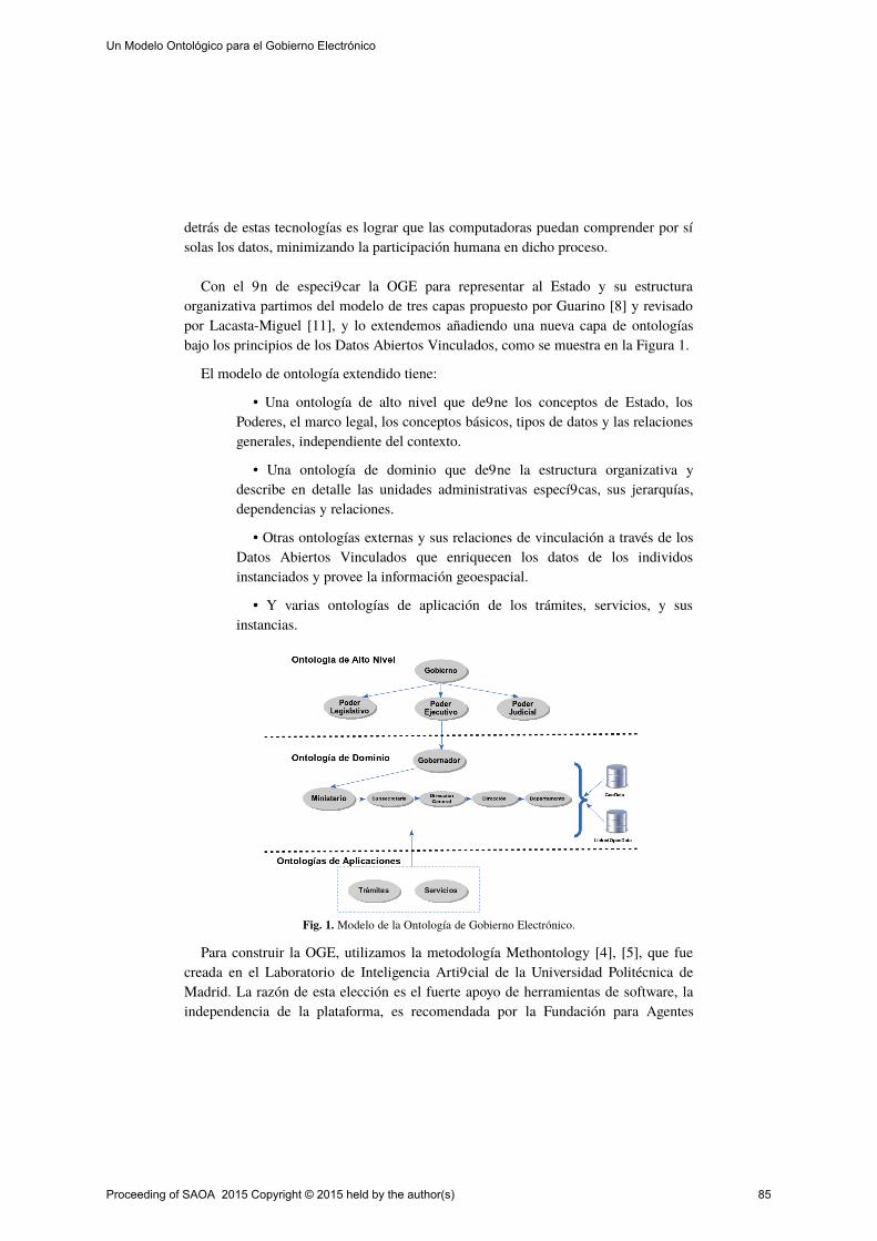
detrás de estas tecnologías es lograr que las computadoras puedan comprender por sísolas los datos, minimizando la participación humana en dicho proceso.
Con el fin de especificar la OGE para representar al Estado y su estructuraorganizativa partimos del modelo de tres capas propuesto por Guarino [8] y revisadopor Lacasta-Miguel [11], y lo extendemos añadiendo una nueva capa de ontologíasbajo los principios de los Datos Abiertos Vinculados, como se muestra en la Figura 1.
El modelo de ontología extendido tiene:
• Una ontología de alto nivel que define los conceptos de Estado, losPoderes, el marco legal, los conceptos básicos, tipos de datos y las relacionesgenerales, independiente del contexto.
• Una ontología de dominio que define la estructura organizativa ydescribe en detalle las unidades administrativas específicas, sus jerarquías,dependencias y relaciones.
• Otras ontologías externas y sus relaciones de vinculación a través de losDatos Abiertos Vinculados que enriquecen los datos de los individosinstanciados y provee la información geoespacial.
• Y varias ontologías de aplicación de los trámites, servicios, y susinstancias.
Fig. 1. Modelo de la Ontología de Gobierno Electrónico.
Para construir la OGE, utilizamos la metodología Methontology [4], [5], que fuecreada en el Laboratorio de Inteligencia Artificial de la Universidad Politécnica deMadrid. La razón de esta elección es el fuerte apoyo de herramientas de software, laindependencia de la plataforma, es recomendada por la Fundación para Agentes
Proceeding of SAOA 2015 Copyright © 2015 held by the author(s) 85
Un Modelo Ontológico para el Gobierno Electrónico
Físicos Inteligentes (FIPA) para el desarrollo de ontologías, ha sido probada en variosproyectos a gran escala y se ha aplicado con éxito en el desarrollo de ontologías parala gestión del conocimiento de gobierno abierto [14], [2].
Por lo tanto, siguiendo las pautas metodológicas de Methontology, para laespecificación, se definió el alcance y la granularidad. Para el proceso deconceptualización, se relevó la estructura organizacional y las normas legales que lasustentan. Estos datos actualmente se registran en formularios de papel yorganigramas. Los diferentes conceptos que se estudiaron fueron enumerados, acontinuación, se agruparon por similitud y utilidad. Para el mapeo de losorganigramas del árbol de la estructura administrativa utilizamos la aplicaciónCmapTools COE. Para la etapa de implementación, los organigramas representadosen los mapas conceptuales fueron exportados al Lenguaje de Ontologías Web (OWL)y luego editadas usando el editor OWL Protégé de la Universidad de Standford paraañadir las clases, atributos, relaciones y datos de geolocalización.
En el nivel superior, definimos las super clases relacionadas con conceptosgenerales, como Estado, el Gobierno, los Poderes, el marco legal y el territorio.Luego, para el nivel de dominio específico, definimos las clases de gobiernoelectrónico para la estructura administrativa y de los puestos, la gobernación y suestructura ministerial, la infraestructura (edificios), las oficinas de atnción al público ylos agentes. En esta etapa hemos modelado la organización administrativa de acuerdocon la recomendación de la W3C para ontologías de organización [18]. Esta ontologíadescribe a la gobernación, la vicegobernación, 10 ministerios, 37 subsecretarías, 68direcciones generales, 114 direcciones, y 326 departamentos.
Finalmente en el nivel de aplicación definimos las clases para los trámites yservicios para los ciudadanos. Para cada clase, buscamos sus instancias, lasincorporamos a la ontología específica y las mapeamos con otras si fuera necesario.
Esta relación entre el Estado, el gobierno y sus divisiones se puede representar enlógica descriptiva con la propiedad has, el subgrupo, la cuantificación existencial ySímbolos de la unión de la siguiente manera:
Estado hasPower.(Ejecutivo Legislativo Judicial)⊆ ∃ ∪ ∪Ejecutivo hasDivision. (Gobernador (Ministerio ... Ministerio)⊆ ∃ ∪ ∪ ∪Ministerio Subsecretarías Direcciones Generales Direcciones Departamentos⊆ ⊆ ⊆ ⊆
Además de la organización administrativa, se necesitan representar a los otroselementos del Estado. Para ello, desarrollamos las ontologías que describen el marcojurídico, el territorio (para lugares geolocalizados), la infraestructura (para oficinasadministrativas) y la estructura de los puestos administrativos (las personas).
Proceeding of SAOA 2015 Copyright © 2015 held by the author(s) 86
Un Modelo Ontológico para el Gobierno Electrónico

4.1. Mapeo de Ontologías
Un modelo de ontología taxonómica no puede representar satisfactoriamente lacomplejidad del Estado, entonces es necesario ampliar el dominio de la OGEvinculándola con otras fuentes de información externa y abierta. Para esto, sonreutilizadas otras ontologías por ejemplo OSMonto: una ontología de las etiquetas deOpenStreetMap, donde cada organización administrativa individual en la OGE estárepresentada en OpenStreetMap por un “nodo” o una “via”. Estos nodos tienen las“etiquetas” definidas en la ontología OSMonto que coinciden con algunos atributosde los individuos en la ontología OGE. También relacionamos la OGE con otrasfuentes de datos como FOAF, DBpedia, GeoNames y LinkedGeoData, como semuestra en la Figura 2.
En un primer paso, nos enfocamos sólo en las oficinas administrativas que estánabiertas al público y ofrecen un servicio del gobierno. Cada individuo está vinculadoa su nodo geolocalizado en OpenStreetMap, y GeoNames. Esto permite la integracióncon un amplio espectro de fuentes de datos abiertos locales y externas.
Fig. 2. Mapeo entre de la Ontología de Gobierno Electrónico y Datos Abiertos Vinculados.
Proceeding of SAOA 2015 Copyright © 2015 held by the author(s) 87
Un Modelo Ontológico para el Gobierno Electrónico
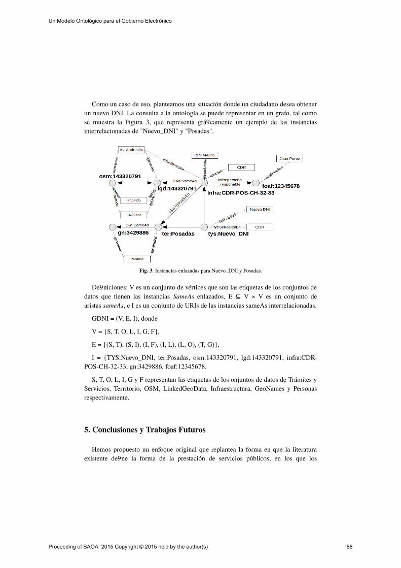
Como un caso de uso, planteamos una situación donde un ciudadano desea obtenerun nuevo DNI. La consulta a la ontología se puede representar en un grafo, tal comose muestra la Figura 3, que representa gráficamente un ejemplo de las instanciasinterrelacionadas de "Nuevo_DNI" y "Posadas".
Fig. 3. Instancias enlazadas para Nuevo_DNI y Posadas.
Definiciones: V es un conjunto de vértices que son las etiquetas de los conjuntos dedatos que tienen las instancias SameAs enlazados, E V × V es un conjunto de⊆aristas sameAs, e I es un conjunto de URIs de las instancias sameAs interrelacionadas.
GDNI = (V, E, I), donde
V = S, T, O, L, I, G, F,
E = (S, T), (S, I), (I, F), (I, L), (L, O), (T, G),
I = TYS:Nuevo_DNI, ter:Posadas, osm:143320791, lgd:143320791, infra:CDR-POS-CH-32-33, gn:3429886, foaf:12345678.
S, T, O, L, I, G y F representan las etiquetas de los onjuntos de datos de Trámites yServicios, Territorio, OSM, LinkedGeoData, Infraestructura, GeoNames y Personasrespectivamente.
5. Conclusiones y Trabajos Futuros
Hemos propuesto un enfoque original que replantea la forma en que la literaturaexistente define la forma de la prestación de servicios públicos, en los que los
Proceeding of SAOA 2015 Copyright © 2015 held by the author(s) 88
Un Modelo Ontológico para el Gobierno Electrónico

ciudadanos tienen que saber dónde y cómo hacer sus trámites. Con este modelo, losservicios públicos son los que encuentran a los ciudadanos y lo entregan dondequieraque ellos estén, en sus propios dispositivos móviles.
También llegamos a la conclusión de que el actual modelo es adecuado como unmarco de apoyo para la integración y la interoperabilidad de los servicios públicosprestados por las oficinas de administración distribuidas geográficamente.
En conclusión, el modelo propuesto es un paso exitoso en la evolución delgobierno electrónico a un nivel semántico, contribuye a la integración einteroperabilidad de los procesos que van más allá de las fronteras geográficas y losestados administrativos, y alcanzar la meta más importante del gobierno electrónico:prestar servicios más eficientes para los ciudadanos, ahorrando su tiempo y dinero.
Referencias
1. Berners-Lee T. (2006). Linked Data. http://www.w3.org/DesignIssues/LinkedDa-ta.html
2. Brusa, G., Caliusco, M. L., & Chiotti, O. (2013). Gestión del Conocimiento en el Gobierno Abierto: Ontologías de Dominio. In JAIIO (Ed.), 42 Jorandas Argentinas de Informática. 7mo Simposio Argentino De Informatica En El Estado (pp. 8–22). Córdoba. Retrieved from http://42jaiio.sadio.org.ar/proceedings/simposios/Trabajos/SIE/12.pdf
3. EGW3C (2008) eGovernment at W3C. Use Case: Open Government: Linked Open Data. http://www.w3.org/egov/wiki/Use_Case_8_-_Linked_Open_Government
4. Fernández-López, M., Gómez-Pérez, A., Juristo, N. (1997): Methontology: from on-tological art towards ontological engineering. In Proc. Symposium on Ontological Engineering of AAAI. (33-40)
5. Gómez-Pérez A., Fernández-López M., Corcho O., (2004). Ontological Engineering,Editorial: Springer Verlag GmH & Co. ISBN: 1-85233-551-3
6. GPSC The Geoportal of the Swiss Confederation. (2011) http://www.geo.admin.ch/internet/geoportal/en/home.htm
7. Gruber, T. (1993). A translation approach to portable ontology specifications. Knowledge Acquisition 199–220.
8. Guarino N. (1998). Formal Ontologies and Information Systems. Proceedings of FOIS’98, 3-15. Trento, Italy
9. Hodgson R., Allemang D., (2006), Semantic Technology For e-Government, Seman-tic Web and Beyond Volume 3, 2006, pp 283-303, Springer US, ISBN 978-0-387-30239-3.
10. Hreño, J., Bednár, P., Furdík, K., & Sabol, T. (2011). Integration of government ser-vices using semantic technologies. Journal of Theoretical and …, 6(1), 143–154. doi:10.4067/S0718-18762011000100010
Proceeding of SAOA 2015 Copyright © 2015 held by the author(s) 89
Un Modelo Ontológico para el Gobierno Electrónico
11. Lacasta-Miguel, J., López-Pellicer, F.J., Floristán-Jusué, J., Nogueras-Iso, J., Zarazaga-Soria, F.J.(2006): Unidades administrativas, una perspectiva ontológica. Avances en las Infraestructuras de Datos Espaciales. Treballs dínformática i tecnologia. Castelló de la Plana: Universidad Jaime I de Castellón. (85-94). ISBN 84-8021-590-9.
12. Orthofer G. and Wimmer M., (2006), An Ontology for eGovernment: Linking the Scientific Model with Concrete Projects, Semantic Web Meets eGovernment, Papers from the 2006 AAAI Spring Symposium: Semantic Web Meets eGovernment, pp. 96-98.
13. Ouchetto, H., Ouchetto, O., & Roudiès, O. (2012). Ontology-oriented e-gov services retrieval. IJCSI International Journal of Computer Science, 9, 99–107.
14. Sabucedo L., Rifon L., (2006) Semantic Service Oriented Architectures for eGovern-ment Platforms. American Association for Artificial Intelligence. AAAI. In Proc. 2006 AAAI Spring Symposium.
15. Stadler C., Lehmann J., Höffner K., Auer S., (2011) LinkedGeoData: A Core for a Web of Spatial Open Data. Semantic Web -Interoperability, Usability, Applicability an IOS Press Journal, 1570-0844/0-1900
16. Tambouris E., Gorilas S., Kavadias G., Apostolou D., Abecker A., Stojanovic L., Mentzas G., (2004), Ontology-enabled E-government Service Configuration-the On-toGov Approach. Springer Berlin Heidelberg. Knowledge Management in Electronic Government. Lecture Notes in Computer Science Volume 3035, 2004, pp 122-127.
17. Vassilakis, C., & Lepouras, G. (2006). Ontology for e-Government Public Services. Encyclopedia of E-Commerce, E-Government, and Mobile Commerce (pp. 865-870).
18. (W3C) The World Wide Web Consortium (2013). Recommendation for "The Organi-zation Ontology". Available a. http://www.w3.org/TR/vocab-org/
Proceeding of SAOA 2015 Copyright © 2015 held by the author(s) 90
Un Modelo Ontológico para el Gobierno Electrónico

DCOntoRep: hacia la interoperabilidad semántica de Repositorios Institucionales de Acceso abierto
Sandobal Verón, Valeria C.; Ale, Mariel; Gutiérrez, María de los Milagros
GIESIN, UTN FRR Resistencia, H3500CHJ, Argentina – [email protected] CIDISI, UTN FRSF, Santa Fe, S3004EWB, Argentina
Resumen. Debido a la heterogeneidad de los sistemas que sirven de repositorio para el almacenamiento de objetos digitales, ha surgido con interés el desarrollo de ontologías que permita interpretar de manera correcta el significado de los conceptos involucrados. Los objetos digitales depositados en repositorios deben ser etiquetados, catalogados y clasificados y para ello se utilizan los llamados metadatos, que proveen información sobre los objetos digitales. Es así que surgen estándares de metadatos tales como Dublin Core (DC) para la descripción de recursos web, Learning Object Model (LOM) para la descripción de recursos educativos específicamente; entre otros. Si se considera que se busca la comunicación entre los repositorios existentes, se hace necesaria la correcta interpretación semántica de los conceptos involucrados en los metadatos. La adopción de uno de estos estándares para la implementación de un repositorio depende de los objetivos que la institución ejecutora persiga. El presente trabajo propone una ontología para el estándar DC con las directrices del Sistema Nacional de Repositorios Digitales (SNRD). Teniendo en cuenta que el estándar DC es el más utilizado por los repositorios actualmente vigentes y las directrices SNRD lo utilizan a fin de poder adherir un futuro repositorio institucional a los cosechados por el Ministerio de Ciencia, Tecnología e Innovación Productiva
Keywords: objetos digitales, estándares de metadatos, Repositorios institucionales de acceso abierto, Dublin Core, recomendaciones SNRD
1 Introducción
En los últimos años se ha visto un incremento considerable en el uso e implementación de Repositorios institucionales de acceso abierto a partir de la promulgación de la ley 268991 que exige a los organismos e instituciones públicas que forman parte del Sistema Nacional de Ciencia y Tecnología publicar en acceso abierto, su producción científica – tecnológica. En este contexto, surge un extenso conjunto de problemáticas que deben ser resueltas, entre las cuales se puede
1 Sitio Web Ministerio de Ciencia, Tecnología e Innovación Productiva. Ley
26899.http://repositorios.mincyt.gob.ar/recursos.php
Proceeding of SAOA 2015 Copyright © 2015 held by the author(s) 91

mencionar las tecnológicas, relacionadas con la implementación, funcionamiento y uso. Este trabajo hace su aporte en el área de la interoperabilidad, específicamente en la interoperabilidad semántica de la información almacenada. El valor de un repositorio institucional de acceso abierto es su potencial para interoperar con otros repositorios formando una red de repositorios la cual configura una infraestructura de e-investigación [1]. Para lograr este objetivo, surge la necesidad de estandarizar la manera de describir los objetos almacenados, de forma tal que permitan búsquedas más concretas de los recursos disponibles, como así también la reutilización de los mismos. Es así que surgen estándares de metadatos tales como el Dublin Core (DC – Metadata Element Set)[2] que permite la descripción de cualquier tipo de recurso disponible en la web y LOM Learning Object Model [3] el cual se utiliza para la descripción de recursos educativos específicamente. Sin embargo el simple uso de estos estándares no garantiza la correcta localización y descripción de los recursos, por lo tanto el Sistema Nacional de Repositorios Digitales (SNRD) ha establecido una normativa donde se especifica la forma en que dichos metadatos deben ser completados [4]. El objetivo de este trabajo es aportar una herramienta semántica, específicamente una ontología denominada DCOntoRep, que dé soporte a la descripción de objetos de aprendizajes (LO por su sigla en inglés Learning Object) de una manera estandarizada, considerando no sólo el estándar DC sino también incorporando las directivas de SNRD a través de la definición de axiomas, reglas de derivación e instancias en la ontología propuesta. La misma será implementada en el Repositorio Institucional (RI) que se obtenga como resultado del proyecto de investigación que actualmente se está llevado a cabo en centro de investigación CIDISI – Facultad Regional Santa Fe: “Desarrollo e Implementación de un repositorio institucional de acceso abierto para objetos digitales educativos”. Dado que dicho repositorio se plantea para albergar objetos digitales educativos, es decir aquellos generados desde la parte académica de la universidad, como así también desde el área de investigación y tecnología, es que en este trabajo se considera apropiado utilizar el concepto de LO, teniendo en cuenta que el mismo puede definirse como “una entidad, digital o no digital, que puede ser utilizada, reutilizada y referenciada durante el aprendizaje apoyado con tecnología” [5], o como lo define García Aretio [6]: “archivos o unidades digitales de información dispuestos con la intención de ser utilizados en diferentes propuestas y contextos pedagógicos.” Se define el objetivo de DCOntoRep como: “representar la semántica explícita en las etiquetas utilizadas por el estándar DC y las directrices SNRD que permita mejorar la búsqueda, reutilización y depósito de LO, en los repositorios institucionales que utilizan este estándar”.
2 Desarrollo de DCOntoRep
Una ontología es una especificación formal y explícita de una conceptualización compartida [7]. Por lo tanto debe tener una especificación, una definición y debe ser explícita teniendo en cuenta el contexto en el que se la está utilizando; además de que
Proceeding of SAOA 2015 Copyright © 2015 held by the author(s) 92
DCOntoRep: hacia la interoperabilidad semántica de Repositorios Institucionales de Acceso abierto

la misma es compartida, por lo cual debe ser entendida por al menos dos actores involucrados en la especificación. La ontología que a continuación se presenta, tiene como base de información un archivo semiestructurado XML. Según [8] los métodos propuestos para el aprendizaje de una ontología se pueden clasificar en: aprendizaje desde corpus de texto, aprendizaje desde instancias, aprendizajes desde esquemas y aprendizajes desde mapeos semánticos. Siguiendo la propuesta realizada por [9] a partir de archivo XML generado con las etiquetas del estándar DC se aplican las heurísticas definidas tales como: las clases OWL surgen de tipos complejos (<xsd:complexType>); la figura 1(a) muestra esta heurística con el tipo complejo LearningObject. Las clases OWL surgen de elementos a nivel de esquema de un tipo complejo; la figura 1(b) muestra esta heurística con el tipo complejo Title que es parte del esquema DCMetadata. Los Object Property (relaciones) en OWL, surgen a partir de las relaciones entre elementos y subelementos del archivo XML, como se muestra en la figura 2 con la relación hasSubject. Los Data Property (atributos) de OWL surgen de tipos simples, tales como xs:date, xs:string, mostrado en la figura 3. En este mapeo resulta necesario, algunas otras conversiones tale como: facetas para restringir valores de elementos simples como Enumeration, que pueden ser definido en OWL2 como valores de rango para los data property y los valores de MinOccurs y MaxOccurs se especifican como valores que deben ser cumplidos en la estructura del Equivalent to
Etiquetas XML Clases OWL
(a)
(b)
Fig. 1. Mapeos entre elementos de XML a clases OWL
Proceeding of SAOA 2015 Copyright © 2015 held by the author(s) 93
DCOntoRep: hacia la interoperabilidad semántica de Repositorios Institucionales de Acceso abierto
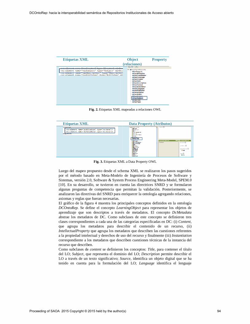
Etiquetas XML Object Property (relaciones)
Fig. 2. Etiquetas XML mapeadas a relaciones OWL
Etiquetas XML Data Property (Atributos)
Fig. 3. Etiquetas XML a Data Property OWL
Luego del mapeo propuesto desde el schema XML se realizaron los pasos sugeridos por el método basado en Meta-Modelo de Ingeniería de Procesos de Software y Sistemas, versión 2.0, Software & System Process Engineering Meta-Model, SPEM.0 [10]. En su desarrollo, se tuvieron en cuenta las directrices SNRD y se formularon algunas preguntas de competencia que permitan la validación. Posteriormente, se analizaron las directivas del SNRD para enriquecer la ontología agregando relaciones, axiomas y reglas que fueran necesarias. El gráfico de la figura 4 muestra los principales conceptos definidos en la ontología DCOntoRep. Se define el concepto LearningObject para representar los objetos de aprendizaje que son descriptos a través de metadatos. El concepto DcMetadata abstrae los metadatos de DC. Como subclases de este concepto se definieron tres clases correspondientes a cada una de las categorías especificadas en DC: (i) Content, que agrupa los metadatos para describir el contenido de un recurso, (ii) IntellectualProperty que agrupa los metadatos que describen las cuestiones referentes a la propiedad intelectual y derechos de uso del recurso y finalmente (iii) Instantiation correspondiente a los metadatos que describen cuestiones técnicas de la instancia del recurso que describen. Como subclases de content se definieron los conceptos: Title, para contener el título del LO; Subject, que representa el dominio del LO; Description permite describir el LO a través de un texto significativo; Source, identifica un objeto digital que se ha tenido en cuenta para la formulación del LO; Language identifica el lenguaje
Proceeding of SAOA 2015 Copyright © 2015 held by the author(s) 94
DCOntoRep: hacia la interoperabilidad semántica de Repositorios Institucionales de Acceso abierto
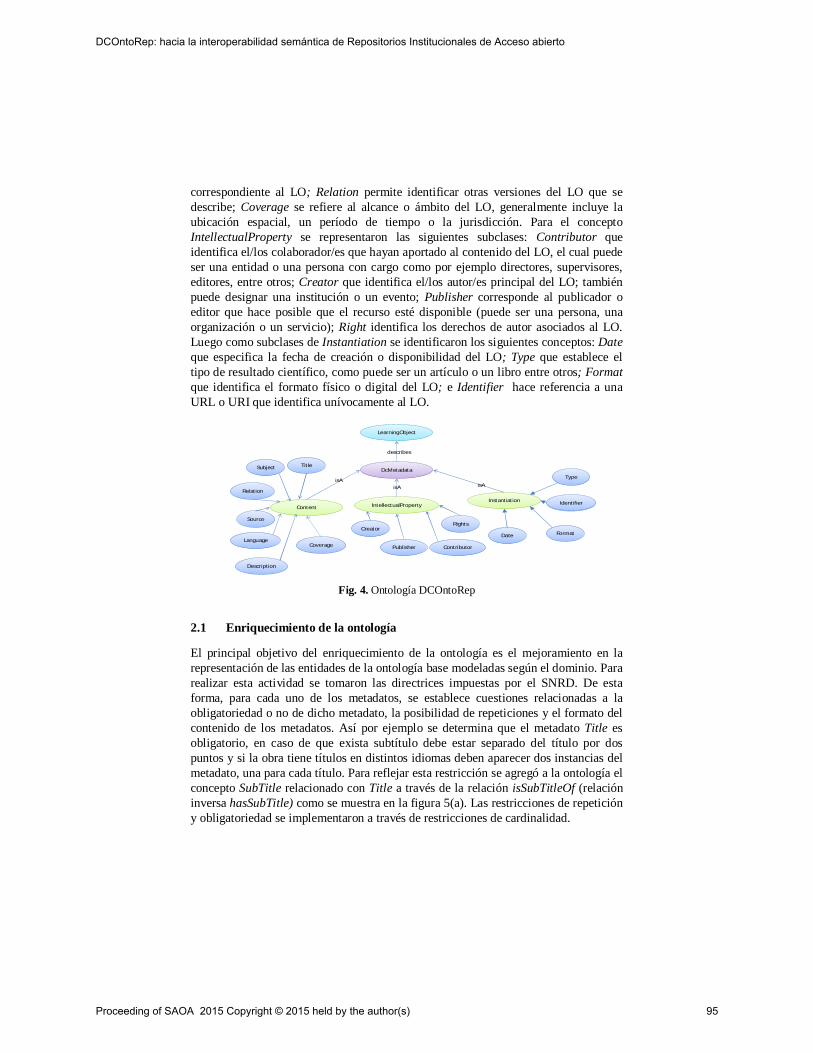
correspondiente al LO; Relation permite identificar otras versiones del LO que se describe; Coverage se refiere al alcance o ámbito del LO, generalmente incluye la ubicación espacial, un período de tiempo o la jurisdicción. Para el concepto IntellectualProperty se representaron las siguientes subclases: Contributor que identifica el/los colaborador/es que hayan aportado al contenido del LO, el cual puede ser una entidad o una persona con cargo como por ejemplo directores, supervisores, editores, entre otros; Creator que identifica el/los autor/es principal del LO; también puede designar una institución o un evento; Publisher corresponde al publicador o editor que hace posible que el recurso esté disponible (puede ser una persona, una organización o un servicio); Right identifica los derechos de autor asociados al LO. Luego como subclases de Instantiation se identificaron los siguientes conceptos: Date que especifica la fecha de creación o disponibilidad del LO; Type que establece el tipo de resultado científico, como puede ser un artículo o un libro entre otros; Format que identifica el formato físico o digital del LO; e Identifier hace referencia a una URL o URI que identifica unívocamente al LO.
Fig. 4. Ontología DCOntoRep
2.1 Enriquecimiento de la ontología
El principal objetivo del enriquecimiento de la ontología es el mejoramiento en la representación de las entidades de la ontología base modeladas según el dominio. Para realizar esta actividad se tomaron las directrices impuestas por el SNRD. De esta forma, para cada uno de los metadatos, se establece cuestiones relacionadas a la obligatoriedad o no de dicho metadato, la posibilidad de repeticiones y el formato del contenido de los metadatos. Así por ejemplo se determina que el metadato Title es obligatorio, en caso de que exista subtítulo debe estar separado del título por dos puntos y si la obra tiene títulos en distintos idiomas deben aparecer dos instancias del metadato, una para cada título. Para reflejar esta restricción se agregó a la ontología el concepto SubTitle relacionado con Title a través de la relación isSubTitleOf (relación inversa hasSubTitle) como se muestra en la figura 5(a). Las restricciones de repetición y obligatoriedad se implementaron a través de restricciones de cardinalidad.
LearningObjectLearningObject
DcMetadataDcMetadata
describes
ContentContent IntellectualPropertyIntellectualPropertyInstantiationInstantiation
isAisA isA
TitleTitleSubjectSubject
DescriptionDescription
SourceSource
LanguageLanguage
RelationRelation
CoverageCoverage
CreatorCreator
PublisherPublisher ContributorContributor
RightsRights
DateDate
TypeType
FormatFormat
IdentifierIdentifier
Proceeding of SAOA 2015 Copyright © 2015 held by the author(s) 95
DCOntoRep: hacia la interoperabilidad semántica de Repositorios Institucionales de Acceso abierto
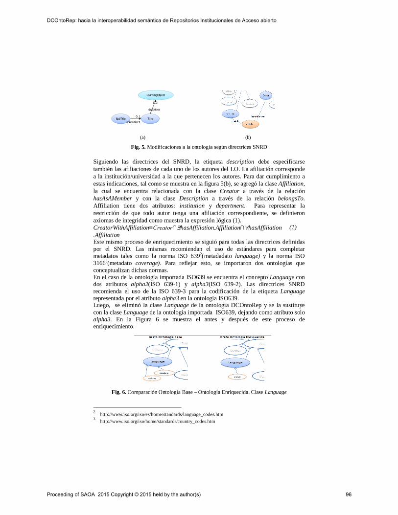
(a) (b)
Fig. 5. Modificaciones a la ontología según directrices SNRD
Siguiendo las directrices del SNRD, la etiqueta description debe especificarse también las afiliaciones de cada uno de los autores del LO. La afiliación corresponde a la institución/universidad a la que pertenecen los autores. Para dar cumplimiento a estas indicaciones, tal como se muestra en la figura 5(b), se agregó la clase Affiliation, la cual se encuentra relacionada con la clase Creator a través de la relación hasAsAMember y con la clase Description a través de la relación belongsTo. Affiliation tiene dos atributos: institution y department. Para representar la restricción de que todo autor tenga una afiliación correspondiente, se definieron axiomas de integridad como muestra la expresión lógica (1). CreatorWithAffiliation≡Creator∩∃hasAffiliation.Affiliation∩∀hasAffiliation.Affiliation
(1)
Este mismo proceso de enriquecimiento se siguió para todas las directrices definidas por el SNRD. Las mismas recomiendan el uso de estándares para completar metadatos tales como la norma ISO 6392(metadadato language) y la norma ISO 31663(metadato coverage). Para reflejar esto, se importaron dos ontologías que conceptualizan dichas normas. En el caso de la ontología importada ISO639 se encuentra el concepto Language con dos atributos alpha2(ISO 639-1) y alpha3(ISO 639-2). Las directrices SNRD recomienda el uso de la ISO 639-3 para la codificación de la etiqueta Language representada por el atributo alpha3 en la ontología ISO639. Luego, se eliminó la clase Language de la ontología DCOntoRep y se la sustituye con la clase Language de la ontología importada ISO639, dejando como atributo solo alpha3. En la Figura 6 se muestra el antes y después de este proceso de enriquecimiento.
Fig. 6. Comparación Ontología Base – Ontología Enriquecida. Clase Language
2 http://www.iso.org/iso/es/home/standards/language_codes.htm 3 http://www.iso.org/iso/home/standards/country_codes.htm
LearningObjectLearningObject
TitleTitle
describes
1..2
SubTitleSubTitleisSubtitleOf
0..1
Proceeding of SAOA 2015 Copyright © 2015 held by the author(s) 96
DCOntoRep: hacia la interoperabilidad semántica de Repositorios Institucionales de Acceso abierto
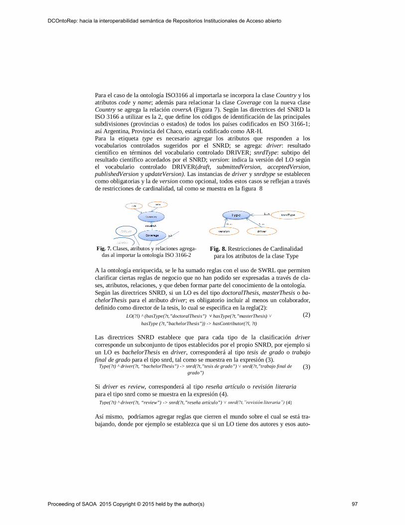
Para el caso de la ontología ISO3166 al importarla se incorpora la clase Country y los atributos code y name; además para relacionar la clase Coverage con la nueva clase Country se agrega la relación coversA (Figura 7). Según las directrices del SNRD la ISO 3166 a utilizar es la 2, que define los códigos de identificación de las principales subdivisiones (provincias o estados) de todos los países codificados en ISO 3166-1; así Argentina, Provincia del Chaco, estaría codificado como AR-H. Para la etiqueta type es necesario agregar los atributos que responden a los vocabularios controlados sugeridos por el SNRD; se agrega: driver: resultado científico en términos del vocabulario controlado DRIVER; snrdType: subtipo del resultado científico acordados por el SNRD; version: indica la versión del LO según el vocabulario controlado DRIVER(draft, submittedVersion, acceptedVersion, publishedVersion y updateVersion). Las instancias de driver y snrdtype se establecen como obligatorias y la de version como opcional, todos estos casos se reflejan a través de restricciones de cardinalidad, tal como se muestra en la figura 8
Fig. 7. Clases, atributos y relaciones agrega-das al importar la ontología ISO 3166-2
Fig. 8. Restricciones de Cardinalidad para los atributos de la clase Type
A la ontología enriquecida, se le ha sumado reglas con el uso de SWRL que permiten clarificar ciertas reglas de negocio que no han podido ser expresadas a través de cla-ses, atributos, relaciones, y que deben formar parte del conocimiento de la ontología. Según las directrices SNRD, si un LO es del tipo doctoralThesis, masterThesis o ba-chelorThesis para el atributo driver; es obligatorio incluir al menos un colaborador, definido como director de la tesis, lo cual se especifica en la regla(2):
LO(?l) ^ (hasType(?t,”doctoralThesis”) ˅ hasType(?t,”masterThesis) ˅ hasType (?t,”bachelorThesis”)) -> hasContributor(?l, ?t)
(2)
Las directrices SNRD establece que para cada tipo de la clasificación driver corresponde un subconjunto de tipos establecidos por el propio SNRD, por ejemplo si un LO es bachelorThesis en driver, corresponderá al tipo tesis de grado o trabajo final de grado para el tipo snrd, tal como se muestra en la expresión (3).
Type(?t) ^ driver(?t, “bachelorThesis”) -> snrd(?t,”tesis de grado”) ˅ snrd(?t,”trabajo final de grado”)
(3)
Si driver es review, corresponderá al tipo reseña artículo o revisión literaria para el tipo snrd como se muestra en la expresión (4).
Type(?t) ^ driver(?t, “review”) -> snrd(?t,”reseña artículo”) ˅ snrd(?t,”revisión literaria”) (4)
Así mismo, podríamos agregar reglas que cierren el mundo sobre el cual se está tra-bajando, donde por ejemplo se establezca que si un LO tiene dos autores y esos auto-
Proceeding of SAOA 2015 Copyright © 2015 held by the author(s) 97
DCOntoRep: hacia la interoperabilidad semántica de Repositorios Institucionales de Acceso abierto
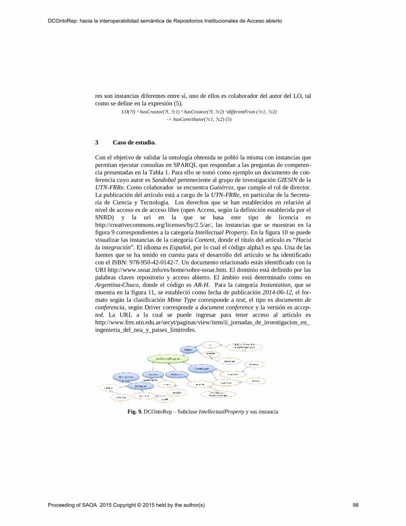
res son instancias diferentes entre sí, uno de ellos es colaborador del autor del LO, tal como se define en la expresión (5).
LO(?l) ^ hasCreator(?l, ?c1) ^ hasCreator(?l, ?c2) ^differentFrom (?c1, ?c2) -> hasContributor(?c1, ?c2) (5)
3 Caso de estudio.
Con el objetivo de validar la ontología obtenida se pobló la misma con instancias que permitan ejecutar consultas en SPARQL que respondan a las preguntas de competen-cia presentadas en la Tabla 1. Para ello se tomó como ejemplo un documento de con-ferencia cuyo autor es Sandobal perteneciente al grupo de investigación GIESIN de la UTN-FRRe. Como colaborador se encuentra Gutiérrez, que cumple el rol de director. La publicación del artículo está a cargo de la UTN-FRRe, en particular de la Secreta-ría de Ciencia y Tecnología. Los derechos que se han establecidos en relación al nivel de acceso es de acceso libre (open Access, según la definición establecida por el SNRD) y la uri en la que se basa este tipo de licencia es http://creativecommons.org/licenses/by/2.5/ar/, las instancias que se muestran en la figura 9 correspondientes a la categoría Intellectual Property. En la figura 10 se puede visualizar las instancias de la categoría Content, donde el título del artículo es “Hacia la integración”. El idioma es Español, por lo cual el código alpha3 es spa. Una de las fuentes que se ha tenido en cuenta para el desarrollo del artículo se ha identificado con el ISBN: 978-950-42-0142-7. Un documento relacionado estás identificado con la URI http://www.ssoar.info/es/home/sobre-ssoar.htm. El dominio está definido por las palabras claves repositorio y acceso abierto. El ámbito está determinado como en Argentina-Chaco, donde el código es AR-H. Para la categoría Instantation, que se muestra en la figura 11, se estableció como fecha de publicación 2014-06-12, el for-mato según la clasificación Mime Type corresponde a text, el tipo es documento de conferencia, según Driver corresponde a document conference y la versión es accep-ted. La URL a la cual se puede ingresar para tener acceso al artículo es http://www.frre.utn.edu.ar/secyt/paginas/view/item/ii_jornadas_de_investigacion_en_ingenieria_del_nea_y_paises_limitrofes.
Fig. 9. DCOntoRep – Subclase IntellectualProperty y sus instancia
Proceeding of SAOA 2015 Copyright © 2015 held by the author(s) 98
DCOntoRep: hacia la interoperabilidad semántica de Repositorios Institucionales de Acceso abierto
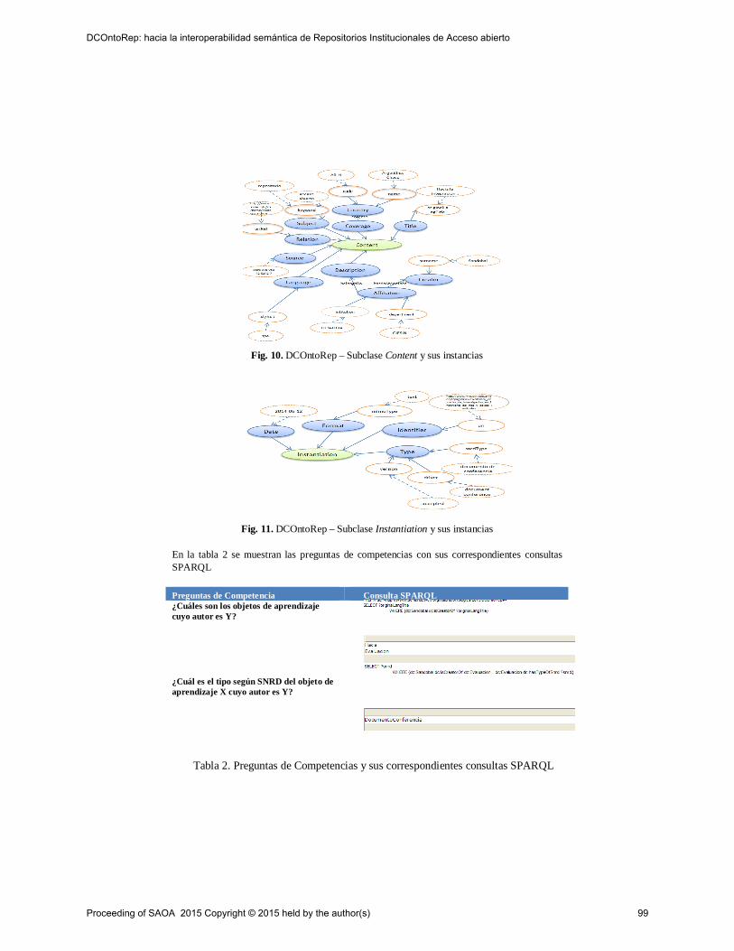
Fig. 10. DCOntoRep – Subclase Content y sus instancias
Fig. 11. DCOntoRep – Subclase Instantiation y sus instancias
En la tabla 2 se muestran las preguntas de competencias con sus correspondientes consultas SPARQL
Preguntas de Competencia Consulta SPARQL ¿Cuáles son los objetos de aprendizaje cuyo autor es Y?
¿Cuál es el tipo según SNRD del objeto de aprendizaje X cuyo autor es Y?
Tabla 2. Preguntas de Competencias y sus correspondientes consultas SPARQL
Proceeding of SAOA 2015 Copyright © 2015 held by the author(s) 99
DCOntoRep: hacia la interoperabilidad semántica de Repositorios Institucionales de Acceso abierto
4 Conclusiones
El presente artículo presenta una ontología basada en el estándar DC considerando las directrices SNRD para la utilización en la descripción de LO que se encuentran en repositorios institucionales. El trabajo consistió en entender el significado de cada una de las etiquetas propuestas por el estándar DC y su adecuación en las directrices SNRD para proponer una ontología que responda a la misma. Al contar con la des-cripción específica de los metadatos, se recurrió a las preguntas de competencia para que sirvan de guía en la validación de la ontología obtenida. Así mismo, en el docu-mento de especificación de requerimientos se planteó que la ontología dé soporte a: (i) la búsqueda de objetos digitales descriptos a través de metadatos en DC, (ii) guiar al usuario en la correcta introducción de los valores de las etiquetas de los objetos digitales. A partir de las consideraciones antes mencionadas y las evaluaciones realizadas de las preguntas de competencias ejecutadas en SPARQL es posible afirmar que la ontología responde a los requerimientos especificados. La ontología obtenida se considera una aproximación hacia la construcción de ontologías para el uso de metadatos, que ayude a definir un mapeo ontológico entre estándares de metadatos. Este trabajo forma parte de un proyecto que tiene como objetivo la implementación de un repositorio institu-cional en UTN – FRSF que se encuentra en la fase de prototipo. Como trabajo futuro, se utilizará ésta ontología en el prototipo para su validación y verificación.
Referencias
[1]COAR: Confederation of Open Access Repositories. The Current State of Open Access Repository Interoperability. Working Group 2: Repository Interoperability. Octubre 2012. [2]National information standards organization, “The Dublin core metadata element set”, ISSN 1041-5635, 2013 [3] IEEE Standard for Learning Object Metadata. (2002). Learning Technology Standards Comittee of the IEEE Computer Society. 1484.12.1-2002 [4] SNRD (2013). Directrices SNRD: Directrices para proveedores de contenido del Sistema Nacional de Repositorios Digitales Ministerio de Ciencia, Tecnología e Innovación Productiva. [5] IEEE. Learning Technology Standards Committee, 2002, p 45. [6] García Aretio. “Objetos de Aprendizaje”. Bol. Elect. de Noticias de Educación a Distancia – Bened. Disponible en: http://e-spacio.uned.es/fez/eserv.php?pid=bibliuned:329&dsID=editorialfebrero2005.pdf [7] Studer R., Benjamins VR, Fensel D. Knowledge Engineering: Principles and Methods. IEEE Transac-tion and Data and Knowledge Engineering 25(1-2) :161-197. 1998 [8] Giraldo, Gloria; Marín Juan C.; Urrego Giraldo, Germán. Extracción de elementos de una ontología de dominio a partir de documentos esquema. Revistas Avances en Sistemas e Informática. Vol 6 Nº2, Sep-tiembre 2009. Medellín. ISSN1657-7663 [9] Yahia, Nora; Moktar, Sahar; Wahab Ahmed, Abdel. Automatic Generation of OWL Ontology from XML Data Source.(2012). CoRR, abs/1026.0570 [10] Software & System Process Engineering Metamodel Specification (SPEM). Version 2.0 Object Managment Group, 2008. www.omg.org/spec/SPEM/2.0/
Proceeding of SAOA 2015 Copyright © 2015 held by the author(s) 100
DCOntoRep: hacia la interoperabilidad semántica de Repositorios Institucionales de Acceso abierto
Uso de Ontologías para mapear una Arquitectura deSoftware con su Implementación
H. C. Vázquez1,2, J. A. Díaz Pace1,2, and C. Marcos1,3
1 ISISTAN Research Institute. UNICEN University. Campus Universitario, Tandil(B7001BBO), Buenos Aires, Argentina. Tel.: +54 (249) 4439682.
2 Consejo Nacional de Investigaciones Científicas y Técnicas (CONICET).3 CIC, Committee for Scientific Research B1900AYB, La Plata, Argentina.
Resumen La arquitectura de software de un sistema es un activo importante parauna organización que desarrolla software. Para maximizar los beneficios que pro-vee una arquitectura, ésta debe estar en correspondencia con la implementacióndel sistema. En muchos proyectos existe cierta documentación de la arquitectura,pero sin embargo, la información de mapeos entre los elementos de dicha arqui-tectura y su implementación en código es escasa o inexistente. Este problema traeaparejadas dificultades de entendimiento de los elementos de código en relacióna la arquitectura originalmente diseñada, lo que repercute negativamente sobre elaseguramiento de la calidad y los esfuerzos de mantenimiento del sistema. Si bienla provisión manual de estos mapeos es factible, es una tarea compleja y proclivea errores, particularmente a medida que la implementación del sistema evolu-ciona en el tiempo. En este contexto, las técnicas de alineación de ontologías sepresentan como una alternativa para producir mapeos en forma automática. Poresta razón, el presente trabajo propone un enfoque automatizado y basado en on-tologías para la generación de mapeos entre la arquitectura de un sistema y suimplementación.
1. Introducción
La arquitectura de un sistema de software [3] se refiere a la organización de alto ni-vel del sistema, que comprende elementos de software, las propiedades externamentevisibles de esos elementos, y las relaciones entre ellos. Una arquitectura de softwa-re [3] proporciona un modelo que hace explícitas las principales decisiones de diseñorespecto a la satisfacción de atributos de calidad (por ej., performance, disponibilidad,modificabilidad, entre otros). A medida que un sistema evoluciona, comienzan a exis-tir discrepancias entre la arquitectura “según se documentó” y su implementación “encódigo” [10]. La acumulación de cambios (típicamente, en la implementación) tiendea “erosionar” la arquitectura inicial. Este problema impacta negativamente sobre losesfuerzos de mantenimiento y el aseguramiento de la calidad del sistema.
Una práctica que permite mantener la arquitectura alineada (y consistente) con suimplementación es la conformidad arquitectural [16]. Esta práctica se refiere a verificarperiódicamente las relaciones entre los elementos arquitectónicos y sus contrapartes enla implementación, previniendo posibles violaciones de las reglas de arquitectura y re-parando aquellas que puedan existir. En la actualidad, existen varias herramientas queayudan al arquitecto a desarrollar con la conformidad arquitectural (por ej., Archium[9], ArchJava [1]). Para esto, el prerrequisito es contar con mapeos entre los elementos
Proceeding of SAOA 2015 Copyright © 2015 held by the author(s) 101

de la arquitectura (por ej., componentes, responsabilidades, escenarios) y los elementosde la implementación (por ej., paquetes, clases, métodos). Es habitual encontrar descrip-ciones de la arquitectura prevista del sistema, pero generalmente los mapeos entre dichaarquitectura y el código son escasos o inexistentes. Esto no permite capitalizar en losbeneficios que provee la arquitectura. Si bien es factible que un arquitecto/desarrolladordefina en forma manual los mapeos de la arquitectura a una versión dada del sistema,esta tarea suele ser compleja y requiere un análisis detallado de la implementación. Es-te problema se acentúa a medida que la implementación del sistema evoluciona en eltiempo.
En este contexto, un enfoque alternativo para producir mapeos en forma automáti-ca son las técnicas de alineación de ontologías [6]. Una ontología es una formulaciónexplícita de un esquema conceptual, que permite la abstracción de entidades y sus re-laciones dentro de una estructura determinada [8]. Si se considera la arquitectura desoftware como un representación conceptual del sistema, tanto la semántica de la ar-quitectura como el código correspondiente pueden ser utilizados para crear ontologíasque representen sus conceptos y relaciones más importantes. En este trabajo se propo-ne la utilización de dos ontologías, una para representar la arquitectura y otra para suimplementación. Estas ontologías pueden ser luego alineadas de forma automática paraestablecer correspondencias entre sus entidades. Dichas correspondencias proveen losmapeos entre elementos de la arquitectura y su implementación.
El resto del trabajo se estructura de la siguiente manera. En la Sección 2 se presentanlos aspectos más importantes del enfoque propuesto para la generación de mapeos. LaSección 3 discute algunos resultados de la evaluación del enfoque con casos de estudio.En la Sección 4, se analizan algunos trabajos relacionados. Finalmente, la Sección 5presenta las conclusiones del trabajo y menciona trabajos futuros.
Figura 1: Un enfoque para establecer mapeos entre elementos de la arquitectura y su implemen-tación.
2. Enfoque propuesto
La ausencia de mapeos entre la arquitectura de un sistema y su implementación di-ficulta: el entendimiento del código en relación a su diseño arquitectónico original, elmantenimiento evolutivo del sistema y la práctica de chequeo de conformidad arquitec-
Proceeding of SAOA 2015 Copyright © 2015 held by the author(s) 102
Uso de Ontologías para mapear una Arquitectura de Software con su Implementación

tural. Por esta razón, en este trabajo se propone un enfoque para la generación automá-tica de mapeos que permita identificar correspondencias entre elementos de la arqui-tectura y su implementación (Figura 1). A partir de una descripción de la arquitecturay del código fuente, se definen dos ontologías, denominadas “ontología arquitectóni-ca” y “ontología de la implementación”, respectivamente. Luego, estas dos ontologíasson tomadas como entradas por el proceso de alineación, el cual tiene como objetivoencontrar las correspondencias entre ambas ontologías. Dicho proceso está compues-to por tres actividades: emparejamiento, cómputo de similitud y agrupamiento. En elemparejamiento, se generan todas las posibles parejas entre las entidades de las dosontologías. A partir de este emparejamiento, se realiza el cómputo de similitud de cadapareja de entidades basándose en sus características. Luego del cómputo de similitud serealiza el agrupamiento de las parejas de entidades de acuerdo al grado de similitud pre-sentado entre estas. Finalmente, se selecciona como resultado de la alineación el grupoque posee parejas de mayor similitud, las cuales se presentan como salida al usuario.
2.1. Definición de las ontologías
Una ontología es una especificación explícita de una conceptualización [8]. Algunasde las características más representativas de las ontologías que se adecuan a nuestroproblema son: la capacidad de adaptarse a distintos niveles de abstracción, y la posi-bilidad de realizar correspondencias de ontologías estableciendo relaciones entre loselementos de una o más ontologías, para establecer conexiones, especializaciones, ygeneralizaciones, entre otras. En este trabajo, las ontologías son definidas a través dellenguaje OWL (Ontology Web Lenguage [14]). OWL tiene como objetivo proporcionarun lenguaje que puede ser utilizado para describir las clases y las relaciones entre ellas,que son inherentes a documentos y aplicaciones Web. Sin embargo, es un lenguaje quetambién puede ser utilizado para representar otros tipos de descripciones como, porejemplo, la arquitectura de software y su implementación.
A continuación, se presentan las definiciones de la ontología arquitectónica y la on-tología de la implementación. Notar que la generación de ambas ontologías se realizaen forma automática.
Ontología arquitectónica Existen diversas formas de representar la arquitectura de unsistema y la relación entre sus componentes, este trabajo se basa en una vista parcial dela arquitectura denominada blueprint [11]. El blueprint es una vista de los componentesde alto nivel de un sistema y de sus interfaces hacia otros componentes. Un componen-te en esta vista arquitectónica representa una porción de código que tiene asignadasresponsabilidades (o concerns) del sistema. Estos componentes son vistos como “cajasnegras” y su interacción con el resto del sistema se realiza solo mediante sus interfa-ces. Las interfaces pueden ser provistas o requeridas, determinando así una forma dedependencia entre los componentes.
La representación blueprint se traduce a una ontología utilizando el lenguaje OWL(Figura 2). Los componentes se representan como clases OWL:Class, la dependenciaentre estos dada por las interfaces se traduce como propiedades OWL:ObjectProperty, ylos concerns simplemente se traducen como strings utilizando OWL:DatatypeProperty.Por ejemplo, en la figura 2, los componentes 1 y 2 son traducidos a dos clases OWLhomónimas, la “interface1to2” a una relación ObjectProperty, y los concerns a dosstrings.
Proceeding of SAOA 2015 Copyright © 2015 held by the author(s) 103
Uso de Ontologías para mapear una Arquitectura de Software con su Implementación

Ontología de la implementación La implementación de un sistema se lleva a cabomediante la producción de código. Para poder realizar los mapeos, este trabajo se basaen código escrito en el lenguaje Java. El código Java se traduce a una ontología OWL(Figura 2). En esta traducción, las clases Java se representan como OWL:Class, lasdependencias entre clases vía invocaciones a métodos se representan como propiedadesde objetos OWL:ObjectProperty. Adicionalmente, también pueden informarse concernsde la misma forma que en la ontología anterior utilizando OWL:DatatypeProperty. Estopermite que un concern pueda ser asociado a una clase cuando exista información detrazabilidad. Por ejemplo, en la figura 2, las clases Java 1 y 2 son traducidas a dos clasesOWL homónimas, la invocación a “method2” como una relación ObjectProperty, y enel caso de la clase 1, se informa el concern1 como string.
Figura 2: Definición de las ontologías a partir de la representación del sistema.
2.2. Alineación de las ontologías
A partir de las ontologías anteriores, es posible trazar una correspondencia entre losconceptos y relaciones de las mismas, lo que se conoce como alineación de ontologías[6]. La Figura3 muestra un pequeño ejemplo de arquitectura y su implementación. En laparte inferior se muestra la descripción (parcial) de un sistema dada por su blueprint ysu implementación (vista como clases e invocaciones a métodos); y en la parte superiorse muestra la representación ontológica de ambas.
Emparejamiento El emparejamiento de entidades de las ontologías se refiere al pro-ducto cartesiano entre los componentes (de la arquitectura) y las clases (de la implemen-tación). Para el ejemplo de la Figura 3, el emparejamiento de entidades se observa enel Cuadro 1, donde los componentes GUI_Elements, Business_Rules y Data_Manager,son cruzados con las clases GUI_Adapter, BusinessManager, BusinessRule, Business-DataManager y DataObject. Para problemas complejos (en términos de tamaño de lasontologías), por cuestiones de performance, podría pensarse en una forma de limitar losemparejamientos con información adicional, no obstante, ese problema no será aborda-do en este trabajo.
Proceeding of SAOA 2015 Copyright © 2015 held by the author(s) 104
Uso de Ontologías para mapear una Arquitectura de Software con su Implementación
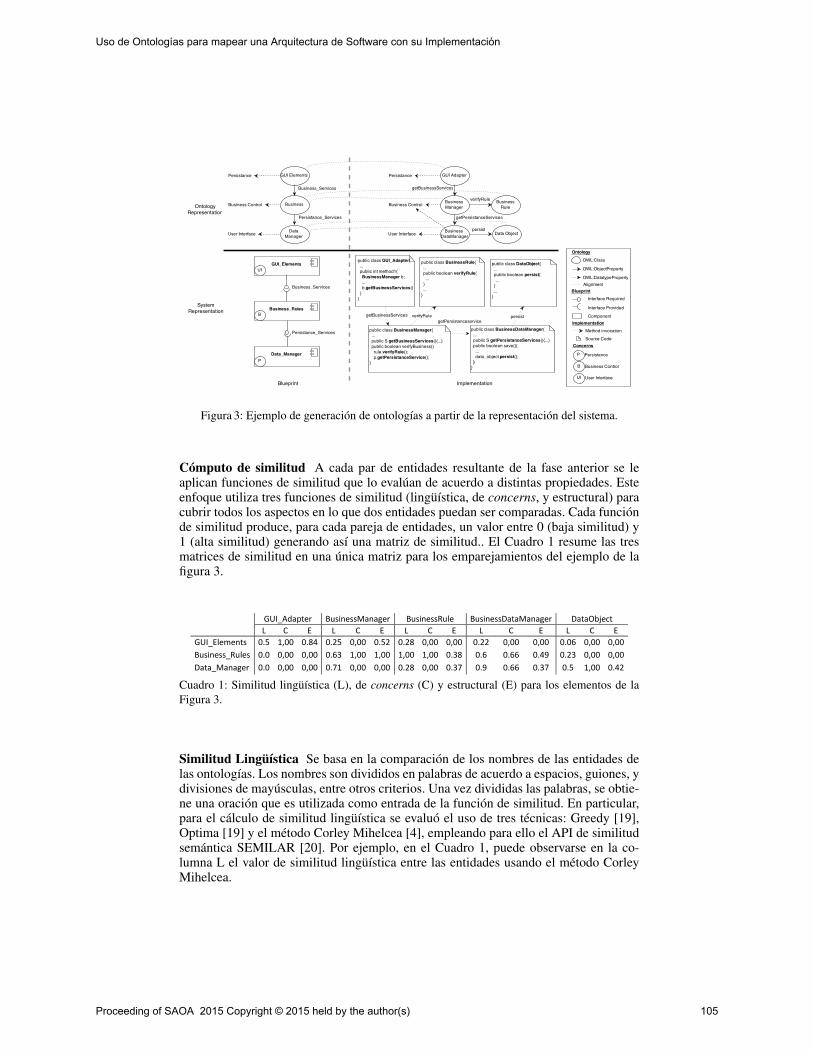
Figura 3: Ejemplo de generación de ontologías a partir de la representación del sistema.
Cómputo de similitud A cada par de entidades resultante de la fase anterior se leaplican funciones de similitud que lo evalúan de acuerdo a distintas propiedades. Esteenfoque utiliza tres funciones de similitud (lingüística, de concerns, y estructural) paracubrir todos los aspectos en lo que dos entidades puedan ser comparadas. Cada funciónde similitud produce, para cada pareja de entidades, un valor entre 0 (baja similitud) y1 (alta similitud) generando así una matriz de similitud.. El Cuadro 1 resume las tresmatrices de similitud en una única matriz para los emparejamientos del ejemplo de lafigura 3.
GUI_Adapter BusinessManager BusinessRule BusinessDataManager DataObject
L C E L C E L C E L C E L C E
GUI_Elements 0.5 1,00 0.84 0.25 0,00 0.52 0.28 0,00 0,00 0.22 0,00 0,00 0.06 0,00 0,00
Business_Rules 0.0 0,00 0,00 0.63 1,00 1,00 1,00 1,00 0.38 0.6 0.66 0.49 0.23 0,00 0,00
Data_Manager 0.0 0,00 0,00 0.71 0,00 0,00 0.28 0,00 0.37 0.9 0.66 0.37 0.5 1,00 0.42
Cuadro 1: Similitud lingüística (L), de concerns (C) y estructural (E) para los elementos de laFigura 3.
Similitud Lingüística Se basa en la comparación de los nombres de las entidades delas ontologías. Los nombres son divididos en palabras de acuerdo a espacios, guiones, ydivisiones de mayúsculas, entre otros criterios. Una vez divididas las palabras, se obtie-ne una oración que es utilizada como entrada de la función de similitud. En particular,para el cálculo de similitud lingüística se evaluó el uso de tres técnicas: Greedy [19],Optima [19] y el método Corley Mihelcea [4], empleando para ello el API de similitudsemántica SEMILAR [20]. Por ejemplo, en el Cuadro 1, puede observarse en la co-lumna L el valor de similitud lingüística entre las entidades usando el método CorleyMihelcea.
Proceeding of SAOA 2015 Copyright © 2015 held by the author(s) 105
Uso de Ontologías para mapear una Arquitectura de Software con su Implementación
Similitud de Concerns Un concern de software es cualquier aspecto que impacte so-bre la implementación de un sistema de software [22], generalmente impactando sobrevarios artefactos de software. Ejemplos típicos de concerns pueden ser aspectos de per-sistencia, seguridad, o performance. En nuestra representación, los concerns que afectanciertos elementos de la arquitectura, también pueden a afectar a los elementos de códi-go que materializan dichos componentes. La ecuación 1 muestra el cálculo de similitudde concerns entre dos entidades E1 y E2, calculada como la suma de los concerns deE1 y E2, sobre la suma de los concern de E1 que se encuentran en E2 más la suma delos concerns de E2 que se encuentran en E1. Esta información es representada en lacolumna C del Cuadro 1.
Similitud(E1,E2) =∑concernsE1 +∑concernsE2
∑concernsE1enE2 +∑concernsE2enE1(1)
Similitud Estructural Este tipo de similitud proviene de considerar las ontologías co-mo grafos dirigidos para poder analizar su estructura y determinar la correspondenciaentre sus nodos. En base a esta característica, se utiliza el algoritmo de matching de gra-fos Similarity Flooding (SFA) [15]. El SFA toma dos grafos como entrada y producecomo salida un mapeo entre los nodos de ambos grafos. Cabe destacar que el SFA uti-liza como entrada un mapeo inicial (o semilla), a fin de reducir su espacio de búsqueda.En este enfoque, para evitar la intervención del usuario, este mapeo inicial es resueltoutilizando las funciones de similitud lingüística y de concerns. Es decir, primeramentese buscan los mapeos para los cuales las funciones de similitud anteriores hayan pro-ducido un alto valor de similitud (muy cercano a 1), y se utilizan estos como semilladel SFA. Este proceso es descripto por el pseudocódigo 1. En la Cuadro 1, se puedeobservar en la columna E, el valor de similitud estructural usando el algoritmo SFA.
Algoritmo 1 Pseudocódigo del proceso de similitud estructural.1. G1 = Graph(Ontology1);2. G2 = Graph(Ontology2);3. initialMap = maxSimilarityMappings(G1, G2);4. similarityMatrix = SFA(G1, G2, initialMap);
Agrupamiento A partir de las matrices, se obtienen instancias de los pares de entida-des y sus valores de similitud. Finalmente, estas instancias son agrupadas mediante lautilización de una técnica de clustering [18] con el fin de reunir los pares de entidadesde acuerdo a la similitud de sus características. Particularmente, se utilizó la técnicade clustering K-Means [2]. K-Means tiene como objetivo la partición de un conjuntode n observaciones en k grupos, en el que cada observación pertenece al grupo máscercano a la media. Para este trabajo, el resultado de la alineación es el clúster con lamedia más cercana a 1, que es presentado en última instancia al usuario, como mapeosentre componentes y clases. En la Figura 3, la línea punteada entre las entidades ex-pone la alineación final, por ejemplo entre el componente Data_Manager y las clasesBusinessDataManager y DataObject
Proceeding of SAOA 2015 Copyright © 2015 held by the author(s) 106
Uso de Ontologías para mapear una Arquitectura de Software con su Implementación

3. Evaluación
En el área de alineación de ontologías, se utilizan generalmente los criterios de pre-cision y recall evaluar la performance del sistema de alineamiento [5]. Estas medidasson definidas por las ecuaciones siguientes:
Precision =(givenAlignment ∩ correctAlignment)
givenAlignment(2)
Recall =(givenAlignment ∩ correctAlignment)
correctAlignment(3)
Se denomina precision a la fracción de instancias recuperadas que son relevantes,mientras que recall es la fracción de instancias relevantes que han sido recuperadas.Además de estas dos medidas, se utilizó F-Measure como una medida armónica deprecision y recall. Esta medida está definida por la siguiente ecuación:
F−Measure =2∗Precision∗Recall
Precision+Recall(4)
F-measure es utilizada para evaluar qué tan lejos está la solución de la utilidad teóri-ca, y también para observar qué tan balanceadas están las medidas de precision y recall.
Descripción HWS MMLíneas de código (LOC) 8697 3015
Componentes 7 25Interfaces 14 70
Clases 135 51Métodos 1090 251
Cuadro 2: Descripción de los proyectos HWS y MM
Se utilizaron dos casos de estudio para validar el enfoque propuesto: i) el sistemaMobile Media (MM) [24] que es una SPL (Software Product Line) para aplicacionesmóviles, y ii) el sistema Health Watcher (HWS) [13] que es un sistema para recogery gestionar quejas y notificaciones relacionadas con la salud pública. Los mapeos dereferencia para MM y HWS fueron provistos por expertos en forma manual, a fin derealizar comparaciones contra los mapeos obtenidos automáticamente mediante nuestroenfoque. En la Cuadro 2 se provee una descripción breve de ambos proyectos, tanto anivel de arquitectura como de su implementación.
Se experimentó con el enfoque en los dos casos de estudio, y se realizaron pruebasvariando el valor K (cantidad de clusters) y la técnica de similitud lingüística, obtenien-do los resultados mostrados en la Cuadro 3. Estos resultados evidencian alrededor deK=20 un valor de f-measure superior al conseguido con otros K, lo que significa unmayor balance entre precision y recall. La técnica de similitud lingüística con la queel proceso de alineación arrojó resultados más precisos fue Greedy, con cerca del 95%para K=20, mientras que el recall se mantuvo cerca del 50%. Como era de esperar,para valores más altos de K=20 la medida precision aumenta, pero recall disminuyecomo puede observarse en la Figura 4. Esto se debe a que el aumento en el valor de Kdisminuye la cantidad promedio de instancias por cada clúster, lo que genera un trade-
Proceeding of SAOA 2015 Copyright © 2015 held by the author(s) 107
Uso de Ontologías para mapear una Arquitectura de Software con su Implementación

MM HWS
CorleyMihalcea Greedy Optimum CorleyMihalcea Greedy Optimum
K P R F P R F P R F P R F P R F P R F
2 0,07 0,68 0,13 0,08 0,68 0,15 0,09 0,68 0,16 0,22 0,98 0,37 0,22 0,98 0,37 0,22 0,98 0,37
4 0,22 0,37 0,27 0,25 0,48 0,33 0,34 0,59 0,43 0,85 0,58 0,69 0,77 0,55 0,64 0,85 0,53 0,66
6 0,23 0,21 0,22 0,51 0,41 0,45 0,53 0,39 0,45 0,85 0,58 0,69 0,89 0,40 0,55 0,85 0,53 0,66
8 0,38 0,35 0,36 0,62 0,39 0,48 0,60 0,39 0,47 0,85 0,58 0,69 0,96 0,39 0,56 0,89 0,41 0,56
10 0,79 0,31 0,44 0,62 0,39 0,48 0,66 0,38 0,48 0,89 0,39 0,54 0,96 0,40 0,56 0,89 0,40 0,55
12 0,79 0,31 0,44 0,71 0,35 0,47 0,69 0,34 0,45 0,94 0,40 0,56 0,96 0,40 0,56 0,96 0,40 0,56
14 0,41 0,34 0,37 0,69 0,35 0,47 0,74 0,32 0,45 0,94 0,39 0,55 0,96 0,40 0,56 0,96 0,40 0,56
16 0,88 0,30 0,44 0,71 0,35 0,47 0,74 0,32 0,45 0,94 0,39 0,55 0,96 0,40 0,56 0,96 0,40 0,56
18 0,88 0,30 0,44 0,73 0,34 0,46 0,73 0,34 0,46 0,94 0,40 0,56 0,96 0,40 0,56 0,96 0,40 0,56
20 0,88 0,30 0,44 0,95 0,30 0,45 0,88 0,31 0,46 0,94 0,40 0,56 0,96 0,40 0,56 0,96 0,40 0,56
22 0,87 0,28 0,43 0,88 0,31 0,46 0,88 0,31 0,46 0,94 0,40 0,56 0,96 0,40 0,56 0,96 0,40 0,56
24 0,91 0,28 0,43 0,95 0,28 0,43 0,88 0,30 0,44 0,94 0,40 0,56 0,96 0,40 0,56 1,00 0,38 0,55
26 0,86 0,27 0,41 0,95 0,28 0,43 0,88 0,31 0,46 1,00 0,17 0,29 0,96 0,39 0,56 1,00 0,38 0,55
28 0,92 0,17 0,29 0,95 0,28 0,43 0,88 0,31 0,46 1,00 0,17 0,29 0,96 0,39 0,56 1,00 0,38 0,55
30 0,92 0,17 0,29 0,95 0,28 0,43 0,88 0,30 0,44 1,00 0,17 0,29 0,96 0,39 0,56 1,00 0,38 0,55
32 0,90 0,27 0,41 0,95 0,28 0,43 0,88 0,30 0,44 1,00 0,17 0,29 0,96 0,39 0,56 1,00 0,38 0,55
34 0,92 0,17 0,29 0,93 0,18 0,31 0,88 0,31 0,46 1,00 0,17 0,29 1,00 0,38 0,55 1,00 0,38 0,55
36 0,92 0,17 0,29 0,93 0,18 0,31 0,88 0,31 0,46 1,00 0,17 0,29 1,00 0,38 0,55 1,00 0,38 0,55
38 0,92 0,17 0,29 0,95 0,25 0,40 0,95 0,27 0,42 1,00 0,17 0,29 1,00 0,38 0,55 1,00 0,38 0,55
40 0,92 0,17 0,29 0,95 0,27 0,42 0,95 0,25 0,40 1,00 0,17 0,29 1,00 0,38 0,55 1,00 0,38 0,55
Cuadro 3: Resultados de precision (P), recall (R) y f-measure (F) de la herramienta de alineación.
off entre precision y recall. Entre estas dos medidas se prioriza precision, dado que esmás importante que los mapeos que se recuperen sean correctos, a que se recuperenmuchos mapeos a costa de introducir incorrectos. Mapeos erróneos pueden dar lugar arazonamientos incorrectos sobre los análisis que puedan hacerse entre la arquitecturay su implementación. En la Figura 4 puede verse que los valores de precision, recall yf-measure tienden a estabilizarse más rápido en el proyecto MM que el HWS. Esto sedebe a que la alineación depende exclusivamente de la correspondencia semántica entrelas ontologías, y esta puede ser más evidente en algunos proyectos y más difusa otros.
0,00
0,10
0,20
0,30
0,40
0,50
0,60
0,70
0,80
0,90
1,00
0 5 10 15 20 25 30 35 40
P
R
F
MM
0,00
0,10
0,20
0,30
0,40
0,50
0,60
0,70
0,80
0,90
1,00
0 5 10 15 20 25 30 35 40
P
R
F
HWS
Figura 4: Gráfico de de precision (P), recall (R) y f-measure (F) para distintos valores de K (ejex) utilizando Greedy.
4. Trabajos relacionados
Obtener un nivel de comprensión adecuado de la arquitectura de un sistema de soft-ware es importante por muchas razones [10]. En los últimos años, varias investigacioneshan explorado el uso de técnicas de Inteligencia Artificial para recuperar la arquitectura
Proceeding of SAOA 2015 Copyright © 2015 held by the author(s) 108
Uso de Ontologías para mapear una Arquitectura de Software con su Implementación

de un sistema a partir de su código fuente. En [17], se analizaron técnicas de Machi-ne Learning para condensar diagramas de clases en pos de obtener una representaciónde más alto nivel del diseño del sistema. Otros enfoques como [12] intentan recuperarla arquitectura del código fuente utilizando clustering. Un enfoque similar al anteriorfue utilizado en [7], donde el interés está primero en la recuperación de concerns delsistema implementado, y luego junto a información estructural, se intenta identificarautomáticamente componentes y conectores. Sin embargo, estos enfoques apuntan arecuperar la arquitectura desde la implementación en casos en los que no existe in-formación acerca de la arquitectura original del sistema. Este trabajo se centra en larecuperación de mapeos entre una arquitectura dada y la implementación del sistema,considerando que dicha arquitectura se conoce de antemano (ya sea porque existe algode documentación, o porque se ha consultado a un experto). Por otro lado, Jing Sunget al. [21] plantean una descripción ontológica de una arquitectura representada porcomponentes y conectores, y exponen algunas de las ventajas de las ontologías comorepresentación alternativa a los lenguajes de descripción de arquitecturas (ADLs). Apartir de eso, proponen un enfoque de diseño y verificación de modelos de arquitec-turas de software usando tecnología de web semántica. Si bien en nuestro enfoque esposible aprovechar técnicas de razonamiento ontológico, el aporte del presente trabajoconsiste en considerar la implementación del sistema como una ontología que se adecuea la ontología de la arquitectura, para luego obtener mapeos mediante la alineación dedichas ontologías.
5. Conclusiones
En este trabajo se presentó un enfoque para la generación automática de mapeos entreelementos de una descripción arquitectónica y elementos de la implementación, apro-vechando técnicas existentes de alineación de ontologías. Una constribución novedosadel enfoque es la combinación de tres medidas de similitud (lingüística, de concernsy estructural). El enfoque fue evaluado en dos casos de estudio, obteniendo buenosresultados en cuanto a precisión aunque con un recall moderado. Por otra parte, se en-contraron puntos a mejorar en el proceso de alineación. Uno de estos refiere a la funciónde similitud estructural, cuando existen diferencias de tamaño entre los grafos corres-pondientes al blueprint y a la implementación Java, ya que el algoritmo SFA no estápreparado para alinear grafos de tamaños muy dispares. Por lo tanto es necesario, comoun paso previo a la alineación, llevar ambas representaciones a un nivel de abstrac-ción similar, o bien, experimentar con otros algoritmos. Otra posible mejora consiste enaportar más información estructural al proceso de alineamiento mediante la inclusiónde una función de similitud basada en métricas de SNA (Social Network Analisys) [23].
Referencias
1. Aldrich, J., Chambers, C., Notkin, D.: Archjava: connecting software architecture to imple-mentation. In: Software Engineering, 2002. ICSE 2002. Proceedings of the 24rd InternationalConference on. pp. 187–197. IEEE (2002)
2. Arthur, D., Vassilvitskii, S.: k-means++: The advantages of careful seeding. In: Proceedingsof the eighteenth annual ACM-SIAM symposium on Discrete algorithms. pp. 1027–1035.Society for Industrial and Applied Mathematics (2007)
3. Bass, L., Clements, P., Kazman, R.: Software Architecture in Practice. Addison-Wesley Pro-fessional, 3rd edn. (2012)
Proceeding of SAOA 2015 Copyright © 2015 held by the author(s) 109
Uso de Ontologías para mapear una Arquitectura de Software con su Implementación
4. Corley, C., Mihalcea, R.: Measuring the semantic similarity of texts. In: Proceedings of theACL workshop on empirical modeling of semantic equivalence and entailment. pp. 13–18.Association for Computational Linguistics (2005)
5. Do, H.H., Rahm, E.: Matching large schemas: Approaches and evaluation. Information Sys-tems 32(6), 857–885 (2007)
6. Euzenat, J., Shvaiko, P., et al.: Ontology matching, vol. 18. Springer (2007)7. Garcia, J., Popescu, D., Mattmann, C., Medvidovic, N., Cai, Y.: Enhancing architectural
recovery using concerns. In: Proceedings of the 2011 26th IEEE/ACM International Confe-rence on Automated Software Engineering. pp. 552–555. IEEE Computer Society (2011)
8. Gruber, T.R.: A translation approach to portable ontology specifications. Knowledge acqui-sition 5(2), 199–220 (1993)
9. Jansen, A., Bosch, J.: Software architecture as a set of architectural design decisions. In:Software Architecture, 2005. WICSA 2005. 5th Working IEEE/IFIP Conference on. pp. 109–120. IEEE (2005)
10. Kazman, R., Woods, S.G., Jeromy Carriere, S.: Requirements for integrating software ar-chitecture and reengineering models: Corum ii. In: Reverse Engineering, 1998. Proceedings.Fifth Working Conference on. pp. 154–163. IEEE (1998)
11. Kruchten, P.B.: The 4+ 1 view model of architecture. Software, IEEE 12(6), 42–50 (1995)12. Maqbool, O., Babri, H.A.: Hierarchical clustering for software architecture recovery. Soft-
ware Engineering, IEEE Transactions on 33(11), 759–780 (2007)13. Massoni, T., Soares, S., Borba, P.: Requirements health-watcher version 2.0. Early Aspects,
ICSE 7 (2007)14. McGuinness, D.L., Van Harmelen, F., et al.: Owl web ontology language overview. W3C
recommendation 10(10), 2004 (2004)15. Melnik, S., Garcia-Molina, H., Rahm, E.: Similarity flooding: A versatile graph matching
algorithm and its application to schema matching. In: Data Engineering, 2002. Proceedings.18th International Conference on. pp. 117–128. IEEE (2002)
16. Moriconi, M., Qian, X., Riemenschneider, R.A.: Correct architecture refinement. SoftwareEngineering, IEEE Transactions on 21(4), 356–372 (1995)
17. Osman, M.H., Chaudron, M.R., Van Der Putten, P.: An analysis of machine learning algo-rithms for condensing reverse engineered class diagrams. In: Software Maintenance (ICSM),2013 29th IEEE International Conference on. pp. 140–149. IEEE (2013)
18. Rohlf, F.J.: NTSYS-pc: numerical taxonomy and multivariate analysis system. Applied Bios-tatistics (1992)
19. Rus, V., Lintean, M.: A comparison of greedy and optimal assessment of natural languagestudent input using word-to-word similarity metrics. In: Proceedings of the Seventh Works-hop on Building Educational Applications Using NLP. pp. 157–162. Association for Compu-tational Linguistics (2012)
20. Rus, V., Lintean, M.C., Banjade, R., Niraula, N.B., Stefanescu, D.: Semilar: The seman-tic similarity toolkit. In: ACL (Conference System Demonstrations). pp. 163–168. Citeseer(2013)
21. Sun, J., Wang, H.H., Hu, T.: Design software architecture models using ontology. In: SEKE.pp. 191–196 (2011)
22. Sutton Jr, S.M., Rouvellou, I.: Modeling of software concerns in cosmos. In: Proceedingsof the 1st international conference on Aspect-oriented software development. pp. 127–133.ACM (2002)
23. Wasserman, S.: Social network analysis: Methods and applications, vol. 8. Cambridge uni-versity press (1994)
24. Young, T.J.: Using aspectj to build a software product line for mobile devices. Ph.D. thesis,The University of British Columbia (2005)
Proceeding of SAOA 2015 Copyright © 2015 held by the author(s) 110
Uso de Ontologías para mapear una Arquitectura de Software con su Implementación
An Ontological Approach to Analyze the Data Required
by a System Quality Scheme
María Julia Blas, Silvio Gonnet
INGAR, Instituto de Desarrollo y Diseño UTN-CONICET, Santa Fe, Argentina mariajuliablas,[email protected]
Abstract. According to IEEE, software quality is the degree to which software
possesses a desired combination of attributes. Quality attributes have been of
interest to the software community since 1970 and in the past few years this
interest has increase. However, still is not clear how product quality should
apply in the development process. The need to know what quality
characteristics influence a specific entity and which is the information required
to cover its measurement is the objective of this work. This paper presents an
ontology to document a quality scheme with a specification based on ISO/IEC
25010. This contribution includes rules and queries that help to determine the
data required to carry out the measurement process.
Keywords: Ontology, quality scheme, software metrics, software product.
1 Introduction
The delimitation of what defines an adequate level of quality in a software system is a
highly context dependent question [1]. This problem changes with the product and
perspective of the stakeholders and, therefore, software product quality can easily
become an area full of problems and conflicts as long each stakeholder group has its
own perspective on what is important.
Everyone involved in the software engineering process is responsible for quality
[2]. Achieving quality attributes must be considered throughout design,
implementation, and deployment [3]. However, maintain the traceability of this
attributes in the development process is very difficult. Frequently, the attributes get
lost between different stages because there is no mechanism that supports the quality
decisions made in the previous phases. Or worse, the development team does not
know which attributes are related and how they impact in the overall quality of the
software product (SP). In this context, software community needs a mechanism that
not only provides the basic information related to quality but also leads to the correct
definition of a quality scheme (QS). A QS can be defined as a set of triplets where
each element is composed by one software attribute (that is, a part of a software entity
that requires some specific quality property), one software metric (that should be used
to measure the quality of the attribute) and one quality subcharacteristic (that should
be evaluated over the attribute). The application of a QS over a SP can be done by
Proceeding of SAOA 2015 Copyright © 2015 held by the author(s) 111
executing the measurement process over the specified artifact. However, before this
application is necessary to collect all the required information. Given that this
information may not be available is useful to analyze how a subset of data covers the
required metrics. To this purpose, this paper presents an ontological approach that
allows developers to document a QS and helps to analyze its coverage (taking into
account the availability of the information). This proposal defines three basic
elements: i) a quality scheme ontology (QSO) that establishes a way to define an
adequate QS; ii) a set of SWRL (Semantic Web Rule Language) rules [4] and
SPARQL (SPARQL Protocol and RDF Query Language) queries [5] that allows
developers to know the degree in which the available information covers the scheme;
and iii) an interactive activity which indicates how to use the previous elements. The
QSO proposed is based on three semantic models: software product quality semantic
model, metric semantic model and software semantic model. Although a lot of
authors have proposed ontologies for quality models and software metrics [6-8].
These ontologies are very detailed representation of a specific domain and their
combination is a complex task. Furthermore, the existing quality model ontologies are
outdated because the current normative [9] is relatively new. Therefore, none of these
ontologies is valid in the actual context.
The remainder of this paper is organized as follows. Section 2 describes the QSO
that should be used to define a QS for a specific SP. Section 3 explains the set of rules
and queries developed in order to derivate the coverage degree. Section 4 presents the
activity defined to apply the ontological approach. Finally, Section 5 is devoted to the
conclusions of the work.
2 Quality Scheme Ontology
The QSO developed is a domain ontology, since is applicable to a domain with a
specific view point [10]. This ontology is based on the combination of three semantic
models that represent specifics domains:
1. A software product quality semantic model that represents a product quality model.
2. A metric semantic model that represents concepts related to software metrics.
3. A software semantic model that represents the content of a software product.
A quality model is an essential component of a QS since is a model with the objective
to describe, assess and/or predict quality [11]. Software quality models are a well-
accepted means to support quality management of software systems. Furthermore, the
use of metrics to develop strategies for improving the quality of the end product is a
good practice [2]. A software metric is a measure of some property of a piece of
software code or its specifications [12]. Software quality metrics are useful to register
the current quality state of an end-product or process. To define a correct QS is
necessary to specify which artifacts of the software product have to be evaluated.
The proposed QSO unifies the three individual domains in a single model. An
attribute of a SP needs to be described by a quality subcharacteristic and has to be
measured by a metric. In this sense, the three elements define one specification of the
Proceeding of SAOA 2015 Copyright © 2015 held by the author(s) 112
An Ontological Approach to Analyze the Data Required by a System Quality Scheme
set of triples included at QS. Therefore, for each quality subcharacteristic, the
capability of a SP is determined by a set of internal attributes that can be measured.
Figure 1 shows the QSO. The gray nodes represent the concepts while the arrows
refer to the relationships. The arrow head indicates the direction of the relationship
and its label indicates the name. The empty arrows model “is-a” relationship, disjoint
and complete. The relationships highlighted in yellow represent links between the
different models. The boxes model the data properties of the concepts.
The upper part of Figure 1 shows the Software Product Quality Semantic Model.
Many quality models have been proposed to support stakeholders in dealing with
software quality. By novelty and completeness, the SP quality model presented in
ISO/IEC 25010 [9] is the most rigorous and complete of all. For these reasons, this
model has been taken as basis for this work.
The product quality model identifies the main characteristics of a SP in different
levels of hierarchy. It is composed of eight characteristics which are further
subdivided into subcharacteristics. A characteristic represents an external quality view
while a subcharacteristic refers to properties that can be evaluated when the software
is used as a part of a system. Each subcharacteristic is decomposed into a set of
attributes. An attribute is an entity which can be verified or measured in the SP. A
detail description of these concepts and relationships can be checked in [9].
In order to build this ontology, each characteristic and subcharacteristic identified
in the quality model was transformed in a concept. The relationships between these
concepts were modeled defining links between them. This definition took the form is-
decomposed-in. For example, the characteristic Functional Suitability is related with
the subcharacteristic Functional Appropriateness by the relationship called is-
decomposed-in-functional-appropriateness. To group these concepts in different
categories, the concepts Characteristic and Subcharacteristic were included. This
classification was made linking the concepts by an is-a relationship. This relationship
allows to modeling the taxonomy proposed in ISO/IEC 25010 [9]. The Quality Model
concept was also included in the semantic model. The relationship of this concept
with each characteristic was made by defining a new relationship that took the name
contains (e.g. contains-security). The includes relationship helps to determine which
characteristic are included in a Quality Model (since none of the characteristic is
mandatory). Once the main concepts were defined, a set of properties was included in
the model with the aim to refine the represented semantic. These properties include:
characteristic description, subcharacteristic description and source.
To complete the definition of the ontology, a set of SWRL rules related with the
contains relationship were specified. Equation 1 describes an example restriction that
shows that all security characteristic decomposed in an integrity subcharacteristic
must contain this subcharacteristic. Similar restrictions were added to the model to
guarantee that all characteristics contain the appropriate set of subcharacteristics.
Security(?x)∧isDecomposedInIntegrity(?x,?y)→contains(?x,?y) (1)
The bottom part of Figure 1 shows the Metric Semantic Model. The metric
ontology focuses in the traditional metric definition [2, 13, 14] and incorporates some
concepts of the current normative [15, 16]. According to ISO 9126, a metric is
Proceeding of SAOA 2015 Copyright © 2015 held by the author(s) 113
An Ontological Approach to Analyze the Data Required by a System Quality Scheme
basically defined by the specification of its name, purpose, application method,
measurement formula, interpretation, scale type, measure type, input to measurement
and target audience. The identification of the metric is given by its name. For this
reason, the metric name must be related with the information obtained when the
metric is applied. The purpose of the metric is expressed as the question to be
answered by the application of the metric. The metric application method provides an
outline of application while the measurement formula stipulates the mathematical
expression used for the calculation and explains the meanings of the used data
elements. The interpretation of the measured value supplies the range and preferred
values. The scale type defines the dimension of the metric. Scale types used are:
nominal scale, ordinal scale, interval scale, ratio scale and absolute scale. The
measure type involves the specification of the way in which the metric is obtained.
Types used are: size, time and count type. The input to the measurement process
refers to the source of data used in the measurement. Finally, the target audience
identifies the users of the measurement results.
Although all this concepts define a metric, only a set of them was used as part of
the metric ontology. The selection was made taking into account the final objective:
document the metrics related with different quality attributes that should be used to
evaluate a specific SP. In order to do this, the input to measurement and the target
audience are not represented in the model. To define a QS, the specific source of
information for a metric is not important since the measurement process is not
executed. The target audience is also a concept that shows a dependency with the use
of the metric and, therefore, is excluded of the model. The rest of the concepts were
taken to compose the semantic model. Furthermore, in order to improve and complete
the ontology some properties were refined. The first refinement was the incorporation
of the concepts Direct Metric and Indirect Metric. A Direct Metric is an atomic
metrics and an Indirect Metric is defined in term of another metrics. To define a
metric three complementary changes were made: the addition of the hierarchies Unit
and Scale and the incorporation of the Equation concept. The Unit hierarchy was
designed using as reference the proposal of Rijgersberg [17] while the Scale hierarchy
was modeled using the approach described by Olsina [8]. In order to include an
approach that allow to describing how a metric should be calculated, the Equation
concept was added to the model. This concept represents a mathematical formula
composed of mathematical terms, operators and variables.
The derivation of knowledge that refers to specific types of operations, units and
range delimitations is made by mean of SWRL rules. Equation 2 shows as example
that a unit must be assigned into a metric only if its scale is numerical, then the unit
will be the one specified in the scale.
Metric(?m) ∧ NumericalScale(?s) ∧ isDimensionedIn(?m,?s) ∧ isMeasuredIn(?s,?u) ∧ Unit(?u) → hasAsUnit(?m,?u) (2)
The middle part of Figure 1 shows the Software Semantic Model. Its purpose is to
model the domain of SPs. A SP is a set of computer programs, procedures, and
possibly associated documentation and data, designed for delivery to a specific user.
It always includes the development of one or more computer programs.
Proceeding of SAOA 2015 Copyright © 2015 held by the author(s) 114
An Ontological Approach to Analyze the Data Required by a System Quality Scheme

Fig. 1. Quality Scheme Ontology.
Proceeding of SAOA 2015 Copyright © 2015 held by the author(s) 115
An Ontological Approach to Analyze the Data Required by a System Quality Scheme
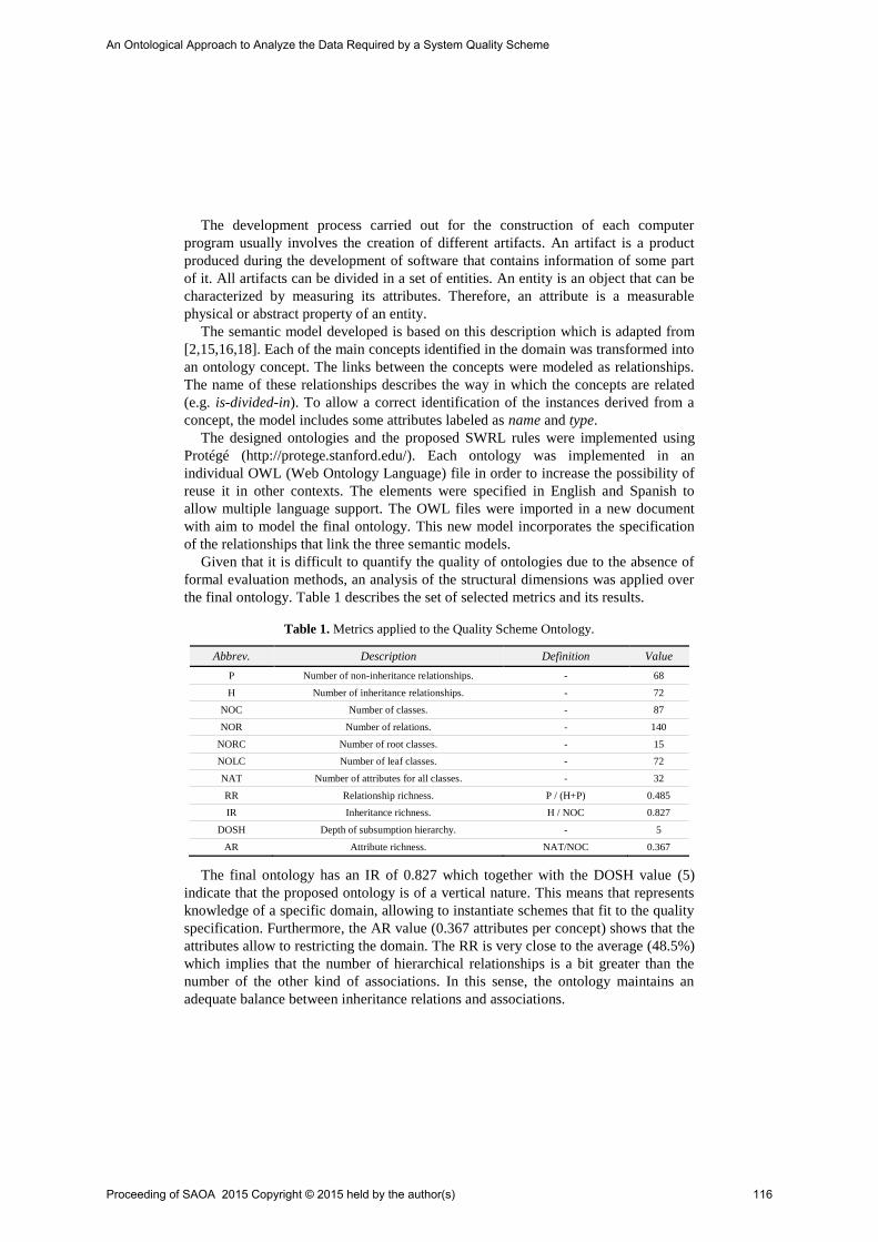
The development process carried out for the construction of each computer
program usually involves the creation of different artifacts. An artifact is a product
produced during the development of software that contains information of some part
of it. All artifacts can be divided in a set of entities. An entity is an object that can be
characterized by measuring its attributes. Therefore, an attribute is a measurable
physical or abstract property of an entity.
The semantic model developed is based on this description which is adapted from
[2,15,16,18]. Each of the main concepts identified in the domain was transformed into
an ontology concept. The links between the concepts were modeled as relationships.
The name of these relationships describes the way in which the concepts are related
(e.g. is-divided-in). To allow a correct identification of the instances derived from a
concept, the model includes some attributes labeled as name and type.
The designed ontologies and the proposed SWRL rules were implemented using
Protégé (http://protege.stanford.edu/). Each ontology was implemented in an
individual OWL (Web Ontology Language) file in order to increase the possibility of
reuse it in other contexts. The elements were specified in English and Spanish to
allow multiple language support. The OWL files were imported in a new document
with aim to model the final ontology. This new model incorporates the specification
of the relationships that link the three semantic models.
Given that it is difficult to quantify the quality of ontologies due to the absence of
formal evaluation methods, an analysis of the structural dimensions was applied over
the final ontology. Table 1 describes the set of selected metrics and its results.
Table 1. Metrics applied to the Quality Scheme Ontology.
Abbrev. Description Definition Value
P Number of non-inheritance relationships. - 68
H Number of inheritance relationships. - 72
NOC Number of classes. - 87
NOR Number of relations. - 140
NORC Number of root classes. - 15
NOLC Number of leaf classes. - 72
NAT Number of attributes for all classes. - 32
RR Relationship richness. P / (H+P) 0.485
IR Inheritance richness. H / NOC 0.827
DOSH Depth of subsumption hierarchy. - 5
AR Attribute richness. NAT/NOC 0.367
The final ontology has an IR of 0.827 which together with the DOSH value (5)
indicate that the proposed ontology is of a vertical nature. This means that represents
knowledge of a specific domain, allowing to instantiate schemes that fit to the quality
specification. Furthermore, the AR value (0.367 attributes per concept) shows that the
attributes allow to restricting the domain. The RR is very close to the average (48.5%)
which implies that the number of hierarchical relationships is a bit greater than the
number of the other kind of associations. In this sense, the ontology maintains an
adequate balance between inheritance relations and associations.
Proceeding of SAOA 2015 Copyright © 2015 held by the author(s) 116
An Ontological Approach to Analyze the Data Required by a System Quality Scheme

3 Analysis of the Required and Available Information
3.1 SWRL Rules Applied to the Derivation of Knowledge
In order to analyze a software QS, a set of SWRL rules was specified (Table 2). The
SWRL is a language that is used to express rules in the form of an implication
between an antecedent (body) and consequent (head) [4] and, therefore, allows to
derivate new knowledge from the instances of a model.
Since all direct metric refers to a measure or is used as component in an indirect
metric, the first rule specifies that a Direct Metric implies a need of information
(Required Data). However, if a required data is available it establishes an Available
Data (rule 2). In this sense, if a Direct Metric is also an Available Data (that is, the
information exists when the measurement process take place) then the metric is a
mathematical term than can be calculated (Calculable Term). This fact is expressed in
rule 3. But, the fact that a mathematical term can be calculated it may involve that
other mathematical terms can be calculated. To this purpose, rules 4 and 5 are
defined. In rule 4, if a Simple Term has as argument a mathematical term that is
calculable then it is a Calculable Term. The same happens with Complex Terms (rule
5). Then, if the mathematical term that resumes the Measurement Function associated
with an Indirect Metric is calculable, the metric is itself a Calculable Term (rule 6).
Finally, rule 7 specifies that if a Metric is a Calculable Term, then it is a Calculable
Metric. This rule allows to determinate if a metric (independently of its type) can be
calculated with the available data.
Table 2. SWRL rules.
Id. SWRL Rule
1 DirectMetric(?x) → RequiredData(?x)
2 RequiredData(?x) ˄ available(?x, true) → AvailableData(?x)
3 DirectMetric(?x) ˄ AvailableData(?x) → CalculableTerm(?x)
4 SimpleTerm(?s) ˄ CalculableTerm(?a) ˄ hasAsArgument(?s, ?a) → CalculableTerm(?s)
5 ComplexTerm(?c) ˄ CalculableTerm(?a1) ˄ CalculableTerm(?a2) ˄ hasAsFirstArgument(?c, ?a1) ˄
hasAsSecondArgument(?c, ?a2) → CalculableTerm(?c)
6 IndirectMetric(?m) ˄ MeasurementFunction(?f) ˄ CalculableTerm(?t) ˄ hasDefinition(?f, ?t) ˄
isCalculatedBy(?m, ?f) → CalculableTerm(?m)
7 Metric(?m) ˄ CalculableTerm(?m) → CalculableMetric(?m)
3.2 SPARQL Queries
A QS is defined for a specific SP. However, the quality is measured using the
attributes of the entities of the different artifacts of the software product. Therefore,
the coverage analysis of a QS over a set of available information must be done at
artifact level and the results must be detailed at entity level. To this purpose, the
coverage analysis is done at entity level. These results are combined in order to obtain
a value at artifact level.
Proceeding of SAOA 2015 Copyright © 2015 held by the author(s) 117
An Ontological Approach to Analyze the Data Required by a System Quality Scheme
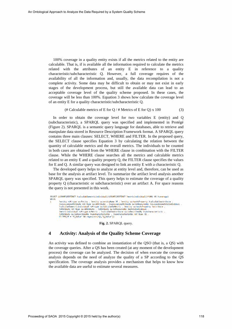
100% coverage in a quality entity exists if all the metrics related to the entity are
calculable. That is, if is available all the information required to calculate the metrics
related with the attributes of an entity E in reference to a quality
characteristic/subcharacteristic Q. However, a full coverage requires of the
availability of all the information and, usually, the data recompilation is not a
complete activity. Some data may be difficult to obtain or may not exist in early
stages of the development process, but still the available data can lead to an
acceptable coverage level of the quality scheme proposed. In these cases, the
coverage will be less than 100%. Equation 3 shows how calculate the coverage level
of an entity E for a quality characteristic/subcharacteristic Q.
(# Calculable metrics of E for Q / # Metrics of E for Q) x 100 (3)
In order to obtain the coverage level for two variables E (entity) and Q
(subcharacteristic), a SPARQL query was specified and implemented in Protégé
(Figure 2). SPARQL is a semantic query language for databases, able to retrieve and
manipulate data stored in Resource Description Framework format. A SPARQL query
contains three main clauses: SELECT, WHERE and FILTER. In the proposed query,
the SELECT clause specifies Equation 3 by calculating the relation between the
quantity of calculable metrics and the overall metrics. The individuals to be counted
in both cases are obtained from the WHERE clause in combination with the FILTER
clause. While the WHERE clause searches all the metrics and calculable metrics
related to an entity E and a quality property Q, the FILTER clause specifies the values
for E and Q. A similar query was designed to link an entity E with a characteristic Q.
The developed query helps to analyze at entity level and, therefore, can be used as
base for the analysis at artifact level. To summarize the artifact level analysis another
SPARQL query was specified. This query helps to estimate the coverage of a quality
property Q (characteristic or subcharacteristic) over an artifact A. For space reasons
the query is not presented in this work.
Fig. 2. SPARQL query.
4 Activity: Analysis of the Quality Scheme Coverage
An activity was defined to combine an instantiation of the QSO (that is, a QS) with
the coverage queries. After a QS has been created (at any moment of the development
process) the coverage can be analyzed. The decision of when execute the coverage
analysis depends on the need of analyze the quality of a SP according to the QS
specification. The coverage analysis provides a mechanism that helps to know how
the available data are useful to estimate several measures.
Proceeding of SAOA 2015 Copyright © 2015 held by the author(s) 118
An Ontological Approach to Analyze the Data Required by a System Quality Scheme
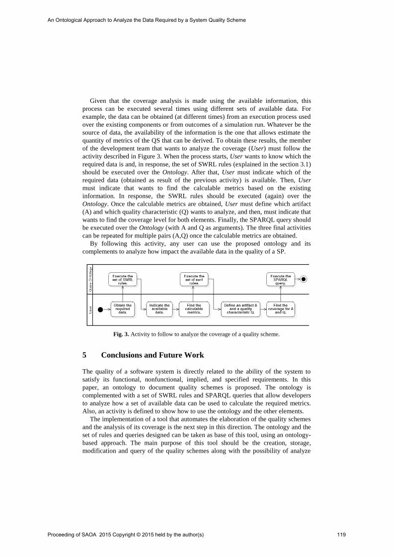
Given that the coverage analysis is made using the available information, this
process can be executed several times using different sets of available data. For
example, the data can be obtained (at different times) from an execution process used
over the existing components or from outcomes of a simulation run. Whatever be the
source of data, the availability of the information is the one that allows estimate the
quantity of metrics of the QS that can be derived. To obtain these results, the member
of the development team that wants to analyze the coverage (User) must follow the
activity described in Figure 3. When the process starts, User wants to know which the
required data is and, in response, the set of SWRL rules (explained in the section 3.1)
should be executed over the Ontology. After that, User must indicate which of the
required data (obtained as result of the previous activity) is available. Then, User
must indicate that wants to find the calculable metrics based on the existing
information. In response, the SWRL rules should be executed (again) over the
Ontology. Once the calculable metrics are obtained, User must define which artifact
(A) and which quality characteristic (Q) wants to analyze, and then, must indicate that
wants to find the coverage level for both elements. Finally, the SPARQL query should
be executed over the Ontology (with A and Q as arguments). The three final activities
can be repeated for multiple pairs (A,Q) once the calculable metrics are obtained.
By following this activity, any user can use the proposed ontology and its
complements to analyze how impact the available data in the quality of a SP.
Fig. 3. Activity to follow to analyze the coverage of a quality scheme.
5 Conclusions and Future Work
The quality of a software system is directly related to the ability of the system to
satisfy its functional, nonfunctional, implied, and specified requirements. In this
paper, an ontology to document quality schemes is proposed. The ontology is
complemented with a set of SWRL rules and SPARQL queries that allow developers
to analyze how a set of available data can be used to calculate the required metrics.
Also, an activity is defined to show how to use the ontology and the other elements.
The implementation of a tool that automates the elaboration of the quality schemes
and the analysis of its coverage is the next step in this direction. The ontology and the
set of rules and queries designed can be taken as base of this tool, using an ontology-
based approach. The main purpose of this tool should be the creation, storage,
modification and query of the quality schemes along with the possibility of analyze
Proceeding of SAOA 2015 Copyright © 2015 held by the author(s) 119
An Ontological Approach to Analyze the Data Required by a System Quality Scheme

the coverage for all quality characteristics. With this technological support, the
development team could easily understand the quality aspects related with a specific
software artifact and see how impact the available data in the measurement of quality.
The QSO can be adapted to other types of quality models since the software
product quality semantic model is an independent ontology. Although in this work the
view is centered in the internal quality attributes of a SP, the semantic model can be
replaced with a model that refers to quality in use. Also, it can be replaced with
quality models developed by other authors. The same changes are applicable to the
software ontology. Given that the semantic model is independent, the proposed
approach allows refining the model to represent a more detailed description of a SP.
The improvement of this model is the main objective of the future work to be made.
References
1. Kitchenham, B., Pfleeger, S.: Software Quality: The Elusive Target. IEEE Softw. 13(1996).
2. Pressman, R.: Software Engineering: A Practitioner´s Approach. McGraw-Hill (2010).
3. Bass, L., Clements, P., Kazman, R.: Software Architecture in Practice. Addison-Wesley
Professional (2003).
4. SWRL: A Semantic Web Rule Language, http://www.w3.org/Submission/SWRL/ (2004).
5. SPARQL 1.1 Query Language, http://www.w3.org/TR/sparql11-query/ (2013).
6. Pardo, C., Pino, F., García, F., Piattini, M., Baldassarre, M.: An ontology for the
harmonization of multiple standards and models, Computer Standards & Interfaces, 34, 1,
pp. 48–59 (2012).
7. Dominguez-Mayo, F., Escalona, M., Mejías, M. Ross, M., Stapes, G.: A quality
management based on the Quality Model life cycle, Computer Standards & Interfaces, 34,
4, pp. 396–412 (2012).
8. Olsina, L., Martín, M.: Ontology for Software Metrics and Indicators. J Web Eng. 2, 262–
281 (2003).
9. ISO/IEC 25010:2011 - System and software quality models, (2011). 10. Roussey, C., Pinet, F., Kang, M., Corcho, O.: An Introduction to Ontologies and Ontology
Engineering, Ontologies in Urban Development Projects, Advanced Information and
Knowledge Processing, 1, pp. 9-38 (2011).
11. Deissenboeck, F., Juergens, E., Lochmann, K.: Software quality models: Purposes, usage
scenarios and requirements, ICSE Workshop on Software Quality ’09. pp. 9–14 (2009).
12. El-Haik, B.S., Shaout, A.: Software Design for Six Sigma: A Roadmap for Excellence. John
Wiley & Sons (2010).
13. Fenton, N., Bieman, J.: Software Metrics: A Rigorous and Practical Approach, Third
Edition. CRC Press, Boca Raton (2014).
14. Kan, S.H.: Metrics and Models in Software Quality Engineering. Addison-Wesley
Professional (2003).
15. ISO/IEC TR 9126-2:2003 - Software Product quality - Part 2: External metrics, (2003).
16. ISO/IEC TR 9126-3:2003 - Software Product quality - Part 3: Internal metrics, (2003).
17. Rijgersberg, H., Wigham, M., Top, J.L.: How semantics can improve engineering
processes: A case of units of measure and quantities. Adv. Eng. Inform. 25, 276–287
(2011).
18. ISO/IEC 12207:2008 - Systems & software engineering - Software life cycle processes
(2008).
Proceeding of SAOA 2015 Copyright © 2015 held by the author(s) 120
An Ontological Approach to Analyze the Data Required by a System Quality Scheme

Extending the Conceptual Base for a Holistic Quality
Evaluation Approach
Belen Rivera, Pablo Becker and Luis Olsina
GIDIS_Web, Engineering School at Universidad Nacional de La Pampa, Argentina
[email protected], [beckerp, olsinal]@ing.unlpam.edu.ar
Abstract. For software organizations often performing measurement,
evaluation (ME), and even change/improvement (MEC) projects, a well-
established quality evaluation approach can be useful. In this direction, we
have developed a holistic quality evaluation approach whose architecture is
based on two pillars, namely: a quality multi-view modeling framework, and
ME/MEC integrated strategies. In this paper, we specify the conceptual base
for the former pillar. Specifically, we specify an ontology of quality views
documenting its main terms, properties and relationships. Quality views are
paramount for selecting evaluation strategies and strategy patterns to be
assigned as resources to ME/MEC projects. Also, we show how this ontology
is semantically linked with the previously built ME domain ontology.
Keywords: Ontology, Quality Views, Evaluation Strategies.
1 Introduction
For those software organizations that frequently perform quality assurance activities
devoted to measurement, evaluation, and change/improvement projects, a well-
founded quality evaluation approach can be useful. In this direction, we consider that
counting with a holistic quality evaluation approach can help software organizations
to reach the planning and performing of measurement, evaluation and change project
goals in a systematic and disciplined way. So, clear ME/MEC project goals should be
established, e.g. ‘understand the usability of the XYZ mobile application’. In order to
achieve this goal, a strategy with well-established activities and methods for
performing ME actions should be selected. For choosing the suitable strategy from a
set of strategies, the target quality view must be taken into account. A quality view
relates accordingly an entity super-category, e.g., product, system, system in use,
with a quality focus such as internal quality (IQ), external quality (EQ), and quality
in use (QinU). To fulfill the project goal for the given example, the underlying
quality view is the System Quality View, where System is the entity super-category
to be evaluated regarding the EQ focus and the Usability characteristic.
In the last years, we have developed a holistic quality evaluation approach [11]
whose architecture is based on two pillars, namely: (1) a quality multi-view modeling
framework; and, (2) ME/MEC integrated strategies. In turn, an integrated strategy
Proceeding of SAOA 2015 Copyright © 2015 held by the author(s) 121

embraces the next three capabilities [2]: (i) the ME/MEC domain conceptual base
and framework; (ii) the process perspective specifications; and, (iii) the method
specifications. These three capabilities support the principle of being integrated, i.e.,
the same terms are consistently used in the involved activities and methods. Looking
at the first capability, we have built the C-INCAMI (Contextual-Information Need,
Concept Model, Attribute, Metric and Indicator) [12] conceptual base which
explicitly and formally specifies de ME concepts, properties, relationships and
constraints, in addition to their grouping into components. This domain ontology for
ME was enriched with terms of the recently built process generic ontology [2]. For
example, a ‘measurement’ -from the ME domain ontology- has the semantic of ‘task’
-from the process generic ontology. Likewise, the ‘metric’ term has the semantic of
‘method’; the ‘measure’ has the semantic of ‘outcome’, and so forth. In light of
having a more complete conceptual base for our holistic quality evaluation approach,
we sought the opportunity of developing an ontology for the quality multi-view
modeling framework, i.e., the abovementioned first pillar of our approach. Quality
views are now not only formally specified in an ontology but their main terms are
also linked with the C-INCAMI's non-functional requirements component.
Thus, the major contributions of this work are: (i) Specify an ontology of quality
views; (ii) Relate the quality view terms with the ME ontology terms; and (iii) Discuss
its applicability for selecting strategy patterns in ME/MEC projects.
The remainder of this paper is organized as follows. Section 2 specifies the
ontology of quality views, which extends the conceptual base of our holistic quality
evaluation approach. Section 3 stresses the practical impact of the quality multi-view
framework when selecting strategy patterns for specific project goals. Section 4
describes related work and, finally, Section 5 outlines conclusions and future work.
2 Ontology of Quality Views
As commented previously, the architecture of our holistic quality evaluation
approach is built on two pillars: a quality multi-view modeling framework and
ME/MEC integrated strategies. Next, we describe the quality multi-view modeling
framework pillar considering the proposed ontology for the domain of quality views.
The ISO 25010 standard [7] deals with quality views and quality models. It
establishes ‘influences’ and ‘depends on’ relationships between quality views.
However, the explicit meaning of the quality view concept is missing. Rather, it
outlines quality views in the context of a system quality lifecycle model, where each
view can be evaluated by means of a suitable quality model that the standard
proposes. To improve this weakness, we define an ontology of quality views.
It is worthy to remark that an ontology is a way for structuring a conceptual base
by specifying its terms, properties, relationships, and axioms or constraints. A well-
known definition of ontology says that “an ontology is an explicit specification of a
conceptualization” [6]. On the other hand, van Heijst et al. [15] distinguish different
types of ontologies regarding the subject of the conceptualization, e.g., domain
ontologies, which express conceptualizations that are intended for particular
Proceeding of SAOA 2015 Copyright © 2015 held by the author(s) 122
Extending the Conceptual Base for a Holistic Quality Evaluation ApproachExtending the Conceptual Base for a Holistic Quality Evaluation Approach
domains; and generic ontologies, which include concepts that are considered to be
generic across many domains.
Regarding the above classification, our proposed ontology can be considered
rather a domain ontology since its terms, properties and relationships are specific to
the quality area. However, some terms like entity super-category can be considered
generics. Fig. 1 depicts the quality views ontology using the UML class diagram [13]
for representation and communication purposes. Additionally, its terms and
relationships are defined in Table 1 and 2 respectively.
One core term in this ontology is Calculable-Concept View. This term relates the
Entity Super-Category term with the Calculable-Concept Focus term. An Entity
Super-Category is the highest abstraction level of an Entity Category to be
characterized for measurement and evaluation purposes. On the other hand, a
Calculable-Concept Focus is a Calculable Concept that represents the root of a
Calculable-Concept Model, e.g., a quality model such as the EQ or QinU models
prescribed in [7].
Fig. 1 shows that instances of Entity Super-Category are Software Product,
System, Process, amongst others. On the other hand, a Calculable-Concept Focus for
the quality domain is named Quality Focus. Considering other domains like the cost
area, Cost Focus is other type of Calculable-Concept Focus. Some instances of
Quality Focus are for example Internal Quality, External Quality and Quality in Use.
In Table 1 we define Internal Quality as “the quality focus associated to the software
product entity super-category to be evaluated”, External Quality is defined as “the
quality focus associated to the system entity super-category to be evaluated”, and
Quality in Use as “the quality focus associated to the system-in-use entity super-
category to be evaluated”.
The relation between an instance of a Quality Focus and its associated instance of
an Entity Super-Category derives in a key concept of the ontology, viz.: Quality
View. A Quality View is a Calculable-Concept View for quality. Instances of the
Quality View term are Software Product Quality View, System Quality View, System-
in-Use Quality View, Resource Quality View and Process Quality View, being all of
them represented in Fig. 1. (Note that another instance is for example the Service
Quality View which is not shown in Fig. 1).
Fig. 2 shows the influences and depends on relationships between instances of
quality views which are commonly present in development, evaluation and
maintenance projects. E.g., the Resource Quality View influences the Process Quality
View. That is, if a development team uses a new tool or method – both considered as
entities of the Resource Entity Super-Category- this fact impacts directly in the
quality of the development process they are carrying out. In turn, the Process Quality
View influences the Software Product Quality View. The Product Quality View
influences the System Quality, and in turn this influences the System-in-Use Quality
View. The depends on relationship has the opposite semantic. Note that more quality
views than those depicted in Fig. 2 can be derived from Fig. 1. E.g., the Process
Quality View that influences the Service Quality View could be represented. In
Section 3, we discuss the utility of having well-defined quality views and
relationships.
Proceeding of SAOA 2015 Copyright © 2015 held by the author(s) 123
Extending the Conceptual Base for a Holistic Quality Evaluation ApproachExtending the Conceptual Base for a Holistic Quality Evaluation Approach
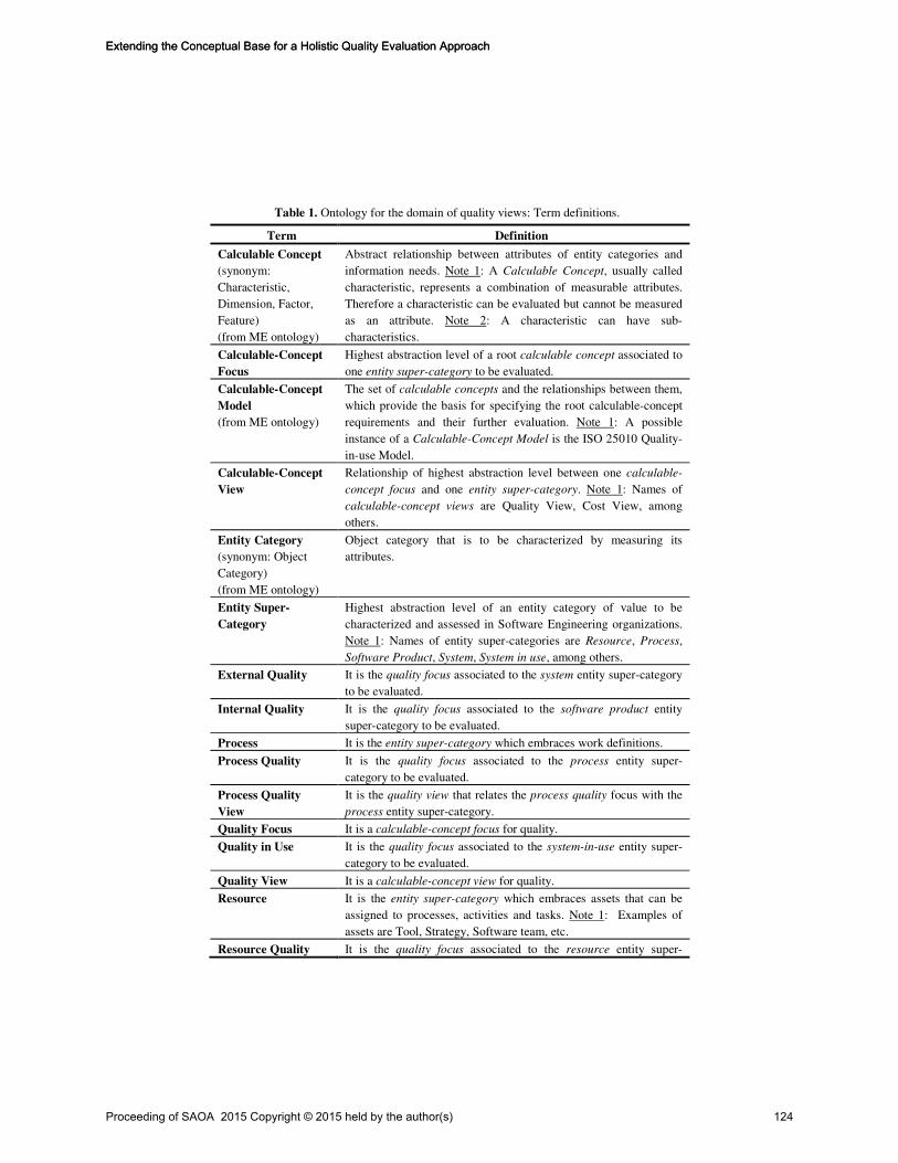
Table 1. Ontology for the domain of quality views: Term definitions.
Term Definition
Calculable Concept
(synonym:
Characteristic,
Dimension, Factor,
Feature)
(from ME ontology)
Abstract relationship between attributes of entity categories and
information needs. Note 1: A Calculable Concept, usually called
characteristic, represents a combination of measurable attributes.
Therefore a characteristic can be evaluated but cannot be measured
as an attribute. Note 2: A characteristic can have sub-
characteristics.
Calculable-Concept
Focus
Highest abstraction level of a root calculable concept associated to
one entity super-category to be evaluated.
Calculable-Concept
Model
(from ME ontology)
The set of calculable concepts and the relationships between them,
which provide the basis for specifying the root calculable-concept
requirements and their further evaluation. Note 1: A possible
instance of a Calculable-Concept Model is the ISO 25010 Quality-
in-use Model.
Calculable-Concept
View
Relationship of highest abstraction level between one calculable-
concept focus and one entity super-category. Note 1: Names of
calculable-concept views are Quality View, Cost View, among
others.
Entity Category
(synonym: Object
Category)
(from ME ontology)
Object category that is to be characterized by measuring its
attributes.
Entity Super-
Category
Highest abstraction level of an entity category of value to be
characterized and assessed in Software Engineering organizations.
Note 1: Names of entity super-categories are Resource, Process,
Software Product, System, System in use, among others.
External Quality It is the quality focus associated to the system entity super-category
to be evaluated.
Internal Quality It is the quality focus associated to the software product entity
super-category to be evaluated.
Process It is the entity super-category which embraces work definitions.
Process Quality It is the quality focus associated to the process entity super-
category to be evaluated.
Process Quality
View
It is the quality view that relates the process quality focus with the
process entity super-category.
Quality Focus It is a calculable-concept focus for quality.
Quality in Use It is the quality focus associated to the system-in-use entity super-
category to be evaluated.
Quality View It is a calculable-concept view for quality.
Resource It is the entity super-category which embraces assets that can be
assigned to processes, activities and tasks. Note 1: Examples of
assets are Tool, Strategy, Software team, etc.
Resource Quality It is the quality focus associated to the resource entity super-
Proceeding of SAOA 2015 Copyright © 2015 held by the author(s) 124
Extending the Conceptual Base for a Holistic Quality Evaluation ApproachExtending the Conceptual Base for a Holistic Quality Evaluation Approach
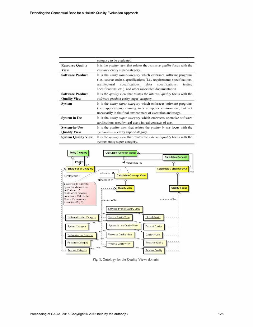
category
Resource Quality
View
It is the
resource
Software Product It is the
(i.e., source codes), specifications (i.e., requirements specifications,
architectural specifications, data specifications, testing
specifications, etc.), and other associated documentation.
Software Product
Quality View
It is the
software product
System It is the
(i.e., applications) running in a computer environment, but not
necessa
System in Use It is the
applications used by real users in real contexts of use.
System-in-Use
Quality View
It is the
system
System Quality View It is the
system
Fig. 1
category to be evaluated.
It is the quality view that relates the resource quality focus with the
resource entity super-category.
It is the entity super-category which embraces software programs
(i.e., source codes), specifications (i.e., requirements specifications,
architectural specifications, data specifications, testing
specifications, etc.), and other associated documentation.
It is the quality view that relates the internal quality focus with the
software product entity super-category.
It is the entity super-category which embraces software programs
(i.e., applications) running in a computer environment, but not
necessarily in the final environment of execution and usage.
It is the entity super-category which embraces operative software
applications used by real users in real contexts of use.
It is the quality view that relates the quality in use focus with the
system-in-use entity super-category.
It is the quality view that relates the external quality focus with the
system entity super-category.
1. Ontology for the Quality Views domain.
focus with the
which embraces software programs
(i.e., source codes), specifications (i.e., requirements specifications,
architectural specifications, data specifications, testing
focus with the
which embraces software programs
(i.e., applications) running in a computer environment, but not
which embraces operative software
focus with the
focus with the
Proceeding of SAOA 2015 Copyright © 2015 held by the author(s) 125
Extending the Conceptual Base for a Holistic Quality Evaluation ApproachExtending the Conceptual Base for a Holistic Quality Evaluation Approach

Table 2. Ontology for the
Relationship
depends on A calculable
influences A calculable
pertains An entity
represented_by A calculable
calculable concept models
Fig. 2.
Fig. 3. The quality_view component which extends the C
Note that many C-INCAMI components are drawn without terms for space reasons.
The quality views ontology
ontology [12]. Particularly, an
requirements component in Fig. 3
category that is to be characterized by measuring its
Calculable-Concept Focus
or more Calculable-Concept Model
Calculable-Concept Model
and the relationships between them, which provide the basis for specifying the root
calculable-concept requirements and their further evaluation
Ultimately, Fig. 3 shows the
those yellow-colored key terms in Fig. 1
Ontology for the domain of quality views: Relationship definitions.
Definition
alculable-concept view depends on other calculable-concept view.
alculable-concept view influences other calculable-concept view.
entity category can be classified into an entity super-category.
alculable-concept view can be represented by one or several
calculable concept models.
Fig. 2. An instantiation of typical quality views.
component which extends the C-INCAMI conceptual framework.
INCAMI components are drawn without terms for space reasons.
quality views ontology shares some terms with the previously developed ME
]. Particularly, an Entity Super-Category is an Entity Category –from the
component in Fig. 3-, which is defined in Table 1 as “the object
category that is to be characterized by measuring its attributes”. In turn, a
Concept Focus is a root Calculable Concept and it is represented by one
Concept Model –see the requirements component. A
Concept Model is defined in Table 1 as “the set of calculable concept
and the relationships between them, which provide the basis for specifying the root
concept requirements and their further evaluation”.
shows the added quality_view component –which includes
colored key terms in Fig. 1- and its linking with the non-functional
concept view.
can be represented by one or several
INCAMI conceptual framework.
ith the previously developed ME
from the
the object
”. In turn, a
one
component. A
the set of calculable concepts
and the relationships between them, which provide the basis for specifying the root
which includes
functional
Proceeding of SAOA 2015 Copyright © 2015 held by the author(s) 126
Extending the Conceptual Base for a Holistic Quality Evaluation ApproachExtending the Conceptual Base for a Holistic Quality Evaluation Approach

requirements component, which is one component of the C-INCAMI conceptual
framework. Note also that in Fig. 1 the terms belonging to the requirements
component are green colored as in Fig. 3.
3 Quality Views and Strategy Patterns: An Abridged Discussion
It is well-known that ontologies are widely used for different purposes [3] (e.g.,
natural language processing, knowledge management, information integration,
semantic web processing) in different communities (e.g., knowledge engineering,
web and software engineering). The previous Section has specified the ontology of
quality views which is paramount for defining ME and MEC strategy patterns [14].
A strategy pattern can be seen as a general reusable solution to recurrent
problems within given measurement, evaluation and change/improvement situations
for specific projects' goals. So, in the following paragraphs, we analyze some strategy
patterns that can be defined considering the type of ME/MEC project goal (e.g.
understand, change/improve) and the type and amount of quality views that can
intervene (recall Fig. 2), which can be one or more. It is worthy to remark that the
quality views ontology plays a central role in defining strategy patterns. That is,
without a clear specification of the terms and relationships for quality views, the
ulterior specification of strategy patterns could not be done appropriately.
Specifically, the quality views ontology fosters the specification and selection of
appropriate strategy patterns and their instantiation regarding different ME/MEC
project goals.
Usually, strategy patterns are documented by templates. In a previous work [14],
we have specified a set of strategy patterns following to some extent the pattern
specification template used in [5]. Our template includes the following items: (1)
name: A descriptive and unique name, usually expressed in English; (2) alias:
Acronym or other names for the pattern; (3) intent: Main objective for the pattern;
(4) motivation (problem): Problem which solves the pattern; (5) applicability:
Situations in which the pattern can be applied; (6) structure (solution): Generic
structure and instantiable solution that the pattern offers; (7) known uses: References
of real usage; (8) scenario of use: Concrete example and illustration for the
instantiated pattern.
As above mentioned, a strategy pattern must be selected according to the type of
ME/MEC project goal and the amount of involved quality views. In this sense, we
distinguish at least a set of six strategy patterns. Reassuming the example commented
in the Introduction, viz. ‘understand the usability of the current state of the XYZ
mobile application’, the ME project goal has an "understand" purpose embracing the
System Quality View (i.e., the Entity Super-Category is System and the Quality Focus
is EQ, where the concrete Entity is the "XYZ mobile application"). Therefore, a
strategy pattern that considers just one quality view for ME should be selected. In
[14], this strategy pattern is the so-called Goal-Oriented Context-Aware
Measurement and Evaluation for one Quality View (alias GOCAME_1V). Supposing
by a while that the project involves also a change (MEC) goal for one quality view, it
Proceeding of SAOA 2015 Copyright © 2015 held by the author(s) 127
Extending the Conceptual Base for a Holistic Quality Evaluation ApproachExtending the Conceptual Base for a Holistic Quality Evaluation Approach

is now necessary not only to understand the current situation of the entity but also to
perform changes on the entity in order to re-evaluate it and gauge the improvement
gain. This strategy pattern is named Goal-Oriented Context-Aware Measurement,
Evaluation and Change for one Quality View (alias GOCAMEC_1V). Both
GOCAME_1V and GOCAMEC_1V share the same amount of involved quality
views but they differ in the intended goal, i.e., while the former is intended mainly
for the "understand" goal the latter is for the "improve" goal.
On the other hand, if the project involves MEC goals but for two quality views
then the GOCAMEC_2V strategy pattern should be chosen. This strategy pattern
addresses the fact that improving one quality view from other quality view is
supported thanks to the influences and depends on relationships between quality
views. As can be seen in Fig. 2, the System Quality View influences the System-in-
Use Quality View, hence by evaluating and improving the EQ Focus of a System is
one means for improving the QinU Focus of a System in Use. Conversely, evaluating
the QinU can provide feedback to improve the EQ by exploring the depends on
relationship. A concrete strategy derived from this pattern is the so-called SIQinU
(Strategy for Improving Quality in Use). This strategy allows improving QinU from
the EQ standpoint, as documented in the industrial case presented in [9].
The GOCAMEC_2V strategy pattern can also be instantiated for other two related
quality views. For example, looking at Fig. 2 in which the resource quality (e.g., a
new integrated tool) influences the process quality (e.g., a development process) and
the process quality depends on the resource quality, GOCAMEC_2V should be
instantiated respectively for Resource and Process Quality Views.
Furthermore, regarding the mentioned relationships between views, strategy
patterns where three quality views intervene can be instantiated. For instance, we can
mention the GOCAMEC_3V strategy pattern where the Software Product, System
and System-in-Use Quality Views can be considered.
In summary, the modeling of many quality views and their relationships foster
developing a family of patterns. Patterns are essentially ‘experience in a can’, to our
case, ready to be opened and used by evaluators in quality assurance processes.
4 Related Work
In the literature review made about the few works that deal with the domain of
quality views, we have observed there is no research defining a quality views
ontology, nor an explicit glossary of terms. One of the most relevant works
previously mentioned is the ISO 25010 standard [7], where different quality views
and their ‘influences’ and ‘depends on’ relationships are presented informally in an
annex. It illustrates that the software lifecycle processes (such as the quality
requirements process, design process and testing process) influence the quality of the
software product and the system; the quality of resources, such as human resources,
software tools and techniques used for the process, influence the process quality, and
consequently, influence the product quality; among other influences relationships
between quality views. However, the explicit definition of the quality view term and
Proceeding of SAOA 2015 Copyright © 2015 held by the author(s) 128
Extending the Conceptual Base for a Holistic Quality Evaluation ApproachExtending the Conceptual Base for a Holistic Quality Evaluation Approach

the ‘influences’ and ‘depends on’ relationships are missing in its glossary. Moreover,
it is not a clear association between a quality focus and an entity category nor the
definitions of the different entity categories as we made in Table 1.
Other initiative related to quality views is [10] in which just the ‘influences’
relationship between EQ and QinU is determined by means of Bayesian networks,
taking as reference the ISO 9126 standard [8]. However, it does not present a
conceptual base in the context of a holistic quality evaluation approach as we propose.
Lastly, we can mention the 2Q2U (Internal/External Quality, Quality in Use,
Actual Usability, and User experience) quality framework [11]. This work extends the
quality models defined in [7] adding new sub-characteristics for EQ and QinU, and
considers the ‘influences’ and ‘depends on’ relationships for three quality views,
namely: Software Product, System and System-in-Use Quality Views. But an explicit
ontology for the quality views domain as we propose in this paper is missing.
In summary, there are no related works for the definition and specification of an
ontology of quality views. Moreover, there is no research that relates quality views'
terms with non-functional requirements' terms as we documented in Section 2.
However, there exists research about ontologies in software measurement, e.g., the
Software Measurement Ontology (SMO) [1], in which authors relate foundational
ontologies with domain ontologies. This clear separation of concern between generic
and domain ontologies will be dealt in a future for our ontology of quality views.
Finally, having well-defined quality views and their relationships provides the ba-
sis for a more robust selection of strategy patterns for ME/MEC project goals (as
commented in Section 3) and also contributes to enhance our quality evaluation ap-
proach.
5 Conclusions and Future Work
As commented in the Introduction Section, the architecture of our holistic quality
evaluation approach is built on two columns: (1) a quality multi-view modeling
framework, and (2) ME/MEC integrated strategies. One discussed contribution in
this work is the specification of the ontology of quality views, aimed at adding
robustness to our approach. To build this ontology we have reviewed the related
literature to the quality views domain. Specifically, we have observed that there is no
such an ontology, taxonomy or glossary for this domain.
Note that in this paper, we have addressed the ontology representation and a
possible instantiation of it rather than the ontology construction process itself.
Nevertheless, the stages proposed in the METHONTOLOGY [4] approach were
followed such as specification, conceptualization, formalization and integration. The
integration stage was done by relating the quality views ontology with the previous
C-INCAMI's ME ontology. This fulfills the second contribution stated in the
Introduction Section. As a consequence, the former conceptual base for the holistic
quality evaluation approach was enhanced.
Regarding the third stated contribution, we have analyzed in Section 3 the
importance of having well-defined quality views and their relationships with the aim
Proceeding of SAOA 2015 Copyright © 2015 held by the author(s) 129
Extending the Conceptual Base for a Holistic Quality Evaluation ApproachExtending the Conceptual Base for a Holistic Quality Evaluation Approach

of defining and selecting strategy patterns for different ME/MEC project goals.
As future work, we envision the development of a strategy pattern recommender
system as a practical use of the quality views ontology in the context of the holistic
quality evaluation approach. This system can be useful when an organization
establishes a ME/MEC project goal. So, taking into account the type of project goal
and the amount of involved quality views, the strategy pattern recommender system
will suggest the suitable strategy pattern that fits that goal.
References
1. Barcellos M.P., Falbo R. A., Dalmoro R.: A Well-Founded Software Measurement
Ontology. In 6th International Conference on Formal Ontology in Information Systems
(FOIS), pp. 213-226, (2010)
2. Becker P., Papa F., Olsina L.: Process Ontology Specification for Enhancing the Process
Compliance of a Measurement and Evaluation Strategy. In CLEI Electronic Journal 18(1),
pp. 1-26. ISSN 0717-5000, (2015)
3. Corcho O., Fernández-López M., Gómez-Pérez A.: Methodologies, tools and languages
for building ontologies. Where is their meeting point? Data & Knowledge Engineering
46(1), pp. 41–64, (2003)
4. Fernández-López M., Gómez-Pérez A., Juristo N.: METHONTOLOGY: From Ontological
Art Towards Ontological Engineering. Spring Symposium on Ontological Engineering of
AAAI, pp. 33–40, Stanford University, California, (1997)
5. Gamma E., Helm R., Johnson R., Vlissides J.: Design Patterns: Elements of Reusable
Object-Oriented Software. Addisson-Wesley, ISBN 0-201-63361-2, (1995)
6. Gruber T.R.: A Translation Approach to Portable Ontologies. Knowledge Acquisition,
5(2), pp. 199–220, (1993)
7. ISO/IEC 25010: Systems and software engineering - Systems and software Quality
Requirements and Evaluation (SQuaRE) - System and software quality models, (2011)
8. ISO/IEC 9126-1: Software Engineering Product Quality - Part 1: Quality Model (2001)
9. Lew P., Olsina L., Becker P., Zhang, L.: An Integrated Strategy to Systematically
Understand and Manage Quality in Use for Web Applications. Requirements Engineering
Journal, Springer London, 17( 4), pp. 299-330, (2012)
10. Moraga M.A, Bertoa M.F., Morcillo M.C., Calero C., Vallecillo A.: Evaluating Quality-in-
Use Using Bayesian Networks. In QAOOSE 2008, Paphos, Cyprus, pp 1-10, (2008)
11. Olsina L., Lew P., Dieser A., Rivera M.B.: Updating Quality Models for Evaluating New
Generation Web Applications. In Journal of Web Engineering, Special issue: Quality in
new generation Web applications, Abrahão S., Cachero C., Cappiello C., Matera M.
(Eds.), Rinton Press, USA, 11(3), pp. 209-246, (2012)
12. Olsina L., Papa F., Molina H.: How to Measure and Evaluate Web Applications in a
Consistent Way. HCIS Springer book Web Engineering: Modeling and Implementing Web
Applications; Rossi G., Pastor O., Schwabe D., and Olsina L. (Eds.), pp. 385-420, (2008)
13. OMG-UML. Unified Modeling Language Specification, Version 2.0. (2005)
14. Rivera M.B., Becker P., Olsina L.: Strategy Patterns for Measurement, Evaluation And
Improvement Projects (In Spanish). XVIII Iberoamerican Conference in Software
Engineering (CIbSE’15), Lima, Perú, pp. 166-180, ISBN: 978-9972-825-80-4, (2015)
15. van Heijst G., Schreiber A.T., Wielinga B.J.: Using Explicit Ontologies in KBS
Development. International Journal of Human-Computer Studies, 46, pp.183-292,
Academic Press, Inc. Duluth, MN,USA, (1997)
Proceeding of SAOA 2015 Copyright © 2015 held by the author(s) 130
Extending the Conceptual Base for a Holistic Quality Evaluation ApproachExtending the Conceptual Base for a Holistic Quality Evaluation Approach
Top Related