


Languages
Pages
Legal


USFD
Of Rail & Welds
Compiled By: N.C.Ram, Secy. to PCE / S.E.Rly.
Assisted by:
Shri S.Mitra, Dy.CE/Track/ S.E.Railway Shri S.C.Koley, XEN/Track/S.E.Railway
Shri T.K.Dey, SSE/PWay/USFD/S.E.Railway Shri G. Nageswar Rao, Jr. Clerk/GRC
ENGINEERING DEPARTMENT
South Eastern Railway 11, Garden Reach, Kolkata-43

In loving memory of Late Animesh Kr. Ganguly, ex.PCE./S.E.Rly.
This booklet is a tribute to the man whose legendary style,
exemplary commitment to work and humane approach in the workplace will continue to inspire the Railwaymen in many- many years to come.
The foreword is from him.

Foreword: USFD of rails and welds is one of the most important safety-related activities for officials connected with Permanent Way. Effective testing, monitoring, monitoring and prompt post-USFD measures will ensure that the flaw in rail and weld will get detected timely and removed before it causes disruption to the traffic or in a worst case scenario a derailment. With the view to increase the awareness of Field Staff in USFD and to ensure better check and monitoring this handy booklet has been prepared. The booklet contains the provision of USFD manual upto Correction Slip No.17/2006 and the CE circular No.253 supplemented with some basics on USFD. It is expected that the field staff use this booklet to further systematize the whole USFD activity. However, all officials using this booklet should note that this is only to aid the Field Staff and is in no way a replacement of the USFD Manual and Correction Slips issued from time to time.
(Animesh Kumar Ganguly)
Pr.CE/S.E.Rly. Note : The booklet needs to be updated by the user with issue of new instructions and
correction slip to USFD Manual. (iii)

Contents………….. S/ No.
Description Page No.
1. Introduction 12. History 1 3. Basic Principle 24. Theory of Ultrasound 3-11 5. Advantage of NDT by USFD 12 6. Source of Sound Waves 13-14 7. Equipment 15-178. Maintenance of machine 18 9. Calibration of USFD 19-26 10. Procedure for USFD 27-28 11. Limitation of USFD 29-33 12. Dos & Don’ts of USFD Testing 34-37 13. Record Keeping 38-3914. Check List 40-4115. Responsibilities 42-4416 New Developments in USFD 45-49 17. Glossary of important terms 50-52
(iv)
ANNEXURES S/ No.
Description Page No.
I. Testing method for Rails 53 I. Testing method for the Bolt-Holes (by SRT) 54-55 I. Method for initial acceptance test for new AT welds
(SRT or special Portable Machine) 56-57
I. Method for AT welds after Initial Acceptance test (SRT or Special Portable Machine)
58-61
II. Probes for USFD Testing of Rails (DRT) 62 II. Probes for USFD Testing the Bolt-Holes (SRT) 63-64 II. Probes for USFD Initial Acceptance Test for new
thermit welds (SRT or special portable machine) 65-66
II. Probes for testing thermit welds after Initial Acceptance Test (SRT or Special Portable Machine)
67-69
II. Area of scan with all probes combined 70 III. Action to taken after defect classification in need based criteria 71-72
Notes 73-75
(v)
1.0 Introduction:
Serviceability of engineering components can seriously suffer due to internal flaws. While some flaws are inherent others may be incipient during service. Objective of Engineers is to detect these flaws before they cause failure & disruption in service. Ideally, a technique, which can detect a flaw and its characterization without impairing the serviceability of the component, is required. Here the Non-Destructive Testing, or NDT in short, becomes the most apt technique. Among NDT technique Ultrasonic Testing, or USFD is ideally suitable for Railway application due to its superior penetrating power, high sensitivity, greater accuracy, instantaneous indication, simple on line interpretation and portability. Radiography, liquid penetration test, magnetic particle inspection, eddy current methods are some of the other popular NDT techniques which are used in other application.
2.0 History:
The pre-World War-II technique called SONAR to detect sub-marine objects by sending sound waves then analysing the back echoes was further customized to detect the flaws in metals by pulse-echo technique using ultrasound (sound wave beyond human audible range limit of 20 kHz). This technique is called USFD, which is one of the popular NDT techniques.
[1]
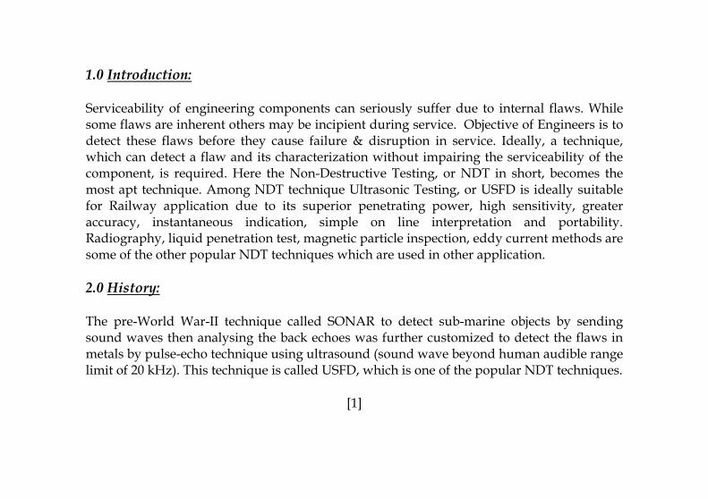
3.0 Basic Principle: It is Non-Destructive Test (NDT) technique using sound waves (Mechanical Vibrations) with frequency beyond audible range. The sound wave transmitted to solid is reflected back either from far surface or any reflector (Flaw) it encounters in between. The amount and time delay of reflected echo (displayed in CRT) is proportional to defect size and depth from surface. Reflected sound energy is displayed versus time, and the Inspector (Operator) can visualize a cross section of the specimen showing the depth of the features that reflects sound.
0 2
Pulse Energy
Initial Pulse
FlaEch‘A
Oscilloscop
Tim
RailFlaw
4 6 8 10
B A
Back Surface B
w o ’
e, or flaw detector screen
e Scale
Probe
Fig:1 Schematic Diagram of USFD Process.
[2]
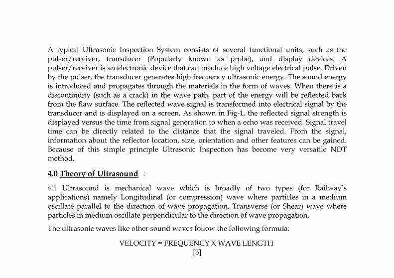
A typical Ultrasonic Inspection System consists of several functional units, such as the pulser/receiver, transducer (Popularly known as probe), and display devices. A pulser/receiver is an electronic device that can produce high voltage electrical pulse. Driven by the pulser, the transducer generates high frequency ultrasonic energy. The sound energy is introduced and propagates through the materials in the form of waves. When there is a discontinuity (such as a crack) in the wave path, part of the energy will be reflected back from the flaw surface. The reflected wave signal is transformed into electrical signal by the transducer and is displayed on a screen. As shown in Fig-1, the reflected signal strength is displayed versus the time from signal generation to when a echo was received. Signal travel time can be directly related to the distance that the signal traveled. From the signal, information about the reflector location, size, orientation and other features can be gained. Because of this simple principle Ultrasonic Inspection has become very versatile NDT method.
4.0 Theory of Ultrasound :
4.1 Ultrasound is mechanical wave which is broadly of two types (for Railway’s applications) namely Longitudinal (or compression) wave where particles in a medium oscillate parallel to the direction of wave propagation, Transverse (or Shear) wave where particles in medium oscillate perpendicular to the direction of wave propagation.
The ultrasonic waves like other sound waves follow the following formula:
VELOCITY = FREQUENCY X WAVE LENGTH [3]
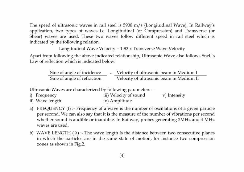
The speed of ultrasonic waves in rail steel is 5900 m/s (Longitudinal Wave). In Railway’s application, two types of waves i.e. Longitudinal (or Compression) and Transverse (or Shear) waves are used. These two waves follow different speed in rail steel which is indicated by the following relation.
Longitudinal Wave Velocity = 1.82 x Transverse Wave Velocity
Apart from following the above indicated relationship, Ultrasonic Wave also follows Snell’s Law of reflection which is indicated below:
Sine of angle of incidence Velocity of ultrasonic beam in Medium I Sine of angle of refraction
=
Velocity of ultrasonic beam in Medium II Ultrasonic Waves are characterized by following parameters : - i) Frequency iii) Velocity of sound v) Intensity ii) Wave length iv) Amplitude
a) FREQUENCY (f) :- Frequency of a wave is the number of oscillations of a given particle per second. We can also say that it is the measure of the number of vibrations per second whether sound is audible or inaudible. In Railway, probes generating 2MHz and 4 MHz waves are used.
b) WAVE LENGTH ( λ) :- The wave length is the distance between two consecutive planes in which the particles are in the same state of motion, for instance two compression zones as shown in Fig.2.
[4]
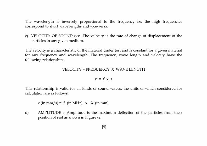
The wavelength is inversely proportional to the frequency i.e. the high frequencies correspond to short wave lengths and vice-versa.
c) VELOCITY OF SOUND (v):- The velocity is the rate of change of displacement of the particles in any given medium.
The velocity is a characteristic of the material under test and is constant for a given material for any frequency and wavelength. The frequency, wave length and velocity have the following relationship:-
VELOCITY = FREQUENCY X WAVE LENGTH
v = f x λ
This relationship is valid for all kinds of sound waves, the units of which considered for calculation are as follows:
v (in mm/s) = f (in MHz) x λ (in mm)
d) AMPLITUDE :- Amplitude is the maximum deflection of the particles from their position of rest as shown in Figure -2.
[5]

e) INTENSITY:- The intensity of sound is the energy transferred per second through unit surface of the wave.
4.2 WAVE LENGTH AND DIMENSION OF A GIVEN FLAW: - The wave length of Ultrasonic Waves gives an idea of the dimension of a given flaw which can be detected RELIABLY when using the particular frequency. Normally flaw sizes of more than λ/2 will get detected by a particular wave e.g. while carrying out ultrasonic testing of a steel component (speed=5900 m/s) at 2 MHz, using longitudinal waves (AT weld), the min. detectable flaw size will be approx. 1.5mm. Similarly, for 2MHz angle probes it will be 0.8 mm and 4 MHz normal probe it will be approximately 0.73 mm.
[6]

4.3 PROPERTIES OF SOUND WAVES: i) Reflection
ii) Refraction iii) Mode conversion or transformation. iv) Diffraction v) Absorption vi) Scattering
The last three properties cause loss of energy of sound wave which is also called Attenuation. Attenuation is proportional to D³f4 /v4 where; D = Average grain size of medium. f = Frequency of wave. v = Velocity of wave (i) REFLECTION OF SOUND: Waves of sound reaching the boundary surface of the medium are reflected in the same way as waves of light. The angles of incidence and reflection are equal. The vibrations of incident and reflected waves take place in the same medium as shown in Fig.3.
The characteristics that determine the amount of reflection is known as the specific Acoustic Impedance of the material and is a product of density and velocity i.e.
Acoustic Impedance = Density of the material (D) x Velocity (v) W = D x v
[7]

(ii) REFRACTION
If a sound wave strikes a plane interface at an angle of incidence to the perpendicular, it is refracted in to the second medium. A part of the incident wave is also reflected in the same medium, as shown in Fig3.
When the sound velocity of refracted wave in second medium is HIGHER than the sound velocity of incident longitudinal wave in first medium, the beam is refracted off the perpendicular. The reverse i.e. when the sound velocity of refracted wave in second medium is LOWER than the sound velocity of incident longitudinal wave in first medium, the beam is refracted towards the perpendicular.
(iii) TRANFORMATION
In contrast of optics, this phenomenon has been observed in case of transmission of sound waves from one medium to another i.e. transformation of one kind of wave to another kind of wave as shown in Fig.3. The Longitudinal Waves are transformed into Transverse Waves and vice-versa depending on the angles of incidence and refraction and velocity of sound waves in the material. This phenomenon is of considerable importance in Ultrasonic testing of materials. This is elaborated later.
[8]

(iv) DIFFRACTION
An ultrasonic wave passing near the edge of an object has a tendency to bend towards and around it. This being of wave is called diffraction. Ultrasonic signals that could normally be received at a certain point may be diverted by diffraction and received at some other point.
(v) ABSORPTION
It is commonly observed that sound produced inside a room does not last indefinitely. No doubt the walls, ceiling and floor continuously reflect the sound, but still, for some reason or the other, the sound dies away soon, even if all the doors and windows are closed. The sound is mostly absorbed. The absorption of sound can take place in two forms viz. absorption at the boundary and absorption in the medium.
(vi) SCATTERING
Scattering of Ultrasonic Waves result if the material is not strictly homogeneous. It contains boundaries on which the acoustic impedance changes abruptly because two materials of different density or sound velocity meet at these interfaces.
[9]

As mentioned in item (iii) above, Transformation or Mode conversion is an important phenomenon in USFD testing of material. In Railway’s context this is used for generation of Transverse Waves which is used in all Angle Probes. In USFD testing of materials the Angle Probes have better utility as these increase the area of scan. Transformation of sound wave leads to conversion of Longitudinal Waves into Longitudinal and Transverse Waves in both reflected and refracted media as indicated in Fig-3. The extent of this mode conversion will depend on the Acoustic Impendence of both the medium.
[10]
Fig-3 : Mode conversion of wave and usable range of probe angles.
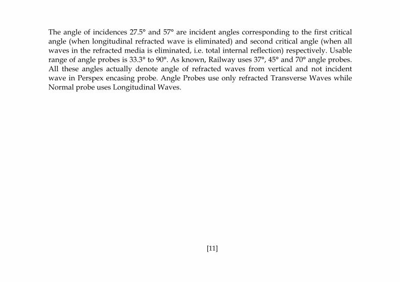
The angle of incidences 27.5° and 57° are incident angles corresponding to the first critical angle (when longitudinal refracted wave is eliminated) and second critical angle (when all waves in the refracted media is eliminated, i.e. total internal reflection) respectively. Usable range of angle probes is 33.3° to 90°. As known, Railway uses 37°, 45° and 70° angle probes. All these angles actually denote angle of refracted waves from vertical and not incident wave in Perspex encasing probe. Angle Probes use only refracted Transverse Waves while Normal probe uses Longitudinal Waves.
[11]

5.0 Advantages of NDT by USFD :
Some of the advantages of ultrasonic inspection that are often cited are:
• Instrument is portable and instant result is obtained. • The depth of penetration for flaw detection or measurement is superior to other NDT
methods. • It has high accuracy in determining reflector (flaw) position and estimating size and
shape. • Minimal part preparation required. • No consumable required except battery power and couplant, which is water for
Railway’s application.
[12]

6.0 Source of Sound Waves
The conversion of electrical pulses to mechanical vibrations and the conversion of returned mechanical vibrations back into electrical energy is the basis for ultrasonic testing. The active element is the heart of the transducer as it converts the electrical energy to acoustic energy, and vice versa. The active element is basically a piece polarized material (i.e. some parts of the molecule are positively charged, while other parts of the molecule are negatively charged) with electrodes attached to two of its opposite faces. When an electric field is applied across the material, the polarized molecules will align themselves with the electric field, resulting in induced dipoles within the molecular or crystal structure of the material. This alignment of molecules will cause the material to change dimensions. This phenomenon is known as electrostriction. In addition, a permanently-polarized material such as lead-zinconate-titanate or barium titanate (BaTiO3) will produce an electric field when the material changes dimensions as a result of an imposed mechanical force. This phenomenon is known as the piezoelectric effect. These crystal are fitted into the arrangement called probe. A schematic sketch diagram and cross section of Probe is shown in Fig-4 and 5 respectively.
[13]

Fig-4: Generation of waves in the crystal. Fig-5: Inverted Cross-Section of Normal Probe.
Types of Probes:
All probes used in IR are of Transmitter-Receiver type having lead-zinconate-titanate OR barium titanate synthetic piezo-electric crystal. Different types of probes and their combination for different machines (SRT or DRT) and application (Rail/Bolt-Hole/Weld testing) along with the area scanned by them is given in Annexure-II.
[14]

7.0 Equipment: Testing Equipment:
1. Single Rail Tester (SRT) (Conforming to M&C/NDT/103/2000)
i. Ultrasonic Flaw Detector. ii. Alarm Monitor. iii. Probes.
Transmitter-Receiver type probes of different angles having lead-zinconate-titanate OR barium titanate synthetic piezo-electric crystal.
iv. Co-axial Cables. v. Trolley. vi. Accessories. vii. Spares.
SNo. Item No 1 0° 4 MHz Double crystal probe 8 Nos. 2 70( ((F&B) Probe 2 MHz, Single crystal 8 Nos. 3 37( ((F&B) Probe 2 MHz, Single crystal 8 Nos. 4 45( 2 MHz Single crystal probe 2 Nos.
[15]
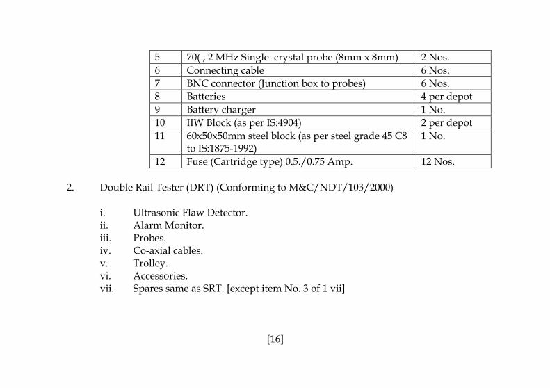
5 70( , 2 MHz Single crystal probe (8mm x 8mm) 2 Nos. 6 Connecting cable 6 Nos.7 BNC connector (Junction box to probes) 6 Nos. 8 Batteries 4 per depot 9 Battery charger 1 No. 10 IIW Block (as per IS:4904) 2 per depot 11 60x50x50mm steel block (as per steel grade 45 C8
to IS:1875-1992) 1 No.
12 Fuse (Cartridge type) 0.5./0.75 Amp. 12 Nos. 2. Double Rail Tester (DRT) (Conforming to M&C/NDT/103/2000)
i. Ultrasonic Flaw Detector. ii. Alarm Monitor. iii. Probes. iv. Co-axial cables. v. Trolley. vi. Accessories. vii. Spares same as SRT. [except item No. 3 of 1 vii]
[16]
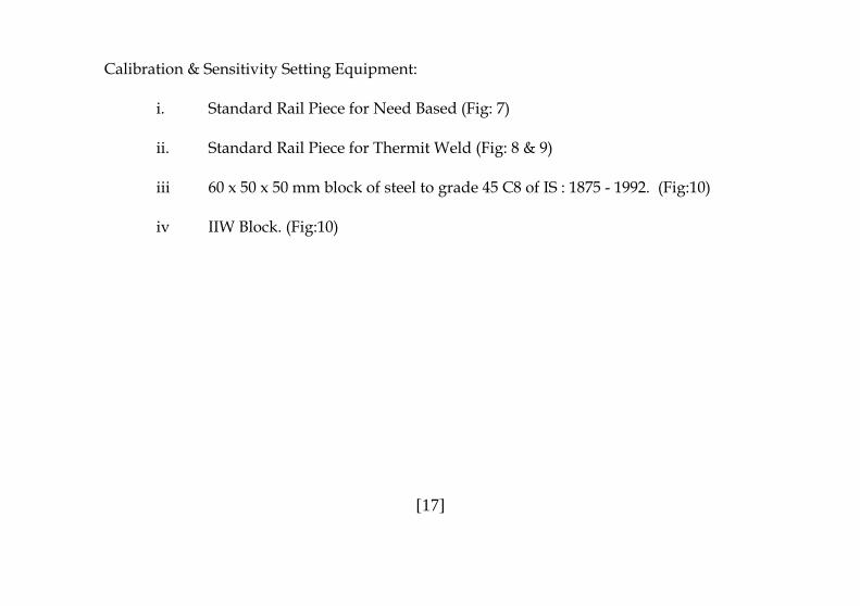
Calibration & Sensitivity Setting Equipment:
i. Standard Rail Piece for Need Based (Fig: 7)
ii. Standard Rail Piece for Thermit Weld (Fig: 8 & 9)
iii 60 x 50 x 50 mm block of steel to grade 45 C8 of IS : 1875 - 1992. (Fig:10)
iv IIW Block. (Fig:10)
[17]

8.0 Maintenance of machine :
• New machine has guarantee period of one year from the date of commissioning. • After expiry of the guarantee period of machine, Railway should make proper
arrangement for half yearly repairs of electronic and mechanical parts either under AMC with the manufacturer of the equipment or may develop suitable departmental facilities.
• Each Division should create centralized depots for carrying out mechanical repairs
and checking the Characteristics of the equipment etc. at least once in a month.
[18]

9. Calibration of USFD :
The ultrasonic rail tester is to be calibrated for 300 mm depth range (Longitudinal Wave) with the help of a 60 x 50 x 50 mm block of steel to grade 45 C8 of IS : 1875 - 1992. (a) Procedure of calibration
i. Switch on normal probe. (A typical CRT display and panel is in Fig:-6) ii. Adjust the on set of the surface echo from the Perspex of normal probe to zero by
using horizontal shift control knob/delay knob, provided in the electronic unit. iii. Place the calibration block below normal probe using water as couplant. iv. Adjust the range by H-shift/Delay and range control knob simultaneously so that
following signals appear on the screen. v. Location of signals for 300 mm depth has been indicated below. On set of the surface echo from the perspex at 0 main scale div.
60 mm signal at 1 main scale Horiz. Div. 120 mm signal at 2 main scale Horiz Div. 180mm signal at 3 main scale Horiz. Div. 240 mm signal at 4 main scale Horiz. Div. 300 mm signal at 5 main scale Horiz. Div. The equipment is now calibrated for 60 mm of steel per main scale horizontal div. for Longitudinal Wave.
[19]

(b) Sensitivity (Gain) setting of the equipment and probes: Weekly check - The
Sensitivity of USFD equipment shall be set up once in a week with the help of standard rail pieces as mentioned below
Sensitivity (Gain) setting: For the sensitivity setting of ultrasonic equipment and the probes the following sequence is to be maintained:
(i) Place the testing trolley on the standard rail piece having artificial flaws as shown in Fig. 7 for need based criteria (Conventional criteria is now abolished vide RDSO’s letter CT/USFD dated 18/19.9.06). Check the alignment of probes to make sure that they travel centrally in line with the axis of the rail head and web.
(ii) Set the acoustic barrier of the normal probe at right angle to the longitudinal direction of rail.
(iii) Adjust the gap of 0.2 mm approx. in between the contact face of the normal probe and the sole of probe shoe. Check the gap by keeping the straight edge of a 150 mm steel scale on the sole using a feeler gauge or a stainless steel blade.
(iv) Adjust the gap of the angle probes as in (iii) above.
(v) Open the water nozzle and regulate water flow on the probes at an optimum speed.
[20]

Fig:6 – A Typical CRT Screen & panel of SRT Machine
[21]

Fig: 7 – Standard Rail with artificial flaws (Need based criteria)
[22]

Fig: 8- Standard A.T. Weld rail piece with artificial flaws (25mm gap)
[23]

Fig: 9- Standard A.T.Weld (75mm gap) rail piece with artificial flaw.
[24]

Fig: 10-USFD m/c and calibration block
SRT USFD Machine DRT USFD Machine
IIW Block
Calibration BlockSteel step gauge
[25]

Angle probe (F&B) Angle Probe (F&B)
Normal Probe Fig:11-Photograph of different probes.
Single crystal Angle Probe
Single crystal Normal ProbeBNC Cable
[26]

10.0 Procedure for USFD :
USFD operators must adhere to the following instructions:
● Before testing
• Check the battery condition as indicated by the voltage needle or indicator lamp of USFD (or ascertain the voltage with the help of a voltmeter). Only fully charged batteries are to be used during testing.
• Check proper functioning of all control knobs of electronic unit i.e. depth range, gain, reject, etc.
• Check proper functioning of trolley and probes.
• Check junction box, water outlet, probe cable contact and ensure smooth movement of trolley wheels.
• Maintain proper gap between probing face and probe shoe (0.2 mm). Check with the help of a feeler gauge.
• Check probe alignment by keeping the rail tester on the rail.
• Calibrate the instrument everyday before conducting ultrasonic test. Set the depth range to 300 mm / 250 mm with the help of 60mm /50mm steel cube (Five echoes shall be observed on CRT).
[27]
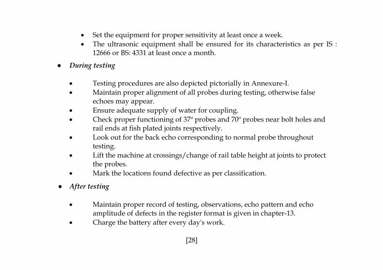
• Set the equipment for proper sensitivity at least once a week. • The ultrasonic equipment shall be ensured for its characteristics as per IS :
12666 or BS: 4331 at least once a month.
● During testing
• Testing procedures are also depicted pictorially in Annexure-I. • Maintain proper alignment of all probes during testing, otherwise false
echoes may appear. • Ensure adequate supply of water for coupling. • Check proper functioning of 37º probes and 70º probes near bolt holes and
rail ends at fish plated joints respectively. • Look out for the back echo corresponding to normal probe throughout
testing. • Lift the machine at crossings/change of rail table height at joints to protect
the probes. • Mark the locations found defective as per classification.
● After testing
• Maintain proper record of testing, observations, echo pattern and echo amplitude of defects in the register format is given in chapter-13.
• Charge the battery after every day's work.
[28]
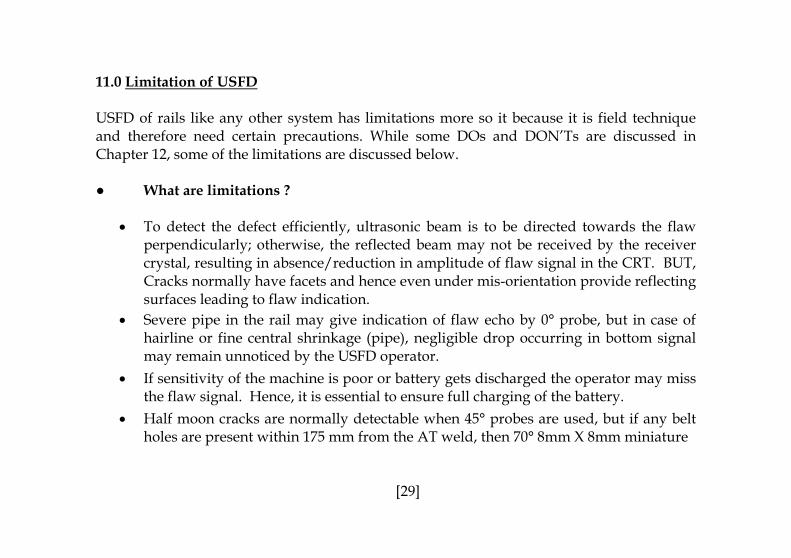
11.0 Limitation of USFD USFD of rails like any other system has limitations more so it because it is field technique and therefore need certain precautions. While some DOs and DON’Ts are discussed in Chapter 12, some of the limitations are discussed below. ● What are limitations ?
• To detect the defect efficiently, ultrasonic beam is to be directed towards the flaw perpendicularly; otherwise, the reflected beam may not be received by the receiver crystal, resulting in absence/reduction in amplitude of flaw signal in the CRT. BUT, Cracks normally have facets and hence even under mis-orientation provide reflecting surfaces leading to flaw indication.
• Severe pipe in the rail may give indication of flaw echo by 0° probe, but in case of hairline or fine central shrinkage (pipe), negligible drop occurring in bottom signal may remain unnoticed by the USFD operator.
• If sensitivity of the machine is poor or battery gets discharged the operator may miss the flaw signal. Hence, it is essential to ensure full charging of the battery.
• Half moon cracks are normally detectable when 45° probes are used, but if any belt holes are present within 175 mm from the AT weld, then 70° 8mm X 8mm miniature
[29]

probes are to be used. During the testing with these miniature probes, some of the half moon cracks may remain undetected which would otherwise normally be detected by 45° probes as the use of the miniature probes depends upon the accuracy of the operator.
• The ultrasonic probes used in the rail testers have a frequency of 4MHz (Longitudinal Wave) and 2 MHz (transverse waves). Therefore, cracks lesser than 0.73 mm (0.8 mm for Longitudinal Wave) size cannot be detected by the present arrangement.
• Rails having rust, pitting, hogging, battering of rail end, misalignment of joints, scabs, wheel burns and other surface imperfections restrict proper acoustic coupling between probe and rail table and may not permit detection of flaws. When ever such defects are encountered, loss of back wall echo or an alarm signal is obtained. This indicates that defects if any below these patches may remain undetected. Under such circumstances hand probing may be done.
• Due to special shapes except the stock rail, the balance portion of point and crossing is not amenable for detection by USFD trolley. Under such circumstances, hand probing is required to be carried out according to the procedure laid down in the manual for points and crossing or in the USFD manual.
• Since the testing of SEJ, Points and crossings specially in the nose portion poses practical problems during USFD examination of the track, it is essential to carry out
[30]

thorough testing of these items before they are put in to service and also before they are taken up for reclamation.
• In the event of dimensional variations in the gauge and also at sharp curves it is
possible that the probes are not properly contacting the rail surface. This is indicated by loss of backwall echo or also by alarm provided in DRTs for backwall drop. Wherever it is not possible to ensure proper acoustic coupling due to these reasons, testing by hand probing or by single rail tester may be resorted to.
• There is no proper indication whether the angular probes are functioning properly or
whether proper acoustic coupling is present. ● What are not limitations ?
• Half moon cracks defects in webfoot junction in AT welds as now these can be detected by 45º probe from rail top table OR 70º miniature probe.
• Vertical defects in web portion etc. are no longer limitations of the USFD equipments
since in the newly developed equipment special probes have been provided for detection of these defects.
• For detection of defects originating from Gauge Face Corner, a dedicated test set-up
has been developed. This set-up incorporates three 70° probes covering approx. the full width of the rail head and a set of two 45° probes. A defect located at 5mm from the corner is detectable using this equipment.
[31]

• For detection of bolt hole cracks, 37° probe have been provided. This is because the cracks emanating from bolt holes are generally oblique and propagate in the zig-zag manner. However, bolt hole cracks (especially horizontal ones) are also detectable by using 0° probe since they obstruct the path of sound waves and lead to drop/loss of back wall echo.
37° probes have been provided both in forward and backward direction. Forward probes detect defects in 2nd and 4th quadrant where as back ward probes detect cracks in 1st and 3rd quadrant. At fish plated joint, star cracks from 2nd quadrant of first bolt hole are not favourably oriented and hence, detection may not be possible (rail end cuts the beam from 37° backward probe). Similarly, if the cracks are propagating vertically downwards or upwards, detection is not possible. In case of double rail testers which do not have 37° probes, detection of few favourably oriented flaws is possible by 0° probe.
Conclusion:
• For detection of defects in rails, probes having incidence angle 0°, 70° (F), 70° (B), 37° (F), and 37° (B) have been provided in the USFD trolley. The angles have been chosen in a manner so as to detect defects which are generally observed during service and have been the cause of rail fractures.
[32]

• All commonly observed defects in rails are detectable by the above arrangement. In
the event of gross mis-orientation of defect at times it may not be amenable for detection, however such situations are rare.
In general ultrasonic inspection technique like other NDT techniques also has its limitations, which include:
• Skill and training should be more extensive than with some other methods.
• It normally requires a coupling medium to promote transfer of sound energy into
test specimen.
• Materials that are rough, irregular in shape, very small, exceptionally thin or not
homogeneous are difficult to inspect.
• Cast iron and other coarse-grained materials are difficult to inspect due to low sound
transmission and high signal noise.
• Linear defects oriented parallel to the sound beam may go undetected.
• Reference standards are required for both equipment calibration, and
characterization of flaws.
[33]
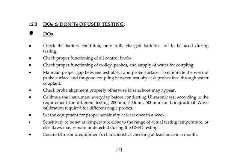
12.0 DOs & DON’Ts OF USFD TESTING:
● DOs ● Check the battery condition, only fully charged batteries are to be used during
testing.
● Check proper functioning of all control knobs.
● Check proper functioning of trolley, probes, and supply of water for coupling.
● Maintain proper gap between test object and probe surface. To eliminate the wear of probe surface and for good coupling between test object & probes face through water couplant.
● Check probe alignment properly otherwise false echoes may appear.
● Calibrate the instrument everyday before conducting Ultrasonic test according to the requirement for different testing 200mm, 300mm, 500mm for Longitudinal Wave calibration required for different angle probes.
● Set the equipment for proper sensitivity at least once in a week.
• Sensitivity to be set at temperature close to the range of actual testing temperature, or else flaws may remain undetected during the USFD testing.
● Ensure Ultrasonic equipment’s characteristics checking at least once in a month.
[34]
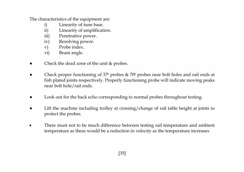
The characteristics of the equipment are:
i) Linearity of tune base. ii) Linearity of amplification. iii) Penetrative power. iv) Resolving power. v) Probe index. vi) Beam angle.
● Check the dead zone of the unit & probes. ● Check proper functioning of 370 probes & 700 probes near bolt holes and rail ends at
fish plated joints respectively. Properly functioning probe will indicate moving peaks near bolt hole/rail ends.
● Look out for the back echo corresponding to normal probes throughout testing. ● Lift the machine including trolley at crossing/change of rail table height at joints to
protect the probes. • There must not to be much difference between testing rail temperature and ambient
temperature as these would be a reduction in velocity as the temperature increases
[35]

resulting in beam angle increase. The sensitivity of machine is inversely proportional to temperature increase.
● After sensitivity setting the machine should be locked since IMR & OBS classification
will depend on oscillograph pattern at a particular sensitivity setting. If altered then it will lead to wrong classification.
• Do testing in some temperature at which sensitivity set as any flaw IMR/OBS in low
temperature may not show flaw in high temperature. • Only matching probes are to be used when procurement is done and it should be
from original equipment manufacturer or approved firm.
[36]

DON’Ts
● Don’t use discharged battery. ● Don’t overuse BNC connector as it will lead to loose connection. ● Don’t use the spares from local market or unauthorized/firms. ● Don’t alter sensitivity setting during testing. ● Don’t use sensitivity setting of rail testing for weld testing and vice versa. ● Don’t use co-axial wires longer than 5m. ● Don’t do weld testing without scraped and cleaned surface in flange or head (GF or
NGF).
• Don’t use Probe whose angle differs + 2° (As during passage of service probe angle changes).
• Don’t use DRT for through Testing of Rails where sharper curves in pts & Xings as well as Fish Plated zones. Testing at these locations should be by SRT only.
[37]

13. Record Keeping By USFD Operator
• Maintain proper record of testing, observations, echo pattern and echo amplitude of defects in the register in following format.
Classi- fication
Section Dateof testing
S. No
Loca- tion (Km)
TP No.
Rail No. L/R
Defect position (head/ web/ foot)
Defect indicated by (0°/70°/ 37°/45°)
Nature of echo (shift/ fixed)
Echo amplitude
IMR OBS DFW BMC
(Below marking criteria)
Re- marks
[38]
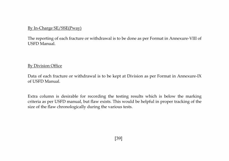
By In-Charge SE/SSE(Pway)
The reporting of each fracture or withdrawal is to be done as per Format in Annexure-VIII of USFD Manual.
By Division Office Data of each fracture or withdrawal is to be kept at Division as per Format in Annexure-IX of USFD Manual. Extra column is desirable for recording the testing results which is below the marking criteria as per USFD manual, but flaw exists. This would be helpful in proper tracking of the size of the flaw chronologically during the various tests.
[39]

14.0 Check list The checking of USFD is of two types, one is technical detailed checking and another is general USFD working. Both are detailed below. Sl.No.
Inspecting Official
Designation of Officer
Periodicity Format ofthe check
list
Authority
1 Technicalcontrolling officer of PWI/USFD
DEN/AEN In-charge at Division
Once in between two successive half yearly maintenance.
Annexure-XIII of USFD Manual
Para-4.3.1 of USFD Manual.
2 Officialinspecting the quality of work being done by USFD inspectors.
i) AEN/OL Sample check of the working of PWI/USFD. At least two hours each month during his routine trolley inspection should be spent with USFD team for cross checking the working including accuracy, setting/calibration of USFD machine.
Annexure-X of USFD Manual
Para-4.3 & RB’s letter 2003/CE-II/ PRA/s(CRS) dated 5.02.04.
[40]
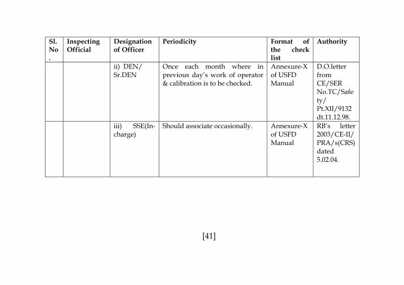
Sl.No.
Inspecting Official
Designation of Officer
Periodicity Format ofthe check list
Authority
ii) DEN/ Sr.DEN
Once each month where in previous day’s work of operator & calibration is to be checked.
Annexure-X of USFD Manual
D.O.letter from CE/SER No.TC/Safety/ Pt.XII/9132 dt.11.12.98.
iii) SSE(In-charge)
Should associate occasionally. Annexure-Xof USFD Manual
RB’s letter 2003/CE-II/ PRA/s(CRS) dated 5.02.04.
[41]
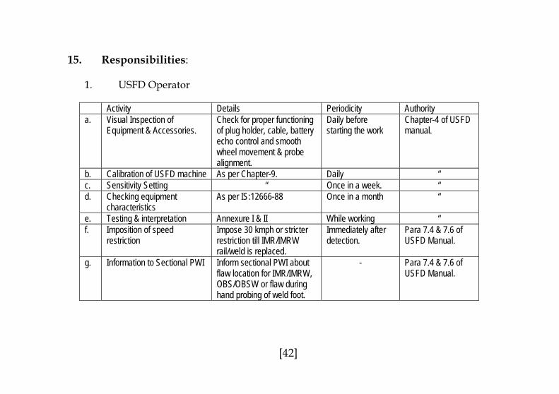
15. Responsibilities:
1. USFD Operator Activity Details Periodicity Authoritya. Visual Inspection of
Equipment & Accessories. Check for proper functioning of plug holder, cable, battery echo control and smooth wheel movement & probe alignment.
Daily before starting the work
Chapter-4 of USFD manual.
b. Calibration of USFD machine As per Chapter-9. Daily “ c. Sensitivity Setting “ Once in a week. “ d. Checking equipment
characteristics As per IS:12666-88 Once in a month “
e. Testing & interpretation Annexure I & II While working “ f. Imposition of speed
restriction Impose 30 kmph or stricter restriction till IMR/IMRW rail/weld is replaced.
Immediately after detection.
Para 7.4 & 7.6 of USFD Manual.
g. Information to Sectional PWI Inform sectional PWI about flaw location for IMR/IMRW, OBS/OBSW or flaw during hand probing of weld foot.
- Para 7.4 & 7.6 of USFD Manual.
[42]

2. Sectional PWI
To ensure the following after receiving information about detection of flaw from PWI/USFD.
• IMR/IMRW - Provide clamped joggle fish plate within 24 hrs. of detection till then post a watchman.
• OBS/OBSW - Advise Keyman to watch during daily patrolling till it is joggle fish plated.
● - (i) Protection of defective weld by joggled fishplates using minimum two tight clamps/2 far end tight bolts one on each side and relax speed up to 75 Kmph for goods train & 100 Kmph for passenger trains.
(ii) In case the protection of weld has been done using joggled fishplates with clamps, the defective weld shall be replaced within 15 days. However, in case the protection has been done using joggled fish plates with 2 far end tight bolts, the speed restriction imposed in (i) above shall continue till the defective weld is replaced which should not be later than 3 months. The defective weld with speed restriction as (i) above may be continued in track if the track is to be renewed within 12 months
* With 0º 2MHz, 70º 2MHz, 45º 2MHz OR 70º 2MHz (8mmx8mm) Probes.
[43]
DFW while periodic test of AT Weld*

3. In-Charge SE/SSE(Pway)
• General monitoring of post USFD activities by sectional PWI. • Occasionally check USFD operator’s work.
4. ADEN • Sample Checking of the working of PWI/USFD during the push trolley inspection of
the section. At least two hours per month. 5. Sr.DEN/DEN
• Sample checking of working of PWI/USFD at least once in a month.
6. Division • Planning of the USFD • Mechanical repairs of machine and checking characteristics of USFD equipments
every month. 7. XEN/TT/Sini & Dy.CE/TM/GRC
• Half yearly repairs of electronic and mechanical parts of machines. • Procurement of probes, batteries, spares etc. • Sample check of batteries by voltmeter & date of manufacturing to be checked &
recorded at the time of receipt at SINI Workshop. • Probes to be sample checked for proper functioning & proper angle.
8. HQ
• Procurement of machines. • Issue of policy guidelines. • Training of USFD operators and their man power planning.
[44]

16. New Developments in USFD: 16.1 Gauge Corner Flaw-Detection by Shifted 70º Probe. Due to introduction of higher tractive efforts by locomotives, higher UTS rails & higher axle loads of late Gauge Corner Defects have gained importance particularly in higher GMT routes. These flaws first appear as the “Head Checks” near the wheel contact area in the direction of traffic (Fig.12). Subsequently the failure is caused and the failed surface will have flaw as shown in the Fig.13 & Fig 14.
These flaws will require scanning by 70° hand probe (Scanned area as shown in Fig. 15) or by 70° F/B probe running on rail top table at a laterally shifted location towards gauge face by 8-10 mm. Alternatively, Scanning can be done by specially designed equipment. RDSO has issued the specification for such equipment vide M&C/NDT/121/2001. But till such time such equipment is made available the scanning by shifted 70° F/B probe is to be done. Scanning for Gauge Corner Defects shall be same as need based testing frequency in CC+8+2t and CC+6+2t routes and at least one round in a year in other routes (Before winter).
[45]

Fig: 12- ‘Head Checks’ near gauge face. Wheels travelling left to right.
Fig: 13- Small Gauge Corner Fatigue Failure
Fig: 14- Large Gauge Cor
5 mm
ner Fatigue Failure Fig: 15- Area covered by Gauge Face Corner Detection Equipment
[46]
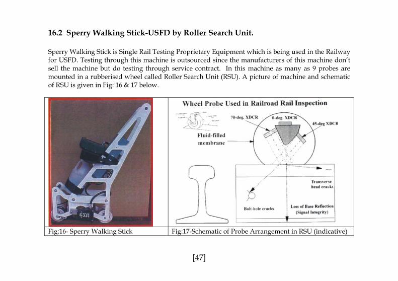
16.2 Sperry Walking Stick-USFD by Roller Search Unit. Sperry Walking Stick is Single Rail Testing Proprietary Equipment which is being used in the Railway for USFD. Testing through this machine is outsourced since the manufacturers of this machine don’t sell the machine but do testing through service contract. In this machine as many as 9 probes are mounted in a rubberised wheel called Roller Search Unit (RSU). A picture of machine and schematic of RSU is given in Fig: 16 & 17 below.
Fig:16- Sperry Walking Stick Fig:17-Schematic of Probe Arrangement in RSU (indicative)
[47]

A comparison of USFD by conventional machine and Sperry Walking Stick is given below: Item Conventional Machine Sperry Walking Stick No. of Probes 7 types of commonly used probes
in combination as detailed in Annexure-II.
9 probes in single run (3 Forward & 3 Backward 70º, 1 Forward & 1 Backward 37º and 1 0º Probe).
Probe Arrangement Flat faced and sliding type Mounted on tyred wheel and filled up with liquid.
Display CRT ( A-Scan) LCD ( A-Scan) Single Rail/ Double Rail Testing
Single OR Double. Always Single
Couplant Water WaterCalibration By IIW Block. By Steel Block having 5mm Ø 10mm
deep Flat Bottomed Hole inclined at 20º from horizontal.
Periodicity As indicated in Annexure-I. Equivalent to one round of normal testing. Hand probing of thermit weld to be done separately.
Area Scanned Approx. 83 % of Head (including 2 runs with shifted probe) + 100% of the web and bottom flange falling below web region+ Almost 100% of Flange by hand probing as shown in Fig.18.
94 % of Head+ 100% of the web cross sectional area and bottom flange of rail falling below web region as shown in Fig.19.
Limitations At best only 83% of head covered No flange testing of welds.
[48]

Fig: 18-Total area scanned by Conventional Machine with all probes (Rail & Weld).
Fig:19-Scanned area in RSU type Sperry Walking Stick.
45˚/70˚ Hand Probe
70˚Hand Probe
37˚
0˚
70˚
70˚Hand Probe For Gauge Face Detection
[49]

17. GLOSSARY OF IMPORTANT TERMS (Definitions as per IS:2417-1977) Acoustic Impedance: The product of the density and the velocity of sound in a medium. It is also called ‘characteristic impedance’. Angle of Incidence: The angle between the axis of the incident wave (or ray or beam) and the normal to the surface of incidence at the point of incidence. Angle of Reflection: The angle between the axis of the reflected wave (or ray or beam) and the normal to the reflecting surface at the point of reflection. Angle of refraction: The angle between the axis of the refracted wave (or ray or beam) and the normal to the refracting surface at the point of refraction. Angle Probe: A contact probe from which ultrasonic wave propagates at any angle other than ‘0’ degree and 90 degree to the normal to the tangent plane to the surface at the place where probe is positioned. Attenuation: The loss of intensity or energy of an ultrasonic wave during its passage through a medium due to the combined effects of absorption, beam spread and scattering.
[50]

Back Echo: Echo from the surface opposite to the scanning surface. It is also called ‘back reflection’, bottom reflection or ‘bottom echo’. Blind Area: Region just below the surface of the specimen from where the reflected pulse from a flaw cannot be separated from the transmitted purse. It is also called ‘dead zone’. Calibration: Properly establishing or determination of settings of an instrument with the help of a standard so as to obtain appropriate indication on cathode ray oscilloscope or other output signal. Couplant: A liquid or semi-solid interposed between the probe and the object to enable to enhance the transmission of ultrasonic energy between them. Echo: Reflected ultrasonic signal displayed on the cathode ray tube or the ultrasonic signal returned with sufficient magnitude and delay. Lead Zirconate Titanate(PZT): One of the piezoelectric materials commonly used in ultrasonic transducers. Mode conversion: Process by which waves of a given mode of propagation generates waves of other modes of propagation by reflection of refraction. It is also called ‘mode transformation’.
[51]
Normal Probe: A probe from which the ultrasonic beam emerges between 5° to normal to its face. It is also called ‘straight probe’. Pulse Echo technique: A technique in which the quality of a material is assessed by the reflection of pulses from discontinuities or back surface. Scattering: The irregular reflection from uneven or distributed boundaries like grain boundaries, group of pores etc. Transducer, Ultrasonic: A device which transforms electrical energy into ultrasonic energy and vice verse. Ultrasonics: The general subject of sound in the frequency range about the hearing range of the normal human ear and includes all those waves of frequency more than 20000 Hz.
[52]
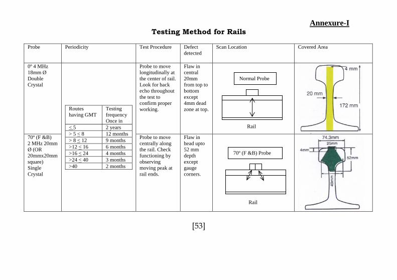
Annexure-I Testing Method for Rails
Probe Periodicity Test Procedure Defect
detected Scan Location Covered Area
0º 4 MHz 18mm Ø Double Crystal
Probe to move longitudinally at the center of rail. Look for back echo throughout the test to confirm proper working.
Flaw in central 20mm from top to bottom except 4mm dead zone at top.
70º (F &B) 2 MHz 20mm Ø (OR 20mmx20mm square) Single Crystal
Routes having GMT
Testing frequency Once in
< 5 2 years > 5 < 8 12 months > 8 < 12 9 months >12 < 16 >16 < 24 >24 < 40 >40
Normal Probe
Rail
Probe to move centrally along the rail. Check
Flaw in head upto 52 mm
70º (F &B) Probe
6 months
4 months 3 months 2 monthsfunctioning by observing moving peak at rail ends.
depth except gauge corners.
Rail
[53]
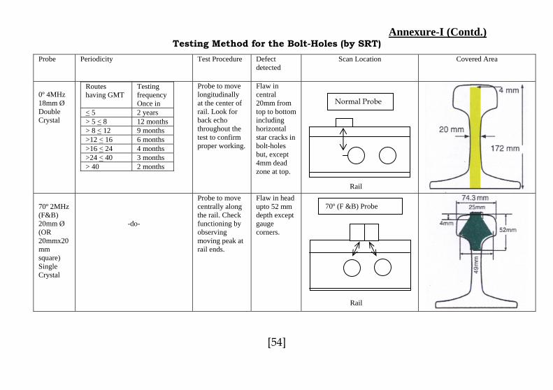
Annexure-I (Contd.) Testing Method for the Bolt-Holes (by SRT)
Probe Periodicity Test Procedure Defectdetected
Scan Location Covered Area
0º 4MHz 18mm Ø Double Crystal
Routes having GMT
Testing frequency Once in
< 5 2 years > 5 < 8 12 months > 8 < 12 9 months >12 < 16 6 months >16 < 24 4 months >24 < 40 3 months > 40 2 months
Probe to move longitudinally at the center of rail. Look for back echo throughout the test to confirm proper working.
Flaw in central 20mm from top to bottom including horizontal star cracks in bolt-holes but, except 4mm dead zone at top.
70º 2MHz (F&B) 20mm Ø (OR 20mmx20mm square) Single Crystal
-do-
Probe to move centrally along
Flaw in head upto 52 mm
Normal Probe
Rail
70º (F &B) Probe
the rail. Check functioning by observing moving peak at rail ends.
depth except gauge corners.
Rail
[54]

Annexure-I (Contd.)
Probe Periodicity Test Procedure Defectdetected
Scan Location Covered Area
37º 2 MHz (F&B) 20mmx20mm square Single Crystal.
-do-
To be moved on either side of the rail joint on the rail top table.
Star cracks from bolt holes.
37º (F &B)
Rail
[55]
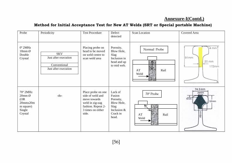
Annexure-I(Contd.)
Method for Initial Acceptance Test for New AT Welds (SRT or Special portable Machine)
Probe Periodicity Test Procedure Defectdetected
Scan Location Covered Area
0º 2MHz 18mm Ø Double Crystal
SKV Just after execution
Conventional
Just after execution
Placing probe on head to be moved on weld centre to scan weld area
Porosity, Blow Hole, Slag Inclusion in head and up to mid web.
70º 2MHz 20mm Ø (OR 20mmx20mm square) Single Crystal
-do-
Place probe on one side of weld and move towards weld in zig-zag fashion. Repeat 2-3 times on either side.
Lack of Fusion Porosity, Blow Hole, Slag Inclusion & Crack in head.
Normal Probe
AT Weld
Rail
70º Probe
Rail AT Weld
[56]
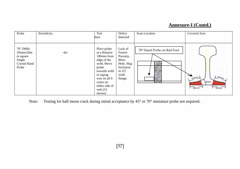
Annexure-I (Contd.)
Probe Periodicity Testdure
Defect detected
Scan Location Covered Area
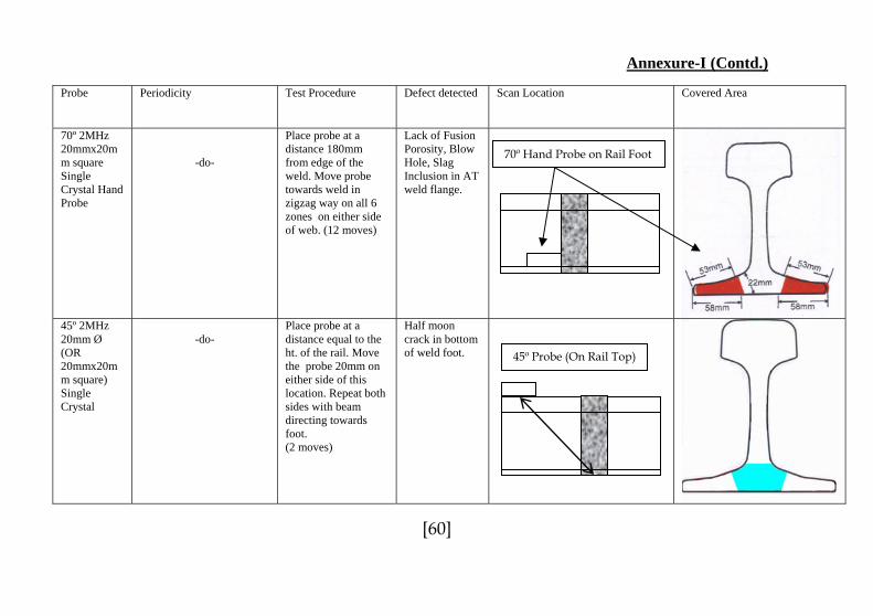
70º 2MHz 20mmx20mm square Single Crystal Hand Probe
-do-
Place probe at a distance 180mm from edge of the weld. Move probe towards weld in zigzag way on all 6 zones on either side of web (12 moves)
Lack of Fusion Porosity, Blow Hole, Slag Inclusion in AT weld flange.
70º Hand Probe on Rail Foot
Note: Testing for half moon crack during initial acceptance by 45° or 70° miniature probe not required.
[57]

Annexure-I (Contd.) Method for AT Welds after Initial Acceptance Test (SRT or Special Portable Machine)
Probe Periodicity Test
Procedure Defect detected
Scan Location Covered Area
0º 2MHz 18mm Ø Double Crystal
Type of Welds
Type of Testing
Testing Schedule
First Periodic Test
On completion of one year service life by weld
Conventional AT
Subsequent Periodic Tests
Every 40 GMT after First Periodic Test
First Periodic Test
1 year
Routeshaving GMT
Frequency
> 45 2 years > 30 < 45 3 years > 15 < 30 4 years
SKV
Further tests based on route GMT
0-15 5 years
Placing probe on head to be moved on weld centre to scan weld area
Porosity, Blow Hole, Slag Inclusion in head and up to mid web.
Normal Probe
Rail AT Weld
[58]
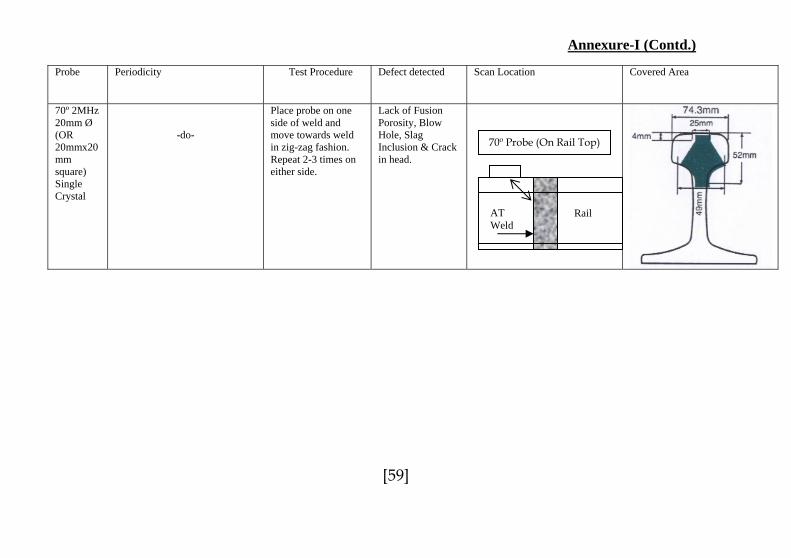
Annexure-I (Contd.)
Probe Periodicity Test Procedure Defect detected Scan Location Covered Area
70º 2MHz 20mm Ø (OR 20mmx20mm square) Single Crystal
-do-
Place probe on one side of weld and move towards weld in zig-zag fashion. Repeat 2-3 times on either side.
Lack of Fusion Porosity, Blow Hole, Slag Inclusion & Crack in head.
70º Probe (On Rail Top)
Rail AT Weld
[59]
Annexure-I (Contd.)
Probe Periodicity Test Procedure Defect detected Scan Location Covered Area
70º 2MHz 20mmx20mm square Single Crystal Hand Probe
-do-
Place probe at a distance 180mm from edge of the weld. Move probe towards weld in zigzag way on all 6 zones on either side of web. (12 moves)
Lack of Fusion Porosity, Blow Hole, Slag Inclusion in AT weld flange.
45º 2MHz 20mm Ø (OR 20mmx20mm square) Single Crystal
-do-
Place probe at a distance equal to the ht. of the rail. Move the probe 20mm on either side of this location. Repeat both sides with beam directing towards foot. (2 moves)
Half moon crack in bottom of weld foot.
45º Probe (On Rail Top)
70º Hand Probe on Rail Foot
[60]

Annexure-I (Contd.)
Probe Periodicity Test Procedure Defect detected Scan Location Covered Area
70º 2MHz 8mmx8mm square Single Crystal. (alternative to 45º probe)Hand Probe
-do-
Place probe at a distance 100mm from edge of the weld near the flange root. Move probe towards weld in zig zag way on all 4 sides at top and also bottom of weld flange on both sides of weld collar (6 moves).
Half moon crack in bottom of weld foot when hole is present in the web.
70º Miniature Probe on Web Foot Junction
Note fo lash Butt Welds: 45º and 70º, 2 MHz hand probing for web and flange: “In case f flash butt welds normally there is no need for hand testing (with 45º and 70º probes) howevehis opin
r F o
r; Chief Engineer may order hand probing with these probes in case failure rates are high in ion.”[61]
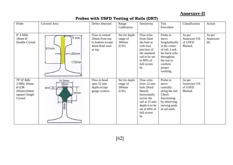
Annexure-II Probes with USFD Testing of Rails (DRT)
Probe Covered Area Defect detected Range Calibration
Sensitivity TestProcedure
Classification Action
0º 4 MHz 18mm Ø Double Crystal
Flaw in central 20mm from top to bottom except 4mm dead zone at top.
Set for depth range of 300mm (LW).
Flaw echo from 5mm dia hole at web-foot junction of the standard rail to be set to 60% of full screen ht.
Probe to move longitudinally at the center of rail. Look for back echo throughout the test to confirm proper working.
As per Annexure-VII of USFD Manual.
70º (F &B) 2 MHz 20mm Ø (OR 20mmx20mm square) Single Crystal
Flaw in head upto 52 mm depth except gauge corners.
Set for depth range of 300mm (LW).
Flaw echo from 12 mm hole (Need Based) horizontally across the rail at 25 mm depth is to be set at 60% of full screen ht.
Probe to move centrally along the rail. Check functioning by observing moving peak at rail ends.
As per Annexure-VII of USFD Manual.
As per Annexure-III.
[62]

Annexure-II (Contd.)
Probes with USFD Testing the Bolt-Holes (SRT) Probe Covered Area Defect detected Range
Calibration Sensitivity Test
Procedure Classification Action
0º 4MHz 18mm Ø Double Crystal
Flaw in central 20mm from top to bottom including horizontal star cracks in bolt-holes but, except 4mm dead zone at top.
Set for depth range of 300mm (LW).
Flaw echo from 5mm dia hole at web-foot junction of the standard rail to be set to 60% of full screen ht.
Probe to move longitudinally at the center of rail. Look for back echo throughout the test to confirm proper working.
As per Annexure-VII of USFD Manual.
70º 2MHz (F&B) 20mm Ø (OR 20mmx20mm square) Single Crystal
Flaw in head upto 52 mm depth except gauge corners.
Set for depth range of 300mm (LW).
Flaw echo from 12 mm hole (Need Based) horizontally across the rail at 25 mm depth is to be set at 60% of full screen ht.
Probe to move centrally along the rail. Check functioning by observing moving peak at rail ends.
As per Annexure-VII of USFD Manual.
As per Annexure-III
[63]

Annexure-II (Contd.)
Probes with USFD Testing the Bolt-Holes (SRT)
Probe Covered Area Defect detected Range Calibration
Sensitivity TestProcedure
Classification Action
37º 2 MHz (F&B) 20mmx20mm square Single Crystal.
Star cracks from bolt holes.
Set for depth range of 300mm (LW).
Flaw echo from 5mm long saw cut from bolt hole at 53º from vertical is to be set to 60% of the full screen ht.
To be moved on either side of the rail joint on the rail top table.
As per Annexure-VII of USFD Manual.
As per Annexure-III
[64]
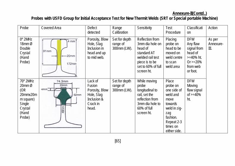
Annexure-II(Contd..) Probes with USFD Group for Initial Acceptance Test for New Thermit Welds (SRT or Special portable Machine)
Probe Covered Area Defect
detected Range Calibration
Sensitivity TestProcedure
Classification
Action
0º 2MHz 18mm Ø Double Crystal (Hand Probe)
Porosity, Blow Hole, Slag Inclusion in head and up to mid web.
Set for depth range of 300mm (LW).
Reflection from 3mm dia hole on head of standard AT welded rail test piece is to be set to 60% of full screen ht.
Placing probe on head to be moved on weld centre to scan weld area
DFW Any flaw signal from head of >=40% ht. Or >=20% from web or foot.
70º 2MHz 20mm Ø (OR 20mmx20mm square) Single Crystal (Hand Probe)
Lack of Fusion Porosity, Blow Hole, Slag Inclusion & Crack in head.
Set for depth range of 300mm (LW).
While moving probe longitudinal to rail, set the reflection from 3mm dia hole to 60% of full screen ht.
Place probe on one side of weld and move towards weld in zig-zag fashion. Repeat 2-3 times on either side.
DFW Moving flaw signal of >=40% ht.
As per Annexure-III.
[65]

Annexure-II(Contd..)
Probe Covered Area Defectdetected
Range Calibration
Sensitivity TestProcedure
Classification
Action
70º 2MHz 20mmx20mm square Single Crystal (Hand Probe)
Lack of Fusion Porosity, Blow Hole, Slag Inclusion in AT weld flange.
Set for depth range of 300mm (LW).
Move the probe towards 3mm dia hole in the middle of flange of AT weld and set the reflection to 60% of the full screen ht.
Place probe at a distance 180mm from edge of the weld. Move probe towards weld in zigzag way on all 6 locations on either. (12 moves)
DFW Any flaw signal of >=40% ht.
As per Annexure-III
[66]

Annexure-II (Contd…) Probes for Testing Thermit after Initial Acceptance Test (SRT or Special portable Machine)
Probe Covered Area Defectdetected
Range Calibration
Sensitivity TestProcedure
Classification
Action
0º 2MHz 18mm Ø Double Crystal (Hand Probe)
Porosity, Blow Hole, Slag Inclusion in head and up to mid web.
Set for depth range of 300mm (LW).
Reflection from 3mm dia hole on head of standard AT welded rail test piece is to be set to 60% of full screen ht.
Placing probe on head to be moved on weld centre to scan weld area
DFW Any flaw signal from head of >=40% ht. Or >=20% from web or foot.
70º 2MHz 20mm Ø (OR 20mmx20mm square) Single Crystal (Hand Probe)
Lack of Fusion Porosity, Blow Hole, Slag Inclusion & Crack in head.
Set for depth range of 300mm (LW).
While moving probe longitudinal to rail, set the reflection from 3mm dia hole to 60% of full screen ht.
Place probe on one side of weld and move towards weld in zig-zag fashion. Repeat 2-3 times on either side.
DFW Moving flaw signal of >=40% ht.
As per Annexure-III.
[67]
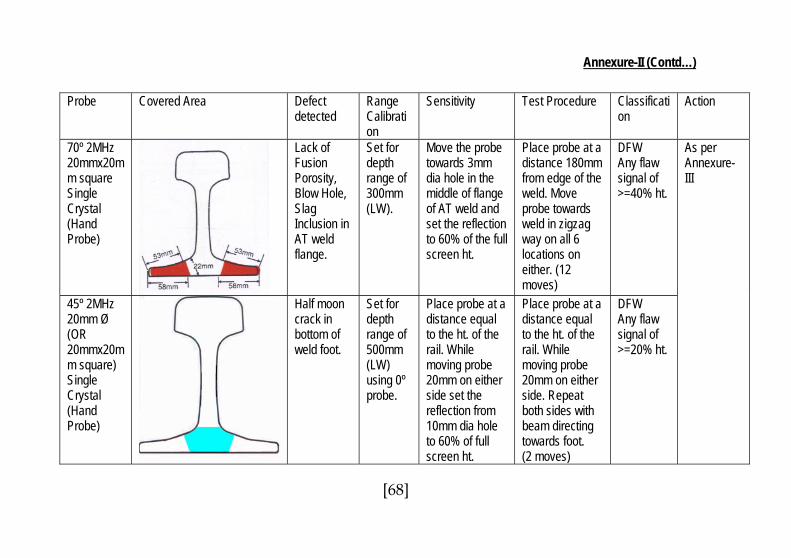
Annexure-II (Contd…)
Probe Covered Area Defectdetected
Range Calibration
Sensitivity Test Procedure Classification
Action
70º 2MHz 20mmx20mm square Single Crystal (Hand Probe)
Lack of Fusion Porosity, Blow Hole, Slag Inclusion in AT weld flange.
Set for depth range of 300mm (LW).
Move the probe towards 3mm dia hole in the middle of flange of AT weld and set the reflection to 60% of the full screen ht.
Place probe at a distance 180mm from edge of the weld. Move probe towards weld in zigzag way on all 6 locations on either. (12 moves)
DFW Any flaw signal of >=40% ht.
45º 2MHz 20mm Ø (OR 20mmx20mm square) Single Crystal (Hand Probe)
Half moon crack in bottom of weld foot.
Set for depth range of 500mm (LW) using 0º probe.
Place probe at a distance equal to the ht. of the rail. While moving probe 20mm on either side set the reflection from 10mm dia hole to 60% of full screen ht.
Place probe at a distance equal to the ht. of the rail. While moving probe 20mm on either side. Repeat both sides with beam directing towards foot. (2 moves)
DFW Any flaw signal of >=20% ht.
As per Annexure-III
[68]
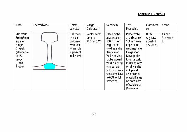
Annexure-II (Contd…)
Probe Covered Area Defectdetected
Range Calibration
Sensitivity TestProcedure
Classification
Action
70º 2MHz 8mmx8mm square Single Crystal. (alternative to 45º probe) (Hand Probe)
Half moon crack in bottom of weld foot when hole is present in the web.
Set for depth range of 300mm (LW).
Place probe at a distance 100mm from edge of the weld near the flange root. While moving probe towards weld in zigzag way set the reflection from simulated flaw to 60% of full screen ht.
Place probe at a distance 100mm from edge of the weld near the flange root. Move probe towards weld in zigzag way on all 4 sides at top and also bottom of weld flange on both sides of weld collar (6 moves)
DFW Any flaw signal of >=20% ht.
As per Annexure-III
[69]

Annexure-II
Area of Scan with all Probes combined (Shown in 60 Kg Rail Section)
Combined Scanned Area in Rail Combined Scanned Area in Thermit Weld
0˚ 2MHz
70˚
70˚Hand Probe For Gauge Face Detection
37˚
0˚ 4MHz
70˚
45˚
45˚/70˚ Hand Probe
[70]
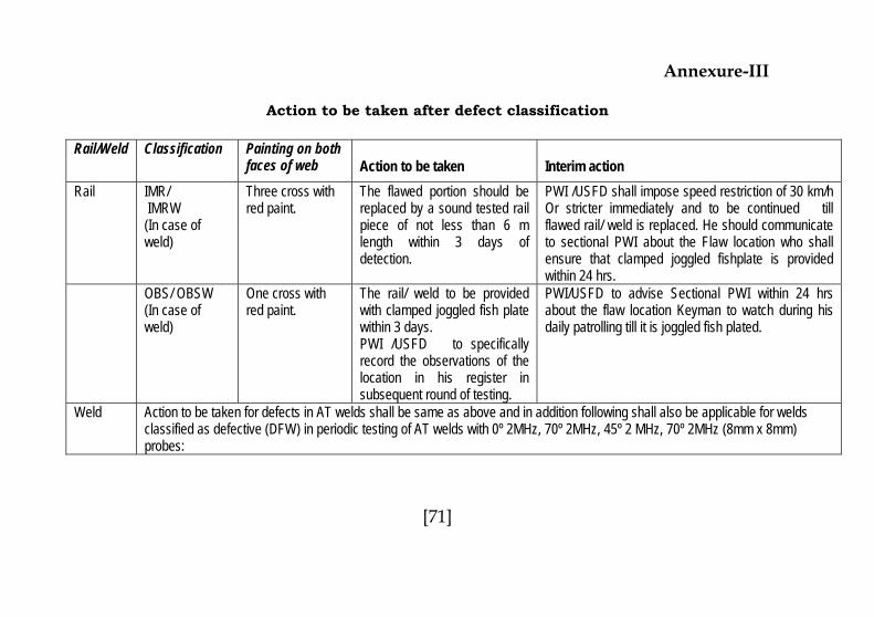
Annexure-III
Action to be taken after defect classification
Rail/Weld Classification Painting on both
faces of web Action to be taken Interim action Rail IMR/
IMRW (In case of weld)
Three cross with red paint.
The flawed portion should be replaced by a sound tested rail piece of not less than 6 m length within 3 days of detection.
PWI /USFD shall impose speed restriction of 30 km/h Or stricter immediately and to be continued till flawed rail/ weld is replaced. He should communicate to sectional PWI about the Flaw location who shall ensure that clamped joggled fishplate is provided within 24 hrs.
OBS/ OBSW (In case of weld)
One cross with red paint.
The rail/ weld to be provided with clamped joggled fish plate within 3 days. PWI /USFD to specifically record the observations of the location in his register in subsequent round of testing.
PWI/USFD to advise Sectional PWI within 24 hrs about the flaw location Keyman to watch during his daily patrolling till it is joggled fish plated.
Weld Action to be taken for defects in AT welds shall be same as above and in addition following shall also be applicable for welds classified as defective (DFW) in periodic testing of AT welds with 0º 2MHz, 70º 2MHz, 45º 2 MHz, 70º 2MHz (8mm x 8mm) probes:
[71]
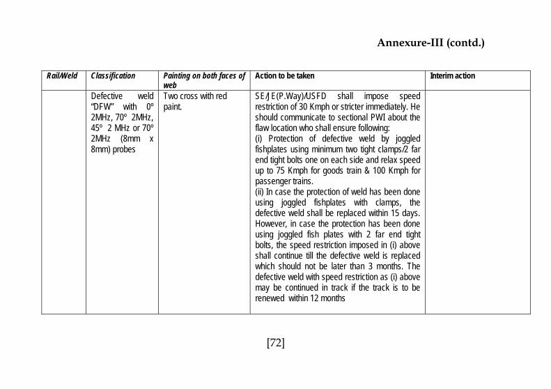
Annexure-III (contd.)
Rail/Weld Classification Painting on both faces of web
Action to be taken Interim action
Defective weld “DFW” with 0º 2MHz, 70º 2MHz, 45º 2 MHz or 70º 2MHz (8mm x 8mm) probes
Two cross with red paint.
SE/JE(P.Way)/USFD shall impose speed restriction of 30 Kmph or stricter immediately. He should communicate to sectional PWI about the flaw location who shall ensure following: (i) Protection of defective weld by joggled fishplates using minimum two tight clamps/2 far end tight bolts one on each side and relax speed up to 75 Kmph for goods train & 100 Kmph for passenger trains. (ii) In case the protection of weld has been done using joggled fishplates with clamps, the defective weld shall be replaced within 15 days. However, in case the protection has been done using joggled fish plates with 2 far end tight bolts, the speed restriction imposed in (i) above shall continue till the defective weld is replaced which should not be later than 3 months. The defective weld with speed restriction as (i) above may be continued in track if the track is to be renewed within 12 months
[72]

NOTES
[73]

NOTES
[74]

NOTES
[75]
Top Related