


Languages
Pages
Legal

0
ANPR Camera Installation Manual
UD03906N

Automatic Number Plate Recognition Camera·Installation Manual
1
1 ANPR Camera Installation Manual
About this Manual
This Manual is applicable to ANPR Network Camera.
This manual may contain several technical or printing errors, and the
content is subject to change without notice. The updates will be
added to the new version of this manual. We will readily improve or
update the products or procedures described in the manual.
Different models may differ in functions, please refer to the actual
GUI of each model.
DISCLAIMER STATEMENT
“Underwriters Laboratories Inc. (“UL”) has not tested the
performance or reliability of the security or signaling aspects of this
product. UL has only tested for fire, shock or casualty hazards as
outlined in UL’s Standard(s) for Safety, UL60950-1. UL Certification
does not cover the performance or reliability of the security or
signaling aspects of this product. UL MAKES NO REPRESENTATIONS,
WARRANTIES OR CERTIFICATIONS WHATSOEVER REGARDING THE
PERFORMANCE OR RELIABILITY OF ANY SECURITY OR SIGNALING
RELATED FUNCTIONS OF THIS PRODUCT.”

Automatic Number Plate Recognition Camera·Installation Manual
2
2 Safety Instruction
These instructions are intended to ensure that user can use the
product correctly to avoid danger or property loss.
The precaution measure is divided into “Warnings” and “Cautions”
Warnings: Serious injury or death may occur if any of the warnings
are neglected. Cautions: Injury or equipment damage may occur if any of the
cautions are neglected.
Warnings
Proper configuration of all passwords and other security
settings is the responsibility of the installer and/or end-user.
In the use of the product, you must be in strict compliance with
the electrical safety regulations of the nation and region. Please
refer to technical specifications for detailed information.
Input voltage should meet both the SELV (Safety Extra Low
Voltage) and the Limited Power Source with 24 VAC or 12 VDC
Warnings Follow these
safeguards to prevent
serious injury or death.
Cautions Follow these precautions
to prevent potential injury or
material damage.

Automatic Number Plate Recognition Camera·Installation Manual
3
3 according to the IEC60950-1 standard. Please refer to technical
specifications for detailed information.
Do not connect several devices to one power adapter as
adapter overload may cause over-heating or a fire hazard.
Please make sure that the plug is firmly connected to the power
socket. When the product is mounted on wall or ceiling, the
device shall be firmly fixed.
If smoke, odor or noise rise from the device, turn off the power
at once and unplug the power cable, and then please contact
the service center.
Cautions
Make sure the power supply voltage is correct before using the
camera.
Do not drop the camera or subject it to physical shock.
Do not touch sensor modules with fingers. If cleaning is
necessary, use clean cloth with a bit of ethanol and wipe it
gently. If the camera will not be used for an extended period,
please replace the lens cap to protect the sensor from dirt.
Do not aim the camera at the sun or extra bright places.
Blooming or smearing may occur otherwise (which is not a
malfunction), and affect the endurance of sensor at the same
time.
The sensor may be burned out by a laser beam, so when any
laser equipment is in using, make sure that the surface of
sensor will not be exposed to the laser beam.

Automatic Number Plate Recognition Camera·Installation Manual
4
4 To avoid heat accumulation, good ventilation is required for
operating environment.
Keep the camera away from liquid while in use.
While in delivery, the camera shall be packed in its original
packing, or packing of the same texture.
Regular part replacement: a few parts (e.g. electrolytic
capacitor) of the equipment shall be replaced regularly
according to their average enduring time. The average time
varies because of differences between operating environment
and using history, so regular checking is recommended for all
the users. Please contact with your dealer for more details.
Improper use or replacement of the battery may result in
hazard of explosion. Replace with the same or equivalent type
only. Dispose of used batteries according to the instructions
provided by the battery manufacturer.
If the product does not work properly, please contact your
dealer or the nearest service center. Never attempt to
disassemble the camera yourself. (We shall not assume any
responsibility for problems caused by unauthorized repair or
maintenance.)
Automatic Number Plate Recognition Camera·Installation Manual
5
5
Table of Contents 1 Introduction .................................................................................... 6
1.1 ANPR Camera Overview .................................................. 6 1.2 Typical Application Scene ................................................ 6
1.2.1 Entrance Surveillance ........................................... 6 1.2.2 Road Traffic Surveillance....................................... 7
2 Installation ...................................................................................... 8 2.1 Before you Start .............................................................. 8 2.2 Lens Selection ................................................................. 8 2.3 Installation Angle .......................................................... 10 2.4 Entrance Surveillance Application ................................. 10 2.5 Road Traffic Surveillance Application ............................. 11
3 License Plate Recognition ............................................................. 14 3.1 Depth of Field ............................................................... 15 3.2 License Plate Recognition .............................................. 16 3.3 Pixel Requirement ......................................................... 28
0504011061208

Automatic Number Plate Recognition Camera·Installation Manual
6
6
1 Introduction
1.1 ANPR Camera Overview
Automatic Number Plate Recognition (ANPR) cameras detect passing
vehicles and captures the license plates. To obtain the maximum
license plate recognition accuracy, you need to install the ANPR
camera in a proper way to get the clear image.
1.2 Typical Application Scene
1.2.1 Entrance Surveillance
To recognize license plate of the entrance, you are recommended to
install the camera on both sides of the barrier gate.
Figure 1-1 Entrance Surveillance Scene

Automatic Number Plate Recognition Camera·Installation Manual
7
7 1.2.2 Road Traffic Surveillance
To recognize two lanes, you are recommended to install the camera
in the middle of a cross pole, and the vehicle speed should be lower
than 60km/h.
If the speed is higher than 60km/h, the camera is recommended to
recognize only one lane.
Figure 1-2 Road Traffic Surveillance Scene
Automatic Number Plate Recognition Camera·Installation Manual
8
8
2 Installation
2.1 Before you Start
The camera installation condition should meet the following
requirements:
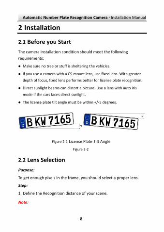
Make sure no tree or stuff is sheltering the vehicles.
If you use a camera with a CS-mount lens, use fixed lens. With greater
depth of focus, fixed lens performs better for license plate recognition.
Direct sunlight beams can distort a picture. Use a lens with auto iris
mode if the cars faces direct sunlight.
The license plate tilt angle must be within +/-5 degrees.
Figure 2-1 License Plate Tilt Angle
Figure 2-2
2.2 Lens Selection
Purpose:
To get enough pixels in the frame, you should select a proper lens.
Step:
1. Define the Recognition distance of your scene.
Note:
Automatic Number Plate Recognition Camera·Installation Manual
9
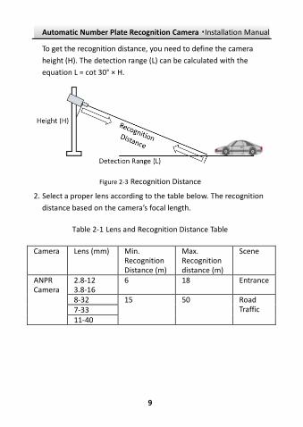
9 To get the recognition distance, you need to define the camera
height (H). The detection range (L) can be calculated with the
equation L = cot 30° × H.
Figure 2-3 Recognition Distance
2. Select a proper lens according to the table below. The recognition
distance based on the camera’s focal length.
Table 2-1 Lens and Recognition Distance Table
Camera Lens (mm) Min. Recognition Distance (m)
Max. Recognition distance (m)
Scene
ANPR Camera
2.8-12 3.8-16
6 18 Entrance
8-32 15 50 Road Traffic 7-33
11-40
Automatic Number Plate Recognition Camera·Installation Manual
10
10
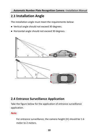
2.3 Installation Angle
The installation angle must meet the requirements below:
Vertical angle should not exceed 30 degrees.
Horizontal angle should not exceed 30 degrees.
2.4 Entrance Surveillance Application
Take the figure below for the application of entrance surveillance
application.
Note:
For entrance surveillance, the camera height (H) should be 1.6
meter to 2 meters.

Automatic Number Plate Recognition Camera·Installation Manual
11
11
L > 6m
L > 6m
Figure 2-4 Entrance Surveillance Application
2.5 Road Traffic Surveillance Application
Notes:
For road traffic surveillance, the camera height should be
between 5 meters and 6 meters.
To recognize two or more lanes, you are recommended to
mount a camera on a crossbar.
Make sure the pole for mounting the camera does not vibrate a
lot when heavy truck or similar vehicle passes.

Automatic Number Plate Recognition Camera·Installation Manual
12
12 Take the figure below for the application of two lane with camera
mounted on the side of crossbar.
6 m > H > 5 m
25 m > L > 20 m
Field of View Edge
Figure 2-5 Two Lanes (Camera on the Side of Crossbar)
Take the figure below for the application of two lane with camera
mounted in the middle of crossbar.

Automatic Number Plate Recognition Camera·Installation Manual
13
13
6 m > H > 5 m
20 m > L > 15 m
Field of View Edge
Figure 2-6 Two Lanes (Camera in the Middle of Crossbar)

Automatic Number Plate Recognition Camera·Installation Manual
14
14
3 License Plate Recognition
Before you start:
When you use the license plate recognition function, please meet
the requirements below:
To reduce the effect of the car’s headlights at night, the shutter speed
should be no less than 1/1000 s. To NOT obscure the edge of the lines
(especially shadows), the shutter speed should not exceed 4/1000 s.
To avoid overexposure of license plate, the recommended value of Gain
setting is 20.
Turn off the WDR and BLC functions to keep all the details.
Keep the Digital Noise Reduction value between 10 and 20.
Sometimes, invalid information may be detected as license plate such
as: ads or image parts with numbers and letters. You should follow the
steps below:
a) Adjust the ROI accordingly to avoid the parts that may be false detected.
b) Adjust the min and max license plate pixel settings.
c) Sometimes, change the angle of lens or move the camera.
Set the exposure time according to the table below. We assume the
camera is mounted at a horizontal angle of 30 degrees.
Exposure Time (s) Maximum Vehicle Speed (kmph)
1/100 5
1/500 40
1/1000 100
1/2000 200
1/4000 400
Automatic Number Plate Recognition Camera·Installation Manual
15
15
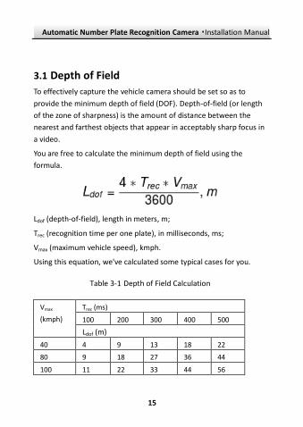
3.1 Depth of Field
To effectively capture the vehicle camera should be set so as to
provide the minimum depth of field (DOF). Depth-of-field (or length
of the zone of sharpness) is the amount of distance between the
nearest and farthest objects that appear in acceptably sharp focus in
a video.
You are free to calculate the minimum depth of field using the
formula.
Ldof (depth-of-field), length in meters, m;
Trec (recognition time per one plate), in milliseconds, ms;
Vmax (maximum vehicle speed), kmph.
Using this equation, we've calculated some typical cases for you.
Table 3-1 Depth of Field Calculation
Vmax
(kmph)
Trec (ms)
100 200 300 400 500
Ldof (m)
40 4 9 13 18 22
80 9 18 27 36 44
100 11 22 33 44 56

Automatic Number Plate Recognition Camera·Installation Manual
16
16
120 13 27 40 53 67
140 16 31 47 62 78
180 20 40 60 80 100
200 22 44 67 89 111
220 24 49 73 98 122
240 27 53 80 107 133
Notes:
The minimum sizes of the number plate on the edges of the zone
of sharpness shall not be less than the width pixel requirements in
Section 3.2.
DOF depends on F-number of lens diaphragm, which may be
automatically adjusted by a camera in case of illumination
changes. So iris control must be set to "manual", not "auto". Or
ensure that DOF length is enough for the worst possible
illumination case.
Change the iris type to manual before focus the lens, and change
the iris type back to auto-iris.
3.2 License Plate Recognition
Purpose:
By using the client software and web browser, you can set the rule of
capture pictures and make the ANPR camera identify the numbers.
Here we take the road traffic surveillance application as an example.
Step:

Automatic Number Plate Recognition Camera·Installation Manual
17
17 1. Enable Vehicle Detection.
1). Open web browser.
2). Access to the camera via web browser.
3). Go to Configuration-> Advanced Configuration-> System ->
VCA Resource and select Vehicle Detection.
4). Go to Advanced Configuration->Road Traffic>Detection
Configuration tab.
5). Select Vehicle Detection and check the checkbox.
Figure 3-1 Enable Vehicle Detection
2. Set the detection area.
1). Select the corresponding region.

Automatic Number Plate Recognition Camera·Installation Manual
18
18
Figure 3-2 Select Region and Lane Number
2). Click and drag the lane line to set the range, and drag the line
to adjust the length and angle.
3). Set the maximum and minimum size of the license plate.
Figure 3-3 License Plate Region Settings
Notes:
For detailed information about license plate recognition,
refer to the User Manual of LPR Network Camera.

Automatic Number Plate Recognition Camera·Installation Manual
19
19 The operation and configuration for road traffic application
varies according to different regions. For EU and CIS region,
refer to Section 3.2.1; for other regions, refer to Section
3.2.2.
3. (Optional) Enable the LED light supplement.
1). Enter Configuration -> Advanced Configuration -> System ->
External Device.
2). Check the checkbox of Enable Supplement Light.
3). Click Save to save the settings.
Figure 3-4 Enable LED Light
Note:
To recognize license plate at night, use a camera with IR LED and
enable the LED light supplement.
To connect and trigger the radar, please refer to the appendix.

Automatic Number Plate Recognition Camera·Installation Manual
20
20 3.2.1 EU and CIS Region License Plate Recognition Settings
Steps:
1. Select the lane number from the dropdown list. Up to 4 lanes are
selectable.
2. Select the region according to your location. Europe region, CIS
region, and Europe & CIS region are selectable.
3. Drag the lane line to set its position, or drag one end of the lane
line to adjust the length and position. After you set the lane line
and save the settings, a detection area will appear in the live view
window.
Note: Only one license plate can be captured at one time for
each lane.
4. Configure the license plate settings.
1). Set the min. width and max. width of the license plate by input
the value manually. The min. width and the max. width range
from 130 to 1920.
2). Select the upload mode in the Select Mode dropdown list
according to the actual application scene.
The license plate picture will be uploaded if the vehicle exits the
detection area within the time interval.
Entrance/Exit: The license plate picture will be uploaded
immediately when vehicle detected.
City Street: The license plate picture will be uploaded 5
seconds after vehicle detected.
Custom: You can modify the Time Interval in the text field.

Automatic Number Plate Recognition Camera·Installation Manual
21
21 Alarm Input: The license plate picture will be recognized and
uploaded when the device receive alarm input.
Notes:
When Alarm Input is selected, the alarm input "A<-1" will
automatically be assigned to trigger vehicle detection and its
alarm type is always NO.
When Alarm Input is selected and saved, formerly configured
linkage method for "A<-1" will be canceled.
Figure 3-5 Vehicle Detection Configuration
5. Set the Arming Schedule for Vehicle Detection.

Automatic Number Plate Recognition Camera·Installation Manual
22
22 1). To edit the arming schedule, click Edit.
2). Choose the day you want to set the arming schedule.
3). Click to set the time period for the arming schedule.
4). (Optional) After you set the arming schedule, you can click
Copy to copy the schedule to other days.
5). Click OK to save the settings.
Note: The time of each period cannot be overlapped.
6. Check the checkbox to select the linkage method. Notify
surveillance center and upload to FTP are selectable.
Notify Surveillance Center: Send an exception or alarm signal
to remote management software when an event occurs.
Upload to FTP: Capture the image when an alarm is triggered
and upload the picture to a FTP server. And save the picture
on the local memory card or connected NAS.
Trigger Alarm Output: Trigger one or more external alarm
outputs when an event occurs.
Note: To trigger an alarm output when an event occurs, refer
to Section 5.6.4 Configuring Alarm Output to set the related
parameters.
7. Click Save to save the settings.
3.2.2 Universal Region License Plate Recognition Settings
Steps:
1. Select the detection type as Vehicle Detection.

Automatic Number Plate Recognition Camera·Installation Manual
23
23 2. Check the checkbox of Enable the enable road traffic.
3. Select the lane number from the drop-down list. Up to 4 lanes are
selectable.
4. Select the region according to your location. Europe region and
Russian region are selectable.
5. Click and drag the lane line to set its position, or click and drag
one end of the lane line to adjust the length and position. After
you set the lane line and save the settings, a detection area will
appear in the live view window.
Note: Only one license plate can be captured at one time for
each lane.
6. Configure the license plate settings.
1). Set the min. width and max. width of the license plate by input
the value manually. The min. width and the max. width range
from 130 to 1920.
2). Check the checkbox to enable the Real-Time LPR Result. You
can see the live view of the passing vehicles, and check the
captured license plates. The Real-Time LPR Result page does
not display if you leave the checkbox unchecked.
7. Set the Arming Schedule for Vehicle Detection.
1). To edit the arming schedule, click Edit button.
2). Choose the day you want to set the arming schedule.
3). Click to set the time period for the arming schedule.
4). (Optional) After you set the arming schedule, you can click the
Copy button to copy the schedule to other days.
5). Click OK to save the settings.

Automatic Number Plate Recognition Camera·Installation Manual
24
24
Note: The time of each period cannot be overlapped.
8. Check the checkbox to select the linkage method. Notify
surveillance center and upload to FTP are selectable.
Notify Surveillance Center: Send an exception or alarm signal
to remote management software when an event occurs.
Upload to FTP: Capture the image when an alarm is triggered
and upload the picture to a FTP server. And save the picture
on the local SD card or connected NAS.
9. Click Save to save the settings.
Figure 3-6 Vehicle Detection Configuration

Automatic Number Plate Recognition Camera·Installation Manual
25
25
3.3 Real-time LPR Result
3.3.1 EU and CIS Region Real-time LPR Result
The real-time LPR result page displays the captured license plate in
the license plate result area. The information including capture time,
plate No., captured picture, country, lane and direction will be listed
as well.
Enter the Real-time LPR Result interface:
Configuration > Advanced Configuration > Road Traffic > Real-time
LPR Result
Figure 3-7 Real-time LPR Result Interface

Automatic Number Plate Recognition Camera·Installation Manual
26
26
Notes:
You can export vehicle information in the form of an excel file in
playback interface. Refer to User Manual of Network Camera_LPR
for details.
The real-time LPR result page appears only when you check the
Enable Real-time LPR Result checkbox in Real-time LPR Result
page.
For the item of country, you can uncheck the checkbox to hide it.
Figure 3-8 Checkbox
3.3.2 Universal Regions Real-time LPR Result
The real-time LPR result page displays the captured license plate in
the license plate result area. The information including capture time,
plate No., license plate number, and country will be listed as well.

Automatic Number Plate Recognition Camera·Installation Manual
27
27
Figure 3-9 Real-time LPR Result Interface
Notes:
The real-time LPR result page appears only when you check the
checkbox of Enable Real-time LPR Result in detection
configuration page.
Up to 20 latest pictures can be displayed on the LPR result area.

Automatic Number Plate Recognition Camera·Installation Manual
28
28
3.4 Pixel Requirement
Purpose:
The dimensions of the license plate vary according to different areas.
To get a valid image of ANPR camera, you need to measure the plate
size and define the minimum valid pixel of the live view.
Steps:
1. Capture a live view picture of passing vehicle.
2. Measure the pixel of the license plate.
4). Open Paint.
Note: You can use any graphic editors (like photoshop) to
measure the pixels of the license plate.
Figure 3-10 License Plate Pixels

Automatic Number Plate Recognition Camera·Installation Manual
29
29 5). Click and select the license plate. In the lower left
corner of the paint interface, the pixel of the frame displays.
Notes:
License plate itself must be clear in the video.
The plate should be between 16 to 50 pixels of height, and for
better recognition result, the plate should be between 20 to 40
pixels in height.
The plate should be between 100 to 200 pixels of width, and for
better recognition result, in some regions the plate should be
between 100 to 180 pixels in width.
Automatic Number Plate Recognition Camera·Installation Manual
30
30
Appendix
Radar Trigger
Purpose:
If you need to enable a radar trigger, follow the steps below.
Before you start:
Prepare an RS-485 serial wire.
Steps:
1. Install the radar in the middle of the lane. For details, refer to the
manual of radar.
Note: Install the radar about 0.5 m from the camera spot.
2. Install the driver of the serial wire in your PC.
3. Connect the terminal 485+, 485-, and GND of the RS-485 wire to
the radar, and connect the USB terminal to the PC.
4. Power on the radar.
5. Run the radar demo.
1). Select COM and press the Enter the Setup button.

Automatic Number Plate Recognition Camera·Installation Manual
31
31
Figure 3-11 Radar Server Configuration
2). Check the Head Trigger checkbox and click Work Mode button.
3). Check the Single Byte checkbox and click Data Format button.
4). Enter the mounting height (6) and click Mounting height
button.
5). Enter the trigger distance (19) and click Trigger distance
button.
6). Click Save the current Radar Configuration button.
7). Click Exit the Setup.

Automatic Number Plate Recognition Camera·Installation Manual
32
32
Figure 3-12 Run the Radar
8). Click Enter the Setup button.
9). Check the Continue Trigger checkbox and click Work Mode
button.
10). Click Exit the Setup button.
11). Enter FA 38 68 30 FB in the textbox, and click Send Command.
12). Click ASCII display forced to switch button.
Note: Calculate the trigger point by the equation
(29.8+12.8)/2.
13). Repeat the steps (8) to (10).
6. Link the radar to the camera.
Note: The radar linkage interface varies according to different
models, the steps below are only for reference.

Automatic Number Plate Recognition Camera·Installation Manual
33
33
Figure 3-13 Radar Linkage
1). In the interface of the ANPR camera, go to Configuration ->
Application Mode.
2). Select the application mode as RS-485 Radar.
3). Select the total lanes, radar type and the linkage RS-485 No.
4). Click Draw LPR Area to draw the area.
5). Click Save button.
7. Edit the serial port No.
1). Go to Configuration -> Device Configuration -> System
Configuration -> Serial Ports.
2). Edit the Baudrate of RS-485 parameters to 9600.

Automatic Number Plate Recognition Camera·Installation Manual
34
34 8. (Optional) Set the text overlay.
1). Go to Configuration -> Device Configuration -> Text Overlay ->
Single Picture Overlay.
2). Check the checkbox of where you want to see the overlay on
the picture.
3). Select the overlay information from the list
4). Click Save.
5). In the Composed Picture Overlay interface and Video interface,
repeat the steps (2) to (4).

0
Top Related