


Languages
Pages
Legal

Analysis of cylinder liners lubrication systems in modern slow speed marine
engines
Treball Final de Grau
Facultat de Nàutica de Barcelona Universitat Politècnica de Catalunya
Treball realitzat per:
Luis Hernández Espínola
Dirigit per:
Włodzimierz Kamiński Manuel Rodríguez Castillo
Grau en Tecnologies Marines
Barcelona, 4 de juliol de 2018
Departament de Ciència i Enginyeria Nàutiques


TABLE OF CONTENTS
Lubrication ................................................................................................................... 3
Actuator activation ....................................................................................................... 5
Cooling system ............................................................................................................. 5
Cleaning ....................................................................................................................... 5
Sealing .......................................................................................................................... 6
Preventing corrosion .................................................................................................... 6
Minerals ........................................................................................................................ 7
Synthetic ....................................................................................................................... 7
Semi-synthetics ............................................................................................................ 8
Oil Additives and characteristics ................................................................................. 9
Density .................................................................................................................. 9
Viscosity ............................................................................................................. 10
Flash point ........................................................................................................... 11
Fire point ............................................................................................................. 11
Freezing point ..................................................................................................... 11
Acidity ................................................................................................................ 11
Alkaline-TBN capacity (by additives) ................................................................ 11
Capacity against oxidation and nitration (by additives) ..................................... 12
Detergent and dispersant capacity (by additives) ............................................... 12
Anti-foam capacity .......................................................................................... 12
Lubricant oils classification: ...................................................................................... 13
Viscosity classification ....................................................................................... 13
Classification by service ..................................................................................... 14
Cylinder oil and System oil ........................................................................................ 15
Cylinder oil ......................................................................................................... 15
System oil ........................................................................................................... 16
Talusia HR 70 ............................................................................................................ 17
Talusia Universal ....................................................................................................... 18
Four-stroke engines .................................................................................................... 20
Two-stroke crosshead engines (CLU3) ...................................................................... 20
Lubricating Accumulator .................................................................................... 21
Lubricating Quills ............................................................................................... 22
Lubrication principle .......................................................................................... 22
CLU3 and CLU4 lubricating systems ........................................................................ 23
Oil feed rates, wear and economics of cylinder lubrications ..................................... 24
Oil feed rates ....................................................................................................... 24
Slow-steaming .................................................................................................... 25
Excess cylinder oil fouling and gumming .......................................................... 25
Excessive liner wear: .......................................................................................... 26
Cold corrosion .................................................................................................... 26
Cost saving.......................................................................................................... 27
Alpha Adaptive Cylinder Oil Control (Alpha ACC) ................................................. 28
Main Components ...................................................................................................... 28
Pump Station and Starter Panels ......................................................................... 28
Lubrication Units ................................................................................................ 28
Alpha Lubricator Control Unit (ALCU) ............................................................. 29
Load transmitter .................................................................................................. 29
Trigger system (Shaft encoder) .......................................................................... 30
6.2.6 Backup trigger system ............................................................................... 30
Human Machine Interface (HMI) panel ............................................................. 30
Working Principle ...................................................................................................... 31
Main Components ...................................................................................................... 33
Pulse Lubricating Module................................................................................... 33
Lubricator ........................................................................................................... 33
Servo Oil Supply (RTA engines) ........................................................................ 34
Pressure reducing unit (RT-flex engines) ........................................................... 34
Crank angle sensors ............................................................................................ 34
Working Principle ...................................................................................................... 35
Control and Monitoring System ................................................................................. 36
Comparison between mentioned systems .................................................................. 36
Disadvantages of Accumulator and Quill Systems (CLU3) ............................... 36
Advantages of Alpha Lubricator System ............................................................ 36
Advantages of Pulse Lubricating System ........................................................... 36
Purpose of lubricant oils analysis............................................................................... 37

Lubricant oil analysis ................................................................................................. 38
Fluid Properties ................................................................................................... 38
Contamination ..................................................................................................... 38
Wear Debris ........................................................................................................ 38
Oil Analysis Tests ...................................................................................................... 38
Wear Debris Analysis ......................................................................................... 39
Viscosity ............................................................................................................. 39
Capillary Tube Viscometer Test Method ............................................................ 39
Rotary Viscometer Test Method ......................................................................... 40
Acid Number/Base Number ................................................................................ 40
Fourier transform infrared (FTIR) ...................................................................... 40
Elemental Analysis ............................................................................................. 41
Particle Counting ................................................................................................ 42
Analytical Microscopy ........................................................................................ 43
Moisture Analysis ........................................................................................... 44
Soot analysis .................................................................................................... 44
Oxidation analysis ........................................................................................... 45
Sulfation analysis ............................................................................................ 46
Nitration .......................................................................................................... 46
Acid Number (AN) ......................................................................................... 46
Base Number (BN) .......................................................................................... 47
AN and BN Units of Measurement ................................................................. 47
Gas Chromatography Test for Fuel Dilution .................................................. 48
Cylinder Drain Oil analysis ........................................................................................ 49
Sampling .................................................................................................................... 49
Procedure ............................................................................................................ 51
Websites ................................................................................................................. 55
Books and publications ........................................................................................... 56


1
Introduction
The use of lubricants dates back to earlier times that people might think. Over the history there
have been many lubricants made from different materials, and always replaced by better ones.
For example, animal fats such as tallow were used as lubricants on primitive machinery like the
wooden wheel. After that around 1400 B.C. the Egyptians mixed animal fat with calcium soap
obtaining a grease used to lubricate their chariot wheels.
This has been going on and on until the lubricants used nowadays, which are made from crude
petroleum.
The reason for using lubricants in the moving parts is reducing the friction between the surfaces,
in order to prevent the loss of power generated within the engine cylinders.
Doing that will not only increase the life of the components but also will increase the engine
efficiency, which would directly mean a cost reduction.
Piston rings play a very important role in the performance and endurance of the engine. Its
function is to provide an optimum sealing, lowering wear and friction at the same time. The
lube oil consumption and blow-by in an engine is directly related to the sealing function of the
piston rings. Beside that the stricter emission laws have increased even more the need of
reducing the lube oil consumption, which has a very high impact on the emissions of particles.
The piston-ring-liner system is the major source of lube oil consumption. For that reason it
needs to be designed to minimize the cylinder bore distortion and lube oil consumption by
increasing the piston ring stability and conformability, optimizing the liner surface finish, etc.
Cylinder lubrication conditions have changed considerably over the past 20 years. There has
been continuous development of the diesel engine since its inception, particularly in respect of
the power output from each cylinder unit. The increase in power output has an effect on engine
lubrication conditions. The combination of increasing power output and deteriorating fuel
quality has had a major influence on cylinder lubrication conditions in modern 2-stroke diesel
engines.
In 1982 the typical cylinder lubricant feed rate for a uni-flow scavenge engine was 0.67g/kWh
(0.5g/bhp·hour), which indicates that the lubricant consumption of such a 10 cylinder 900mm
bore engine would be 562kg per day. With a 42% increase in power, and typical lubricant feed
rates having increased from 0.67g/kWh to 1.34g/kWh (0.5g to 1.0g/bhp.hour) and more, the
lubricant consumption for the current model will be about 1,600kg of cylinder lubricant per
day.

2
A high level in oil consumption may be caused by one of the following reasons:
Poor quality oil
Increased wear of piston assemblies
Loss of oil rings mobility
Valve stem seals don’t work
Defective crankcase ventilation
Oil leaks
Oil release into the exhaust pipe through the turbine
Oil release in the cooling system
These situations or a combination of them might lead to various consequences such as:
Increased oil waste (burn)
High carbon formation
Significant contamination of the engine
Increased wear of friction parts
Decrease of the compression and quality of fuel combustion
Reduced oil life
Loss of elasticity of oil seals
Failure of the engine
As we can see, these consequences affect to the entire engine and can cause important failures
or even the breakdown of the engine itself.
Fig.1 Dirty engine due to poor quality lube oil Fig.2 Worn piston
3
Functions and role of cylinder lubricating oil in engine
Lubrication
There are two types of lube oil systems to distinguish. One in which the oil is stored in the sump
(mainly for 4-stroke engines) and the other in which it is stored in a drain tank (2-stroke engines)
which are the ones taken in account in this project.
The stages of the lube oil system can be summarized as follows:
The oil from the drain tank is drawn by a lube oil pump through a strainer which prevents
damaging the pump by external particles
Discharged oil passes into a cooler for heat exchange to take place (lowering the lube
oil temperature to operational levels)
Oil flows into a manifold, which distributes oil to the engine bearings, gearings and
piston.
Oil runs into a crankcase and a strainer before settling in the drain tank again
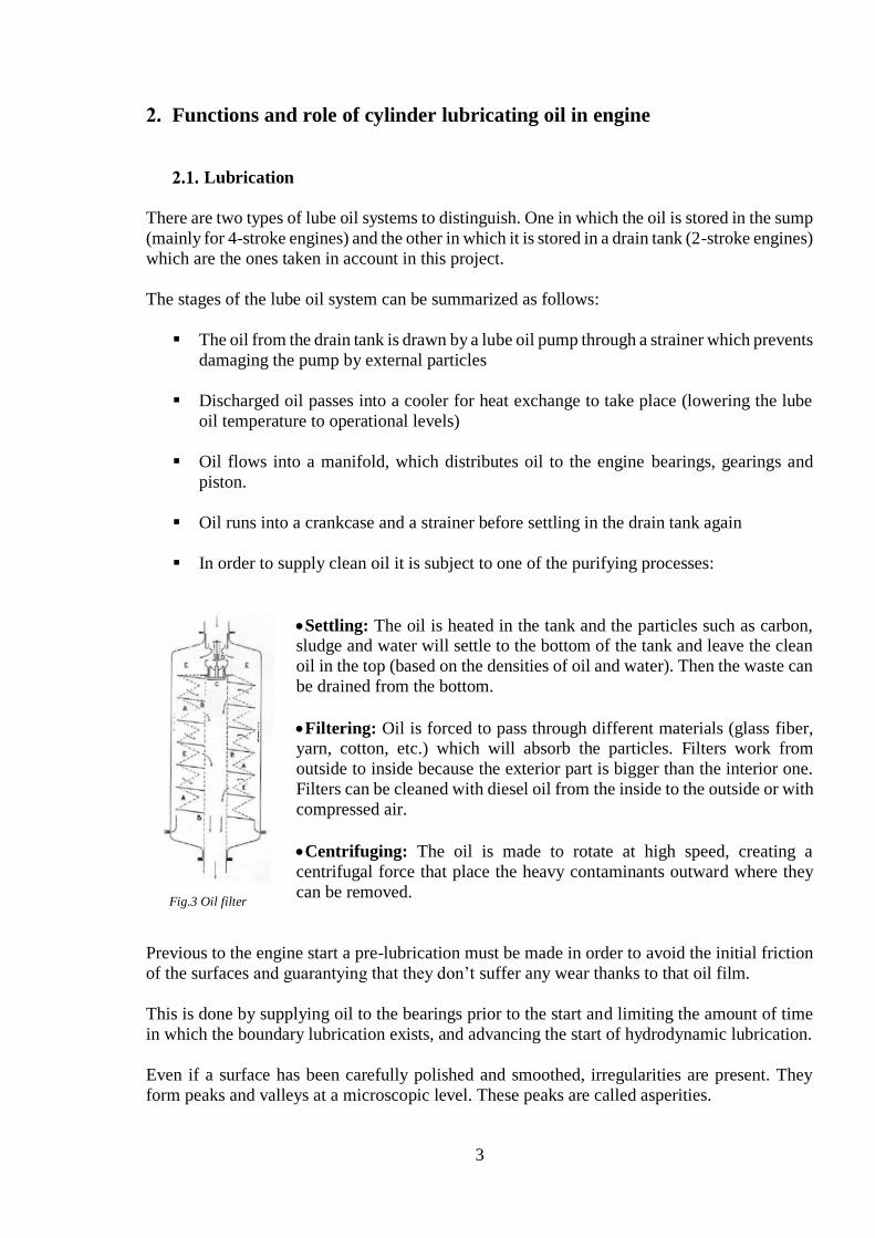
In order to supply clean oil it is subject to one of the purifying processes:
Settling: The oil is heated in the tank and the particles such as carbon, sludge and water will settle to the bottom of the tank and leave the clean
oil in the top (based on the densities of oil and water). Then the waste can
be drained from the bottom.
Filtering: Oil is forced to pass through different materials (glass fiber, yarn, cotton, etc.) which will absorb the particles. Filters work from
outside to inside because the exterior part is bigger than the interior one.
Filters can be cleaned with diesel oil from the inside to the outside or with
compressed air.
Centrifuging: The oil is made to rotate at high speed, creating a
centrifugal force that place the heavy contaminants outward where they
can be removed.
Previous to the engine start a pre-lubrication must be made in order to avoid the initial friction
of the surfaces and guarantying that they don’t suffer any wear thanks to that oil film.
This is done by supplying oil to the bearings prior to the start and limiting the amount of time
in which the boundary lubrication exists, and advancing the start of hydrodynamic lubrication.
Even if a surface has been carefully polished and smoothed, irregularities are present. They
form peaks and valleys at a microscopic level. These peaks are called asperities.
Fig.3 Oil filter

4
Boundary lubrication can be found when there are frequent starts and stops, and where the loads
are sudden. In order to protect the surfaces in case fully
lube oil films can’t be achieved (due to speed, load, etc.)
some oils have extreme-pressure (EP) or anti-wear (AW)
additives, which cling to the metal surfaces protecting
them from wear.
The term boundary layer refers to a situation where the
only thing that avoids the surfaces to contact directly is
the EP or AW layer. This situation is not ideal because it
causes high friction, heat, and other negative effects.
Regarding mixed lubrication, it occurs when the bulk of
the surfaces are separated by a layer of lube oil but the
asperities still make contact. In this point additives role
becomes important again.
Full-film lubrication can be found in two forms: and
elastohydrodynamic. The first one occurs when the two
surfaces are in sliding motion (relative to each other) and fully separated by a flowing film of
fluid.
On the other hand, elastohydrodynamic lubrication, even it works in a similar way, it occurs
when the two surfaces are in a rolling motion. This film layer is much thinner than the
hydrodynamic one and the pressure is greater. It takes its name because the film elastically
deforms the rolling surface to lubricate it.
For an optimum work conditions the lubricating film must be thicker than the length of the
asperities. If the layer can’t fulfil this condition serious problems can occur such, micro seizure
for example.
Fig.5 Hydrodynamic lubrication Fig.6 Elastohydrodynamic lubrication
Fig.4 Lubrication phases

5
Actuator activation
Until now it has only been explained one of the uses of oil in an engine, as a lubricant, but since
1997 and 2001 when MAN B&W and Wärtsilä respectively invented the camshaft less smart
engines. In these engines, the functions of the camshafts are replaced by electronically
controlled actuators. In order to avoid any extra hydraulic medium, the lubricating system is
used to activate the actuators by increasing the pressure of the lube oil by independent booster
pumps. That means that oil is not only lubricating the engine but also is involved in the
operation of it. Is really important to filter the oil before giving it such a great pressure.
With this system the hydraulic actuator, which can operate either an intake or an exhaust valve)
a driver piston is adapted to open and close the valves. The flow of fluid to and from the piston
is controlled electrically. The stroke of the hydraulic actuator is proportional to de magnitude
of the electric current applied. Usually the two different valves uses a separate hydraulic
actuator.
To be most efficient in its role as a power transfer device, it need to have a high bulk modulus,
that means having a high resistance to reduction of volume under pressure, and a high viscosity
index (low rate of changes in viscosity with temperature)
Cooling system
There are parts of the engine that can’t be cooled by the regular refrigerating system. This
system makes 60% of the work with its function in piston heads, cylinders and valves but the
most inner parts of the engine like the bearings, the crankshaft, connecting rods, gears, etc. are
cooled by the lube oil by circulating through them.
Engines forces greats amounts of lube oil to perform this function. For that reason is really
important that engines keep their oil pipes clear and that it flows without restrictions.
Many times lube oils for refrigeration are less taken into account than other parts of the
refrigerating system regardless they have a vital function. That’s the reason why they need to
have a high thermal conductivity and to be stables at the operational temperatures (maximum
and minimum) because due to the high temperatures oil loses its viscosity (it becomes more
liquid) and that reduces its power of lubrication.
Cleaning
A proper lubricating oil has a “sweeping” effect since it drags the carbon particles, soot and
other combustion residues. These residues remain suspended in the oil and are removed every
time the oil is renewed. If there are too many residues in an almost fresh oil it could mean there
exists some kind of failure and should be inspected, because a dirty oil could stop doing its
function properly and generating even worse problems.
That doesn’t mean that seeing some contamination in the lube oil is a bad thing, on the contrary,
if it remained clean it would mean that is not doing its role right.

6
Most of modern engine lube oils contain different additives like detergents and dispersants
which are responsible of keeping clean the engine internally by maintaining the contaminants
in suspension and preventing its sedimentation in vital parts of the engine.
These particles always exist in an internal combustion engine despite the number or kind of
filters included in the lubricating oil system because they are even smaller than the filter pores.
Sealing
As it has been explained before the surfaces of the rings and cylinder liners are not completely
polished if are observed under the microscopic. That could lead the engine to lose compression
from the combustion chamber to crankshaft zone. If that happens, the result will be a lowering
in power and efficiency. The lube oil should fill the gaps between the peaks and valleys in order
to seal them and push the piston rings to the walls (without touching between them) at the same
time.
However the oil would never
be able to compensate higher
differences occasioned by the
wear of the component as the
film is not that thick.
While an engine is new or has
been fixed, the oil consumption
will be even higher because the
asperities need to set for letting
the oil create a good seal. It exists the myth that a brand new engine does not consume oil, but
is not true.
Preventing corrosion
When the lube oil is correctly settled it creates a chemical film on the surfaces of the engine
that isolates water like a shield for the metal parts. It can be compared to plasticize the metal
surfaces in order to avoid the contact with water keeping the engine protected from corrosion.
Also, the lube oils have additives to protect the surfaces from corrosion to protect from other
kind of corrosion like the one created by acids and other corrosive components
Fig.7 Sealing functions
7
Composition of modern lubricating oils for lubrication of cylinder liners
Oils used in engines are composed basically by two parts: the base and the additives.
They can be categorized by its origin and composition:
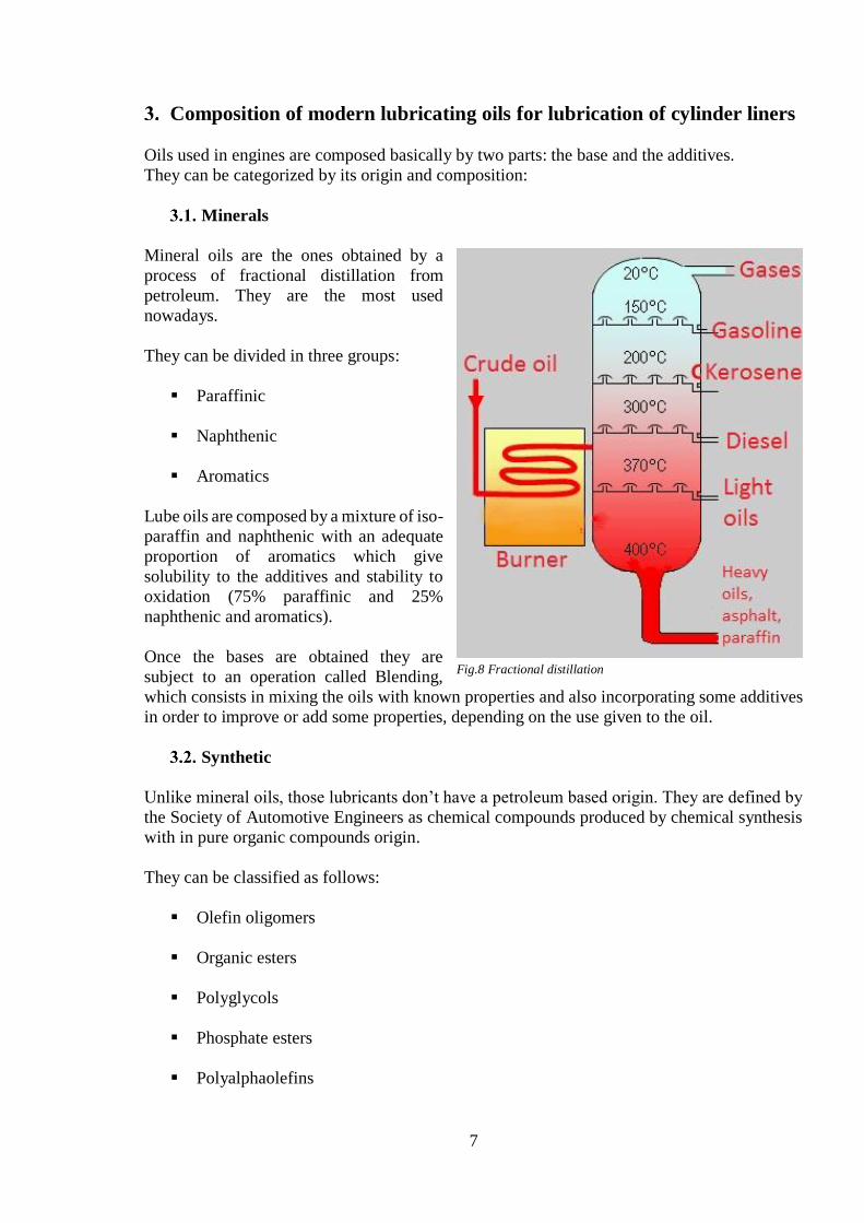
Minerals
Mineral oils are the ones obtained by a
process of fractional distillation from
petroleum. They are the most used
nowadays.
They can be divided in three groups:
Paraffinic
Naphthenic
Aromatics
Lube oils are composed by a mixture of iso-
paraffin and naphthenic with an adequate
proportion of aromatics which give
solubility to the additives and stability to
oxidation (75% paraffinic and 25%
naphthenic and aromatics).
Once the bases are obtained they are
subject to an operation called Blending,
which consists in mixing the oils with known properties and also incorporating some additives
in order to improve or add some properties, depending on the use given to the oil.
Synthetic
Unlike mineral oils, those lubricants don’t have a petroleum based origin. They are defined by
the Society of Automotive Engineers as chemical compounds produced by chemical synthesis
with in pure organic compounds origin.
They can be classified as follows:
Olefin oligomers
Organic esters
Polyglycols
Phosphate esters
Polyalphaolefins
Fig.8 Fractional distillation

8
Synthetic oils are more expensive to fabricate and it’s usually designated to high performance
engines. Although, due to their better properties, are sometimes used in regular engines. These
oils can be used in elements working at a very high temperature and in tough working
conditions.
Other advantages to take into account would be their lower viscosity without any loses in their
lubricant power. That means that their performance in cold situations is improved and also they
reduce the mechanical losses in a more efficient way than mineral based oils.
Advantages:
Consistent molecule, free of impurities
Viscosity index (Medium/High/Very high)
Low congelation points
High resistance to oxidation at high temperatures
Disadvantages:
High cost compared to mineral based oils
They require precautions in oil changes (compatibility problems between oils)
Global availability
Observing the pros and cons of the synthetic oils, in comparison to mineral ones, the options
need to be weighted carefully; increasing the cost in lube oil will also increase the life of the
engine but maybe other options are more worthy in a long term.
Semi-synthetics
These lube oils are made from a mixture of variable proportions of mineral oils and synthetics,
with a high amount of additives in order to get the required properties.
These mixtures can have maximum a 30% of synthetic oil. The objective of this kind of oils is
getting similar properties of the pure synthetic oils but without their high costs.
Semi-synthetics oils have a very variables characteristics because there are so many ways of
mixing the synthetic bases with the mineral ones, just by changing the proportions of each one.
But roughly some advantages of this oils are:
It has a greater viscosity index
It resists lower temperatures
Has a lower inflammation point
Resistance to oxidation
Easier engine start in low temperatures

9
Oil Additives and characteristics
As it has been stated before, in order to achieve all these properties it is necessary to add some
additives to the bases.
Oil additives are chemical compounds used to improve the lubricant performance. Most of the
lube oils in the market contain them, weather they are synthetics or mineral. Those oils which
doesn’t have additives basically they cannot protect modern engines.
The use of “supplementary” additives modifies its viscosity and restrict the flow, causing higher
temperatures in operation, greater fuel consumption and imbalance of the original additives.
For that it is really important not to buy cheaper oils and then add additives, despite some
“sparing tips”.
As it can be seen in the figure 8, each additive satisfies different needs of the engine. Some of
these additives and oil characteristics will be described below.
Density
The concept of density can be defined as the relation between the mass and the volume of a
substance. In lube oils density depends directly from the type of crude and the grade of
distillation applied to it. The analysis to determine the density are made at a 20ºC and with the
help of a densimeter.
The usual values of lube oil density vary between 0.79 and 0.97 gr/cm^3.
Sometimes other characteristics are used to define the oil instead of the density, although they
are directly related with it. One example of that could be the specific gravity, which is the
relation between certain amount of one product and the same amount of distilled water.
Fig.9 Lube oil proportions

10
In the USA it is commonly used the API gravity, which is an arbitrarily scale that expresses the
oil density measured in API degrees, using the following formula:
º 𝐴𝑃𝐼 =141,5
𝑆𝐺− 131,5 where 𝑆𝐺 =
𝜌 𝐿𝑖𝑞𝑢𝑖𝑑
𝜌 𝑊𝑎𝑡𝑒𝑟
Viscosity
It is defined as the resistance created by the internal friction of the fluid molecules when flowing
among itself, or in a simpler way the fluid’s own resistance to flow. Viscosity is the most
important characteristic for practical purposes because it determines the physical capacity for
maintaining the lubrication. This characteristic will fix the mechanical performance.
Viscosity is not constant, it varies according to different parameters such as pressure and oil
temperature. Because of that the concept of Viscosity Index is needed.
Viscosity index:
This parameter is used for creating a relation between the viscosity variation and the
temperature. The measurement system is based in the arbitrarily comparison between the
cinematic viscosity of the lube oil being studied at 40ºC and other two oils with viscosity index
of 0 and 100 at the same temperature. After that the process is repeated at 100ºC. It can be
summed with the formula below:
V: viscosity index
𝑉 = 100 ·𝐿−𝑈
𝐿−𝐻 where U: oil's kinematic viscosity at 40 °C
L&H: 0 and 100 index of oil’s values at 40ºC and 100ºC
These L and H values can be found in ASTM D2270.
Fig.10 Viscosity index comparison

11
Flash point
It is the temperature at which the lubricant oil in the conditions stablished by the corresponding
normative (for example in Spain it corresponds to normative UNE 7057) gives-off enough
gases to make them inflame momentarily when a flame is applied, without the lubricant being
burnt.
Fire point
Once the flash point is overcame, the vapors will ignite and it will start burning permanently
(at least for 5 seconds). Most tables of properties only show the flash points of the materials,
but it can be assumed that fire points are about 10ºC higher than the flash points.
Freezing point
At this temperature, lube oils stop flowing and solidifies. It is determined by cooling
progressively the lube oil in a test tube until it is possible to put it laying horizontally without
pouring.
Acidity
The acidity present in a lubricant may be caused by the additives that contains. It needs to be
minimum because if not, it will attack the surfaces of the contact parts, mostly the antifriction
material of the bearings. The acidity in lube oils is limited to the 0,03%.
The usual causes of acidity can be summed up as follows:
When oils oxidize they generate insoluble products (resins, varnishes…) and soluble
ones. The soluble ones are organic acids that can attack the surfaces.
If the lubricant reaches high temperatures it create acids that will produce corrosion.
Acidity can be also produced by contamination, it can happen for example in a diesel
engine sump, if the fuel contains high amounts of sulfur it can create sulfuric acid after
the combustion process. For that reason alkaline oils are used to neutralize it.
Alkaline-TBN capacity (by additives)
In order to fight acidity the use of some additives is required. The alkaline capacity is the
neutralizing power of the lube oil towards acids and it is measured by the T.B.N. (Total Base
Number). If the residual TBN of a used oil is analyzed it can show the amount of hours that the
oil change can be postponed.
TNB is measured in the quantity in milligrams of potassium hydroxide (KOH) necessary for
neutralizing all the acid components in one gram of lubricant oil.

12
Capacity against oxidation and nitration (by additives)
Due to the use and high temperatures the lube oil is exposed it oxidize, leading to the production
of esters, ketones or carboxyl acids. Those products contribute to increase the oil’s acidity and
reducing its alkaline reserve. Besides, it also experiments an increase in its viscosity.
The main causes of oxidation are:
High temperatures
Presence of metals such as iron or copper which catalyze the reaction of oxidation
Presence of humidity and other contaminants as dirt or dross
Excessive agitation
A high pressure of the lubricant increases the presence of oxygen diluted combined with
high temperatures, stimulating the oxidation
Oxidation is generally produced in a slow way under 60ºC, if that temperature increases
over 80ºC the resistance to oxidation is halved for every 10ºC of increased temperature
Nitration or nitroxidation is a phenomenon given when nitrogen oxides coming from the
combustion gases reacts with the lube oil, causing an increase in its viscosity and the generation
of varnishes and lacquers.
Detergent and dispersant capacity (by additives)
Detergent capacity can be describes as the capability to avoid or minimize the sludge and
deposits formation on the hot parts of the engine. One way to determine if the used oil has this
capacity is observing if it changes its color after some time of use.
These additives use to contain elements that actuate in the own oxidation of the oil, minimizing
also the corrosive action that it implies.
Dispersity is a property that consists in keeping, as the name suggests, the contaminant
components in the oil dispersed. These components are usually made of partially burned
products during the combustion (ashes, cinder, oxides…).
Detergency and dispersity are reduced according to the consumption of the additives and
degradation of the lubricant.
Anti-foam capacity
Foam is created by the fast ascent of bubbles to the surface. It decreases the amount of supplied
lubricant to the different areas and can harm the components such as the oil pump, which by
aspiring foam will induce to the creation of cavitation and wearing.
The main reasons of foam creation are:
Entrance of air through poorly sealed or defective joints
When oil is introduced to the tank by freefall
Too high volume of flow in relation to the pipe’s diameter
13
Lubricant oils classification:
Besides the classification by the composition of the bases, they can also be classified by other
parameters.
The Society of Automotive Engineers (SAE) at the beginning of the 20th Century established
the first lube oil classification based in viscosity, without taking into account the quality,
additives’ index or the service it was meant for. This classification has accomplished to stablish
as model for an ISO standard.
Viscosity classification
There can be found two types of lubricants (monograde and multigrade) deferring in the
viscosity variation capacity if the circumstances require it. The capacity of fixing the grade of
viscosity does not mean that it will not variate with the temperature changes.
The SAE classification has stablished a norm based in the viscosity of the oil at two
temperatures (-18ºC and 99ºC). This classification just allow to stablish a SAE grade of
viscosity, without alluding to the general quality of the lubricant.
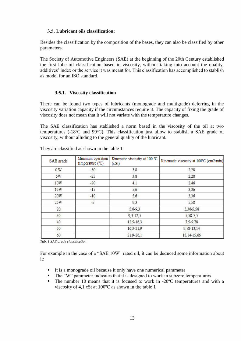
They are classified as shown in the table 1:
For example in the case of a “SAE 10W” rated oil, it can be deduced some information about
it:
It is a monograde oil because it only have one numerical parameter
The “W” parameter indicates that it is designed to work in subzero temperatures
The number 10 means that it is focused to work in -20ºC temperatures and with a
viscosity of 4,1 cSt at 100ºC as shown in the table 1
Tab. 1 SAE grade classification

14
On the other hand in the case of a “SAE 10W 50” rated oil, it means:
It is a multigrade oil because it has two numerical parameters
The first parameter indicates that it behaves when cold as the oil in the first example
The free number indicates that in higher temperatures it behaves as a SAE 50
Although they are still in use, monograde oils which are characterized for maintaining a fixed
viscosity grade have been losing market in engines sector due to its limited capacity of
adaptation to temperature changes.
Multigrade oils with its ability to variate their viscosity grade covering the thermic distance
between two extremes, have become the most used oils in the sector. This obvious due to the
amount of advantages that they have:
More stability facing thermic changes
Low viscosity at low temperatures, so it arrives before to the components
Allows a faster engine start and with less wearing, therefore increasing the useful life
of other components as batteries or electric motors.
Removes the need of seasonal oil changes
Their performance in high temperatures is really good
Less lube oil consumption because of the better sealing they provide
Less fuel consumption because of the reduction of the wear and friction
Some oils are designed specifically to two-stroke engines with special additives that facilitate
the dissolution in the fuel (in the engines that require it). They usually need an oil with a
viscosity grade around SAE 30.
In the case of marine engines which have a separated lubrication, those additives are barely
present because these oils produce far less residues during combustion than the lubrication by
mixture.
Classification by service
Oils can also be classified according to the use they are meant for and which are the qualities
of each type. In order to do so oils are submitted to certain tests. These tests determine different
properties such as:
Capacity against oxidation at high temperatures
Deposits formation control
Viscosity at high temperatures
Fluency at low temperatures
Contaminant emissions control
There are some organisms responsible for certifying and classifying lubricant oils. Unlike SAE
normative, these are based in the quality of the oil. There are basically two organisms:
API (American Petroleum Institute)
ACEA (European Automobile Manufacturers Association)

15
Besides, there are also other organisms focused in military classification or specific
manufacturers focused in an antipollution normative.
API classification is used by the majority of oil manufacturers. Its classification is bases in the
study and comparison of working characteristics and the type of service that the oil will
perform. It’s divided in 2 series: S- for engines using Otto’s Cycle (SN, SM, SL, SJ) and C- for
diesel cycle engines (CH-4, CI-4, CJ-4).
In several cases a lubricant oil will fulfill the specifications of both series.
ACEA classification was constituted in 1996 substituting and old organism already
disappeared, the CCMC (The committee of Common Market Constructors), this classification
is divided in four classes:
Class A, for Otto Cycle engines
Class B, for light Diesel Cycle engines
Class C, specific to protect the scape gases treatment systems
Class E, for heavy Diesel Cycle engines
Nowadays the specific designations for Diesel and fuel engines have disappeared and are now
defined with an unified designation “Class A/B”.
Cylinder oil and System oil
In marine propulsion engines the slow-speed two-stroke crosshead engine has become the most
commonly used, even for land-based power generation plants. The lubrication in these systems
is separated in two parts, cylinder and crankcase or system lubrication.
Cylinder oil
In order to achieve an effective lubrication of the cylinders it is required an oil that is able to
create a tenacious and constant film on the cylinder walls to protect the parts from wear and
make a seal to prevent gases from leaking between the piston rings.
The cylinder oil not only has to be thick enough for the previous reasons it also has to be thin
enough to spread evenly over the whole surface.
The main responsible property of that is the viscosity of the oil. If it is too great the oil will not
spread correctly causing some proportion of the oil to fall in to the bottom of the cylinder while
other parts do not get enough lubrication. Furthermore it will cause high power loses due to
friction, an excessive wear between the rings and the cylinder liner and the leakage that it
entails.
On the other hand, a low viscosity oil will run down the cylinder wall immediately after leaving
the injection holes and not being able to spread out.
Generally the requirement for a cylinder oil is to be SAE 50, although in a few exceptions a
SAE 60 may be used.

16
Speaking of alkalinity a 70 BN (Base Number) oil will cover almost all the uses. It has to be
established a correct balance between the base number and the feed rate and Sulphur level of
the fuel.
As it has been explained before modern oils are blended with several additives. In this case the
special additives for cylinder oils are needed to improve detergency and dispersity properties,
acid-neutralizing properties, oxidation stability, corrosion resistance and load-carrying
properties.
For vessels sailing continuously in Sulphur oxide emission control areas such as the North Sea
and the Baltic, where ships have to use fuel with a maximum of 1.5% Sulphur, 40 or 50 BN
cylinder oils with sufficient detergency are recommended.
System oil
Some time ago system oils used in low speed engines where just straight mineral based oils
without any additives. Even sometimes were used to cool the piston as well as to lubricate the
low temperatures made that the oil did not suffer an excessive stress.
With the creation of modern engines with oil-cooled pistons the amount of heat needed to be
removed increased, still with the need to maintain the engine power ratings. For those reasons,
a straight mineral oil would not be suitable and would create carbonaceous deposits that may
block oil ways. To prevent the formation of those deposits an oxidation inhibitor and detergent
properties must be added to the oil.
The engine needs to be protected against internal rusting and corrosion as well, because of the
possibility of water leakages from the coolers for example. Alkalinity is a property that also
needs to be taken into account and all the strong acids should be neutralized.
To prevent the formation of insoluble deposits a certain amount of dispersant should be added
carefully because a too high dispersity will make the insoluble so finely divided that not even
the filters or centrifuges will be able to remove them. So a correct balance between keeping the
engine clean and allowing an adequate removals of insoluble parts needs to be reached.
Usually, system oils have a TBN value between 5 and 30 and a SAE 30 viscosity classification.

17
Specification of cylinder lubricating oils for slow speed marine engines.
In this section some specific cylinder lubricant oils will be shown. For example, oils made by
Total Lubmarine Company are commonly used, such as the ones explained below:
Talusia HR 70
It is a marine oil that has very high safety margins and it is specially design to fulfill the needs
of slow speed two-stroke crossheads Diesel engines. It also satisfies the requirements and
recommendations of the major engine manufacturers. Thousands of engines under widely
diverse operating conditions are using it, proving its effectiveness.
This oil consists of a highly refined mineral oil with some specific additives. In normal
conditions of use these oils do not present any particular toxic hazard, although it should always
be handled with caution and avoiding contact with the skin.
The main reasons of its popularity are:
- Minimal piston ring and liner wear
- Maximum cleanliness
- Reduced maintenance costs
- Extended periods between overhauls
Engines operating on intermediate or heavy fuels with high Sulphur levels mostly use the
TALUSIA HR 70 (SAE 50, BN 70) due to the benefits that its characteristics can bring to the
oil consumption and optimal engine operating conditions
In this table the main characteristics and the specific rules and methods of measurements can
be seen:
Tab.2 Talusia HR 70 characteristics
18
Talusia Universal
This lube oil has several benefits because it is suitable for use in engines running both high
and low Sulphur fuels. It is specially designed for the cylinder lubrication of slow speed two-
stroke Diesel engines when running with fuel having a large range of Sulphur levels.
This composition makes this oil really useful and able to perfectly adapt with regard to the
neutralization ability of the acids generated during the fuel combustion process.
Due to its versatility TALUSIA UNIVERSAL covers all the special operational need when
using fuel with a Sulphur level between 0, 5% and 4, 5% even in the most stringent conditions
encountered in service. The main benefit of this oil is that there is no need to change to a
special cylinder oil when entering in SECA’s areas (Sulphur Emission Control Area).
Therefore there is no need to store more than one cylinder oil on board on to install additional
lube oil storage tanks and pipework, implying the absence of need to train the crew on correct
switch over procedure.
As the TALUSIA HR 70 this lubricant ensures:
- Minimal piston ring and liner wear
- Maximum cleanliness
- Reduced maintenance costs
- Extended periods between overhauls
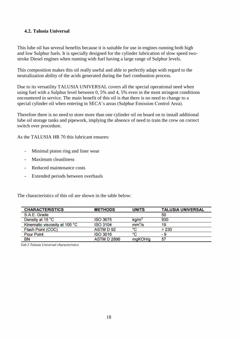
The characteristics of this oil are shown in the table below:
Tab.3 Talusia Universal characteristics

19
The Cylinder Liners lubrication
The cylinder liners are one of the most exposed to heat
and extreme situations of the engine. They are just a
cylindrical piece that separates the cylinder block and
the combustion chamber and piston. This makes it
easier to cool them and to repair the engine just by
substituting them.
The liner is manufactured using superior materials than
the cylinder block. While the cylinder block is made
from a grey cast iron the liner is made from a nodular
cast iron alloyed with chromium, vanadium and
molybdenum. The alloying elements increase the
resistance against corrosion and improve also the wear
resistance at high temperatures.
The cylinder liner will wear with use, and therefore it
might have to be replaced while the cylinder block will
last as long as the engine.
At high working temperatures the liner is a lot hotter
than the jacket and will expand freely diametrically and lengthwise. If there were just one piece
it will cause the fracture of the material due to the thermal stresses.
It can be deduced that the cylinder liner is a vital part of the engine and because of this it requires
a perfect lubrication and it need to fulfill certain needs.
The specific purposes that must serve a cylinder lubrication system when operating with fuels
that contain Sulphur are:
Create and maintain an oil film to prevent metal to metal contact (cylinder liner and
piston rings)
Neutralize the sulphuric acid to avoid or control corrosion
Keep clean the cylinder liner and the piston ring pack
As mentioned earlier, cylinder liners will wear in service. If the engine is correctly operated (no
over loadings, maintaining good temperatures…) and correct grade and quantity of lubricant
oil will help to extend the life of the cylinder liner.
Wear rate vary but as a general rule it can be said that for a large bore engine, a wear of
0,05mm/1000working hours, is acceptable. The liner should be replaced when the wear
approaches the 0,8-1% of the liner diameter. To control this the liner is gauged regularly. Some
really good operated ships with +20 years of operation went for scrap with some of the original
liners.
Fig.11 Cylinder block
20
Four-stroke engines
In this case there are different ways for lubricating the cylinder liners, depending on the size
and type of the engine:
Splash from the revolving crankshaft
Inner lubrication where the oil is supplied from the piston side
In four-stroke engines, the lubricating oil is the same as the system oil used for example in
bearing lubrication.
Although with this system a small amount of lube oil by-passes the piston rings, ending up in
the combustion chamber and being consumed, one of the piston rings is responsible for scraping
the surplus oil back to the engine’s oil pan where is drained, cleaned an recycled.
Usually a well maintained large engine will only consume 0,5 g/KWh of lubricating oil.
The splash system is no longer used in automotive engines because of its low lubricating
efficiency. It is widely used in small four-cycle engines for lawn mowers, outboard marine
operation, etc.
All the circulating oil is always drained or returned to the drain tank, it is very important to keep
clean the lubricating oil. Solid contaminants or water held in suspension will be removed using
centrifugal separators. The separators are working continuously in order to get the most pure
lube oil.
In the case of inner lubrications, oil is supplied through drillings in the liners. These machined
grooves spread the oil circumferentially around the liner and the piston rings will assist in
spreading the oil up and down. The oil needs to be of a high alkalinity to combat the acid attack
from the Sulphur in the fuel.
Most modern engines, times the injection of oil using a computer that has inputs from the
position of the crankshaft, the load of the engine and its speed. The correct amount of oil can
be injected by opening the valves when the piston ring pack is passing the injection point.
Two-stroke crosshead engines (CLU3)
Most of this kind of engines are fitted with an independent system just for cylinder and piston
lubrication. These systems use separate oil pumps to supply pressurized oil to the liner. The
cylinder oil is stored in tanks and transferred daily to a small capacity tank by gravity from
which will pass to the cylinder lubrication system.
In two-stroke crosshead engine, the piston scraper ring does not exist meaning that the cylinder
oil is not recycled and reused. It can be said that once the oil has left the lubricating system is
virtually “lost”. That shows the importance of the oil dosage.
The lubrication is made regardless of the engine size and supplied from an external lubricating
device via quills in the cylinder liner.

21
These lubricators are single-acting reciprocating high pressure pumps which pumps lube oil at
each stroke, on the liner surface.
This system works on the once-through principle using a high-alkaline oil (SAE 50 i.e.) fed to
the surface of the liner through hydraulically actuated quills. The oil supply rate is adjustable
and metered to suit the age and running conditions of the piston rings and the liner.
Lubricating Accumulator
A hydraulic accumulator is a device that stores potential energy by compressing a gas, spring
or a raised weigh to exert force against a relatively incompressible fluid.
They are used in fluid power systems to accumulate energy and release it in pulsations. A
hydraulic system that uses an accumulator can use a smaller fluid pump because it stores energy
in periods of low power demand. The energy is available for an instantaneous use and released
at a rate many times greater than a pump alone could supply.
There are basically four types of accumulators as shown in the figure (x). The weight loaded
type was the first created but is much larger and heavier than modern piston and bladder types.
Both weight and mechanical spring type are almost in disuse today. The hydro-pneumatic types
use a gas as a spring cushion. The gas and the fluid are separated by a thin diaphragm or a
piston.
Fig.12 Quill’s distribution Fig.13 Lubricant injection
Fig.14 Accumulators types

22
In the cylinder liner lubrication are fitted at the outer end of the quill. They deliver oil through
a non-return valve only when the cylinder pressure is lower than the accumulator pressure. The
diaphragm is pressed downwards by a spring force. This creates an oil pressure higher than the
charge air pressure in the combustion chamber. When the charge air pressure falls below the
accumulator pressure oil flows into the cylinder.
In case of the accumulator failure, oil delivery will not stop and will be controlled by the
cylinder lubrication pump’s stroke.
Lubricating Quills
Quills are non-return valves screwed into the liner at the liner oil grooves. They help to moisten
the pressure pulsations in the supply line preventing the gases made by the combustion to enter
back into the oil line and also provide of storage to pressurized oil in the accumulator. Each
cylinder has usually two or more quills, creating a circumference as shown in fig. 12.
Usually, each quill is connected by a separate pipe. The cylinder of the quill needs a non-return
valve in order to eliminate pressure pulsation in the delivery pipe and to prevent the gases to go
in. Because of that, the delivery pipe keeps full of oil even when the engine is stopped. It has
to be placed as close as possible to the liner, otherwise the exhaust gasses will enter the line and
deteriorate the oil before it can get to the cylinder. The quill is isolated from cooling water by
a sealing pipe which allows an easy removal of the quill.
The key is to ensure a proper distribution of the oil on the cylinder liner running surface. The
challenge is not only to ensure that the oil film on the cylinder liner is well maintained but also
continuously refreshed in order to provide enough additives for the acid neutralization and
cleaning processes.
Lubrication principle
This systems consists of a multi-element pump unit driven by an electric motor, and a
progressive distributor for each cylinder with a number of quills with a spring membrane
accumulator. The unit supplies the cylinder lube oil to the distributors, ensuring an equal
distribution of the oil to each individual quill. As explained in the accumulators, when the
pressure inside the cylinder at the quill level, which is normally located in the upper third of the
Fig.15 Accumulators types

23
liner, is sufficiently low, the oil is released by the spring force of the accumulator. The pressure
inside the cylinder is lower than in the accumulator twice for every revolution.
When the piston is moving down during
the expansion stroke and when the
piston is moving up as the piston rings
pass the lubricating grooves.
The system releases a small amount of
oil to the cylinder liner in each cycle, but
this release is not timed. The feed rate is
controlled by disc settings in the pump
unit, and along with the variation of the
rotational speed of the driving electric
motor. The CLU3 system is simple,
robust and very reliable but it requires an
oil feed rate in the range of 1.0 to 1.6
g/kWh.
CLU3 and CLU4 lubricating systems
In two-stroke engines, lubricant feed to the respective lubrication point (quill) is synchronized
to piston positioning either mechanically (System CLU3) or electro-hydraulically (System
CLU4).
For years the cylinder lubrication systems for large 2-stroke crosshead diesel engines have been
developed along with the special lube pumps for use in conjunction with the actuators to ensure
efficient, load-dependent lubrication of the cylinders. In addition to the existence of CLU3
system (the one that has been explained) with its system-related advantages such as high
reliability, ease of operation and simple maintenance, a new kind of electronically-controlled
lubrication system has been developed, CLU4. The aim of that system’s development was to
reduce even more the oil consumption in the cylinder liners. Moreover, more attention has been
paid to the fuel and lubricant composition.
When the Master Control Unit evaluates the load factors, such as engine speed, load or starting
status, it optimizes the cycle rate and metering instantaneously. With an optimal system design
and adjustment it is possible to cut off oil consumption even more approximately to 0.8g/kWh,
reducing this way the use of valuable resources.
The new CLU4 electronic systems achieves a really good performance results with the help of
latest control electronics. The special quills in the wall make it possible to wet every point of
the piston.
This system consist basically in timed lubricators in each cylinder, 6 to 8 outlet ports with
external monitoring electronics, specially developed master control unit and quills and a filter
system that measures the total oil consumption. The oil supply is centralized and is activated
by the engine’s management system before its start. Thanks to that the oil is already available
before the engine starts.
Fig.16 Lubrication system
24
The lubricating-oil needs of the respective cylinders are determined by the master control unit,
that sends to the quills (with or without spray function) the order to discharge the exact quantity
of lubricant with extreme accuracy.
This will not only give better control of the feed rates but also will avoid the hassle of resetting
the individual screws on the cylinder oil pumps at each instance of fuel change over.
Oil feed rates, wear and economics of cylinder lubrications
Oil feed rates
For many years there has been a perception that the more oil used in the cylinder lubrication,
the better. But this is not true, in fact it has been proved that the main reason for cylinder wear,
broken piston rings and overall poorer cylinder condition is over lubrication.
Over lubrication of a two-stroke engine can harm severely the cylinder condition and lead to
higher wear of the cylinder liner and piston rings, even breakage of the piston rings. Sometimes
when it appears some kind of problem some crew members try to solve it by increasing the feed
rate.
Needless to say, an excess of cylinder oil also means an excess of additives that will, as only
part of the additives will be used for the neutralization of the sulphuric acid, burn off and form
a layer of residues on the piston top land. This residues will touch the cylinder liners wiping off
the cylinder oil from the liner surface.
Oil feed rates should always also be adjusted according to the Sulphur content in the fuel oil.
Especially when are taken into use low Sulphur fuels. With the expansion of low Sulphur
Emission Control Areas (SECA) on the global trade routes and future limits on the amounts of
Sulphur in the fuel oil, normal practices are changing. There is a greater use of dual fuel
handling, which requires switching between high and intermediate BN lubricants according to
the fuel on use. This means that modifying cylinder lubrication oil feed rates becomes a daily
task. The optimization requires daily monitoring of the residual drain oil BN. Actual approaches
are not suitable for this monitoring frequency as it can take several hours to measure each
cylinder.
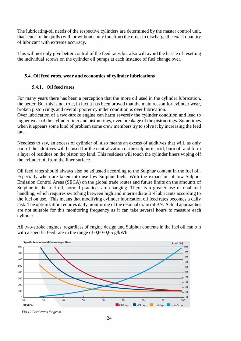
All two-stroke engines, regardless of engine design and Sulphur contents in the fuel oil can run
with a specific feed rate in the range of 0,60-0,65 g/kWh.
Fig.17 Feed rates diagram

25
Slow-steaming
One of the easiest ways to reduce operating costs is reducing the fuel bill. Most vessels are
propelled by a slow speed two-stroke engine directly coupled to a fixed pitch propeller.
Obviously if the speed of the engine is reduced, besides the vessel will slow down, the amount
of fuel required to travel each nautical mile is also reduced. This is because the correlation
between speed and shaft is not linear, but cubic.
Slow steaming has stop being a new practice, it started being used around 2007 to 2008 when
the marked started to experience an oversupply of shipping tonnage, declining freight rates and
increasing bunker prices.
The main reasons for it to become the normal operating procedure are:
The worldwide downturn in the global economy leading to reduce demand for
manufactured goods, reducing the capacity demand
Ship owners are reluctant to lay up vessels and are also a large number of new ships
being delivered
Increase in fuel and other operating costs such as lubricating oil and maintenance
The falling freight rates
The effects of low steaming will become clearer with the following example. If the speed of the
vessel is reduced about 20% the engine power nominal output will be reduced to 45%, reducing
directly the amount of burnt fuel per hour about 60%. If the speed would be reduced by 33%
the actual fuel saving will be 75%. Taking into account that the voyage will take longer the
actual fuel saving will be about 60%, which is a significant amount.
A two-stroke engine operates at its optimum overall efficiency at a load about 80% .When the
engine is designed, the auxiliary systems are optimized for the engine running at between 70-
85% load. If the load drops below 60% other problems start to show up and they will interfere
with the engine performance and operation. These problems will be described below.
Excess cylinder oil fouling and gumming
The oil fouls in the ring grooves leading to sticking piston rings. Also fouling of the
turbocharger nozzle ring ant turbine blades. Unburnt cylinder oil can build up in the exhaust
manifold that may cause an exhaust manifold fire and uncontrolled over speed with the
subsequent failure of the turbocharger.
It is recommended that when slow steaming, the engine load is increased to full power at least
30 minutes a day, or at least 1 hour twice a week to help burn off these deposits. Engines fitted
with MAN Alpha lubrication system or with Pulse Lubrication System by the use of computers
and angle sensors are better at providing adequate lubrication for low load running.

26
Excessive liner wear:
Due to the slower piston speed the wear in the cylinder liners increases. This is partly linked to
the cylinder lubrication. If the speed is reduced too much, the rings will not be able to build up
the necessary lubricant oil film between the ring and the liner. But overall, lower piston speeds
will reduce the effective hydrodynamic film that will prevent the liner to get excessively wore.
Cold corrosion
Cold corrosion is given when the sulphuric acids attacks the liner walls in an engine and
corrodes the liner surface. The abnormal corrosion then creates an excessive wear of the liner
material. It has become an issue in modern engines which are now designed to comply the Tier
II NOx regulation and Energy Efficiency Design Index (EEDI) guidelines. To meet the new
regulations, engine cylinders must operate under increased pressures and reduced operating
temperatures.
This creates conditions below the dew point that allows water to condense on the cylinder liner
walls. That condensation combined with the Sulphur from the combustion process will create
sulphuric acid that will lead to the cylinder liner wear or cold corrosion, requiring expensive
replacement.
It is usually given in the engine cylinder and in heat exchangers. It can be kept under control to
certain degree by rising the temperature of the cooling water.
The best way to identify the causes is by constantly monitoring the condition of the cylinder.
Cold corrosion is a bigger deal in the latest engine designs but it also impacts earlier engine
designs modified for low-load operation (or low-steaming). These modifications may include:
turbocharger cut-out, variable turbocharger nozzle rings, exhaust gas by-pass valve, etc. This
modification can cause moderately corrosive issues or even severe ones.
Fig.18 Worn piston caused by cold corrosion Fig.19 Cylinder liner
27
Cost saving
If it was seen as an industry, large two-stroke marine diesel engines used in over 30.000 ships
worldwide, was an excess of 2 billion USD in cylinder oil over lubrication. In addition, over
1,25 million tons of unnecessary contaminated drain oil need to be disposed because sometimes
4 times the normal level of lubricant required is used.
Over-lubrication in this kind of engines can cost the managers and owners of the ships over
100.000 USD per year per ship. Reducing or controlling the cylinder lubrication oil feed rate,
always with manufacturers guidelines, can prevent this loss. Another advantage is that it will
detect the problems long before they can be detected using conventional means by the
engineering crew of the ship.
On the other hand under-lubrication with the risk of suffering cold corrosion would cost
between 150.000 and 250.000 USD for an unexpected cylinder liner loss.
The best way of doing this is carefully monitoring the performance of the engine and precisely
studying of the chemical composition of the cylinder drain oil. It is recommended to monitor
the levels of both metallic and non-metallic elements separately in order to understand where
corrosive wear is originated. By this a complex model of exactly what is happening within the
engine can be build, showing the best ways to reduce oil feed rates and improve combustion.
Besides that, the amount of wasted cylinder drain oil than needs to be disposed is reduced.
With all this process the reliability of the engine will improve and the time between overhauls
will be increased.
Over-lubrication combined with slightly imperfect combustion is one of the chief avoidable
costs. It causes piston deposits which decrease the efficiency of the combustion process and
increase the engine wear as well as increasing the generation of NOx and air polluting particles.

28
Man B&W Alpha Lubrication system for modern crosshead engines
cylinder liners lubrication
Alpha Adaptive Cylinder Oil Control (Alpha ACC)
The Alpha ACC is based on an algorithm that control the cylinder oil feed rate or oil dosage,
proportional to the Sulphur content in the fuel. To explore the potential savings with the Alpha
ACC, it has been done a large scale research among a number of owners of their MAN Diesel
& Turbo engines in service. The results showed really good results especially with respect to:
Cylinder oil consumption, particle emissions and combustion chamber wear, showing
substantial annual savings and a payback of less than two years. This system can be
implemented on all MC engines and their compact version MC-C.
Main Components
Pump Station and Starter Panels
The pump station consists of two individually operating pumps, heating
coil, filters and a suction tank. The power supply to the pump station
starter panels is taken from two separate circuit breakers, one supplying
each pump.
Lubrication Units
Each cylinder has its own lubrication unit, and each of them comprises
two lubricators for 98-70 bore engines and one lubricator for medium or
small bore engines. Each lubricator unit is equipped with one
accumulator with pre-pressured nitrogen at 25-30 bar on the inlet side,
and one accumulator on the outlet side (for each lubricator), pre-
pressured at 1,5 bar. Depending on the engine type and design each
lubricator could have in 3, 4, 5 or 6 lubricating pistons, one feedback
pickup and one solenoid valve.
Fig.20 Pump station
Fig.21 Alpha lubricator

29
Alpha Lubricator Control Unit (ALCU)
It is composed by three main electronic components that are comprised in one steel cabinet and
the so-called ALCU. These three components are:
Master Control Unit (MCU)
Backup Control Unit (BCU)
Switch Board Unit (SBU)
The 24 V DC power is supplied from two individual power sources, from different breakers in
the UPS units.
Load transmitter
The load transmitter is connected to the fuel rack, thereby
continuously transmitting the fuel index % to the MCU,
which calculates the engine load from this information and
the detected engine rpm.
Fig.22 Alpha Lubricator Control Unit
Fig.23 Load transmitter

30
Trigger system (Shaft encoder)
The shaft encoder is connected to the fore end of the crankshaft,
and the signals are transmitted to the computer panels via a
terminal box. For engines on which the rank shaft fore end is not
available for angle encoder installation, a trigger ring and
tachograph pickups are installed at the turning wheel.
6.2.6 Backup trigger system
The backup trigger system comprises two tachograph pickups in
a box at the turning wheel, thereby transmitting the engine rpm
to the BCU. The backup pickups are also connected to the MCU
for surveillance purposes.
Human Machine Interface (HMI) panel
On the HMI panel, individual cylinder
lubrication adjustment is possible, various values
and alarms are displayed, control buttons for the
pump station are available, and manual execution
of pre-lubrication is possible. As standard the
HMI-panel is mounted in the engine control
room.
It has a three-position mode switch that enables
de selection between:
Auto-mode – BCU takes over
automatically, if lubrication cannot be
maintained by the MCU. If the BCU has
taken over the control, this mode can only
be cleared by manually switching to
MCU-mode, and back to Auto position.
MCU-mode – Forced MCU control.
BCU-mode – Forced BCU is in control.
Fig.26 Human Machine Interface panel
Fig.25 Backup trigger
system
Fig.24 Trigger system

31
Working Principle
Cylinder lubricating oil is fed to the engine at a pressure of 40-50 bar by means of a pump
station usually mounted on the engine or sometimes placed in the engine room. The oil fed to
the injectors has been pressurized by one or two Alpha Lubricators located on each cylinder
and equipped with small multi-piston pumps.
The MCU controls the oil injection by activating a solenoid valve situated on the relevant
lubricator. A feedback signal from each lubricator indicates that the injection has taken place.
This is shown be Light Emitting Diodes (LEDs) on intermediate boxes for each cylinder.
Timing is bases on two signals from the angle encoder, a Top Dead Center (TDC) cylinder
marker and a crankshaft position trigger. The alpha lubricator System is normally timed to inject
the cylinder oil into the piston ring pack during the compression stroke.
The cylinder lubrication is based on a constant amount of oil being supplied via injection. The
specific feed rate is controlled by variation of the injection frequency. This frequency is
calculated from index and speed, and is usually proportional to the engine Mean Effective
Power) MEP. However, a power Mode or RPM Mode is possible.
The basic cylinder oil feed rate at a Maximum Continuous Rating (MCR) of 100% is calculated
as a correlation between a number of injections/rpm and the stroke of the lubricators. On the
HMI panel, adjustment of lubrication feed rate for individual cylinders is possible between 60%
and 200% although default mode is 100%.
During normal operation of the system it is controlled by the MCU. If any failures are detected
in the system a common alarm is activated in the control room. The detailed alarm reference is
displayed on the HMI panel. If a critical failure in the MCU is detected, then the BCU
automatically takes over control (only if the control switch is set in “auto” position). An
indication lamp “BCU in control” is lit on the HMI panel in newer installations and elsewhere
in older ones.
The BCU is based on a random timing and RPM mode. The injection frequency is adjustable
on the BCU and is normally, as minimum, set to the basic cylinder oil feed rate for the engine,
plus 50%. Prior to start-up, the cylinders can be pre-lubricated and, during the running period,
the operator can choose to increase the lube oil feed rate by 25%, 50% or 100%.
The guidance values for automation can be seen in the following table:
Tab.4 Automation guidance values
32
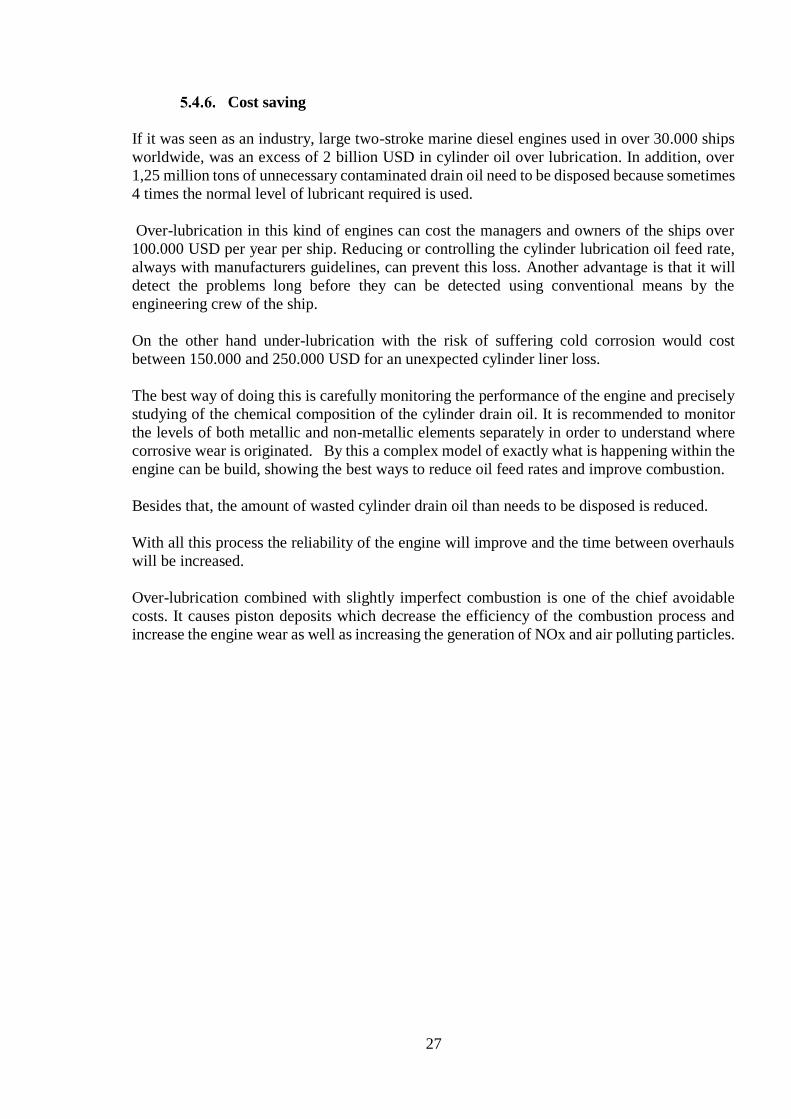
Fig.27 Alpha control system
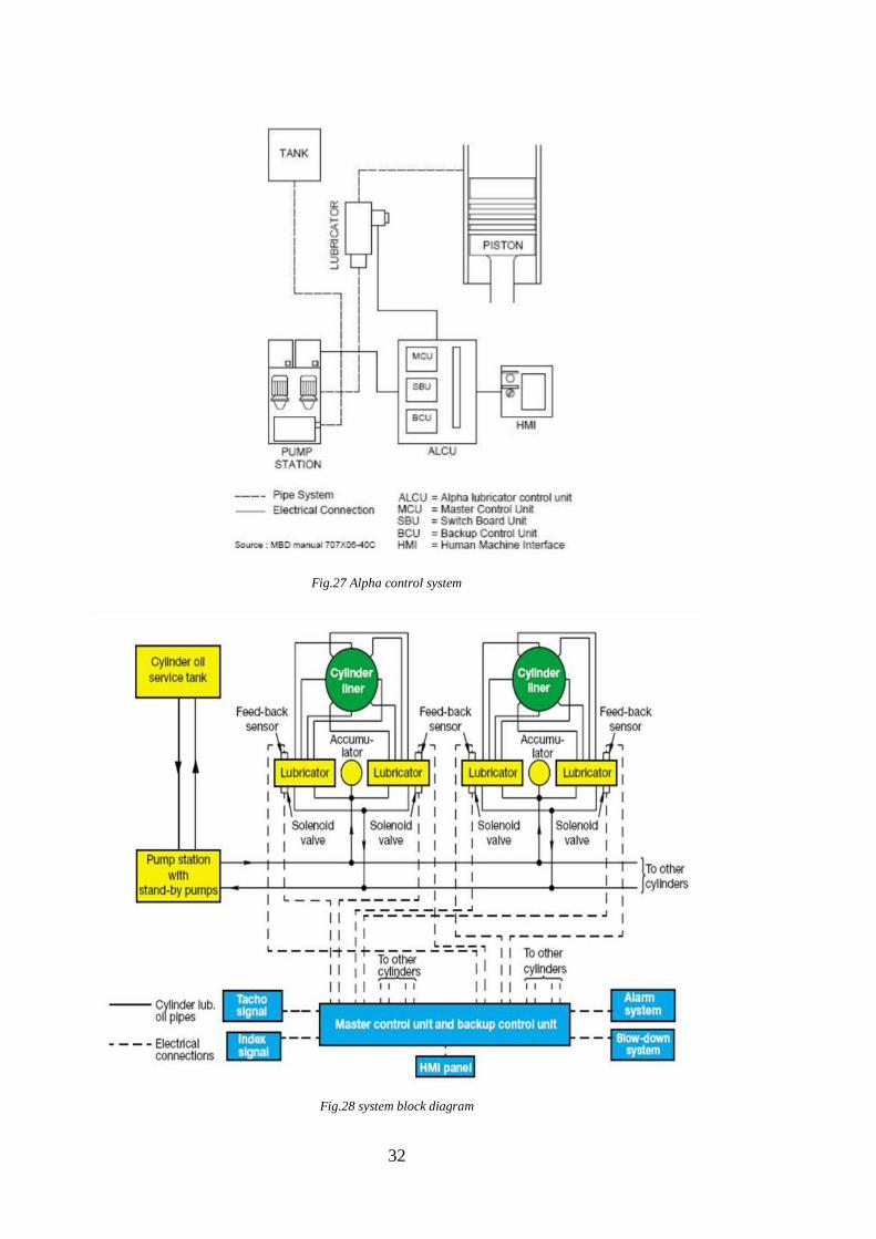
Fig.28 system block diagram
33
Wärtsilä Pulse Jet Lubrication system for modern crosshead engines
Main Components
Pulse lubricating module: consisting of a dosage pump with electronically controlled timing
Lubricators: up to eight in a single row around the cylinder liner
Servo oil supply unit (on RTA engines) or pressure reducing unit (on RT-flex engines)
Control system
Crank angle sensors
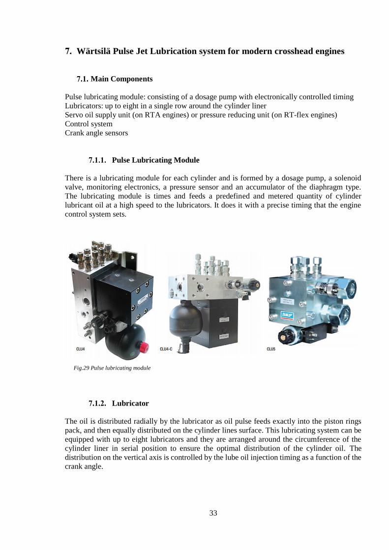
Pulse Lubricating Module
There is a lubricating module for each cylinder and is formed by a dosage pump, a solenoid
valve, monitoring electronics, a pressure sensor and an accumulator of the diaphragm type.
The lubricating module is times and feeds a predefined and metered quantity of cylinder
lubricant oil at a high speed to the lubricators. It does it with a precise timing that the engine
control system sets.
Lubricator
The oil is distributed radially by the lubricator as oil pulse feeds exactly into the piston rings
pack, and then equally distributed on the cylinder lines surface. This lubricating system can be
equipped with up to eight lubricators and they are arranged around the circumference of the
cylinder liner in serial position to ensure the optimal distribution of the cylinder oil. The
distribution on the vertical axis is controlled by the lube oil injection timing as a function of the
crank angle.
Fig.29 Pulse lubricating module
34
Servo Oil Supply (RTA engines)
Exclusively for the RTA engines a separate servo oil supply unit is provided. This unit includes
two gear pumps, one of them is working by supplying the lubricating module with servo oil
taken from the main engine lube oil system while the second one is just in standby. The servo
oil supply unit also includes a pressure limitation and safety valve, a pressure gauge, a pressure
sensor and a shut-off valve.
Pressure reducing unit (RT-flex engines)
In the case of RT-flex engines, servo oil is drawn from the engine’s oil system through a valve
that reduces the oil pressure from 200bar to 50bar. Some pressure transmitter monitor the
reduced pressure and they are connected to the alarm system. The pipes of the system are
SOLAS compliant. It is possible to adjust the pressure that will be reduced and the level is
shown on a pressure gauge.
Crank angle sensors
To be able to control and time the oil (and fuel) injection the control systems must know the
crank angle of the individual units. To do this two crank angle sensors are fitted at the free end
of the engine. These sensors have an accuracy up to 0.1º. The computer automatically
compensates for twists in the crankshaft when relating crankshaft position to cylinder pressure.
The functional objective of these sensors is to determine the position and/or the rotational speed
of the crank. Engine control units use the information transmitted by the sensor to control the
timings of different components.
Sometimes, the sensor may become burnt or worn out, most likely for the extreme heat
exposure. Many modern crankshaft sensors are closed units and therefore they will not be
damaged by water or other fluids.
The first sign of a crankshaft sensor failure is usually the refusal of the engine to start when hot
but will start again once the engine has cooled.

35
Working Principle
Pulse Lubricating System works under the basic principle of delivering metered quantities of
cylinder lube oil under pressure at the precise time and directly and exactly into the piston ring
pack, from where it will be distributed around the cylinder liner.
Each lubricating module has two separated supply lines, one for cylinder lube oil and servo oil.
It communicates with the MCU through a duplicated bus system that sends the signal to the
solenoid valve and processes the data from the pressure transmitter. Every module has a
redundant power supply.
Control and monitoring of the Pulse Lubricating System (PLS) is managed by the Wärtsilä
Engine Control System (WECS). Once it switches the solenoid valve in the lubricating module
to the open position, servo oil flows to the drive side of the lubricating module’s central piston.
When it is actuated it feeds the cylinder lube oil to the metering conducts and then discharges
it from the lubricators at high pressure.
The cylinder oil is accurately supplied at defined positions of the piston in motion. This position
is constantly controlled and monitored by the control system from interpreting the signal given
by the crank angle sensor.
When the lubrication work cycle ends, the directional valve in the lubricating module drives
the servo oil to the return-flow side of the central piston which will then return it to its initial
position. The metering chambers is filled again with lube oil to be ready for the next cycle.
The quills of the PLS are mounted in the upper third of the cylinder liner, as the CLU3 system,
but thanks to the PLS pump the injection of lube oil is independent of the pressure in the
cylinder. This injection time is in the range of 8-10 ms, making possible the timed injection.
Fig.30 Wärtsilä pulse lubricating system diagram

36
Control and Monitoring System
Pulse Lubricating System is controlled and monitored by the WECS which is based on the
Wärtsilä RT-flex system. The communication between the Advanced Lubricating Module
(ALM-20) and the MCU is made by means of a bus system. Once initiated the pulse lubrication
by the engine control system, all the electronics associated with the respective lubricator
activates the solenoid valve. When a pressure sensor sends a signal to the ALM the lubricating
pulse is triggered (electro hydraulically). When the pressure is within the programmed range,
another signal confirms that the lubricating cycle has been successfully executed.
In case of any error such as lubricator blockage, lubricant shortage, lack of hydraulic drive
power or an incorrect valve shut-off, a local fault signal is sent to the WECS.
Comparison between mentioned systems
Disadvantages of Accumulator and Quill Systems (CLU3)
As it have been proved above, the most important factor in cylinder liner lubrication is accurate
timing. The lubricant oil must be injected exactly into the cylinder when the piston is in the
optimal position. Despite the economical factor, the efficiency, the reliability and ease of
operation and maintenance of the CLU3 systems, they cannot obtain the optimal timing in
lubrication and will only operate, as described, as long as there exist pressure difference, leading
to a higher oil consumption and all the other factors that, in the end, will be traduced as higher
economical loses.
Advantages of Alpha Lubricator System
This system easily show some clear advantages with the older systems as CLU3. The injection
is made directly into the piston ring pack at a very high pressure. One of the most important
improves is that the timing in this case is made electronically meaning that is very precise in
time. By doing this the oil losses are reduced to the minimum and the correct feed rate is given
proportionally to Sulphur content. The control of the lubricant oil feed rate is precise and very
easy to control. Other benefit of this system is that it pre lubricates the cylinder before the
engine start, avoiding wear of several metal components.
Advantages of Pulse Lubricating System
On the other hand, PLS has its own advantages. Although some of them are shared with the
Alpha Lubricator System for example the capacity of reduce the oil feed rate, and by this
reducing operating cost, or the precisely timed injection of lubrication and metered quantities
of lube oil, it improves also the distribution of the cylinder oil on the liner by means of its pulse
jet system. The amount of fed cylinder oil is proportional to the Sulphur content of the fuel as
well.

37
Estimation of cylinder liners lubrication quality
Purpose of lubricant oils analysis
Looking after lubricant oils is an essential part of any machinery maintenance. The lubricating
oil is often the only thing that separates the metal surfaces of the engine, journal, hoist and
compressors, so without it the engine could not function effectively. Oil analysis should
therefore be a priority to any maintenance staff or engineer in order to ensure that all the
machinery is able to run as smoothly and as efficiently as possible. It will not only improve the
machinery efficiency but will reduce also their downtime, having a high impact on output and
costs.
Lube oil analysis is the most well-established monitoring methods. The information that used
lube oil can supply can give very early warnings regarding the health of the equipment in
contact with it. These test are not made to study the re-usability of the oil, they are made to
study the condition of the equipment that the oil is in contact with.
The routine test on lube oil samples will be explained but basically they include:
Viscosity at 40ºC and at 100ºC
Water and soot content
Acid and base numbers
ISO codes fulfilling
PQ index
Spectrometric analysis.
Ferro-graphic and microscopic analysis
The test suites are selected according to the equipment and the type of lubricant in use.
There are different methods and equipment supplied by some companies to do these test
including:
On-board Cylinder Monitoring solutions: Allowing cylinder and liner conditions to be
measured and monitored on-board the vessel.
Sensors: Which permit 24/7 monitoring of key performance indicators. Especially for the
protection of high value assets where failures are unpredictable or especially disruptive.
Used Oil Analysis Kit and Labs: They are specially designed for remote plants that do not
have and easy access to laboratories. Some of the kits are usually in vessels for that reason and
provide an acceptable accuracy.
38
Lubricant oil analysis
There are three main categories of oil analysis: fluid properties, contamination and wear debris.
Fluid Properties
This type of analysis is focused on the identification of the oil’s current physical and chemical
state as well as its remaining useful life (RUL). By this analysis it is possible to tell if the oil
inside the engine match the specified oil identification or if the correct oil and additives are
being used.
Contamination
The main use of these tests is detecting the presence of destructive contaminants and narrowing
down the probable sources of them. By means of them it can be determined if the oil is clean.
If it is not what types of contaminants, where are they originating or if there is any internal
leakage can be determined.
Wear Debris
This form of oil analysis determines the presence and identification of particles produced as a
result of mechanical wear, corrosion or other machine surface degradation. It is possible to
determine if it exist an abnormally degradation of the machine, if wear debris is produced or
from which internal component is more likely to be originated the wear.
It has to be taken into account that just with oil samples is very difficult to determine exactly
what is happening and to interpret the given data. It is necessary to know some crucial details
about the machine such as:
The machine’s environmental condition (temperatures, humidity, vibrations…)
The originating component (steam turbine, pump…)
Oil type currently in use
If proper sampling procedure is being done
Total operating time of the sample
Any other unusual activity involving the machine that could affect the lubricant
Oil Analysis Tests
For a standard piece of equipment the set of tests will consist of “routine” tests. If any additional
testing is needed to answer advanced question or of there exist de doubt of a malfunction, these
will be considered as “exception” tests. Routine test vary based on the originating component,
the environmental conditions, etc., but should almost always include viscosity tests, elemental
analysis, moisture levels, particle counts, Fourier transform infrared (FTIR) spectroscopy and
acid number. Other tests based on the originating equipment will include analytical ferrography,
ferrous density, demulsibility and base number testing.

39
Wear Debris Analysis
Wear debris analysis (WDA) is a non-intrusive way to evaluate the wear of the components of
the engine without taking them out. Accurate identification of wear debris fragments can tell
which elements are damaged and the nature of the problem which generated the debris, helping
to isolate other causes such as dust contamination, vibration faults, water contamination, etc. It
is carried out on used oils by extracting magnetic particles from the sample using a magnet.
Microscopic analysis of the sample can show if there are any particles. Research has shown that
spherical wear debris can reveal the severity of rolling-contact fatigue wear. Because large
spherical particles (50 microns) are the product of high metal-to-metal contact and high
frictional temperature, their presence is considered a supporting symptom for assessing the wear
severity levels. Along with ferrous density two other tests are commonly performed to analyze
wear debris. These include particle counting and patch microscopy.
Viscosity
There are several methods used to measure viscosity, which is reported in terms of kinematic
or absolute viscosity. Most of the industrial lubricants classify viscosity as is stated in the ISO
3448 regulation, but not all lubricants classified for example as ISO VG 320 are exactly 320
cSt. ISO standard states that each lubricant will be considered inside it as long as its viscosity
falls within 10% of the viscosity midpoint.
Viscosity is the most important characteristic of a lubricant oil. Monitoring the oil’s viscosity
is critical because any changes in its composition can lead to a host of other problems such as
oxidation or thermal stressors. If the readings of viscosity are too low or too high it may be due
to the presence of an incorrect lubricant, mechanical shearing of the oil, oxidation, influence
from fuel, etc.
Some changes may be accepted usually within a marginal limit of approximately 10% and a
critical limit approximately of 20% higher or lower that the original viscosity.
Capillary Tube Viscometer Test Method
The most common method for determining kinematic viscosity in
laboratories utilizes the capillary tube viscometer. In this method, the
oil sample is placed into a glass capillary U-tube and the sample is
drawn through the tube using suction until it reaches the start position
indicated on the tube’s side. The suction is then released, allowing the
sample to flow back through the tube under gravity, using a calibration
constant supplied for each tube. More viscous grades of oil take longer
to flow than thinner grades of oil. This procedure is described in ASTM
(American Society for Testing and Materials) D445 and ISO 3104.
Stating an oil’s viscosity is meaningless unless the temperature at which
the viscosity was measured is defined.
Fig.31 Capillary tube
viscometer
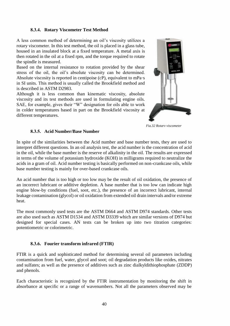
40
Rotary Viscometer Test Method
A less common method of determining an oil’s viscosity utilizes a
rotary viscometer. In this test method, the oil is placed in a glass tube,
housed in an insulated block at a fixed temperature. A metal axis is
then rotated in the oil at a fixed rpm, and the torque required to rotate
the spindle is measured.
Based on the internal resistance to rotation provided by the shear
stress of the oil, the oil’s absolute viscosity can be determined.
Absolute viscosity is reported in centipoise (cP), equivalent to mPa·s
in SI units. This method is usually called the Brookfield method and
is described in ASTM D2983.
Although it is less common than kinematic viscosity, absolute
viscosity and its test methods are used in formulating engine oils.
SAE, for example, gives their “W” designation for oils able to work
in colder temperatures based in part on the Brookfield viscosity at
different temperatures.
Acid Number/Base Number
In spite of the similarities between the Acid number and base number tests, they are used to
interpret different questions. In an oil analysis test, the acid number is the concentration of acid
in the oil, while the base number is the reserve of alkalinity in the oil. The results are expressed
in terms of the volume of potassium hydroxide (KOH) in milligrams required to neutralize the
acids in a gram of oil. Acid number testing is basically performed on non-crankcase oils, while
base number testing is mainly for over-based crankcase oils.
An acid number that is too high or too low may be the result of oil oxidation, the presence of
an incorrect lubricant or additive depletion. A base number that is too low can indicate high
engine blow-by conditions (fuel, soot, etc.), the presence of an incorrect lubricant, internal
leakage contamination (glycol) or oil oxidation from extended oil drain intervals and/or extreme
heat.
The most commonly used tests are the ASTM D664 and ASTM D974 standards. Other tests
are also used such as ASTM D1534 and ASTM D3339 which are similar versions of D974 but
designed for special cases. AN tests can be broken up into two titration categories:
potentiometric or colorimetric.
Fourier transform infrared (FTIR)
FTIR is a quick and sophisticated method for determining several oil parameters including
contamination from fuel, water, glycol and soot; oil degradation products like oxides, nitrates
and sulfates; as well as the presence of additives such as zinc dialkyldithiophosphate (ZDDP)
and phenols.
Each characteristic is recognized by the FTIR instrumentation by monitoring the shift in
absorbance at specific or a range of wavenumbers. Not all the parameters observed may be
Fig.32 Rotary viscometer
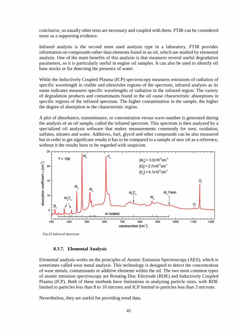
41
conclusive, so usually other tests are necessary and coupled with them. FTIR can be considered
more as a supporting evidence.
Infrared analysis is the second most used analysis type in a laboratory. FTIR provides
information on compounds rather than elements found in an oil, which are studied by elemental
analysis. One of the main benefits of this analysis is that measures several useful degradation
parameters, so it is particularly useful in engine oil samples. It can also be used to identify oil
base stocks or for detecting the presence of water.
While the Inductively Coupled Plasma (ICP) spectroscopy measures emissions of radiation of
specific wavelength in visible and ultraviolet regions of the spectrum, infrared analysis as its
name indicates measures specific wavelengths of radiation in the infrared region. The variety
of degradation products and contaminants found in the oil cause characteristic absorptions in
specific regions of the infrared spectrum. The higher contamination in the sample, the higher
the degree of absorption in the characteristic region.
A plot of absorbance, transmittance, or concentration versus wave-number is generated during
the analysis of an oil sample, called the infrared spectrum. This spectrum is then analyzed by a
specialized oil analysis software that makes measurements commonly for soot, oxidation,
sulfates, nitrates and water. Additives, fuel, glycol and other compounds can be also measured
but in order to get significant results it has to be compared to a sample of new oil as a reference,
without it the results have to be regarded with suspicion.
Elemental Analysis
Elemental analysis works on the principles of Atomic Emission Spectroscopy (AES), which is
sometimes called wear metal analysis. This technology is designed to detect the concentration
of wear metals, contaminants or additive elements within the oil. The two most common types
of atomic emission spectroscopy are Rotating Disc Electrode (RDE) and Inductively Coupled
Plasma (ICP). Both of these methods have limitations in analyzing particle sizes, with RDE
limited to particles less than 8 to 10 microns and ICP limited to particles less than 3 microns.
Nevertheless, they are useful for providing trend data.
Fig.33 Infrared Spectrum
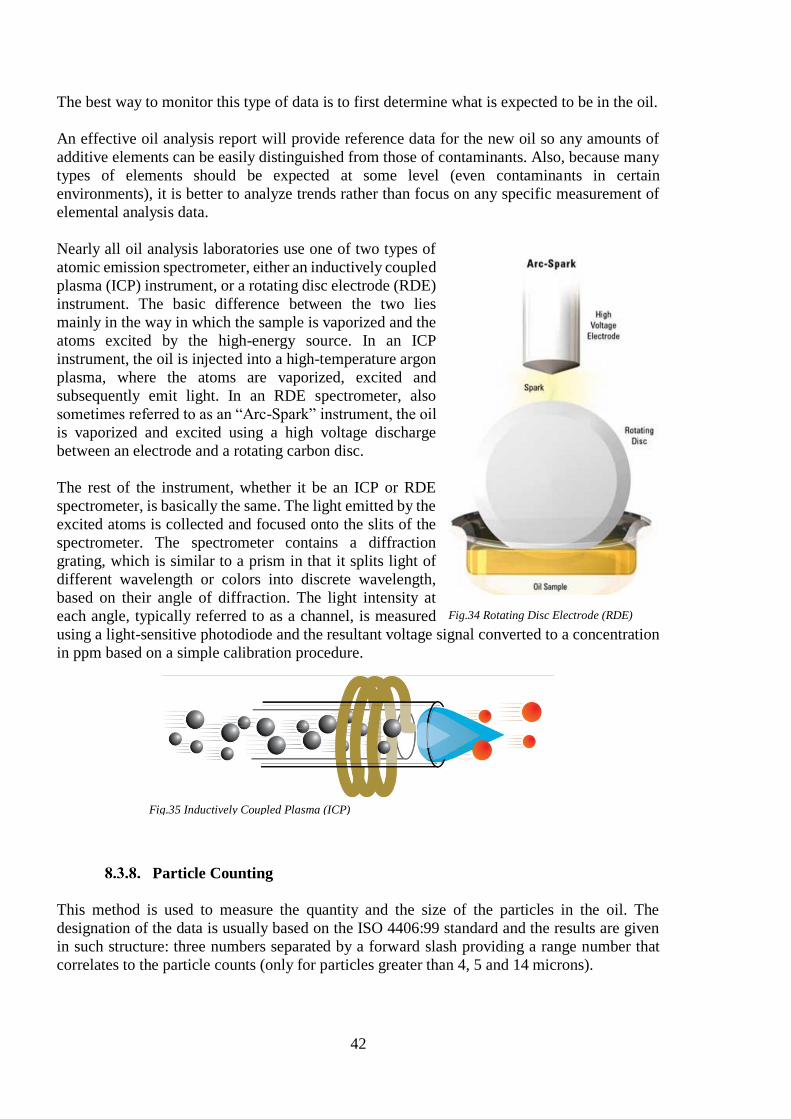
42
The best way to monitor this type of data is to first determine what is expected to be in the oil.
An effective oil analysis report will provide reference data for the new oil so any amounts of
additive elements can be easily distinguished from those of contaminants. Also, because many
types of elements should be expected at some level (even contaminants in certain
environments), it is better to analyze trends rather than focus on any specific measurement of
elemental analysis data.
Nearly all oil analysis laboratories use one of two types of
atomic emission spectrometer, either an inductively coupled
plasma (ICP) instrument, or a rotating disc electrode (RDE)
instrument. The basic difference between the two lies
mainly in the way in which the sample is vaporized and the
atoms excited by the high-energy source. In an ICP
instrument, the oil is injected into a high-temperature argon
plasma, where the atoms are vaporized, excited and
subsequently emit light. In an RDE spectrometer, also
sometimes referred to as an “Arc-Spark” instrument, the oil
is vaporized and excited using a high voltage discharge
between an electrode and a rotating carbon disc.
The rest of the instrument, whether it be an ICP or RDE
spectrometer, is basically the same. The light emitted by the
excited atoms is collected and focused onto the slits of the
spectrometer. The spectrometer contains a diffraction
grating, which is similar to a prism in that it splits light of
different wavelength or colors into discrete wavelength,
based on their angle of diffraction. The light intensity at
each angle, typically referred to as a channel, is measured
using a light-sensitive photodiode and the resultant voltage signal converted to a concentration
in ppm based on a simple calibration procedure.
Particle Counting
This method is used to measure the quantity and the size of the particles in the oil. The
designation of the data is usually based on the ISO 4406:99 standard and the results are given
in such structure: three numbers separated by a forward slash providing a range number that
correlates to the particle counts (only for particles greater than 4, 5 and 14 microns).
Fig.34 Rotating Disc Electrode (RDE)
Fig.35 Inductively Coupled Plasma (ICP)

43
It has been said that particle counting is also a method to determine wear debris but this
statement is conditioned. Particle counting is actually a test for particle contaminant levels, it
cannot distinguish between wear debris and dirt particles, but if it can be determined that non-
ferrous contamination has remained stable, then an increase in the particle count can be
attributed to wear.
A magnet can be used to modify the particle count to ferrous debris only. Although there are
different methods the essence is a magnet that holds back the ferrous debris while the non-
ferrous debris is flushed from the sample and then proceeding to the ferrous debris particle
count.
The method of particle counting is not as important as performing the test properly. It is
important to note that only results from the same method should be compared.
The particle count is an easy test to interpret, assuming the test has been correctly performed.
It is necessary to make this point because there are many factors which can negatively affect
the particle counting. An increasing count is an indication of an increased number of particles
in the oil. Exception tests such as analytical ferrography or patch microscopy would then be
used to qualify the type and source of the particle contamination.
Analytical Microscopy
As said just above, the analytical microscopy is a
technique used to qualify contaminants, including
wear debris in an oil sample. The most commonly
performed variations of this technique are
analytical ferrography and patch microscopy.
Analytical ferrography uses magnetic fields to
separate ferrous debris according to particle size.
As the name suggests, this technique basically
aimed to ferrous particles, but some nonferrous
particles are typically deposited on the substrate
either via entrapment or by magnetic effects
imparted to them by impaction of ferrous
particles.
Patch microscopy, on the other hand, is not only
focused on ferrous particles. All particles above
the membrane pore size are presented on a piece
of filter paper, the filtergram, for examination.
However, patch microscopy does not have the size-separation attributes of the ferrography, so
particle deposition is random.
A modification of the patch test can be performed to analyze both ferrous and nonferrous debris
separately. A magnet is used to hold back magnetic particles while a filtergram of nonferrous
debris is prepared. Then a filtergram of the remaining magnetic debris is made.
Fig.36 Analytical ferrography

44
To correctly decide which test to perform is necessary to make some judgment about the
machine metallurgy and the nature of the contaminant being sought. For example it would not
be a good idea to perform a ferrografy in parts of the engine such as a worm-and-wheel gear
because the majority of the wear particles will be cupric, and therefore non-magnetic. And on
the other hand if is suspected on a reducer with helical gear sets to be in a wear situation, the
analytical ferrography will probably provide far better results than the patch.
It is worth mentioning that for filtered oil systems, a ferrogram or patch which does not show
abnormalities should be treated with suspicion. Assuming that there was a reason to proceed
with the analytical microscopy in the first place, one would then expect to see problems. A good
approach to filtered systems is to remove a section of the filter medium, wash it out in solvent
and perform the microscopy on the extract.
Interpretation is subjective and can be expensive to perform because it is labor-intensive.
Analytical microscopy is a powerful technique which should be used to confirm and qualify
contamination and wear situations identified by the routine tests.
Moisture Analysis
Moisture content within an oil sample is commonly measured with the Karl Fischer (KF)
titration test. This test reports results in parts per million (ppm), although data is often shown
in percentages. It can find water in all three forms: dissolved, emulsified and free. The crackle
test and hot-plate test are non-instrument moisture tests for screening before the Karl Fischer
method is used. Possible reasons for a moisture reading being too high or too low would include
water ingression from open hatches or breathers, internal condensation during temperature
swings or seal leaks.
This test can be defined a technique to determine the concentration of a substance in solution
by adding to it a standard reagent of known concentration in carefully measured amounts until
a reaction of definite and known proportion is completed, as shown by a color change or by
electrical measurement, and then calculating the unknown concentration. The reagents include
alcohol, SO2, a base and I2.
There are 2 types of KF titration: volumetric and coulometric. The difference between them is
primarily in the way the I2 is generated: in volumetric titration, the I2 is included with the
reagents while in coulometric titration, the I2 is generated at an electrode. This method is under
the ASTM E203 standard.
Soot analysis
The soot index is a linear measurement that measures the extent to which the oil has become
contaminated by fuel soot, an unwanted by-product of combustion. The units reported depend
on the spectrometer manufacturer. The measurement really applies only to diesel engines
because the soot measurement on gasoline engines is expected to be very low. In diesel engines,
excessive amounts of soot can be generated by overfueling (air to fuel ratios), incorrect
combustion temperatures, low operating revolutions, restricted intake and exhaust systems, and
faulty turbochargers.
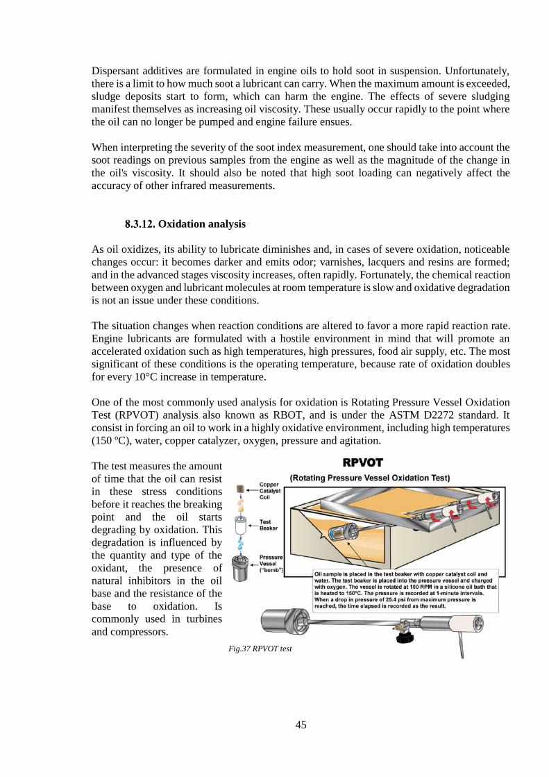
45
Dispersant additives are formulated in engine oils to hold soot in suspension. Unfortunately,
there is a limit to how much soot a lubricant can carry. When the maximum amount is exceeded,
sludge deposits start to form, which can harm the engine. The effects of severe sludging
manifest themselves as increasing oil viscosity. These usually occur rapidly to the point where
the oil can no longer be pumped and engine failure ensues.
When interpreting the severity of the soot index measurement, one should take into account the
soot readings on previous samples from the engine as well as the magnitude of the change in
the oil's viscosity. It should also be noted that high soot loading can negatively affect the
accuracy of other infrared measurements.
Oxidation analysis
As oil oxidizes, its ability to lubricate diminishes and, in cases of severe oxidation, noticeable
changes occur: it becomes darker and emits odor; varnishes, lacquers and resins are formed;
and in the advanced stages viscosity increases, often rapidly. Fortunately, the chemical reaction
between oxygen and lubricant molecules at room temperature is slow and oxidative degradation
is not an issue under these conditions.
The situation changes when reaction conditions are altered to favor a more rapid reaction rate.
Engine lubricants are formulated with a hostile environment in mind that will promote an
accelerated oxidation such as high temperatures, high pressures, food air supply, etc. The most
significant of these conditions is the operating temperature, because rate of oxidation doubles
for every 10°C increase in temperature.
One of the most commonly used analysis for oxidation is Rotating Pressure Vessel Oxidation
Test (RPVOT) analysis also known as RBOT, and is under the ASTM D2272 standard. It
consist in forcing an oil to work in a highly oxidative environment, including high temperatures
(150 ºC), water, copper catalyzer, oxygen, pressure and agitation.
The test measures the amount
of time that the oil can resist
in these stress conditions
before it reaches the breaking
point and the oil starts
degrading by oxidation. This
degradation is influenced by
the quantity and type of the
oxidant, the presence of
natural inhibitors in the oil
base and the resistance of the
base to oxidation. Is
commonly used in turbines
and compressors.
Fig.37 RPVOT test
46
Sulfation analysis
The combustion by-products formed by burning diesel fuel, sulfur oxides and water, readily
combine to form sulfur-based acids. The bulk of these corrosive acids is removed as part of the
engine’s exhaust, but some remain and escape into the engine cavity in blow-by gas where they
are neutralized by additives in the oil, or proceed to attack the thin oil films providing
lubrication for piston rings and cylinder liners.
The testing of Sulfation is usually done by using FTIR which coupled with Base Number Test
and viscosity make possible to determine the extent of oxidation and degradation of the oil.
The sulfate index from infrared analysis is a measurement of the amount of sulfur-based acids
that have reacted with the oil and reflect the amount of sulfation that has occurred. If fuel sulfur
levels remain constant, the sulfate index would be expected to increase continuously with use
until the oil reaches the end of its useful service life, for which the sulfation level or sulfate
index can be an important determinant. This method is under the ASTM E2412 and ASTM
D7415 standards.
At normal operating temperatures, acids remain in a gaseous state in the blow-by gas with
minimal contact with reactive surfaces. However, when an engine experiences lower-than-
normal operating temperatures (such as just after start-up, at shutdown, or when a faulty cooling
system results in continuous overcooling) the acids condense and come in contact with the oil
in the sump, causing the oil to film on exposed metal surfaces. This places an extra burden on
the lubricant because it must neutralize more acid than would be expected during normal
operation. Thus, high sulfation early in the oil’s life often indicates abnormally low operating
temperatures.
Nitration
As with sulfation, nitration is the reaction of the oil with combustion by-products of nitrogen.
These reactions tend to become more pronounced at higher temperatures. Therefore, increased
nitration is often an indication of increased blow-by, as the hot combustion gases react with the
oil. Nitration is rarely mentioned because other problems, such as high top-end wear associated
with blow-by, will manifest themselves first.
Nitration in industrial oil samples is an indication of a thermal breakdown of the oil. This can
occur when the oil comes into contact with extremely hot surfaces, or where excessive aeration,
particularly in hydraulic systems, leads to microdieselling. Though not often seen, an increase
in nitration should be taken seriously.
Acid Number (AN)
The measurement of AN involves a titration where the total acid content of the oil dissolved in
a mixed solvent is completely neutralized by the gradual addition of an alcoholic solution of
potassium hydroxide (KOH). A colorimetric method of determining the end point is effected
by the use of a chemical indicator that changes color as soon as the acid is completely
neutralized. Alternatively, a potentiometric method may also be used.

47
The AN test is performed on nonengine oil samples and is used to quantify the acid buildup in
these oils. An increased AN is a result of oxidation of the oil, perhaps caused by overheating,
overextended oil service, or water or air contamination.
AN limits vary enormously and depend both on Original Equipment Manufacturer (OEM)
specifications and on the oil itself. In some cases, an AN exceeding 0.05 is unacceptable; in
others ANs of 4.00 and higher remain acceptable. As with all other readings, trend analysis is
the best indication of the health of both the oil and the machine.
Base Number (BN)
The measurement of BN involves a complex potentiometric titration where the total alkaline
reserve of one gram of oil dissolved in a mixed solvent is reacted with the gradual addition of
a known excess of an acid solution. The reaction is monitored using a reference and a measuring
electrode, where a graph of voltage (mV) vs. acid added (ml) is then plotted. The end point is
detected from a point of inflection on the graph or, in the case of badly degraded oils, from a
predetermined millivolt reading.
This test applies only to engine oil samples because these lubricants are deliberately formulated
to contain a reserve alkalinity that enables them to neutralize the corrosive acidic by- products
of the combustion process. The BN of an oil is a direct measurement of its alkaline reserve.
Every engine oil has an initial BN that gradually reduces during use.
Typical starting values for diesel engine oils are between 8 and 12. However, marine engines
burning heavy fuel oil need a much higher BN, possibly as high as 80, to handle the harsh
combustion conditions from fuels containing a high concentration of sulfur. A general rule of
thumb is to discard the oil when the BN drops below half its beginning value.
Using a lubricant specifically formulated for diesel combustion in a gasoline engine could also
prove detrimental, highlighting the importance of adhering to equipment manufacturers’
lubricant specifications.
BN measurements are performed only on samples from infrared results flagged for analysis. A
BN can be predicted through the infrared data and, where this prediction is below the specified
limit, a BN test is requested to confirm the degree of degradation evident in the infrared data.
All samples having a predicted BN exceeding a safe limit are reported as having a BN of +6
while the actual result is reported for samples selected for the test.
AN and BN Units of Measurement
The units of BN and AN can be somewhat confusing. Although they are different tests, the
results are both expressed in the same units: milligrams of potassium hydroxide per gram of oil,
represented as mg KOH/g.
The AN of an oil is defined as the number of milligrams of KOH needed to neutralize the acid
constituents in one gram of the oil.
48
The BN of an oil is the number of milligrams of KOH needed to neutralize the acid needed to
neutralize the basic constituents in one gram of the oil.
Gas Chromatography Test for Fuel Dilution
Gas chromatography (GC) is a separation technique used to analyze used engine oils for
evidence of fuel dilution. The technique as applied to fuel dilution measurements is used to
separate and measure two volatile fractions of specified boiling ranges from used engine oil
samples. The first volatile fraction of interest has a boiling range similar to that specified for
gasoline, while the second fraction has a boiling range similar to diesel. The instrument is
calibrated and measurements are reported as a percentage contamination by mass.
The fuel dilution test is typically performed either when a significant drop in sample viscosity
is measured, or when the flash-point test has failed. It is important that the oil brand and grade
are correctly described to your laboratory if problematic samples are to be detected. Special
care is necessary in interpreting results because many factors can influence their interpretation.
Fuels are complex mixtures of organic compounds that are classified into products based largely
on distillation ranges rather than specific chemical data. There are also significant overlaps
between various product specifications, making it sometimes difficult to accurately separate
and quantify fuel mixtures.
49
Cylinder Drain Oil analysis
Used oil taken from the engine through the scavenge bottom drain can be used for cylinder
condition evaluation. Drain oil analysis is also a strong tool for judging the engine wear
condition. Drain oil samples taken in active ACC operation will show if the oil feed rate can be
optimized while keeping the BN above 10-25 mg KOH/g and the iron (Fe) content below 200
mg/kg in the drain oil.
It is important to note that elevated iron values may be experienced as the piston ring running-
in coating gradually wears off. Onboard sets exist, but it is important to get a valid test result
that shows the total content of iron (Fe). Laboratory testing according to ASTM D5185-09 is
the only certain measuring method. The BN must be tested in accordance with ISO
3771:2011(E).
A cylinder oil can be degraded to a certain level where the corrosion level begins to increase.
The level of depletion is different among oil brands and engines, and an individual evaluation
of each engine is therefore recommended.
Cylinder lubricant drain analysis has opened a new source of information to help determine
engine performance conditions, providing the superintendent with additional information to
make engine maintenance decisions. Important to note is that Cylinder Lubricant drain analysis
can detect a problem, such as ring and liner wear, water contamination of the cylinder lubricant,
and piston rod gland leakage, before it would be picked up by conventional methods of
inspection.
Furthermore, by combining cylinder lubricant drain analysis with the physical inspection of
piston condition through the scavenge ports, more precise maintenance decisions can be made.
The need for regular piston inspection is recognized by most operators.
However, the lower educational standard of some ships’ staff may mean that piston inspection
cannot always be relied upon to provide as much valid information about piston and liner
conditions as would be the case with inspection by an experienced superintendent or specialist
engineer.
Sampling
As in most oil sampling procedure, it is recommended that sampling is made while the engine
is running or if it has been shut down recently (maximum 10-15 minutes) depending on the
sampling procedure.
When a diesel engine or any kind of diesel machine is brand new it is really important to take
a sample during the first few hours of operation. Due to infant mortality, the probability of
failure is much higher at the onset of a machines life, which is result of break-in wear and other
possible faults during fabrication.
If the oil has already been used for some time the recommendations are similar. The sample
must be taken when the engine is operating under normal conditions or immediately after
shutting it down so the oil is still at typical operating temperatures. In any case, for reliable

50
results, the engine should have been running at least for an hour. If sampling is not performed
correctly, the integrity of the oil sample can be affected.
There are some “rules” to correctly collect the samples:
The collection of the samples should be done at the same time that engine performance
is being recorded. Engine performance is usually recorded one per month while the
engine is working at a load of 85%-90% of MCR.
Cylinder Drain Oil (CDO) should also be taken at similar engine load.
There has to be a calm sea when taking samples
Stable engine operation (if Load Change Device (LCD) is fitted, has to be de-activated)
Piston rod diaphragm has to be cleaned and free of excessive sludge prior to sampling.
Each oil has its own sampling spot to get a good quality sample and obtain significant results
in the analysis as seen in the chart below:
Sampling
Oil
System oil
New system oil
Line sample from topping up line (once per year)
System oil (crankcase)
Sample from main lubricating oil pump
discharge
Cylinder oil
New cylinder oil
Line sample from line to lubricator pump
Cylinder Drain Oil
One sample from under-piston drain line of each
cylinder
Fuel
Line sample before Fuel Oil Purifier
Line sample befrore Main Engine fuel injection
pump
Fig.38 Sampling procedure chart

51
Procedure
The procedure to collect good samples and following each step is really important to get
significant results and non-altered samples. The procedure is as follows:
1. The first step is the closing of the shut-off cock and the opening of each sampling cock
to blow out any oil or sludge remaining in the cock and line.
2. Keeping both cocks closed for about an
hour or more whilst recording the engine
performance.
3. After that time the sampling cock must be
opened again briefly to drain off a small
amount of oil from the sampling cock and
line. This small amount should be disposed
to waste.
4. Then about 500-1000 ml of cylinder drain
oil should be collected. The container
should be clean for each sample.
5. Sampling cock must be closed and the shut-
off valve re-opened.
6. In order to make sure that the oil is
homogeneous it has to be stirred thoroughly
in the container.
7. Afterwards the oil must be poured into a 100 ml sample bottle, which must be labeled
with the ship’s name, cylinder number and date of collection.
During the collection and labelling of the Cylinder Drain Oil (CDO) samples please take great
care to be sure that each CDO sample bottle is marked with the correct cylinder number. It is
also very important to take new oil samples. In the case of system oil is only necessary to take
new oil samples once a year but for cylinder oil it will be required to collect new fresh oil at
each sampling. New oil samples should not be taken from the Storage Tank Drain (STD),
instead, they should be taken from suitable points on the top-up line.
Fig.39 Sampling points and cocks

52
Analysis reports and trouble shooting
By means of analysis and reports like this during the normal operation of the engine and in each
cylinder it is possible to control and some data can be monitored in order to assess the condition
of the engine.
These reports are very specific and the data that they can collect can be even through different
years. They include graphs, trends, tables of different data (Fe, water, temperature, Sulphur,
BN, feed rate, viscosity, etc) to show the evolution of the engine’s life.
The basic reason to that is to be able to identify any problem the engine is suffering, for
example, the content of Fe in the scavenge drain must be maintained in order to keep the
cylinder liners in good conditions. Beside this analysis also inspections must be done along
with corrections of the feed rate if necessary.

53
Summary
This paper gives an insight into many of the concurrent operational issues observed in two-
stroke low speed engines. Obviously, focus is on issues with the new generation of slow diesel
engines, especially in relation to cold corrosion. Significant progress has been made in order to
suppress this phenomenon. The introduction of BN 100 cylinder oils and modified jacket water
cooling systems have successfully counteracted the influence of cold corrosion on cylinder
liners on the latest generation of engines. As described, further work to optimize the cylinder
liner wall temperature by cylinder liner design is ongoing at the moment.
Cylinder lubricant drain analysis has opened a new source of information to help determine
engine performance conditions, providing the superintendent with additional information to
make engine maintenance decisions. It is important to note is that Cylinder Lubricant drain
analysis can detect a problem, such as ring and liner wear, water contamination of the cylinder
lubricant, and piston rod gland leakage, before it would be picked up by conventional methods
of inspection. Furthermore, by combining cylinder lubricant drain analysis with the physical
inspection of piston condition through the scavenge ports, more precise maintenance decisions
can be made.
The need for regular piston inspection is recognized by most operators. However, the lower
educational standard of some ships’ staff may mean that piston inspection cannot always be
relied upon to provide as much valid information about piston and liner conditions as would be
the case with inspection by an experienced superintendent or specialist engineer. Visual
inspection does, nevertheless, have its limitations for example drain analysis can pick up a wear
problem which has not been noted during visual inspection of pistons, in other words, before
the wear became a serious problem.
As a further step towards a more comprehensive engine performance monitoring service,
engine manufacturers have been collecting engine performance data from selected ships. The
combination of regular monthly engine performance data, photographic records of piston and
liner condition, together with the data derived from cylinder lubricant drain analysis has enabled
a more detailed and specific interpretation of engine performance condition to be provided to
engine operators.
In many ways, the two-stroke world is quite different from the four-stroke world, particularly
in the case when it comes to the testing and validation of new components and systems. A
four-stroke engine can be operated on a test bed for a considerable number of hours within a
reasonable budget, but this would not be the case for a two-stroke engine, at least not for a large
bore, multi cylinder one.
Therefore, most testing and validation of new two-stroke components and systems must be
carried out in service, and a prerequisite for development work is to have access to a number of
vessels.
Testing and validation in service is very often both a time consuming and slow process, because
it requires thousands of running hours. In many cases it would be desirable to accelerate this
process, and modern advanced computer simulation tools are becoming more and more precise
and useful in complement to field tests, but in the meantime full-scale measurements on board
ship are still needed as a reliable source.
54
Analysis of the waste oil, and comparison of the waste oil analyses with new oil analysis,
enables conclusions to be drawn about the combustion and lubrication conditions of each
cylinder unit. A further comparison, of the waste oil from one cylinder unit with the waste oil
from other cylinder units of the same engine, enables comparison of the performance and
maintenance condition of each unit against the other units.
The increase in power has also led to an increase in the acid condensation on the liner wall. In
addressing the subject of corrosive wear there would be no acid condensation if liner wall
temperature is maintained above 1900C, even when operating on a 5% Sulphur fuel and Pmax
of 200bar.
In marine engine field, camshaft replaced electronically controlled engines are popular and the
best ones at the present. Since traditionally camshaft is omitted, this allows a net reduction in
engine weight, initial cost for engine and maintenance costs. Moreover, the traditional camshaft
has the considerable limitation of fixed timing given mechanically by the cams.
Electronically controlled systems used in new Wärtsilä RT-flex and MAN B&W ME series
engines can give complete control of the timing, rate and pressure of fuel injection and the
exhaust valve operation, allowing patterns of operation which cannot be achieved by purely
mechanical systems. So, camshaft-less engines are fully compliant with the IMO Tier Π exhaust
emissions regulations set out in Annex VI of the MARPOL 73/78 convention. In these engines,
camshaft functions are done by hydraulic power.
With the development of the latest control electronics, Pulse Lubricating System and Alpha
Lubricating System provided timed lubrication with reduced cylinder lubricating oil
consumption. By installing these modern systems, feed rate can be adjusted automatically with
respect to engine operating condition, so cylinder oil will not be wasted and cylinder liners are
in good condition for a long time.
From the aspect of long term operation of ship, environmental friendliness and providing
optimum efficiency, owners may consider to equip those modernized system. As modern ships’
engines are constructed in combine with electronic technology, marine engineers become need
to be competent in electronics, apart from mechanical engineering knowledge.
So, by studying modern lubricating systems and composing a thesis, it is sure to be able to
understand and operate these systems while encountering at a certain ship. Moreover, the
contents contained in the thesis will help to have an understanding in lubrication of main
engines.

55
References
Websites
http://www.brighthubengineering.com
http://www.rina.org.uk
http://unimarine-lubricants.com
http://www.marineinsight.com
http://www.marinediesels.info
http://www.machinerylubrication.com
https://ingenieromarino.wordpress.com
https://maquinasdebarcos.wordpress.com
http://www.skf.com
http://lubemec.grouphes.com
http://www.tobul.com
http://www.hmstc.or.kr
http://cursa.ihmc.us
http://cdn.wartsila.com
http://marinestudy.net
http://standards.sae.org/j300_201501
http://dieselturbo.man.eu
http://lot-qd.com
https://www.astm.org
http://www.lubricantes-as.es
http://www.api.org

56
Books and publications
Modern Materials: Advances in Development and Applications, Bruce W. Gonser
Guide to ASTM Test Methods for the Analysis of Petroleum Products and Lubricants, R.A.
Kishore Nadkarni
Técnicas de reconocimiento. Análisis de lubricantes Instalaciones y Mantenimiento, Ramón
Grau UPC-FNB
Service Letter SL2014-587/JAP March 2014, MAN Diesel & Turbo
Advanced Marine Engineering Knowledge (Volume 1), Vikram Gokhale N.Nanda
Running and Maintenance of Marine Diesel Engines, John Lamb, O.B.E, Sixth Edition
Diagnóstico de motores diésel mediante el análisis del aceite usado, Bernardo Tormos Martínez
Aceites y grasas industriales, Alton Edward Bailey
Clasificación de los aceites lubricantes, José Antonio Pérez Galera
Los aceites para motores y la lubricación de los motores, A. Schilling
Motores alternativos de combustión interna - Mariano Muñoz Rodríguez, Francisco Moreno
Gómez y Jesús F. Morea Roy
Alpha lubricator 707x-40c toc 1, Man B&W diesel a/s, Copenhagen, Denmark
Analyzing Lubricating Oil Used Onboard and Modern Main Engine’s Lubricating System,
Nyan Lin Htet, Htet Paing Oo Maung, Zaw Htet Oo, Wai Lin Htun, Tin Aung Lin

Top Related